

Page 1
E4H SERIES
WATER PURIFICATION MACHINES
OPERATION AND
MAINTENANCE MANUAL
Page 2

Page 3

OPERATION AND MAINTENANCE MANUAL
FOR GE OSMONICS
E4H SERIES
WATER PURIFICATION MACHINES
T
ABLE OF
CONTENTS
Page
1.0 DESCRIPTION ......................................................................................................... 1
1.1 General Information and Principles of Operation ......................................... 1
1.2 Machine Nomenclature.................................................................................. 4
1.3 Machine Permeate Quality ............................................................................ 5
1.4 Economy and Deluxe Model Options ........................................................... 5
1.4.1 Economy Model................................................................................. 5
1.4.2 Deluxe Model Options....................................................................... 6
1.5 Specifications for E-Series Machines............................................................ 7
1.5.1 Feed Water Requirements .................................................................. 7
1.5.2 Permeate (Product Water) Flow Rate ................................................ 7
1.5.3 Concentrate Flow Rate ...................................................................... 8
1.5.4 Typical Pure Water............................................................................. 8
1.5.5 Final Operating Pressure.................................................................... 8
1.5.6 Pump .................................................................................................. 8
1.5.7 Reverse Osmosis Membrane Element Rejection .............................. 8
2.0 INSTALLATION ....................................................................................................... 10
2.1 Mounting........................................................................................................ 10
2.2 Piping ............................................................................................................. 10
2.2.1 Inlet Piping .............................................................................................. 10
2.2.2 Valves Required for Clean-In-Place ........................................................ 10
2.2.3 Concentrate Outlet Connection ............................................................... 10
2.2.4 Permeate Outlet Connection.................................................................... 10
2.3 Electrical ........................................................................................................ 10
2.3.1 Economy Electrical System............................................................... 11
2.3.2 Deluxe Electrical System................................................................... 11
Page 4

Page
3.0 PREPARATION AND START-UP ............................................................................ 12
3.1 Pretreatment for Water Purification ............................................................... 12
3.2 Start-Up.......................................................................................................... 12
4.0 OPERATION AND MAINTENANCE ..................................................................... 18
4.1 Daily Log Sheets............................................................................................ 18
4.2 Pre-Filter Cartridge ........................................................................................ 18
4.3 Flushing ......................................................................................................... 19
4.4 Cleaning ......................................................................................................... 19
4.5 Draining Machine for Shipment .................................................................... 21
4.6 Membrane Element Installation..................................................................... 22
4.7 Membrane Element Replacement.................................................................. 23
5.0 OPTIONAL ACCESSORIES.................................................................................... 25
5.1 Level Controls................................................................................................ 25
5.2 Filters and Water Softeners............................................................................ 25
5.3 Storage Tanks................................................................................................. 25
6.0 TROUBLESHOOTING............................................................................................. 26
7.0 RETURN GOODS AUTHORIZATION (RGA) PROCEDURE .............................. 31
8.0 WARRANTY ............................................................................................................. 32
9.0 START-UP DATA SHEET......................................................................................... 34
10. DAILY LOG SHEET................................................................................................. 36
Page 5

Page
LIST OF FIGURES
1 Normal Versus Cross Flow Filtration .................................... 1
2 Membrane Element with Interconnectors.............................. 2
3 Cross Sectional View of Membrane Element........................ 2
4 Principles of Operation .......................................................... 3
LIST
OF T
ABLES
1.1 Feed Water Requirements ...................................................... 7
1.2 Typical Membrane Element Rejections/Passages.................. 9
3.3 Machine Recovery ................................................................. 16
4.4 Dry Chemical Cleaners .......................................................... 20
Page 6

Page 7
1.0 DESCRIPTION
1.1 General Information and Principles of Operation
Your E-Series reverse osmosis (RO) machine is a durable piece of equipment which, with
proper care, will last for many years. These instructions give operating and maintenance
details vital to the sustained performance of the machine.
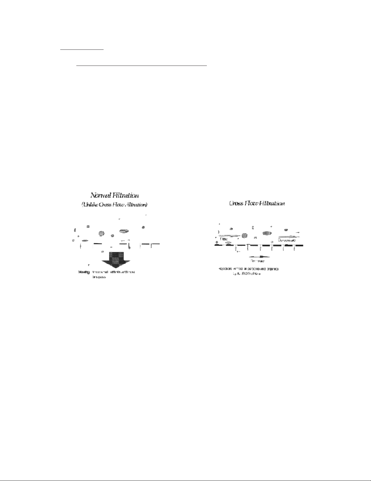
Reverse osmosis is the separation of one component of a solution from another component by
means of pressures exerted on a semipermeable membrane element. Removal of ionic, organic and suspended / dissolved impurities occurs during the RO process. Unlike a filter, which
separates by “normal” filtration, the General Electric (GE) Osmonics membrane element separates using a process called cross flow filtration. Feed water solution is separated into two
streams, permeate and concentrate, and collected from both sides of the membrane element. A
semipermeable RO membrane element, under sufficient pressure, allows passage of purified
water while rejecting and concentrating dissolved and suspended solids.
Figure 1.1
Normal Versus
Cross Flow Filtration
GE Osmonics manufactures a patented spiral-wound membrane element package, with a turbulent flow design. This membrane element collects the purified water within a central tube,
the permeate tube (Figure 1.2, Membrane Element with Interconnectors and Figure 1.3, Cross
Sectional View of Membrane Element).
1
Page 8
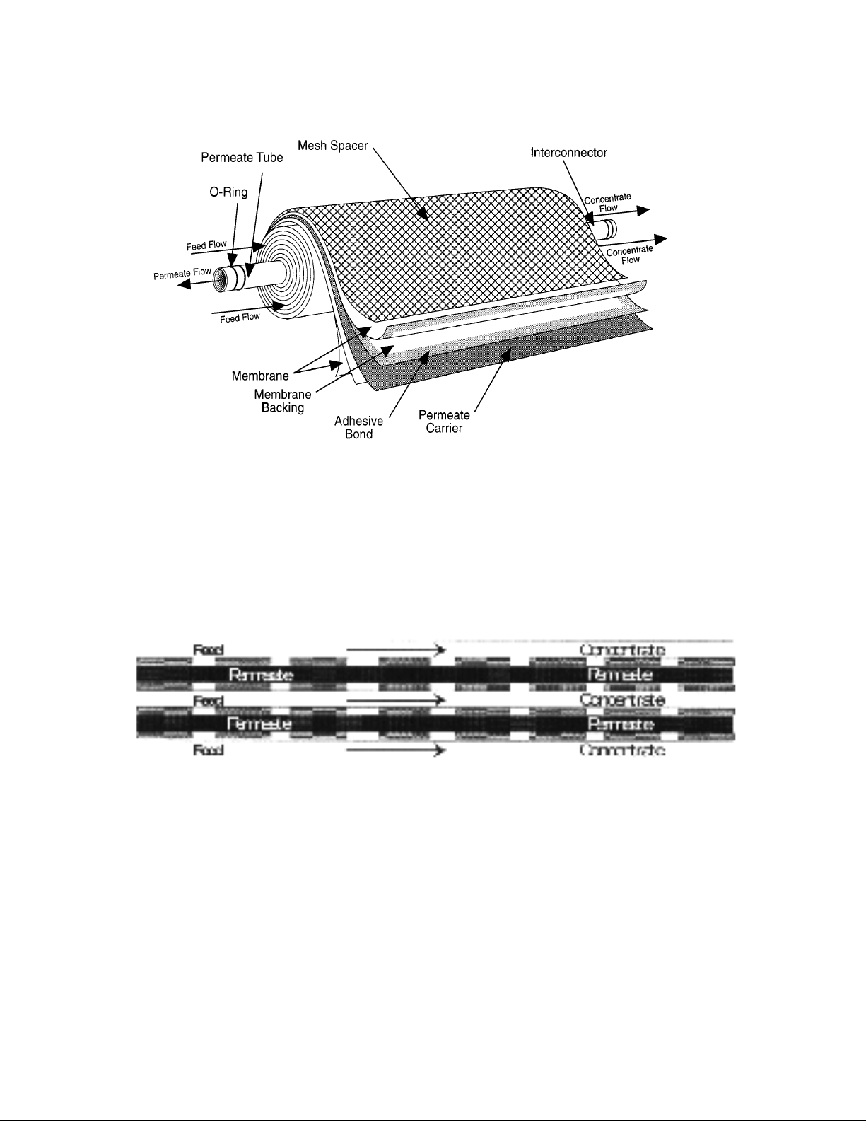
Figure 1.2 - Membrane Element
with Interconnectors
Figure 1.3
Cross Sectional View of
Membrane Element
2
Page 9
Some operating definitions are provided to help you further understand your machine:
Permeate Rate [Product Water Rate (Qp)] is the flow rate of purified water which has
passed through the membrane element and out of the membrane element housing;
expressed in gal/min (gpm) or gal/hr (gph) [in metric, liter/min (Lpm) or cubic
meters/hour (m
3
/h)]. Specified permeate rates are normally at 77ºF (25ºC).
Concentrate Rate [Waste Water Rate (Q
c
)] is the flow rate of water containing reject-
ed solids to drain in gpm or gph (Lpm or m3/h).
Feed Rate (Q
f
) is the flow rate of incoming water in gpm or gph (Lpm or m3/h).
Feedwater rate equals permeate rate plus concentrate rate.
Recovery equals permeate rate divided by feed rate and is expressed as a percentage.
For example, 33% recovery means that out of a given feed rate, 33% is produced as
purified water (permeate).
Concentration equals the Total Dissolved Solids (TDS) concentration of a solution
expressed as milligrams per liter (mg/L) or conductivity (microSiemens/cm).
C
f
= Feed Concentration
C
p
= Permeate Concentration
C
c
= Concentrate Concentration
C
avg
= Average Concentration in Machine
Salt (Ionic) Rejection equals the percent of dissolved salt rejected by the membrane
element, calculated from an average concentration over the membrane.
Salt (Ionic) Passage equals (100% - rejection) or the percent of dissolved salts passed
through the membrane element.
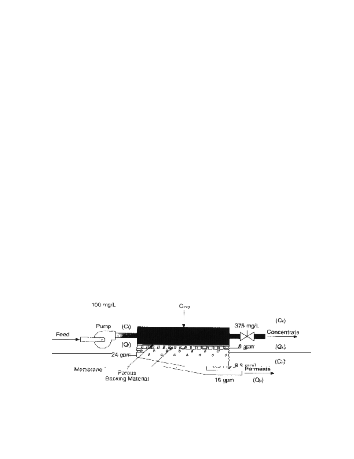
An example of how to calculate salt rejection and recovery is given below:
Figure 1.4
Principles of Operation
3
Page 10

Flow Description - The feed water passes through a replaceable 5-micron cartridge
pre-filter which removes bulk suspended solids. Filtered water then flows to the inlet control valve. This solenoid-controlled diaphragm valve is wired to the ON/OFF switch and
opens when the machine is turned ON, allowing water to flow to the pump inlet. When
the machine is turned off, the valve closes, preventing non-turbulent flow through the
membrane elements, which would lead to shortened membrane element life.
The pump feeds water to the membrane element housings arranged in parallel and serial
combinations. The direction of water flow is indicated by an arrow on each membrane element housing. Water is separated by the membrane elements within the membranes and
leaves the membrane element housings in two streams: permeate and concentrate.
Permeate from each membrane element housing is collected in a common manifold. The
permeate then flows through a flow meter and to the outlet point of the machine.
The concentrate leaves the last membrane element housing and flows to the flow control
center (recycle/concentrate manifold). At this point, the recycle valve channels a predetermined amount of concentrate into the pump inlet. Recycle increases recovery while
maintaining adequate cross flow through the membrane elements. The other two ports of
the flow control center lead to the concentrate valve and final pressure gauge. The concentrate valve has three functions: It controls the amount of concentrate flowing to the
drain; it controls the pressure within the machine; and it helps control the system recovery. An Autoflush solenoid is added to the flow control center with an additional tee. The
concentrate then flows through a flow meter and to the outlet point of the machine.
1.2 Machine Nomenclature
GE Osmonics E-Series water purification machines are numbered in such a way as to indicate the permeate flow and quality you can expect from the machine.
4
Given the system case in Figure 1.4 (Principles of Operation):
Average Concentration (C
avg
) = (Cf) 100 mg/L + (Cc) 146.9 mg/L
2
(C
avg
) = 123.5 mg/L TDS
Rejection = (Cavg) 123.5 - (Cp) 6.2 x 100 = 95%
(C
avg
) 123.5
Passage = (Cp) = 6.2 x 100 = 5.0%
(C
avg
) = 123.5
Recovery = (Qp) 2 gpm x 100 = 33%
(Qf) 6 gpm
Page 11

Example: E4H-21K/ECN, 230, 6, 50-75
• E4H indicates the machine series
• H indicates horizontal membrane element housing configuration
• 21K indicates the rated permeate flow in thousands of gallons per
day @ 77ºF (25ºC),(i.e., 21K = 21,000 gallons per day)
• ECN indicates Economy Model and DLX indicates the Deluxe
Model
• 230 indicates 230 VAC, three-phase voltage to starter
• 6 indicates 60 Hz operation, whereas 5 indicates 50 Hz operation
• 50 - 75 indicates 50% to 75% recovery
1.3 Machine Permeate Quality
The permeate rejection performances are as follows:
E4H machines use high rejection Osmo 415 - HR(PA) membrane elements, providing the
ultimate in high purity water.
1.4 Economy and Deluxe Model Options
1.4.1 Economy Model
E-Series Economy (ECN) model water purification machines have all the features
necessary for safe, continuous production of high purity water. This assumes good
quality feed water, adequate pretreatment and regular operator maintenance, each
shift or daily, to the operation of the system.
• 50% to 75% recovery
• Multi-stage centrifugal pump, SS construction (stainless steel castings with
Noryl stages)
• Base model electrical package includes NEMA-1 enclosure with a
110 VAC, 60 Hz or 220 VAC, 50 Hz single-phase control circuit; applies to
all ECN models
• Automatic inlet shutoff valve
• Pre-filter housing and 5-micron cartridge pre-filter
• Pre-filter, post-filter, primary and final pressure gauges
5
Page 12

• Digital concentrate and permeate flow meters
• Digital conductivity monitor, panel-mounted, for permeate quality monitoring
• Autoflush System - programmable, automated high-velocity membrane element flushing for the longest membrane element life; set at the factory and
adjustable in the field
• Gauges, valves and rigid piping of stainless steel or plastic
• Membrane element housings, all 304 stainless steel (SS), with Noryl end
caps
• 316 SS concentrate and recycle valves
• All components in contact with the purified water (permeate) are either
FDA-acceptable plastic [nylon, Noryl, polypropylene, polyvinyl chloride
(PVC)] or stainless steel materials.
• All high pressure fittings are 304 SS.
• Alarms included: low inlet pressure and high amp draw.
1.4.2 Deluxe Model Options
The Deluxe (DLX) package contains all of the above Economy (ECN) standard
features along with a PROGRAMMABLE LOGIC CONTROLLER (PLC) control system.
• Multi-stage centrifugal pump, stainless steel construction (316 stainless
steel end castings and other wetted parts, Noryl internals)
• Autoflush System - programmable, automated high-velocity membrane ele-
ment flushing for the longest membrane life; set at the factory and
adjustable in the field
• All high-pressure fittings are 304 stainless steel.
• Special electrical upgrade package includes PROGRAMMABLE LOGIC
CONTROLLER (PLC) controller with alarm delay shutdown for low inlet
pressure condition to prevent pump damage should pressure fall below
15 psig (1 barg)
• Clean-In-Place (CIP) system
• Digital flow meter and conductivity controller
• Digital pH controller
6
Page 13

• Alarms included: low inlet pressure, high amp draw, high / low pH
1.5 Specifications for E-Series Machines
1.5.1 Feed Water Requirements
Table 1.1
Feed Water Requirements
1.5.2 Permeate (Product Water) Flow Rate
Stated on the serial number label (assumes no permeate back pressure,
2000 mg/L TDS maximum feed concentration, and rated temperature).
To estimate permeate output with back pressure, use the formula below:
Permeate Back Pressure: Maximum: 80 psig (5.5 barg)
Permeate Outlet: 1-inch FNPT
7
Temperature
Inlet Pressure
Chlorine
(continuous feed)
Operating pH
Pre-filter
Inlet Connections
35° - 77°F (2° - 25°C) Not to exceed
85°F (29°C) unless specifically
designed for higher temperatures
Minimum: 30 psig (2.1 barg)
Maximum: 60 psig (4.1 barg)
For Osmo HR(PA) membrane elements: 0 ppm
Soft water [less than 1 grain per gallon: 3.0 - 10.0 (gpg) or 17 mg/L hardness], acceptable pH: 5.5 - 6.0
5 micron HYTREX cartridge
(part number on machine label)
1.5-inch FNPT*
(Permeate Flow on Label) x [(Operating Pressure) - (Permeate Back Pressure)]
Operating Pressure
* FNPT: Female National Pipe Thread
Page 14

8
1.5.3 Concentrate Flow Rate
Factory set as stated on serial number label
Concentrate Outlet: 1-inch FNPT
1.5.4 Typical Pure Water
Recovery: 50 - 75%
1.5.5 Final Operating Pressure
Minimum: 200 psig (13.8 barg)
Maximum: 235 psig (16.2 barg)
1.5.6 Pump
Multi-stage centrifugal, approximate primary operating pressure of 190 psig
(13.1 barg), excluding line pressure.
1.5.7 Reverse Osmosis Membrane Element Rejection
Osmo HR(PA)
Typical Ionic Rejection (TDS) 95 - 98%
Average Molecular Weight Cutoff* 150 MW*
* The Molecular Weight cutoff is based on the pore size of the membrane elements and the nature
(size/shape) of the organic molecule.
Page 15

9
SALTS
CATIONS
Percent Maximum
Percent Passage Concentration
Name Symbol Rejection (Avg) Percent
Sodium Na
+
94-96 5 5-10
Calcium C a
+2
96-98 3 *
Magnesium M g
+2
96-98 3 *
Po tassium K
+1
94-96 5 5-10
Iron F e
+2
98-99 2 *
Manganese M n
+2
98-99 2 *
Aluminum Al
+3
99+ 1 10-20
Ammonium N H
4
+1
88-95 8 3- 8
Copper Cu
+2
98-99 1 10-20
Nickel Ni
+2
98-99 1 10-20
Zinc Zn
+2
98-99 1 10-20
S trontium Sr
+2
96-99 3 Hardness Ca & Mg 96-98 3 *
Cadmium Cd
+2
96-98 3 10-20
Silver A g
+1
94-96 5 *
Mercury H g
+2
96-98 3 -
ANIONS
Chloride Cl
-1
94-95 4 5- 8
Bicarbonate H C O
3
-1
95-96 4 5-10
Sulfate S O
4
-2
99+ 1 5-15
Nitrate N O
3
-1
85-95 10 3- 6
Fluoride F
-1
94-96 5 5- 8
Silicate Si O
2
-2
80-95 10 Phosphate P O
4
-3
99+ 1 10-20
Bromide Br
-1
94-96 5 5- 8
Borate B4O
7
-2
35-70** - Chromate CrO
4
-2
90-98 6 8-12
Cyanide C N
-1
90-95** - 4-12
Sulfite S O
3
-2
98-99 1 5-15
Thiosulfate S
2O3
-2
99+ 1 10-20
ORGANICS
Maximum
Molecular Percent Concentration
W eight Rejection Percent
Sucrose Sugar 342 99.9 30-35
Lactose Sugar 360 99.9 30-35
Protein 10,000 Up 99.9 50-80
Glucose 180 99.0 15-20
Phenol 94 ***Acetic Acid 60 * **Formaldehyde 30 ***Dyes 400 to 900 99.9 Biochemical
Oxygen Demand (BOD) 90.0-99.9
Chemical Oxygen Demand (COD) 99.9
Urea 60 40-60 Reacts si m ilar to
a salt
Bacteria & Virus 50,000 to 99.9+
500,000 -
Pyrogen 1,000 99.9+ -
to 5,000
*** Permeate is enriched in material due to preferential pas -
sage through the membrane.
GASES, DISSOLVED
Carbon Dioxide C O
2
30-50%
Oxygen O
2
Enriched in permeate
Chlorine Cl
2
30-70%
To estimate p assage of salts for membrane elements other than SEPAHR, take the p assage for the SEPA-HR and multiply by the factor for the
passage for the particular membrane element. The factors are:
S E PA-SR is 1.6 times SEPA-HR passage
S E PA-PR is 2.5 times SEPA-HR passage
Operation of the SEPA-HR membrane element at pressures over 400 ps ig
(27.6 barg) will reduce salt passage slightly . Operation at 200 p sig (13.8
bar) will increase the p assage of monovalent ions by approximately 2.0
times and the passage of multivalent ions will increase by 1.5 times the
400 psig (27.6 bar) p assage.
For SEPA membrane elements with larger pores than the SEPA-PR it is
recommended that actual tests be run prior to estimating the permeate
quality.
The maximum concentrations given in the table are the approximate
concentrations resulting in an osmotic pressure of 500 psi (34.5 barg)
for the solution.
Compounds such as CaSO
4
which have specific solubility limit s can be
controlled with proper addition of dispersants. Check with the factory for
more information on Osmonics special line of dispersants .
* Must watch for precipit ation; other ion controls maximum
concentration
** Extremely dependent on pH; tends to be an exception to the
rule
The following are typical rejections and passages for various salt s and
organics using the SEPA
fi
-HR membrane at 400 psig (27.6 bar) operat -
ing pressure. Modules made with this membrane, such as the OSMO
fi
HR, can be expected to give these same passages. As can be seen,
multivalent ions tend to have less passage than do monovalent ions. If
monovalent ions are combined with multivalent ions to form a salt, the
passage will be controlled by the multivalent ion. In RO all ions must be
combined as the salt form before passages can be considered.
For estimating purposes, to obtain the expected permeate quality when
handling a solution of salts , take a simple average of the feed concentra tion and the
concentrate concentration and multiply this figure by the average percent passage to calculate the average concentration of the
permeate.Salts or organics that are complexed with organics of large
molecular weights will tend to act like the organics with which they are
complexed.
NOTE: The actual permeate water quality will vary with the inlet water quality and can only be veri-
fied by actual analysis of the permeate stream.
Figure 1.2
Typical Membrane Element
Rejections/Passages
Page 16

10
2.0 INST
ALLATION
2.1 Mounting
E4H machines are equipped with a stand alone frame, 61-inch (155-cm) H x 132-inch (335
cm) W x 34-inch (86 cm) D, which supports the machine. At least 45 inches
(114 cm) of space should be allowed on each end of the membrane element housings for
removal and loading of membrane elements. If 45-inches (114 cm) are not available, the
entire membrane element housing may need to be removed for membrane element
changes.
2.2 Piping
2.2.1 Inlet Piping
The feed water source is piped to the inlet using 1.5-inch NPT fittings. A CIP
system is supplied with the DLX Model E4H. FOR ECN MODEL: To install a
CIP system, remove plug and install valves on the E-Series machine as described
in Section 2.2.2. If the inlet pressure is in excess of 60 psig (4.1bar) or fluctuates
by more than 5 psig (0.4 bar), a pressure regulator should be installed ahead of the
CIP tee.
2.2.2 Required Valves for Clean-In-Place
NOTE
: Clean-In-Place (CIP) valves are only required for Economy (ECN)
Models.
IMPOR
TANT NOTE: GE Osmonics has installed a plugged pipe tee in the
inlet line of the E4H units. This plug, when removed,
will facilitate cleaning of the unit. A tee with (two)
two-way valves or a single three-way valve should also
be installed on the permeate and concentrate outlets to
allow flow back to the cleaning tank. Never operate
the machine with the concentrate or permeate lines
blocked. Severe damage to the unit may result. (Refer
to the attached drawing # 1163858 for a system flow
schematic.)
2.2.3 Concentrate Outlet Connection
Install the CIP valve on the concentrate outlet tee, connect a 1-inch hose or pipe,
and run it to an open drain. To avoid drainage from the machine while not in use,
the concentrate outlet piping should be placed at a height at least equal to the
height of the machine. Asiphon break may also be installed in the concentrate line
for added protection. The concentrate outlet hose can be any length, and the diameter should match the outlet on the machine. [Maximum back pressure is 60 psig
(4.1 barg).]
Page 17

2.2.4 Permeate Outlet Connection
Install the CIP valve on the permeate outlet tee. The pure water (permeate) should
be transported to the point of use via non-corroding-type tubing, pipe, or hose.
Examples are: food-grade flexible nylon tubing, stainless steel tubing, or PVC
hose. The permeate outlet is 1-inch FNPT.
2.3 Electrical
The DLX and ECN E-Series models are supplied with a single-phase, 110 VAC 60 Hz or
220 VAC 50 Hz control circuit and 8-foot cord which plugs into a three-prong
grounded receptacle. For 220 VAC, 50 Hz units, plug must be customer-supplied. A
20 amp dedicated service circuit is required for proper operation.
For each model, the motor is wired at the factory to an overload protection magnetic motor
starter which is controlled by a panel-mounted manual switch.
The electrical system control circuit is separate from the motor voltage. Therefore,
electrical wiring required in the field needs two supply voltages, the control circuit
voltage and a separate three-phase motor voltage. All field wiring must comply with
applicable local and national electric codes.
2.3.1 Economy Electrical System
STEPS
1. Connect the control circuit power cord to 115 VAC, 60 Hz, or 220 VAC,
50 Hz, single-phase power.
2. Connect the magnetic motor starter 230/460 VAC or 220/380 VAC,
three-phase power to match the motor voltage and phase. Check the tag
(located on the motor starter) that indicates the factory wiring. Aseparate,
fused disconnect for the motor wiring is required, with proper protection
for the Hp and amp draw of the motor.
Refer to drawing #1164309 for the ECN electrical diagram. The ECN
circuit has a timing relay for delayed machine shutdown.
2.3.2 Deluxe Electrical System
STEPS
1. Connect the control circuit power cord to 115 VAC, 60 Hz, or 230 VAC,
50 Hz, single-phase power.
2. Connect the magnetic motor starter 230/460 VAC or 220/380 VAC,
three-phase power to match the motor voltage and phase. Check the tag
(located on the motor starter) that indicates the factory wiring. Aseparate,
fused disconnect for the motor wiring is required, with proper protection
for the Hp and amp draw of the motor.
11
Page 18

3.0 PREPARATION AND START-UP
3.1 Pretreatment for Water Purification
All systems will operate most efficiently on filtered water with a pH of less than 6.5 and a
Silt Density Index (SDI) of 5 or below. If the machine is operated on higher pH water,
other forms of pretreatment may be necessary. A water analysis prior to start-up of the
machine is required. To minimize the chances of calcium carbonate, calcium sulfate, or
other salt precipitation on the membrane, GE Osmonics evaluates each application and
water condition and makes specific recommendations to ensure continuity of the membrane membrane element warranty. Data from the water analysis is processed with a computer program analysis to determine if potential problems exist. If the machine is to be run
at a different location than was originally intended, a new water analysis is required for
warranty consideration and should be sent to GE Osmonics for review and recommendations for operation of the machine.
Before entering the machine, the feed water must be filtered to 5 microns.
Thin-layer composite (TLC) membrane element feed water must not contain the following
chemicals or permanent loss of rejection and/or permeate flow may
result:
• free chlorine
• formalin (until after a membrane elements have been run for 24 hours; thereafter,
0.5% formaldehyde may be used as a biocide)
• iodine compounds
• quaternary germicides
• cationic surfactants
• detergents containing non-ionic surfactants
• cleaners not approved by GE Osmonics
CAUTION
: A water softener should not regenerate while the machine is running
unless safeguards are used to be sure the machine is operated on softened
water during regeneration.
3.2 S
tart-Up
NOTE: If your machine is provided with the membrane elements installed in the hous-
ings, proceed to 3.2.1. If your machine is provided with the membrane elements
in shipping boxes, you must load the membrane elements in the housings prior
to starting the machine. For membrane element loading instructions, skip to
Section 4.6 (Membrane Element Installation). Upon completion of membrane
element installation, return to Step 1 to continue your start-up procedure.
12
Page 19

STEPS
1. Re-check the function and integrity of your pretreatment equipment.
Ensure that your water softener, activated carbon filters and iron filters
(where applicable) have been leak-checked, backwashed, and thoroughly
rinsed for service before starting up your RO unit.
2. Attach the feed water pipe to the inlet of the machine.
3. Check for leaks at all connection points.
4. Turn ON the feed water gradually and check for leaks in the inlet piping.
No flow should go through the machine while the power is OFF and the
inlet solenoid is in the closed position.
NOTE
: When the machine is OFF, there should never be flow through
the machine. Flow through the machine when it is OFF can ruin
the membrane elements, and the inlet solenoid must be repaired.
5. Attach tubing from permeate and concentrate outlet points and run the
tubing to drain.
6. Ensure that you have made provisions for both voltages required to operate your machine. The machine requires two power sources: (1) the high
voltage for the motor operation, and (2) the control circuit power supply.
The factory provides the 110 VAC (or 220 VAC 50 Hz) power cord needed for the control circuit. The motor electrical service must be field-wired
directly into the motor starter on the machine. Bring your motor service to
terminals labeled “T” on the motor starter. Check the voltage label to
ensure that you have brought the correct voltage to the starter.
7. Be sure the power to the motor starter is de-energized.
8. With the machine ON/OFF switch in the OFF position, plug in the factory supplied 110 VAC (or 220 VAC 50 Hz) power cord.
9. Open your concentrate and recycle flow control valves two complete
turns. These valves are positioned on the flow control center of the
machine. This piping is located on the left section of the machine, near
the membrane element housings. The flow control center features a concentrate flow control valve, a recycle flow control valve, and a pressure
gauge sensor point piped into the panel-mounted pressure gauge.
NOTE
: The Autoflush valve is positioned in this flow control center.
The proper adjustment of these valves is critical to the operation of the RO
machine. The concentrate valve determines the amount of rejected water
leaving the machine, and creates the operating pressure shown on the
pressure gauge. The recycle valve returns unused reject flow back into the
13
Page 20

inlet stream to the RO pump. It is important to balance the operating pressure and the respective flows of these valves to ensure that your machine
is operating correctly. It is also important to understand the relationship of
these two valves, the pressure gauge, and your RO pump. The pump has
a fixed amount of flow produced, and the valves are the control devices to
distribute this fixed flow amount. The pressure gauge is an indicator of
applied membrane element pressure, at the flows set by the valves.
10. Turn the ON/OFF switch to the ON position. Water will begin to flow
through the machine at this point but the pump will not start. Allow the
machine to operate in this manner for 10 minutes, to purge the air out of
the machine. Verify alarm set points in the Lakewood 2450 Reverse
Osmosis controller.
Consult the Lakewood Model 2450 Installation and Operation Manual
(P/N 1109695) for operating instructions. The factory alarm set points are
as follows:
Low Inlet Pressure 12 psig (0.83 barg)
Low pH 2.0
High pH 8.0
pH Control 5.6 - 6.2
High Temperature 120°F (49°C)
NOTE
: The high-pressure pump should not be operating at this time.
11. As your machine is filling check for leaks and repair as needed.
12. Turn the ON/OFF switch to the OFF position.
13. Energize the power source to the motor starter. The pump should not operate at this point.
14. Check the rotation of the high-pressure pump by briefly turning the
ON/OFF switch to the ON position. Watch the motor, or coupling shaft,
for direction of rotation. The motor should rotate clockwise as one looks
at the motor end of the high-pressure pump. If the motor is not rotating
clockwise, change any two of the three leads (for three-phase) in the
motor starter and recheck rotation. Always turn the power off to change
any wiring.
W
ARNING
: OPERATION OF THE PUMP BACKWARDS, EVEN
FOR A SHORT TIME, CAN CAUSE DAMAGE TO
THE PUMP.
15. Turn the ON/OFF switch to the ON position. The high-pressure pump will
operate and the machine will begin to build pressure. As you are operating, be sure to watch the pressure gauge on the instrument panel. The
machine is designed to operate at 220 psi (15.2 bar).
14
Page 21

NOTE: Do not allow the pressure to exceed 250 psi (17.2 bar). If the
pressure exceeds 250 psi (17.2 bar), open the concentrate flow
control valve until the pressure gauge shows 250 psi (17.2 bar)
or less.
As the machine purges the air and fills with water, the pressure will gradually increase. You should see water flowing through the permeate and
concentrate flow meters. If you do not see flow, turn the machine OFF and
return to Step 1.
W
ARNING:
NEVER ALLOW THE MACHINE TO OPERATE
WITHOUT ADEQUATE WATER PRESSURE. THIS
CAN CAUSE SEVERE DAMAGE TO THE HIGHPRESSURE PUMP
.
16. Gradually close the concentrate flow control valve. As you close the
valve, watch the pressure gauge and your concentrate flow meter. Close
the valve until your concentrate flow meter displays your design flow, and
you do not exceed 250 psi (17.2 bar). If you reach 250 psi (17.2 bar)
before the valve is completely closed, open the recycle flow control valve
one full turn, then continue to close the concentrate flow control valve.
Continue to close the concentrate flow control valve until it is completely closed and your pressure is below 250 psi (17.2 bar).
The concentrate flow control valve has a drilled orifice to ensure a predetermined amount of flow and pressure in the closed position. This orifice
is sized to operate the machine at 75% recovery.
17. With the concentrate flow control valve fully closed and the pressure
below 250 psi (17.2 bar), gradually close the recycle flow control valve
until the pressure reaches 250 psi (17.2 bar).
Your machine is now operating at the design pressure and flow rates, in a
75% recovery configuration. Your specific needs or conditions may dictate the need to operate the machine at a lower recovery. If you wish to
operate in a recovery configuration lower than 75%, Step 18 (below) will
explain the necessary steps.
18. Your machine is equipped with flow meters and a pressure gauge that will
assist you in setting alternate flow rates for variable recoveries. If you
wish to operate at a recovery lower than 75% you must ensure that the
flow rates for the permeate and concentrate are at desired levels. Some
minor adjustments in the concentrate and recycle flow control valves may
be necessary.
See Table 3.1 (Machine Recovery) below for specified flow rates for various machine recoveries. When you have selected your desired flow rate,
gradually adjust the concentrate flow control valve to achieve desired
flow and use the recycle valve to bring the operating pressure up to
250 psi (17.2 bar).
15
Page 22

Once the desired flow rate is achieved [250 psi (17.2 bar) operating pressure] no further valve adjustment is needed.
The table below shows flow rates at 50%, 66% and 75% recovery for the
E4H models. Use this table in adjusting flow rates.
NOTE
: Permeate flow rates are dependent upon temperature and con-
ditions at your site. Contact your dealer if you have any questions.
Table 3.3
Machine Recovery
19. The system is now operational.
20. Before putting the machine into final operation, continue to run the per-
meate and concentrate streams to drain for at least 30 minutes. This is
done to ensure that all of the bactericide has been removed from the membrane elements.
21. Connect the permeate line to the point of use of the permeate. Check for
leaks and ensure that you have no kinks in hoses, or blockage of any piping on the permeate and concentrate outlet lines.
22. Make any necessary final adjustments to flows and pressure according to
Step 18.
NOTE
: The membrane elements in your machine are rated for certain
flow rates at 77ºF (25ºC). Maximum flow rates are achieved
when the membrane elements have been completely rinsed and
on-line for at least 24 hours.
16
at 50%, 60%, and 75%
Recovery
11.2 (2.6)
15.0 (3.4)
18.8 (4.3)
26.2 (6.0)
30.0 (6.8)
at 50%
Recovery
11.25 (2.6)
15.00 (3.4)
18.75 (4.3)
26.25 (6.0)
30.00 (6.8)
at 66%
Recovery
5.80 (1.3)
7.73 (1.8)
9.66 (2.2)
13.52 (3.1)
15.45 (3.5)
at 75%
Recovery
3.75 (0.9)
5.00 (1.1)
6.25 (1.4)
8.75 (2.0)
10.00 (2.3)
E4H-16K
E4H-21K
E4H-27K
E4H-38K
E4H-43K
Permeate Flow
[gpm (m3/h)]
Concentrate Flow
[gpm (m3/h)]
Page 23

23. A Daily Log Sheet (Section 10.0) which includes general operating con-
ditions (pressures, flows, concentrations, pH, and pretreatment conditions), and routine or special maintenance (flushing or cleaning as needed) must be kept. This Daily Log Sheet will be required by GE Osmonics
if a warranty question arises.
17
Page 24

18
4.0 OPERA
TION AND MAINTENANCE
The operation and maintenance of your GE Osmonics E4H Machine is relatively simple but
requires regular data recording and routine preventative maintenance. We cannot emphasize too
strongly the importance of filling out the daily log sheet during each operating shift. A data sheet
was filled out upon start-up containing pertinent facts on the operation of your machine. These
two records are invaluable in diagnosing the performance of the equipment and must be kept for
reference. If you have questions concerning the operation of your machine or the method of data
recording, contact the GE Osmonics Application Engineering Department.
The three preventative maintenance procedures which must be done on a regular basis are as fol-
lows:
1. Change the pre-filter cartridge.
2. Flush the machine daily.
3. Clean the machine with approved GE Osmonics cleaners.
See the following sections for specific maintenance procedures.
4.1 Daily Log Sheets
A Daily Log Sheet (Section 10.0) which includes general operating conditions (pressures,
flows and concentrations) and routine or special maintenance (pre-filter changes, flushing,
cleaning, etc.) must be kept. Copies of the log can be made from the template. A copy of
this log sheet will be required by GE Osmonics if a warranty question arises.
4.2 Pre-Filter Cartridge
A 5-micron pre-filter is factory-installed to protect the membrane elements and valves
from particles which may be in the feed water. The pre-filter uses two 20-inch (50.8-cm)
diameter, 5-micron nominal rated cartridges. To order replacements, contact your
distributor.
The pre-filter cartridges must be replaced, at a minimum, once per week or after every 100
hours of operation, whichever comes first. A pressure drop of 8 psig (0.6 bar) across the
filter or more during operation indicates one or more cartridges need changing. Use only
Osmonics approved filters rated for 5 microns or less. Do not attempt to clean used
filters - install new replacements.
IMPOR
TANT NOTE: Failure to change the pre-filter according to these requirements
will void the warranty.
Page 25

4.3 Flushing
The machine should be flushed at least daily to remove sediment from membrane element
surfaces. To flush the unit:
STEPS
1. Open the concentrate valve until the pressure gauge indicates the minimum pressure designated on the nameplate. This increases the flushing action on the membrane element.
NOTE: If pressure will not decrease to designated pressure, or if the concentrate
rate does not increase when the valve is opened, the valve may be
plugged.
2. Operate the machine at the designated minimum pressure for 10 to 20 minutes.
CAUTION
: Do not operate the machine below the designated pressure
without approval from GE Osmonics. Operation below the
stated pressure may be detrimental to the pump.
3. Close the concentrate valve and ensure that the proper concentrate flow rate is
going to the drain (see the nameplate on the panel).
NOTE
: The Autoflush (AUF) system, available in DLX packages, automati-
cally flushes the machine and eliminates the need for frequent manual
flushing.
4.4 Cleaning
Cleaning the E4H-Series machine on a regular basis is vital. Over time, contaminants
build up to form a layer on membrane element surfaces, reducing the permeate flow and
quality. If this build-up is not removed from the membrane element, it may cause permanent chemical damage and reduce membrane element life. A decrease in permeate flow
and/or rejection of salts, or an increased pressure drop across the machine will indicate
when cleaning is required. Cleaning may be required as often as once every week or as
infrequently as every two months, depending upon the local water supply conditions.
GE Osmonics recommends cleaning at least every month to ensure good membrane element performance and long membrane element life.
GE Osmonics offers a full line of chemical cleaners for specific cleaning needs. See
Table 4.4 (Dry Chemical Cleaners).
19
Page 26

Table 4.4
Dry Chemical Cleaners
CLEANING PROCEDURE
STEPS
1. With the RO machine running, open the Clean-In-Place (CIP) permeate valve. After this
valve has been opened, close the permeate service valve. Permeate water will flow into
the CIP tank. Allow the water to run through the CIP tank and the CIP tank drain valve
for a few minutes to ensure the tank is rinsed thoroughly. After a minute or so, close the
CIP tank drain valve. The CIP tank should begin to fill with RO permeate. When the CIP
tank has filled to the indicated full line, turn the ON/OFF switch on the RO machine to the
OFF position.
2. While the machine is OFF, open the CIP inlet valve. Divert the permeate and concentrate
streams to the cleaning container for recirculation. Ensure that the pre-filter is clean. A
CIP pump (supplied with DLX models only) is recommended to supply feed pressure into
the machine.
3. To circulate the cleaning solution through the machine with suction, remove the CIP plug.
Use a non-collapsible suction hose or pipe to feed the machine.
NOTE
: Do not allow the machine pump to operate without concentrate flow. If pump
prime is lost while cleaning on suction, positive inlet pressure is required to
reprime. No air should be sucked into the inlet line during suction cleaning.
20
Description
Dry acid-surfactant for cleaning TLC, PA
and CA membrane elements.
High pH alkaline cleaner for PA membrane
elements. Recommended for situations
where microbial fouling is a problem. DO
NOT use on CA membrane elements.
Cleaner intended to deal with sulfate
or iron precipitation fouling. Recommended
for CA and PA membrane elements.
Cleaner
Osmo AD-20
Osmo AK-110
Osmo ET-70
Part Number
1155420
1155421
1155422
1155423
1155416
1155417
1155418
1155419
1155424
1155425
1155426
1155427
Quantity
8 x 4 lb. pkgs/case
45 lb. pail
100 lb. key
300 lb. drum
8 x 4 lb. pkgs/case
45 lb. pail
100 lb. key
300 lb. drum
8 x 4 lb. pkgs/case
45 lb. pail
100 lb. key
300 lb. drum
Page 27

4. Turn the CIP ON/OFF switch to the ON position and recirculate the cleaning solution through the machine. The cleaning solution should be recycled for approximately 15 minutes or until the solution temperature reaches 85°F (29°C). If heat
rise occurs too quickly, larger volumes of cleaning solution or the use of a heat
exchanger will slow the temperature rise. Turn the CIP OFF and allow it to soak
for 10 minutes.
TLC MEMBRANE NOTE
: It is best to clean at temperatures of
100°F - 110°F (38°C to 43°C), but lower temperatures will suffice. Do not allow the cleaning
temperature to exceed 110°F (43°C). Allow the
cleaning solution to recirculate for 10 minutes.
Turn the machine off and allow the membrane
elements to soak in the solution for approximately 20 minutes.
W
ARNING
: DO NOT LEAVE THE CLEANING STRENGTH SOLU-
TION IN THE MACHINE FOR A PERIOD LONGER THAN
ONE HOUR. THE CLEANING SOLUTION MAY DAMAGE THE MEMBRANE ELEMENTS AND/OR THE
MACHINE DURING AN EXTENDED PERIOD OF CONTACT.
5. To flush the detergent from the machine, close the CIP inlet valve and divert the
permeate and concentrate to drain by opening the CIP drain valve. Operate the
machine as described in the flushing section (Section 4.3, Flushing) for at least one
hour. The detergent is sufficiently flushed when the permeate conductivity is
restored to nearly its previous level.
6. To return the RO to service, open the permeate, concentrate valves so that flow is
routed as intended in the service mode. Close the CIP permeate, CIP concentrate
valves. The RO is now ready for operation.
4.5 Draining Machine for Shipment
Prior to shipping or outside storage of a GE Osmonics E4H Machine, the system should
be cleaned with the appropriate cleaner, flushed with water, and protected from biological
attack with the appropriate solution for TLC membrane. The membrane element housings
and piping lines of the machine must be completely drained. Any water remaining in the
piping of a machine may freeze, causing damage to the piping, pump, membrane elements,
etc. The party shipping or storing the machine is responsible for any damage resulting
from freezing.
STEPS
1. Disconnect the inlet, concentrate and permeate outlets.
2. Drain all water from the cartridge filter housing.
21
Page 28

3. Remove the tubing connections on the inlets and outlets of the membrane element
housings.
4. Open the concentrate valve.
5. Remove the drain plugs from all PVC manifolds.
6. Be sure the flow meters are drained by disconnecting the bottom fitting of each
flow meter.
7. Allow the machine to drain for a minimum of eight hours or until the opened ports
quit dripping.
8. After draining is complete, reconnect all of the piping.
4.6 Membrane Element Installation
NOTE: For machines with membrane elements not loaded at the factory, the fol-
lowing steps are to be used for installation.
CAUTION
: The membrane element is packaged in a small amount of bactericide solu-
tion to prevent biological growth; provide adequate ventilation when handling. The membrane element must be kept moist at all times in order to
prevent possible damage to the membrane element material.
STEPS
1. Remove the membrane element bag containing the membrane element from the
shipping tube.
2. Cut the bag open as close as possible to the seal at the end of the bag, so that the
bag may be re-used if necessary.
3. Remove the membrane element from the bag and remove the foam protectors from
each end of the membrane element.
4. Remove the parts from the parts container (if included) and inspect. Make sure that
all parts are clean and free from dirt. Examine the O-rings, brine seal, and permeate tube for nicks or cuts. Replace the O-rings or brine seal if damaged. Set the
membrane element aside in a clean space and continue on to Step 5.
5. Remove the end caps from both ends of all membrane element housings on your
machine. This is done by loosening the clamp bolts at each end cap closure
assembly.
6. Determine the direction of fluid flow in the membrane element housing. (Be certain to look at the “Direction of Flow” arrow for each membrane element housing.
Direction of flow may vary within a given machine.)
22
Page 29

7. Inspect the membrane element housing and clean as necessary to remove any contaminants, obstructions, etc.
8. Apply a small amount of O-ring lubricant to all O-rings on the end caps, and the
brine seal on the membrane element.
9. Insert the downstream end of the membrane element in the upstream end of the
membrane element housing (i.e., load in the direction of flow; the brine seal is on
the end of the membrane element that goes in last. For membrane element housings with the flow arrow pointing up refer to Step 10.
10. Insert the membrane element in the membrane element housing with a smooth and
constant motion. When you reach the point where the brine seal is about to enter
the housing, gently turn the membrane element to ensure the brine seal enters the
housing without coming out of the brine seal groove.
11. When all of your membrane elements are installed, you must close the membrane
element housing by reinstalling the end caps and clamps. It is preferred to install
the bottom end cap first, and tighten the clamp completely, before installing the
top end cap.
12. Reinstall the end caps by gently twisting the end cap while pushing it on to the
permeate tube. Ensure that you do not pinch or fatigue any O-rings while pushing
the end cap on. Push the end cap on until the outer diameter of the cap is flush with
the outer diameter of the membrane element housing. Install the clamp halves, and
tighten the bolts until the clamp halves meet.
13. Reconnect any fittings that were removed when disassembling the membrane element housings.
14. Return to Section 3.2 (Start-Up, Step 1).
4.7 Membrane Element Replacement
As time progresses, the efficiency of the membrane element will be reduced. In general,
the salt rejection does not change much until two-three years after installation, when operated on properly pretreated feed water and when routine maintenance is performed. The
permeate flow rate will begin to decline slightly after one year of operation but can be
extended with diligent flushing and cleaning of the machine. High pH feed water and/or
precipitation of hardness can cause premature loss in rejection and even flow rate. The following procedure is to be followed to replace existing membrane elements in the machine.
STEPS
1. Remove the end caps and clamps from all of the membrane element housings.
23
Page 30

2. Remove all the membrane elements from the membrane element housings in the
direction of flow, where possible. If necessary, a membrane element can be
removed against the direction of flow. A heavy duty pliers or channel lock pliers
may be necessary to pull the old membrane element our of the membrane element
housing.
3. To reinstall replacement membrane elements, follow Steps 4 -14 (Section 4.6,
Membrane Element Installation).
NOTE
: Do not operate the machine on water over 85°F (29°C).
NOTE
: Do not allow the machine to freeze unless it is totally drained. The
machine must thaw a minimum of 24 hours before starting.
24
Page 31

5.0 OPTIONAL ACCESSORIES
5.1 Level Controls
Float switches, pressurized storage switches or other level controls should be wired into
the control circuit line prior to the switch on the unit. The following ensures that the inlet
valve, instruments, and pump are not powered when storage tanks are full: float switch
assembly with cord, counterweight, and plastic float (used with an atmospheric storage
tank).
5.2 Filters and
Water Softeners
Backwashable filters and softeners should be installed such that unfiltered or unsoftened
water will not be fed to the machine while the RO unit is operating. Failure to do this may
cause fouling or precipitation of calcium carbonate or other materials onto the membrane
elements.
5.3 S
torage Tanks
Fiberglass, polyethylene, and stainless steel storage tanks are available. All tanks are
available with fittings installed at the factory. These tanks must be installed with even support along the bottom.
25
Page 32

6.0 TROUBLESHOOTING
26
SYMPTOM
Low operating pressure
Low permeate flow rate
POSSIBLE CAUSES
Insufficient feed water pressure
or flow
Clogged pre-filter cartridge
High flow rates
Dirty or fouled membrane
elements
Solenoid valve not opening
Pump rotating backwards
(three-phase power only)
Insufficient electrical power
Pump not operating correctly
Low operating pressure
REMEDIES
Open the feed pressure, open the
feed water valve, check for
restrictions.
Replace the pre-filter cartridge.
Close the concentrate valve,
check the permeate and concentrate flow rates and adjust if necessary. Excessive permeate flow
may indicate a damaged O-ring.
Flush and clean the membrane
elements.
Clean or replace the solenoid
valve.
Switch any two of the three-
phase leads to the motor starter.
Check the fuses or circuit break-
er, measure the voltage.
See the pump instructions.
See the possible causes for low
pressure.
TROUBLESHOOTING GUIDE
Page 33

27
SYMPTOM
Low permeate flow rate
(continued)
Low concentrate flow rate,
normal or higher than
normal pressure
Pressure does not drop when
concentrate valve opened
POSSIBLE CAUSES
Dirty or fouled membrane
elements
Operating on cold water less
than 55ºF (13ºC)
Membrane elements installed
backwards or damaged
concentrate seal
Flow meter inaccurate
Concentrate valve plugged
Concentrate outlet line restricted
Flow meter inaccurate
Dirty concentrate valve
REMEDIES
Flush and clean the membrane
elements.
Install a hot/cold feed water
tempering valve if more perme-
ate flow is needed. Operate
with a feed water temperature of
72º - 77ºF (22º - 25ºC).
Install membrane elements in
the direction of fluid flow.
Flush and clean the machine
immediately
. Membrane elements with damaged concentrate
seals should be cleaned and may
be returned for repair.
Check the flow rate manually
with a stopwatch and calibrated
container.
Remove the concentrate valve
stem and/or disassemble the
plumbing. Clean the valve.
Examine the concentrate line for
obstructions or kinks, repair or
replace the tubing.
Check the flow rate manually
with a calibrated container.
Disassemble and clean the
plumbing to the valve.
TROUBLESHOOTING GUIDE
Page 34

28
SYMPTOM
High operating pressure
Excessive pressure drop
[over 50 psig (3.4 barg)]
(high primary pressure - low
final pressure)
Water flowing when machine is
turned OFF
Declining rejection
(high permeate conductivity)
POSSIBLE CAUSES
Recycle or concentrate valve
plugged
Inaccurate pressure gauge
Restricted or reduced permeate
flow rate
Restricted flow after pump
outlet
Telescoped membrane element
covering membrane element
housing outlet port
Severely fouled or dirty
membrane elements
Inlet solenoid valve not closing
or seating properly
Dirty or fouled membrane ele-
ments
REMEDIES
Disassemble the plumbing to the
recycle valve and remove for-
eign particles. Check the con-
centrate valve stem.
Replace or calibrate the gauge as
required.
See possible causes for low per-
meate rate.
Check for blockage of the con-
centrate flow at the inlets and
outlets of membrane element
housings.
Ensure that the anti-telescoping
(ATD) is located properly on the
membrane element.
Flush the machine, then clean it
with detergent.
Clean or replace the valve.
Clean the membrane elements
with detergent immediately
.
Water must not pass through the
inlet when the machine is OFF.
Flush and clean the membrane
elements.
TROUBLESHOOTING GUIDE
Page 35

29
SYMPTOM
Declining rejection
(high permeate conductivity)
(continued)
Switch ON, unit not operating
POSSIBLE CAUSES
O-ring seal broken or damaged
Change in incoming water
quality
Inaccurate conductivity
monitor or fouled probe
Pressurized storage switch or
float switch has cut power to
machine
Thermal overload in motor has
tripped
No power to machine
Motor and/or pump not operat-
ing properly
REMEDIES
Replace the O-ring, check the
sealing surfaces on the O-ring
groove, interconnectors, and end
caps. Replace damaged parts.
Open the concentrate valve and
flush. Test the water for pH,
hardness, TDS, and iron content.
A water analysis should be sent
to GE Osmonics.
Calibrate the monitor with a
solution of known conductivity
or check the readings with
another conductivity meter.
Replace or clean the probe.
Check the connections between
the probe and monitor.
Check the permeate back pres-
sure or position of float in the
storage tank.
Allow the machine to cool;
check the feed water supply
and/or AMP draw to the motor.
Check the fuses or circuit break-
ers, measure the voltage.
See pump instructions. Contact
GE Osmonics for possible repair
or replacement.
TROUBLESHOOTING GUIDE
Page 36

30
SYMPTOM
Electrical machine shutdown
POSSIBLE CAUSES
Alarm condition has turned
machine OFF
Motor starter overloaded, heater
tripped
Timing relay defective/burned
out
REMEDIES
Restart the machine by pushing
the alarm bypass. Check all
possible alarm conditions: inlet
pressure or motor starter
overload.
Turn the switch OFF; rest the
heater(s). Check the motor
AMP draw and the line voltage.
Replace the relay.
TROUBLESHOOTING GUIDE
Page 37

7.0 RETURN GOODS AUTHORIZATION (RGA) PROCEDURE
If you wish to return good for repair, warranty evaluation and/or credit, please have your original
sales order or invoice available when you call GE Osmonics. Call (800) 848-1750 and ask to speak
with Customer Service. AGE Osmonics Customer Service representative will provide instructions
and a return authorization number which needs to be clearly written on the outside of the box used
to ship your materials. All equipment must be shipped to GE Osmonics with the freight prepaid
by the customer. Call our Customer Service Center with any questions or issues concerning freight
claims and a representative will discuss your situation.
All materials to be returned must be rendered in a non-hazardous condition prior to shipping.
IMPOR
TANT NOTE: Machines must never be shipped with water in them; this will void the
warranty. Drain the machine completely before shipping and avoid
freezing before draining. The machine should be sanitized (Section
4.4, Cleaning) prior to draining (Section 4.5, Draining Machine for
Shipment).
31
Page 38

8.0 WARRANTY
Warranty Terms
Subject to the terms and conditions set forth hereinafter, Seller (GE Osmonics, Inc. or any
of its authorized subsidiaries) warrants to the original purchaser (hereafter the “Buyer”)
that the products manufactured by Seller are free from defects in material and in workmanship for twelve (12) months from the Warranty Commencement Date (as defined
below) only when used strictly in accordance with the applicable operating instructions
and within the range of the operating conditions specified by Seller for each such product.
This Warranty does not extent to equipment or components manufactured by others into
which a Seller product has been incorporated or to equipment or components which have
been incorporated into a Seller product but, if allowable, Seller hereby assigns, without
warranty, to the Buyer its interest, if any, under any warranty made by the manufacturer of
such equipment or component. This Warranty does not cover disposable items such as
fuses, lamps, filters, cartridges, or other such disposable items, which must be replaced
periodically under the normal and foreseeable operating conditions of the goods warranted hereby.
W
arranty Commencement Date
The Warranty Commencement Date for each Seller product shall be the later of the date
of: (1) receipt by the Buyer, or (2) the date of installation at the Buyer’s premises provided that such installation must occur within three (3) months of shipment from the Seller’s
manufacturing facility in Minnetonka, Minnesota. In no event shall the Warranty
Commencement Date exceed three (3) months from the shipment from the Seller’s manufacturing facility. The Buyer shall provide proof of purchase in order to exercise rights
granted under this Warranty. If requested by GE Osmonics, the Buyer must also provide
proof of the installation date. Proof of installation shall be returned by Buyer to Seller
within thirty (30) days after installation by virtue of supplying a Warranty Validation Card
supplied with each Seller product fully completed and signed in ink by Buyer and the
authorized installer of the product.
W
arranty Service
SELLER’S OBLIGATION UNDER THIS WARRANTY IS LIMITED TO REPAIR OR
REPLACEMENT (AT SELLER’S SOLE OPTION) OF ANY PRODUCT, OR COMPONENT THEREOF, PROVED TO BE DEFECTIVE IN MATERIAL OR WORKMANSHIP WITHIN THE COVERED WARRANTY PERIOD. The Buyer. at the Buyer’s risk
and expense, shall be responsible for returning such product or component, upon obtaining a Return Goods Authorization (RGA) number from the Seller, freight prepaid, and in
conformance with any special packaging and shipping instructions set forth on the operation documentation or RGA instructions, or as otherwise reasonably required, to the
Seller’s address set forth below, together with (1) RGA number issued by Seller at Buyer’s
request; (2) proof of purchase and, if necessary, proof of installation date; (3) a description
of the suspected defects; (4) the serial number of the Seller product alleged to be defective; and (5) a description of the type of water pretreatment equipment which has been utilized in connection with the product, if any. Seller shall, in Seller’s reasonable discretion,
be the sole judge of whether a returned product or component is defective in material or
32
Page 39

workmanship. Required or replaced products or components shall be returned to the
Buyer by the Seller, freight prepaid by Seller, via UPS ground or best way surface freight.
In genuine emergency situation, Seller will (at Seller’s sole option) forward replacement
parts to Buyer without waiting for authorized return of the questionable part(s). In such
cases, Buyer will issue a purchase order or other payment guarantee prior to shipment. If
the returned part is found to have been misused or abused, the defective part is not received
by Seller within thirty (30) days, the Buyer will be invoiced for replacement part(s) provided. This Warranty does not cover or include labor and/or travel to the Buyer’s premise
or location or any other location. Charges will be made for the usual and customary Seller
costs and associated expenses incurred by Seller in providing Warranty Service at any
location other than Seller’s factory at the address set forth below, and Seller reserves the
right to precondition such travel to Buyer’s premises upon prepayment of Seller’s anticipated costs of attending such premises.
V
oidability of Warranty
This Warranty shall be void and unenforceable as to any Seller product which has been
damaged by accident, mishandling, abuse or has been repaired, modified, altered, disassembled or otherwise tampered with by anyone other than Seller or an authorized Seller
service representative; or, if any replacement parts are not authorized by Seller have been
used, or, the product has not been installed, operated and maintained in strict accordance
and adherence with the operating documentation and manuals for such product. Any
express warranty, or similar representation of performance set forth in the operation documentation for a reverse osmosis or ultrafiltration membrane incorporated into a Seller
product shall be void and unenforceable unless the feed water requirements set forth in the
operating documentation for such product are unequivocally and strictly adhered to.
Limitations and Exclusions
THIS WARRANTY AND REMEDIES DESCRIBED HEREIN AND HEREIN ABOVE
ARE EXCLUSIVE AND IN LIEU OF ANY AND ALL OTHER WARRANTY OR
REMEDIES, EXPRESSED OR IMPLIED, INCLUDING WITHOUT LIMITATION,
ANY IMPLIED WARRANTY OF MERCHANTABILITY OR FITNESS FOR A PARTICULAR PURPOSE. IN NO EVENT SHALL THE SELLER BE LIABLE FOR ANY
CONSEQUENTIAL, INCIDENTAL OR OTHER SIMILAR TYPES OF DAMAGES, OR
FOR DAMAGES FOR THE LOSS OF PRODUCTION OR PROFITS, OR INJURY TO
PERSON OR PROPERTY. NO PERSON HAS ANY AUTHORITY TO BIND SELLER
TO OTHER THAN WHAT IS SET FORTH ABOVE.
THIS WARRANTY GIVES THE BUYER SPECIFIC LEGAL RIGHTS AND THE
BUYER MAY ALSO HAVE OTHER RIGHTS WHICH VARY FROM JURISDICTION
TO JURISDICTION. THE PARTIES RECOGNIZE AND AGREE, THAT IN ALL
RESPECTS THE LAWS OF THE STATE OF MINNESOTA SHALL APPLY TO AND
SHALL GOVERN ANY INTERPRETATION OR LEGAL SIGNIFICANCE OF THIS
DOCUMENT.
33
Page 40

34
Temperature
Permeate Rate
Concentrate Rate
Total Flow Rate
Recovery
Pre-Filter Pressure
Post-Filter Pressure
Primary Pressure
Final Pressure
Feed TDS
Concentrate TDS
Average TDS
Permeate TDS (manual)
Permeate TDS
(meterµµS)
% Passage
(Perm TDS / Avg TDS)
Chlorine in Concentrate
Low Pressure Switch
Setting
Pump Model Number
Pump Serial Number
Data
/
/
/
Data
/
/
/
Units (Circle One)
°F °C
gpm gph Lpm Lph
gpm gph Lpm Lph
gpm gph Lpm Lph
%
bar psi
bar psi
bar psi
bar psi
µS
µS
µS
µS
µS
ppm
bar psi
Remarks
Customer:
Model Number:
Serial Number:
Date:
Tested By:
9.0 START-UP DATA
Page 41

35
Page 42

36
© Copyright 2003 GE Osmonics, Inc.
Printed in USA, P/N 1236825 Rev. A
This is a template. Make copies as needed.
*Symbols: Q - Flow Rate; C - Conductivity
Reference the Troubleshooting Guide in your Instruction
Manual where trends or differences are noted.
DATE AND TIME
PRE-FILTER PRESS (psi or bar)
POST-FILTER PRESS (psi or bar)
PRIMARY PRESS (psi or bar)
FINAL PRESS (psi or bar)
TEMP (ºF or ºC)
PERM FLOW (gpm or m
3
/h) Q
p
CONC FLOW (gpm or m
3
/h) Q
c
RECOVERY: Q
p
/ (Q
p
+ Q
c
)
FEED COND (mS) C
f
CONC COND (mS) C
c
AVG COND (mS) (C
f
+ C
c
) / 2
PERM COND (mS) C
p
FILTER CHANGE (
√√
)& TYPE
CLEAN (
√√
)
FEED CHLORINE (ppm)
FEEDWATER HARDNESS (gpg or ppm)
OPERATORS INITIALS
MACHINE MODEL NO.:
SERIAL NO.:
NOMENCLATURE
PRESS = PRESSURE
CONC = CONCENTRATE (BLOW-BY) Q
c
PERM = PERMEATE (PURE WATER) Q
p
RESIST = RESISTANCE
TEMP = TEMPERATURE
RECY = RECYCLE
COND = CONDUCTIVITY
PERIOD OF THIS SHEET: TO
GE OSMONICS
E4H - SERIES
DAILY LOG SHEET
NAME OF COMPANY
Page 43

Page 44

Corporate Headquarters
5951 Clearwater Drive
Minnetonka, MN
55343-8995
USA
(952) 933-2277 Phone
(952) 933-0141 Fax
Euro/Africa Operations
230 rue Robert Schuman
Z A des Uselles
F-77350 Le MØe sur Seine
FRANCE
+33 1 64 10 2000 Phone
+33 1 64 10 3747 Fax
Asia/Pacific Operations
1044/8 SOI 44/2
Sukhumvit Road Prakanong
Bangkok 10110
THAILAND
+66 2 38 14213 Phone
+66 2 39 18183 Fax
For more information:
Call (952) 933 - 2277 for additional information (800) 848 - 1750 in the U.S., or visit www.gewater.com.
' Copyright 2003, GE Osmonics
Printed in USA, P/N 1163955 Rev. C
Manufactured in the USA
 Loading...