

Page 1

18th World Conference on Nondestructive Testing, 16-20 April 2012, Durban, South Africa
Field Radiography with Advanced Digital Detector Arrays
(DDAs): Improving Safety & Speed
Shana M. TELESZ 1, Juan Mario GOMEZ
1
GE Inspection Technologies; 50 Industrial Park
1559; shana.telesz@ge.com; juanmario.gomez@ge.com
Rd,
Lewistown, PA 17044-9312 US; Phone: +1 717 447
Abstract
Over recent months, large strides have been made in application development and utilization of Digital
Detector Arrays (DDAs) in field radiography environments. The use of DDAs in aerospace aircraft assembly
and many oil and gas applications from upstream insulated pipes to midstream flow lines and downstream
valves inspe ction have proven to significantly red uce exposure times ver sus film and computed radiography
techniques. This substantial reduction in exposure time not only increases productivity, but also improves
safety by decreasing the time the radiation source has to be exposed as well as in some cases allows for a
decrease in source strengt h.
The astonishing reductions in exposure times are enabled by the core design concepts of DDA technology,
original developed for medical applications. Many of the same design principals to protect doctors and patients
from radiation exposure by optimizing not only image quality but ensuring the all x-rays are captured and
utilized efficiently to create the image. By leveraging the core technology from the medical industry with some
industrial specific modifications, the DDA has proven to be a viable and advantageo us inspec tion tool for field
applications.
Keywords: Digital Detector Array (DDA), oil and gas, aerospace.
1
1. Introduction
Over recent months large strides have been made in application development and utilization of
Digital Detector Arrays (DDAs) in field radiography environments. The use of DDAs for this
applications show benefits of significantly reduced exposure times versus traditional film and
computed radiography techniques. These results are enabled by the technology investment and
focus of the medical image quality to achieve image quality, but with respect to dose. Unlike
cabinet based radiography, where dose is less important as humans are shielded from the x-ray
exposure; field and medical applications must take this into greater consideration. This was a
major factor in DDA design and choices for photodiodes, scintillator and display electronics.
2. Applicati ons and Enabling Technolog y
2.1 Application Development and Utilization
Applications development efforts over recent months have led to the wide acceptance and use of
DDAs for field inspection, an application previously limited to film and computed radiograph y
techniques. These application development efforts have included and proven successful
implementation in a wide range of field applications from both the oil and gas and aerospace
industries. In both industries, significant reductions in exposure times have been realized by
Page 2
utilizing DDAs for radiographic inspection versus traditional film and computed radiography
techniques. The reduction in exposure time not only enables productivity through shorter shot
times, instant availability of images for review and analysis; but also improves overall safety to
radiation workers and other employees by decreasing radiation source deployment or on-time
and in some cases allows for a decrease in energy or source strength.
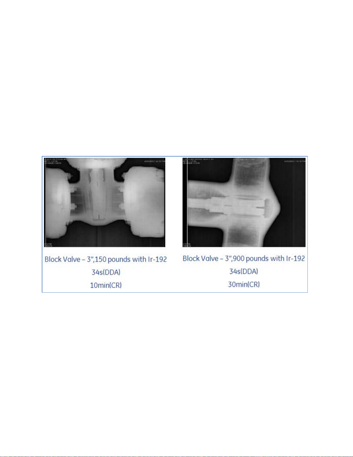
2.1.1 Application Example
There are many examples where DDAs have shown significant benefits over film or
computed radiography. One of these examples is in the oil and gas downstream inspection
of valves. The same inspection plan was completed utilizing both computed radiography
and a DDA. The image quality results were similar or improved utilizing the DDA, but the
exposure time results were remarkably reduced.
Figure 1: Two application examples showing comparing DDA and CR exposure times
2.2 History of DDA Innovation
The medical industry began developing DDA technology over 25 years ago, spending
millions of dollars in the initial 10-year development cycle. Since initial introduction,
technology investment has continued, focusing on two critical areas: image quality for
visualization of relevant features and dose reduction for improved doctor, healthcare
worker, and patient safety. The focus on optimization of image quality with respect to
dose is one of the key aspects leading to the successful implementation into industrial field
applications, where radiation safety is a critical consideration versus environments where
shielding and radiation protection cabinets can be utilized.
2.3 DDA Design Considerations
Page 3

As the first DDAs were developed, there were many design considerations taken into
account as the technology moved from analog to digital. Maintaining the ability to image
in a large format, resolution and the efficiency for converted x-rays to images were primary
considerations in the design process. These requirements translated into specific design
features and choices in the pixel design, scintillator choices and the development of display
electronics to create a DDA with optimized image quality and minimized input dose.
2.3.1 Pixel Design
Each DDA contains millions of individual pixels; the design of those pixels must consider
many elements. A few of the many elements considered during optimization were photodiode
leakage, radiation hardness, electronic noise, x-ray utilization, image size and
manufacturability.
Amorphous Silicon (a-Si) was chosen over Crystalline Silicon (x-Si) technology due to its
elemental structures being less susceptible to radiation damage, the lower leakage characteristic
of the photodiodes and manufacturability, leveraging the equipment and processes developed
by the LCD industry. Using plasma-enhanced chemical vapor deposition (PECVD) the desired
large formats are achieved without the problematic tiling of many smaller x-Si wafers. The
key t rad e-off associated with this choice was speed of the thin film transistors; a-Si can be an
order of magnitude faster.
Choosing optimal pixel size also underwent much consideration. Smaller pixel sizes provide
better resolution; however produce noisier images and require more doses due to fewer x-rays
being captured in the photosensitive diode and smaller fill factors. It became imperative to find
the optimal size allowing the resolution to visualize relevant features for the application while
maintaining high levels of x-ray utilization to minimize dose requirements. Often a 200
micron pixel size is chosen to provide optimization of resolution, noise and dose. However,
some applications require higher resolution to see relevant features and smaller pixels sizes,
such as 100 micron, are chosen factoring in slightly more noise and dose.
2.3.2 Scintillator Options
Two types of scintillators are common across both medical and industrial applications: Cesium
Iodide (CsI) and Terbium-doped Gadolinium Oxysulfide (GdOS:Tb, GOS). CsI is a structured
scintillator vapor deposited as columnar needle-like structures. This shape helps funnel x-rays
efficiently to th e dio de ar ra y; a refl ector i s o ften u sed t o redi rect an y stra y x -rays also aiding in
overall efficiency and image quality. A common drawback to CsI has been its tendency to
“ghost” or display latent images. Some manufacturers have improved this effect through
enhanced formulas and thicknesses. GOS can be a more cos t-effective scintillator choice and
can perform comparably to CsI in terms of x-ray efficiency in some energy ranges. Each
scintillator choice is a viable solution for industrial applications and the user must compare the
trade-offs between cost, efficiency and ghosting. For the oil and gas field applications
discussed, a GOS scintillator was chosen for the oil and gas applications due to cost and
tendency to be utilized in conjunction with isotope sources. In the aerospace aircraft assembl y
applications, a CsI scintillator was chosen for imag e quality and its efficienc y at lower x-ray
energies.
Page 4

2.3.3 Readout Electronics
The readout electronics are responsible for the final conversion of the electrons into useful
digital data. Considerable effort was put into the scintillator and photodiodes to reduce noise
and efficiently utilize x-rays; the readout electronics must continue this through the delivery
and presentation of high image qualit y to the end u ser. Pixels are read out through fast and
complex m ultiplexing, where only micro seconds can be spent reading out each line containing
thousands of pixels. The low leakage in the thin-film transistor (TFT) and low noise highperforming, application-specific integrated circuits (ASICs) are the keys to enable efficient
multiplexing. The ability to maintain a low-noise floor in the electronics allows the design
considerations and choices in the amorphous silicon diode array and scintillator to be realized
in the final image.
2.4 DDA Manufacturing
By choosing Amorphous Silicon for the pixel design, manufacturing DDAs leverage the
processes and equipment from the billion-dollar LCD industry. Beginning with a piece of
glass, the DDA goes through a cyclical process of thin film deposition, photo lithography
pattern and development, pattern etch, pattern strip then finally inspect and test until the
desired number of layers for the pixel design are achieved. The scintillator is deposited either
through vapor deposition or a laminator depending on whether CsI or GOS is chosen. Readout
electronics are then bonded, requiring thousands of connections, to the panel and the unit is
tested as a DDA. After test, the detector is put into final packaging.
3. Conclusions
Many of the design choices and investments made in the medical industry to achieve required
image quality, while keeping the x-ray dose minimal for doctor and patient-safety translate
directly to industry for field applications, where radiation safety is a major concern. The
choices in photodiode, scintillator and electronic technology allow for the efficient conversion
of x-rays leading to the results shown in the ap p l ication examples res ul ts.
 Loading...