

Page 1

GE
Security
P/N DVSR-xU_EN • REV2-23 • ISS 04MAR09
DVSR xU
User manual
Page 2
Copyright © 2009 GE Security, Inc.
This document may not be copied in whole or in part or otherwise reproduced without prior
written consent from GE Security, Inc., except where specifically permitted under US and
international copyright law.
Disclaimer
The information in this document is subject to change without notice. GE Security, Inc.
(“GE Security”) assumes no responsibility for inaccuracies or omissions and specifically disclaims
any liabilities, losses, or risks, personal or otherwise, incurred as a consequence, directly or
indirectly, of the use or application of any of the contents of this document. For the latest
documentation, contact your local supplier or visit us online at www.gesecurity.eu
This publication may contain examples of screen captures and reports used in daily operations.
Examples may include fictitious names of individuals and companies. Any similarity to names
and addresses of actual businesses or persons is entirely coincidental.
Trademarks and patents GE and the GE monogram are trademarks of General Electric Company.
Other trade names used in this document may be trademarks or registered trademarks of the
manufacturers or vendors of the respective products.
Intended use
Use this product only for the purpose it was designed for; refer to the data sheet and user
documentation for details. For the latest product information, contact your local supplier or visit
us online at www.gesecurity.eu
Certification and compliance
European Union directives
1999/5/EC (R&TTE directive): Hereby, GE Security declares that this device is in compliance with
the essential requirements and other relevant provisions of Directive 1999/5/EC.
2002/96/EC (WEEE directive): Products marked with this symbol cannot be disposed of as
unsorted municipal waste in the European Union. For proper recycling, return this product to
your local supplier upon the purchase of equivalent new equipment, or dispose of it at
designated collection points. For more information see: www.recyclethis.info
2004/108/EC (EMC directive): Non-European manufacturers must designate an authorized
representative in the Community. Our authorized manufacturing representative is:
GE Security B.V., Kelvinstraat 7,
6003 DH Weert, The Netherlands.
2006/66/EC (battery directive): This product contains a battery that cannot be disposed of as
unsorted municipal waste in the European Union. See the product documentation for specific
battery information. The battery is marked with this symbol, which may include lettering to
indicate cadmium (Cd), lead (Pb), or mercury (Hg). For proper recycling, return the battery to your
supplier or to a designated collection point. For more information see: www.recyclethis.info
Contact information For contact information see our Web site: www.gesecurity.eu
.
Page 3

i
Content
1. Product overview ......................................................................................................................1
Product description ................................................................................................................................................................................ 1
Unpacking the DVSR xU and its accessories.............................................................................................................................. 1
Installation environment...................................................................................................................................................................... 2
2. DVSR xU installation .................................................................................................................3
Connecting the devices ........................................................................................................................................................................ 3
Connecting alarm inputs and outputs........................................................................................................................................... 4
Connecting the DVSR xU to a PC...................................................................................................................................................... 4
Turning on the DVSR xU........................................................................................................................................................................ 5
3. Controlling the DVSR xU ..........................................................................................................6
Using the front panel............................................................................................................................................................................. 7
Using the IR remote control................................................................................................................................................................ 9
Using the mouse....................................................................................................................................................................................10
Using the Web browser......................................................................................................................................................................11
4. Basic operations..................................................................................................................... 12
Login using PINs.....................................................................................................................................................................................12
Description of live mode.....................................................................................................................................................................12
Selecting live view .................................................................................................................................................................................14
Manual recording ..................................................................................................................................................................................15
Searching and playing back recorded video............................................................................................................................16
Archiving recorded files......................................................................................................................................................................19
Controlling a PTZ camera ..................................................................................................................................................................24
Overview of the menu structure.....................................................................................................................................................26
Turning off the DVSR xU .....................................................................................................................................................................29
5. Display settings...................................................................................................................... 30
Configuring the display settings.....................................................................................................................................................31
6. Camera settings..................................................................................................................... 36
Configuring camera settings............................................................................................................................................................37
7. Recording settings................................................................................................................. 49
Configuring the recording settings ...............................................................................................................................................49
8. Network settings.................................................................................................................... 56
Configuring the network settings...................................................................................................................................................57
9. Alarm settings ........................................................................................................................ 63
Alarm relay outputs..............................................................................................................................................................................63
Configuring the alarm settings .......................................................................................................................................................64
10. PTZ settings............................................................................................................................. 69
Description of preset, preset tour, and shadow tour options...........................................................................................70
Configuring the PTZ protocols of GE Security cameras.......................................................................................................70
Configuring the PTZ settings ............................................................................................................................................................71
Page 4

ii
11. User settings ........................................................................................................................... 76
Overview of users and PINs..............................................................................................................................................................77
Configuring the user settings...........................................................................................................................................................78
12. System settings...................................................................................................................... 82
Capturing text insertions....................................................................................................................................................................83
Configuring the system settings.....................................................................................................................................................85
13. Troubleshooting and support.............................................................................................. 94
Troubleshooting your system..........................................................................................................................................................94
Contacting technical support ..........................................................................................................................................................95
Appendix 1: Specifications ............................................................................................................. 96
DVSR xU Menu Map........................................................................................................................ 100
Page 5

DVSR xU User Manual 1
1. Product overview
Product description
The second generation of DVSR uses H.264, the latest video compression standard. This standard
offers 25 frames per channel per second at CIF resolution. This compression technology delivers
compact but excellent quality images.
The DVSR xU offers 4, 8 or 16 channels of analog recording, all up to 4CIF resolution (704 x 576). The
dual streaming functionality allows the user to set up different settings for recording and streaming
video. DVSR xU supports both variable bit rate and variable frame rate. The dual streaming
functionality allows the user to set up different settings for recording and streaming video. DVSR xU
incorporates Triplex functionality for simultaneous transmitting, viewing live video, and recording.
The DVSR xU series embedded digital video recorder is a digital surveillance product. It uses an
embedded microcontroller DVSR xU (MCU) and an embedded real-time operating system (RTOS),
combining the most advanced technology in the information industry, such as video and audio
encoding/decoding, hard disk recording, and TCP/IP. The firmware is burned into the flash, making it
more stable and reliable.
DVSR xU series has the features of both a digital video recorder (DVR) and a digital video server (DVS).
It can be used as a standalone device but also to build a powerful surveillance network, such as
widely used in the banking, telecommunications, manufacturing, and transportation sectors.
Unpacking the DVSR xU and its accessories
When you receive the product check the package and contents for damage, and that all the items
are included. There is an item list in the package. If any of the items are damaged or missing, please
contact your local supplier.
Page 6
2 DVSR xU User Manual
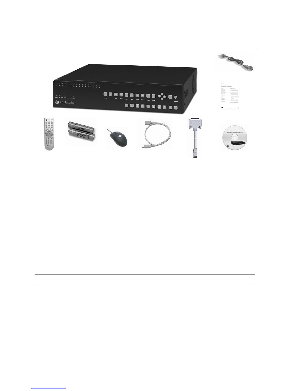
Figure 1: Items shipped with product
AC mains cable
QuickStart Guide
IR remote
control
AAA batteries USB mouse USB extension cable RS-232 cable CD with
documentation &
utilities
Installation environment
Ventilation: Do not block any ventilation openings. Install in accordance with the manufacturer’s
instructions. Ensure that the location planned for the installation of the unit is well ventilated.
Regularly clean the unit by gently brushing it.
Temperature: Consider the DVSR xU’s operating temperature (-10 to 50°C) and non-condensing
humidity specifications (10 to 90%) before choosing an installation location. Extremes of heat or cold
beyond the specified operating temperature limits may cause the DVSR xU to fail. Do not install the
DVSR xU on top of other hot equipment. Leave space between rack mounted DVSR xUs.
Moisture: Do not use the unit near water. Moisture can damage the internal components. To reduce
the risk of fire or electric shock, do not expose this unit near to rain or moisture.
Chassis: Other equipment may be placed on top of the DVSR xU if it weighs less than 16 kg.
WARNING: Before installing the DVSR, please ensure that the power to the DVSR is switched off.
Page 7
DVSR xU User Manual 3
2. DVSR xU installation
This section describes how to connect the DVSR xU unit.
Connecting the devices
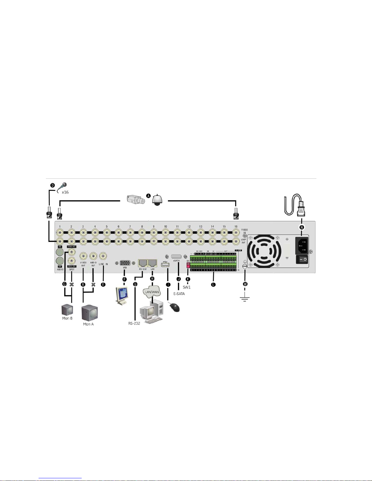
Figure 2 shows the back panel connections and describes each connector. There are variations
between the different model types.
Figure 2: DVSR16 xU back panel connections
Required connections
A. Connect up to 16 cameras to the standard BNC video inputs.
Note: If a camera is incorrectly connected to the DVSR xU, the monitor shows a Video Loss message. Check the
connection and reconnect the camera if necessary.
B. Connect monitor A (main) to the output VIDEO OUT. Connect the audio output () to AUDIO OUT if required. You can
use either analog or VGA output. Both outputs will display the same video information.
Optional connections
C. Connect a spot monitor (Mon B) to the DVSR xU. Connect the monitor video to VIDEO OUT. Connect the monitor audio
(if used) to AUDIO OUT ().
D. Connect up to 16 audio signals to the standard BNC audio inputs (315 mV).
E. For future use.
F. Connect the VGA display (max. 1024 × 768 @ 60 Hz).
G. Connect an ATM or optional ProBridge using the supplied RS-232 cable.
H. Connect the network devices.
I. Connect the USB mouse (supplied).
J. Connect the E-SATA for archive and storage expansion.
Page 8
4 DVSR xU User Manual
K. Terminate the line using this RS-485 switch. The default setting is OFF.
L. Connect the external data and alarm input/output (I/O) cable. See Figure 3 on page 4 for more information.
M.
Connect the DVSR xU to ground.
Power connection
N. Connect the power cord to the DVSR xU. Be sure all devices are connected and turned on before you turn on the
DVSR xU.
Connecting alarm inputs and outputs
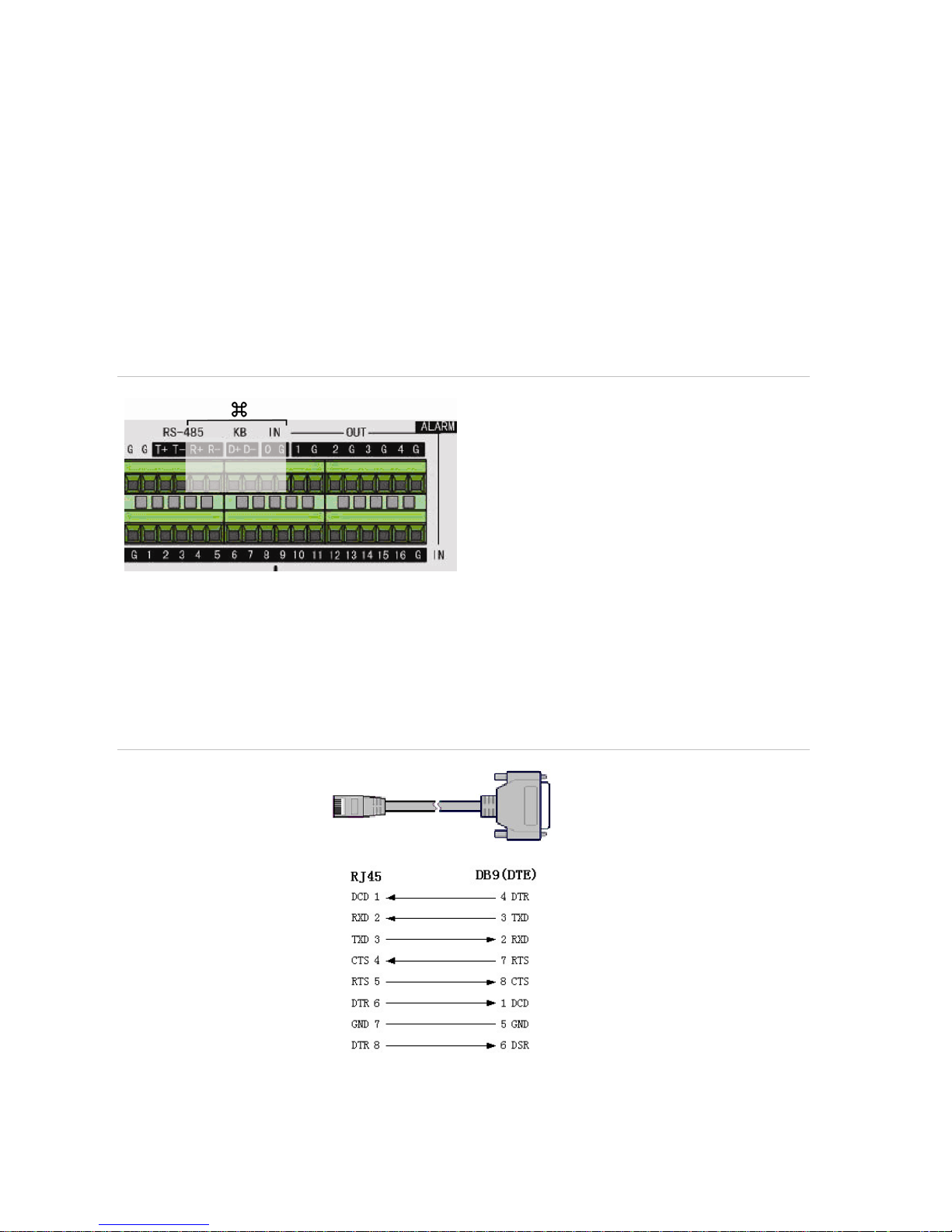
Figure 3: Connecting the external data and alarm I/O cable
: Not used
RS-485 T+ T-: Connect PTZ camera data
Alarm output port:
1-G to 4-G: 4 relay ports
Alarm input port:
G: Common ground)
1 to 16: Alarm inputs, NO/NC supported
Connecting the DVSR xU to a PC
Use a RS-232 cable to connect the unit to a PC. Figure 4 describes the pin connections to use when
connecting the serial port of the DVSR to a device using a DB9 connector such as on a PC.
Figure 4: The pin connections of a RS-232 cable
DVSR xU
PC
Pin configuration
Page 9

DVSR xU User Manual 5
Turning on the DVSR xU
The DVSR xU is delivered with preconfigured settings. You only need to connect the cameras and the
monitors. After powering up, the DVSR xU will start to record immediately.
Note: The default video standard is PAL. For information on changing the standard, see section To select the
video standard on page 32.
The DVSR xU is equipped with a universal power supply that will auto-sense 100/240 V, 60/50 Hz.
Turn on the connected equipment. When you turn on the DVSR xU it automatically displays all
connected cameras. The DVSR xU shows the number of HDDs installed then displays live views from
each connected camera. It automatically begins recording.
To get the unit into operation quickly
1.
Connect all the devices required to the back panel of the DVSR xU. See Figure 2 on page 3.
2.
Turn on the unit. The unit automatically carries out a diagnostic test of the devices. The video
images then appear onscreen.
3. To modify the preconfigured settings, press the Menu button on the front panel to access the
main menu. The login dialog screen appears.
4. Enter the default administrator user ID and PIN. The main screen appears.
User ID = Administrator
PIN = 3477
5. Modify the DVSR xU parameters as required in the submenus.
6. When customization is complete, press Esc to exit menu mode and return to live mode.
Page 10

6 DVSR xU User Manual
3. Controlling the DVSR xU
There are four ways to control the DVSR xU menu options:
Front panel control
IR remote control
Mouse control
Web browser control
These options are described in the following sections.
Page 11
DVSR xU User Manual 7
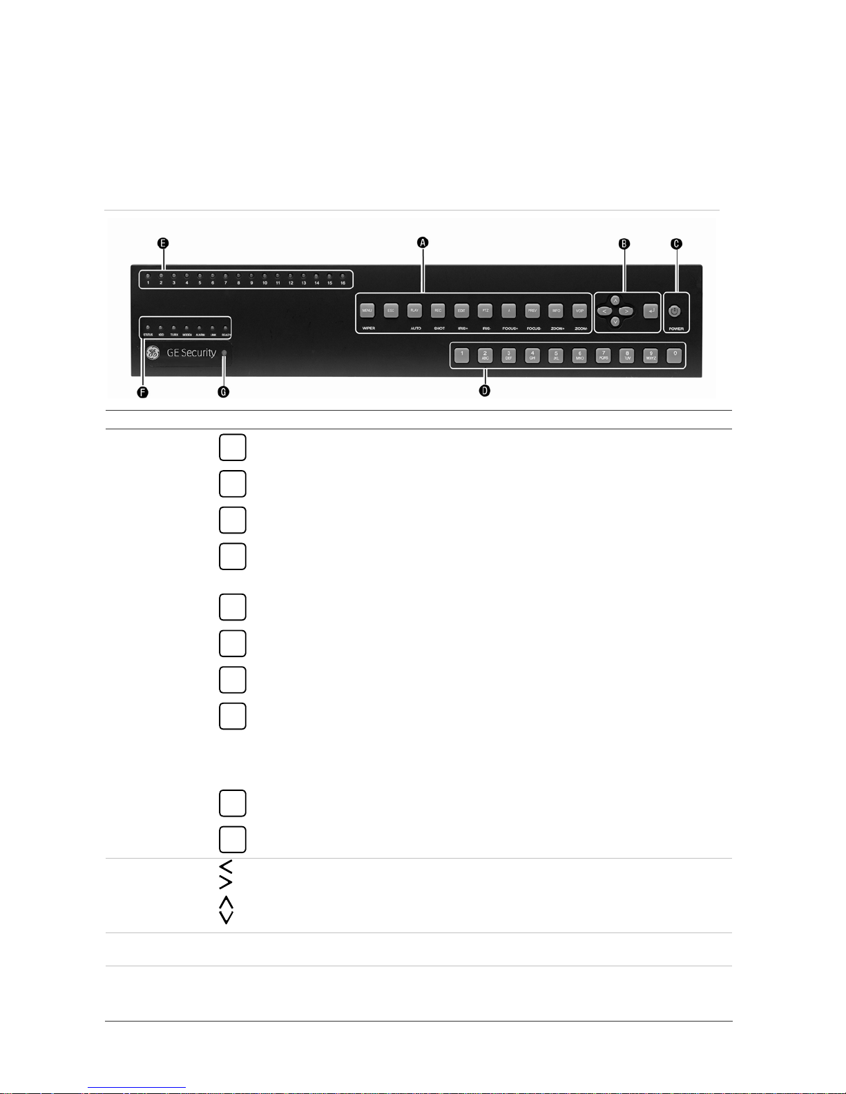
Using the front panel
The buttons on the front panel control all functions. The LED indicators light up or flash to alert you to
various conditions. See Figure 5.
Figure 5: Description of the DVSR xU front panel
Buttons Description
A. Function
MENU
Main menu button. Opens the programming menus.
ESC
ESC button. Cancels the current operation and returns to the previous menu.
PLAY
Playback button. Opens the Search menu to search for recorded video files.
REC
Record button. Opens the manual record menu.
The privileged user can then start, select, deselect, or stop manual recording for each video
channel.
EDIT
Edit button. A multifunctional button. Its function depends on the current usage of the unit.
PTZ
PTZ button. Activates the PTZ control of the selected camera, if PTZ is supported.
A
Input method button. In an alphanumeric window, toggles through the different character
types. In live mode, activates or deactivates the status bar.
PREV
Preview button.
- Cycle through the multiscreen displays. Inactive cameras display NO VIDEO SIGNAL..
- Switch from Cycles through the multiscreen displays. Inactive cameras display No Video
Signal.
- Switches from any menu to return to viewing live video.
INFO
System information button. Information. For future use.
VOIP
VOIP button. Toggles between monitors A and B.
B. Direction
controls
- Arrow buttons move the cursor in the programming menus to select and change settings.
- If the PTZ option is activated, the arrows control the PTZ camera.
- Control the playback video.
C. POWER Power switch. Press the button for at least 5 seconds to turn off the DVSR xU. You will be asked for
your PIN.
D. Alphanumeric Select video channels.
Select full-screen display for the selected channel.
Enter text and numbers in programming submenus.
Page 12

8 DVSR xU User Manual
LED Description
E. Channels Green indicates recording.
Red indicates remote viewing.
Orange indicates both recording and remote viewing.
F. Status Status: Green indicates that the unit is linked to an IR remote control.
HDD: Red indicates that the DVSR xU is accessing the HDD.
TX/RX: Flashing green indicates data transmission.
Modem: Green indicates that the unit is currently connected to a network.
Alarm: Steady red indicates an alarm.
Link: Green indicates that the unit is linked to a network.
G. IR remote
receiver
This is the receiver for the IR remote control.
C. Power Steady green indicates DVSR xU is operational.
Red indicates manual shutdown.
No light indicates that there is no power.
To silence the audible button feedback
At any time press and hold down the MENU button for at least
five seconds. The audible button
feedback will activate or deactivate depending on the current status. Press ESC to return to the live
viewing screen.
Page 13
DVSR xU User Manual 9
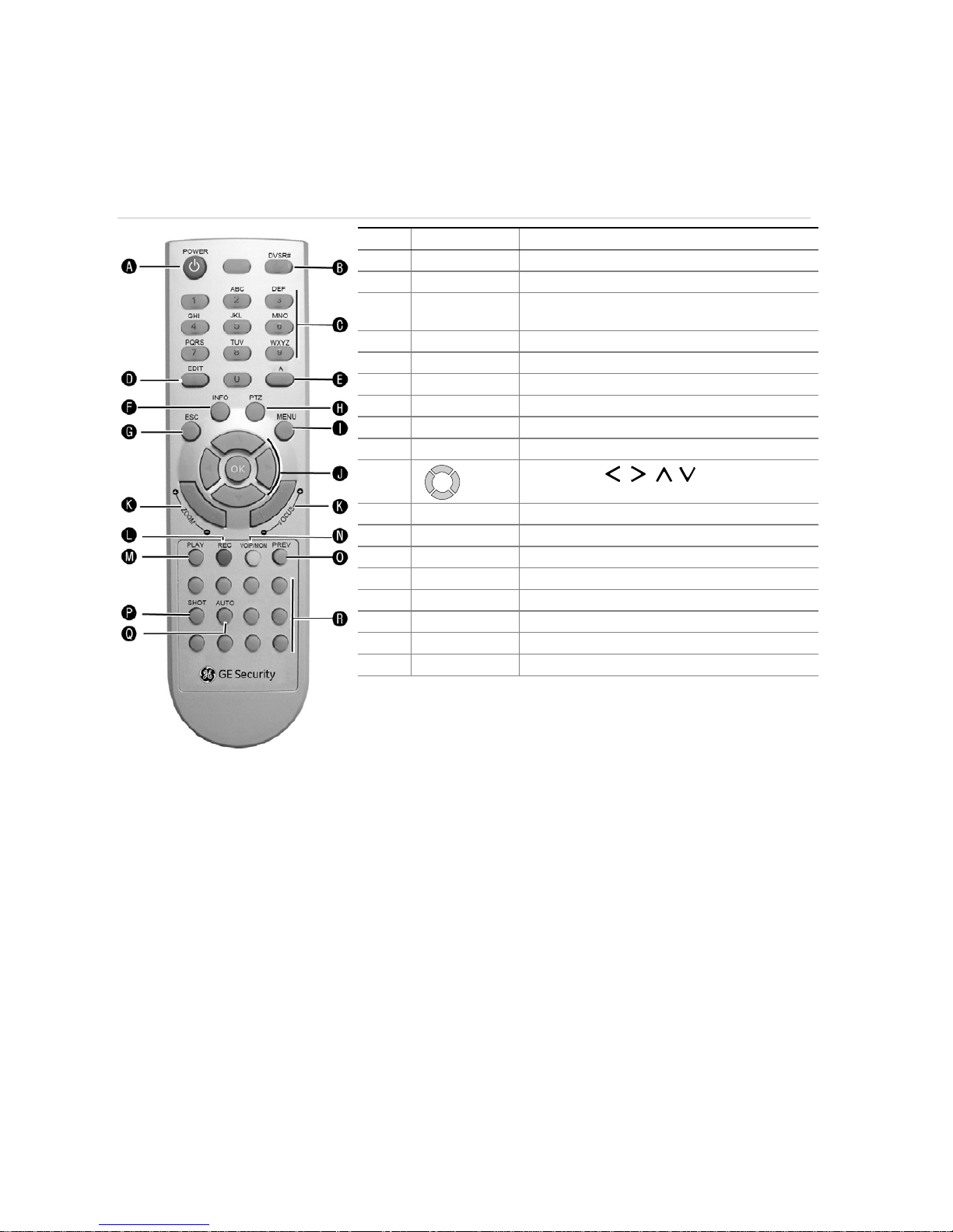
Using the IR remote control
The IR remote control operation is similar to front panel operation.
Figure 6: Description of the IR remote control
No. Name Description
A. POWER Turn the DVSR on/off.
B. DVSR# Enable/Disable the IR remote control
C.
Alphanumeric
buttons
Same as the alphanumeric button on the front
panel
D. EDIT Same as the EDIT button on the front panel
E. A Same as the A button on the front panel
F. INFO Same as the INFO button on the front panel
G. ESC Same as the ESC button on the front panel
H. PTZ Same as the PTZ button on the front panel
I. MENU Same as the MENU button on the front panel
J.
OK
Same as the
, , , buttons and the
Enter button on the front panel
K. Lens control IRIS, FOCUS ZOOM for lens control
L. REC Same as the REC button on the front panel
M. PLAY Same as the PLAY button on the front panel
N. VOIP/MON Same as the VOIP button on the front panel
O. PREV Same as the PREV button on the front panel
P. SHOT Same as the REC-SHOT button on the front panel
Q. AUTO Same as the PLAY-AUTO button on the front panel
R. Reserved
To insert batteries into the IR remote control
1. Remove the battery cover on the remote control.
2. Insert the batteries. Observe the correct battery polarity (+ and -).
3. Replace the battery cover.
To connect the remote control to the DVSR xU:
1. Press the DVSR# button on the remote control.
2. Enter the device ID. The DVSR xU default ID is 1.
Note: See page 31 on how to change the device ID.
3. Press OK. The Status LED will light up on the DVSR xU front panel.
To switch off the IR remote control
1. When IR remote control STATUS LED on the DVSR front panel is lit, press the DVSR# button. The
STATUS LED switches off and the IR control cannot be used to operate the DVSR.
Page 14

10 DVSR xU User Manual
To switch off the DVSR with the remote control
1. When IR remote control STATUS LED on the DVSR front panel is lit, press the POWER button for
several seconds. The DVSR will be switched off.
When the IR remote control does not function properly
Check the battery polarities
Check that the batteries are sufficiently charged
Check that the IR remote control sensor is not masked
If the problem persists, please contact your local supplier.
Using the mouse
Use the USB mouse provided with the DVSR xU. It can carry out the same operations as the front
panel and remote control.
Connect the mouse to the DVSR by simply plugging the mouse USB connector into the USB port on
the back of the DVSR xU. The mouse is immediately operational.
To use it in live view
1. Scroll forwa
rds and backwards between cameras: When in full-screen view use the scroll button
on the mouse to scroll forwards and backwards through the cameras.
Toggle between full-screen and multiview: When in multiview double-click the left button of the
mouse on a camera to open it in full-screen view. Double-click again to return to multiview.
To access the mouse control menu
1.
In live view right-click the mouse to open its control menu. It has eight menu options, which are
listed in Table 1.
Table 1: Mouse control menu
Menu option Description
Menu Jump to the main menu.
Camera Select a specific individual camera.
Multi Screen Select multiview. The multiview selection presented depends on the number of
cameras connected to the DVSR.
PTZ Control Control a PTZ camera. See Table 4 on page 25 for the description of the PTZ control
icons.
Right-click the mouse to get the following options:
• Channel: Select the camera to control
• Preset: Select a preset number to use
• Exit: Return to live view
Instant Replay Get an instant replay of the last five minutes recorded from all cameras in either full-
screen view or multiview. See section To playback a recorded file on pa
ge 18 for more
information.
During the playback, right-click the mouse to jump to the Playback menu.
Search Jump to the Playback menu. See Fig 12 on page 17. Select for recordings with specific
criteria, such as particular camera, type of event, time, and text.
Right click mouse to return to live view.
Page 15
DVSR xU User Manual 11
Menu option Description
Manual Record Manual Record menu screen appears. See Fig 11 on page 16.
Status Bar Toggle onscreen status bar on/off.
Swap Monitor Toggle between monitors A and B.
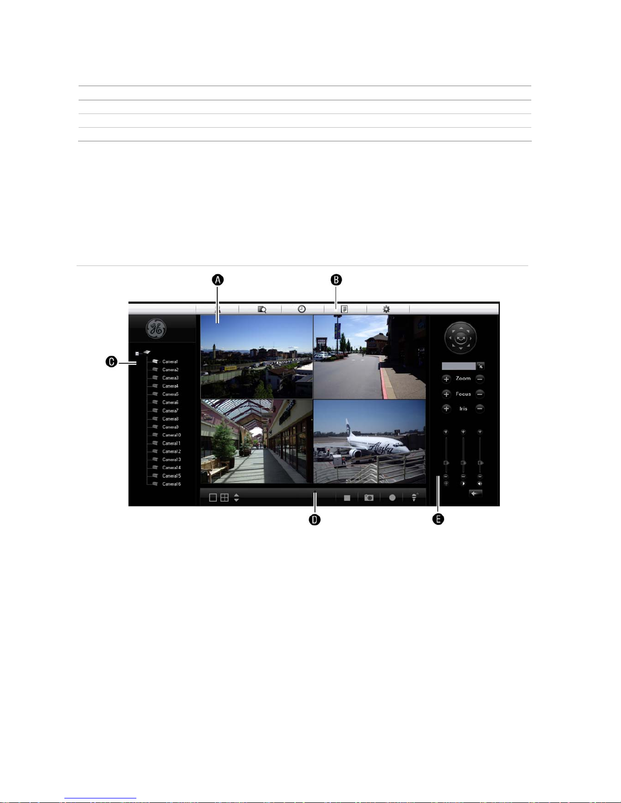
Using the Web browser
The DVSR xU Browser lets you easily view, record, and playback video as well as manage all aspects of the
system from any Internet location. It has easy-to-use controls that give you quick access to the functions you
require. See Figure 7 below for the layout.
F
igure 7: DVSR xU Browser layout (Live view shown)
A. Viewer: View live and recorded video.
B. Navigation bar: Access live and playback video. Explore the DVSR xU internal log, and carry out comprehensive
remote maintenance.
C. Navigator: Access all DVSR xU cameras.
D. Viewer controller: View or edit the properties of the currently selected objects in the Navigator.
E. Camera controller: Control PTZ cameras or edit properties of the currently selected cameras.
To access the DVSR xU Browser
Open Internet Explorer and type the IP address assigned to the DVSR xU. In the Login screen enter the
user ID and PIN.
User ID = Administrator
PIN = 3477
Page 16

12 DVSR xU User Manual
4. Basic operations
This chapter describes the everyday usage of the DVSR xU. It explains:
Login using PINs
Live mode
Full and multiscreen mode
Manual recording
Searching and playing back video
Archiving recorded files
Controlling a PTZ camera
Overview of the menu structure
Turning off the DVRS xU
Login using PINs
Use PINs to limit access to the DVSR xU. Only authorized users should be able to modify menu
settings or carry out certain tasks. See section User settings on
page 76 for information on managing
users.
Note: You will hear an aud
ible warning when an incorrect user name or PIN is entered. After three
incorrect entries, the unit returns to live mode.
Description of live mode
In live mode, you watch live video from a camera. Live mode is the normal operating mode of the unit.
From live mode you can switch to playback mode or to the system menu.
The way the monitors display video depends on how you set up the system.
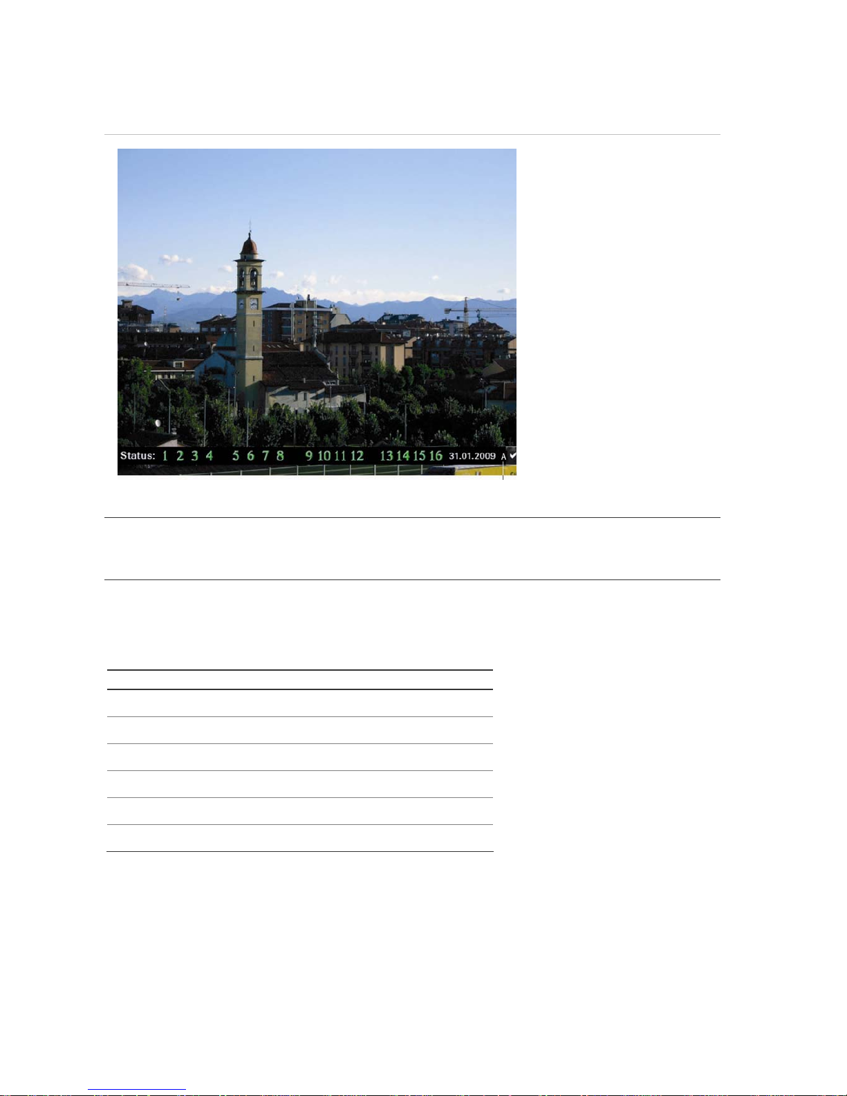
In live mode, the DVSR xU displays the status of each video channel at the bottom of the screen. See
Figure 8. The number of channels displayed (4, 8, or 16)
depends on the DVSR xU model.
Page 17
DVSR xU User Manual 13
Figure 8: Example of live mode with recording status displayed (for 16 cameras)
If the letter is grey letter, the monitor is inactive
Caution: DVSR xU has no camera autodetection mode. The unit records a channel even if no camera
is connected to it. A black picture with the message "Video Loss" is displayed when the channel is
selected in either live mode or playback mode.
The color of the camera numbers displayed in the status bar represents the channel status. It is
consequently easy to see the current status of each channel during live mode. The status color code
is described in Table 2.
Table 2 Description of the status color code
Icon Icon color Status description
1
Blue No video signal
1
Yellow Camera tampered
1
Grey Camera disabled
1
Green Real time recording
1
Orange Motion detection
1
Red External alarm
The status bar can be set to appear by default. See section To setup the status bar on page 32.
Page 18
14 DVSR xU User Manual
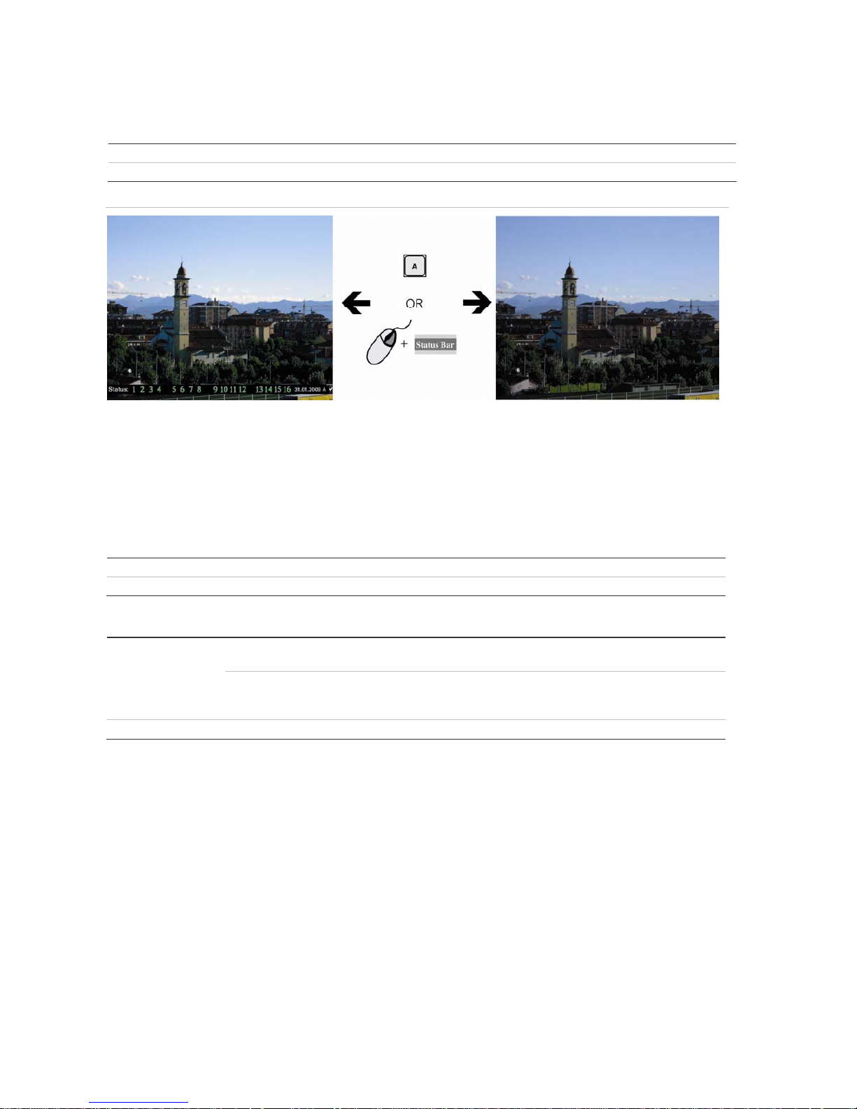
To activate/deactivate the onscreen status bar
Front panel/remote control Press the A button on the front panel to activate or deactivate the status bar.
Mouse Right-click the mouse and select Status Bar from the menu.
Figure 9: Activate or deactivate the status bar
Selecting live view
You can select from which monitor to display the camera views in live mode as well to display full or
multiview screens on the monitor.
To select between monitor A and B
Front panel/remote control Press the VOIP button to select between monitor A and B.
Mouse Right-click the mouse and select Swap Monitor from the menu shown.
To view a full screen display
Front panel/
remote control
DVSR xU with 4 or 8
cameras:
Press the number button that corresponds to the camera number.
For example, press button 2 to preview camera number 2.
DVSR xU with 16
cameras
Press the two number buttons that correspond to the camera
number. For example, press buttons 0 2 to preview camera
number 2, and press buttons 1 2 to preview camera number 12.
Mouse Right-click the mouse and select Camera from the menu shown. Select the camera you need.
Page 19
DVSR xU User Manual 15
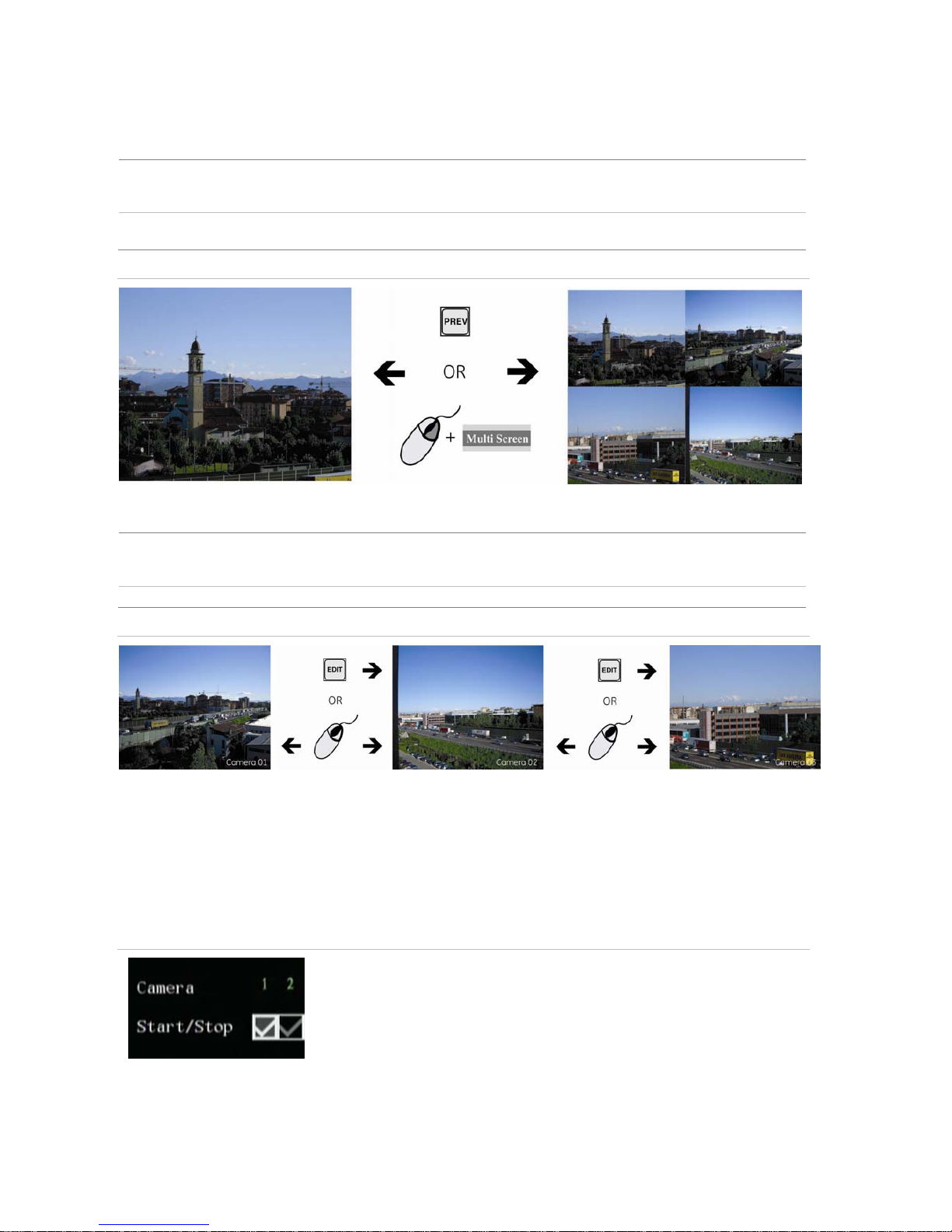
To view a multiscreen display
Front panel/remote control Press the PREV button to switch to multiscreen live viewing. If the multiscreen
display does not include all the cameras you want to see, keep pressing the PREV
button to increase the number of screens displayed.
Mouse Right-click the mouse and select Multi Screen from the menu. Select the desired
display layout.
Figure 10: Change the number of screens on view
To manually cycle through live views
Front panel/remote control Press the EDIT button to manually step through the live views. You can set the auto
multiscreen mode in the Display menu. See section To change live view layout on
page 33 for further information.
Mouse Use the mouse wheel to scroll forwards and backwards through the live views.
Figure 11: Manually cycle through live views
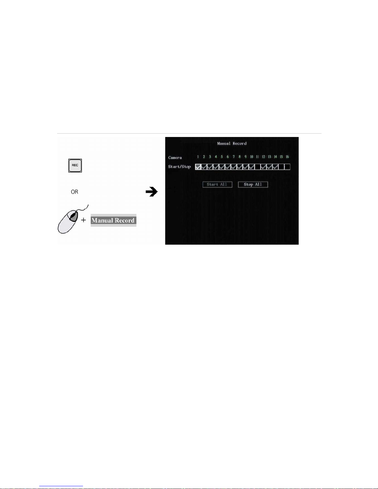
Manual recording
When a channel is recording its corresponding LED on the front panel is green. This green LED is also
repeated in the manual record menu. You can start or stop a channel recording by pressing the REC
button and entering into the Manual Record menu.
Figure 12: What the options mean in the Manual Record menu
When the status of the camera number is:
• Green indicates the channel is recording
• Red indicates remote viewing
• Orange indicates both recording and remote viewing
• Grey the channel is not recording
Start/Stop options:
• indicates recording is enabled
Page 20
16 DVSR xU User Manual
To manually start or stop a recording
1. Press the REC button on the front panel of the DVSR or the IR remote control, or right-click the
mouse, and select Manual Record. Enter your user name and PIN, if requested.
Note: You must have Record rights to change the manual recording status. See section To add or modify
user operational rights on page 79 for more information.
The manual record screen appears, listing all the channels. The Camera status line shows which
channels are currently recording. See Figure 13.
Figure 13: The manual record menu with 16 channels (13 recording)
2. On the Start/Stop line press Enter or left-click the mouse to activate () a channel that is not
recording. Press or click again to de-activate.
The channel status LED on the front panel and the camera number in the status bar on screen
turn green. The Start/Stop button in the Manual Record screen displays a “”.
Recording now starts from the selected channel.
3. Select the next channel from which you want to start or stop recording.
4. If you want all channels to start recording, select Start All. All the channel status LEDs on the front
panel and the onscreen camera numbers in the status bar turn green.
Select Stop All to switch off all channels.
5. Press the ESC button or right-click the mouse to save changes and return to the live mode.
Searching and playing back recorded video
You can search for and playback recorded video. You must be in live mode to playback video. You can
search recorded videos by several different options, such as:
Manually, motion detection, or alarm recorded files
Start and end time of recording
Text (from an ATM, for example)
Page 21
DVSR xU User Manual 17
Note: You must have playback rights to playback recorded images. See section To add or modify user
operational rights on page 79 for more information.
The system also lets you playback channels simultaneously so that multiple images appear onscreen.
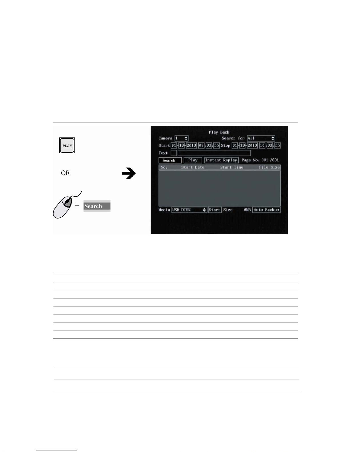
To search for recorded video
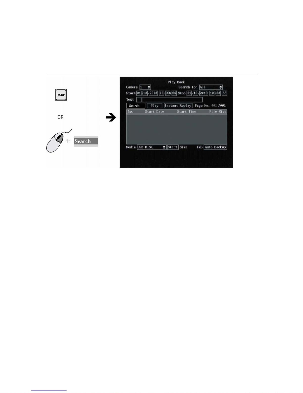
1.
In live mode press the PLAY button on the front panel of the DVSR xU or the IR remote control, or
right-click the mouse and select Search. Enter your user name and PIN, if requested. The playback
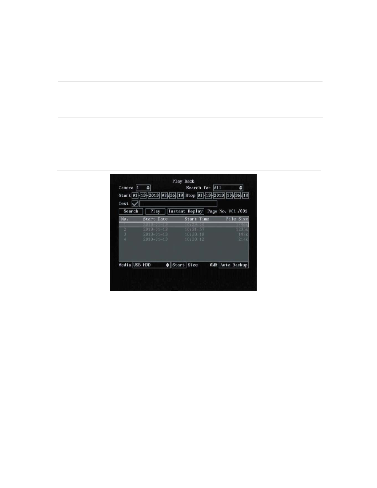
menu appears. See Figure 14.
Figure 14: The Playback menu
2. In the Camera list box select the channel you want to search.
3. In the Search for list box select the type of recorded videos to be searched. See Table 3.
Table 3 Video type options
Option Search for recorded file types
All All recordings
All Time Only scheduled time recorded files
Manual Only manually recorded files
Alarm Only alarm recorded files
Motion Det. Only motion detected files
Motion & Alarm Only files where motion and alarm were detected at the same time
Motion | Alarm Only files where motion or alarm was detected
4. For the Start and Stop recording periods go to each edit box and enter the start and end dates
and times:
Front panel or remote
control
Press EDIT. Use the arrows buttons to change the numeric value. Press Enter
when completed and move to the next edit box.
Mouse Click the edit box and select the number from the onscreen numeric list that
appears.
Note: The date has the format DD-MM-YYYY. Time has a 24-hour format. The default stop values shown are
the current time and date.
Page 22
18 DVSR xU User Manual
5. If you want to search for video from a particular ATM, for example, go to Text and press Enter or
left-click the mouse to activate (). In the edit box alongside the check box type the text to be
searched (for example, the text that appears on an ATM screen.)
Front panel or remote
control
Press EDIT. Press A to change the type of character to be entered, which is shown
on the bottom of the screen. Use the alphanumeric buttons to enter the text. Press
Enter when completed.
Mouse Click the edit box and select the text from the onscreen alphanumeric list that
appears.
6. Go to Search and press Enter or left-click the mouse to start the search.
When the search is completed a list of all the files found appears. The list may extend over several
pages. The most recent file is listed first. See Figure 15 for an example of a search result.
Figure 15: Example of a search result
Note: If you get a message saying that there are no recordings but you were expecting some to be listed,
check that you have selected the correct recorded file type option for your search.
7. Press ESC or right-click the mouse to quit playback mode and return to live mode.
To playback a recorded file
1.
Search for the files you want to playback. See section To search for recorded video on pag
e 17.
2. In playback mode (see Figure 15 on page 18) there are three ways to playb
ack a recorded file:
a. Select Play. The system will play each file listed, starting with the first file.
— or —
b. In the search window select the video file you want to play and press Enter or left-click the
mouse. Only the selected file will be played back.
— or —
c. Select Instant Replay and press Enter or left-click the mouse. The system will play the last 5
minutes recorded by the selected camera.
Page 23
DVSR xU User Manual 19
3. Press ESC or right-click the mouse to return to the Play Back menu. All the files you selected for
playback are now deselected.
4. Press ESC again or right-click the mouse to quit playback mode and return to live view.
Archiving recorded files
You can archive recorded files on external devices. As well as being able to archive a complete
recorded file, you can also archive specific incidents in a file. You must be in live mode to playback a
recorded file.
Note: You must have playback rights to playback recorded images. See section To add a new user on page 78
for more information. Avoid moving the external recording device when backing up information onto it.
Description of the Playback toolbar
A toolbar appears on screen during playback to help select the portions of recordings to be archived.
It also displays playback progress.
There are two parts to the toolbar. The top row of icons let you control how you playback the video
and what portions to archive. See Figure 16. The icons are controlled using the mouse.
The bott
om row shows you the playback progress and speed. See Figure 17.
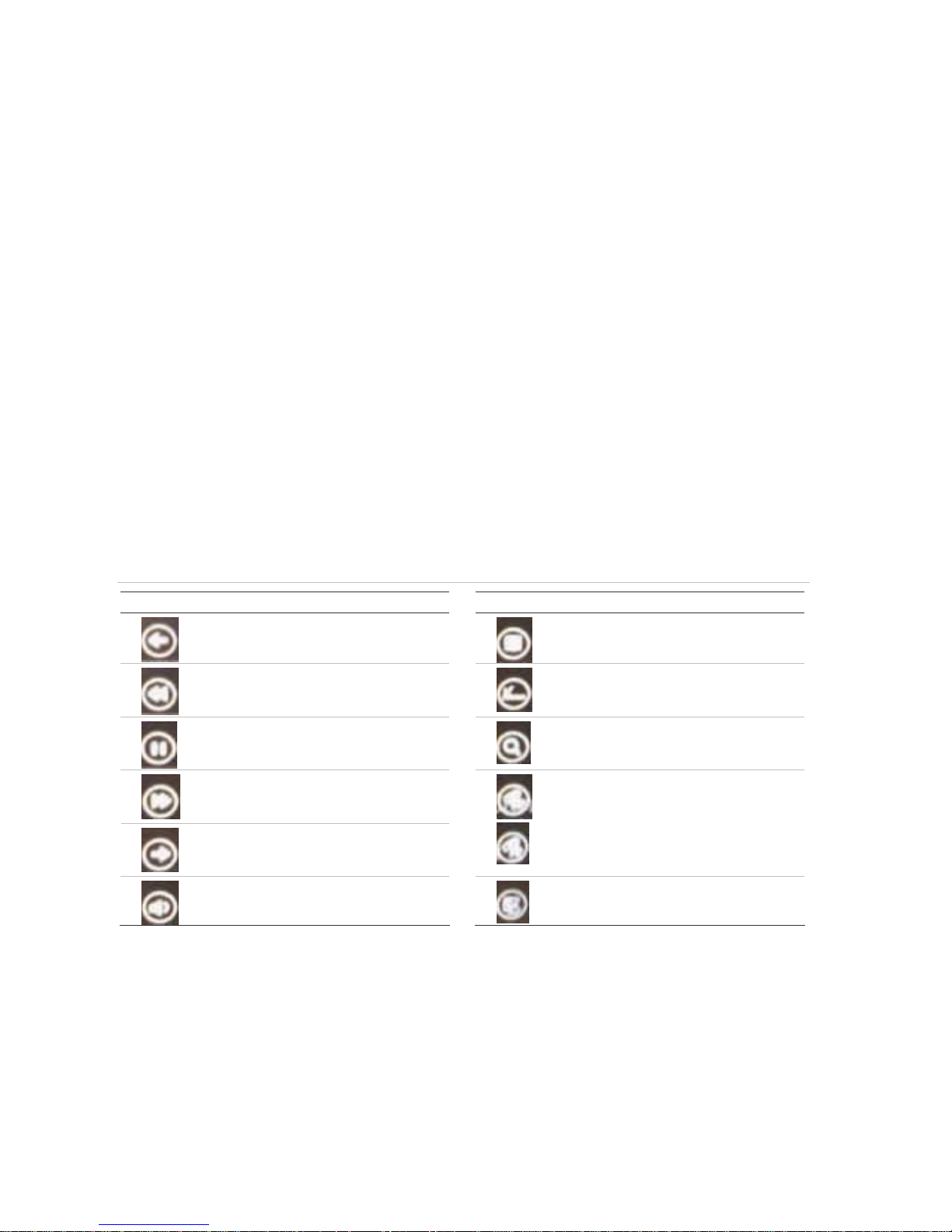
Figure 16: Description of the Playback toolbar icons
Icon Description
Icon Description
Jump back 30 seconds in the playback
video.
Start archiving the video.
Decrease the playback speed. See
Figure 17 for the list of speeds
available.
Remove the Playback toolbar. To make it
reappear onscreen, right-click the mouse
and select Display.
Pause the playback.
Digital zoom. Double left-click the mouse
to zoom in. Double left-click again to
return to normal view.
Increase the playback speed. See
Figure 17 for the list of speeds
available.
Jump forward 30 seconds in the
playback video.
To view full screen when in multiscreen
mode, double-click the mouse on the
desired screen. It appears as full screen.
Left-click the mouse on one of the icons
to move backwards or forwards through
the full screens.
Turn on or off audio.
Left-click the mouse to scroll through the
number of multiscreens displayed.
Page 24
20 DVSR xU User Manual
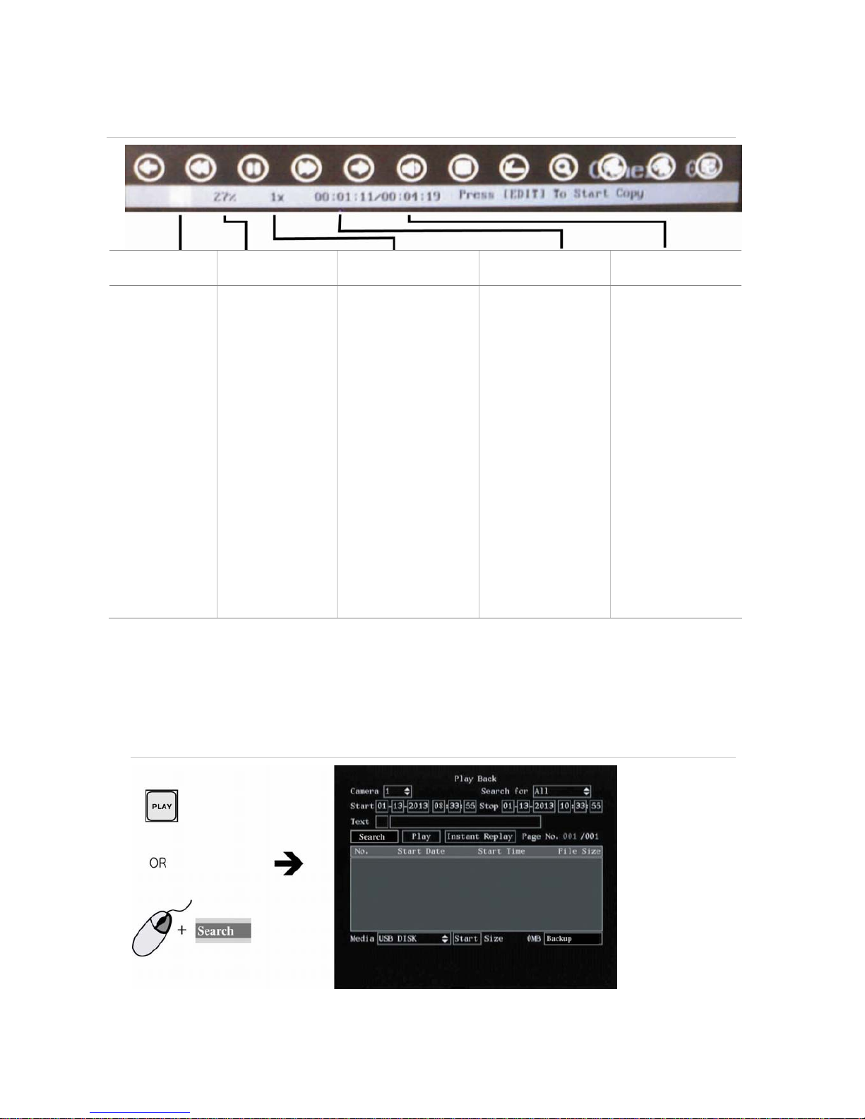
Figure 17: Playback information on a recorded file
Audio Playback progress Playback speed
Current playback
time
Total playback time
Press PLAY to
silence the audio
recording
associated with
this video. Press
PLAY again to
reactivate the
audio.
Audio in this
example is on.
Shows how far you
have progressed
through the
recorded file.
Press the arrow buttons
to change the rate of
playback. Nine options
are available:
Single: Press Enter to
advance one frame at a
time.
1/8x: An eighth of
actual speed.
1/4x: Quarter of actual
speed.
1/2x: Half of actual
speed.
1x: Actual speed.
2x: Twice actual speed.
4x: Four times actual
speed.
8x: Eight times actual
speed.
MAX: Maximum speed.
Playback always
starts from time zero.
The actual time of the
recording is shown
on the top of the
screen.
Press the arrow
buttons to jump
backwards 30
seconds, or to jump
forwards 30 seconds.
Shows the duration of
the recorded file. In
this example, it is 4
minutes 19 seconds.
To archive a recorded file
1. In live mode press the PLAY button on the front panel of the DVSR or the IR remote control, or
right-click on the mouse and select Search. Enter your user name and PIN, if requested. The
playback menu appears. See Figure 18.
Figure 18: The Playback menu
Page 25

DVSR xU User Manual 21
2. Search for the recorded files you want to copy. See To search for recorded video on
page 17 for
more information.
3. Press the EDIT button or left-click the mouse to select the video file you want to copy from the list.
The file will be highlighted.
4. Select other files you want to archive. Each selection must be highlighted.
Note: Press ESC or right-click the mouse to quit playback mode at any time to return to live view.
5. Select Media and then the desired medium on which to archive.
6. Select Start to write the files to the medium selected. A message appears when copying is
completed.
7. Press ESC or right-click the mouse to quit playback mode and return to live view.
To backup recorded files
Manually se
lect the recordings that you want to backup.
1. Press the PLAY button, or right-click on the mouse and select Search. Enter your user name and
PIN, if requested. The Play Back menu appears. See Figure 18 on page 20.
2. Go
to Media and select eSATA HDD on which to do the backup.
Note: eSATA must be set to Record in the recording menu in order to record video on an DVSR-eSATA-DVD
drive. See section Recording on
page 49 for more information.
3. Go to OMB and press Enter or left-click the mouse. The Backup submenu appears.
4. Select the cameras you want to back up. The numbers of the selected cameras are highlighted.
5. Set start and stop times of the cameras you want to backup.
6. Go to Backup and press Enter or left-click the mouse to start the backup. A message will appear
when completed.
Note: Avoid moving the external recording device when backing up information onto it.
To auto backup recorded files
Recordings are automatically backed up according to a set schedule. For example, every morning the
previous day’s recordings are automatically backed up.
1. Press the PLAY button, or right-click on the mouse and select Search. Enter your user name and
PIN, if requested. The Play Back menu appears. See Figure 18 on page 20.
2.
Go to the Media edit box and select the option eSATA HDD on which to do the auto backup.
3. Go to the Auto Backup edit box and press Enter or left-click the mouse. The Auto Backup submenu
appears. See Figure 19.
Note: If the OMD option shown on the playback menu is Backup, this means that eSATA has been set to
Record in the recording menu. It should be changed to the Backup option. See section Recording on
page
49 for more information.
Page 26
22 DVSR xU User Manual
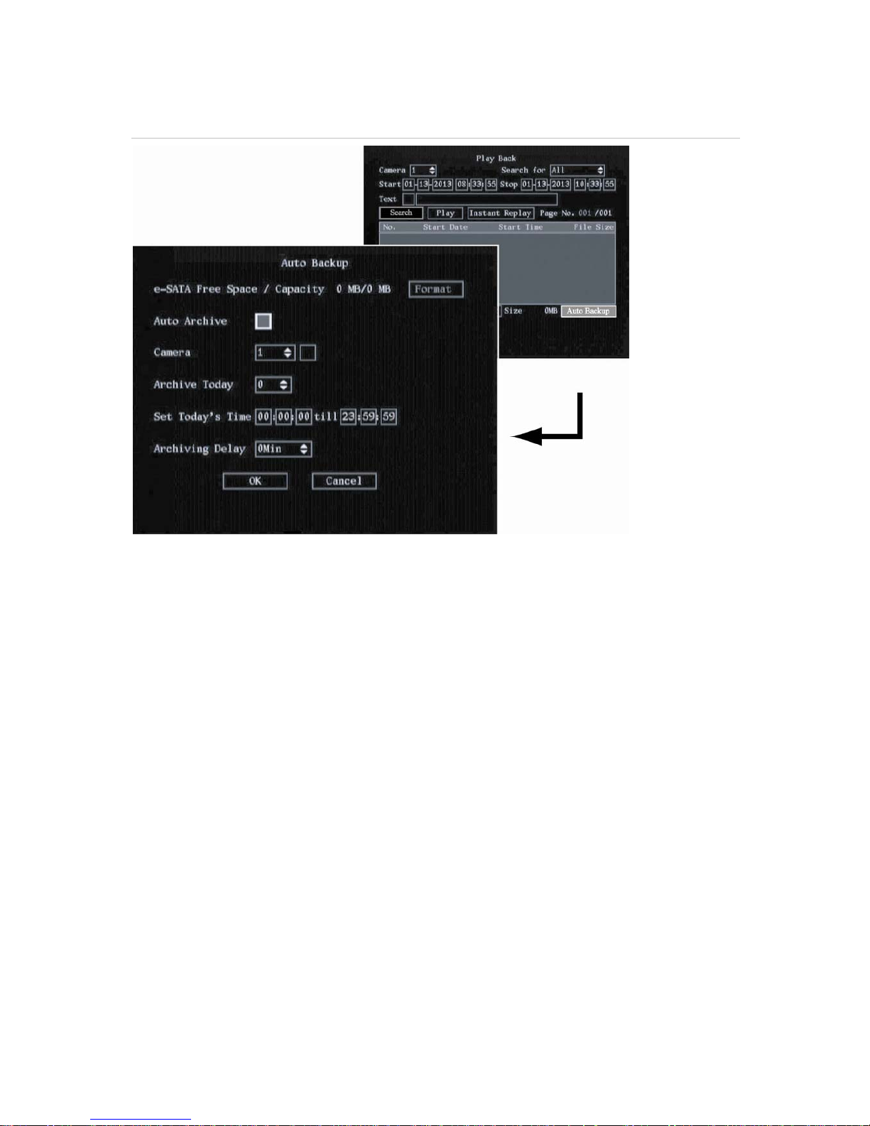
Figure 19: Auto Backup menu
4. Go to the e-Sata Free Space Format button and press Enter or left-click the mouse to format the
external drive.
Note: This action needs only to be done the first time you use the device.
5. Go to the Auto Archive check box and press Enter or left-click the mouse to enable Auto Archive.
6. Go to the Camera list box and select the camera whose recordings are to be archived and also
enable the check box beside the camera number box. Do this for each camera’s recordings to be
archived.
7. Go to the Archive Today list box to set the number of days back to be automatically archived. Up
to 6 days can be selected.
8. Go to the Set Today’s Time edit boxes and enter the period of time during the day to be archived.
Note: Time has a 24-hour format.
9. Go to the Archiving Delay list box and select the time after activating the DVSR xU for auto backup
to start.
10. Select OK to save your changes and return to live mode.
Page 27
DVSR xU User Manual 23
To archive all recorded files found in a search
1. Press the PLAY button, or right-click the mouse and select Search. Enter your user name and PIN,
if requested. The playback menu appears. See Figure 20.
Figure 20: The Playback menu
2. Search for the recorded files you want to copy. See To search for recorded video on
page 17. The
oldest file is listed first.
3. Press the A button to select all the video files listed. All files will be highlighted. To deselect all the
files, press A again.
4. Go to Media and select the desired medium on which to copy.
5. Go to Start and press Enter or left-click the mouse to write the files to the medium selected. A
message appears when copying is completed. Press OK.
6. Press ESC or right-click the mouse to quit playback mode and return to live mode.
To archive specific incidents in a recorded file
1.
Press the PLAY button, or right-click the mouse and select Search. Enter your user name and PIN,
if requested. The playback screen appears. See Figure 20 on page 23.
2.
Search for the recorded files you want to copy. See To search for recorded video on
page 17. The
oldest file is listed first.
3. If you want to save the copy to a medium that is different from that listed under Media, go to
Media and select the desired medium on which to copy.
4. Select the video file(s) in the search results list that you want to archive.
If using the front panel or remote control, press EDIT and select the file you want. Press Enter to
start playback.
If using the mouse, double click the file you want. Playback starts.
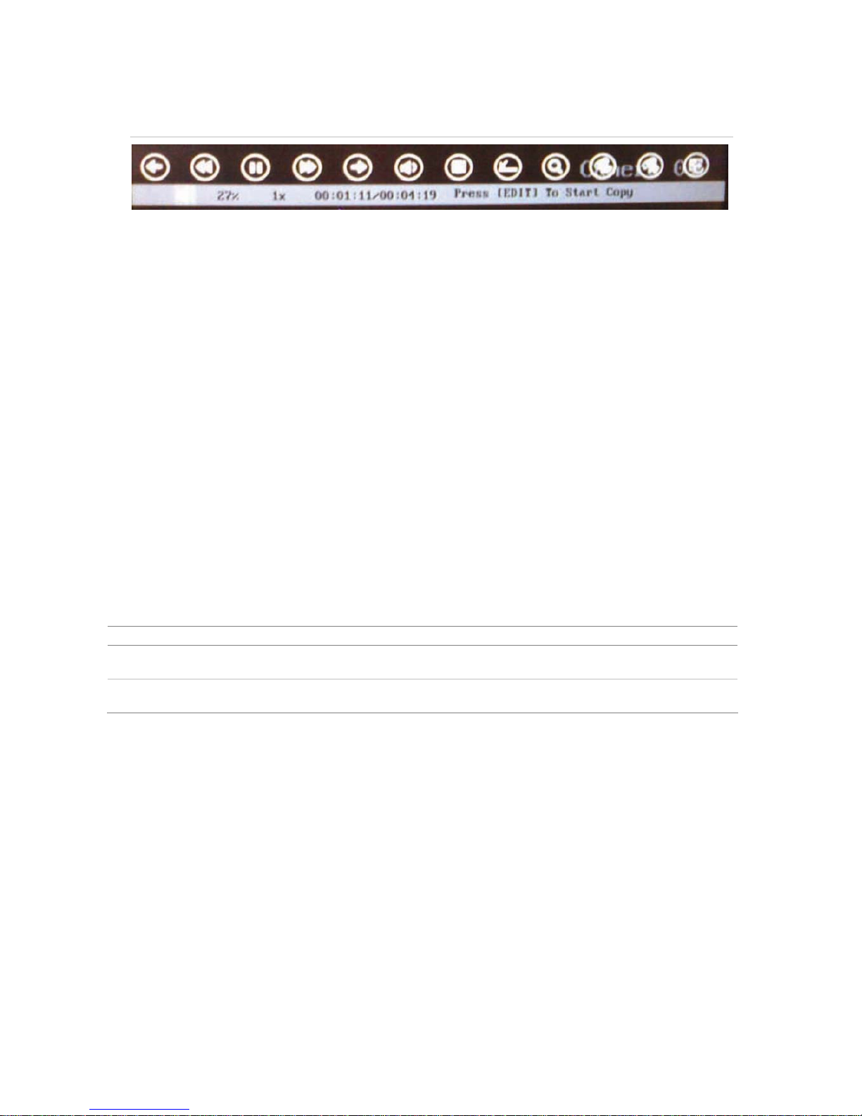
On the bottom of the playback screen you will see information on the playback progress of the
selected file. See Figure 21.
Page 28
24 DVSR xU User Manual
Figure 21: Playback tool bar
5. When you reach the part of the playback that you want to copy, press EDIT to start copying. A red
radio button appears in the right hand corner of the screen when copying is taking place.
Press EDIT again to stop copying. The red radio button disappears. You can copy several sections
of the same playback file.
6. Using the mouse, adjust the playback variables as required. See section Description of the
Play
back toolbar on page 19 for the description of the icons. Pla
yback can also be paused by
pressing Enter, and then pressing it again to restart it.
7. When finished copying this recording, press ESC or right-click the mouse to exit. A message
appears asking you to confirm that you want to copy the file. Select OK.
8. Press ESC or right-click the mouse to quit playback mode and return to live mode.
Controlling a PTZ camera
You can control the PTZ operation of the cameras. It is entered from live mode.
It can be controlled using buttons on front panel and IR remote control as well using the PTZ control
icons accessed with the mouse. See Figure 22 for the PTZ contr
ol icons onscreen and Table 4 for the
descriptions on how to control PTZ using the front panel, IR remote control and mouse.
To enter PTZ mode To exit PTZ mode
Front panel/remote
control
Press the PTZ button. Press the ESC or Enter buttons to return to
live mode.
Mouse Right-click the mouse and select the menu
option PTZ.
Right-click the mouse to return to live
mode.
Page 29
DVSR xU User Manual 25
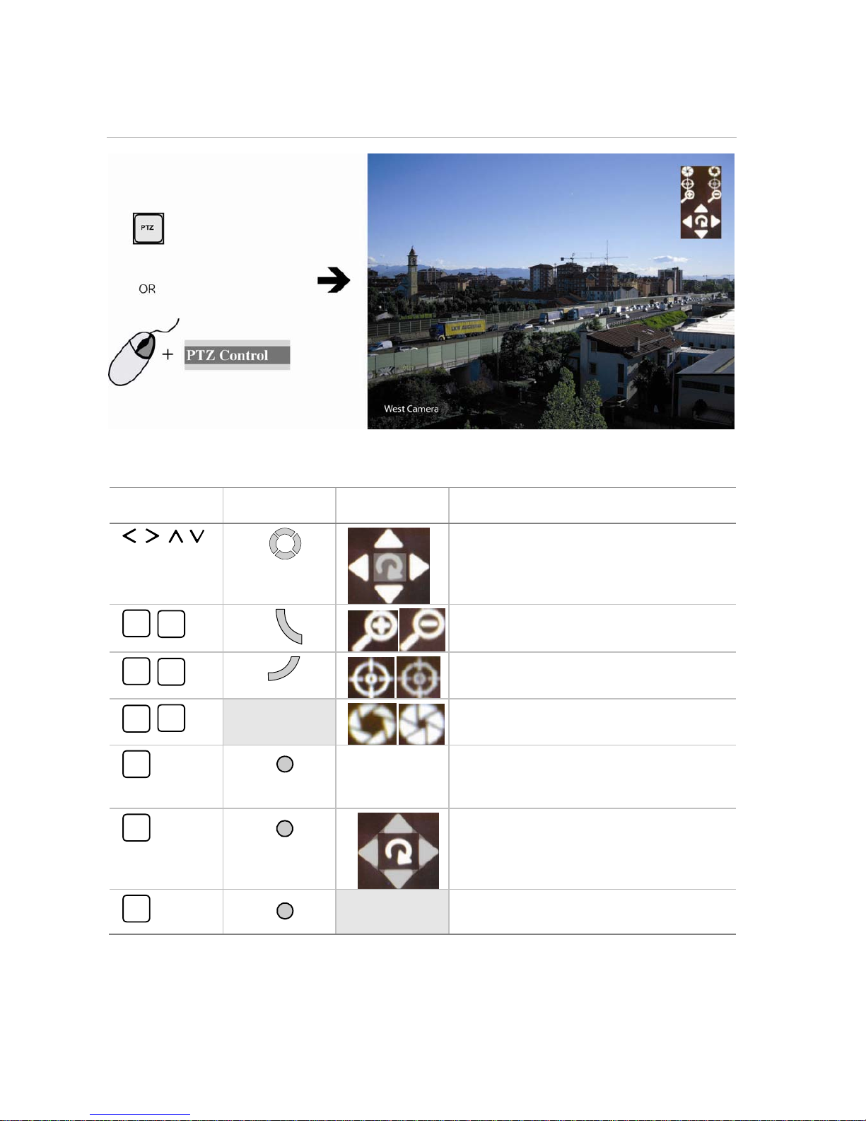
Figure 22: PTZ control
Table 4 Description of the PTZ control buttons
DVSR front panel IR remote control
Onscreen PTZ
control icons
Description
, , ,
Pan left/right and tilt up/down.
INFO
ZOOM+
VOIP
ZOOM-
Z
O
O
M
Zoom in (+) and out (-).
A
FOCUS+
PREV
FOCUS-
F
O
C
U
S
Focus in (+) and out (-).
EDIT
IRIS+
PTZ
IRIS-
Open (+) and close (-) the iris control.
REC
SHOT
SHOT
Right-click the
mouse and select
the Preset menu
command.
Call up preset.
PLAY
AUTO
PLAY
Call up autopan.
MENU
WIPER
MENU
Wiper control.
Page 30

26 DVSR xU User Manual
To call up a PTZ preset number
1. In PTZ mode, do one of the following:
Front panel Press the PTZ button to enter PTZ mode. Press the REC button and enter a
preprogrammed three-digit preset number. Preset starts immediately.
If you press a one or two-digit number (depending on DVSR xU model), you will
change the selected camera.
This function is only available when the mouse is not connected to the DVSR xU.
Remote control Press the PTZ button to enter PTZ mode. Press SHOT button and enter a
preprogrammed three-digit preset number. Presets start immediately.
If you press a one or two-digit number (depending on DVSR xU model), you will
change the selected camera.
This function is only available when the mouse is not connected to the DVSR xU.
Mouse Right-click the mouse and select PTZ control to enter PTZ mode. Right-click the
mouse again and select the menu option Preset. Select one of the preset
numbers listed.
Note: The PTZ preset number is preprogrammed. See section Configuring the PTZ settings on page 71 for
further information.
The DVSR xU will adjust to the settings of this preset number.
2. If you want to use a different preset PTZ number, repeat step 1 when in the PTZ mode. The DVSR
will re-adjust to that preset number.
3. To exit PTZ mode press ESC or Enter, or right-click the mouse and select Exit. You will return to live
mode and the camera will stay in its current position.
To start/stop autopan in PTZ mode
Autopan is th
e camera moving between two limits. The function depends on the camera used.
1. In PTZ mode, do one of the following:
Front panel Press the PLAY button to start the PTZ auto function. Press it again to stop.
Remote control Press AUTO button to start the PTZ auto function. Press AUTO again to stop.
Mouse Right-click the mouse and select PTZ control to enter PTZ mode. Click on the
autopan icon to start it.
Note: If the PTZ is in autopan mode and you exit PTZ mode, PTZ will continue in autopan mode. You must
re-enter PTZ mode to stop the autopan.
2. To exit PTZ mode press ESC or Enter, or right-click the mouse and select Exit. You will return to live
mode and the camera will stay in its current position.
Overview of the menu structure
The DVSR xU has an icon driven menu structure that allows you to configure the unit’s parameters.
Figure 23 shows the DVSR xU main menu screen. Each icon
symbolizes the content of the submenu.
The menu icon selected has a white action frame around it.
Many of the submenus are only available to privileged users, such as the system administrator.
You must be in live viewing mode to access the menu mode where you can setup or change the
DVSR xU settings in menu mode.
Page 31

DVSR xU User Manual 27
Figure 23: The DVSR xU main menu
Action frame
Table 5: Description of the eight menu icons
Menu icon Description
Display Configures the bus address, login PIN request, menu timeout, video standard, VGA, time and
date, and multiscreen.
See section Display on pa
ge 30.
Cameras Configures the camera titles, video adjustment, advanced camera settings, time and date
position, and motion detection.
See section Camera on page 36.
Recording Configures the recording mode, e-SATA, image resolution, recording rates, bits rates, and pre
and post recording settings.
See section Recording on page 49.
Network Configures the standard network settings, e-mail, and advanced network settings.
See section Network on
page 56.
Alarms Configures the alarm input type, alarm rules, alarm output type, PTZ linkage, notification
settings.
See section Alarm on p
age 63.
PTZ Configures the RS-485, PTZ protocols, and PTZ addresses. Comprehensive configuration of GE
domes, and basic setup of non-GE devices.
See section PTZ on page 69.
User Configures user rights.
See section User settings o
n page 76.
System Configures the RS-232. Manage firmware upgrade, and HHD. View log and system view.
Acknowledge alarms, reboot the DVR, and power off.
See section System on page 82.
To access the main menu
1. On the front panel of the DVSR or the IR remote control press the Menu button, or right-click the
mouse and select menu. Enter your name and PIN, if requested. The main menu appears.
Note: The factory default Administrator name is “Administrator“ and the PIN is “ 3477 “ .
2. Press the ESC button, or right-click the mouse, to quit the menu and return to the live mode.
Page 32

28 DVSR xU User Manual
To select a menu icon
1. In the main menu move the action frame onscreen to the desired menu icon.
2. Press Enter or left-click the mouse to enter the selected menu. The menu screen appears. Figure
2
4 shows the Camera menu.
Figure 24: The Camera menu
3. When you have finished changing all the menu options required, go to OK and press Enter or leftclick the mouse to save the changes. To abort all changes select Cancel and press Enter or ESC, or
left-click the mouse. You will return to the main menu screen.
Changing the menu settings
The DVSR xU is delivered with default settings that can be easily changed from the menus.
Caution: If there is a power failure, you will loose all user-modified settings. The systems will return to
the programmed settings.
Page 33

DVSR xU User Manual 29
To change settings in a menu
1. There are four ways to change the menu settings:
Table 6: Changing menu entries
Item Description
Check box
You can select either enabled (
) or disabled.
Press Enter or EDIT to toggle between them or left-click the mouse.
List box One of the listed options can be selected.
Front panel or remote control: Press Enter and then the arrow buttons to select an option. Press
Enter again to accept changes made in the list box.
Mouse: Position the mouse cursor on the list box arrows and left-click the mouse to scroll through
the options.
Edit box You can type characters in an entry.
Front panel/remote control:
Press EDIT to enter edit mode and then:
Press A to select the type of character required: number, upper case letter, lower
case letter, or symbols.
When you are in edit mode, the status bar on the bottom left of the screen shows
which type of characters can be entered into the menu option selected.
There are 24 different kinds of symbols to select. Press 0 to scroll between the four
pages of symbols.
Press arrow buttons to navigate the cursor in the edit box.
Press the EDIT button to delete the character in front of the cursor.
Press the Enter or ESC buttons to exit edit mode.
Mouse:
Left-click the mouse and a numeric or alphanumeric onscreen display appears.
Select the characters required. When complete, left-click the mouse on the edit
box to accept changes.
Setup button You can execute a function or enter into the next submenu.
A setup button is inactive until its parameter option is enabled. For example, in the Display menu
(see Figure 24) the menu options Zone and
Rules are grey as the Motion Detection is not enabled.
Exit the main menu and return to the live menu
Press the PREV or ESC button on the DVSR xU front panel or on the IR remote control, or right-click the
mouse, to exit the main menu and return to live mode.
Turning off the DVSR xU
There are two ways to turn off the unit:
Press and hold the POWER button on the front panel or on the IR remote control for at least five
seconds. A power off dialog screen prompts you to confirm your selection. Enter a user name and
PIN, if requested. If an incorrect user name or PIN is entered, the unit will return to live mode.
— or —
Turn off the power switch located on the back of the unit
Note: If you turn off the power by pressing the POWER button on the front panel, and the PIN enable option has
been enabled in the Display menu (page 32), you will need to enter your PIN before the DVSR xU will turn off.
Page 34

30 DVSR xU User Manual
5. Display settings
Use the Display menu to configure which information is displayed onscreen and how it should look.
The following options can be configured:
The language of the unit
The device ID
If a PIN is required
If the status bar appears onscreen
The menu timeout
The video output standard
The video scaling
The menu transparency
The VGA interface
The brightness of the screen
The system time and date
Daylight Saving Time (DST)
The Display menu icon
is located in the main menu. The following menu appears when you
select the Display icon:
Page 35

DVSR xU User Manual 31
Figure 25: The Display setup menu
Configuring the display settings
The following procedures show how to change the monitor display settings from the Display menu.
They can be changed in any order.
In the main menu, go to the Display menu icon and press Enter or left-click the mouse. The Display
menu appears.
To save changes made in the menu
1.
When you have made all the changes required in the Display menu, go to OK and press Enter or
left-click the mouse to save all the changes. To abort the changes, select Cancel and press Enter.
You will then return to the main menu.
Note: Selecting OK in submenus confirms but does not save the changes made. Changes are only saved
when OK is selected in the Display menu.
To select the language
1. In the Display menu go to Language and press Enter and use the arrow buttons, or left-click the
mouse, to select the required language. The language on screen changes immediately. The
default language is English.
Note: The last language used on the DVSR xU will be the unit’s language when the system is rebooted.
To change the DVSR xU’s bus ID
When you use the IR remote control to operate the DVSR xU, the DVSR xU must have a device ID. The
default device ID is “01“. If there is more than one DVSR used, each unit must have its own unique
device ID as otherwise the IR remote control will control all the DVSRs together.
Page 36

32 DVSR xU User Manual
Front panel or remote
control
Go to the Bus Address edit box and press EDIT. Using the number buttons, enter
the number of the device ID.
Mouse Go to the Bus Address edit box and left-click the mouse. Select the number from
the onscreen numeric display.
To setup the PIN requirement
A PIN is required by default to access the DVSR xU. See section To modify a user’s PIN on p
age 78 for
information on PINs.
1. In the Display menu go to the Log In PIN Required check box and press Enter or left-click the
mouse to enable or disable it ().
To setup the status bar
The status b
ar appears onscreen by default.
1. In the Display menu go to the Status Bar check box and press Enter or left-click the mouse to
enable or disable it ().
To setup the menu timeout
This is the time after which the screen saver appears.
1.
In the Display menu go to the Menu Timeout list box and press Enter or left-click the mouse. Select
the time.
To select the video standard
DVSR can
support PAL or NTSC video output. PAL is the default format.
1. In the Display menu go to the Video Standard list box and press Enter or left-click the mouse.
Select either NTSC or PAL video output format.
Note: If you are using default settings but the images on screen flicker, there is a NSTC/PAL mismatch.
Check the NTSC/PAL option selected in the Display menu.
To adjust the screen scaling
You can change the settings of the monitor display size to accommodate for differently sized
monitors.
1. In the Display menu go to the Video Scaler and press Enter or left-click the mouse to enable the
check box () When disabled, the video output display resolution is 704 x 576 PAL (or 704 x 480
NTSC). When activated the display resolution becomes 640 x 576 PAL (or 640 x 480 NTSC).
To change the menu transparency
You can modify the transparency
of menu items on screen relative to the background to make the
text on screen easier to read.
1. In the Display menu go to the Menu Transparency list box and press Enter or left-click the mouse.
Select the transparency level. The screen transparency changes as you scroll through the list of
options.
Page 37

DVSR xU User Manual 33
To setup the VGA interface
You can define the VGA resolution and refresh frequency.
1. In the Display menu go to the Menu Transparency list box and press Enter or left-click the mouse.
Select one of the options available:
1280*1024@60 Hz
1024*768@60 Hz (default)
800*600@60 Hz
To set the system time and date
You can setup the DVSR xU date and time as well as the Daylight Saving Time (DST). This is the date
and time that will appear on screen. You can setup when DST for the DVSR starts and stops in the
year. It is deactivated by default.
1. In the Display menu go to the Time & Date setup button and press Enter or left-click the mouse.
The Time & date submenu appears.
2. Go to the Date edit box and press Enter or left-click the mouse and use the number buttons to
enter the date. The default date format is dd-mm-yyyy.
3. Go to the Time edit box and use the number buttons to enter the time. The time format is 24-hour
format as hh-mm-ss.
4. Go to the Enable Daylight Savings check box and press Enter or left-click the mouse to enable.
Once enabled, the dates become active.
5. Select the month and day when Daylight Savings starts and stops.
8. Go to OK and press Enter or left-click the mouse to confirm the changes and return to the Display
menu.
To change live view layout
1.
In the Display menu go to Multi Screen setup button and press Enter or left-click the mouse. The
Multi Screen menu appears. See Figure 26.
Page 38

34 DVSR xU User Manual
Figure 26: Multi screen submenu
2. Go to the Monitor Output list box. Select between monitor output A or B. Monitor A is default.
3. Go to the Display list box. Select the desired multi screen mode from the drop-down list.
Table 7: Multi screen options available
Number of DVSR xU channels Multi screen options
4 1 screen
4 screen
6 to 8 1 screen
4 screens
6 screens
8 screens
16 1 screen
4 screens
6 screens
8 screens
9 screens
12 screens
16 screens
4. Go to the Dwell Time list box. Select the desired mode from the drop-down list.
Table 8: List of dwell time options
Options Description
off The live display will not automatically switch.
5S The live display will automatically switch after 5 seconds.
10S The live display will automatically switch after 10 seconds.
20S The live display will automatically switch after 20 seconds.
30S The live display will automatically switch after 30 seconds.
Page 39

DVSR xU User Manual 35
For example: If a 16-channel DVSR xU has the 4-screen live mode and the 20-second switch time
mode selected, the DVSR xU will cycle four camera displays every 20 seconds.
5. Go to the Audio check box and press EDIT or left-click the mouse to enable ().
6. Go to Alarm Aux Out to select which monitor should work as an alarm spot monitor. If there is an
alarm, the video will pop up on this monitor.
7. Go to the Alarm Dwell Time edit box and select the time delay required: Off, 3, 4, 5, or 10 seconds.
This is the time delay before the alarm video appears onscreen. If there is more than one alarm,
there is also the delay switching between the alarm videos.
8. Go to Display Layout. Select in which order the cameras will be displayed by going to the first
square and press the number button(s) that correspond to the number of the camera you want
displayed first. Continue for each camera. The order they will be previewed is displayed in the bar
underneath.
Note: It is recommended that you first select the layout order and then the live mode.
9. When complete, go to OK and press Enter or left-click the mouse to accept all the changes and
return to the Display menu.
Page 40

36 DVSR xU User Manual
6. Camera settings
Use the Camera menu to configure the cameras. The following options can be configured:
The name of each camera
The position of the camera name on screen
The camera brightness, contrast, saturation and hue
The display properties of each camera (OSD)
The area on screen to be masked
When to view a tamper alarm
The video loss alarm
The motion detection alarm
The Camera icon
is located in the main menu. The following menu appeas when you select the
Camera icon:
Figure 27: The Camera menu
Page 41

DVSR xU User Manual 37
Configuring camera settings
The following procedures show how to change camera settings from the Camera menu. They can be
changed in any order.
In the main menu, go to the Camera menu icon and press Enter or left-click the mouse. The Camera
menu appears.
All changes made to the Camera menu apply to the selected camera. The camera settings of one
camera can easily be copied to another camera.
To save changes made in the menu
1.
When you have made all the changes required in the Camera menu, go to OK and press Enter or
left-click the mouse to save all the changes. To abort the changes, select Cancel and press Enter.
You will then return to the main menu.
Note: Selecting OK in submenus confirms but does not save the changes made. Changes are only saved
when OK is selected in the Camera menu.
To setup the camera title
Each camera can be given a title, which must be unique. If you do not give a camera a title, it is
automatically pre-numbered.
1. In the Camera menu go to the Camera list box and press Enter or left-click the mouse. Select the
number of the camera you want to name.
2. Go to the Title setup box and press the EDIT button or left-click the mouse to enter into edit mode.
3. Enter the camera title. You can use numbers, uppercase and lowercase letters, and some special
characters such as commas and colons. The camera title can have up to 32 alphanumeric
characters.
Front panel and
remote control
Press button A and then an alphanumeric button to change the
character input type. Press the A button 1 to 4 times to scroll through the
type of characters available for an alphanumeric button.
Mouse An onscreen display appears showing the alphanumeric keys. Click Shift
to select which type of character you want (for example, uppercase or a
special character such as comma and colon).
4. Press Enter or left-click the mouse to confirm your change.
To position the camera title on screen
You can position the camera t
itle anywhere on screen.
1. In the Camera menu enable the Title Position check box () if you want the camera title to appear
on screen. When enabled, the Position setup button alongside it becomes active.
2. Go to the Position setup button and press the EDIT button or left-click the mouse to enter into edit
mode. A grid appears onscreen with the camera title in the bottom right corner.
3. Using the arrow buttons, move the camera title around the screen. When you are satisfied with
the position, press Enter or left-click the mouse to confirm and return to the Camera menu.
Page 42

38 DVSR xU User Manual
To adjust the image quality of the camera video
Different cameras and backgrounds may need to have the screen image modified in order to obtain
the best video image. Use this menu to configure the video image. You can setup each camera
separately or copy the video parameters of one camera to another camera.
1. In the Camera menu select the camera you want to adjust. Go to the Adjust Video setup button
and press Enter or left-click the mouse. The Adjust Video menu appears.
2. Go to the Brightness setup button and press Enter or left-click the mouse. A scroll bar appears at
the bottom of the screen. See Figure 28.
Figure 28: The Brightness option in the camera Adjust Video submenu
3. Use the arrow buttons to adjust the brightness level. The video camera changes at the same time.
4. When you are satisfied with the real time video of the camera, press Enter or left-click the mouse.
5. Repeat steps 2 to 4 for the Contrast settings of this camera.
6. Repeat steps 2 to 5 for other cameras.
7. When you are completed, select OK and return to the Camera menu.
Page 43

DVSR xU User Manual 39
To setup a camera’s displayed time and date
1. In the Camera menu select the camera you want to adjust.
2. Go to the Time & Date list box and press Enter or left-click the mouse to select the display mode
required. See Figure 29 and Table 9 for the list of options.
Figure 29: The Time & Date display in the Camera menu
Table 9: List of display mode options for time and date
Solid The text contrast automatically adjusts relative to the background.
Transparent The screen image appears through the text.
Not Displayed Nothing is displayed (Default).
3. Press Enter or left-click the mouse to confirm the entry.
4. Go to the Position setup button and press Enter or left-click the mouse. A grey screen with the
date/time bar in white appears.
5. Press EDIT if using the front panel or remote control, or right-click the mouse and select Format,
to change the information displayed: Date, day of the week and time, or Date and time.
Page 44

40 DVSR xU User Manual
Figure 30: Positioning date/time bar
6. Using the arrow buttons move the date/time bar around the screen. When you are satisfied with
the position press Enter, or right-click the mouse and select OK, to return to the Camera menu.
To setup the DVSR xU to respond to a motion detection alarm
The DVSR
can be setup to trigger an alarm if a camera detects motion. You can select the level of
sensitivity to motion, where on screen the motion can be detected, and specify which cameras can
record the motion when a motion alarm is detected.
1. To set the motion detection sensitivity level
In the Camera menu go to Motion Detection list box and select the desired motion detection
sensitivity level required.
There are seven levels to choose from: 0 (lowest) to 6 (highest) as well as “Off”. If “Off” is selected,
the unit will not respond to any motion detection. If 0 to 6 is selected, motion detection Zone and
Rules setup buttons become active. Press Enter or left-click the mouse to confirm the change.
Page 45

DVSR xU User Manual 41
2. To select the motion detection zone(s)
a. Go to the Zone setup button and press EDIT or left-click the mouse. The Motion Zone setup
screen appears. See Figure 31.
Figure 31: The Motion Zone setup screen
There is a solid white pane onscreen. The motion zone setup steps are the same as those for
mask zone setup (see page 44).
Use the following buttons to setup the motion zones:
Button Action
, , ,
Move the white pane to any position
EDIT Toggle between the white and grey panes
Increase the size of the transparent zone from the right
Decrease the size of the transparent zone from the left
Increase the size of the transparent zone downwards
Decrease the size of the transparent zone from above
PTZ Select the whole screen as a motion zone
A Clear all motion zones
Enter Save changes and return to the Camera menu
ESC Cancel setup and return to the Camera menu
b. Move the white square to the zone on screen that you want to mark as a motion detection
zone. Press EDIT or left-click the mouse. The square becomes transparent. This shows the
zone that will detect motion.
c. Use the arrow buttons or drag the square with the mouse cursor to extend the transparent
square. When you have finished marking out the transparent zone to be masked, press EDIT
to exit and return to the solid white square to continue masking.
d. Repeat steps b and c for each zone on screen where you want to detect motion. An example
of motion detection zones on screen is shown in Figure 32.
Page 46

42 DVSR xU User Manual
Figure 32: Example of motion detection zones
e. To clear part of a motion detection zone, move the solid white square to the motion detection
zone that you want to delete. Press EDIT.
The white pane becomes transparent. Use the arrow keys to increase or decrease the size of
the black zone. When finished, press EDIT to clear this transparent zone.
To clear all motion detection zones, press the A button.
f. Press Enter, or right-click the mouse and select OK, to confirm and return to the Camera
menu.
3. To setup the response rules to a motion alarm
a. Go to the Rules setup button and press EDIT or left-click the mouse. The Rules menu appears.
See Figure 33.
Page 47

DVSR xU User Manual 43
Figure 33: The motion alarm Rules submenu
b. Go to the Record Camera check boxes and select the cameras from which you want to be
able to record a motion alarm. Press Enter or left-click the mouse to enable the option. Press
or click again to disable.
Note: For the cameras to be able to record a motion alarm, they must first be setup for motion
recording. This is done in the Recording menu. See page 53 for more
information.
c. Go to Alarm Schedule and select when you want the DVSR xU to respond to a motion alarm.
You can select up to seven days in a week and up to four time periods for each a day.
Note: The four daily time periods cannot overlap.
d. Go to the notification options and press Enter or left-click the mouse to enable () or disable
how you want the DVSR xU to respond to a motion alarm during live mode.
Table 10: Notification options on how to respond to a camera tamper alarm
Notification option Reponse
Alarm Out Alarm Out is activated. Up to four alarm outputs can be enabled.
Buzzer An audible alarm sounds
TCP Alarm information is sent to the remote IP (see section Network on page 60
for more information)
Full Screen The alarm channel will be displayed on screen
Email Alarm information is sent to an e-mail address (see section Network on
page 58 for more information)
The DVSR xU returns to live mode when there is no longer a motion alarm.
e. If you want to copy the periods from one camera to another, go to the Copy to list box and
select which day you want to copy to and then select Copy.
4. Select OK to confirm the changes and to return to the Camera menu.
Page 48

44 DVSR xU User Manual
To setup a privacy mask
You can mask a sensitive area on screen so that it remains hidden from view. An example would be
when the view of a camera overlooks onto residential premises. The area hidden by the privacy mask
will not be viewed live nor recorded, but will appear as a blank area on screen.
1. In the Camera menu go to Advanced settings setup box and press Enter or left-click the mouse.
The Advanced Settings submenu appears. See Figure 34.
Figure 34: Advanced settings submenu
2. Go to the Privacy Masking check box and press Enter or left-click the mouse to enable (). The
Zone option is activated. Privacy masking is disabled by default.
Note: No masked zone appears onscreen when Privacy Mask is disabled.
3. Go to the Zone button and press Enter or left-click the mouse.
The matrix screen appears. For PAL there are 22 x 18 panes in the matrix. In the top left-hand
corner of the matrix there is a white pane. See Figure 35.
Figure 35: The mask zone matrix
Page 49

DVSR xU User Manual 45
4. Use the arrow buttons to move the white pane to the zone on screen that you want to mask.
Press EDIT or left-click the mouse to select the first square. The pane turns transparent. The
transparent pane indicates the zone that will be masked.
5. Use the arrow buttons, or drag the mouse cursor, to extend the transparent pane. When you have
finished marking out the black zone to be masked, press Enter or left-click the mousse. The
square pane becomes white again. Continue masking, or press ESC to cancel.
There can be up to four masked zones in a screen. The maximum size of a masked zone is 8 x 8
panes. The minimum size is one pane. See Error! Reference source not found..
6. Press Enter to return to the advanced settings submenu.
Note: The changes have not yet been saved. Changes are only saved when OK is selected in the Camera
menu screen.
7. Repeat steps 1 to 6 for the other cameras that require masking.
8. In the Advanced Settings submenu press OK to return to the Camera menu.
To clear all masked zones
In the mark zone setup screen press the A button to clear all masked zones. It is not possible to
clear a specific masked zone.
To setup the viewing of a camera tamper alarm
You can s
etup the system to alert you when someone has deliberately blocked a camera view, such
as by spraying paint on the lens (also known as anti-masking). You can set it up so that a specific part
of the screen can detect a tamper and thereby trigger an alarm. You can also setup how the system
will alert you to the tamper alarm. You can only setup one anti-masking area on screen.
1. In the Camera menu go to Advanced settings setup button and press Enter or left-click the mouse.
The Advanced Settings submenu appears. See Figure 34 on page 44.
2. To set
the detection sensitivity level to a camera tamper alarm
Go to the Camera Tampering list box. Select the sensitivity level required. The options are:
Off
Low
Normal (default)
High
When Low, Normal, or High are selected, the Zone and Rules setup boxes become active.
The Zone submenu allows you to select in which part of the screen a tamper can be detected and
trigger an alarm.
The Rules submenu allows you to setup how to handle warning notifications, such as alarm
operational issues.
Page 50

46 DVSR xU User Manual
3. To set the zone on screen that can trigger a camera tamper alarm
a. In the Advanced Settings submenu go to the Zone setup button. Press Enter or left-click the
mouse to access the matrix screen.
b. The setup is the same as for masking a zone. See the section on setting up a privacy mask on
page 44 for further instructions.
Note: Only one zone can be masked to trigger a camera tamper alarm.
c. When you have finished masking the tamper zone press Enter, or right-click the mouse and
select OK, to confirm your changes and return to the Camera menu.
4. To setup the tamper alarm response
a. In the Advanced Settings submenu go to the Camera Tampering Rules setup button. Press
Enter or left-click the mouse to access the Rules submenu. See Figure 36.
Figure 36: The camera tampering Rules submenu
b. Go to the Alarm Schedule list box. Select the day of the week for which you want to set the
response time schedule.
c. Go to Period 1 and enter the time period for the response. You can set up to four time periods
for each day of the week. You must reboot the DVSR xU to make the time periods operational.
Note: The daily time periods cannot overlap.
d. Go to the notification options and press Enter or left-click the mouse to enable () or disable
how you want the DVSR xU to respond to a camera tamper alarm. See Table 11.
Page 51

DVSR xU User Manual 47
Table 11: Notification options on how to respond to a camera tamper alarm
Notification option Reponse
Alarm Out Alarm Out is activated. Up to four alarm outputs can be enabled.
Buzzer An audible alarm sounds
TCP Alarm information is sent to the remote IP (see section Network on page 60
for more information)
Full Screen The alarm channel will be displayed on screen
Email Alarm information is sent to an e-mail address (see section Network on
page 58 for more information)
e. When you have finished modifying all the menu items required, select OK to confirm changes
and return to the Camera menu.
5. Repeat steps 2 to 4 for each camera and then return to the Camera menu.
To setup a video loss alarm
The video
image can be lost if a video cable or camera develops a fault. The unit can be setup so that
an alarm is triggered when a video loss fault occurs. However, the video loss alarm is only triggered if
it occurs during a programmed time schedule
1. In the Camera menu go to the Camera list box. Select the camera whose options you want to
modify.
2. Go to the Advanced Settings submenu and enable () the Video loss check box. The Rules setup
button is activated.
3. Go to the Rules setup button and press Enter or left-click the mouse. The video loss rules submenu
appears. See Figure 37.
Figure 37: The video loss rules submenu
Page 52

48 DVSR xU User Manual
4. Go to the Alarm Schedule and select the day of the week for which you want to set the response
time schedule. Go to Period 1 and enter the time period for the response. You can set up to four
time periods for each day of the week. Time is entered in the 24-hour format.
Note: The four daily time periods cannotoverlap.
5. Go to the notification options and press Enter or left-click the mouse to enable () or disable how
you want the DVSR xU to respond to a video loss tamper alarm. See Table 12.
Table 12: Notification options on how to respond to a video loss tamper alarm
Full Screen On Alarm channel will be displayed full
Buzzer An audible alarm sounds
TCP Alarm information is sent to the remote IP (see Network section.)
Email Alarm information is sent to an Email address (see Network section.)
Alarm Out When enabled, the Alarm Out is activated. Up to four alarm outputs can be
enabled.
6. Select OK to confirm changes and return to the Camera menu.
To copy a camera’s settings to another camera
1.
In the Camera menu go to the Camera list box and select the camera whose options you want to
copy.
2. Go to Copy to Camera and select the camera to which you want to copy the settings.
3. Go to Copy and press Enter or left-click the mouse. All settings will be copied to the selected
camera.
Note: Motion alarm zones cannot be copied.
Page 53

DVSR xU User Manual 49
7. Recording settings
Use the Recording menu to setup how the DVSR xU records information. The following options can be
configured:
Handling information when the HDD is full
eSATA record or backup
Auto deletion
Audio and/or video recorded
Bit rate
Frame rate
Camera resolution
Recording schedule of a camera
Pre and post recording times for alarm recordings
Configuring the recording settings
The Recording icon is located in the main menu. The following screen appears when you select
the Recording icon:
Page 54

50 DVSR xU User Manual
Figure 38: The Recording menu
The following procedure shows how to change the recording settings of a selected camera in the
Recording menu. They can be changed in any order.
In the main menu, go to the Recording icon and press Enter or left-click the mouse. The Recording
menu appears.
To save changes made in the menu
1.
When you have made all the changes required in the Recording menu, go to OK and press Enter
or left-click the mouse to save all the changes. To abort the changes, select Cancel and press
Enter. You will then return to the main menu.
Note: Selecting OK in submenus confirms but does not save the changes made. Changes are only saved
when OK is selected in the Recording menu.
To setup how the DVSR xU will respond to full HDDs
You can select how the DVSR xU responds when its HDDs become full and there is no longer sufficient
space to save new data.
1. In the Recording menu go to the Record Mode list box and select one of the two options:
Table 13: Options on how to respond to full HDDs
Option Description
Continuous When all the HDDs in the DVSR xU are full, the DVSR will overwrite the earliest written recorded
files and continue recording.
No Overwrite When all the HDDs in the DVSR xU are full, the DVSR will handle the event as a “Hard Disk Full”
condition and respond according to how this condition has been programmed under the
Notification menu. For more information, see page 56.
Page 55

DVSR xU User Manual 51
To select if the e-SATA port should record or backup
You can use an external storage device, such as an e-SATA HDD, as a backup for video or add its
recording capacity to that of the DVSR xU itself. If you change this option, you must reboot the
DVSR xU to implement the change.
1. In the Recording menu go to the e-SATA edit box and select one of the two options:
Table 14: Options on eSATA
Option Description
Record Extend the recording capacity of the DVSR xU. If the e-SATA storage device is part of the
total storage capacity then only the USB storage device can be used as backup.
Backup Backup data onto an e-SATA backup device, such as a USB storage device, DVSR DVR, or
DVSR backup device. For further information see also section Archiving recorded files on
page 19.
Cauti
on: If the external storage is part of the total internal capacity (the Record option has
been selected), the external device is no longer accessible for exporting video.
To setup the Auto Delete Mode (ADM)
You can select the number of days that recordings from a specific camera are saved before being
automatically deleted. The default value is 30 days.
1. In the Recording menu go to the Camera list box and select the camera whose settings you want
to modify.
2. Go to the ADM edit box and enter the number of days after which auto delete occurs.
3. Press Enter or left-click the mouse to confirm the entry.
To change the recording parameters of a camera
Use this
submenu to select how the DVSR xU responds to normal and alarm events. The record type,
resolution, bit rate, and image quality can all be made to be higher for when an alarm event is
recorded. See Table 15 for the limitations in dual streaming.
Table 15: Stream limitations
Maximum resolution supported Note
Main stream 2 CIF 12 fps
4 CIF 8 fps
These can be specified from the DVSR xU unit.
Sub stream CIF Real time
QCIF Real time
These cannot be specified from the DVSR xU unit. They
can only be specified from the browser.
1. In the Recording menu go to the Camera list box and select the camera whose settings you want
to modify.
Page 56

52 DVSR xU User Manual
2. Go to the Record Para setup box and press Enter or left-click the mouse. The Recording submenu
appears. See Figure 39.
Figure 39: The Recording submenu
3. To setup normal and alarm recordings
You can select the recorded image parameters for both normal and alarm events. However,
Enable Event must enabled for alarm events to be recorded differently from normal events. If this
option is not enabled then it is not possible to change any image parameters when Event is
selected as a setting—all event parameters will be identical to those of normal events.
a. If you want the recorded image parameters for alarm events to be different from those of
normal events, go to the Enable Event check box and press Enter or left-click the mouse to
enabled the check box (). Press or click again to disable.
b. Select which event type you want to set:
Option Description
Normal Records both scheduled and manual.
Event Records all alarms.
4. To select audio and/or video recording
You can select whether the recording is video only (default), or audio and video. If you change this
option, you must reboot the DVSR xU to implement the change.
Page 57

DVSR xU User Manual 53
Go to the Stream Type list box and select one of the two options:
Option Description
Audio&Video Records both audio and video.
Video Records video only.
5. To change the camera resolution
You can select one of four video resolutions. A high image resolution requires that a high bit rate
must also be selected. QCIF is the lowest resolution value and 4CIF the highest. If you change this
option, you must reboot the DVSR to implement the change.
Go to the Resolution list box and select one of the options listed: QCIF, CIF (default), 2CIF, and 4CIF.
6. To select the frame rate
You can select between several different frame rates. A low bit rate can be selected when the
frame rate is low.
Go to the Record Rate/fps list box. Use the arrow buttons to select one of the options listed: Full
(PAL is 25 FPS and NTSC is 30FPS), 20, 16, 12, 10, 8, 6 (default), 4, 2, 1, 1/2, 1/4, 1/8, 1/16.
7. To select the maximum bit rate
See Table 16 for the recommended bit rate ranges by resolution option. The actual
maximum bit
rate must be calculated from your camera, background, and image quality requirements.
Table 16: Bit rate by resolution
Resolution Default bit rate Recording speed
4CIF 896 Kbps 8 fps
2CIF 896 Kbps 12 fps
CIF 1.0 Mbps Real time
QCIF 256 Kbps Real time
Go to the Max Bit Rate list box and select one of the options listed (bps):
32K, 48K, 64K, 80K, 96K, 128K, 160K, 192K, 224K, 256K, 320K (default), 384K, 448K, 512K, 640K,
768K, 896K, 1M, 1.25M, 1.5M, 1.75M, 2M, and “User defined“.
8. Select OK to confirm changes and return to the Recording menu. Select OK in the Recording menu
to save changes and return to the main menu.
To setup a camera’s recording schedule
You can setup a recordin
g schedule for selected camera(s). You need to reboot the DVSR after
changing this option
1. In the Recording menu go to the Camera list box and select the camera for which you want to do
a recording schedule.
2. Go to the Record check box and press Enter or left-click the mouse to enable () scheduled
recording. When the check box is enabled, the Record schedule setup button is activated.
3. Select the Record schedule setup button and press Enter or left-click the mouse. The Schedule
submenu appears. See Figure 40.
Page 58

54 DVSR xU User Manual
Figure 40: The camera recording schedule submenu
4. In the Day list box select the day of the week for which you want to set the recording schedule.
5. For period 1 select the start and end recording times for that day. Select Record Type and set the
type of recording (All time, Motion, Alarm, Motion or Alarm, Motion and Alarm, or Command).
6. Repeat steps 3 and 4 for the other required time periods.
Note: The four daily time periods cannot overlap.
7. Select the schedules for the other days of the week for this camera as required.
8. When completed, select OK to confirm changes and return to the Recording menu.
To set the pre recording time for motion det
ection alarm and external alarm recordings
Before you set the prerecording time you must first enable the DVSR xU to respond to a motion
detection alarm (see section To setup the DVSR xU to respond to a motion detection alarm on
page 40)
and/or an external alarm (see section To setup an external alarm output on
page 67).
The DVSR xU is recording all the time at a defined rate. The prerecording time is the time before a
motion or external alarm is triggered and which is included in the alarm data. It is related to the bit
rate. The lower the selected bit rate, the longer the prerecording time can be.
1. In the Recording menu go to the Pre Event Time list box and select one of the time options listed
(Disabled, 30S, 25S, 20S, 15S, 10S, and 5S).
To set the post recording time for motion detection alarm and external alarm recordings
Before you
set the prerecording time you must first enable the DVSR xU to respond to a motion
detection alarm (see section To setup the DVSR xU to respond to a motion detection alarm on
page 40)
and/or an external alarm (see section To setup an external alarm output on
page 67).
The post recording time is the time after a motion or external alarm is triggered that is included in the
alarm data.
Page 59

DVSR xU User Manual 55
1. In the Recording menu go to the Post Event Time list box and select one of the options listed
(Disabled, 10 min, and 5 min).
To copy the camera settings
1.
Go to the Copy to Camera list box and select one of the cameras listed.
2. Go to Copy press Enter or left-click the mouse.
3. DVSR xU will ask you if you want to copy the current camera settings to another Camera. Select
OK or Cancel.
Page 60

56 DVSR xU User Manual
8. Network settings
Use the Networking menu to setup the network settings of the DVSR xU. The following options can be
configured:
IP address and settings
Subnet mask
Gateway IP
DNS address
Network communication port
HTTP port
E-mail notification
PPPoE
DDNS
The Network icon
is located in the main menu. The following screen appears when you select
the Network icon:
Figure 41: The Network menu
Page 61

DVSR xU User Manual 57
Configuring the network settings
The following procedure shows how to change the recording settings of a selected camera in the
Recording menu. They can be changed in any order.
In the main menu go to the Network menu icon and press Enter or left-click the mouse. The Network
menu appears.
Caution: The DVSR xU will automatically reboot when any network parameter is changed and saved.
To save changes made in the menu
1. When you have made all the changes required in the Network menu, go to OK and press Enter or
left-click the mouse to save all the changes. To abort the changes, select Cancel and press Enter.
You will then return to the main menu.
Note: Selecting OK in submenus confirms but does not save the changes made. Changes are only saved
when OK is selected in the Network menu.
To change the IP address value
1. In the Network menu go to the IP edit box and press EDIT or left-click the mouse. Using the
numeric buttons enter the IP address. Press Enter or left-click to the mouse to accept the
changes.
The DVSR xU will use a DHCP server to find a dynamic IP address when IP 0.0.0.0 is used. If the
DVSR xU uses a PPPoE function, the unit dials-up the internet and displays the dynamic Internet IP
address.
To change the SubNet mask value
1.
In the Network menu go to the Subnet edit box and press EDIT or left-click the mouse. Using the
numeric buttons enter the sub net mask number. Press Enter or left-click the mouse to accept the
changes.
To change the Gateway IP value
1.
In the Network menu go to the Gateway edit box and press EDIT or left-click the mouse. Using the
number buttons enter the gateway IP number to communicate with different network segments.
Press Enter or left-click the mouse to accept the changes..
To change the DNS address value
If DVSR
uses a PPPoE function, the DVSR xU can get a dynamic IP address. If you set DNS IP with a
fixed Internet IP, DVSR xU will send information such as its name, serial number, and current IP to that
fixed IP address. When seeking the DVSR xU name of a unit, the DVSR xU will automatically provide
you with its dynamic IP address.
Page 62

58 DVSR xU User Manual
1. In the Network menu go to the DNS edit box and press EDIT or left-click the mouse. Using the
numeric buttons enter the DNS number. Press Enter or left-click the mouse to accept the changes.
To change the Network communication port value
1.
In the Network menu go and go to the Com Port edit box and press EDIT or left-click the mouse.
Using the numeric buttons enter the address and press Enter. The number must be greater than
2000.
To change the HTTP port value
1.
In the Network menu go to the HTTP Port edit box and press EDIT or left-click the mouse. Using
the numeric buttons enter the IE browser port value. Press Enter or left-click the mouse to accept
the changes. The default value is 80.
Note: If you change the http port from the default value 80 then you must also enter the port value in the IE
Browser address. For example, if the http port is 81 and IP is 192.168.222.12 then in the browser enter
http://192.168.222.12:81
To setup E-mail notification
1. In the Network menu go to the E-mail setup box and press Enter or left-click the mouse. The E-
mail submenu appears. See Figure 42.
Figure 42: E-mail submenu
2. If your E-mail server requires a user name and PIN when you want to send an E-mail, select
Authentication and press EDIT or left-click the mouse to enable the check box (). The User and
Password setup boxes are activated.
3. Go to the User edit box and press EDIT or left-click the mouse. Enter the e-mail account user
name. If using the front panel or remote control, press Enter to accept the changes.
Page 63

DVSR xU User Manual 59
4. Go to the Password edit box and press EDIT or left-click the mouse. Enter the e-mail account
password. If using the front panel or remote control, press Enter to accept the changes.
5. Go to the Sender Name edit box and press EDIT or left-click the mouse. Enter the name of the
person sending the e-mail. If using the front panel or remote control, press Enter to accept the
changes.
6. Go to the Sender Address edit box and press EDIT or left-click the mouse. Enter the e-mail address
of the sender. If using the front panel or remote control, press Enter to accept the changes.
7. Go to the Email Server edit box and press EDIT or left-click the mouse. Enter the SMTP server
address. If using the front panel or remote control, press Enter to accept the changes.
8. You can send e-mail notifications to up to two addresses. In the Mail Receiver No. list box select
whether Receiver Number 1 or 2 will receive the notification. Depending on which is selected, the
Name and Address numbers will automatically change.
9. Go to the Name edit box and press EDIT or left-click the mouse Enter the name of the receiver
that should appear in Email as the receiver. If using the front panel or remote control, press Enter
to accept the changes.
10. Go to the Address edit box and press EDIT or left-click the mouse. Enter the e-mail address of the
receiver. If using the front panel or remote control, press Enter to accept the changes.
11. Repeat steps 8 to 10 if there is a second receiver.
12. You can send a JPEG attachment with the e-mail. Go to Attachment and press Enter or left-click
the mouse to enable () the check box. The JPEG Capture Interval list box becomes activated.
13. The unit can send five jpeg images of a recording with the e-mail. You need to define the capture
interval in seconds between each jpeg. Select the capture interval from the list.
Note: Check with your ISP or IT department for details on mail server and mail server login.
14. Select OK to return to the Network menu.
To setup the Advanced IP settings
1.
In the Network menu go to the Advanced Settings setup box and press Enter or left-click the
mouse. The Advanced Settings submenu appears. See Figure 43.
The MAC Add
ress edit box shows the MAC address of the DVSR xU unit.
Page 64

60 DVSR xU User Manual
Figure 43: Advanced settings submenu
2. Go to the NIC Type list box and select one of the five options listed.
3. Go to the Input Format list box and select either IP or Domain Name.
If you chose the option IP, FTP IP appears below. For the option Domain Name, Domain Server
appears instead.
4. Depending on which entry is shown, use the numeric buttons to enter the IP address of the FTP IP,
or the domain server of the Domain Name.
Note: Use the FTP IP if the PPPoE function is being used, and the DVSR xU gets a dynamic IP address from
the ISP. If you set the FTP IP you will get one fixed Internet IP, DVSR xU will send information such as its
name, serial number, and current IP to that fixed IP address. This is calledthe Fixed Transfer Protocol IP (FTP
IP). The IP server with that fixed Internet IP can receive DVR information and be used to resolve DVR
dynamic IP. Contact your local supplier to obtain the IP server software.
5. Go to the Multicast IP edit box and press EDIT or left-click the mouse. Using the numeric buttons
enter a D-class IP address between 224.0.0.0 - 239.255.255.255, and press Enter. This function is
optional as not all systems use it.
Note: Some routers or network switchers do not allow the multicast function. Multicast is not supported
over the internet by ISP providers.
6. Go to the Remote Host IP edit box and press EDIT or left-click the mouse. Using the numeric
buttons enter the remote host IP address. If using the front panel or remote control, press Enter to
accept the changes.
7. Go to the Remote Host Port edit box and press EDIT or left-click the mouse. Using the numeric
buttons enter its value. If using the front panel or remote control, press Enter to accept the
changes.
Page 65

DVSR xU User Manual 61
8. Go to the NTP check box and press EDIT or left-click the mouse to enable () or to disable the
option.
9. Go to the Time Zone edit boxes and set the time zone in which the DVSR xU is located.
10. Go to the Interval edit box and enter the number of hours after which the DVSR xU should
synchronize its time with that of the network server.
11. Go to the NTP Host check box and press EDIT or left-click the mouse. Enter the NTP server
address.
Note: For the NTP to work, the DNS IP address needs to be setup correctly.
12. When all the changes have been done, select OK to confirm the changes and return to the
Network menu.
To setup a PPPoE dial-up setting
1.
In the Network menu go to the PPPoE setup box and press Enter or left-click the mouse. The
PPPoE submenu appears.
2. Go to the PPPoE check box and press Enter or left-click the mouse to enable () or disable the
option.
3. Go to the User Name edit box and press EDIT. Enter the user name provided by the ISP. If using the
front panel or remote control, press Enter to accept the changes.
4. Select Password and press EDIT or left-click the mouse. Enter the password provided by the ISP. If
using the front panel or remote control, press Enter to accept the changes.
5. Select Confirm and press EDIT or left-click the mouse. Re-enter the password and press Enter
again.
6. When all the changes have been done, select OK to return to the Network menu.
Page 66

62 DVSR xU User Manual
To setup DDNS
1. In the Network menu go to the DDNS edit box and press Enter or left-click the mouse. The DDNS
submenu appears. See Figure 44.
Figure 44: DDNS submenu
2. Go to the DDNS check box and press EDIT or left-click the mouse to enable () or to disable the
option.
3. Go to the Server Address list box and press EDIT or left-click the mouse. Enter the desired DDNS
provider.
4. Go to Server Port edit box and press EDIT or left-click the mouse. Enter the desired port from the
DDNS Service Provider.
5. Go to the Host Name edit box and press EDIT or left-click the mouse. Enter the DDNS host name.
6. Go to the User Name edit box and press EDIT or left-click the mouse. Enter the DDNS user name.
7. Go to the Password edit box and press EDIT or left-click the mouse. Enter the Password for DDNS
8. Go to the Confirm edit box and press EDIT or left-click the mouse. Re-enter the password.
9. When all the changes have been done, select OK to accept the changes and return to the
Networking menu.
Page 67

DVSR xU User Manual 63
9. Alarm settings
Use the Alarm menu to setup how the DVSR xU handles alarms. You can select how the alarm
settings should be handled such as:
An external alarm input
An internal alarm input
Notification settings
The Alarms icon
is located in the main menu. The following screen appears when you select the
Alarms icon:
Figure 45: The Alarms menu
Alarm relay outputs
The 4-channel DVSR xU has 4 external alarm inputs and 4 alarm relay outputs
The 8-channel DVSR xU has 8 external alarm inputs and 4 alarm relay outputs
The 16-channel DVSR xU has 16 external alarm inputs and 4 alarm relay outputs
Page 68

64 DVSR xU User Manual
When setting up the alarm relay output, you need to set the alarm output time delay. This delay is the
time that the alarm output continues after the alarm itself has been deactivated. Consequently the
actual alarm output time consists of the alarm input time and alarm output time delay.
Configuring the alarm settings
The following procedure shows how to change the Alarm menu settings. They can be changed in any
order.
In the main menu, go to the Alarms menu icon and press Enter or left-click the mouse. The Alarms
menu appears.
To save changes made in the menu
1.
When you have made all the changes required in the Alarms menu, go to OK and press Enter or
left-click the mouse to save all the changes. To abort the changes, select Cancel and press Enter.
You will then return to the main menu.
Note: Selecting OK in submenus confirms but does not save the changes made. Changes are only saved
when OK is selected in the Alarms menu.
To setup an external alarm input
1. In the Alarms menu go to the Alarm Input list box and select one of the alarm inputs listed.
2. Go to the Input Type list box and press EDIT or left-click the mouse. Depending on the sensor type,
select either NO or NC. Default is NO.
3. Select the Alarm check box and press Enter or left-click the mouse to enable () the selected
alarm input. If the alarm input is enabled, the Rules and PTZ Link setup buttons become activated.
4. To set the alarm schedule
a. In the Alarms menu go to the Rules setup button and press Enter or left-click the mouse. The
Alarm Input Rules submenu appears. See Figure 46.
Page 69

DVSR xU User Manual 65
Figure 46: Alarm Input Rules submenu
b. Select the cameras from which you want to record an alarm input. Press Enter or left-click the
mouse to enable () or to disable the camera channel.
Caution: For a channel to be able to record an alarm, the recording option and the record
type must first be enabled in the Record Schedule menu, such as Alarm or one of the other
options available. See section To setup a camera’s recording schedule on
page 53 for further
information.
c. Under Alarm Schedule select the schedule for when the DVSR xU will respond to an external
alarm.
Select the day of the week and then for Period 1 enter the start and end time periods for the
selected day. Each day can have up to four time periods.
Note: The time format is 24-hour.
d. Select how the alarm should be indicated. Enable or disable each option by pressing Enter or
left-clicking the mouse. See Table 17.
Table 17: Alarm indications
Alarm Out When enabled, the Alarm Out is activated. Up to four alarm outputs can be enabled.
Buzzer An audible alarm sounds.
TCP The alarm information is sent to the remote IP (see section To change the IP address
on page 57) .
Full Screen On Alarm channel will be displayed in full screen.
Email The alarm information is sent to an Email address (see section To setup E-mail
notification on page 58) .
e. Select OK and press Enter to return to the Alarms menu, or press CANCEL or ESC to abort and
return to the Alarm menu.
Page 70

66 DVSR xU User Manual
5. To set a PTZ link to the alarm
a. In the Alarms menu go to the Link PTZ setup button and press Enter or left-click the mouse.
The Link PTZ submenu appears. See Figure 47.
Figure 47: Link PTZ submenu
b. Go to the Camera list box and select the camera for which you want to set the PTZ link when
there is an alarm.
c. Select one of the PTZ options listed by pressing Enter or left-clicking the mouse to enable ()
or to disable: Preset, Preset Tour, or Shadow Tour. When Preset or Preset Tour is enabled,
enter its pre-programmed number. See chapter PTZ settings on p
age 69 for further
information.
Note: Ensure that the PTZ you are using can support Preset, Preset Tour and Shadow Tour functions. An
external alarm input can trigger one camera’s PTZ linkages.
d. Select OK and return to the Alarms menu.
6. To copy settings to another external alarm input
a. In the Alarms menu go to the Copy to Alarm In list box and select one of the inputs listed.
b. Go to the Copy button and press Enter or left-click the mouse. A message appears about the
copying of the parameters. Select OK to accept.
7. Go to OK and press Enter or left-click the mouse to return to the Alarms menu.
Page 71

DVSR xU User Manual 67
To setup an external alarm output
1. In the Alarm menu go to the Alarm Output list box. Press Enter or left-click the mouse to select one
of the alarm outputs listed.
2. Go to the Timeout list box. Select the time delay for the alarm output from the list shown. The
time delay options are:
Transparent mode (default): If there is an alarm input, there will be an alarm output.
Acknowledge: The alarm output will not stop until the menu option Alarm Output Stop is
activated in the System menu. See page 93 for further information.
Cautio
n: An alarm can only be acknowledged locally. Do not select this option if the DVSR xU
is controlled over a network.
5 seconds
10 seconds
30 seconds
1 minute
2 minutes
5 minutes
10 minutes
15 minutes
3. Go to the Alarm Output schedule button and ress Enter or left-click the mouse. The Alarm Output
Schedule submenu appears. See Figure 48.
Figure 48: The Alarm output schedule submenu
Page 72

68 DVSR xU User Manual
4. Select the day of the week and then for Period 1 enter the start and end time periods for the
selected day. Each day can have up to four time periods.
Note: The time format is 24-hour.
5. Repeat step 4 for each day of the week.
If the desired times for this alarm output are identical to those of other days, select Copy to and
select the day of the week to which you want to copy this schedule. Select All if the same
schedule is used all week. Select Copy and press Enter twice.
7. Select OK and press Enter or left-click the mouse to return to the Alarms menu.
8. To copy the settings to another external alarm input, select Copy to Output in the Alarms menu.
Select one of the outputs listed and press Enter or left-click the mouse. Go to Copy and press
Enter or left-click the mouse. A message appears about copying the parameters. Select OK to
accept.
To setup the notification settings
For
each alarm notification type, you can specify up to several ways to handle an alarm event.
1. In the Alarm menu go to the Notification setup button and press Enter or left-click the mouse. The
Notification submenu appears.
2. Go to the Notify on list box and select one of the exceptions listed. See Table 18.
Table 18: List of notification exception options
Condition When alarm occurs
HDD Full Hard drives are full (only in No overwrite)
PAL/NTSC Mismatch The input and output have a different video format
Illegal Access Login failed on the unit Local as Remote
IP Address Conflict Two devices on the network have the same IP address
Network Failure Network connection is lost
Video Exception A distorted video signal is connected to the video input
3. For each option on how to respond to triggers and alarm outputs press Enter or left-click the
mouse to enable () or to disable.
4. When completed, select OK to return to the Alarms menu.
Page 73

DVSR xU User Manual 69
10. PTZ settings
You can control the PTZ functions of the cameras connected to the DVSR xU. The PTZ menu allows
you to setup the RS-285 and PTZ parameters to match your PTZ protocol such as:
RS-285 parameters (Baud rate, data bits, stop bits, parity, and flow control)
PTZ protocol
PTZ address
Preset parameters
Preset tour function
Shadow tour function
The PTZ icon is located in the main menu. The following screen appears when you select the PTZ
icon:
Figure 49: The PTZ menu
Page 74

70 DVSR xU User Manual
Description of preset, preset tour, and shadow tour options
Preset This 3-digit number represents the camera’s position, zoom, focus, and iris. You can save
up to 128 preset numbers.
Note: The PTZ used must be able to support a preset function.
Preset tour Each preset tour has several cruise points. A preset point has:
A preset number.
A dwell time. This is the time the PTZ camera stays at the preset number.
A dwell speed. This is the speed at which the PTZ moves to the preset number.
You can save up to 16 sequences.
Note: The PTZ used must be able to support a sequence function.
Shadow tour The ShadowTour function remembers the PTZ movement track.
Note: The PTZ used must be able to support a ShadowTour function.
Configuring the PTZ protocols of GE Security cameras
Before the PTZ cameras are assembled in their housings, set their protocol and address DIP switches
for the DVSR xU. See Table 19 for the different GE Security’s PTZ camera
configurations.
If you are using PTZ cameras from another company, please refer to their configuration instructions.
Table 19: Configuring GE Security PTZ cameras for the DVSR xU
Camera Switch setting
TruVision Dome 16
PTZ
Protocol switches 1011
Address
switches
Address switches 0000 Baud
switches
Baud rate 0000
Protocol switches
CyberDome Protocol switches Auto
Address switches: 0000000000
Page 75

DVSR xU User Manual 71
Camera Switch setting
CyberDome II
Protocol switches 0000
Address switches: 0000
Legend Protocol switches 5
Address switches: 0000
Configuring the PTZ settings
The following procedure shows how to change the PTZ menu settings. They can be changed in any
order.
In the main menu, go to the PTZ menu icon and press Enter or left-click the mouse. The PTZ menu
appears.
To save changes made in the menu
1.
When you have made all the changes required in the PTZ menu, go to OK and press Enter or leftclick the mouse to save all the changes. To abort the changes, select Cancel and press Enter. You
will then return to the main menu.
Note: Selecting OK in submenus confirms but does not save the changes made. Changes are only saved
when OK is selected in the PTZ menu.
To set the PTZ camera
1. In the PTZ menu go to the Camera list box and select the PTZ camera whose settings you want to
change.
Page 76

72 DVSR xU User Manual
To set the RS-485 settings
1. In the PTZ menu set up the Baud Rate, Data Bits, Stop Bits, Parity, and Flow Ctrl. For each one in
turn, select the required configuration as provided by the dome manufacturer. For example, the
configuration for GE Security is: (default)
Baud rate – 9600
Data bits – 8
Stop bit – 1
Parity – None
Flow Crtl - None
To set the PTZ protocol
1.
In the PTZ menu go to the Protocol list box and select one of the built-in PTZ protocols listed. See
Table 20.
Table 20 Built-in PTZ protocols
GE RS-485 (default) LG
VideoTec Infinova
VCL SpeedDome HIKVISION
Techwin DM DynaColor
EVI-D30 DennardDome
Samsung DeltaDome
Siemens BBV
Philips 3 Tyco AD
Philips 2 AD
Philips Pelco D
Panasonic Pelco P
To set the PTZ address
1. In the PTZ Addr. box enter a number for your PTZ address. If using the front panel or remote
control, press EDIT to delete a preceding number and Enter to confirm the entry. If using the
mouse, an onscreen numeric keypad appears.
To set camera preset positions
The pres
et position is the function to program monitoring positions (preset positions) associated with
position numbers. By entering the position number, you can move cameras automatically to the
preset positions. You can set up to 128 preset numbers. A preset number must have three digits. This
option is only available with cameras provided with the preset feature.
Page 77

DVSR xU User Manual 73
1. In the PTZ menu go to the Preset setup button and press Enter or left-click the mouse. The Set
Preset submenu appears. See Figure 50.
Figure 50: The PTZ Set Preset submenu
2. Select the Preset setup button and press EDIT or left-click the mouse. Enter your preset number
(between 1 and 16) and press Enter or left-click the mouse to accept.
3. Using the arrow buttons IRIS+, IRIS-, FOCUS+, FOCUS-, and ZOOM adjust the PTZ to the desired
position. Press Enter.
4. Select Save to save the preset number.
5. Repeat steps 2 to 5 for each preset number.
6. When all the preset numbers have been saved, select Done and press Enter or left-click the
mouse to return to the PTZ menu.
To delete camera preset settings
1.
In the PTZ menu go to the Preset setup button and press Enter or left-click the mouse. The Set
Preset submenu appears. See Figure 50.
2. Select
the Preset edit box and press EDIT or left-click the mouse. Enter your preset number
(between 1 and 16) and press Enter or left-click the mouse to accept.
3. Go to Delete and press Enter or left-click the mouse to delete the number.
4. When all the required preset numbers have been deleted, select Done and press Enter or left-click
the mouse to return to the PTZ menu.
Page 78

74 DVSR xU User Manual
To tour the preset positions
You can tour all preset positions in a camera. First you need to save the steps of preset positions to
include in a tour.
1. In the PTZ menu go to the Preset Tour setup box and press Enter or left-click the mouse. The
Sequence submenu appears. See Figure 51.
Figure 51: The PTZ Preset Tour submenu
2. Select the Tour No. edit box, and enter the sequence number you want to add or delete (between
1 and 16) . Press Enter or left-click the mouse.
Each preset tour consists of steps. A step consists of a preset number, a dwell time, and an
auto pan speed.
Note: The PTZ camera used must be able to support a preset function.
3. To add a step, go to Step. For each of the step settings (step number, preset number, dwell time
number, and auto pan number) add the number and press Enter or left-click the mouse. When
completed, select to Add.
4. Select Confirm to save the step settings into the selected preset.
5. Check the sequence by selecting the StartSeq button. The preset will then run. To stop the preset
running, select Stop.
6. To delete a step, go to Delete Preset,. Enter the step number you want to delete and select the
Delete button.
7. When completed, select the Done button to return to the PTZ menu.
Page 79

DVSR xU User Manual 75
To setup a ShadowTour
1. In the PTZ menu go to the ShadowTour setup button and press Enter or left-click the mouse. The
Shadow Tour submenu appears. See Figure 52.
Figure 52: The PTZ Sequence submenu screen
2. Select the Record button and press Enter or left-click the mouse. The PTZ control appears on
screen.
Note: The PTZ camera used must be able to support a ShadowTour function.
3. When you are satisfied with the PTZ track, press Enter or left-click the mouse to save it and to
return to the Set Shadow Tour submenu.
4. Go to Test and press Enter or left-click the mouse. The PTZ track will be repeated until you select
Stop.
5. Go to Done and press Enter or left-click the mouse to return to the PTZ menu.
6. To copy settings to another external alarm input:
a. In the PTZ menu go to Copy to Camera. Select one of the outputs listed.
b. Go to Copy and press Enter or left-click the mouse.
Page 80

76 DVSR xU User Manual
11. User settings
This section describes how to
Change user PINs
Add new users
Add or modify operational rights of users
The User icon
is located in the main menu. The following screen appears when you select the
User icon:
Figure 53: The user menu
Page 81

DVSR xU User Manual 77
Overview of users and PINs
The DVSR xU is shipped with three predefined users: Administrator, Manager, and Operator. The
system administrator is the Admin user and can carry out all operations. Only the system
administrator can manage users. The system administrator can create up to 13 additional individual
users and allocate privileges to each of them.
See Table 21 for the list of default users and their PINS.
Table 21 Default users and their PINs
Default user name Default PIN
Administrator 3477
Manager 2222
Operator 3333
The factory default User ID is “Administrator” and its PIN is “3477”. This factory default Administrator
name cannot be changed. However, once you have completed the installation and setup you should
change the admin PIN to protect against unauthorized access.
Caution: Keep the Admin PIN in a safe place. If you should forget it, you must return the DVSR xU unit
to our service center to be reconfigured.
Note: You hear an audible warning when an incorrect user name or PIN is entered. After three
incorrect entries, the unit returns to live mode.
When new users are added to the list, you can give them their own PINs or they can use a default PIN.
All new users must be given user rights as these are not given automatically by the system. Users can
be given local rights to do playback, remote playback, and view logs. You can also give them more
extensive rights that cover both local and remote rights.
Local rights allow you to do local operations of the DVSR xU, such as using the front panel and the
IR remote control. Remote rights allow you to use the DVSR xU through the network. See Table 22 for
the list
of rights available.
Table 22: Description of user operational rights
Local rights Description
Record Manual start/stop recording
Edit Menu Locally setup the DVSR xU settings
View Log Locally view the log on DVSR xU
System Locally upgrade firmware, format HDD, reboot DVR and shut down DVSR, etc.
Remote rights Description
PTZ Remote PTZ control
Record Remote manual start/stop recording
Playback Remote playback, download the recorded files on DVSR xU
Edit menu Remote setup the DVSR xU settings
View Log Remote views of the log on DVSR xU
System Remote upgrade firmware, format HDD, reboot DVSR and shut down DVSR xU, etc.
VOIP Client can talk with DVSR
Alarm Remote control DVSR alarm output
Preview Network live viewing
Local video play Remote control DVSR xU video output
Com Control DVSR xU RS-232 transparent channel function
Page 82

78 DVSR xU User Manual
Configuring the user settings
The following procedure shows how to manage users. The options can be changed in any order.
In the main menu, go to the User menu icon and press Enter or left-click the mouse. The User menu
appears.
To save changes made in the menu
1.
When you have made all the changes required in the Users menu, go to OK and press Enter or
left-click the mouse to save all the changes. To abort the changes, select Cancel and press Enter.
You will then return to the main menu.
Note: Selecting OK in submenus confirms but does not save the changes made. Changes are only saved
when OK is selected in the Users menu.
To modify a user’s PIN
PINs are used to limit access to the DVSR xU. Only the administrator can create or delete a PIN.
The same PIN can be used by several users. When you create a new user, the default PIN is 0000.
Caution: When you have completed the installation of the DVSR xU you must change the
Administrator PIN. Only authorized users should be able to modify menu settings.
1. In the User menu select the user whose PIN you want to change. The user name is highlighted.
Note: When a user’s name is highlighted the PIN and Verify boxes display ********. If there are no symbols
displayed in these boxes, the selected user does not have a PIN.
2. Go to the Set PIN edit box.
3. Using the number buttons, enter the new PIN. A PIN can have up to 16 numbers. When finished,
press Enter or left-click the mouse to exit edit mode.
4. Go to the Confirm edit box and re-enter the new PIN. When finished, press Enter or left-click the
mouse to exit edit mode.
If the two PINs entered are identical, the PIN is saved and becomes effective immediately.
However, if they are different a warning message appears. Press Enter to confirm. You will return
to the PIN edit box and must re-enter the new PIN again.
5. Go to OK and press Enter or left-click the mouse to accept the save and return to the main menu.
To add a new user
Only the
system administrator can add or delete users.
1. In the User menu go to the Add User button and press Enter or left-click the mouse. The Add pop-
up dialog box appears (see Figure 54). The cursor is in the U
ser Name entry box.
Page 83

DVSR xU User Manual 79
Figure 54: The add user dialog box
Using the alphanumeric buttons, enter the new user name (see Table 6 on page 29 for how to
enter characters) and press Enter to confirm. The user menu appears with the new name listed.
Caution: A new user has no operational rights. They must be allocated.
2. In the user menu go to OK. Press Enter or left-click the mouse to save the changes and return to
the main menu.
To add or modify user operational rights
1.
In the User menu select the user you want to delete from the list.
2. Select the Default Privileges button and press Enter or left-click the mouse. The user is then
allocated default rights. Default rights allow local playback, remote playback, and viewing logs.
3. To allocate more detailed user rights, select the Set Privileges button and press Enter or left-click
the mouse. The Set Privileges submenu appears. See Figure 55.
Page 84

80 DVSR xU User Manual
Figure 55: The Set Privileges submenu (default shown)
4. Users can be given local and remote rights. See Table 22 on page 77 for the list. Select each item
that you want to assign to the user and press Enter or left-click the mouse to enable () or
disable.
5. Go to OK and press Enter or left-click the mouse to return to the user menu. Go to OK and press
Enter or left-click the mouse to save the changes and return to the main menu.
To setup a MAC address
The MAC address is not
the DVSR xU address but that of the PC which will access the DVSR xU. If you
setup a MAC address, only the PC with that MAC address can access the DVSR xU.
1. At the PC in DOS prompt use the “ ipconfig “ command to get the PC MAC address (6 bytes).
2. In the User menu select Set Privileges and press Enter or left-click the mouse. The Set Privileges
submenu appears. See Figure 56.
Page 85

DVSR xU User Manual 81
Figure 56: User’s MAC address
3. Go to the User’s MAC Addr. and press EDIT or left-click the mouse. Use the number buttons to
enter t the MAC address. Press Enter to accept the entry if using the front panel or remote control.
4. Go to OK and press Enter or left-click the mouse to return to the user management menu. Select
OK and press Enter or left-click the mouse to save the changes and return to the main menu.
To delete a user
Only the
system administrator can add or delete users.
1. In the user management screen select the user you want to delete.
2. Go to Delete User and press Enter or left-click the mouse. The Delete pop-up dialog box appears.
3. Go to OK and press Enter or left-click the mouse to delete the user, or select Cancel and press
Enter or ESC to abort. You will return to the user management menu.
4. In the user management menu select OK to save the changes and return to the main menu.
Page 86

82 DVSR xU User Manual
12. System settings
The System menu allows you to setup the following parameters such as:
Handle transaction information
Configure RS-232 settings
Upgrade the firmware
Restore factory defaults
Reboot the DVSR xU
Manage HDD
View logs
Reboot the DVSR xU
View system information
Power off
Acknowledge an alarm
The System icon
is located in the main menu. The following screen appears when you select
the System icon:
Page 87

DVSR xU User Manual 83
Figure 57: The system configuration screen
Capturing text insertions
The DVSR xU can actively obtain or passively receive text information from other devices linked
through a network or a serial port. This information can then be overlaid on live video, recorded, and
played back. The function is largely used for ATMs.
The following instructions describe how to setup the parameter for different links to ATMs and POS.
ATM includes NCR, DIEBOLD, WINCOR-NIXDORF, Siemens, OVLIVETTI, FUJITSU, Hitachi, etc and POS
support through GE ProBridge. The transaction types include query, withdraw, deposit, PIN
modification and money transfer etc.
The DVSR xU permits the capture of four types of text insertions (see Table 23.)
Page 88

84 DVSR xU User Manual
Table 23: Text insertion capturing options
Option Description
Network sniff The text insertion is actively sniffed through the network, such as credit card numbers.
To setup the DVSR xU, you need to enter the following information:
IP address of ATM machine
Type of ATM machine
Start and end position, length and the content of the data message
Start and end position, and length of credit card number
Start and end position, and length of transaction type
Transaction type (for example, modify PIN, deposit, withdrawal) and code
The network connection is as follows:
1. Switch; 2. Bank center; 3. Network; 4. ATM
When the ATM machine sends the text insertion to the bank center, the DVSR captures
the data package through the network, and analyzes the data format. The DVSR xU will
then overlay the corresponding text onto the live video.
Network receive For future use.
Data received from ATM
through the serial port
To setup the DVSR xU you need to enter the following information:
Type of ATM machine
Transaction type and code
The network connection is as follows:
The DVSR xU RS-232 must be setup in transparent channel mode (see page 67).
S
oftware must be run in the ATM to send the credit card number and transaction code
to the DVSR xU through the RS-232 port.
Command received from the
ATM through the serial port
To setup the DVSR xU, you need to enter the following information:
Type of ATMS machine
Transaction type and code
Software must be run in the ATM to send the command to the DVSR xU through the
RS-232 port.
Page 89

DVSR xU User Manual 85
Configuring the system settings
The following procedure shows how to specify system parameters. The options can be changed in
any order.
In the main menu, go to the System menu icon and press Enter or left-click the mouse. The System
menu appears.
To save changes made in the menu
1.
When you have made all the changes required in the System menu, go to OK and press Enter or
left-click the mouse to save all the changes. To abort the changes, select Cancel and press Enter.
You will then return to the main menu.
Note: Selecting OK in submenus confirms but does not save the changes made. Changes are only saved
when OK is selected in the System menu.
To setup how to handle transaction information
1. In the System menu go to the Text Insertion setup button and press Enter or left-click the mouse.
The Text Insertion submenu appears.
2. Select one of the four text capture types from the drop-down list (see Table 23):
Network sniff
String
from serial port
ATM CMD from serial port
Network receive
Depending on the text capture type selected, the menu options listed will differ.
a. Network Sniff: See Figure 58. Go to each of the settings and press EDIT or
left-click the mouse
to enter edit mode. Enter the values. Select OK when completed and return to the System
men.
Page 90

86 DVSR xU User Manual
Figure 58: The Text insertion capturing options – Network Sniff
b. Network Receive: Go to Local Port and press EDIT or left-click the mouse to enter edit mode.
Enter the values. Select OK when completed and return to the System menu.
c. Receive data sent by ATM through serial port: Go to the Protocol list box and select the
protocol parameter. GE ProBridge is default. Go to the Start String edit box and press EDIT or
left-click the mouse to enter edit mode. Enter the values. Select OK when completed and
return to the System menu. See Figure 59.
Page 91

DVSR xU User Manual 87
Figure 59: The Text insertion capturing options – Receive data sent by ATM/POS through serial port
d. Receive the command sent by ATM through serial port: Select OK and return to the System
menu. See Figure 60.
Figure 60: The Text insertion capturing options – Receive the command sent by ATM/POS through
serial port
To configure the RS-232
The following procedure shows how to change the RS-232 settings from the RS-232 submenu. The
pre-populated default values are for GE ProBridge. The RS-232 settings can be changed in any order.
1. In the System menu go to the RS-232 setup box and press Enter or left-click the mouse. The RS-
232 submenu appears. See Figure 61.
Page 92

88 DVSR xU User Manual
Figure 61: The RS-232 submenu
2. Enter the values for each of the RS-232 parameters listed: baud rate, data bits, stop bits, parity,
flow control, and mode.
There are two options for Mode: Console, and Text insert. For the console mode, connect the RS-
232 port to a PC serial port for HyperTerminal control. For the text insert mode, connect serial
devices such as ATM machines or GE ProBridge for point-of-service (POS) systems.
3. Select OK to accept the changes and return to the System menu.
To upgrade the firmware
When you u
pgrade the firmware, you keep all your existing settings. Only the new features are added
with their default settings.
Note: If upgrading using USB mode, disconnect the mouse beforehand. You cannot use the mouse if upgrading
via the USB port.
1. In the System menu select to the Firmware upgrade button and press Enter or left-click the
mouse. The Upgrade submenu appears. See Figure 62.
Figure 62: Firmware upgrade dialog box
Page 93

DVSR xU User Manual 89
2. Select either FTP or USB upgrade mode.
3. If you select FTP mode, the FTP Upgrade dialog box appears. Press Enter or left-click the mouse to
confirm. The DVSR xU will connect with the FTP server via network and download the firmware
file. Press ESC, or right-click the mouse, to cancel.
If you select the USB mode, you must connect a USB flash memory to the DVSR xU and confirm
that the firmware file is in the root directory. Press Enter or left-click the mouse to start the
upgrade.
Note: The firmware must be downloaded to the USB main directory, and the file named “digicap”.
4. After successfully upgrading the firmware, press ESC or right-click the mouse to return to the
main menu.
5. Press OK to reboot the DVSR xU.
To restore factory default settings
1.
In the System menu go to the Factory Defaults restore button and press Enter or left-click the
mouse. The factory default dialog box appears. See Figure 63.
Figure 63: Factory default dialog box
2. Select OK. The system will automatically reboot.
Caution: If during rebooting the DVSR xU makes a lot of noise, check that the video standard is
correctly set to PAL (default) in the Display menu.
Page 94

90 DVSR xU User Manual
To manage the HDD
1. In the System menu go to the Disk Tools manage button and press Enter or left-click the mouse.
The Hard Disk menu appears. See Figure 64.
Figure 64: Hard Disk menu
2. To check the HDD status
a. Go to the HDD list box and select the HDD required. The following information on the HDD
appears underneath:
The capacity
The free space available
Idle
Health status
b. When completed select Done to return to the System menu.
3. To format the HDD
Caution: Before formatting the HDD, stop all recording. Once formatting is completed, you must
reboot DVSR xU as otherwise the unit will not function correctly.
a. Go to the HDD list box and select the HDD required.
b. Go to HDD Format button and press Enter or left-click the mouse. A dialog box appears
showing that formatting is in progress.
c. When formatting is completed, select OK. The Hard Disk menu appears.
d. Select Done to return to the System menu.
4. Press ESC to save the changes and return to the main menu.
To view the logs recorded in the DVSR xU
You can search the
recorded logs by:
Options. There are four log options: All, Category & Time, Time, and Category.
Main information types. There are four main information types: All, Alarm, Notification, and
Operation.
Page 95

DVSR xU User Manual 91
Sub information types. There are several different types of sub information depending on the
main type selected. See Table 24.
Table 24: Sub information types by main type
Main information types Sub information types
All All
Alarm All, ViewTamper Stop,ViewTamper Start, MotDetStop, MotDetStart, Alarm Out,
Alarm In
Notification All, DCDLost, IP Conflict, HardDiskFull, HardDiskError, IllegalAccess
Operation All, SaveToSATADISK, EndSaveToSATADISK, EndSaveToIDECDRW,
EndSaveToUSBCDRW, EndSaveToUSBHD, EndSaveToUSBDISKK, change,
Altered, File End Time, File Start Time, Net PTZ, Net Time Play, Net File Play,
Net Upgrade, BiComStop, BiComStart, Net Reboot, Alert Off, Alert On,
NetGetStatus, NetGetConfig, NetGetPara, NetStopTrans, NetStartTrans,
NetStopRecord, NetLogout, NetLogin, LocalFileCopy, LocalUpgrade,
Panel Set Time, PanelPTZ, LocalStopRec, LocalStartRec, PanelTimePaly,
PanelConfig, PanelLogout, PanelLogin, AbnormalShut, Shutdown, PowerOn
Date and time. Logs can be searched by date as well as start and end recording times.
1. In the System menu select the View Log edit box and press Enter or left-click the mouse. The View
Log menu appears. See Figure 65.
Figure 65: The View Log menu
2. To view the default log options
In the View log menu press Enter or left-click the mouse. The results are shown in the window
underneath.
3. To setup the search by type
a. In the View Log menu go to the Search by list box and select one of the four options: All,
Category & Time, Time, and Category.
Page 96

92 DVSR xU User Manual
Note: If the options All or Time are selected, the main and sub type options are not be available.
b. Go to the Main Type list box and select one of the types listed.
c. Go to the Sub Type list box and select one of the types listed.
4. To setup the search by date and time
a. In the View Log menu go to the Start Time edit box and press EDIT or left-click the mouse. Use
the number buttons to enter start date and time. Press Enter.
Note: Time is written in the 24-hour format.
b. Go to the End Time edit box and press EDIT or left-click the mouse. Use the number buttons to
enter the end date and time. Press Enter or left-click the mouse.
5. To search for the logs
Go to the Search Log button and press Enter or left-click the mouse to start the search.
When the search is completed, the DVSR xU will list all matched log information in the window
underneath.
6. If you want to see further information on the logs, such as local or remote users, select Expand
Details. Select again to return to the original log window.
7. Go to OK and press Enter or left-click the mouse to return to the System menu.
8. Press OK to save the changes and return to the main menu.
To reboot the DVSR xU
1.
In the System menu go to the Reboot DVSR edit box and press Enter or left-click the mouse. The
system reboots.
To view DVSR xU system information
1. In the System menu go to the System View edit box and press Enter or left-click the mouse. The
System View menu appears. See Figure 66.
Page 97

DVSR xU User Manual 93
Figure 66: The System View menu
2. Go to OK and press Enter or left-click the mouse to return to the System menu.
3. Press ESC or right-click the mouse to return to the main menu.
To power off
1.
In the System menu go to the Shut Down DVSR edit box and press Enter or left-click the mouse.
Press OK to confirm. The DVSR xU will turn off.
Note: If you turn off the power by pressing the POWER button on the front panel, and the PIN enable option
has been enabled in the Display menu (see page32), you will need to enter your PIN
before the DVSR xU will
turn off.
To acknowledge an alarm
1. In the System menu go to the Alarm Output stop box and press Enter or left-click the mouse.
Note: This option applies only when Alarm Output has been set to manual (see section To setup an external
alarm output on page 67.)
2. Press ESC or right-click the mouse to return to the main menu.
Page 98

94 DVSR xU User Manual
13. Troubleshooting and support
This section provides information to help you diagnose and solve various problems that may arise
while configuring or using your GE Security product and offers technical support contacts in case you
need assistance.
Troubleshooting your system
Problem Possible reasons
POWER LED on front panel does not
light up when the DVSR xU is turned on,
and the fan does not work.
DVSR xU is not connected to the power supply. Check that the power
cable is plugged into the DVSR xU.
DVSR xU is not switched on. Check that the power switch on the back
panel is switched on.
The power cable is plugged in and
power is switched on. The POWER LED
on front panel is green but fan does not
work.
Front panel on/off power button is not working.
The fan is broken. The DVSR xU must be sent in for repair.
Please contact your local supplier.
The DVSR continuously reboots after
start up, and makes an audible alarm
every 10 seconds.
The wrong firmware has been used in the upgrade.
DVSR xU has hardware problems and must be sent in for repair.
Please contact your local supplier.
When using V
OUT
no images appear on
the monitor when DVSR is turned on.
The cable connected to the monitor is damaged. Check the cable.
DVSR xU has hardware problems. Please contact your local supplier.
The system cannot find the hard disk in
reboot process.
The HDD cable is damaged.
The power cable of the hard disk is not connected.
The HDD is damaged.
Please contact your local supplier.
No response from the HyperTerminal
interface.
The Baud rates of the DVSR xU and PC are different.
RS-232 cable is damaged.
The serial port of the PC is damaged.
RS-232 port of the DVSR is damaged.
Please contact your local supplier.
DVSR cannot control the PTZ through
the RS-485 port.
RS-485 cable is incorrectly connected or is damaged. Check the cable.
PTZ parameter error. PTZ settings are incorrect and should be checked.
RS-485 port of DVSR is damaged. Please contact your local supplier.
Client software cannot view the DVSR
live image.
Network error. Please contact your IT manager.
DVSR incorrectly configured (for example, incorrect IP, port number,
username or PIN, etc).
Old version of client software. Please contact your local supplier.
Page 99

DVSR xU User Manual 95
Contacting technical support
For assistance installing, operating, maintaining, and troubleshooting this product, please contact
your local supplier.
Our web address is: www.gesecurity.eu
Note: Be ready at the equipment before calling for technical support.
Page 100

96 DVSR xU User Manual
Appendix 1: Specifications
Video compression MPEG-4AVC (H.264)
Live resolution
PAL: 704 x 576,
NTSC: 704 x 480
Playback resolution QCIF/CIF/2CIF/4CIF
Video input 4/8/16
Video input interface BNC (Electrical Level: 1.0 Vp-p, resistance: 75 Ω)
Video output
Monitor A: One monitor A multiscreen output, BNC connector, NTSC/EIA
or PAL/CCIR compatible
VGA: Same display content as monitor A
Monitor B: One monitor B multiscreen output, BNC connector, NTSC/EIA
or PAL/CCIR compatible
Frame rate PAL: 0.0625—25FPS, NTSC: 0.0625—30FPS
Stream type Video/Video&Audio
Max bit rate 32 Kbps-2 Mbps, self-defined
Audio input 4/8/16
Audio input interface BNC (Linear Electrical Level, Resistance: 1 KΩ)
Audio output 1 channel, BNC (Linear Electrical Level, Resistance: 600 Ω)
Audio compression Ogg Vorbis
Audio compression rate 16 Kbps
Bi-directional audio 1 channel, BNC (Linear electrical level, resistance: 1 kΩ)
Communication interface
1 RS-232 serial port: RJ45
1 RJ-485 : Screw terminal strip
1 Network port: 10M/100M self-adaptive Ethernet interface
1 e-SATA port
1 USB port
VGA interface 1 VGA interface (max. 1280*1024@60 Hz)
External alarm in 4, 8 or 16 Alarm inputs: Programmable NO/NC
Alarm output 4 Alarm outputs: Form C alarm relay
Power supply 90 to 135 VAC or 180 to 265 VAC, 47 to 63 Hz
Power consumption 20 to 42 W (without HDD)
Operating temperature -10 to +50°C
Relative humidity 10 to 90%
Size Standard 450 x 450 x 95 mm
Weight ≤8.5 kg (without HDD)
Note: PAL: 176 x 144 (QCIF), 352 x 288 (CIF), 704 x 288 (2CIF), 704 x 576 (4CIF);
NTSC: 176 x 120 (QCIF), 352 x 240 (CIF), 704 x 240 (2CIF), 704 x 480 (4CIF).
 Loading...