

GE DVM1950DR1BB, DVM1950DR1WW, DVM1950SR1SS, JNM1951DR1BB, JNM1951DR1WW Installation Guide
...Page 1
I
stall ti
Above the
structi
I
CooktopOven
JVM1950, JNM1951, PVM1970, PNM1971
and PVM2170
i Questions? Call 800.GE.CARES (800.432.2737) or visitourWebsitetit: GEAppliances.com i
BEFORE YOU BEGIN
Read these instructions completely and carefully.
Note to Consumer - Keepthese instructions
for future reference.
. IMPORTANT -Sovethese
instructionsforlocolinspector'suse.
.IMPORTANT -Observeoll
governingcodesond ordinonces.
. Note to Installer - Be sure to leove these
instructions with the Consumer.
Skill level - Installation of this appliance requires bmsic
mechanical Gridelectrical skills.
e
Proper instollation is the responsibility of the instoller.
e
Product failure due to improper instollotion is not
covered under the Worronty.
LA SECCION EN ESPANOL
EMPIEZA EN LA PAGINA 25.
49-40641-1
09-11 GE
READ CAREFULLY.
KEEP THESE INSTRUCTIONS.
Page 2
Installation Instructions
CONTENTS
General information
Important Safety Instructions ........................................ 3
Electrical Requirements .................................................. 3
Hood Exhaust ................................................................ 4, 5
Damage - Shipment/Installation .................................. 6
Parts Included ................................................................... 6
Tools You Will Need ......................................................... 7
Mounting Space ................................................................ 7
Step-by-step installation guide
Placement of Mounting Plate .................................. 8-10
Removing the Mounting Plate ............................. 8
Finding the Wall Studs .......................................... 8
Determining Wall Plate Location ........................ 9
[_ Recirculating .................................................19-22
Attach Mounting Plate to Wall ................19
Preparation of Top Cabinet ......................19
Adapting Blower
for Recirculation ..................................20, 21
Mount the Oven...................................21, 22
Installing the Charcoal Filter....................22
Before You Use Your Oven ..........................................23
Aligning the Wall Plate ....................................... 10
Installation Types .................................................... 11-22
[_ Outside Top ....................................
[_ Outside .................................. 15-18
Exhaust 12-14
Attach Mounting Plate to Wall ................. 12
Preparation of Top Cabinet ....................... 13
Assemble and Install Adaptor .................. 13
Mount the Oven ................................... 13, 14
Adjust the Exhaust Adaptor ...................... 14
Connecting Ductwork ................................ 14
Back Exhaust
Preparing Rear Wall for
Outside Beck Exhaust ................................ 15
Attach Mounting Plate to Wall .......... 15, 16
Preparation of Top Cabinet ....................... 16
Adapting Blower for Outside
Beck Exhaust .......................................... 16, 17
Mount the Oven .......................................... 18
Page 3
Installation Instructions
IMPORTANT SAFETY INSTRUCTIONS
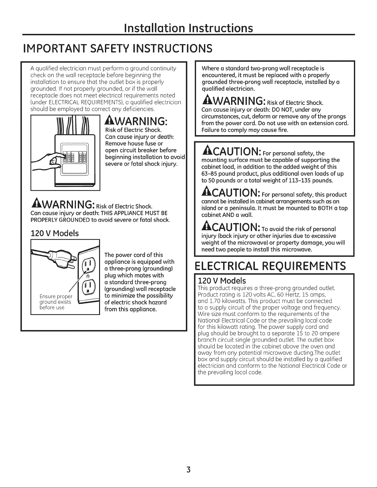
A qualified electrician must perform a ground continuity
check on the wall receptacle before beginning the
installation to ensure that the outlet box is properly
grounded. If not properly grounded, or if the wall
receptacle does not meet electrical requirements noted
(under ELECTRICALREQUIREMENTS),u qualified electrician
should be employed to correct any deficiencies.
WARNING:
Riskof Electric Shock.
Can cause injury or death:
Remove house fuse or
open circuit breaker before
beginning installation to avoid
severe or fatal shock injury.
J_,VV_I_I_I I I_i!tJ: Riskof Electric Shock.
Can cause injury or death: THISAPPLIANCEMUSTBE
PROPERLYGROUNDEDto avoid severe or fatal shock.
120 V Models
The power cord of this
appliance isequipped with
a three-prong {grounding)
plug which mates with
a standard three-prong
{grounding}wall receptacle
groond ex' sE
beforeuse
to minimize the possibility
of electric shock hazard
from this appliance.
Where a standard two-prong wall receptacle is
encountered, it must be replaced with a properly
grounded three-prong wall receptacle, installed by a
qualified electrician.
AWARN ING:RiskofElectricShock.
Can cause injury or death: DO NOT,under any
circumstances, cut, deform or remove any of the prongs
from the power cord. Do not use with an extension cord.
Failure to comply may cause fire.
Ar-^_ rrlr,_!
_L,_U||U|_: For personal safety, the
mounting surface must be capable of supporting the
cabinet load, in addition to the added weight of this
63-85 pound product, plus additional oven loads of up
to 50 pounds or a total weight of 113-135 pounds.
ACAUTION: For personal safety, this product
cannot be installed incabinet arrangements such as an
island or a peninsula. It must be mounted to BOTHa top
cabinet AND awall.
ACAUTION: Toavoidtheriskofpersonal
injury Iback injury or other injuries due to excessive
weight of the microwave) or property damage, you will
need two people to install this microwave.
ELECTRICAL REQUIREMENTS
120 V Models
This product requires athree-prong grounded outlet.
Product rating is 120 volts AC, 60 Hertz, 15 amps,
and 1.70 kilowatts. This product must be connected
to a supply circuit of the proper voltage and frequency.
Wire sizemust conform to the requirements of the
National Electrical Code or the prevailing local code
for this kilowatt rating. The power supply cord and
plug should be brought to a separate lS to 20 ampere
branch circuit single grounded outlet. The outlet box
should be located in the cabinet above the oven and
away from any potential microwave ducting.The outlet
box and supply circuit should be installed by a qualified
electrician and conform to the National Electrical Code or
the prevailing local code.
3
Page 4
Installation Instructions
HOOD EXHAUST
NOTE:Read these next two pages only if you plan to vent your exhaust to the outside.
If you plan to redrculate the air back into the room, proceed to page 6.
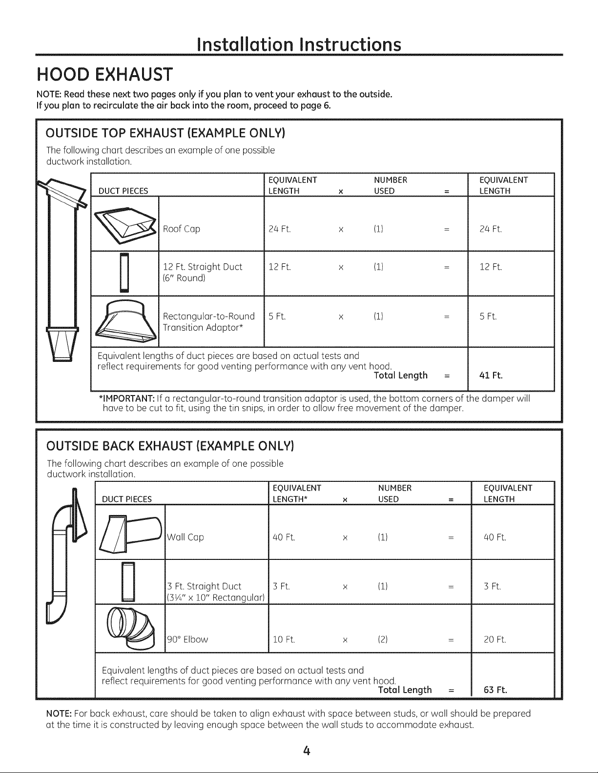
OUTSIDE TOP EXHAUST (EXAMPLE ONLY)
Thefollowing chart describes an example of one possible
ductwork installation.
EQUIVALENT NUMBER EQUIVALENT
DUCT PIECES
LENGTH x USED = LENGTH
Roof Cap
12 Ft.Straight Duct
D
Equivalent lengths of duct pieces are based on actual tests and
reflect requirements for good venting performance with any vent hood.
*IMPORTANT:If a rectangular-to-round transition adaptor is used, the bottom corners of the damper will
have to be cut to fit, using the tin snips, in order to allow free movement of the damper.
(6" Round)
Rectangular-to-Round
Transition Adaptor*
24 Ft. x (!)
12 Ft. x (!)
5 Ft. x (!)
OUTSIDE BACK EXHAUST (EXAMPLE ONLY)
The following chart describes an example of one possible
ductwork installation.
EQUIVALENT NUMBER EQUIVALENT
DUCT PIECES
LENGTH* x USED = LENGTH
Total Length
24 Ft.
12 Ft.
5 Ft.
41 Ft.
Wall Cap
3 Ft. Straight Duct
3¼" x !0" Rectangular)
40 Ft. x (!)
3 Ft. x (!)
40 Ft.
3 Ft.
[
90° Elbow
Equivalent lengths of duct pieces are based on actual tests and
reflect requirements for good venting performance with any vent hood.
NOTE:For back exhaust, care should be taken to align exhaust with space between studs, or wall should be prepared
at the time it is constructed by leaving enough space between the wall studs to accommodate exhaust.
!0 Ft. x (2)
Total Length
= 63 Ft.
4
20 Ft.
Page 5
Installation Instructions
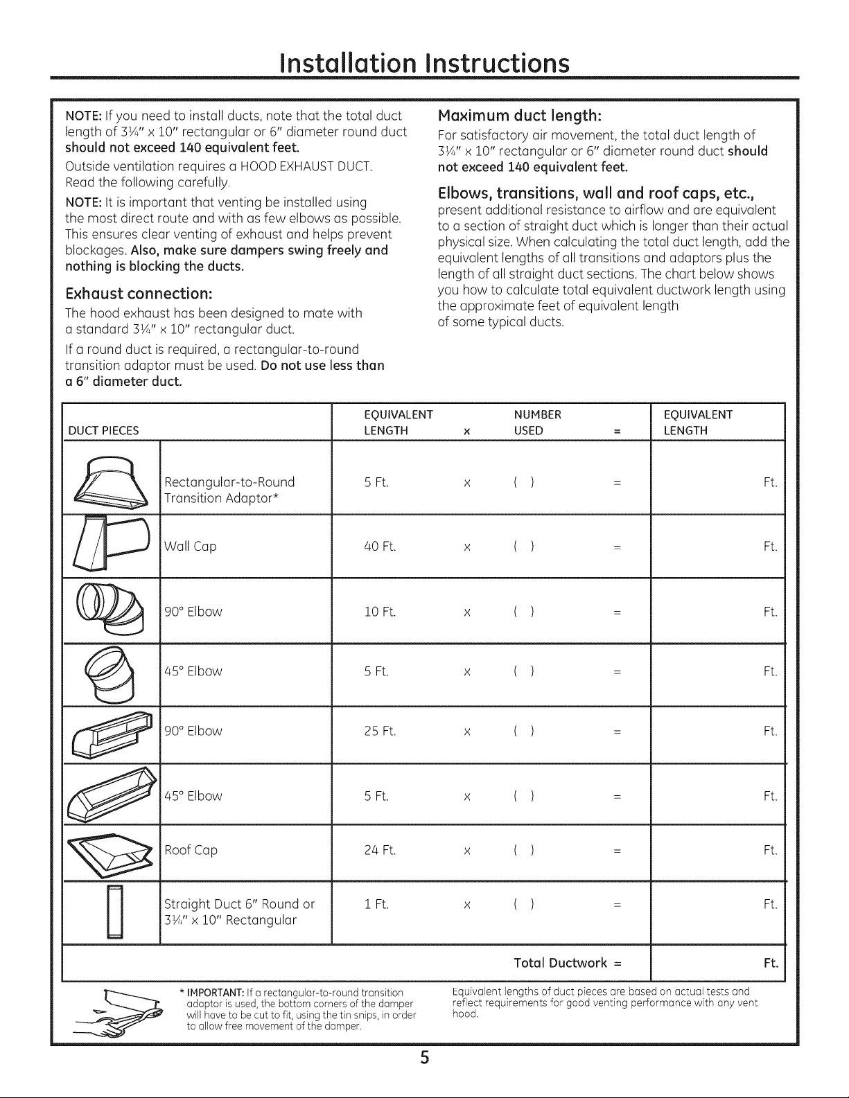
NOTE:If you need to install ducts, note that the total duct
length of 3¼" x 10" rectangular or 6" diameter round duct
should not exceed 140 equivalent feet.
Outside ventilation requires a HOODEXHAUSTDUCT.
Maximum duct length:
For satisfactory air movement, the total duct length of
3¼" x 10" rectangular or 6" diameter round duct should
not exceed 140 equivalent feet.
Read the following carefully.
NOTE:It is important that venting be installed using
the most direct route and with as few elbows as possible.
This ensures clear venting of exhaust and helps prevent
blockages. Also, make sure dampers swing freely end
nothing is blocking the ducts.
Exhaust connection:
The hood exhaust has been designed to mate with
a standard 3½" x 10" rectangular duct.
Elbows, transitions, wall and roof caps, etc.,
present additional resistance to airflow and are equivalent
to a section of straight duct which is longer than their actual
physical size.When calculating the total duct length, add the
equivalent lengths of all transitions and adaptors plus the
length of all straight duct sections. The chart below shows
you how to calculate total equivalent ductwork length using
the approximate feet of equivalent length
of some typical ducts.
If a round duct is required, a rectangular-to-round
transition adaptor must be used. Do not use less than
a 6" diameter duct.
EQUIVALENT NUMBER EQUIVALENT
DUCT PIECES LENGTH x USED = LENGTH
Rectangular-to-Round 5 Ft. ( ) Ft.
Transition Adaptor*
x
_ Wall Cap /40Ft. x ( ) : Ft.
(_ 90° Elbow 10 Ft. x ( ) = Ft.
(_ /45°Elbow 5 Ft. x ( ) = Ft.
90° Elbow 25 Ft. x ( ) = Ft.
_ /45 Elbow 5Ft. x ( ) = Ft.
Straight Duct 6" Round or 1 Ft. x ( ) = Ft.
3¼" x !0" Rectangular
Total Ductwork = Ft.
* IMPORTANT:If a rectangular-to-round transition Equivalent lengths of duct pieces are based on actual tests and
adaptor is used, the bottom corners of the damper reflect requirements for good venting performance with any vent
will have to be cut to fit, using the tin snips, in order hood.
to allow free movement of the damper.
5
Page 6
Installation Instructions
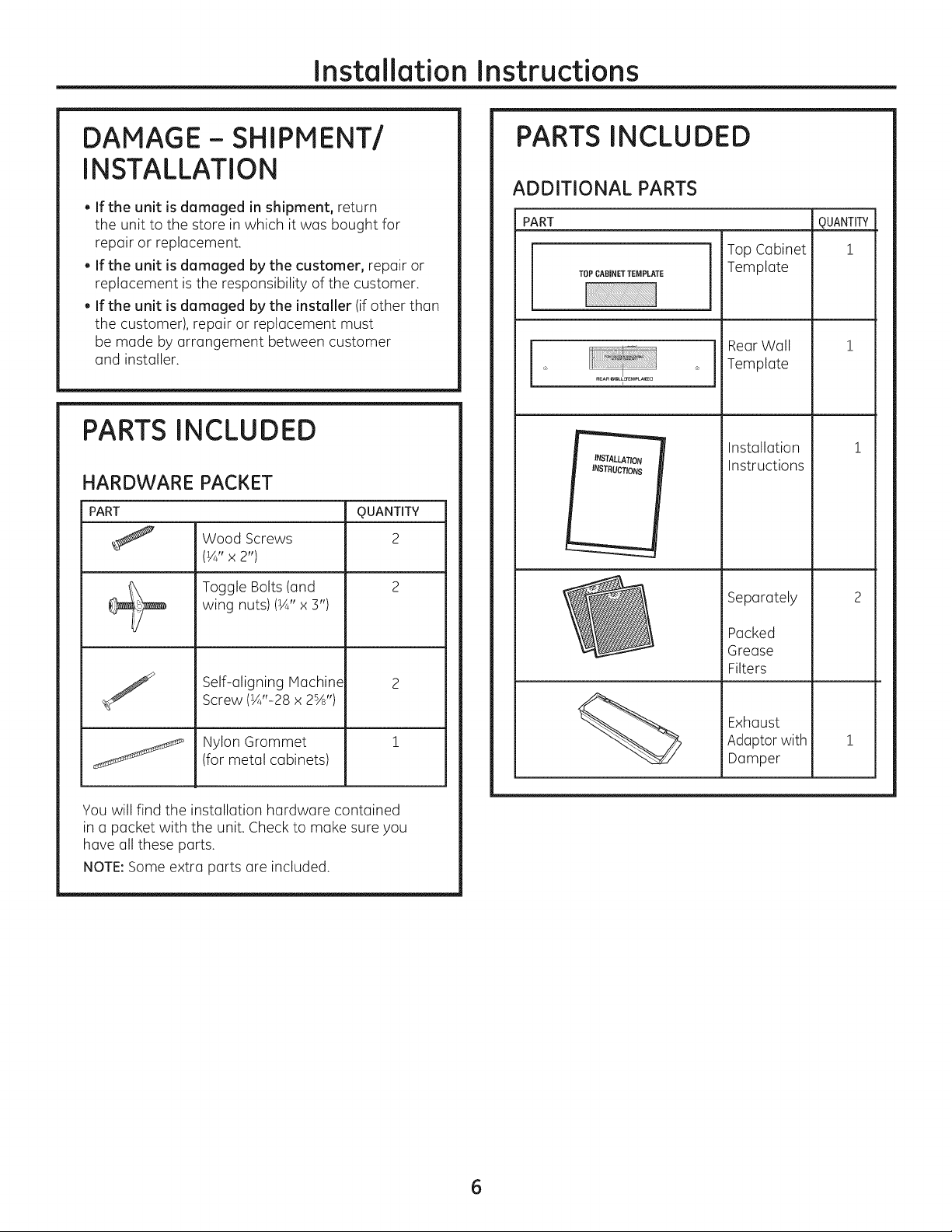
DAMAGE- SHIPMENT/
INSTALLATION
. If the unit is damaged in shipment, return
the unit to the store in which it was bought for
repair or replacement.
. If the unit is damaged by the customer, repair or
replacement is the responsibility of the customer.
. If the unit is damaged by the installer (if other than
the customer), repair or replacement must
be made by arrangement between customer
and installer.
PARTS INCLUDED
HARDWARE PACKET
PART
Wood Screws
(¼" x 2")
Toggle Bolts (and
wing nuts)(¼" x 3")
Self-aligning Machine
Screw (¼"-28 x 2%')
Nylon Grommet
(for metal cabinets)
QUANTITY
2
PARTS INCLUDED
ADDITIONAL PARTS
PART
TOPCABINETTEMPLATE
INSTALLATION
INSTRUCTIONS
Top Cabinet
Template
RearWall
Template
Installation
Instructions
Separately
Packed
Grease
Filters
Exhaust
Adoptor with
Damper
m
QUANTITY
i
i
You will find the installation hardware contained
in a packet with the unit. Check to make sure you
have all these parts.
NOTE:Some extra parts are included.
6
Page 7
Installation Instructions
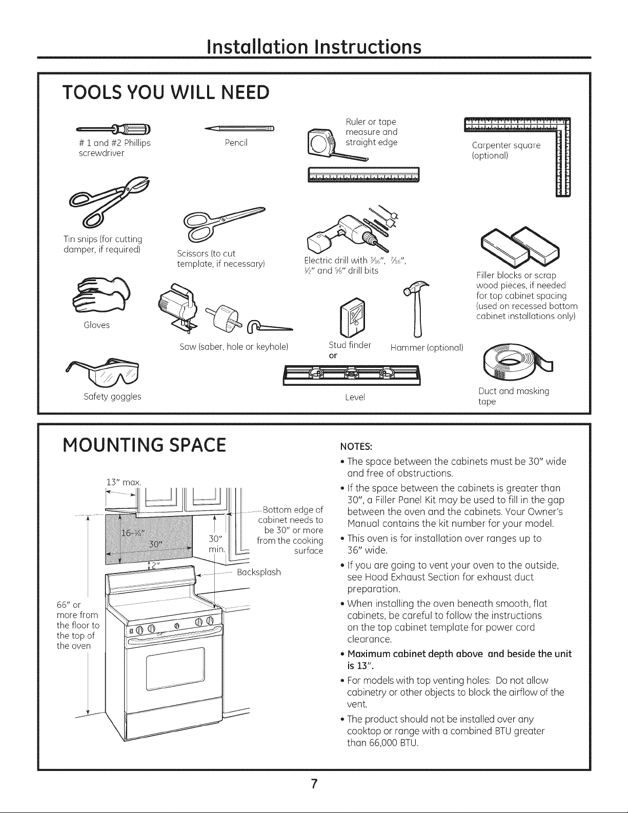
TOOLS YOU WILL NEED
# i and#2 Phillips Pencil
screwdriver
Tinsnips(for cutting
damper,if required)
Gloves
Scissors(tocut
template, if necessary)
Ruleror tape
measureand
ht edge
Electric drill with sad', 7Ad',
½" and %" drill bits
0
1
Carpentersquare
(optional)
¢5b
Fillerblocksorscrap
wood pieces,if needed
for top cabinet spacing
(usedon recessedbottom
cabinet installationsonly)
Saw(saber,holeor keyhole)
Safetygoggles
MOUNTING SPACE
66" or
morefrom
the floor to
the top of
the oven
..........Bottom edge of
cabinet needs to
be 30" or more
from the cooking
surface
Backsplash
Studfinder
or
Level
NOTES:
The space between the cabinets must be 30" wide
and free of obstructions.
If the space between the cabinets is greater than
30", a Filler Panel Kit may be used to fill in the gap
between the oven and the cabinets. Your Owner's
Manual contains the kit number for your model.
This oven is for installation over ranges up to
36" wide.
. If you are going to vent your oven to the outside,
see Hood Exhaust Section for exhaust duct
preparation.
. When installing the oven beneath smooth, flat
cabinets, be careful to follow the instructions
on the top cabinet template for power cord
clearance.
. Maximum cabinet depth above and beside the unit
is13".
. Formodels with top venting holes: Do not allow
cabinetry or other objects to block the airflow of the
vent.
. The product should not beinstalled over any
cooktop or range with a combined BTUgreater
than 66,000 BTU.
Hammer(optional)
Ductand masking
tape
Page 8
Instollotion Instructions
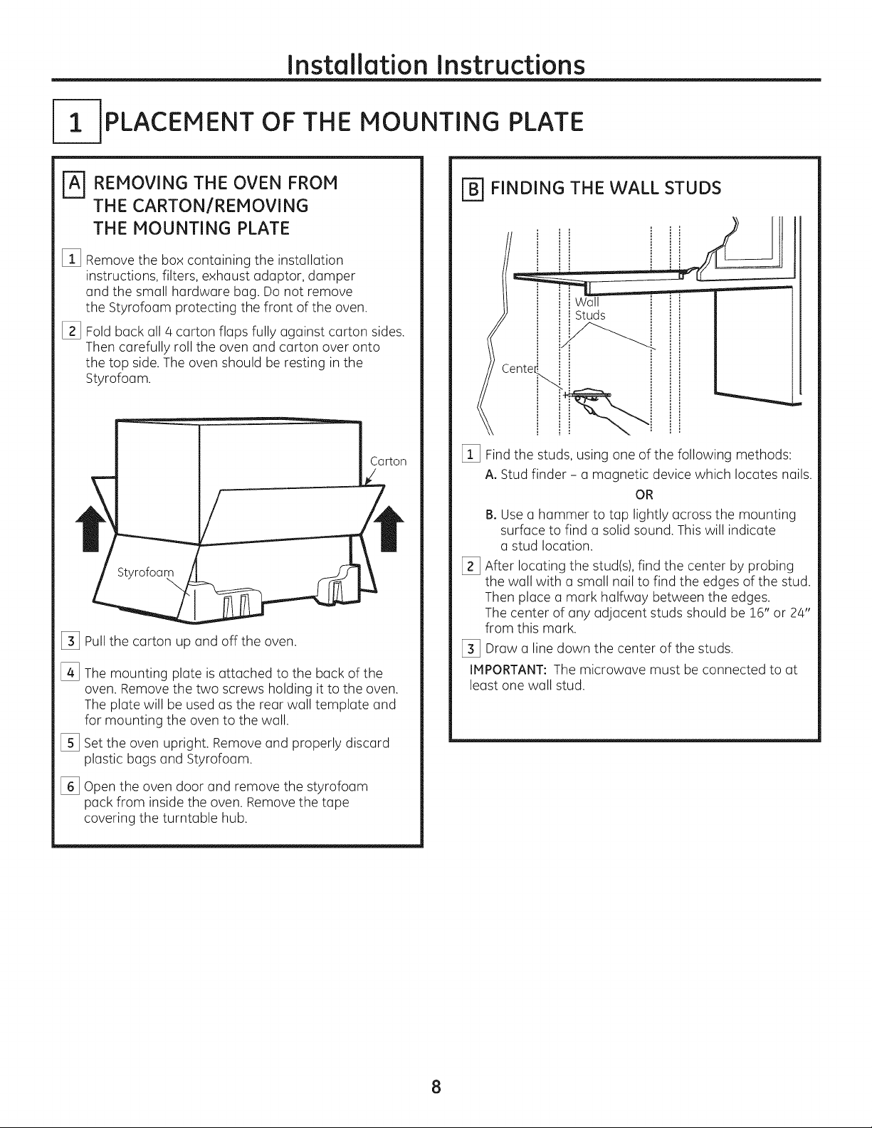
-IPLACEMENT OF THE MOUNTING PLATE
REMOVING THE OVEN FROM
THE CARTON/REMOVING
THE MOUNTING PLATE
%
Remove the box containing the installation
instructions, filters, exhaust adaptor, damper
and the small hardware bag. Do not remove
the Styrofoam protecting the front of the oven.
[]
Fold back all 4 carton flaps fully against carton sides.
Then carefully roll the oven and carton over onto
the top side.The oven should be resting in the
Styrofoam.
Styrofoam
%
Pullthe carton up and off the oven.
%
The mounting plate is attached to the back of the
oven. Remove the two screws holding it to the oven.
The plate will be used as the rear wall template and
for mounting the oven to the wall.
%
Setthe oven upright. Remove and properly discard
plastic bags and Styrofoam.
\
[_ FINDING THE WALL STUDS
Wall
Studs
Cente_
[_ Findthe studs, using one of the following methods:
A. Stud finder - a magnetic device which locates nails.
OR
B. Use a hammer to tap lightly across the mounting
surface to find a solid sound. This will indicate
a stud location.
[_ After locating the stud(s),find the center by probing
the wall with a small nail to find the edges of the stud.
Then place a mark halfway between the edges.
The center of any adjacent studs should be 16" or 24"
from this mark.
[_ Draw a line down the center of the studs.
IMPORTANT: The microwave must be connected to at
least one wall stud.
%
Open the oven door and remove the styrofoam
pack from inside the oven. Remove the tape
covering the turntable hub.
8
Page 9
Installation Instructions
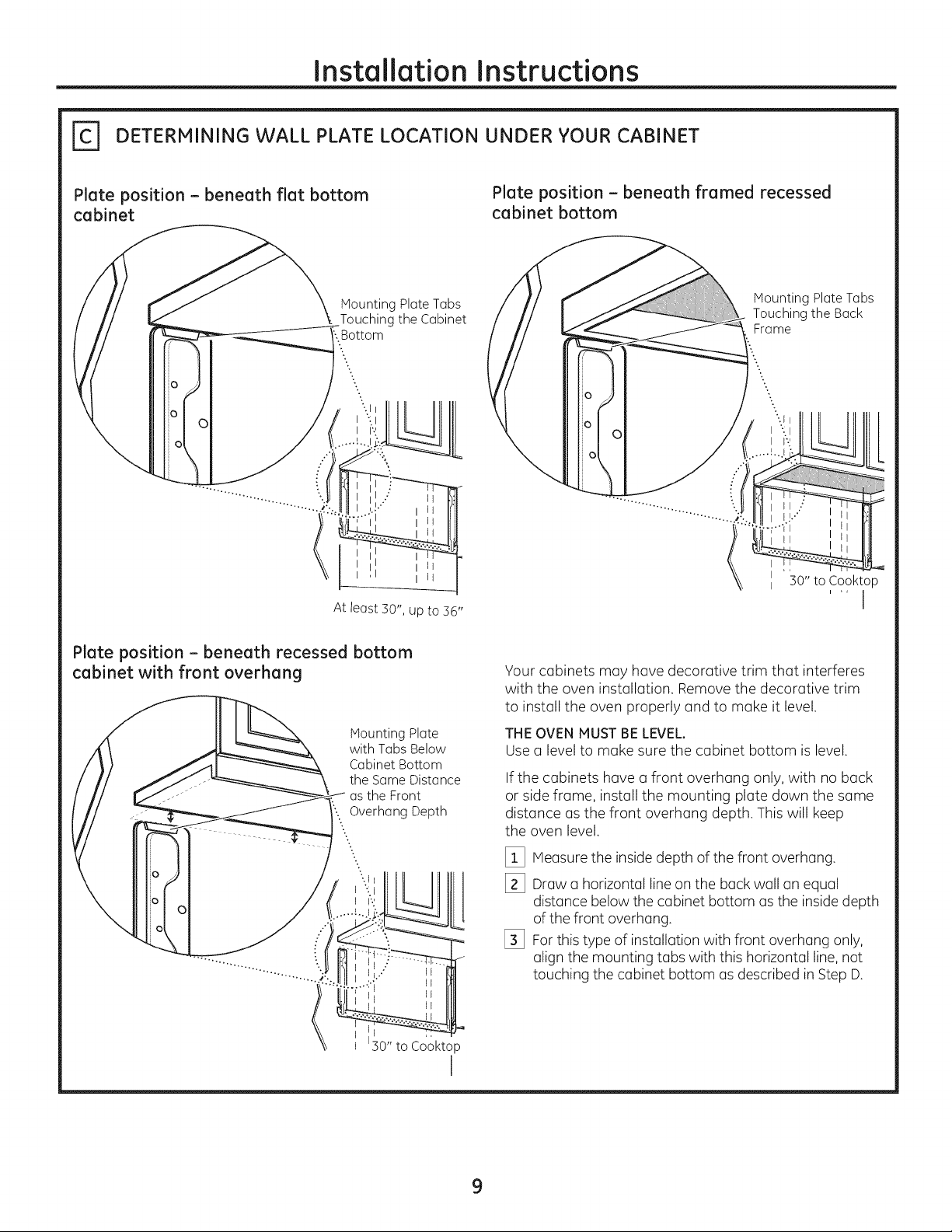
DETERMINING WALL PLATE LOCATION UNDER YOUR CABINET
Plate position - beneath flat bottom
cabinet
o
At least 30", up to 36"
MountingPlateTabs
Touching theCabinet
:.Bottom
Plate position - beneath framed recessed
cabinet bottom
Mounting Plate Tubs
Touching the Back
Frame
II "30" to Cooktop
i ,, I
Plate position - beneath recessed bottom
cabinet with front overhang
MountingPlate
with TabsBelow
CabinetBottom
the SameDistance
asthe Front
'....Overhang Depth
..
..
-..
0
0
C
;0" to Cooktop
Your cabinets may have decorative trim that interferes
with the oven installation. Remove the decorative trim
to install the oven properly and to make it level.
THE OVEN MUST BE LEVEL.
Use (] level to make sure the cabinet bottom is level.
If the cabinets have (]front overhang only, with no back
or side frame, install the mounting plate down the some
distonce us the front overhung depth. This will keep
the oven level.
[_ Measure the inside depth of the front overhung.
[_ Draw (] horizontal line on the buck wall tin equal
l
distance below the cabinet bottom usthe inside depth
of the front overhung.
[_ For this type of installation with front overhung only,
align the mounting tubs with this horizontal line,not
touching the cabinet bottom us described in Step D.
I
9
Page 10
Installation Instructions
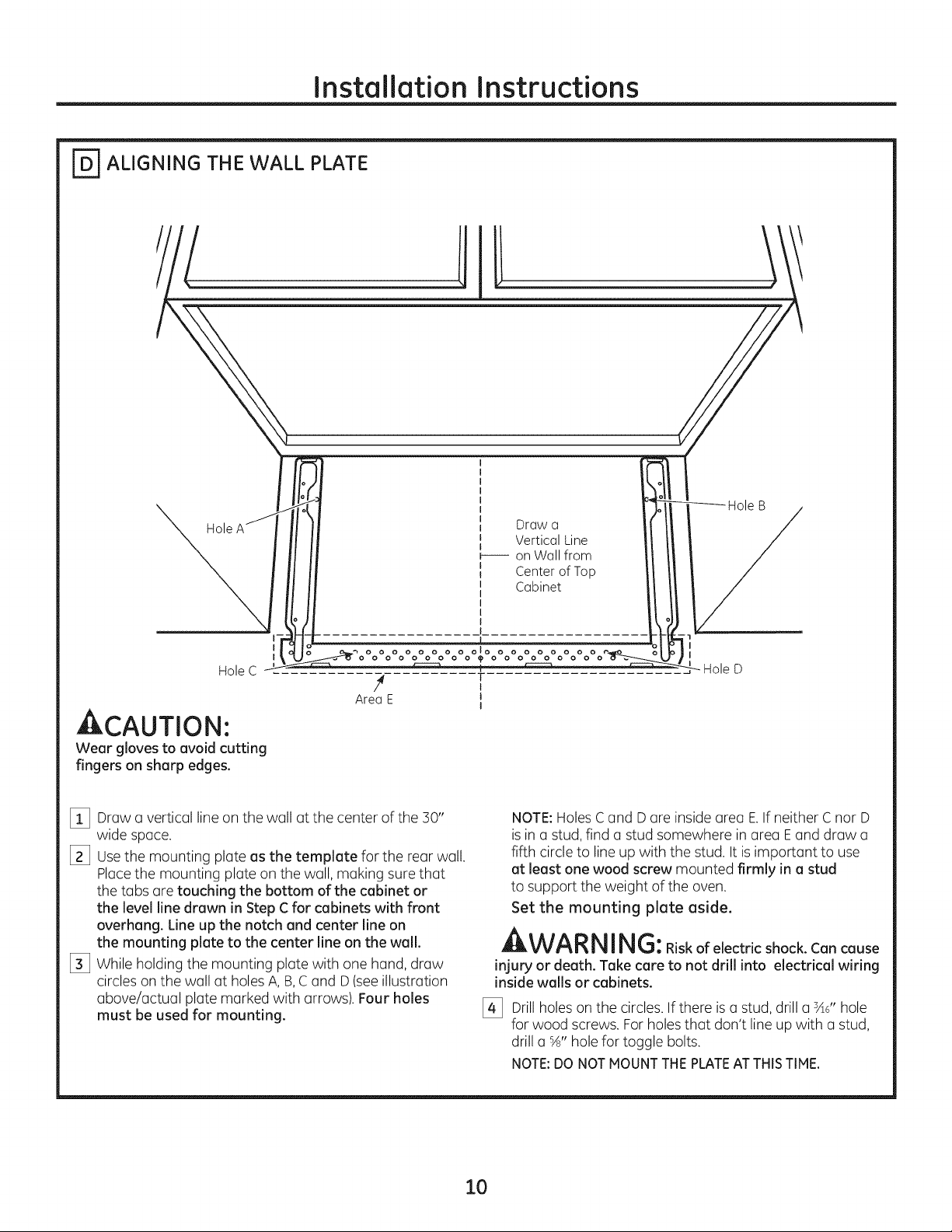
_ ALIGNING THE WALL PLATE
Hole
I
I
Hole C
4 T
AreaE J
ACAUTION'.
Wear glovestoavoidcutting
fingerson sharpedges.
[_ Drawa vertical line on the wall at the center of the 30"
wide space.
[_ Usethe mounting plate as the template for the rear wall.
Placethe mounting plate on the wall, making sure that
the tabs are touching the bottom of the cabinet or
the level line drawn in Step C for cabinets with front
overhang. Line up the notch and center line on
the mounting plate to the center line on the wall.
[_ While holding the mounting plate with one hand, draw
circles on the wall at holes A, B,Cand D(see illustration
above/actual plate marked with arrows). Four holes
must be used for mounting.
Draw o
Vertical Line
b---- on Wall from
Center of Top
Cabinet
olo
I
I
NOTE:Holes Cand D are inside area E.If neither C nor D
isin astud, find a stud somewhere in area Eand draw a
fifth circle to line up with the stud. It is important to use
at least one wood screw mounted firmly in a stud
to support the weight of the oven.
Set the mounting plate aside.
A WARNING:Riskofelectricshock.Cancause
injury or death. Take care to not drill into electrical wiring
inside walls or cabinets.
[_ Drill holeson the circles. If there is a stud, drill a sad'hole
for wood screws. For holes that don't line upwith a stud,
drill a %" hole for toggle bolts.
NOTE:DONOTMOUNTTHEPLATEAT THISTIME,
10
Page 11
Installation Instructions
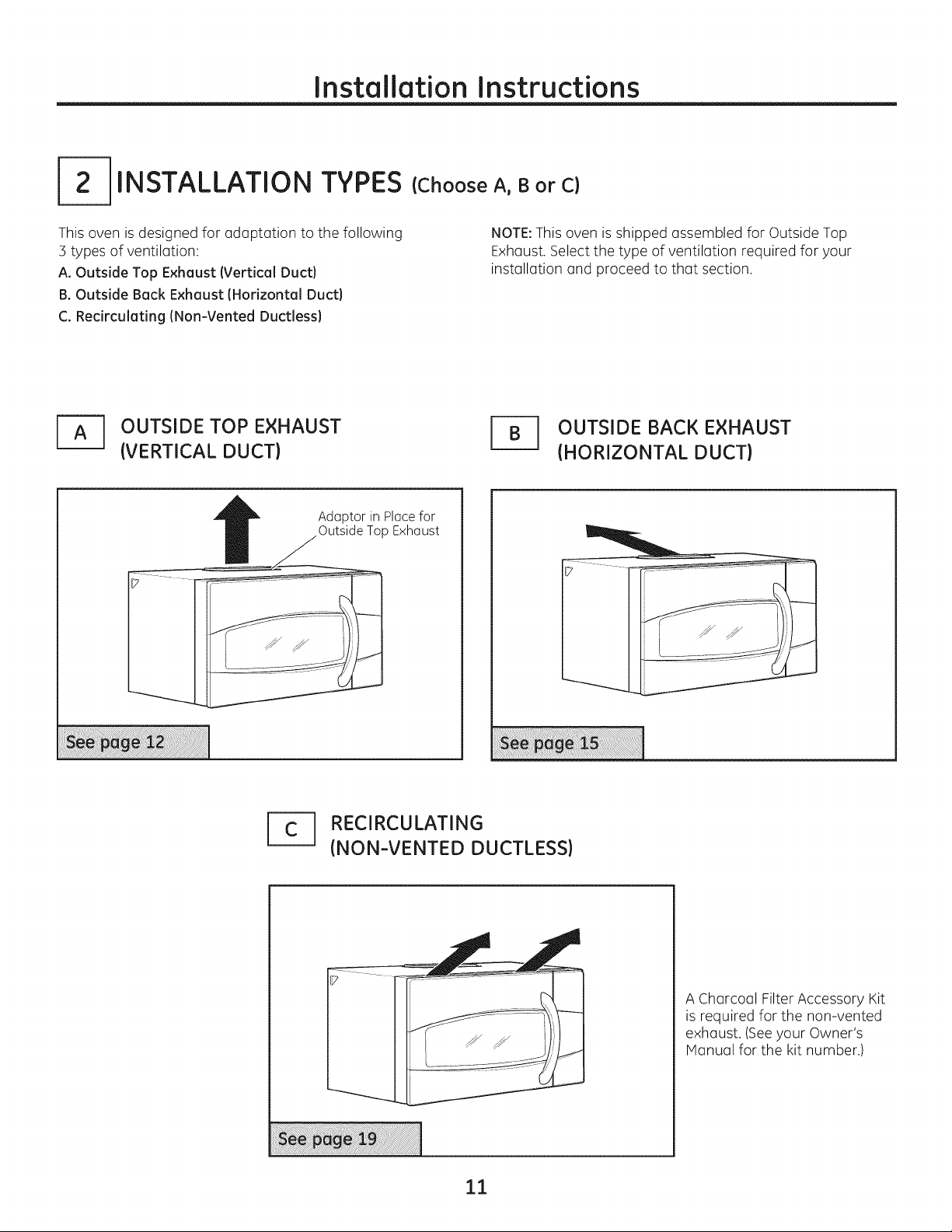
INSTALLATION TYPES
This oven is designed for adaptation to the following
3 types of ventilation:
A. Outside Top Exhaust (Vertical Duct)
B. Outside Back Exhaust (Horizontal Duct)
C. Recirculating (Non-Vented Ductless)
J_ OUTSIDE TOP EXHAUST
(VERTICAL DUCT)
Adaptor in Ploce for
Outside Top Exhaust
(Choose A, B or C)
NOTE:This oven is shipped assembled for Outside Top
Exhaust. Select the type of ventilation required for your
installation and proceed to that section.
r_ UTSIDE BACK EXHAUST
(HORIZONTAL DUCT)
1_ RECIRCULATING
(NON-VENTED DUCTLESS)
A Charcoal Filter Accessory Kit
is required for the non-vented
exhaust. (Seeyour Owner's
Manual for the kit number.)
11
Page 12
Installation Instructions
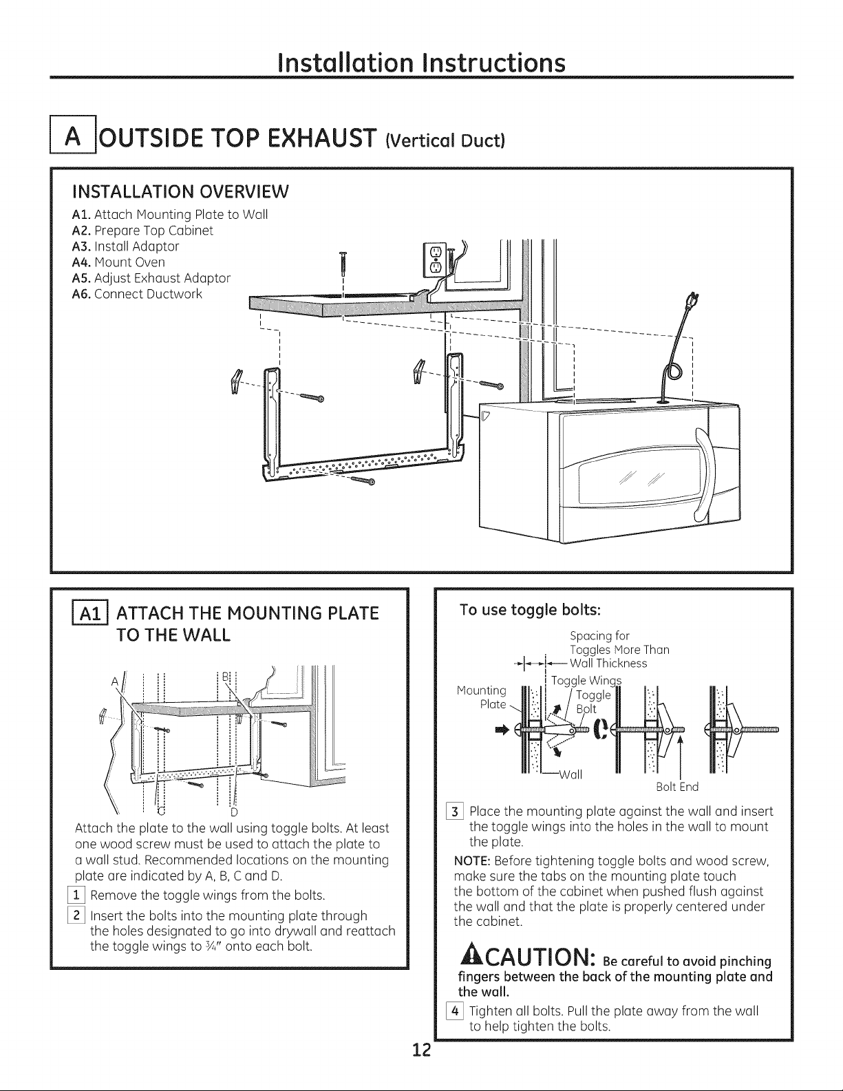
IA-IOUTSIDE TOP EXHAUST (Vertical Duct)
INSTALLATION OVERVIEW
AI. Attach Mounting Plate to Well
A2. Prepare Top Cabinet
A3. Install Adaptor
A4. Mount Oven
AS.Adjust Exhaust Adaptor
A6. Connect Ductwork
ATTACH THE MOUNTING PLATE
TO THE WALL
i B
Attach the plate to the well using toggle bolts. At least
one wood screw must be used to attach the plate to
a wall stud. Recommended locutions on the mounting
plate are indicated by A, B,C and D.
[_ Remove the toggle wings from the bolts.
[_ Insert the bolts into the mounting plate through
the holes designated to go into drywall end reattach
the toggle wings to ¾" onto each bolt.
To use toggle bolts:
Spacing for
Toggles More Then
"_l_,-k_-- Wall Thickness
Mounting
i Toggle Wing_
Bolt End
[_ Place the mounting plate against the wall and insert
the toggle wings into the holes in the wall to mount
the plate.
NOTE:Before tightening toggle bolts and wood screw,
make sure the tabs on the mounting plate touch
the bottom of the cabinet when pushed flush against
the wall and that the plate is properly centered under
the cabinet.
LIILI_,I"_UIIIIJI_I: Be careful to avoid pinching
fingers between the back of the mounting plate and
the wall.
[_ Tighten all bolts. Pull the plate away from the wall
to help tighten the bolts.
12
Page 13
Installation Instructions
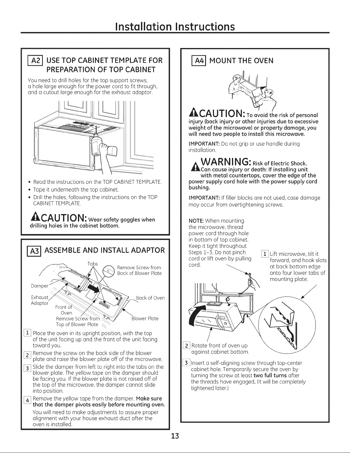
_USE TOP CABINET TEMPLATE FOR
PREPARATION OF TOP CABINET
You need to drill holes for the top support screws,
a hole large enough for the power cord to fit through,
and a cutout large enough for the exhaust adaptor.
. Read the instructions on the TOPCABINETTEMPLATE.
. Tape it underneath the top cabinet.
Drillthe holes, following the instructions on the TOP
CABINETTEMPLATE.
A,--^l i-rill,!
Wearsafetygoggleswhen
drilling holes in the cabinet bottom.
FA=-_ASSEMBLE AND INSTALL ADAPTOR
Tabs
Back of Blower Plate
_ Remove Screw from
/-j,
Da
_ MOUNT THE OVEN
CAUTI e riskofpersonal
injury (back injury or other injuries due to excessive
weight of the microwave) or property damage, you
will need two people to install this microwave.
IMPORTANT:Do not grip or use handle during
installation.
A WA RNING:RiskofElectricShock.
Can cause injury or death: If installing unit
with metal countertops, cover the edge of the
power supply cord hole with the power supply cord
bushing.
IMPORTANT:If filler blocks are not used, case damage
may occur from overtightening screws.
NOTE:When mounting
the microwave, thread
power cord through hole
in bottom of top cabinet.
Keep it tight throughout
Steps 1-3. Do not pinch
cord or lift oven by pulling
cord.
[_ Lift microwave, tilt it
forward, and hook slots
at back bottom edge
onto four lower tabs of
mounting plate.
Exhaust_q_-_
Adaptor" _ "'_C_-:
[_ Placethe oven in its upright position, with the top
of the unit facing up and the front of the unit facing
toward you.
[_ Remove the screw on the back side of the blower
plate and raise the blower plate off of the microwave.
[_ Slide the damper from left to right into the tabs on the
blower plate. The yellow tape on the damper should
be facing you. If the blower plate is not raised off of
the top of the microwave, the damper cannot slide
into position.
[_ Remove the yellow tape from the damper. Make sure
that the damper pivots easily before mounting oven.
You will need to make adjustments to assure proper
alignment with your house exhaust duct after the
oven is installed.
Front o'f_
Oven
Remove Screw
Topof BlowerPlate
¢ Back of Oven
__wer Plate
[_ Rotate front of oven up
against cabinet bottom.
[_ Insert a self-aligning screw through top-center
cabinet hole. Temporarily secure the oven by
turning the screw at least two full turns after
the threads have engaged. (Itwill be completely
tightened later.)
13
Page 14
Installation Instructions
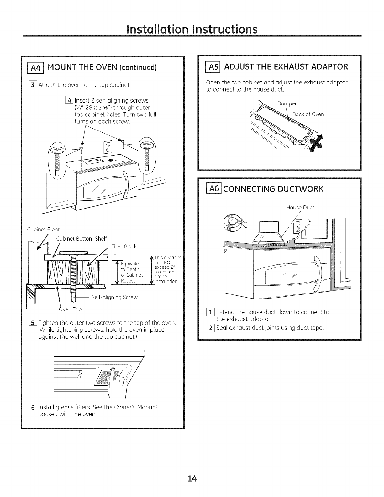
_ MOUNT THE OVEN Icontinued}
[_ Attach the oven to the top cabinet.
[_ Insert 2 self-aligning screws
(¼"-28 x 2 %') through outer
top cabinet holes.Turn two full
turns on each screw.
Cabinet Front
Cabinet Bottom Shelf
FillerBlock
_=5] ADJUST THE EXHAUST ADAPTOR
Open the top cabinet and adjust the exhaust adaptor
to connect to the house duct.
Damper
Back of Oven
_6] CONNECTING DUCTWORK
House Duct
--_--Equivalent / can NOT
I i° Depth /to ensure
I of Cabinet |proper
_'nstallation
-- Self-Aligning Screw
Oven Top
[] Tighten the outer two screws to the top of the oven.
(While tightening screws, hold the oven in place
against the wall and the top cabinet.)
..............................................................................................111 i _],
[_ Install grease filters. Seethe Owner's Manual
packed with the oven.
,/
_This distGnce
exceed 2"
[_ Extend the house duct down to connect to
the exhaust adaptor.
[_ Seal exhaust duct joints using duct tape.
14
Page 15
Installation Instructions
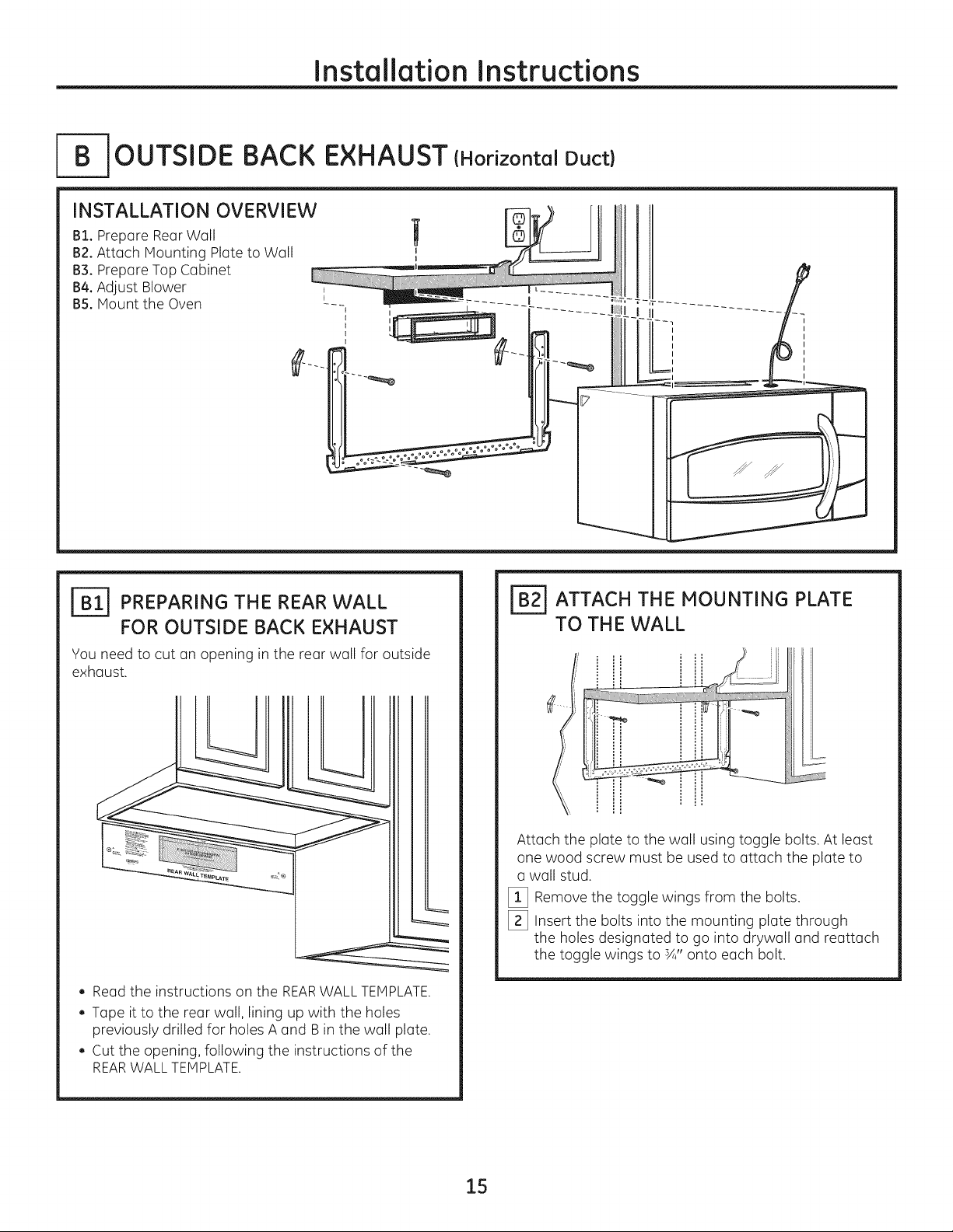
_--B-JOUTSIDE BACK EXHAUST (Horizontal Duct)
INSTALLATION OVERVIEW
B1. Prepare Rear Wall
B2.Attach Mounting Plate to Wall
B3°Prepare Top Cabinet
B4.Adjust Blower ,
BS.Mount the Oven --- _i_
.L
12
J_ PREPARING THE REAR WALL
FOR OUTSIDE BACK EXHAUST
You need to cut an opening in the rear wall for outside
exhaust.
, Read the instructions on the REARWALLTEMPLATE.
, Tape it to the rear wall, lining up with the holes
previously drilled for holes A and B in the wall plate.
, Cut the opening, following the instructions of the
REARWALL TEMPLATE.
FB_ ATTACH THE MOUNTING PLATE
TO THE WALL
!i
,, i......3'!! i
Attach the plate to the wall using toggle bolts. At least
one wood screw must be used to attach the plate to
a wall stud.
[_ Remove the toggle wings from the bolts.
[_ Insert the bolts into the mounting plate through
the holes designated to go into drywall and reattach
the toggle wings to sA"onto each bolt.
15
Page 16

Installation Instructions
To use toggle bolts:
Spacing for Toggles More
-_l_-_-,_--Than Wall Thickness
Mounting Toggle Wings
Platemj__"
Bolt End
[_ Place the mounting plate against the wall and insert
the toggle wings into the holes in the wall to mount
the plate.
NOTE:Before tightening toggle bolts and wood screw,
make sure the tabs on the mounting plate touch
the bottom of the cabinet when pushed flush against
the wall and that the plate is properly centered under
the cabinet.
CAUTI0 N:Be carefultoavoidpinching
fingersbetweenthe backofthemounting
plateand thewall.
[_ Tighten all bolts. Pull the plate away from the wall
to help tighten the bolts.
I-_ ADAPTING BLOWER FOR
OUTSIDE BACK EXHAUST
[_ Remove the blower motor screw that holds the
blower plate to the oven. Lift the front of the blower
plate to install the blower.
MotorScrew
Blower '___ BlowerPlate
...... _O_o_rscrew
[_ Carefully pull out the blower unit. Thewires
will extend far enough to allow you to adjust
the blower unit.
End
r_USE TOP CABINET TEMPLATE
FOR PREPARATION OF TOP
CABINET
Vou need to drill holes for the top support screws and
a hole large enough for the power cord to fit through.
. Read the instructions on the TOP CABINET
TEMPLATE.
. Tape it underneath the top cabinet.
. Drill the holes, following the instructions on the
TOP CABINET TEMPLATE.
_L,t'_U/IIU |_l: Wear safety goggles when
drilling holes in the cabinet bottom.
[_ Rotate blower unit counterclockwise 180°.
Before Rotation After Rotation
lack of ,
Oven
[_ Gently remove the wires from the grooves.
Reroute the wires through grooves on other side
of the blower unit.
Before Rerouting After Rerouting
Wires Routed Through Right
Side
Wires RoutedThroughLeft
Side
Oven
16
Page 17

Installation Instructions
I_ Roll the blower unit 90° so that fan blade openings
are facing out the back of the oven.
BeforeRolling
Backof
Oven
Locate the two "knockout" plates, on the rear oven
%
panel, near the top of the oven.
Using tin snips, carefully cut the web area from the
two holes side-by-side (that secure the knockouts to
the oven). Cut all four webs on both rear knockouts;
this will allow the ventilation fan airflow to exhaust
out the rear of the oven.
After Rolling
Back of
Oven
A,--^l I-T-i,-__m
Jlbt'_U|| _-.Jl_l : Be sure to trim the sharp
edges from the openings after removing the
knockout plates.
I_ Attach the exhaust adaptor to the rear of the oven
by sliding it into the guides at the top center of the
back of the oven.
Exhaust Ad%tor Damper
Slide
exhaust
adaptor into
guides on
oven re%.
Pushdown securely until it is in the lower locking
tabs. Take care to assure the damper hinge
is installed so that it is at the top and that the
damper swings freely.
[_ Close the blower plate so it is closed over the top
tab of the exhaust adapter. Secure with the screw
removed earlier.
BlowerPlate
Tabs Guides
\
(hinge side up)
Back of
Oven
Back of
Oven
Snip all 4 webs
on each knockout
panel and
remove the metal
knockouts for rear
airflow.
[_ Place the blower unit back into the opening.
WA RNING:Riskofelectricshock
can cause injury or death. Do not pull or stretch
the blower unit wiring, make sure the wires are
not pinched..
NOTE:The blower unit exhaust openings should
match exhaust openings on rear of microwave.
Screw
Exhaust Adaptor
17
Page 18

[_ MOUNT THE OVEN
Installation Instructions
Cabinet Front
Cabinet Bottom Shelf
FillerBlock
ACAUTI ' risk of personal
injury (back injury or other injuries due to excessive
weight of the microwave) or property damage, you
will need two people to install this microwave.
IMPORTANT: Do not grip or use handle during
installation.
ING:
kWAR N RiskofElectricShock.
Can cause injury or death: If installing unit
with metal countertops, cover the edge of the
power supply cord hole with the power supply cord
bushing.
IMPORTANT:If filler blocks are not used, case damage
may occur from overtightening screws.
NOTE:When mounting
the microwave, thread
power cord through hole
in bottom of top cabinet.
Keep it tight throughout
Steps !-3. Do not pinch
cord or lift oven by pulling
cord.
[_ Lift microwave, tilt it
forward, and hook slots
at back bottom edge
onto four lower tabs of
mounting plate.
TEquiva]ent | can NOT
I to Depth |exceed 2"
I of Cabinet |to ensure
I _ / proper
_'nstollotion
-- Self-Aligning Screw
OvenTop
[_ Attach the oven to the top cabinet.
[_ Insert 2 self-aligning screws
(¼"-28 x 2 %') through outer
top cabinet holes.Turn two full
turns on each screw.
_This distance
[_ Rotate front of oven up
against cabinet bottom.
[_ Insert a self-aligning screw through top-center
cabinet hole. Temporarily secure the oven by
turning the screw at least two full turns after
the threads have engaged. (It will be completely
tightened later.)
[] Tighten the outer two screws to the top of the
oven. (While tightening screws, hold the oven
in place against the wall and the top cabinet.)
II I
/
[_ Install grease filters. Seethe Owner's Manual
packedwiththeoven.
18
Page 19

Installation Instructions
]RECIRCULATING (Non-Vented Ductless}
INSTALLATION OVERVIEW
C1. Attach Mounting Plate to Wall
C2. Prepare Top Cabinet
C3. Adjust Blower
C4oMount the Oven
C5. Install Charcoal Filter (Supplied with
JNM!95! and PNM!97! models)
I
I
I
ATTACH THE MOUNTING PLATE
TO TH E WALL
Attach the plate to the wall using toggle bolts. At least
one wood screw must be used to attach the plate to
a wall stud.
[] Remove the toggle wings from the bolts.
[_ Insert the bolts into the mounting plate through
the holes designated to go into drywall and reattach
the toggle wings to ¾" onto each bolt.
To use toggle bolts:
Spacing for
Toggles More Then
÷J-_-_,-,----We Thickness
lToc
Mounting
[_ Place the mounting plate against the wall and insert
the toggle wings into the holes in the wall to mount
the plate.
NOTE:Before tightening toggle bolts and wood screw,
make sure the tabs on the mounting plate touch the
bottom of the cabinet when pushed flush against the
wall and that the plate is properly centered under the
cabinet.
ACAUTION: Be careful toavoidpinching
fingers between the back of the mounting plate and
the wall.
[_ Tighten all bolts. Pull the plate away from the wall
to help tighten the bolts.
USETOP CABINET TEMPLATE
FOR PREPARATION OF TOP CABINET
You need to drill holes for the top support screws and
a hole large enough for the power cord to fit through.
. Read the instructions on the TOPCABINET
TEMPLATE.
. Tape it underneath the top cabinet.
. Drill the holes, following the instructions on the TOP
CABINETTEMPLATE.
Bolt End
At-^l rT-mr,_,
Llkl_,l'%IJll11J|_I:Wear safety goggles when
drilling holes in the cabinet bottom.
19
Page 20

Installation Instructions
r_ ADAPTING BLOWER
FOR RECIRCULATION
NOTE:The exhaust adaptor with damper is not
needed for recirculating models. You may want
to save them for possible future use.
[_ Carefully pull out the blower unit. The wires
will extend far enough to allow you to adjust
the blower unit.
___ BlowerPlate
[_ Carefully pull out the blower unit. The wires
will extend far enough to allow you to adjust
the blower unit.
End B
[_ Placethe blower unit back into the opening.
AWA RNING: Riskofelectricshock
can cause injury or death. Do not pull or stretch
the blower unit wiring. Make sure the wired are
not pinched.
[_ Close the blower plate. Secure with the screw
removed earlier.
Blower Plate
Back of
Oven
Screw
[_ Roll the blower unit 90° so that fan blade openings
are facing out the back of the oven.
jj
.----->'] JM;;'* /
_--...-/--' ff%-YBack o;f
Backiof
Over_
NOTE:Make sure wires remain routed in the grooves
of the motor frame.
2O
Page 21

Installation Instructions
_4-1 MOUNT THE OVEN
CAUTION: Toavoidtheriskofpersonal
injury (back injury or other injuries clue to excessive
weight of the microwave) or property damage, you
will need two people to install this microwave.
IMPORTANT:Do not grip or use handle during
installation.
t WARN ING:RiskofElectricShock.
Can cause injury or death: If installing unit
with metal countertops, cover the edge of the
power supply cord hole with the power supply cord
bushing.
IMPORTANT:If filler blocks are not used, case damage
may occur from overtightening screws.
[_] Insert a self-aligning screw through top-center
cabinet hole. Temporarily secure the oven by
turning the screw at least two full turns after
the threads have engaged. (Itwill be completely
tightened later.)
Cabinet Front
Cabinet Bottom Shelf
Filler Block
TEquivaJent Jcan NOT
[ to Depth |exceed 2"
| of Cabinet |to ensure
_[.Recess $ proper..
_Ins_ollo_lon
-- Self-Aligning Screw
Oven Top
[_ Insert 2 self-aligning screws
(¼"-28 x 2%") through outer
top cabinet holes.Turn two full
turns on each screw.
_This distance
NOTE:When mounting
the microwave, thread
power cord through hole
in bottom of top cabinet.
Keep it tight throughout
Steps !-3. Do not pinch
cord or lift oven by pulling
cord.
[_] Rotate front of oven up
against cabinet bottom.
[_] Lift microwave, tilt it
forward, and hook slots
at back bottom edge
onto four lower tabs of
mounting plate.
[] Tighten the outer two screws to the top of the
oven. (While tightening screws, hold the oven
in place against the wall and the top cabinet.)
[_] Install grease filters. See the Owner's Manual
packed with the oven.
21
Page 22

Installation Instructions
INSTALLING THE CHARCOAL
FILTER
[_ Remove 2 screws on top of oven,just above
the grille panel, using a Phillips screwdriver.
[_ Open the door.
[_ Remove the grille.
j Screws
Grille
?
[_ Insert the filter into the oven us shown until it fits
squarely into place. It will rest at an angle behind
the front lower tabs. When properly installed,
the wire mesh of the filter should be visible
from the front.
lowertabs
J
f
Charcoal filter
I_ Replace the grille and the 2 top screws.
[_ Close the door and replace left side screw.
22
Page 23

Installation Instructions
BEFORE YOU USE YOUR OVEN
Make sure the oven has been installed
according to instructions.
Remove all packing material from the oven.
. =
[_] Read the Owner's Manual.
r_ EEPINSTALLATIONINSTRUCTIONS
FORTHE LOCALINSPECTOR'SUSE.
[_] Replace house fuse or turn breaker back on.
120 V Models: Plug power cord into
a dedicated 15- to 20-amp electrical outlet.
Ensure proper
ground exists
before use.
Where a standard two-prong wall receptacle
is encountered, it is very important to have it
replaced with a properly grounded three-prong
wall receptacle, installed by a qualified
electrician.
23
Page 24

24
Printed in Korea
Page 25

I strucci
de i stal
ANTES DE EMPEZAR
Homo para colocar
enclma de la estufa
JVM1950, JNM1951, PVM1970, PNM1971
y PVM2170
Leo estos instrucciones completo y cuidodosomente.
. IMPORTANTE - Guardeestos
instrucciones poro el uso clel inspector local.
. IMPORTANTE - Cump,ocontodos,os
c6digos y orclenonzes gubernumenteles.
. Not° par° el instalador - Aseg0resede dejor
estes instrucciones con el consumidor.
, Not° par° el consumidor - Guarde estus
instrucciones poro futuru referenciu.
, Nivel de destrezas - Lo instoloci6n de esteuporoto
requiere de destrezus b6sicus de mecc_nicuy electricidud.
, Lo instoluci6n upropiudu es responsubilidud
del instulodor.
L° folla del producto debido ° una instaloci6n
inapropiad° no est6 cubiert° por I0 garant[°.
49-40641-i
09-11 GE
LEA CUIDADOSAMENTE.
GUARDE ESTAS INSTRUCCIONES.
Page 26

Instrucdonesde instalaci6n
CONTENIDO
Informaci6n general
Instrucciones de seguridad importantes ......................3
Requisitos el_ctricos ........................................................3
Campana de escape ....................................................4, 5
Da_os - Envio / Instalaci6n ............................................6
Partes incluidas ................................................................6
Herramientas que necesitar6 ........................................7
Espacio de montaje ..........................................................7
Guia de instalaci6n paso por paso
C6mo colocar el plato de montaje ..........................8-10
C6mo remover el plato de montaje ........................8
C6mo encontrar madera s61ida
en la pared ...........................................................................8
C6mo determinar la Iocalizaci6n
de las placas de la pared .............................................9
[_ Recirculaci6n ............................................................!9-22
C6mo adherir la placa de
montaje a la pared ............................................19
Preparaci6n del gabinete superior .............19
C6mo adaptar el soplador
para la recirculaci6n ..................................20,21
C6mo montar el homo ............................21, 22
C6mo instalar el filtro de carbonilla ..........22
Antes de comenzar a usar su homo .........................23
C6mo alinear la placa de la pared .......................10
Tipos de instalaci6n .................................................11-22
[_ Escape superior .....................................
C6mo adherir la placa de
montaje a la pared ............................................12
Preparaci6n del gabinete superior ............13
Ensamblaje e instalaci6n
del adaptador ......................................................13
C6mo montar el homo .............................13, 14
C6mo ajustar el adaptador de escape....14
C6mo conectar el conducto .........................14
[_ Escape posterior externo ...................................
C6mo preparar la pared posterior
para el escape posterior exterior ...............15
C6mo adherir el plato de
montaje a la pared .....................................15, 16
Preparaci6n del gabinete superior ............16
exterior 12-14
15-18
C6mo adaptar el soplador para
el escape posterior exterior ....................16,17
C6mo montar el homo ....................................18
Page 27

Instruccionesde instalaci6n
NSTRUCCIONES DE SEGURIDAD
Este producto requiere un tomacorriente el_ctrico
de tres patas conectado a tierra. El instalador debe
Ilevar a cabo una inspecci6n de continuidad a tierra
en la caja el6ctrica antes de comenzar la instalaci6n
para asegurar que la caja tomacorriente est6 conectada
a tierra de manera apropiada. Si no Io est6, o si
el tomacorriente no cumple con los requisitos
el@ctricos indicados (bajo la secci6n REQUISITOS
ELECTRICOS),se deber6 recurrir a un t@cnico
calificado para corregir cualquier deficiencia.
A PRECAUCi6N:
Para seguridad personal,
remueva el fusible de la casa
o abra el interruptor de circuito antes
de comenzar la instalaci6n
para evitar descargas el6ctricas
severas o fatales
ADVERTENCIA:Riesgo de Descarga
El_ctrica. Puede ocasionar lesiones o la muerte: ESTE
ELECTRODOMI_STiCO SE DEBE CONECTAR A TiERRA DE
FORMA CORRECTA a fin de evitar descargas severas o
mortales.
Modelos de 120 V
El cable de corriente de este
electrodom_stico contiene
un enchufe de 3 patas
(conexi6n a tierra} que se
conecta a un tomacorriente
cont_rconun_
antes de usan
de pared est6ndar de 3
cables (conexi6n a tierra}
para minimizar la posibilidad
de riesgos de descargas
el_ctricas par parte del
mismo.
IMPORTANTES
Cuando se encuentre un tomacorrientede pared de
dos enchufes,se deber6 reemplazar par uno de tres
cablesconectado a tierrade farinaadecuada, y deber6
serinstaladopar un electricistacalificado.
ADVERTENCIA:Riesgo de Descarga
El_ctrica. Puede ocasionar lesiones o la muerte: NUNCA,
bajo ninguna circunstancia, carte, deforme o elimine
ninguna de las puntas de los cables de corriente. No use
un prolongador. Si no se cumple con esto, se podr6n
producir incendios.
Annrr^l lrl_km
_P'_E_#'_UL, IV|_: Por razones de
seguridad, la superfide de montaje deber6 poder
soportar la carga del gabinete, sumado al peso
agregado de este producto de entre 63 y 85 libras,
adem6s de cargas adicionales en el homo de hasta 50
libras o un peso total de entre 113 y 135 libras.
PRECAUCION: parrazonesde
seguridad, este producto no se puede instalar en
arreglos de gabinete tales coma una isla o peninsula. Se
debe montar TANTO a un gabinete superior COHO a
una pared.
s
PRECAUCION: A deevitarelriesgo
de lesi6n personal (lesi6n en la espalda u otras lesiones
debido a peso e×cesivo del horno de microondas} o
daffos sabre el producto, deber6 contar con la ayuda de
dos personas para instalar este horno de microondas.
REQUISlTOS ELI CTRICOS
Modelos de 120 V
La clasificaci6n del producto es de 120 vatios CA(AC),
60 hertz, 15 amperios, y 1.70 kilovatios. Este producto
debe estar conectado a un circuito de suministro del
voltaje y frecuencia apropiados. Eltama_o del alambre
debe conformarse a los requisitos del National Electric
Code o al c6digo local en efecto para este fndice
de kilovatios. Elcable el_ctrico de alimentaci6n y el
interruptor deber6n Ilevarse a un tomacorriente 6nico
conectado a tierra de 15 a 20 amperios, La caja del
tomacorriente deber6 estar Iocalizada en elgabinete
encima del horno. La caja del tomacorriente debe
ser instalada por un electricista calificado y debe
conformarse al National Electrical Code o al c6digo
local en efecto.
3
Page 28

Instruccionesde instalaci6n
CAMPANA DE ESCAPE
NOTA:Lea las siguientes dos p6ginas solamente si planea ventilar el escape hacio el exterior.
Si por el contrario planea recircular el aire de vuelta hacia el sal6n, contin6e en la p6gina 30.
ESCAPE SUPERIOR EXTERNO {EJEMPLO SOLAMENTE)
La siguiente tabla describe un ejemplo de una posible
instalaci6n de red de conductos.
LONGITUD NUMERO
PARTES DEL CONDUCTO
Tapa del techo
Conducto recto de
EQUIVALENTE x USADO
24 pies x (!)
12 pies x (!)
12 pies (redondo de 6")
de rect6nguloa redondo*
Adaptador de transici6n 5 pies x (!) : Spies
LaIongituddelaspartes de los conductosequivalentesest6basadaenpruebasrealesy
reflejanlos requisitospara Iograr una buenaventilaci6ncon cualquiercampanade escape.
*IMPORTANTE:Sise usa un adaptador de transici6n de rect6ngulo a redondo, las esquinas del fondo
del regulador de tiros deber6n cortarse para que encajen, usando las tUerasde corte, para permitir
el movimiento libre del regulador de tiros.
ESCAPE POSTERIOR EXTERNO (EJEMPLO SOLAMENTE)
LONGITUD
EQUIVALENTE
24 pies
12 pies
Longitud total = 41 pies
La siguiente tabla describe un ejemplo de una posible
instalaci6n de red de conductos.
NOMERO
USADO
(!)
(!)
LONGITUD
EQUIVALENTE
40 pies
:3pies
PARTESDELCONDUCTO
Tapa de pared
Conducto recto de
LONGITUD
EQUIVALENTE
40 pies
:3pies
x
x
3 pies (rectangular de
3¼" x 10")
wT_
(_ Codo de 90° !0 pies x (2) = 20 pies
La Iongitud de las partes de los conductos equivalentes est6 basada en pruebas reales y
reflejan los requisitos para Iograr una buena ventilaci6n con cualquier campana
de escape. Longitud total = 621pies
NOTA:Para el escape posterior, se debe tenet cuidado al alineqr el escape entre los espados de los postes de riga de fa pared, o la pared deberiq ser
preparadaenelmomentodesuconstrucd6ndejqndosufidenteespadoentrelospostesderigadelaparedparaacomodarelescape.
4
Page 29

Instruccionesde instalaci6n
NOTA:Siusted necesita instalar conductos, tenga pendiente
que la Iongitud total del conducto rectangular de 3¼" x 10"
o el conducto redondo de 6" dedi6metro no debe
sobrepasar 140 pies equivalentes.
La ventilaci6n externa requiere un CONDUCTODECAMPANA
Longitud m6xima del conducto:
Para Iograr un movimiento satisfactorio del aire, la
Iongitud total del conducto rectangular de 3¼" x 10"
o el conducto redondo de 6" de di6metro no debe
sobrepasar 140 pies equivalentes.
DEESCAPE.LeaIosiguiente cuidadosamente.
NOTA:Esimportante que laventilaci6n sea instalada usando
la ruta mas directa y con la menor cantidad decodes posible.
Estoasegura laventilaci6n delescape y ayuda a prevenir
bloqueos.Tambi_n,cerci6resedeque elreguladordetire
pendelibrementey nada bloquealosconductos.
Conexiones de escape:
La campana de escape ha sidediseBada para encajar con
un conducto rectangular de 3_4"x !0" estandar.
Siun conducto redondo esnecesario,sedebe usar
Los codes, transiciones, paredes y tapes
de techo, etc., presentan resistencia adicional al flujo
de aire y son equivalentes a una secci6n de conducto
recto el cual es m6s largo que su tamaho fisico real.
Cuando calcule la Iongitud total del conducto, agregue
las longitudes equivalentes de todas las transiciones
y adaptadores, m6s la Iongitud de todas las secciones
de conducto rectas. La tabla m6s adelante muestra
c6mo puede calcular la Iongitud aproximada de la red
de conductos usando pies aproximados de longitudes
equivalentes de algunos conductos t[picos.
un adaptador de transici6n de rectangular a redondo.
No use un conducto menor de 6" de diametro.
LONGITUD NUMERO LONGITUD
PARTES DE CONDUCTO EQUIVALENTE × USADO = EQUIVALENTE
Adaptador de transici6n de 5 pies x ( ) : pies
rect6ngulo a redondo*
Tapa de pared 40 pies x ( ) = pies
pies
x
()_ Code de 90° 10 ( )
Code de 45° 5 pies x ( ) = pies
Code de 90° 25 pies x ( ) = pies
_ Codode45 ° 5 ( )
pies
x
Tape detecho 24 pies x ( ) = pies
Conductorectode 6" redondo 1 pies x ( ) = pies
o rectangular de 3½" x 10"
pies
pies
Reedde conductos Total = pies
rect6ngula e redondo,las esquinas del fondo del regulador en pruebas reales y reflejan los requisites para Iograr una buena
de tiros deber6n sercortadas pare que encejen, usando ventilaci6n con cualquier campana de escape.
* IMPORTANTE:Sise usa un adaptador detransici6n de LaIongitud de las partes de conductos equivalentes est6 basada
lostijeras de carte, pera permitir el movimiento libre del
regulador de tiros.
5
Page 30

Instrucdonesde instalaci6n
DANOS- ENV[O /
INSTALAClON
. Si la unidad se daffa durante el envio, devuelvG
IGunidGd GI GImGc6n clonde IG Gdquiri6 pGrG
SUrepGrGci6n o reemplGzo.
. Si el cliente dafia la unidad, IG repGrGci6n
o el reemplazo es responsGbilidGd clel cliente.
. Si el instalador dafia la unidad (si no es el cliente),
IGrepGrGci6n o reemplGzo se clebe hGcer por meclio
de un Grreglo entre el cliente y el instGIGdor.
PARTES INCLUIDAS
PAQUETE DE ELEHENTOS
PARTE
+
Tornillos de madera 2
(1A"x 2")
Tornillos basculantes 2
(ytuercas de mariposa)
(1A"x 3")
Tornillos de m6quina 2
autoalineables
(1A"-28 x 2%')
Arandela aislante de 1
nil6n (para gabinetes
metdlicos)
CANTIDAD
PARTES INCLUIDAS
PARTES ADICIONALES
PARTE
Plantilla para
TOPCABINETTEMPLATE
INSTALLATION
INST_IIlCTION 8
%
el gabinete
superior
Plantilla para
la pared
posterior
lnstrucciones
de instalaci6n
Filtros de
grasa
empacados
por separado
Adaptador
del escape &
Regulador
de tiro
CANTIDAD
!
1
1
2
1
Usted encontrar6 los elementos de instalaci6n en
un paquetejunto con Io unidod. Inspeccione poro
cerciorarse de que tiene todos los portes.
NOTA:Se incluyen olgunos portes odicionoles.
Page 31

Instruccionesde instalaci6n
HERRAMIENTAS
Destornilladoresde
estrella# iy # 2
Tijeras para cortar lat6n
(para cortar el regulador
de tiro, si es necesario)
Guantes
Tijeras(paracortar la
plantilla,sies necesario)
Sierra(desable,agujero,o de
ojode cerradura)
OUE
L6piz
NECESITARA
_ Regla recta y cinta
Taladro el@ctrico con brocas
deYS, 74d',½"y %"
Detectorde
postesde viga o (opcional)
Escuadra de
carpintero
(opcional)
Bloques de relleno o
pedazos de madera, si son
necesarios para rellenar
el gabinete (usados
solamente en la instalaci6n
de gabinetes apoyados)
un martillo
Gafas de seguridad
ESPAClO DE MONTAJE
13" max.
66" o m6s
desde el
piso hasta
la parte
superior
del homo
El extremo del
del gabinete
necesita estar a
30" o m6s a partir
de la superficie de
Protectorposterior
de salpicacturas
la estufa
Nivel
NOTAS:
. Elespacio entre los gabinetes debe set de 30"
de ancho y debe estar libre de obstrucciones.
. Siel espacio entre los gabinetes es mayor de
301 un "Filler Panel Kit" podrfa set necesario para
rellenar las brechas entre el homo y los gabinetes.
Su Manual del Propietario contiene el nOmero de
kit para su modelo.
Este homo es para set instalado por encima de
estufas hasta 36" de ancho.
. Si usted se dispone a ventilar su horno hacia el
exterior, ver la Secci6n de Campana de Escape
para la preparaci6n del conducto de escape.
. Cuando se instale el horno debajo de gabinetes
de rondos lisos y pianos, tenga cuidado de seguir
cuidadosamente las instrucciones en la plantilla
del gabinete superior para el espacio de tolerancia
del cable el6ctrico.
. La profundidad del gabinete por encima y al
costado de la unidad es de 13".
. Para modelos con hoyos de ventilaci6n superiores:
No permita que el gabinete u otros objetos
bloqueen el flujo de aire de la ventilaci6n.
. El producto no debe instalarse sobre ninguna
estufa o cocina con una combinaci6n superior
a 66,000 BTU.
Cinta de conductos o cinta
adhesiva protectora
Page 32

Instruccionesde instalaci6n
C6MO COLOCAR EL PLATO DE MONTAJE
[_] C6MO REMOVER EL HORNO
DEL EMBALAJE / C6MO REMOVER
EL PLATO DE MONTAJE
%
Remueva lu cajo que contiene las instrucciones
de instulaci6n, los filtros, el adaptador de escape,
el regulador de tiro y la peque_a balsa con los
elementos de instalaci6n. No remueva lu espuma
de poliestireno que protege el frente del horno.
[]
Pliegue hacia atr6s las alas de la caja. Luego,
cuidadosumente ruede el homo husta que quede
apoyado sabre la parte superior. Elhomo deber6
descansar sabre la espuma de poliestireno.
Poliestireno
\
[_ Tire de la caja hacia arriba y retfrela del horno.
%
Elpluto de montaje est6 pegado u la parte posterior
del homo. Remueva los dos tornillos que Io sostienen
pegado al homo. El plato ser6 usado coma la plantilla
de la pared posterior y para montar el homo a la
pared.
I_ Pare elhomo. Remueva y descarte de manera
apropiada las balsas pl6sticas y el poliestireno.
[_ Abru la puerta del homo y remueva el paquete de
espuma de poliestireno del interior. Remueva la
cinta adhesiva que cubre el aro giratorio.
IBI C6MO ENCONTRAR LOS POSTES
DE VIGA EN LA PARED
Pastesdevig_
en la pared i
Centr%_
[_ Encuentre los pastes, usando uno de los
m@odos siguientes:
A. Useun detector de pastes - un dispositivo
magn@ico que Iocaliza clavos.
0
B. Use un martillo para golpear ligeramente a trav6s
de la superficie de montaje hasta encontrar un
sonido s61ido.Esto indicar6 que hay un paste de
riga en ese lugar.
Despu6s de Iocalizar el paste o los pastes de riga,
%
encuentre el centro mediante el an61isisde la pared
usando un clara pequeBo para darse cuenta de
d6nde est6n los bordes del paste. Luego coloque
una marca en el centro de los bordes. Elcentro de
cualquier paste adyacente deber6 ser entre Z6" 6 24"
desde esta marca.
[_ Trace una linea hacia abajo indicando el centro
del paste.
IMPORTANTE:Elhomo de microondas se deber6
conectar a par Io menos un montaje de pared.
8
Page 33

Instruccionesde instalaci6n
_C7 C6MO DETERMINAR LA LOCALIZACION DEL PLATO DE MONTAJE DEBAJO
DE SU GABINETE
Posici6n del plato - debajo de gabinetes
de rondo plano
Las orejillas del plato
de montaje tocan el
fondo del gabinete
o
°oIO
Por to menos 30", hasta 36"
Posici6n del plato - debajo de gabinetes
de rondo apoyado en un marco
Las orejillas del
plato de montaje
tocan el marco
posterior
30""hasta la estufa
Posici6n del plato - debajo de gabinetes
de fondo apoyado con frente saliente
30" hasta la estufa
Plato de montaje
con orejillas por
debajo del fondo
del gabinete a la
misma distancia
la profundidad
del saliente
Susgabinetes podrfan tener marcos de decoraci6n
que interfieran con la instalaci6n del horno. Remueva
los marcos decorativos para instalar el homo
apropiadamente y para hacer que quede nivelado.
ELHORNO DEBE QUEDARNIVELADO.
Use un nivel para cerciorarse de que el fondo
del gabinete est6 nivelado.
Si los gabinetes tienen un saliente frontal solamente,
sin marco posterior o lateral, instale el plato de montaje
a la misma distancia de la profundidad del saliente.
Este mantendr6 el homo nivelado.
[] Mida la profundidad interna del frente del saliente.
[_ Trace una linea horizontal en la pared posterior
a una distancia debajo del fondo del gabinete igual
a la profundidad interna del frente saliente.
[_ Para estetipo de instalaci6n con salientefrontal
solamente, alinee las orejillas de montaje con lalinea
horizontal, sin tocar el fondo del gabinete como
sedescribi6 en el Paso D.
9
Page 34

Instrucdonesde instalaci6n
_'] C6MO ALINEAR EL PLATO DE MONTAJE SABRE LA PARED
Agujero
.................. J..................
Agujero C
I
O0OO0000100000000
000o0o00_00000o00
7........T
Area E J
PRECAUCION:
Use guantes de protecci6n
para evitar cortaduras en sus
dedos con los extremes filosos.
[] Trace una linea vertical en la pared en el centre
del espacio de:SO"de ancho.
[_ Useel plato de montaje coma la plantilla pare la pared
posterior. Coloque el plato de montaje en la pared,
cercior6ndose de qua las orejillas se encuentran tocando
el fondo del gabinete ola linea marcada en el Paso C
pare los gabJnetes con salientes frontales. Alinee
la muesca y linea del centre en el plato de montaje
con la linea de centre en la pared.
[_ Wlientrassostiene el plato demontaje con una mane,
trace circulos en la pared en los agujeros A, B,Cy D
(verla ilustraci6n anterior / laplaca real est6 marcada
con flechas). Deben usarse cuatro agujeros para
el montaje.
Traceuna linea
vertical en la
pareda partirdel
_--centro del gabinete
superior
_Agujero B
/
Agujero D
I
NOTA:Los agujeros Cy Dvan en elinterior del 6rea E.
Si ni el C ni el D est6n en un paste de viga, encuentre
un paste en algOnotro lugar en el6rea Ey marque
un quinto drculo para alinearse con el paste.
Esimportante usar par Io menos un tornillo de madera
montado firmemente en un paste para apoyar elpeso
del horno.
Aparte el plato de montaje.
ADVERTENClA: Riesgodedescarga
el_ctrica. Puede provocar lesiones o la muerte. Tenga
cuidado de no perforar el cableado el_ctrico ubicado
dentro de las parades o gabinetes.
[_ Per[ore agujeros en los circulos. Si hay un paste de
riga, per[ore un agujero de 3/16" para los tornillos de
madera. Para los agujeros qua no quedaron alineados
con el paste de riga, perfore un agujero de 5/8" para
los families basculantes.
NOTA: TODAViA NO MONTE EL PLATO.
10
Page 35

Instruccionesde instalaci6n
I--2-JTIPOS DE INSTALACI6N
Este homo est6 dise_ado para adaptarse a los siguientes
tres tipos de ventilaci6n:
A.Escape superiorexterior (Conducto vertical)
B. Escape posterior exterior (Conducto horizontal)
C. Recirculaci6n (Sin conducto de ventilaci6n)
j_ SCAPE SUPERIOR EXTERIOR
(CONDUCTO VERTICAL)
Eladaptador est6
ensu lugar para
escapesuperior
exterior
(Escoja A, Bo C)
NOTA:Este homo es enviado ya ensamblado para un escape
superior exterior. Seleccione el tipo de ventilaci6n requerido
para su instalaci6n y proceda a tal secci6n.
J_ SCAPE POSTERIOR EXTERIOR
(CONDUCTO HORIZONTAL)
j_----j REClRCULACI6N
(SIN CONDUCTO DE VENTILACI6N)
11
Un Kit de accesorios de filtro
de carbonilla es necesario
para el sistema sin ventilaci6n.
(Consulte su Manual del
Propietario para obtener
el nOmero del kit.)
Page 36

Instrucdonesde instalaci6n
ESCAPESUPERIOR EXTERIOR(Conducto vertical)
PERSPECTIVA GENERAL
DE LA INSTALACION
AI. Como adherir el plato de montaje
a la pared
A2. Prepare el gabinete superior
A3. Instale el adaptador
A4. Monte el homo
A5. Ajuste el adaptador
de escape
A6. Conecte el conducto
COMO ADHERIR LA PLACA
DE MONTAJE A LA PARED
Af _ !! i!iMj !
i ii :'
Pegue el plato a la pared usando los tornillos
basculantes. Por Io menos un tornillo de madera debe
set usado para pegar el plato al poste de la pared. Las
ubicaciones recomendadas sobre la placa de montaje
se indican enA, B, Cy D.
[] Remueva las mariposas del basculante de los
tornillos.
[_ Inserte los tornillos en el plato de montaje atrav6s
de los agujeros dise_ados para ser insertados en
la pared de mamposteria seca y pegue otra vez
las mariposas desA"en cada tornillo.
Para usar los tornillos basculantes:
Espaciadoresparalos
basculantesmayores
÷_.-_j_--J que elanchode lapared
Plato de
monta
[_ Coloque el plato de montaje contra la pared e inserte
las alas de mariposa en los agujeros de la pared para
montar el plato.
NOTA:Antes deapretar los tornillos basculantes
y lostornillos demadera, cerci6rese de que las orejillas
en el plato de montaje toquen el fondo del gabinete
cuando son empujadas contra la pared y de que el plato
est6 centrado apropiadamente debajo del gabinete.
A "
PRECAUCION:Tenga cuidadode evitar
pellizcarsusdedos entrelaparteposteriordelplato
de montajey lapared.
[_ Apriete todos los tornillos. Tire del plato
en direcci6n opuesta a la pared para ayudar
a apretar los tornillos.
i Alasde mariposa
"_-Pared
Extremodeltornillo
12
Page 37

Instruccionesde instalaci6n
_USE LA PLANTILLA DEL GABINETE
SUPERIOR PARA LA PREPARACI6N
DEL GABINETE SUPERIOR
Deber6 perforar agujeros para los tornillos de apoyo
superiores, un agujero suficientemente grande para que
el cable el#ctrico quepa, y un recorte Iosuficientemente
grande como para que el adaptador de escape pueda
set introducido.
, Lea las instrucciones sobre la PLANTILLA
DELGABINETESUPERIOR.
, P_guelo debajo del gabinete superior.
, Taladre los agujeros, siguiendo las instrucciones
en la PLANTILLADELGABINETESUPERIOR.
PRECAUCION:Use gafas de seguridad
cuando perfore los agu]eros en el fondo del gabinete.
COMOMONTAR EL HORNO
PREC de evitar eJ
riesgo de lesi6n personal {Jesi6n en Ja espaJda u
otras Jesiones debido a peso excesivo deJ homo
de microondas) o daBos sobre eJproducto,
deber6 contar con la ayuda de dos personas
pare instalar este homo de microondas.
IMPORTANTE:No tome ni use la manija durante la
instalaci6n.
, ADVERTENCIA: Riesgode
Descarga El_ctrica. Puede ocasionar lesiones o la
muerte: si instala la unidad con encimeros de metal,
cubra el agujero del extremo del cable de suministro
de corriente con aislante para el cable del suministro
de corriente.
IMPORTANTE: Si no se usan bloqueadores de filtro,
se podr6n producir dahos en la caja debido al ajuste
excesivo de los tornillos.
_-_ ENSAMBLAJE E INSTALACION
DEL ADAPTADOR
Orejillas
Regulador
de tiro -%
Adaptadc
de escape
Frented
Horno
Retire el tornillo en la parte
superior del plato del soplador
[_ Coloque el horno en su posici6n vertical, con la parte
superior de la unidad hacia arriba y elfrente hacia usted.
Retire el tornillo en la parte trasera del plato soplador y
[_ retire el mismo del homo microondas.
Deslice el regulador de izquierda a derecha sobre
[_ las leng(Jetas en el plato soplador. La cinta amarilla
del regulador deber6 estar de frente hacia usted. Si
el plato soplador no se retira de la parte superior del
homo microondas, el regulador no se puede deslizar
hasta la posici6n.
Remove the yellow tape from the damper. Cerci6rese
de que el regulador de tiro gira f6cilmente antes de
montar el homo.
Deber6 hacer ajustes para asegurarse de que existe
alineaci6n apropiada con el sistema de conductos
de su casa despu#s de la instalaci6n del horno.
Retire el tornillo en
la parte trasera del
plato
Parte posterior
del homo
del
soplador
NOTA: Cuando se encuentre
montando el homo, enrosque
el cableel@ctricoa trav@s
del agujeroen elfondo
del gabinetesuperior.
Mant_ngalotenso a tray,s de
losPasosdel i-3. ' _1No pelhzque
el cableni tire del homo_.por L_ haciaadelante,y enganche
el cable. _ lasranurasenel extremo
I_ Gire el frente del homo contra
el fondo del gabinete.
[_ Inserte un tornillo de autoalineaci6n a trav@sdel
agujero central superior del gabinete. Asegure el homo
temporalmente girando el tornillo por Io menos dos
vueltas completas despu@sde que las roscas hayan
agarrado. (Luego quedar6n totalmente apretadas).
Levanteel
inferiorposterioren dos
orejillasinferioresdelplato
de montaje.
13
homo,
inclinelo
Page 38

Instruccionesde instalaci6n
COHO MONTAR EL HORNO
(continuad6n}
[_ Pegue el homo o Io porte superior del gubinete.
[_ Inserte 2 tornillos (¼"-28 x 2 %')
outoalineables a troves de los agujeros
exteriores superiores del homo. Gire
dos vueltos completos en coda tornillo.
Frente del gubinete
Estonte del fondo del gubinete
Bloque de relleno
J-ATJC6MO AJUSTAR EL ADAPTADOR
DE ESCAPE
Abra el gabinete superior y ajuste el adaptador
de escape para conectarlo al conducto de la casa.
Regulador de tiro
Porte posterior
del homo
C6MO CONECTAR EL CONDUCTO
Conducto de la casa
quivalentea t
profundidadJ
elretroceso|
Tornillo autoalineable
Porte superior del homo
[] Apriete los dos tornillos exteriores hacia la parte
de arriba del horno. (Mientras aprieta los tornillos,
mantenga el homo en su lugar contra la pared
y el gabinete superior.)
[_ Instale los filtros de grasa. Ver el Manual del Propietario que
viene con elhorno.
Estadistancia NO
puede superar las
2" para asegurar
una instalaci6n
adecuada.
[] Extienda el conducto de lacasa hacia abajo para
conectarlo con el adaptador de escape.
[_ Selle lasjuntas del conducto de escape usando
anta adhesiva de conductos.
14
Page 39

Instruccionesde instalaci6n
_--_ ESCAPE POSTERIOR
E×TERNO
PERSPECTIVA GENERAL
DE LA INSTALACI6N
BIo Prepare la pared posterior
B2. Pegue el plato de montaje
a la pared
B3. Prepare el gabinete superior
B4.Ajuste el soplador
B5.Monte el homo
C6HO PREPARAR LA PARED
POSTERIOR PARA EL ESCAPE
POSTERIOR EXTERIOR
Necesita cortar una abertura en la pared posterior para
el escape exterior.
(Cond ucto horizonta I)
I
I
II
IL
C6HO ADHERIR EL PLATO
DE IONTAJE A LA PARED
,, i......_'!! i
. Lea las instrucciones en la PLANTILLAPARA
LAPAREDPOSTERIOR.
, P6guelacon cinta adhesiva a la pared posterior,
aline6ndola con los agujeros previamente perforados
para losagujeros A y Ben elplato dela pared.
Corte la apertura, siguiendo las instrucciones
de la PLANTILLAPARALAPAREDPOSTERIOR.
Pegueel plato a la pared usando los tornillos basculantes.
Pot Io menos un tornillo de madera debe ser usado para
pegar el plato al poste de riga de la pared.
[] Remueva las mariposas de los tornillos.
[_ Inserte los tornillos en el plato de montaje a tray,s
de los agujeros dise_ados para colocarse contra
la pared de mamposterfa seca y pegue otra vez
las mariposas de sA"a cada tornillo.
15
Page 40

Instruccionesde instalaci6n
Para usar los tornillos basculantes:
[_ Coloque el plato de montaje contra la pared
e inserte las alas de mariposa en los agujeros
de la pared para montar el plato.
NOTA:Antes de apretar los tornillos basculantes
y eltornillo de madera, cerci6rese de que las orejillas
en el plato de montaje toquen el fondo del gabinete
cuando se empujen contra la pared y de que el plato
est6 centrado apropiadamente debajo del gabinete.
A "
PRECAUCION:Tenga cuidadode evitar
pellizcar sus dedos entre la parte posterior del plato
de montaje y la pared.
[_ Apriete todos lostornillos.Tiredel plato en direcci6n
opuesta a lapared para ayudar a apretar los tornillos.
EB4] C6MO ADAPTAR EL SOPLADOR PARA
ELESCAPE POSTERIOR EXTERIOR
[_ Retire el tornillo del motor del soplador que
sostiene el plato soplador sobre el homo. Levante
la parte frontal del plato soplador para instalar el
soplador.
Tornillodel
motor del __-_j___- Plat,o
soplador _ _,s_ .._-c_\ ._/ soplaaor
_<_
_"___" ._,_'_-_ ,_/'motor del
soplador
_____ Tornillodel
[_ Cuidadosamente tire del soplador. Los alambres se
extender6n Io suficiente como para permitirle que
usted ajuste la unidad del soplador.
Extremo
USE LA PLANTILLA DEL GABINETE
SUPERIOR PARA PREPARAR
EL GABINETE SUPERIOR
Necesita perforar agujeros para lostornillos de apoyo
superiores y un agujero suficientemente grande para
que el cable el6ctrico quepa.
, Lea las instrucciones sobre la PLANTILLA
DELGABINETESUPERIOR.
, P_guela debajo del gabinete superior.
, Taladre los agujeros, siguiendo las instrucciones
en la PLANTILLADELGABINETESUPERIOR.
/
_Rote la unidad !80 ° en sentido contrario alas agujas
del reloj.
Antesde la rotaci6n Despu6sdela rotaci6n
)arte
posterior
del homo
[_ Suavemente remueva los alambres de las ranuras.
RedirUalos alambres a tray,s de las ranuras
en el otro lado de la unidad del soplador.
Antes de redirigirlos Despu6s de redirigirlos
Parte
posterior
del homo
A "
PRECAUCION:Use galasde seguridad
cuando perforelosagujerosen elrondodelgabinete.
Alambres dirigidos a trav6s Alambres dirigidos a trav6s
del lado derecho del lado izquierdo
16
Page 41

Instrucdonesde instalaci6n
I_ Ruede la unidad del soplador 900 de forma tal
que las aberturas de la paleta del ventilador est6n
orientadas hacia la parte posterior del homo.
Antesde la
Parte
posteriordel
horno
Localicelosdos platos removiblesenel panel posterior
%
del homo, cerca de la parte superior del homo.
Usando tijeras, cuidadosamente corte el 6rea
de telaraha de los dos agujeros lado a lado (que
aseguran los platos removibles al homo). Corte
lascuatro telara_as en ambos platos removibles
posteriores; esto permitir6 que el flujo de aire del
ventilador escape hacia la parte posterior del homo.
Despu6sdela rotaci6n
PRECAUCION:Cerci6resede
recortar los extremos filosos de las aberturas
despu6s de remover los platos.
CortecontUeraslas
cuatro telarar_as
de carla panel
removibley
remuevalosdiscos
removiblesdemetal
posterior para permitirel flujo
del homo de aire posterior.
[_ Coloque la unidad del soplador de
nuevo
Darte
posterior
del homo
I_ Pegue el adaptador de escape a la parte posterior
del horno desliz6ndolo en las gufas en la parte
superior central de la parte posterior del horno.
Adaptador de escape Regulador de
haciaarriba)
Parte
Deslice el posterior
adaptador del homo
escape en las
guias de la
parte poste 1_ .-_- illas de /
del homo M_.- _ cierre Guias
Empuje firmemente hasta que est6 en las orejillas
de cierre inferiores. Tanga cuidado de asegurarse
de que la bisagra del regulador de tiro est6
instalada de forma que est6 en la parte superior
y que el regulador de tiro gire libremente.
Cierre el plato soplador de modo que se cierre
%
sobre la leng(Jeta superior del adaptador del
escape. Asegure el mismo con el tornillo retirado
anteriormente.
Platosoplador
\
posterior
del homo
Tornillos
Adaptador
de escape
Extremo
JI_UV_K|_I_I/'_: Existe riesgo de
descargas el6ctricas que pueden ocasionar
lesiones o la muerte. No empuje ni extienda el
cableado de la unidad de ventilad6n. Aseg6rese
de que los cables no posean cortes.
NOTA:Lasaberturas de la salida de launidad de
ventilaci6n deben coincidir con las aberturas de
salida de la parte trasera del homo de microondas.
17
Page 42

Instruccionesde instalaci6n
C6HO HONTAR EL HORNO
J_I_KI=L,_U_iUI_i: A fin de evitar el
riesgo de lesi6n personal (lesi6n en la espalda u
otras lesiones debido a peso e×cesivo del homo
de microondas) o da_os sabre el producto,
deber6 contar con la ayuda de dos personas
para instalar este horno de microondas,
IMPORTANTE:No tome ni use la manUa durante la
instalaci6n.
AADVERTENCIA: Riesgo de
Descarga El_ctrica. Puede ocasionar lesiones o la
muerte: si instala la unidad con encimeros de metal,
cubra el agujero del e×tremo del cable de suministro
de corriente con aislante para el cable del suministro
de corriente.
IHPORTANTE: Sino se usan bloqueadores de filtro,
se podr6n producir daflos en la caja debido al ajuste
excesivo de lostornillos.
Frente del gabinete
Estante del fondo del gabinete
Bloque de relleno
"TEquivalente a
Jlaprofundidac
I delretroceso
del gabinete _
Tornillo autoalineable
Parte superior del homo
Esta distancia NO
puede superar las
2" para asegurar
una instalaci6n
adecuada.
[_ Pegue el horno a la parte superior del gabinete.
I_ Inserte 2 tornillos (¼"-28 x 2 sA")
autoalineables a tray,s de los agujeros
exteriores del horno. Gire dos vueltas
completas en cada tornillo.
NOTA: Cuando se encuentre
montundo el homo, enrosque
el cable el#ctrico a tray,s
del agujero en el fondo
del gabinete superior.
Mant#ngalo tenso a tray,s de
los Pasos del 1-3. No pellizquel_ l Levante el homo, incl[nelo
el cable ni tire del homo par L:_ hucia odelante, y enganche
el cable, los ranuras en el extremo
inferior posterior en dos
orejillas inferiores del plato
de montaje.
I_ Gire el frente del homo contra
el fondo del gabinete.
[_Inserte un tornillo de autoalineaci6n a trav@sdel
agujero central superior del gabinete. Asegure el homo
temporalmente girando el tornillo par Iomenos dos
vueltas completas despu@sde que las roscas hayan
agarrado. (Luego quedar6n totalmente apretadas).
[] Apriete los dos tornillos exteriores hacia la parte
de arriba del homo. (ivlientras aprieta los tornillos,
mantenga el homo en su lugar contra la pared
y el gabinete superior.)
ii j
1. -_ /
.....................................................,,,
I_ Instale los filtros de grasa. Ver el Manual
del Propietario que viene con el homo.
18
Page 43

Instrucdonesde instalaci6n
RECIRCULACION Csinconducto de ventilaci6nl
PERSPECTIVA GENERAL
DE LA INSTALACION
Cl. Pegue el plato de montuje
a la pared
(12.Prepare el gabinete superior
(13.Ajuste el soplador
(14.Monte el homo
(15.Instole el filtro de corbonilla
(sesuministro con pn!23 y re!23
modelos
COMO ADHERIR LA PLACA
DE MONTAJE A LA PARED
:! / I
Pegueel plato a la pored usondo los tornillos bosculantes.
ParIomenos untornillo de modero debe serusado para
pegar el plato ol paste de la pored.
[] Remueva las mariposas del basculante de
lostornillos.
[_ Inserte los tornillos en el plato de montaje otrav6s
de los agujeros disehados para ser insertodos
en Io pared de mamposterfa seca y pegue otra
vez las mariposas de sA" en cada tornillo.
Para usar los tornillos basculantes:
[_ Coloque el plato de montaje contra la pared e inserte
las alas de mariposa en los agujeros de la pared para
montar el plato.
NOTA:Antes de apretar lostornillos basculantes
y lostornillos de madera, cerci6rese de que las orejillas
en el plato de montaje toquen el fondo del gabinete
cuando son empujadas contra la paredy deque el plato
est6 centrado apropiadarnente debajo del gabinete.
A °
PRECAUCION:Tenga cuidadode evitar
pellizcar sus dedos entre la parte posterior del plato
de montaje y la pared.
[_ Apriete todos los tornillos. Tire del plato endirecci6n
opuesta a la pared para ayudar a apretar lostornillos.
USELA PLANTILLA DEL
GABINETE SUPERIORPARA LA
PREPARACI6NDEL GABINETESUPERIOR
Deber6 perforar agujeros para los tornillos de apoyo
superiores y un agujero suficientemente grande para
que el cable el6ctrico quepa.
Plato de
manta
Espaciadoresparalosbasculantes
: mayoresque elanchode la pared
JAlasde mariposa
e::;k
_---Pared n _._
Extremodeltornillo
. Lea las instrucciones sabre la PLANTILLA
DELGABINETESUPERIOR.
. P_guela debajo del gabinete superior.
. Taladre un agujero, siguiendo las instrucciones
en la PLANTILLADELGABINETESUPERIOR.
PRECAUCION:Use gafasde
seguridadcuando perforelosagujerosen elfondo
delgabinete.
i c
Page 44

Instrucdonesde instalaci6n
F=C_ c6Mo ADAPTAR EL SOPLADOR
PARA LA RECIRCULACION
NOTA:Eladaptador de escape con soplador
no es necesario para los modelos de recirculaci6n.
Quizds desee guardarlos para posibles usos futuros.
[] Con cuidado empuje hacia usted la unidad del
soplador. Los cables se extender6n Iosuficiente
como para permitirle ajustar la unidad del
soplador.
_..-__%-_.J.J_,i U_ Tornillodel
Y""S_"..__ y'Y .._._< /motor del
_v_.__ _ soplador
_xX%>" \ ff_
[_ Cuidadosamente tire del soplador. Losalambres se
extender6n Io suficiente para permitirle que usted
ajuste la unidad del soplador.
Extremo B
[_ Coloque la unidad delsoplador de nuevo en la
abertura.
A
ADVERTENCIA: E×isteriesgo de
descargas el6ctricas que pueden ocasionar lesiones
o la muerte. No empuje ni extienda el cableado de la
unidad de ventilaci6n. Aseg6rese de que los cables
no posean cortes.
[_ Cierre el plato soplador. Asegure el mismo con el
tornillo retirado anteriormente.
Plato soplador
Parte
posterior
J del homo
Tornillo
Extremo
[_ Ruede la unidad del soplador 900 de forma tal
que las aberturas de la paleta del ventilador est6n
orientadas hacia el frente del microondas.
_'.--_s" Parte posterior
JJ _ _" delhomo
posterior
del homo
NOTA:Cerci6rese de que los alambres permanecen
encaminados en las ranuras del marco del motor.
20
Page 45

Instruccionesde instalaci6n
COHO HONTAR EL HORNO
kPREC de evitar el
riesgo de lesi6n personal (lesi6n en la espalda u
otras lesiones debido a peso excesivo del homo
de microondas) o da_os sobre el producto,
deber6 contar con la oyuda de dos personas
para instalar este homo de microondas,
IMPORTANTE:No tome ni use la manUa durante la
instalaci6n.
ADVERTENCIA: Riesgo de
Descerga EI6ctrice. Puede ocasionar lesiones o le
muerte: si instale la unided con encimeros de metal,
cubra el egujero del extremo del cable de suministro
de corriente con aislante para el cable del suministro
de corriente.
IHPORTANTE: Si no se usan bloqueadores de filtro,
se podr6n producir dahos en la caja debido al ajuste
excesivo de los tornillos.
C6MO MONTAR EL HORNO
(continuoci6n)
[_ Inse.rteun tornillo de autoalineaci6na trav6sdel
agujero central superior del gabinete. Asegure el homo
temporalmente girando el tornillo por Iomenosdos
vueltascompletas despu6s de que las roscas hayan
agarrado. (Luego quedar6n totalmente apretadas).
Frente del gabinete
Estante del fondo del gabinete
Bloque de relleno
J_d]Oquivalenteat
profundidocJ
elretrocesoJ
elgobinete,_
Tornillo autoalineable
Parte superior del homo
[_ Inserte 2 tornillos (½"-28x 2 %')
autoalineables a trav6s de los agujeros
exteriores superiores del gabinete. Gire
dos vueltas completas en cada tornillo.
Estadistancia NO
puede superar las 2"
para asegurar una
instalaci6n adecuada.
NOTA: Cuando se encuentre
montando el homo, enrosque
el cable el6ctrico a trav6s
del agujero en el fondo
del gabinete superior.
Mant6ngalo tenso a trav6s de
los Pasos del !-3. No pellizquer_ ] Levante el homo, inclinelo
el cable ni tire del homo por
el cable.
-.. haciaadelante,y enganche
lasranuras enel extremo
inferiorposterioren dos
orejillasinferioresdel plato
de montaje.
I_ Gire el frente del homo contra
el fondo del gabinete.
[] Apriete losdos tornillos exteriores hacia la parte
de arriba del homo. (ivlientras aprieta los tornillos,
mantenga el homo en su lugar contra la pared
y el gabinete superior.)
21
Page 46

Instruccionesde instalaci6n
IC51 COMO INSTALAR EL FILTRO
DE CARBONILLA
[] Remuev(] los 2 tornillos en la parte superior
del homo, justo encimo de la rejilloousoondo
un destornill(]dor de estrelloo.
[_ Abr(] I(] puert(].
[_ Remuev(] I(]rejill(].
Rejilla ?_Tornillos
[_lnserte el filtro en homo como se muestr(] h(]st(]
que se (]juste correctoomente en su lug(jr. Descoonsoor6
en un 6ngulo detr6s de I(]s orejill(]s inferiores
frontooles.Cu(]ndo est6 instooloodocorrectoomente,
I00mall(] del filtro deber[ooestoorvisible desde el frente.
.Orejillas inferiores
Filtro de carbonilla
Filtrode carbonillainstalado
I_ Remplace la rejilla y los dos tornillos superiores.
[_Cierre la puerta y vuelva a colocar el tornillo
del lado izquierdo.
22
Page 47

Instruccionesde instalaci6n
ANTES DE COIVIENZARA USAR SU HORNO
Cerci6rese de que el horno ha sido instalado
de acuerdo con las instrucciones.
r_ Lea el Manual del Propietario.
Instrucciones
de Instalaci6n
r_ emueva todos los materiales de embalaje
del homo.
!
Instale el aro rotatorio y con ruedas en la cavidad. 1
Reemplece elfusible de la casa o encienda
de nuevo el interruptor.
Manual
de Usuario
r_ UARDEESTASINSTRUCCIONESPARAEL usa
DELINSPECTORLOCAL.
|
Instrucciones
de Instalaci6n
Modelos de 120 V:Enchufe el cable el6ctrico en
B]
un tomacorriente exclusivo de 15
a 20 amperios.
Aseg0resede /_
__lqueexiste
conexl6n a tlerra --
apropiada antes
del usa.
Donde haya un tomacorriente de pared est6ndar
de dos espigas, resulta muy importante cambiarlo
por un tomacorriente de pared de tres espigas
con adecuada conexi6n a tierra, instalado por
un electricista calificado.
una /
23
Page 48

Printed in Korea
Impreso en Corea
 Loading...