

GE DVM1850DM2BB, DVM1850DM2WW, DVM1850DM3BB, DVM1850DM3WW, DVM1850DM4BB Installation Guide
...
Installation
Overthe Range
Instructions
Questions?Call800.GE.CARES(800.432.2737)or Visit,,,, x_ebsite;,t:ge.com
Microwave Oven
BEFORE YOU BEGIN
Read these instructions completely and carefully.
• IMPORTANT - S_,,ethese
instructions for local inspector's use.
• IMPORTANT - Obse_,'e_,ll
governing codes and ordinances.
• Note to Installer - Be sure to leave these
instructions with the Consumer.
° Note to Consumer - KeeI)these
instructions for future reterence.
° Skill level - Installation of this appliance requires
basic mechanical and electrical skills.
• Proper installation is the responsibility of the installer.
• Product tailure due to improper installation is not
coxered under the _M_rrantx.
Fora Spanishversionof thismanual,visitour Websiteat ge.com.
Para consultaruna versionen espa#ol de estemanual de instrucciones,visitenuestrositio
deinternetge.com.
READ CAREFULLY.
KEEP THESE INSTRUCTIONS.

Installation Instructions
CONTENTS
General information
hnportant Safety Instructions .................................. 3
Electrical Requirements .......................................... 3
Hood Exhaust ...................................................... 4, 5
Damage - Shipment/InstaJlation .............................. 6
Parts Included. ......................................................... 6
Tools You Will Need ................................................ 7
Mounting Space ...................................................... 7
Step-by-step installation guide
Placement of Mounting Plate ............................ 8-10
Removing the Mounting Plato ...................... 8
Finding the _4all Studs .................................. 8
Determining _all Plate l.oration .................. 9
Redrculating ........................................ 19-22
Attach Mounting Plate to _4all .......... 19
Prepm:ltion of Top Cabinet .............. 19
Check Microwave Assembly .......... 20
Adapting Microwave Blower
tot Redrculation ......................... 20, 21
Mount the Microwave Oveu .......... 21, 22
Installing the Charcoal Filter ...... ........ 22
Before You Use Your Microwave .......................... 23
Aliguiug the Wall Plate ............................... 10
Installation Types .................................. 11-22
[]Outside Top ............................
Attach Mounting Plate to WM1 ....... 12
Prepm_ltion of Top Cabinet .......... 13
Checking t0r Proper Damper
()pe_zltion ............................................ 13
Mount the Microwave Oven .......... 13
Ac!iust the Exhaust Adaptor .......... 14
Connerting Durtwork .......................... 14
_ Outside Back Exhaust 15-18
Preparing Rear _,Vall for
Outside Bark Exhaust .......................... 15
Remove Exhaust Adaptor .................... 15
Attach Mounting Plate to _'dl ....... 16
Prepm_ltion of Top CaMnet .......... 16
Adapting Microwave Blower
tor Outside Back Exhaust ............... 16, 17
Exhaust
12-14
Mount the Microwave Oven .......... 18
2

Installation Instructions
iMPORTANT SAFETY iNSTRUCTiONS
This product requires a three-prong groronled outlet.
The installer must perflmu a ground continuit) check
on the power outlet box befl_re beginning the
installation to insm'e that the outlet box is properly
grotmded. If not properly grotmded, or if the outlet
box does not meet electrical requirements noted
(rolder E1,ECTRICAI_ REQLIIREMENTS), a qualified
electrician should be employed to correct any
deficiencies.
CAUTION: For persona]
safety, remove house fuse
or open circuit breaker
before beg_g
iusmllation to avoid severe
or fatal shock injury.
CAUTION: For personal safety, the mounting surface
must be capable of supporting the cabinet load, in
addition to the added weight of this 63-85 pound
product, plus additional oven loads of up to 50 pounds
or a total weight of 113-135 pounds.
CAUTION: For personal safety, this product cannot
be installed in cabinet arrangements such as an island or
a peninsula. It must be mounted to BOTH a top cabinet
AND a wall.
NOTE: For easier installation and personal safety, it is
recommended that two people install this product.
IMPORTANT - PLEASE READ CAREFULLY. FOR
PERSONAL SAFETY, THIS APPLIANCE MUST BE
PROPERLY GROUNDED TO AVOID SEVERE OR
FATAL SHOCK,
You should have the wall receptacle and circuit checked
by a qualified electrician to mane sure the receptacle is
properly grounded.
Where a standard two-prong wall receptacle is
encountered, it is very important to have it replaced
with a properly grounded three-prong wall receptacle,
installed by a qualified electriciaJa.
DO NOT, UNDER ANY CIRCUMSTANCES, CUT,
DI_'ORM OR REMOVE ANY OF THE PRONGS
FROM THE POWER CORD. DO NOT USE WITH
AN EXTENSION CORD.
ELECTRICAL
REQUIREMENTS
Product rating is 120 volts AC, 60 Hertz, 15 amps and
1.58 kilowatts. This product must be connected to a
supply circuit of the proper voltage and ti'equency,
Wire size must conflwm to the requirements of the
National Electrical Code or the pre\zdling local
code ti_r this kilowatt rating. The power supply
cord and plug shoMd be brought to a separate
15- to 20- ampere branch circuit single grounded
outlet, The outlet box should be located in the
cabinet above the microwave oven. The outlet box
and supply circuit should be installed by a qualified
electrician and con%tin to the National Electrical
Code or the pre\_dling local code.
The power cord of this appliance is equipped with a
tKree-prong (grounding)
plug which mates with a
standard three-prong
(grounding) wall receptacle
to minimize the possibility
of electric shock hazard
from tiffs appliance.
Ensureproper
groundexists
beforeuse
3

Installation Instructions
HOOD EXHAUST
NOTE: Read these next two pages only if you plml to vent your exhaust to the
outside. If you plan to recirculate the air back into the room, proceed to page 6.
OUTSIDE TOP EXHAUST (EXAMPLE ONLY)
The following chart describes an example of one possible
ductwork instnllation.
EQUIVALENT NUMBER
DUCT PIECES
12Ft.StraightDuct 12Ft. x
RoofCap 24 Ft. x
(6" Round)
TransitionAdaptor*
Rectangular-to-Round 5Ft. x
Equivalentlengthsof duct piecesare basedonactualtests and
reflectrequirementsfor goodventingperformancewith anyventhood.
* IMPORTANT: If a rectangulat_to-rotmd transition adaptor is used, the bottom cornet_ of the damper
will ha_e to be cut to fit, usino,_ the tin snips, in order to allow free mo_.ement of the damper.
LENGTH x USED
OUTSIDE BACK EXHAUST (EXAMPLE ONLY)
(1)
(1)
(1)
Total Length
EQUWALENT
LENGTH
24 Ft.
12Ft.
5Ft.
41 Ft.
The following chart describes an example ot one possible
ductwork installation.
EQUIVALENT NUMBER EQUIVALENT
LENGTH* x USED = LENGTH
_Wall Cap
DUCT PIECES
[
(_ 90° Elbow
Equivalent lengths of duct pieces are based on actual tests and
reflect requirements for good venting performance with any vent hood.
NOTE: For back exhaust, care should be taken to align exhaust with space between studs, or wall should be prepared
at the time it is constructed by leaving enough space between the wall studs to accommodate exhaust.
3W' x 10" Rectangular)
40 Ft. x (1) = 40 Ft.
3 Ft. x (1)3 Ft.StraightDuct
10Ft. x (2) =
Total Length = 63 Ft.
3 Ft.
20Ft.
4

Installation Instructions
NOTE: If wm need to install ducts, note that the total
duct length of 3¼" x ] O" rectangular or 6" diameter
round duct should not exceed 140 equivalent feet.
Outside ventilation requires a HOOD EXHAUST DUCT.
Read the following carefully.
NOTE: It is important that venting be installed using
the most direct route and with as few elbows as possible.
This ensm'es clear venting of exhaust and helps prevent
blockages. Also, make sure dmnpers swing freely and
nothing is blocking the ducts.
Exhaust connection:
The hood exhaust has been designed to mate with
a standard 3Vt" x 10" rectangular duct.
If a round duct is required, a rectangula_to-rotmd
transition adaptor inust be used. Do not use less than
a 6" diameter duct.
EQUIVALENT NUMBER EQUIVALENT
DUCT PIECES LENGTH x USED = LENGTH
Rectangular-to-Round 5Ft. x ( ) = Ft.
TransitionAdaptor*
Maximum duct length:
For satisfiwtorv air movement, the total duct length of
3¼" x ] 0" rectangular or 6" diameter round duct should
not exceed 140 equivalent feet,
Elbows, transitions, wall and roof caps,
etc., present additional resistance to airflow and are
equiwdent to a section of straight duct which is longer
than their actual physical size. When calculating the total
duct length, add the equiwdent lengths of all transitions
and adaptors plus the length of all straight duct sections.
The chart below shows w)u how to calculate total
equivalent ductwork length using the approximate feet
of equiwdent length of some typical ducts.
Wall Cap 40 Ft. x ( ) = Ft.
()_ 90° Elbow 10Ft. x ( ) = Ft.
45° Elbow 5Ft. x ( ) = Ft.
90° Elbow 25Ft. x ( ) = Ft.
45° Elbow 5Ft. x ( ) = Ft.
RoofCap 24Ft. x ( } = Ft.
Straight Duct 6" Roundor 1Ft. x ( ) = Ft.
3W' x 10" Rectangular
Total Ductwork = Ft.
adaptor is used, the bottom comers of th( damp( 1 and refl( ct requir( m( his tk)r good v( riling performanc( with
xdll hax_ to b< Clllto fit, using Ih(t lill snips, in ordel any vent hood.
* IMPORTANT: If' a r_ctangulal_to-round transition Equival< nl 1_ngths of duct piec< s are based on _tClll_alI{%ts
to allm_ free lllOVelllelll of Ihe dalllpel.
5

Installation Instructions
DAMAGE - SHIPMENT/
iNSTALLATiON
* If the unit is damaged in shipment, return the
unit to the store in which it was bought fin" repair
or replacement,
® If the unit is damaged by the customer, repair or
replacement is the responsibility of the customer.
® If the unit is damaged By the installer (if other
th;m the customer), repair or replacement must
be made by ;uT;mgement between customer
and installer.
PARTS iNCLUDED
HARDWARE PACKET
PART QUANTITY
Wood Screws 2
(Y4"x2")
ToggleBolts(and 4
wing nuts)(_" x 3")
Self-AligningMachine 3
Screws(W'-28x 31/4")
NylonGrommet 2
(for metal cabinets)
You will find the installation hardware contained in
a packet with the unit, Check to inake sure you have
all these parts.
NOTE: Some extI'a parts are inchlded.
ADDITIONAL PARTS
PART
TOPCABINETTEMPLATE
REAR
WALL
TEMPLATE
TopCabinet
Template
RearWall
Template
Installation
Instructions
Separately
Packed
Grease
Filter
6

Installation Instructions
TOOLS YOU WILL NEED
# 1 and#2Phillipsscrewdriver
Tinsnips(forcutting
damper,if required)
Gloves
Scissors
(tocuttemplate,if necessary)
Pencil
Rulerortape measureand
tedge
Electricdrill with ¾_",V/"and%"
drill bits
(optional)
Fillerblocksor scrap
woodpieces,if needed
fortopcabinetspacing
(usedonrecessedbottom
cabinetinstallationsonly)
Saw(saber,holeor keyhole) Studfinder er
Safetygoggles
MOUNTING SPACE
66" or More
fromthe Floor
tothe Topof
the Microwave
BottomEdgeof
CabinetNeedsto
be30" orMore
from the Cooking
Backsplash
Surface
Hammer(optional)
Level
NOTES:
• The space betweei] the cabinets n]ust be
30" wide and fl'ee of obstructions.
• If the space between the cabinets is greater
than 30", a Filler Panel Kit may be used to fill
in the gap between the microwave oven and
the cabinets. Your Owner's Manual contains
the kit number fl>r w>ur model.
* This microwave oven is fl>r installation over
ranges up to 36" wide.
* If VOU aye going to vent your illicrowave oven
to tile outside, see Hood Exhaust Section fl)r
exhaust duct preparation.
* When installing the microwave oven beneath
smooth, flat cabinets, be careful to follow the
instructions on the top cabinet template for
power cord clearmlce.
* Models with top venting grilles: Do not allow
cabinetry or other objects to block the airflow
of the vent.
Ductandmaskingtape
7

Installation Instructions
I- PLACEMENT OF THE MOUNTING PLATE
I'_ REMOVING THE MICROWAVE
OVEN FROM THE CARTON/
REMOVING THE MOUNTING
PLATE
_ Remove the installation instructions, filters, glass
tray and the small hardware bag. Do not remove
the Swroioam protecting the fl'ont of the oven.
[] Fold back all 4 carton flaps flflly against carton
sides. Then careflflly roll the oven and carton over
onto the top side. The oven should be resting in
the Stvrofi)am.
_Pull the carton up and off the oven.
[] Remove and properly discard plastic bags
I-_ FINDING THE WALL STUDS
i i Wall i
(enter
_Find the studs, using one of the following
methods:
A. Stud finder - a magnetic device which
locates nails.
OR
B. Use a hammer to tap lightly across the
mounting surthce to find a solid sound.
This will indicate a stud location.
_ After the stud find the by
_Draw a line down the center of tile studs.
THE MICROWAVE MUST BE CONNECTED TO
AT LE&ST ONE WALL STUD.
locating
probing the wall with a small nail to find the edges
of the stud. Then place a mark hal_\vay between
the edges. Tile center of any ac!jacent studs should
be 16" or 24" fl'om this mark.
(s),
centel"
[]Remove the 2 screws from the mounting )late
This plate will be used as the rear wall template
and for mounting. You max discard these screws.
, } •
8

Installation Instructions
DETERMINING WALL PLATE LOCATION UNDER YOUR CABINET
Plate position - beneath flat bottom
cabinet
MountingPlateTabs
i the CabinetBottom
"*'-,%
At least 30", up to 36"
Plate position - beneath framed recessed
cabinet bottom
Mounting Plate Tabs
Touching the Back
Frame
-:
II
30" to Cooktop
Plate position - beneath recessed bottom
cabinet with front overhang
Mounting Plate with
Tabs Below Cabinet
Bottom the Same
Distance as the Front
_gDepth
It
It
30" to Cooktop
[L
Your cabinets may have decorative trim that interieres
with the microwave installation. Remove the decorative
trim to install the microwave i)roperly and to make it
level.
THE MICROWAVE MUST BE LEVEL.
Use a level to make sure the cabinet bottom is level.
If the cabinets have a fl'ont overhang only, with no
back or side fl'ame, install the mounting plate down
the same distance as the fl'ont overhang depth. This
will kee I) the microwave level.
_ Measm'e the inside depth ot the fl'ont overhang.
[] Draw a horizontal line on the back wall an equal
distance below the cabinet bottom as the inside
depth of the front overhang.
_For this type of instnllation with fl'ont overhang only,
align the motmting tabs with this horizontnl line, not
touching the cabinet bottom as described in Step D.
9

Installation Instructions
ALIGNING THE WALL PLATE
S
!
Ho'eO Oeoter r:f co,
/
"-'-'- Hole B /
Area E Hole D
CAUTION: _4'ear glo_es
to a_oid cutting finget_ on
sharp edges.
[]Draw a vertical line on the wall at the center of the
30" wide space.
[]Use the mortaring plate as the template for the rear
wall. Place the motmting plate on the wall, making
sm'e that the tabs are touching the bottom of the
cabinet or the level line drawu in Step C for cahinets
with front overhmag, Line up the notch mad ceuterlhm
on the bottmu of the mounting plate to the ceuterlhm
on the wall,
[] _4]_ile holding the mortaring plate with one hand,
draw drcles on the wall at holes A, B, C and D
(see illustration above/actual plate marked with
arrows). Four holes must be used for mounting,
NOTE: Holes C and D are inside area E. If neither
C nor D is in a stud, find a stud somewhere in area E
and draw a fifth drcle to line up with the stud. It is
important to use at least one wood screw motmted
firmly ha a stud to support the weight of the microwave.
Set the mounting plate aside.
Drill holes on the circles. If there is a stud, drill a :"A6"
[]
hole for wood scre_vs. For holes that don't line up with
a stud, drill a %" hole fin" toggle bolts.
NOTE: DO NOT MOUNT THE PLATE AT THIS
TIME.
10

Installation Instructions
INSTALLATION TYPES
This microwave oven is designed fi)r adaptation to
the following three types of ventilation:
A. Outside Top Exhaust (Vertical Duct)
B. Outside Back Exhaust (Horizontal Duct)
C. Recirculating (Non-Vented Ductless)
_A_ OUTSIDE TOP EXHAUST
(VERTICAL DUCT)
Adaptor in Place for
Outside Top Exhaust
(Choose A, B or C)
NOTE: This microwave is shii)ped assembled fl)r Outside
T(>p Exhaust (except for non-vented models). Select the
type of ventilation required for yore" installation and
proceed to that section.
OUTSIDE BACK EXHAUST
(HORIZONTAL DUCT)
RECIRCULATING
(NON-VENTED DUCTLESS)
11
A Charcoal Filter Accessory
Kit is required for the non-
vented exhaust, (See your
Owner's Manual for the kit
nmnber.)

Installation Instructions
OUTSIDE TOP EXHAUST (Vertical Duct)
INSTALLATION OVERVIEW
A1. Attach Mounting Plate to Wall
A2. Prepare Top Cabinet
A3. Check Damper Operation
A4. Mount Microwave Oven
A5. A(!just Exhaust Adaptor i
A6. Connect Ductwork
ATTACH THE MOUNTING
PLATE TO THE WALL
Attach tile plate to tile wall using toggle bolts.
At least one wood screw IlltlSt be used to attach
tile plate to a wall stud.
[]Remove tile toggle wings fl'om tile bolts.
[]Insert the bolts into the mounting plate
through the holes designated to go into drwvall
and reattach the toggle wings to _A" onto each bolt.
To use toggle bolts:
SpacingforToggles
MoreThanWall
+l..-.[.--Th ckness
Mounting
Plate
_ Place tile mounting plate against tile wall and
insert tile toggle wings into tile holes in tile wall
to mount tile plate.
NOTE: Betore tightening toggle bolts and wood
scre_, make sure tile tabs on tile mounting plate
touch the bottom of the cabinet when pushed
flush against the wall and that the plate is properly
centered under the cabinet,
CAUTION: Be careflfl to axoid I)inching, finoers,_
between the back of the mounting plate and the wall,
_ Tighten all bolts, Pull the plate awax from the wall
to help tighten the bolts,
ToggleWings
BoltEnd
12
Installation Instructions
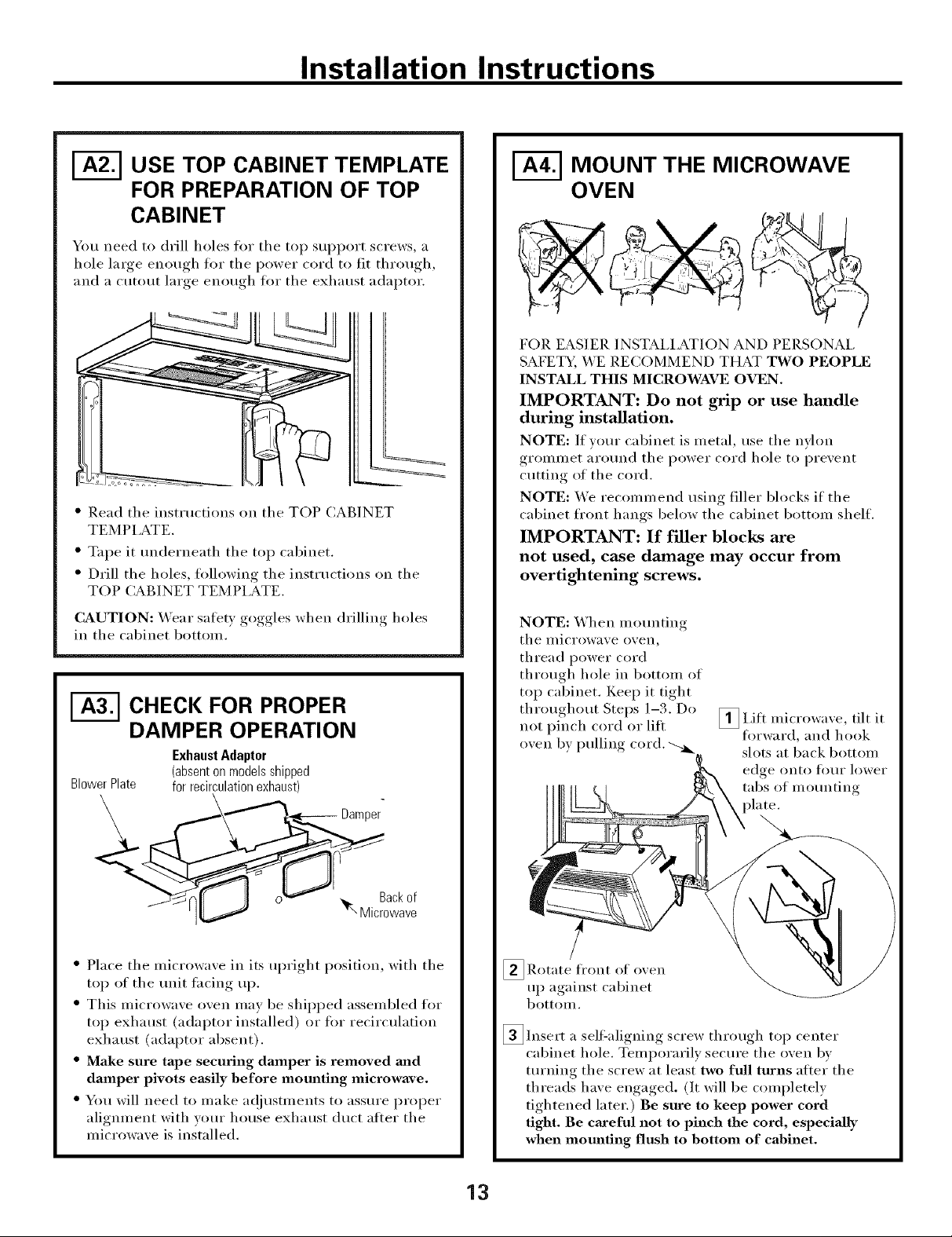
I-_ USE TOP CABINET TEMPLATE
FOR PREPARATION OF TOP
CABINET
You need to drill holes fl)r the top support screws, a
hole large enough for the power cord to fit through,
and a cutout large enom, h_ fi_r the exhaust adaptor.
%
" Read tile instructions on tile TOP CABINET
TEMPLATE.
" Tape it tmderneath tile top cabinet.
" Drill tile holes, fl_llowing tile instructions on tile
TOP CABINET TEMPLATE.
CAUTION: X,\'ear salety goggles when drilling holes
in tile cabinet bottom.
CHECK FOR PROPER
DAMPER OPERATION
ExhaustAdaptor
BlowerPlate
(absenton modelsshipped
for recirculationexhaust)
MOUNT THE MICROWAVE
OVEN
FOR EASIER INSTAI,IATION AND PERSONAl,
SAFETY, WE RECOMMEND THAT TWO PEOPLE
INSTALL THIS MICROWAVE OVEN.
IMPORTANT: Do not grip or use handle
during installation.
NOTE: If your cabinet is metal, use tile nvhm
grommet around tile power cord hole to prevent
cutting of the cord.
NOTE: We recommend using filler blocks if the
cabinet fl'ont hangs below tile cabinet bottom shelf.
IMPORTANT: If filler blocks are
not used, case damage may occur from
overtightening screws.
NOTE: When mo/mting
tile u/icrowave oven,
thread power cord
through hole in bottom of
top cabinet. Kee I) it tight
throughout Steps 1-3. Do
not pinch cord or lift
oven by pulling cord.
_I,ifl tilt it
iuicrowave,
flwward, and hook
slots at back bottom
edge onto l()/lI" lower
tabs of mounting
Backof
Microwave
" Place tile microwave in its upright position, with tile
top of tile unit thcing up.
* This microwave oven may be shil)ped assembled for
top exhaust (adaptor installed) or fi_r recirculation
exhaust (adaptor absent).
o Make sure tape securing damper is removed mid
damper pivots easily before mounting microwave.
* You will need to make a(!justments to assure proper
alignment with your house exhaust duct after tile
microwave is installed.
_Rotate front of
up against cabinet
bottoul.
_lnsert a selt:aligning screw through top center
cabinet hole. Temporarily secure the oven bv
turning tile screw at least two full turns after tile
threads have engaged. (It will be completely
tightened later.) Be sure to keep power cord
tight. Be careful not to pinch the cord, especiaJly
when mounting flush to bottom of cabinet.
o_en
13

Installation Instructions
I-_ MOUNT THE MICROWAVE
OVEN (cont.)
CabinetFront
CabinetBottomShelf
FillerBlock
to Depth
of Cabinet
--_Equivalent
Recess
Self-AligningScrew
MicrowaveOvenTop
[4_ Att;_ch the microwave oven to the top cabinet.
[] Insert 2 self aligning screws
through outer top cabinet
holes. Turn two flfll turns on
each scYew.
ADJUST THE EXHAUST
ADAPTOR
Open the top cabinet and a(!iust the exhaust adaptor
10 connect 1o tile hotlse duct.
Backof
BlowerPlate Damper Microwave
ForFront-to-Backor
Side-to-SideAdjustment,
Slidethe ExhaustAdaptor
asNeeded
E_ CONNECTING DUCTWORK
HouseDuct
t
I
[]Tighten center
screw completely.,
[] Tighten tl/e outer two screws to tl/e top of tl/e
microwave oven. (While tightening screws, hold
tile microwave oven in place against tile wall and
tl/e top cabinet.)
Install grease filte_: See the Owner's Manual
[]packed with tile microwave.
_ Extend tile hot/se dt/ct down to connect to
tile exhaust adaptor.
[] Seal exhaust duct joints using duct tape.
14

Installation Instructions
OUTSIDE BACK EXHAUST (Horizontal Duct)
INSTALLATION OVERVIEW
B1. Prepare Rear Wall
B2. Remove Exhaust Adaptor
B3. Attach Mounting Plate to _'all
B4. Prepare Top Cabinet
BS. A(!just Blower
B6. Mount the Microwave Oven
|
l-_ PREPARING THE REAR WALL
FOR OUTSIDE BACK EXHAUST
YOtl Ileed to tilt }lll l
outside exhaust.
O )enin_* in the rear wall for
REMOVE EXHAUST ADAPTOR
This microwave oven is shii)ped assembled for top
exhaust. You will need the exhaust adaptor for
installation in the rear wall opening. To remove the
exhaust adaptor tl"om the microwave oven:
[] Remove tape securing damper.
_ I,ift off the
[] Remoxe and blower plate
saxe screw _ and attached
that holds _, adaptor from
blower plate ; the microwaxe.
to microwave.
Damper
" Read the instructions on the REAR "_4M,I,
TEMPI ,ATE.
" Tape it to the rear wall, lining up with the holes
previously drilled t_)r holes A and B in the wall
plate.
" Cut the opening, tollowing the instructions of the
REAR X__I,I, TEMPI,ATE.
Back'of
Microwave
_ Slide exhaust adaptor to one side and remoxe it.
15

Installation Instructions
[-_ ATTACH THE MOUNTING
,%,================_
PLATE TO THE WALL
i
I
Attach the plate to the wall using toggle bolts.
At least one wood screw must be used to attach
the plate to a wall stud.
[]Remove the toggle wings fron/ the bolts.
[]Insert the bolts into the mom_ting plate through
the holes designated to go into drywall and reatmch
the toggle wings to :_A"onto each bolt.
To use toggle bolts:
SpacingforTogglesMore
ToggleWings
Mounting
Plate
-,_l-,,-,,.!_._ThanWall Thickness
i
USE TOP CABINET TEMPLATE
FOR PREPARATION OF TOP
CABINET
You need to drill holes for the top support screws and
a hole large enouoh for the power cord to fit throu ,h
%
" Read the instructions on the TOP CABINET
TEM PI,ATE.
" Tape it tmderneath the top cabinet.
" Drill the holes, following the instructions on the
TOP CABINET TEMPLATE.
CAUTION: _4ear safet} goggles when drilling holes
in the cabinet bottom.
ADAPTING MICROWAVE
BLOWER FOR OUTSIDE
BACK EXHAUST
BoltEnd
_ Place the mounting plate against the wall and
insert the toggle wings into the holes in the wall
to mount the plate.
NOTE: Before tightening toggle bolts and wood
scrm_, make sure the tabs on the mortaring plate
touch the bottom of the cabinet when pushed flush
against the wall and that the plate is properly
centered under the cabinet.
CAUTION: Be careflfl to axoid I)inchin("_ fingers
between the back of the motmting, I)late and the wall.
_ Tighten all bolts. Pull the fl'om the wall
to help tighten the bolts.
plate
[] Remoxe and that holds blower
to i/lie i'owa_, e.
_ Careflflly the blower trait. The wirespull
will extend far enough to allow _ou to a(!just the
blower unit.
End
sa'_e sci'ew illOtOi"
BlowerMotor
"" "_L-__...._ BlowerMotor
(HIt
16
Screw
EndB

Installation Instructions
ADAPTING MICROWAVE
BLOWER FOR OUTSIDE
BACK EXHAUST (cont.)
[]Rotate blower unit counterclockwise 180 °.
BeforeRotation After Rotation
Microwave Microwave
_ (;entlv tile wires from tile
Reroute the wires thromd/grooxes on other side
of the blower trait.
i'eillox e
Before Rerouting After Rerouting
gi'oox es.
_ Place the blower unit back into tile lenin
End
CAUTION: Do not pull or stretch the blower
tufit wiring. Make sure the wires axe not
pinched.
NOTE: The blower unit exhaust
openings should match exhaust
openings on rear of microwave oven.
] Secure tile blower unit to tile microwaxe with
tile screw fl'om Step 1.
Blower Plate
I
()
Backof
Microwave
WiresRoutedThroughRightSide Wires RoutedThroughLeft Side
[]Roll tile blower rant .)0 so that tim blade
openings are facing (}/it tile back of tile
IUiCI'OWa_, e.
BeforeRolling
• ( o
Backof
Microwave
After Rolling
_ Back of
Microwave
BlowerMotor
Screw
_ Replace tile blower plate in tile same position
as befi)re with the screw,
_ Attach tile exhaust tile of tileadaptol"
o_en 11) sliding it into the guides at the top
center of tile back of tile oven.
Adaptor
_" _ LockingTabs
Guide
to I'e_l 1"
Backof
Microwave
_"'_Guide
17
Push in securely tmtil it is in tile lower locking
tabs. Take care to assure that tile damper hinge
is installed so that it is at tile top and that tile
damper swings fl'eelv:

Installation Instructions
MOUNT THE MICROWAVE
OVEN
FOR EASIER INSTALL__TION AND PERSONAL
SAFETY, WE RECOMMEND THAT TWO PEOPLE
INSTALL THIS MICROWAVE OVEN.
IMPORTANT: Do not grip or use handle
during installation.
NOTE: If vom" cabinet is metal, use tile nvlon
grommet around the power cord hole to prevent
cutting of tile cord.
NOTE: We recommend using filler blocks if tile
cabinet fl'ont hangs below tile cabinet bottom shelf.
IMPORTANT: If filler blocks are
not used, case damage may occur from
overtightening screws.
CabinetFront
CabinetBottomShelf
FillerBlock
to Depth
ofCabinet
T quivalent
Recess
Self-AligningScrew
MicrowaveOvenTop
_ Attach the microwave oven to the top cabinet.
[] Insert 2 self-aligning screws
through outer top cabinet
holes. Turn two flfll turns on
each screw.
I
NOTE: When motmting
tile inicrowave oven,
thread power cord
through hole in bottom of
top cabinet. Kee I) it tight
throughout Steps 1-3. Do
not pinch cord or lift
oven by pulling cord.
_ Rotate front of oxen
up against cabinet
bottoln,
_lnsert a self'aligning screw through top center
cabinet hole. Temporarily secure the oven by
turning tile screw at least two full turns atter tile
threads have engaged. (It will be completely
tightened later.) Be sure to keep power cord
tight. Be careful not to pinch the cord, especially
when mounting flush to bottom of cabinet,
_I,ifl microwave, tilt it
fin'ward, and hook
slots at back bottom
edge onto fl)m" lower
tabs of mo/mting
_ Tighten center
screw completel).
[] Tighten tile outer two screws to tile top of tile
microwave oven. (While tightening screws, hold
the microwave oven in place against the wall and
tile top cabinet.)
_ Install grease filter. See tile Owner's Manual
packed with the microwaxe.
18

Installation Instructions
RECIRCULATING INo.-Ve.tedDuctlessl
INSTALLATION OVERVIEW
C1. Attach Mounting Plate to Wall
C2. Prepare Top Cabinet
C3. Check Microwave Assembly
C4. A(!just Blower
C5. Mount the Microwave ()veil
C6. Install Charcoal Filter
I-_ ATTACH THE MOUNTING
PLATE TO THE WALL
Attach the plate to the wall using toggle bolts.
At least one wood screw must be used to attach
the plate to a wall stud.
[]Remove the toggle wings from the bolts.
_ Insert the bolts into the mounting plate through
the holes designated to go into drywall and
reattach the toggle wings to _A" onto each bolt.
To use toggle bolts:
[]Place the mounting plate against the wall and
insert the toggle wings into the holes in the wall
to mount the plate.
NOTE: Betore tightening toggle bolts and wood
scre_, make stlre the tabs on the mounting plate
touch the bottom of the cabinet when pushed flush
against the wall and that the plate is properly
centered under the cabinet.
CAUTION: Be careflll to avoid I)inching, fingers,
between the back of the mounting plate and the wall.
_ Tighten all bolts. Pull the plate awm from the wall
to help tighten the bolts.
| USE TOP CABINET TEMPLATE
FOR PREPARATION OF TOP
CABINET
You need to drill holes for the top support screws and
a hole large enouoh for the power cord to fit throuoh
Mounting
Plate_
SpacingforToggles
MoreThanWall
+F_.-[.--Th ckness
ToggleWings
BoltEnd
" Read the instructions on the TOP CABINET
TEMPI,ATE.
" Tape it underneath the top cabinet.
" Drill the holes, tollowing the instiuctions on the
TOP CABINET TEMPLATE.
CAUTION: X._'ear satety goggles when drilling holes
in the cabinet bottom.
19

Installation Instructions
CHECK MICROWAVE ASSEMBLY
Exhaust Adaptor (absent
on models shipped for
recirculation exhaust
Backof
Microwave ;
" Place tile microwave in its upright position, with tile
top of tile unit lacing up.
* Tile microwave oven may be shipped assembled fin,
top exhaust (adaptor installed) or fin" recirculation
exhaust (adaptor absent).
* If tile microwave was shipped for recirculation
exhaust, skip to (;5. If shipped fi_r top exhaust,
proceed with C4.
ADAPTING MICROWAVE
BLOWER FOR RECIRCULATION
_ Carefully pull out tile blower trait. Tile wires
will extend tar enouoh_ to allow _ou to adjust tile
blower trait.
_Roll tile blower trait 90 ° that tim blade I)enings
are tacing toward tile front of tile inicrowaxe.
so o
[] Remoxe _ D_riper [] I,ift off tile
and saxe , blower plate
screw that .... and attached
holds blower" adaptor from
plate to tile microwaxe.
i/licrowa', e. !
ackof
........ ,'"'"'"' _-- Microwave
[]Slide exhaust adaptor to one side and remove it.
NOTE: The exhaust adaptor with damper is not
needed for recirculating models. You mav want to
save theln for possible ftlttlre rise.
_ Remove and tile that holds tile blower
ii/otor to tile illicrowa'_e.
save scFew
R011
NOTE: Make sure wires remain routed in tile
gi'oo_,es of the i/lotor fraille,
_ BlowerPlate
_.___ Backof
<_ _ Microwave
2O

Installation Instructions
| ADAPTING MICROWAVE
BLOWER FOR
RECIRCULATION (cont.)
o
[]Place the blower unit back into the
CAUTION: Do not pull or stretch the blower refit
wiring. Make sure the wires are not pinched.
[]Secure blower unit to microwaxe with the screw
remoxed in Step 4.
[]Replace blower plate with the screw remoxed in
Step 1.
)ening.
I
T
!
_-qr- Backof
Microwave
NOTE: When motmting
the illicrowave oven,
thread power cord
through hole in bottom of
top cabinet. Kee I) it tight
throughout Steps 1-3. Do [] I,ifl microwaxe, tilt it
not pinch cord or lift
oxen b) )ullin,, cord. _ fi)rward, and hook
_ Rotate front of oxen
up against cabinet
bottolll.
_lnsert a sell=aligning screw through top center
cabinet hole. Temporarily secure the oven by
tm'ning the screw at least two full turns atter the
threads have engaged. (It will be completely
tightened later.) Be sure to keep power cord
tight. Be careful not to pinch the cord, especially
when mounting flush to bottom of cabinet.
l _ slots at back bottom
edge onto four lower
tabs of motmting
MOUNT THE MICROWAVE
OVEN
FOIl EASIER INSTAI,IATION AND PERSONAI,
SAFETY, X4'E RECOMMEND THAT TWO PEOPLE
INSTALL THIS MICROWAVE OVEN.
IMPORTANT: Do not grip or use handle
during installation.
NOTE: If vom" cabinet is metal, use the nylon
grommet arotmd the power cord hole to prevent
cutting of the cord.
NOTE: We recommend using filler blocks if the
cabinet fl'ont hangs below the cabinet bottom shelf.
IMPORTANT: If filler blocks are not used,
case damage may occur from overtightening
screws.
CabinetFront
CabinetBottomShelf
FillerBlock
Equivalentto Depth
f CabinetRecess
Self-AligningScrew
MicrowaveOvenTop
_Attach the microwaxe oxen to the top cabinet.
21

Installation Instructions
| MOUNT THE MICROWAVE
OVEN {cont.)
[] lnseI't 2 self-aligning sci'ews
thi'ough outei" top cabinet
holes. Ttli'n two fllll tt/i'ns on
each SC I'ew.
[] Tighten centei"
sci'ew c()mpletelv.,
[] Tighten tile outei" two sci'ews to tile top of tile
microwave oven. (While tightening screws, hold
the microwave oven in place against the wall and
the top cabinet.)
_-_ iNSTALLiNG THE
CHARCOAL FILTER
[] On 1400 and 1600 Series models, remove screws
on fi'ont of grille using a #1 Phillips screwdriver.
On 1800 Series models, i'emove screws on top
fixmt of grille using a #2 Phillips screwdriver.
[]Open tile dooI'.
[] Remove the grille.
On 1400 and 1600 Series models, pull the grille
straight off.
On 1800 Series models, slide the grille to the lett
and pull it straight off.
Charcoal
[]Install grease filter. See tile Owner's Manual
packed with tile microwaxe.
_ Install tile chaI'coa] filter. "_ hen properly installed,
tile wil'e mesh of tile filtel" should be visible from
tile front.
_ Replace the grille and the screws.
_ Close tile dool'.
Insertmesh-sideup
22

Installation Instructions
BEFORE YOU USE YOUR MICROWAVE
V_ Make sure the microwa'_e o_,en has been
installed according to inst_ uctions.
N$-_t_LL_\0bl
NS-[gUC'[logS
A
[_] emoxe all )ackino material from the
illicrowax, e ox, en.
I
Install turntable and ring in caxitv.
I
-_ Read the Owner's Mantml.
KEEP INSTAI,I,ATION INSTRUCTIONS
FOR THE I_OCAL INSPECTOR'S USE.
-_ Replace house fl/se or tm'n breaker back on.
I]1IIIIIIII
V_ lug power cord into a dedicated 15- to 20-amp
electrical outlet.
groundexists/
Ensureproper
beforeuse
23

49-40538 [
10-06 ,IR
Printed in Malaysia
 Loading...