

GE Appliances Disposall GFC320, Disposall GFC530, Disposall GFC520, Disposall GFC1020, Disposall GFB760 Owner's Manual And Installation Instructions
...Page 1
GEAppliances.com
©
©
Safety Instructions
Connecting Electricity ..... 2, 3
Safety Precautions .......... 2
Installation Instructions
Attaching the
Discharge Elbow ............ 6
Components and Installation
of Sink Flange ............. 5
Connecting Disposer
to Sink Flange .............. 7
Dimensions/Typical
Installations ................ 8
Dishwasher Connection ...... 6
Operating Instructions
Batch Feed Models .......... 9
Care and Maintenance ...... 10
Continuous Feed Models ..... 9
Troubleshooting Tips
Before You Call for Ser_,Jce .... 11
Model Line Series
(;FC320
(;FC520
(;FC530
CFC720
CFC1020
(;FB760
Consumer Support
Warranty ................ 12
Write the model and serial
numbers foryour disposall here:
Model #
Serial #
You can find them on a label on
the bottom of the dispose_.
165D4700P267 49-5941 07-02JR
Page 2
IMPORTANT SAFETYINSTRUCTIONS.
READALLINSTRUCTIONS BEFOREUSING.
INSTRUCTIONSPERTAININGTOA RISKOFFIRE,ELECTRICSHOCKOR
INJURY TOPERSONS
A WARNING'!
When using electrical appfiances, basic safety precautions should be followed, including the following:
SAFETYPRECAUTIONS
_iUse this appliance only for its intended purpose
as described in this Owner's Manual.
{{_iReadall the instructions before using the
appliance.
{{_iToreduce the risk of i_jury, close supervision
is required when an appliance is used near
children.
{{_iDonot put fingers or hands into a waste
disposeL
{{_iTurnthe power switch (normally a wall switch)
to the off position before attempting to clear
a jam or remove an object flom the disposeL
_When attempting to loosen a jam in a waste
disposm; use a long wooden object such as
a wooden spoon or the wooden handle of
a broom or mop.
_When attempting to remove objects flom
a waste disposer, only use long-handled,
non-magnetic tools or utensils, since the
disposer may be actuated magnetically.
_To reduce the risk of ii_jury by materials that may
be expelled by a waste dispose_; do not put the
following into a disposer:
a) Clam or oyster shells.
b) Caustic drain cleaners or similar products.
c) Glass, china or plastic.
d) I,arge whole bones.
e) Metal, such as bottle caps, tin cans, utensils
or aluminum foil.
f) Hot grease or other hot liquids.
g) Whole corn husks.
_When not operating a disposer, leave the drain
stopper in place to reduce the risk of objects
falling into the disposer.
Forpropergroundinginstructions,see the
ELECTRICALCONNECTIONportionof thismanual
WARNING!
HOWTOCONNECTELECTRICITY
If you are not famifiar with electrical power and procedures, call a qualified electrician.
DANGER:Improperconnectionof the equipment-
groundingconductor can result ina risk of electric shock.Check
with a qualified electrician or serviceman if you are in doubt as
to whether the appliance is properly grounded.Do not modify
theplug provided with the applianceif it wit not fit the outlet,
havea proper outlet installed by a qualified electrician.
2
For Models Equipped with a Grounded Cord:
GROUNDINGINSTRUCTIONS:This appliance must
be grounded. In the event of a malfunction or
breakdown, grounding provides a path of least
resistance for electric current to reduce tim risk of
electric shock. This appliance is equipped with a
cord having an equipment-grounding conductor
and a grounding plug. The plug must be plugged
into an appropriate oudet that is properly installed
and grounded in accordance with all local codes
and ordinances. Most houses have electrical outlets
under tim sink that are half-hot. Tiffs means one
outlet is controlled by the wall switch, while the
other is always hot. The batch-feed or "TC" model
connects to the hot side, while the continuous feed
model connects to tim switch side.
Page 3
WARNING!
HOWTOCONNECTELECTRICITY(cont.)
If you are not familiar with electrical power and procedures, call a quafified electrician.
GEAppliances.com
The power cord and/or connections must comply
with tile National Electrical Code, Section 422
and/or local codes and ordinances.
For Models Not Equipped with a Cord:
Ifyour disposer does not come equipped with a cord,
you can connect it in two ways:
1. Attach a power cord, IIlinilIltlIIl 18" ill length and
not to exceed 36" in length. (;E Kit #PM3X115
provides the parts needed to make this connection.
or
2. Wire tile disposer directl_ into tile house current.
GErecommends that a qualified electrician make
this connection.
ToAttach a Power Cord:
GROUNDINGINSTRUCTIONS:This appliance must be
grounded. In tile event of malflmcfion or breakdown,
grounding provides a path of least resistance for
electric current to reduce tile risk of electric shock.
Tile power cord (to be insmUed) must have an
equipment-grounding conductor and a grounding
plug. Tile plug must be plugged into an appropriam
outlet that is properly instaUed and grounded in
accordance with aU local codes and ordinances.
In the absence of local codes and/or ordinances,
tile outlet must comply with NEC requirements.
DANGER:Improperconnection of the equipment-
groundingconductorcanresultin a riskof electricshock.
Checkwith a qualifiedelectricianorservicemanif youare
indoubtas to whethertheapplianceisproperlygrounded.
NOTE:Disconnectelectricpowertodisposercircuitbefore
installation.Turnthe circuitbreakerto the OFFpositionor
removethefuse.
A. Connect the disposer to 110-120 Volt, 60 Hz AC
current only.
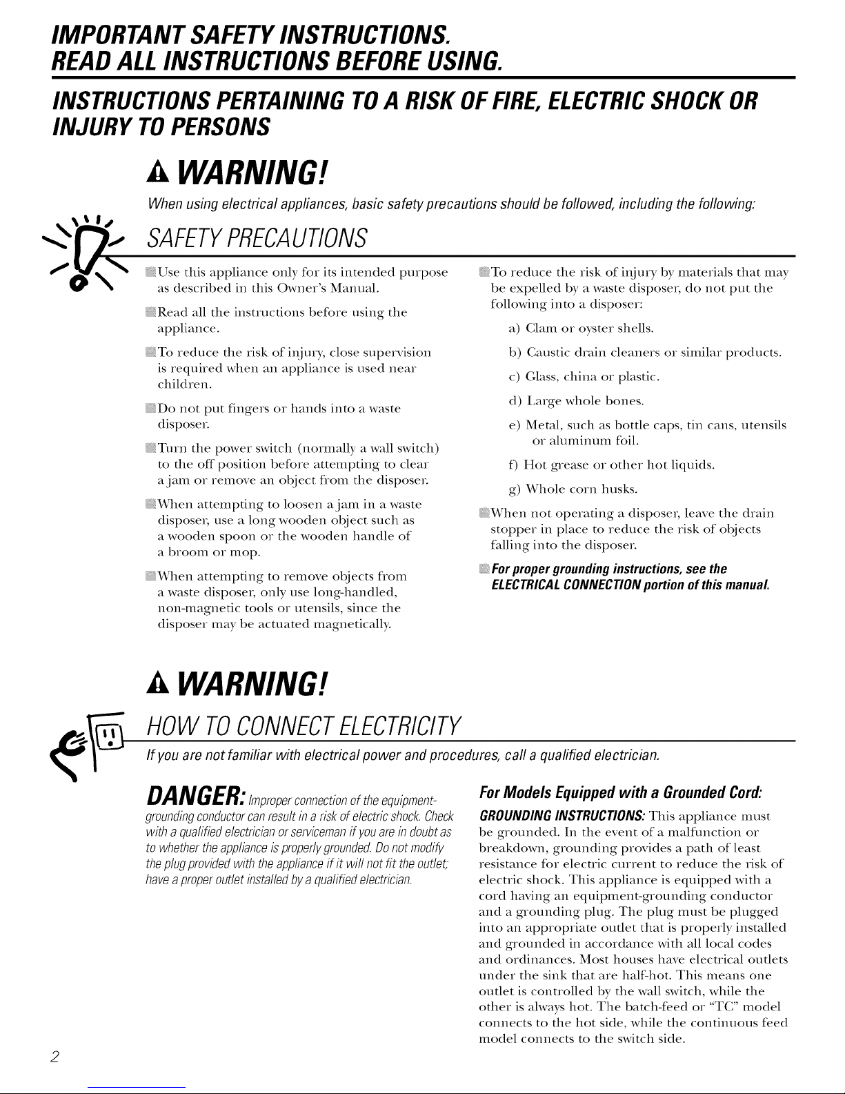
B. If a plug-in cord is used, use a three-prong
plug. Ground wire should be attached to tile
ground screw in the bottom of the disposer
(end bell).
Traceleadconnectedtothis
bladeandattachthat lead Ribbed
to white wire ondisposer. Side
1_ Wh_""enviewingfaceofelectricalplug
withgroundingpinattop,thelargerleftblade
isconnectedtotheidentifiedwire.
C. Use a cable clamp strain relief
connector where power cord
enters the disposer.
ToWire YourDisposerDirectlyinto
theHouseCurrent:
Nut
GErecommendsthata qualified
electricianmake this connection.
GROUNDING INSTRUCTIONS: This appliance must be
connected to a grounded, metal, permanent wiring
system; or an equipment-grounding conductor must
be run with the circuit conductors and connected
to the eqtdpment-grounding terminal or lead on
the appliance.
DANGER:Improper connection of the equipment-
grounding conductor can result ina risk of electric shock.
Checkwith a qualified electrician or serviceman if you are
in doubt as to whether the appliance is properly grounded.
A. If you use BX cable:
1. Install the cable connector in the hole.
2. Connect white wire to white lead of disposer.
3. Connect black wire.
4. Connect bare ground wire.
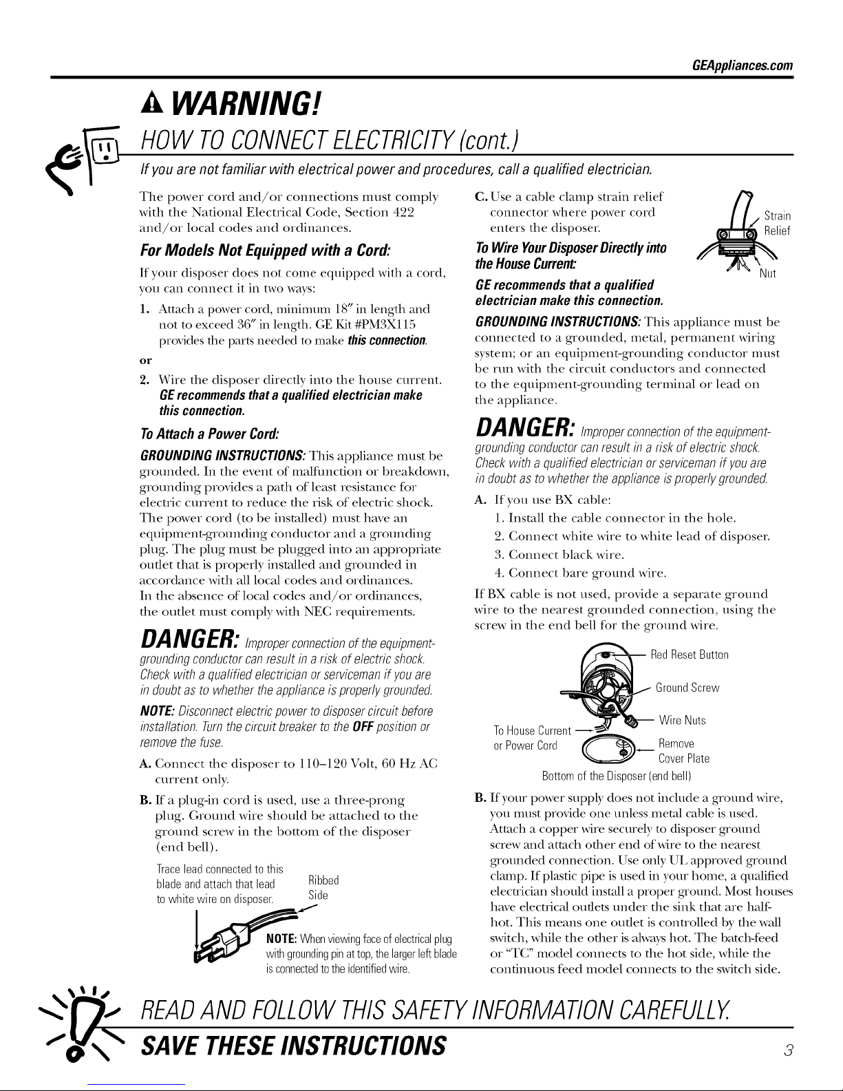
If BX cable is not used, provide a separate ground
wire to the nearest grounded connection, using the
screw in the end bell for the ground wire.
RedResetButton
Ground Screw
ToHouseCurrent
or PowerCord _----_"_ Remove
Bottomof the Disposer(endbell)
Bo
If your power suppb, does not include a ground wire,
you umst provide one unless metal cable is used.
Attach a copper wire securely to disposer ground
screw and attach other end of wire to the nearest
gxounded connection. Use only UL approved ground
clmnp. If plastic pipe is used in your h ore e, a qualified
electrician should install a proper ground. Most houses
have electrical oudets under the sink that are half-
hot. This means one oudet is conuolled by the wall
switch, while tile other is always hot. Tile batch-feed
or "TC" model connects to the hot side, while the
continuous feed model connects m the switch side.
Wire Nuts
CoverPlate
Strain
Relief
READANDFOLLOWTHISSAFETYINFORMATIONCAREFULLY.
SAVETHESEINSTRUCTIONS
3
Page 4
Installation
Disposer
Instructions
I ff you have questions, call 800.GE.CARES(800.432.2737)or Visit our Website at: GEAppliances.com I
BEFORE YOU BEGIN
Read these instructions completely and carefully.
• IMPORTANT - S_,,,ethese
instructions for local inspector's use.
• IMPORTANT - Obse_,,e_,ll
governing codes and ordinances.
• Note to Installer - Be sure to leave these
instructions with the Gonsumer.
• Note to Consumer - Keep these instructions
for fi_ture reference.
• Sldll level - Installation of tlfis appliance requires
basic mechanical skills.
• Completion time - 1 hour
• Proper installation is the responsibility of the
insudleL
• Product failure due to improper installation is not
covered under the _rananty.
PREPARATION
1. Disconnect electrical power supply to disposeL
2. Remove old disposer or sink flange assembly.
3. Inspect drain line. If it is heavily coated with hardened
gnease and accumulations, rout out with a plumber's
snake.
4. Remove old sealing mateviMs and gaskefing flom sink
opening, both top and bottom.
NOTE: Top and bottom of sink surfaces must be flee
of any materials to prevent leaks.
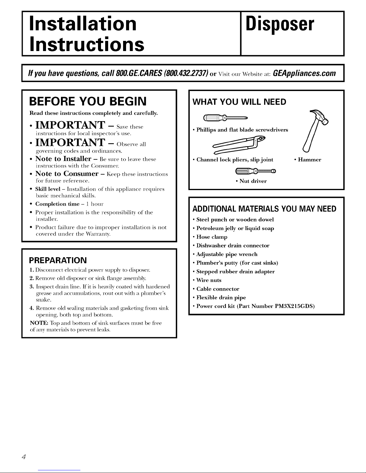
WHAT YOU WILL NEED
• Phillips and flat blade screwdrivers
• Channel lock pliers, slip joint
• Nut driver
• Hammer
ADDITIONAL MATERIALSYOU MAY NEED
• Steel punch or wooden dowel
• Petroleum jelly or liquid soap
• Hose clamp
• Dishwasher drain connector
• Adjustable pipe wrench
• Plumber's putty (for cast sinks)
• Stepped rubber drain adapter
• Wire nuts
• Cable connector
• Flexible drain pipe
• Power cord kit (Part Number PM3X215GDS)
4
Page 5

Installation Instructions
El COMPONENTSANDINSTALLATION
COMPONENTS
..............*Stopper
*Removable
_lashGuard
/Sink Flange
RubberSink
FlangeGasket
SinkFlange-
Assembly
FiberGasket
SupportRing
(NoteArrows
IndicatingUp)
ountRing
JTightening Ears
._Cushi0n Mount
Groove_ Dishwasher
Disposer --
*Not used with batch feed model
Hopper _ "*"/Disa-_WchargeGasketlnlet
Elbow
EndBell _ Flange Discharge
(Electrical Elbow
Connections) RatingLabel
inThisArea
"rews
INSTALLATION OF SINK FLANGE
(Read completely before starting.)
CorrectlyInstalled Sink Flange
SinkFlange .,,,, RubberGasket
FiberGasket_
BottomBeadof
CushionMount _ _ _1-_ SinkFlange
;L // 2; _,
OpenAreaNoObstruction MountRingshouldbefree
Groove
Bottom
(shownfor properorientation)
(JJ_ SupportRing
to moveupanddown
_ Sink
CushionMount
NOTE: Pay close attention to the order of the sink
flange parts, as they have been correctly assembled
by the factory.
A. Disassemble the sink flange assembly flom the
disposer by turning the mount ring to the left
(clockwise) and removing it.
B. Raise the mount ring toward the top of the sink
flange. Remove the cushion mount and the mount
ring. You may want to practice installing the
cushion mount at this point before you are under
the sink.
C. Unscrew the support ring flom the sink flange and
remove the tiber gasket. You are now left with the
sink flange and the rubber gasket.
D. The rubber gasket is used instead of plumbers
putty with stainless steel sinks.
E. If no putty is used, insert the sink flange through
the rubber gasket into the sink opening. Do not
turn the flange once it is seated.
E If you use putty instead of the gasket, form a ring
around the underside of the sink flange. Insert the
flange into the sink opening, press down hard to
squeeze out excess putty. From under the sink,
trim off excess putty flush with the bottom edge
of the sink opening. Use putty sparingly on cast
iron sinks.
G.From underneath the sink,
slip the tiber gasket onto the
exposed sink flange. With
arrows pointing up, screw the
support ring onto the sink
flange and hand tighten until
the sink flange will not move. At
Hand-tightensink
flange
this point you may want to insert the stopper
in the sink and fill with water to check the sink
flange seal and insure there are no leaks.
H.Place the mount ring over
the sink flange and hold in
place while installing the
cushion mount (large side
down). Make sure the
groove on the inside of the
cushion mount fits over the
lip on the sink flange, CushionMountDetail
similar to putting the lid Top
on a plastic container.
Run your fingers
around the entire
cushion mount with
slight pressure. Do not press too hard. When the
cushion mount is properly seated, the mount ring
can be pulled downward over the cushion mount
and will be fiee to turn.
5
Page 6
Installation Instructions
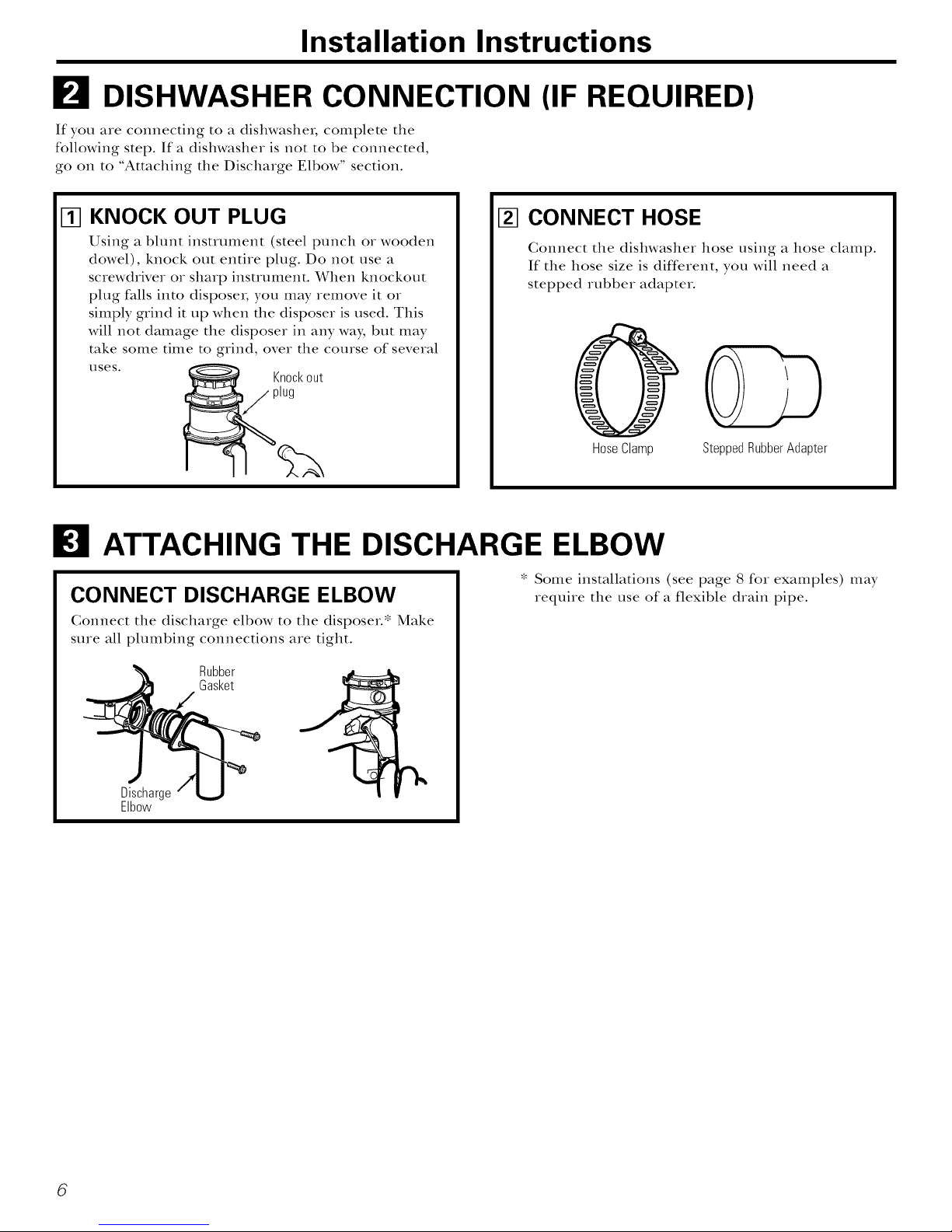
I_ DISHWASHER CONNECTION (IF REQUIRED)
If you are connecting to a dishwasher, complete the
following step. If a dishwasher is not to be connected,
go on to "Attaching the Discharge Elbow" section.
KNOCK OUT PLUG
%
Using a blunt instrument (steel punch or wooden
dowel), knock out entire plug. Do not use a
screwdrNer or sharp instrument. When knockout
plug falls into disposer, you may remove it or
simply grind it up when the disposer is used. This
will not damage the disposer in any way, but may
take some time to grind, over the course of several
uses.
Knockout
plug
I_ CONNECT HOSE
(;onnect the dishwasher hose using a hose clamp.
If the hose size is different, you will need a
stepped rubber adapter.
Hose Clamp Stepped Rubber Adapter
I_ ATTACHING THE DISCHARGE ELBOW
CONNECT DISCHARGE ELBOW
Gonnect the discharge elbow to the disposer.* Make
sure all plumbing connections are tight.
Rubber
Gasket
rh.
Discharge
Elbow
* Some installations (see page 8 for examples) may
require the use of a flexible drain pipe.
6
Page 7
Installation Instructions
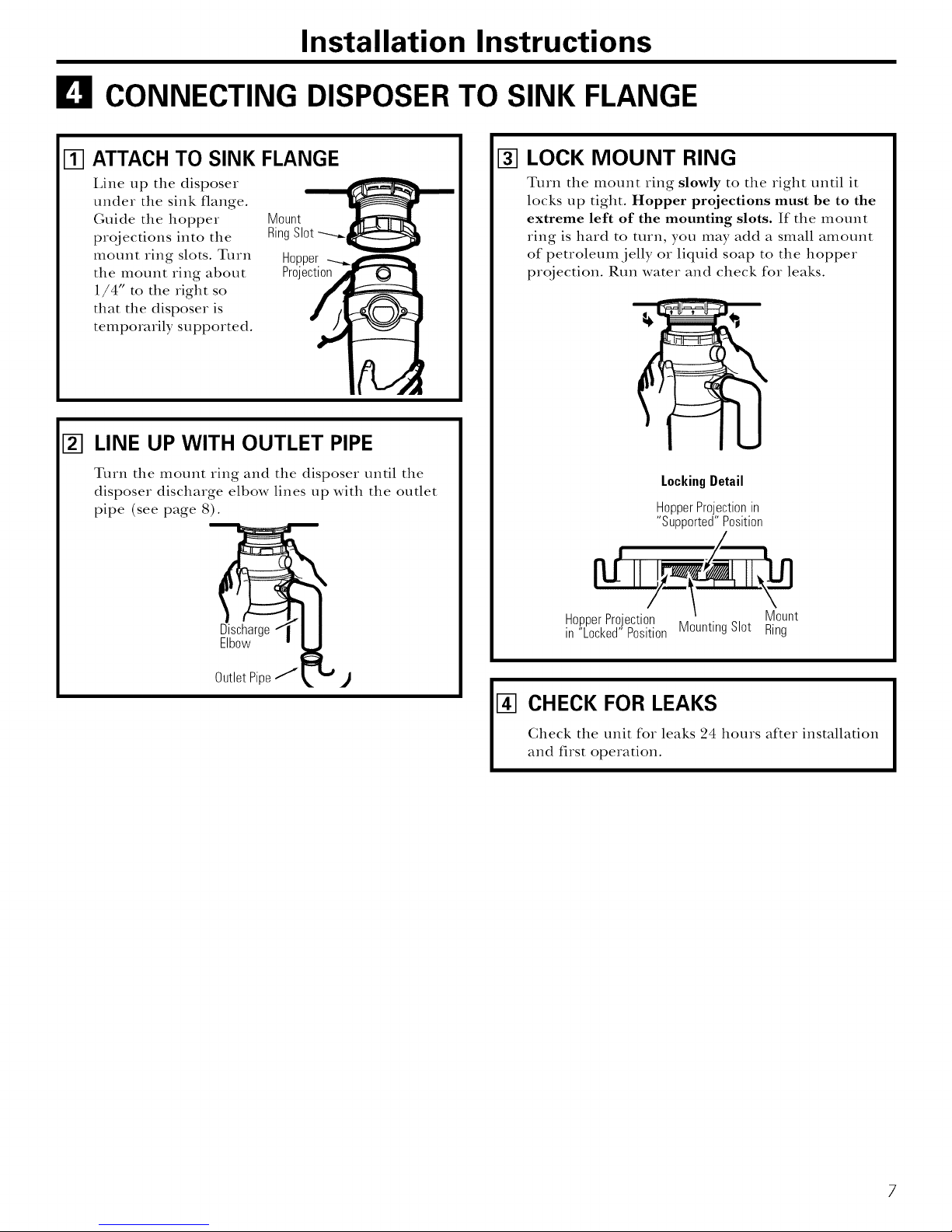
CONNECTING DISPOSERTO SINK FLANGE
ATTACH TO SINK FLANGE
%
Line up the disposer
under the sink flange.
Guide the hopper Mount
prqjections into the RingSlot
mount ring slots. Turn Hopper
tlle mount ring about Projection
1/4" to the right so
that tile disposer is
temporarily supported.
[] LINE UP WITH OUTLET PIPE
Turn tile mount ring and tlle disposer until tlle
disposer discharge elbow lines up with tile outlet
pipe (see page 8).
I_ LOCK MOUNT RING
Turn tlle mount ring slowly to tile right until it
locks up tight. Hopper projections must be to the
extreme left of the mounting slots. If tlle mount
ring is hard to turn, you may add a small amount
of petroleum jelly or liquid soap to the hopper
projection. Run water and check for leaks.
LockingDetail
HopperProjectionin
"Supported"Position
Discharge
Elbow
OutletPipe/1
HopperProjection Mount
in "Locked"Position MountingSlot Ring
CHECK FOR LEAKS
Gheck tile unit for leaks 24 hours after installation
[]
and first operation.
7
Page 8
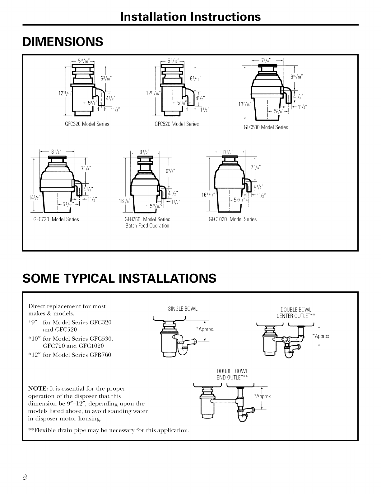
DIMENSIONS
Installation Instructions
41/2"
GFC320ModelSeries
872"
GFC720ModelSeries
I_ 11/2"
GFC520ModelSeries
............8W'
----- 93/¢
GFB760ModelSeries
BatchFeedOperation
I-- 11/2"
SOME TYPICAL INSTALLATIONS
137/1G"
!
GFC530ModelSeries
8W'
71/4"
F 5% _i
GFCI020ModelSeries
11/2"
Direct replacement for most
makes & models.
"9" for Model Series GFC320
and GFC520
"10" for Model Series GFC530,
GFC720 and GFC1020
"12" for Model Series GFB760
NOTE: It is essenual for the proper
operation of the disposer that this
dimension be 9"-12", depending upon the
models listed above, to avoid standing water
in disposer motor housing.
**Flexible drain pipe may be necessary for this application.
8
SINGLEBOWL
'Approx.
DOUBLEBOWL
ENDOUTLET**
._ 'Approx.
DOUBLEBOWL
CENTEROUTLET**
tl
Page 9

Operatinginstructions. GEAppliances.com
This disposer uses anti-jam swivel impellers that make a clicking sound as they swing into place.
This indicates normal operation.
ContinuousFeedModels
Ova
A. Remove the sink stopper and turn on
a medium flow of cold wateL
B. Turn the switch to ON.
C. Scrape in food waste. To speed up food
waste disposal, cut or break up large
bones, rinds and cobs. I,arge bones
and fibrous husks require considerable
grinding time and are more easily
thrown away with other trash. Do not
be alarmed that the disposer slows down
while grinding. The disposer is actually
increasing torque (grinding power) and
is operating under normal conditions.
BatchFeedModels
A. Remove the sink stopper and mrn on
a medium flow of cold wateL
B°
Scrape in food waste.
C.
Insert the stopper to start the disposer.
One of the two small slots in the stopper
base must line up with the switch phmger
inside the neck of the disposeL
NOTE:Theovalshapedhandlealignswith the
2 smallslotsin the stopper
D. Before turning the disposer off, let
the water and the disposer run for
approximately 25 seconds after
shredding stops. This assures that
all waste is thoroughly flushed through
the uap and drain.
E. Do not use hot water while running the
disposeL (;old water will keep food waste
and fats solid so they can be flushed
down the drain.
Large _um
Srr
Pushdownfirmlytostart.
D°
Run the disposer for 25 seconds after
shredding stops. Tiffs assures that all
waste is tlloroughly flushed through
the trap and drain.
Lift the stopper toshut the disposeroff.
E°
To fill the sink, insert the stopper so that
the largest slot lines up with the switch
plungeL The stopper can now be pushed
down to seal the sink without starting the
disposeL When the medium-sized slot in
the stopper base is lined up with the
switch phmger, water can drain, but
tableware, etc., cannot be accidentally
dropped into the disposeL
9
Page 10

Operatinginstructions.
HelpfulHints
A. Be sure the disposer is empty before using
the dishwasher so it can drain properly.
B, You may want to leave the stopper in the
drain when not in use to prevent utensils
and foreign objects flom falling into the
disposeL
C°
The disposer is ruggedly built to give you
years and years of trouble-flee service.
It will handle all normal food wastes--
BUT it will not grind and dispose such
items as tin cans, bottles and bottle caps,
glass, china, leather, cloth, crocke_y,
rubbe_; suing, feathers, or clam or oyster
shells. These are waste materials and
belong in the uash can or uash
compactoL
Careandmaintenance.
D. TO SPEED UP FOOD WASTE
DISPOSAl .... Cut or break up large bones,
melon rinds, grapefruit skins and corn
cobs. Items such as large bones, fibrous
husks like lima bean pods and corn husks
require considerable cutting time. For this
reason, you may prefer to place them in
the trash can or trash compactoL
THEMOTOR IS PERMANENTLY LUBRICATEDFOR LIFE.DO NOT ATTEMPT TO LUBRICATE
YOURDISPOSER. The disposer is self cleaning and scours itself with each use.
_NEVER put lye or chemical cleaners into the
disposer, as they cause serious corrosion of
metal parts.
_Your disposei, except for the Batch Feed
model, is equipped with a removable splash
guard for ease of cleaning or replacement.
Remove the splash guard by pulling it out
flom tim top. To replace, insert into the
sink flange and push down until it is
properly seated.
_Ifan odor develops, run orange or lemon
rinds through the disposer. A dozen ice
cubes sprinkled with a little household
scouring powder will also work.
10
Page 11

Before you call for service... GEAppliances.com
Troubleshooting Tips
Save time and money! Review the chart on this page first
and you may not need to call for service.
SAFETY NOTE: Before investigating, you must disconnect the power supply.
WARNING!
Before resetting, disconnect the power supply-please see SAFETY NOTEabove. The overload control prevents the motor
from operating should overloading occur. This feature protects your house wiring and your disposer. When overloaded,
the motor will stop automatically.
Possible Causes
Loud noises (other than Silverware, bottle cap or other
those during grinding of foreign object has fallen into
bones and fruit pits)the disposer.
Disposerdoesnot start
Reset button has been tripped.
Reset
.Button
No.
Turntable cannot rotate.
What ToDo
* Remove the splash guard '!: and remove the object with
long-handled tongs. Replace the splash guard.*
• With the splash guard* removed, check to see if the
turntable will move fieely using a broom handle. If the
turntable moves fieely, replace the splash guard* and check
the reset button to see if it has been tripped. The reset
button is red and located opposite the discharge elbow,
near the bottom of the disposeL Push the button in until
it clicks and remains depressed. If the reset button has not
been tripped, check for a shorted or broken whe connecting
to the disposeL Check the electrical power switch, fllse box
or circuit breakeL If wiring and electrical components are
intact, the unit may have internal problems that require
service or replacement.
• If the turntable does not mrn fleely, check for an object
lodged between the turntable and the grind ring. Dislodge
the object by moving the turntable with a broom handle.
Then remove the object.
If no foreign object is present, there may be internal
problems.
Disposerleaks If the leak is at the top, it may be
caused by:
1. Improper seating of sink flange
(gasket choice, putty or tightening).
2. Support ring not tightened properly.
3. Defective cushion mount.
If the leak is at the discharge elbow,
leak may be caused by improper
tightening of elbow flange screws.
*Batch Feed does not include splash guard.
Remove
SplashGuard
11
Page 12

Disposer Warranty.
Aft warranty service provided by our Factory Service Centers, or
an authorized Customer Care®technician. To schedule service,
on-line, 24 hours a day, visit us at GEAppliances.com, or carl
800.GE.CARES (800.432.2737).
OneYear
From the date of the
origina!purchase
AdditionalOneYear
From the date of the
origina!purchase
AdditionalTwo Years
From the date of the
original purchase
AdditionalFourYears
From the date of the
origina!purchase
Staple your receipt here.
Proof of the original purchase
date is needed to obtain service
under the warranty.
GE Will Replace:
The entire disposer if there is a defect in materials or workmanship reladng to functional parts
only (appearance parts are excluded). During this full one-year warranty, GE will also provide,
free of charge, all labor charges related to replacing the original disposer along with the
replacement disposer within the first yeaL
Model I,ine Series GFC520: If there is a defect in materials or workmanship relating to
flmcfional parts only (appearance parts are excluded). During this one year extendedlimited
warranty period, you will be responsible for all installation charges relating to the replacement
disposeL
Model I,ine Series GFC530: If there is a defect in materials or workmanship reladng to
fimcdonal parts only (appearance parts are excluded). During this two year extended limited
warranty period, you will be responsible for all installation charges relating to the replacement
disposeL
Model I,ine Series GFC720: If there is a defect in materials or workmanship reladng to
flmcdonal parts only (appearance parts are excluded). During this four year extended limited
warranty period, you will be responsible for all installation charges reladng to the replacement
disposeL
AdditionalSix Years
From the date ofthe
origina! purchase
Service trips to your home to teach you how to use
the product.
Improper installation.
Failure of the product if it is abused, misused, or
used for other than the intended purpose or used
commercially.
Replacement of house fuses or resetting of
circuit breakers.
Model I,ine Series GFCI020: If there is a defect in materiMs or workmanship reladng to flmcfionM
parts only (appearance parts are excluded). During this six year extended limited warranty
period, you will be responsible for all installation cha_ges relating to the replacement disposer.
Damage to the product caused by accident, fire, floods
or acts of God.
Incidental or consequential damage caused by possible
defects with this appliance.
This warranty is extended to the original purchaser and any succeeding owner for products purchased for home use
within the USA. In Alaska, the warranty excludes the cost of shipping or service calls to your home.
Some states do not allow the exclusion or limitation of incidental or consequential damages. This warranty gives you
specific legal rights, and you may also have other rights which vary from state to state. Toknow what your legal rights
are, consult your local or state consumer affairs office or your state's Attorney General
Warrantor: General Electric Company. Louisville, KY 40225
12 Printed in the United States
Page 13

©
GEAppliances.com
Informaci6n de seguridad
C6mo conectar
la corriente el_ctrica ....... 2, 3
Precauciones de seguridad .... 2
Instrucciones para la instalaci6n
C6mo conectar el codo
de descarga ................ 6
C6mo conectar el triturador
a la brida del lavaplatos ....... 7
Componentes e instalaci6n
para la brida del lavaplatos .... 5
Conexi6n hacia la lavadora
de platos .................. 6
Dimensiones/
Instalaciones t/picas .......... 8
Instrucciones de operaci6n
Cuidado y mantenimiento .... 10
Modelos de alimentaci6n
continua .................. 9
Modelos de alimentaci6n
por lote ................... 9
Lirzea de Moddos Sea'#
(;FC320
(;FC520
CFC530
C1_;720
(_FCI 020
(;FB760
Consejos para la soluci6n
de averias
Antes de llamar
para servicio .............. 11
Servicio al consumidor
Garantfa ................. 12
Escriba los n#meros del modelo y
serie para su triturador aquk
Modelo #
Serie #
Los puede encontrar en una etiqueta
en la parte inferior del uiturado_.
165D4700P267 49-5941 07-02JR
Page 14

IMPORTANTEINSTRUCCIONESDESEGURIDAD.
LEATODASLASINSTRUCCIONESANTESDELUSO.
INSTRUCCIONES RELACIONADAS CONEL RIESGODE INCENDIOS,
DESCARGASEL_'CTRICAS0 LESIONESA PERSONAS
.4,iAD VERTENCIA!
AI usar aparatos el#ctricos, se deber#n seguir precauciones b#sicas deseguridad, incluyendo las siguientes:
PRECAUCIONESDESEGURIDAD
:Use este aparato s61o para el prop6sito esmblecklo
como se describe en este Manual del propiem_io.
I,ea todas las instrucciones antes de ufilizar
el aparato.
Para reducir el riesgo de lesiones, se requiere
de supervisi6n cercana cuando se use el apa_v_to
cerca de los nifios.
No ponga los dedos o las manos en el trinm_dor
de comidas.
Gire el inmrruptor (nolmahnenm un inmrIuptor de
pared) a la posici6n de apagado anms de inmnmr
refirar una obsu_ucci6n o remover un objem del
tritmado_.
_Cuando inmnm refitar una obsu-uccidn en el
uium_dor de alimenms, ufilice un objem de madera
largo como una cucha_v_de madera o el palo de
una escoba o trapero.
Guando inmnm remover objetos de un tritu_ador
de alimenms, ufilice solamenm herramientas o
utensilios no magnificos de manija larga, ya que el
tritu_dor podrfa set accionado magm_ficamenm.
_Para reducir el ciesgo de lesiones pot parm de
materiales que pudieran set expulsados pot el
uiturador de desechos, no coloque lo siguienm en
el tritu_v_dor:
a) Conchas de maciscos.
b) I,impiadores de (hen_je c_usticos o productos
similares.
c) Vidrio, porcelana o pldsdco.
d) Huesos gmndes.
e) Metal, como tapas de bomlla, latas, umnsilios o
papel de aluminio.
tO Aceim calienm, u ouos lkluidos calienms.
g) Tusas de mafz enteras.
Cuando no est_ ope_vmdo el tviturado_, deie la tapa
de dren_je en su lugar para reducir el ciesgo de que
caigan objetos dentro del t_-ituradoL
ConsulteInporci6ndeCONEXIONELk'CTRICAde
estemanualparalasinstruccionesapropiadasde
conexi6na tierra.
iADVERTENCIA!
COMOCONECTARLACORRIENTEELECTRICA
Si no est# familiarizado con la parte el#ctrica y sus procedimientos, flame a un electricista calificado.
PELIGRO:La_o,o_i_,incorroctado/sigtomadopo/oa
fierrapuederesultarenel riesgodeunadescargaelOctrica.
Consulteconunelectricistacalificadooconunproveedorde
serviciossifienedudasdequeel aparatoest_correctamente
conectadoa fierra.Nomodifiqueelenchufesuministradocon
elaparatosi noencajaenel tomacorriente;haLtaqueun
electricistacafificadoinstaleuntomacorrienteapropiado.
2
Para modelos equipados con un cable a tierra:
INSTRUCCIONESDECONEXIONA TIERRA:Este aparato
debe set conecmdo a tierra. En el caso de una averfa o
dafio, [a conexi6n a fierra suministra una via de menor
resistencia para [a corriente el_cuica a fin de reducir el
ciesgo de una descarga el_ctrica. Este apa_v_toest_
provisto de un cab[e que fiene un conductor y un
enchufe de conexi6n a fierra. E[ enchufe debe
conecm_se a un tomaconiente apropiado que est_
insta[ado correctamenm y con conexi6n a fierra de
acuerdo con mdos los c6digos y regu[aciones [oca[es.
Ia mworfa de [as casas fienen tomacorrientes e[_ctricos
deb_jo de[ [avap[atos que medio-ca[ientes. Esto significa
que un tomacorriente esUi contro[ado pot el
inmrruptor de [a pared, mientras que el ono siempre
fiene corciente (ca[ienm). E1mode[o "batch-feed" o
"TG" se conecm a[ [ado que fiene COlTiente, mientras
que el mode[o de suminisuo confinuo se conecm a[
[ado de[ inmrrupm_.
Page 15

GEAppliances.com
iADVERTENCIA!
COMOCONECTARLACORRIENTEELE-CTRICA(ContinuaciOn)
Si no est# familiarizado con la parte elOctrica y sus procedimientos, Ilame a un electricista calificado.
E1 cable el_ctrico y/o las conexiones deben cmnplir
con el cddigo National Electric, Secci6n 422 y/o cddigos
locales y ordenanzas.
Para modelos no equipados con un cable:
Si su tritmador no viene equipado con un cable, usted
puede conectaflo de dos manecas:
1. Adhieca un cable el6ctrico, de una longitud mfnima
de 18" y que no exceda 36:' E1 Kit GE #PM3Xl15
proporciona las partes necesarias paca llacer
esta conexion.
2. Conecte el tritucador directamente al sistema el_ctrico
de la casa. GE recomienda que la conexi6n la llaga un
t&cnico calificado.
Para conectar un cable electrico:
INSTRUCCIONES DE CONEXION A TIERRA: Este apamto debe
ser conectado a tiena. En el caso de una mvrf._ o dafio, la
conexiGn a tierFa stnninistFa una vfa de menor resistencia
paca la corriente el_ctrica a fin de reducir el riesg*) de una
descarga el_ctrica. E1 cable el_ctrico (a instalar) debe tenet
un conductor y un encllulc de conexi6n a tierca. E1 encllulc
debe conectarse a un tomacorriente apropiado que est_
instalado correctamente y con conexi6n a tierFa de acuerdo
con todos los cddig,)s y regulaciones locales. Si no existen
cddigos locales y/u ordenanzas, el encllulc debe ajustarse
a los requisitos NEC.
Si esM conectandoel triturador directamente a la
corriente de la casa:
GErecomienda que la conexion la haga un t#cnico calificado.
INSTRUCCIONES DE CONEXION A TIERRA:Este apmato
se debe conectar a un sistema de cableado permanente,
metfilico conectado a tierFa, 0 se debe carter un conductor
de conexidn a tierca paca equipos con los conductores del
circuito y conecmrse al terminal de conexidn a tierca paca
equipos o al conductor en el apacato.
PELIGRO:Laconex/bn /ncorrectade/sistema de po/o a t
ierrapuede resu/taren etriesgo de descarga ebctrica. Consu/tecon un
etectricista calificade o con unproveedor de servicios si tiene dudes
deque e/aparato estb correctamente conectade a tlerra.
A. Si ufiliza un cable BY,:
1. Instale el conectador de cable en el orificio.
2. Conecte el cable blanco al conductor blanco del
tritmadoi:
3. Conecte el cable negro.
4. Conecte el alambre pelado de fiena.
Si no se utiliza un cable BY,, instale un cable par sepmado
de conexidn a tierca a una conexidn a tierca mils cercana,
ufilizando el tornillo en la campana extremo para el cable
de conexidn a fierca.
PELIGRO:Laconexibn/ncorrecta de/sistema de po/o a
tierrapuede resu/tar enet riesgo de descargaebctrica. Consu/tecon
unetectricista calificade o con un proveedor de servicios si t/ene dudes
de quee/aparato estb correctamente conectade a tierra.
IlIOTA: Oesconecte/a energfae/bctrica hacia etcircuito de/triturador
antes de la instalacibn.File et interruptor de/circuito en la posicibn de
apagade (OFF)o retke et fusb/e.
A. Conecte el tritucador finicamente a Into corriente
de 110-120 x_}ltios, 60 Hz de corrienm almrna (AC).
B. Si se utiliza un encllutc con cable, use un enchutc de
tres patas. Se debe agregar una lfnea de tierm al tornillo
de conexidn a tierm en la parm interior del trimmdor
(campana extremo).
Busqueelconductorconectadoa
estahojay unaeseconductoral Ladocon
cableblancodeltriturador, costura
C. Udlice un conectador de alMa de
presidn de la abcazadeca del cable
donde el cable de corrienm entre
al triturad(m
NOTA:AIverelcostadodel
enchufeel&tricoconel
dispositivodeconexi6natierra
enlapartesuperior,lahoja
izquierdam_slargaseconecta
conelcableidentificado.
Liberaci6n
Tuerca
3resi6n
Bot6nrojopara
reposici6n
a tierra
Haciala corriente
de lacasao cable
decorriente _-- Retirela tapa
Fondodel triturador (campanaextremo)
B°
Si su suministro de corriente no incluyc un cable de
conexidn a tierFa, debe adquirir uno a menos que se
ufilice un cable metfilico. Conecm firmemenm un cable
de cobre al tornillo de polo a tierca del trimcador y
conecte el otto extremo del cable a una conexidn a fierca
mils cercana. Use solamente abcazadecas de conexidn a
tierca aprobadas par UI, Si en su casa se ufilizan mberfas
de plfisfico, un electricista calificado debe instalar una
c/mexidn a tierca adecuada. La ma}x)rfa de las casas
tienen tomacorrientes el_ctricos debajo del lavaplatos
que medio-calientes. Esto significa que un tomacorriente
estfi controlado par el interruptor de la pared, mientcas
que el otto siempre tiene corriente (caliente). E1 modelo
"batcll-iced" o "TC" se conecta al lado que tiene corriente,
mientcas que el modelo de suministro c/mtimlo se conecta
al lado del interrupt(m
del cable
LEAYSIG4CUIDADOSAMENTEEST4INFORMACIONDESEGURIDAD.
CONSERVEESTASINSTRUCCIONES
3
Page 16

Instrucciones [Triturador
para la ,nstalacion
I Sitienepreguntas.Ilamea1800.GE.CARES(800.432.2737)oVisite..es,ap_gi.a_nla,_d:GEAppliances.com]
ANTES DE EMPEZAR
Lea estas instrucciones completa y cuidadosamente.
• IMPORTANTE - c_._.,1__t_,_
instrucciones para uso del inspector local.
• IMPORTANTE - ob_e,-,__o_1o__os
c6digos y 6rdenes de ley.
• Nota al instalador - asega_ese de d_i_,_estas
instrucciones con el consumidoL
• Nota al consumidor - Conserve esms
instrucciones para referencia fimlra.
• Nivel de destreza - I,a instalaci6n de este aparato
requiere de destrezas mecdnicas b_isicas.
• Tiempo de ejecuci6n - 1 hora
• I,a insmlaci6n apropiada es la responsabilidad
del insmladoL
• La falla del producto debido a una instalaci6n
inadecuada no est5 cubierm pot la garantfa.
PREPARACION
1. Desconecte el suminisuo del cable el_cuico hacia
el tritumdoL
2. Remueva el uiturador vieio o la ensambladura
de la brida del lavaplams.
3. Inspeccione la lfnea de drenaje. Si la lfnea de drenaje
se encuentra muy cubierta con grasa endurecida y
acumulaciones, serpentee con una seqoiente de
plomero.
4. Remueva los mamriales de sellado viejos y los pedazos
de juntas de la abertum del lavaplams, mnm arfiba
como ab_io.
NOTA: I;ts superficies superiores e infefiores del
lavaplatos deben esmr libres de mamriales para prevenir
fiNas.
QUI_ NECESITA
• Destornillador de estrella
y con hoja plana
• Alicates de cierre de canal,
de juntas deslizantes
• Llave
• Martillo
MATERIALESADICIONALESQUE USTED
PODRIANECESITAR
• Punzdn de acero o clavija de madera
• Petrolato o jab6n liquido
• Abrazadera de manguera
• Conectador de drenaje para lavadora de platos
• Llave de tubos ajustable
• Masilla de plomero (para sellado del lavaplatos)
• Adaptador de drenaje de caucho escalonado
• Tuercas de alambre
• Cable conectador
• Tuberia de drenaje flexible
• Kit del cable el6ctrico (Parte No. PM3X215GDS)
4
Page 17

Instrucciones para la instalacion
El COMPONENTESEINSTALACION
COMPONENTES
............*Tap@
*Protectorremovible
contrasalpicaduras
Bridadel lavaplatos
Empaquedecauchodela
/ bridadellavaplatos
Lavaplatos
Ensambladura
de la brida
del lavaplatos
_,j Observelasflechas
_/_-_v_ quese_alanhacia
I.__ arriba
i1__, ...-_ 0rejaspara
Ranura_ Entradadedescargade
I _ _ Empaquedelcodo
_, _ Empaque de fibra
Arodemontaje
apretar
j Montajedecojin
.J la m_quinalavaplatos
o,wZr3
Triturador --
*No use con modelo de alimentacidn pot lote
INSTALACIONPARALABRIDADELLAVAPLATOS
(Lea completamente antes de empezar.)
Ensambladurade la bridadel lavaplatoscorrectamenteinstalada
Empaquej.-_'\_ _11_ /1__ Lavaplatos
defibra- LJ IU LIJ !_ Arodesoporte
Rebordedelmontaje_ Bridadel
decoj[ninferior LU !] I/__ I[; _xN lavaplatos
Rebordeinferior __ amomguado
an Pana[ .......I T°rnill°s
(ConexionesF'-_=_---1Bridadel \ Codode
electncas)_ codo descarga
Etiquetadecalificaci6n
enesta&ea
Bridadel Empaquedecaucho
lavaplatos_,_ J escalonado
Areaabiertasin Elarodelmontajedeberaestarlibre
obstrucci6n paramoversehaciaarribayabajo
Ranura
__j,/_ Montajede
(se muestra para que la orientaci6n sea apropiada)
NOTA:Ponga mucha atenci6nal orden de las piezas de la
ensambladurade labridadel lavaplatos,yaque han sido ensambladas
correctamentepot el fabricante.
A.Desensamblelaensambladurade labrida del lavaplatosdel
trituradorgirando el aro de montajehaciala izquierda (en sentido
delasagujasdel tel@ yremu&alo.
B. Levanteel aro de montajehacia la parte superiorde la
ensambladuradelabrida dellavaplatos.Remuevael montajede
amortiguadoyel aro de montaje.Quiz_isusted quierapracticar
instalandoelmontajede amortiguadoen esemomentoantes de
trabajardebajodel lavaplatos.
C. Destornilleel aro de soporte de la brida del lavaplatosy retire
elempaquedefibra.Ahorale testa la brida del lavaplatosy el
empaquede caucho.
1).E1empaquede eauehosirveen vez de la masillade plomeroen
lavaplatosde aeero inoxidable.
E. Sino seutilizamasilla,introduzcalabrida dellavaplatosa tray&del
empaquede cauchoen laaberturadellavaplatos.Norotela brida
unavezest_colocada.
Siutilizamasillaen vezdel empaque,Mme un aro ahededor
del costadoinferior de la brida dellavaplatos.Inserte la brida
enla aberturadel lavaplatos,presionehacia abajocon fllerzahasta
refirarcompletamenteelexcesode masilla.Desdeabajodel
lavaplatos,quite elexcesodemasillacon el borde inferior de
laaberturadel lavaplatos.Usela masillaen pequeJ'mscantidades
enlavaplatosdehierro flmdido.
Go
Desdeabajodel lavaplatos,desliceel
empaquede fibrahaciala brida del
lavaplatosexpuesta.Conlasflechashacia
arriba,atornilleel arode soporteen la
bridadel lavaplatos,aprietecon la mano
hastaque labrida dellavaplatosno se
mueva.En estemomento,quiz>isquiera
insertarun tapdnen ellavaplatosy llenarlo
con aguapararevisarelsellode la brida del
lavaplatosyasegurarsede que no hayafugas.
no
Coloqueel aro de montajesobrela brida
del laxaplatos} sost_ngaloen su lugar __
mientrasinsmlael montajede amorfiguado -'__
(ellado grande haciaabajo).Cerci6resede / f k_/ '1
que la ranura en elimerior delmomajede " _7 _ /
amorfiguaOoajustesobreellabiodelabrida
dellavaplatos,similaracuanOousteOcdoca
unatapaenlaboca I)elalles delmonlajedecojin
pl_istica de un envase. Arriba
Pasesusdedosahededor
de todo el momajede
amortiguadohaciendo
un poco de presidn. Nopresione demasiado.Cuandoel montaje
de amortiguadoha}aasentadoapropiadamente,el aro de montaje
puedesexempujadohaciaabajosobre el montajede amortiguado
yentoncesestar_ilibre para girar.
Apriete con la
manolabridadel
lavaplatos
/
5
Page 18

Instrucciones para la instalacion
I_ CONEXIONHACIALALAVADORADEPLATOS(SISEREQUIERE)
Si usted est_i conectando una lavadora de platos,
complete el siguiente paso. Si pot el contrario, usted
no va a conectar una lavadora de platos, pase a la
seccidn "St{jetando el codo de descarga."
IT] TAPON DE VACIADO
Con un instrumento sin puma (punzdn de acero o
clavija de madera), retire el tap6n completamente.
No use un destornillador o insuumento afilado.
Cuando el tapdn de vaciado caiga dentro del
uimrador, lo puede quitar o simplemente tritfirelo
cuando utilice el trimrador. Esto no dafiard de
ninguna manera el trimrador, pero puede tomar
algfin fiempo para uimrarse, en el uanscurso
de varios usos.
CONECTE LA MANGUERA
Conecte la manguera de la lavadora de platos
utilizando una abrazadera de manguera. Si el
tamafio de la manguera es diferente, necesitar_
un adaptador de caucho escalonado.
g
Abrazadera de manguera
Adaptadordecauchoescalonado
I_ COMO CONECTAR EL CODO DE DESCARGA
* Algunas instalaciones (vet la p_gina 8 para ejemplos)
CONECTE EL CODO DE DESCARGA
Conecte el codo de descarga al trimrador.*
Asegfirese de que todas las conexiones de la mberfa
est_n apretadas.
Empaque
decaucho
puede que requieran el uso de una tuberfa de drem_je
flexible.
Cb
descarga
6
Page 19

Instrucciones para la instalacion
COMOCONECTARELTRITURADORA LABRIDADELLAVAPLATOS
IT] CONECTEA LA BRIDADEL LAVAPLATOS
Alinee el trimradoi
deb_jo la brida del
lavaplatos. Gufe las
proyecciones de la
tolva hacia las
IantlIaS en el aIo
de mom_je. Dele
vuelm al aro de
mont;_ie unos 1/4"
hacia la dmecha,
de manera que el
uimradoi quede
temporalmente
apoyado.
Ranuradelaro
demonts
Proyecci6nde
embudo
[] ALINEE CON EL TUBO DE SALIDA
Gire el aro de mont_je y el tritmador hasm que
el codo de descmga del tritmador se encuentre
alineado con el tubo de salida (ver pggina 8).
I_ ASEGURE EL ARO DE MONTAJE
Gire el aro de mont_je hacia la derecha
lentamente hasta que quede asegmado
firmemente. Las proyeceiones de la tolva deben
estar hacia el extremo izquierdo de las ranuras
del montaje. Si el aro de mont_je es diffcil de
girar, le puede agregar una pequefia cantidad
de petrolato o de jabdn lfquido a la proyeccidn
de la tolva. Haga correr agua y revise las fugas.
Detalles delaseguramiento
Laproyecci6ndelatolva
enposici6n"desoporte"
Codod
Tuber[adesalida/
Laproyecu_uHueI Arode
enposici6n"asegurada" delmontaje
Ranura montaje
REVISE LAS FUGAS
Inspeccione la unidad en busca de fugas 24 hoIas
despu_s de la insmlaci6n y de la primera operaci6n.
7
Page 20

Instrucciones para la instalacion
DIMENSIONES
f
41/2"
137/1G"
...........I' 1172"
ModelodeserieGFC320 ModelodeserieGFC520
8W' __
............8W'
1
71/4"
1
i
141/2| 165/8
I | J
ModelodeserieGFC720
i' [ !i 1_172"
,- 5%_' ,
I |
/2"
Operaci6nde alimentaci6nporIote
.,.....-,. 93/8"
- - 1
' I I1_--_-_41/2"
___16_ 11/2"
Modelode serieGFB760
. - 71/4"
ModelodeserieGFC1020
ALGUNAS INSTALACIONES TIPICAS
Reposici6n direcm pa_a la mayorfa de
las marcas y modelos.
"9" para los modelos de serie
GFC320 y GFC520
"10" para los modelos de serie
GFC530, GFC720 y GFC1020
"12" para el modelo de serie GFB760
TAZONSENCILLO
)
ox_damente
ModelodeserieGFC530
i
TAZONDOBLE
SALIDACENTRAL**
J
t
*Aproximadamente
NOTA: Para lograr una operaci6n del
uimrador apropiada, es esencial que esm
dimensi6n sea 9"-12", dependiendo de los
modelos enumerados anteriormente, pa_a
evitar agua esmncada en el al({jamiento
del illotof del uim_adon
**Una tuberfa de dren_je flexible podrfa set necesaria para esm aplicaci6n.
8
TAZONDOBLE
SALIDALATERAL**
Ap_oximadamente
Page 21

Instruccionesde operacion. GEAppliances.com
Este triturador utiliza propulsoresgiratorios que impiden los atascamientos yproducen un sonidoligero cuandose mueven
hacia su lugar.Estoindica una operacion normal.
Modelos dealimentaci6n continua
A. Remueva el tap6n del lavaplatos y conecte
a un flt{jo medio de agua flfa.
B. Coloque el interruptor en ON (Encendido)o
C. Vierm los desechos de comida. Pare agilizar
la trianacidn de los desechos de comida,
corm o parm los huesos gmndes, las cascaras
y las msas de mafz. I,os huesos glandes y las
cfiscams fibros_ts requieren de un tfimrado
de mayor fiempo yes rims fiicil desecharlos
con la otto basura. No se Malme si el
trimrador disminuye su velocidad mienm_s
tritura. E1 trimrador en reMidad est_i
amnelmmdo la fuerza de torque (potencia
de trimracidn) y estfi operando b_jo
condiciones nornlMes.
D. Antes de apagar el 0imradoi, deje que el
E. No use agua calienm mienmts el trimrador
ModelosdealimentaciOnpor Iote
A. Retire el mp6n del lavaplatos y gdre el glifo
a un flt{jo medio de agua flfa.
B. Vierta los desechos de comida.
C. Inserm el tapdn para iniciar el trimladoL
Una de las dos ranulv_S pequefi_ts en la base
del mpdn debe esmr alineada con el _,mbolo
del inmrrupmr denuo del cuello del
tritumdoL
agua y el tHmrador corran pot 25 segundos
aproximadamenm despu4s de que la
OJturacidn termine. Esm _tsegula que mdos
los desperdicios fluyan complemmenm a
mw_s del desagfie.
est_ifuncionando. E1agua flfa evimM que
los desperdicios de alimenms y las gr_ksas
se solidifiquen, permifiendo asf que sean
purgados rods t:,k:ilmenm.
NOTA: Lamanija enforma de&alo sealinea con
/asdospeque_asranurasdel tap6n.
Empuje firmemente para arrancar.
D°
Corra el tfiturador pot 25 segundos despu_s
de que la trimlacidn tennine. Esto asegula
que todo los desechos se evacuen
complemmente a tmv_s del desagfie.
LevanteeltapOnparaapagareltriturador.
E°
Para llenar el lavaplams, inserm el tapdn de
forma que la ranura rods grande se alinee
con el _mbolo del inmrrupmL E1mpdn
puede ahora set empujado hacia ab_jo pare
sellar el lavaplams sin iniciar el trimradoL
Cuando la mnura de mmafio medio de la
base del tapdn se alinea con el &nbolo del
interrupmI; se puede drenar el agua, pero
los cubierms, etc., no pueden caer
accidentahnenm al UimradoL
9
Page 22

Instruccionesde operacion.
ConsejosOti/es
A. Cerci6rese de que el 0imi_ldor est_ vacfo
antes de usar la lavadora de platos pare
que pueda drenar apropiadamenm.
B. Q.uizds desee dejar el mp6n en el desagfie
cuando no est6 en uso para impedir que
umnsilios y objems exmff/os caigan denuo
del uimradoI.
C. E1 tritulador est_ firmemenm fabricado pare
brindarle afios de se_Mcio sin problemas.
Manejard redo fipo de desechos de comida
norm_fles, pero no trimra_5 elemenms como
lares, bomllas, tapas de bomlla, vidrio,
porcelana, cuero, mkts, vasijas de barro,
caucho, cordones, plumas 0 conchas de
ostras o de mariscos. Esms son materiales
de desecho y deben ir en la basura o en el
compacmdor de basum.
Cuidadoymantenimiento.
D. PARA AGII,IZAR IA TRITURACION DE
DESECHOS DE AI,IMENTOS... Corm o
parm los huesos grandes, la corteza del
meldn, las cdscaras de la toronja y las msas de
mail Elemenms como huesos grandes y
c_scaras fibrosas como las va'mas de lasjudfas
y las msas de mazorca requieren de mtis
fiempo pare corral Por esm razdn, quiz_is
quiem ponerlos en la basura o en el
compactador de bastmts.
iELMOTOR ESTAPERMANENTEMENTE LUBRICADODE POR VIDA. NO INTENTE LUBRICAR
SU TRITURADOR.El triturador so Iimpia solo y so purga on cada uso.
IVUIVCAcoloque lejfa o limpiadores qufmicos
en el uituradoi; ya que 4stos causan corrosidn
selia alas parms met_ilicas.
Su oimradoi; excepm para el modelo de
alimenmcidn pot low, est_iequipado con un
promcmr de salpicaduras removible pare una
f_icillimpieza o reposicidn. Retire el protector
de salpicaduras empt{jtindolo hacia flmra
desde arriba. Para reemplazarlo, ins_rtelo en
la brida del lavaplams y empdjelo hacia ab_jo
hasm que quede correctamenm instalado.
_Si llegara a senfir alg6n mal olot; purgue
cormzas de nara_ija o limdn a mw4s del
uimradoL Una docena de cubitos de hielo
salpicados con un poco de polvo limpiador
casero mmbi4n flmciona.
7O
Page 23

Antes de Ilamar para solicitar servicio... GEAppliances.com
Consejos para la soluciSn de averfas
iAhorre tiempo y dinero! Revise las tablas en las siguientes p#ginas
primero y quiz#s no necesite Ilamar a solicitar el servicio.
NOTADE SEGURIDAD:Antes de investigar, debe desconectar el suministro de energfa.
a, iAD VERTENCIA!
Antes de presionar el botSn de reposiciSn, desconecte el suministro de corriente elfictrica, y por favor lea la
NOTA DE SEGURIDAD anterior. El control de sobrecarga evita que el motor opere si ocurriera una sobrecarga.
Esta caractedstica protege las instalaciones elfictricas de su casa y su triturador. Cuando se sobrecargue,
el motor parar# autom#ticamente.
Ruidosfuertes(diferentes
a aquellosdurantela
trituraci#ndehuesosy
pastelesdefruta)
E1trituradornoarranca
Posibles causas
Plateria, tapas de boteUas y
otros objetos extrafios que
hayan caido en el interior
del triturador.
El bot6n de reposici6n se ha
saltado.
_ BN_t6cnedseeieajuste
La placa giratoria no puede rotar. • Si el mecanismo no gira libremente, inspeccione en bdsqueda
Que hacer
• Remueva el protector de salpicadums* y remueva el ot)jeto con
un par de tenacillas o pinzas largas. Reemplace el protector de
salpicaduras*.
• Con el protector de salpicadums* removido, inspeccione y
cercidrese de que el mecalfismo gira libremenm usando un
palo de escoba. Si gim libremenm, reemplace el promcmr de
salpicadums* e inspeccione el botdn de reajuste palaver si se
dispar6. E1 botdn de re_jusm es rqjo y esN localizado en el lado
opuesto del codo de descarga, cerca del fondo del trimmdoL
Empt_je el bot6n hasm que haga clic y se quede hundido. Si el
botdn de re_jusm no se ha disparado, inspeccione en bfisqueda
de algdn corm circuim o algfin alambre tom en la conexidn del
tfimradoL Inspeccione el interruptor eldctrico, la c_ja de fusibles
o los interruptores. Si el cableado y los componentes eldco-icos
estzin inmctos, es posible que la unidad tenga problemas
internos que requieren ser repamdos por un tdcnico o quiz_is
sea necesario cambiar la unidad.
de algdn objem amscado elme el mecanismo girador y el aro
de trimlado. Desatasque el objem moviendo el mecanismo con
un palo de escoba. Enmnces remueva el objem.
Si no hay ningdn objeto extrafio, puede que haya problemas
inmrnos.
Escapedeltriturador
Si el escape es en la parte superior, es posible
que se deba a:
1. Instalaci6n incorreda de la brida del lavaplatos
(tipo de empaque, masilla o apretado).
2. El aro de soporte no se apret6 correctamente.
3. Montaje incorrecto del cojin.
Si el escape es en el codo de desechos, quizfis se
deba a un apretado no apropiado de los tornillos
de la brida del codo.
* E1 modelo de alimentacidn pot lote no incluye el protector de salpicaduras.
Retireel protector
desalpicaduras
giratoria
77
Page 24

Garantia del TrituradorDomestico de Desechos de Alimentos.
Todoslos servicios de garantfa son brindados por nuestros centros
de servicio de f#brica, o un tficnico autorizado de Customer Care?_
Para programar el servicio en Ifnea 24 horas al dfa, visftenos al
GEAppliances.com, o Ilame a1800.GE.CARES(800.432.2737).
Una_o
A partir de la fecha de
la compra original
Unafioadicional
A partir de la fecha de
la compra original
Dosa#osadicionales
A part# de la fechade
la compra original
Cuatroafiosadicionales
A partir de la fecha de
la compra original
Grape su recibo aquL Usted
necesitar# una prueba de la
fecha original de su
compra para obtener servicio
bajo la garantfa.
GEreemplazar&
E1uinm_dor dom_sfico de desechos de Mimenms serg reemplazado en su totalidad si existe Mgdn
defecm en los mamriales o en la fabricaci6n relacionado con las parms flmcionales solamenm
(excluyendo las partes de apaiiencia). Dumnm esm a#ocompletodegarantia,GE tambi&l
proporcionarg, de manera gratuita, toda la mano de obra relacionada con el reemplazo del trim_do_,
ademgtsde un t_iturador de reemplazo duranm esm primer afio.
I,fllea de Modelos Sefie GFG520: Si exism algdn defecto en los mamiiales o en la fabricacidn
relacionado con las parms flmcionales solamente (excluyendo las parms de apafiencia). Durante esm
a#odegarantiaextendidalimitada,usmd ser_ responsable pot de mdos los cargos de instalacidn
relacionados con el reemplazo del uimx_doL
I,fllea de Modelos Sefie GFG530: Si exism algdn defecto en los mamiiales o en la fabricacidn
relacionado con las parms flmcionales solamente (excluyendo las parms de apafiencia). Du_vmte esm
garantiaextendidalimitadadedosa#os,usmd ser_ responsable pot de mdos los cargos de instalacidn
relacionados con el reemplazo del uim_doL
I,fllea de Modelos Sefie GFG720: Si exism algdn defecto en los mamiiales o en la fabricacidn
relacionado con las parms flmcionales solamente (excluyendo las parms de apafiencia). Durante esm
garantiaextendidalimitadadecuatroa#os,usmd ser_ responsable pot de mdos los cargos de instalacidn
relacionados con el reemplazo del uittm_dor.
Seisafiosadicionales
A partir de la fechade
la compra original
I,fllea de Modelos Sefie GFGI020: Si exism algdn defecto en los mamriales o en la fabiicacidn
relacionado con las parms funcionales solamente (excluyendo las parms de apafiencia). Dtmmte esm
garantiaextendidalimitadadeseis a_os,usmd se_ responsable pot de mdos los cargos de instalacidn
relacionados con el reemplazo del uim_doL
Los viajes de servido hacia su casa para ensefiarle
c6mo usar el producto.
: Instalaci6n inapropiada.
Remplazo de fusibles de su casa o reajuste del sistema
de interruptores de su casa.
Los faUos (]el producto si el mismo es abusado,
usado inapropiadamente, o usado para prop6sitos
no contemplados, o para usos comerciales.
Dafios al producto causados por un accidente, incendio,
inundaciones o desastres naturales.
Dafios incidentales o consecuenciales causados por posibles
defectos con este electrodom6stico.
Esta garantfa se exfiende al comprador original y a cualquier propietario que Io suceda para el caso de productos
comprados para uso dom#stico normal en los Estados Unidos. En Alaska, usted tendr# que pagar el flete del producto
o los costos de viaje del t#cnico de servicio hasta su hogar.
Algunos estados no permiten la exclusiSn o limitaciSn de dafios incidentales o consecuenciales. Esta garantfa le
proporciona derechos legales especfficos, ypuede tener otros derechos que pueden variar de un estado a otro.
Para conocer los derechos legales de su estado, consulte con su oficina local de asuntos del consumidor o
al procurador general de su estado.
Garantidoc General Electric Company.Louisville, KY 40225
/ 2 Impreso en los Estados Unidos
 Loading...