

Page 1
Page 2

Page 3
DINAMAP
®
ProCare Monitor
Operation Manual
Page 4

Page 5

Contents
Introduction
About the DINAMAP® ProCare Monitor ............................................................7
Indications ...................................................................................................................7
Contraindications .......................................................................................................7
Warnings ......................................................................................................................8
Cautions .......................................................................................................................9
Product Compliance ...............................................................................................10
Symbols.......................................................................................................................11
Getting Started
Unpacking the Monitor and Accessories ...........................................................15
Setting up BP Connections ....................................................................................15
Setting up SpO2 Connections ..............................................................................16
Setting up Temperature Connections ...................................................................6
Setting up the Printer (Installing the Paper) .......................................................17
Power Sources ..........................................................................................................17
Powering the Monitor: Battery and DC Supply ................................................17
Configuration Mode Settings .................................................................................19
Setting the Date and Time .....................................................................................20
Inflation Pressure Default Settings (Refer to the BP Section for options) ....21
Alarm Default Settings (Refer to Alarms Section for options).........................21
SPO2 Configuration Settings .................................................................................22
(Refer to the Masimo® section for options) ................................22
Procedures .............................................................................................20
Procedures .............................................................................................21
Procedure for units with Nellcor® Technology
(Refer to the Nellcor® section for options) .................................22
Procedure for units with Masimo® Technology
Product Overview
Buttons .......................................................................................................................25
Front Panel ................................................................................................................27
Rear Panel .................................................................................................................29
Left-Side Panel ..........................................................................................................30
Right-Side Panel ........................................................................................................30
Windows ....................................................................................................................31
Indicators ...................................................................................................................31
Operating Modes ....................................................................................................31
Parameter Modes ....................................................................................................32
User Modes ...............................................................................................................32
Sounds ........................................................................................................................33
Power Sources ..........................................................................................................34
Specifications ............................................................................................................35
Entering Configuration Mode ............................................................31
Mechanical ............................................................................................35
Power Requirements ...........................................................................35
Environmental .......................................................................................36
Printer
Description ................................................................................................................41
Page 6

Installing the Paper ..................................................................................................41
Print Button ...............................................................................................................41
Printer Alarms ...........................................................................................................42
Storage .......................................................................................................................42
Alarms
Cautions .....................................................................................................................42
Alarm Codes .............................................................................................................45
Adjusting Alarm Limits ............................................................................................45
Alarms Button .......................................................................................45
Adjusting the Alarm Volume .................................................................................46
Silencing and Acknowledging an Alarm .............................................................46
Silence Button .......................................................................................46
Alarm Sounds ...........................................................................................................46
Alarm Detection and Priorities ..............................................................................47
Limit Alarms ...........................................................................................47
Parameter Status Alarms .....................................................................48
Printer Alarms ........................................................................................48
Memory Alarms ....................................................................................48
Battery Alarms........................................................................................48
Specifications ............................................................................................................50
Alarm Message Code Table ..................................................................................50
System Failure Alarms .........................................................................49
History
Description ................................................................................................................55
Buttons Associated with History ...........................................................................55
Windows Associated with History .......................................................................56
Indicators Associated with History ......................................................................56
Erasing Stored History .........................................................................55
BP
Description ................................................................................................................59
General Warnings ....................................................................................................60
General Cautions .....................................................................................................61
Buttons Associated with BP ...................................................................................62
Windows Associated with BP ...............................................................................63
Indicators Associated with BP ...............................................................................63
Parameter Modes ....................................................................................................63
BP Modes of Operation .........................................................................................64
User Settings .............................................................................................................66
Menu Settings ...........................................................................................................67
Sounds Associated with BP ...................................................................................67
General Notes .......................................................................................61
Manual BP Determinations ................................................................64
Auto Cycle Determinations ................................................................64
STAT BP Determinations ....................................................................65
Mode Settings .......................................................................................66
Limit Settings .........................................................................................66
Neonate Settings .....................................................................66
Page 7

Contents
Procedures ................................................................................................................67
Alarms ........................................................................................................................70
Specifications ............................................................................................................71
Cuff Connections .................................................................................69
Quick-Disconnect ....................................................................69
Air Hose ....................................................................................69
Neonate Air Hose ...................................................................70
Critikon US Patents ..............................................................................70
Factory Default Settings ......................................................................71
SpO2
NELLCOR® OxiMax® SpO2 ................................................................................75
Description ................................................................................................................75
General Warnings ....................................................................................................76
General Cautions .....................................................................................................76
General Notes ..........................................................................................................77
Configuration Settings Associated with SpO2 ..................................................77
Buttons Associated with SpO2 .............................................................................78
Windows Associated with SpO2 ..........................................................................78
Indicators Associated with SpO2 .........................................................................78
Parameter Modes ....................................................................................................78
User Settings .............................................................................................................79
Limit settings ..........................................................................................79
Menu Settings ...........................................................................................................79
Sounds Associated with SpO2 ..............................................................................79
Procedures ................................................................................................................79
Warnings ....................................................................................................................80
Cautions .....................................................................................................................80
Alarms ........................................................................................................................81
Specifications ............................................................................................................85
Masimo Set® SpO2 ................................................................................................89
Description ................................................................................................................89
General Cautions .....................................................................................................90
General Notes ..........................................................................................................92
Configuration Settings Associated with SpO2 ..................................................92
Buttons Associated with SpO2 .............................................................................93
Windows Associated with SpO2 ..........................................................................93
Indicators Associated with SpO2 .........................................................................93
Patient safety .........................................................................................80
Patient safety .........................................................................................80
Troubleshooting ....................................................................................82
Measurement Range ...........................................................................85
Accuracy and Motion Tolerance ......................................................85
Saturation ..................................................................................85
Pulse Rate................................................................................. 85
NELLCOR® Sensor Accuracy ............................................................85
OxiMax® ...................................................................................85
OxiCliq® ...................................................................................85
Reusable Sensor Models .......................................................86
Factory Default Settings ......................................................................86
NELLCOR® Patents .............................................................................87
Page 8

Parameter Modes ....................................................................................................93
User Settings .............................................................................................................94
Limit settings ..........................................................................................94
Menu Settings ...........................................................................................................94
Sounds Associated with SpO2 ..............................................................................94
Procedures ................................................................................................................94
Warnings ....................................................................................................................95
Cautions .....................................................................................................................95
Alarms ........................................................................................................................96
Specifications ......................................................................................................... 100
Patient safety .........................................................................................95
Patient safety .........................................................................................95
Troubleshooting ....................................................................................97
Measurement Range ........................................................................ 100
Accuracy and Motion Tolerance ................................................... 100
Saturation ............................................................................... 100
Pulse Rate .............................................................................. 100
Masimo® Sensor Accuracy ................................................ 101
LNOP ......................................................................................101
Resolution .............................................................................. 101
Low Perfusion Performance ............................................... 101
Interfering Substances ......................................................................101
Factory Default Settings ................................................................... 102
Masimo Patents ................................................................................. 102
TURBOTEMP®
Description ............................................................................................................. 105
General Warning .................................................................................................. 106
General Cautions ..................................................................................................106
Configuration Settings Associated with Temperature ...................................107
Buttons Associated with Temperature ............................................................. 107
Windows Associated with Temperature .......................................................... 107
Indicators Associated with Temperature ......................................................... 107
Parameter Modes ................................................................................................. 109
User Settings ..........................................................................................................109
Menu Settings ........................................................................................................ 109
Sounds Associated with TURBO
Procedures for Oral Predictive Mode Determinations .................................109
Procedures for Rectal Predictive Mode Determinations ............................. 110
Procedures for Monitor Mode Determinations
(Axillary Determinations) .................................................................................. 111
Alarms ..................................................................................................................... 113
Specifications ......................................................................................................... 114
Predictive Mode ................................................................................105
Monitor Mode ................................................................................... 106
Measurement in Progress Indicators ............................................. 107
Predictive Mode ...................................................................107
Measurement NOT in Progress Indicators .................................. 108
TEMP® .................................................... 109
Factory Default Settings ................................................................... 114
IVAC® Patents ...................................................................................114
Page 9

Contents
Pulse Rate
Description ............................................................................................................. 117
General Notes ....................................................................................................... 117
Buttons Associated with Pulse Rate .................................................................. 117
Windows Associated with Pulse Rate ..............................................................118
Indicators Associated with Pulse Rate .............................................................. 118
Parameter Modes ................................................................................................. 118
User Settings ..........................................................................................................118
Menu Settings ........................................................................................................ 118
Sounds Associated with Pulse Rate ..................................................................118
Alarms ..................................................................................................................... 119
Specifications ......................................................................................................... 120
Appendix A: Principles of Noninvasive Blood Pressure
Determination
Principles of Noninvasive Blood Pressure Determination ........................... 123
Limit settings ....................................................................................... 118
SpO2 Associated Alarms (If SpO2 is the source) .......... 119
BP Associated Alarms (If BP is the source) ..................... 119
Factory Default Settings ................................................................... 120
Systolic Search ................................................................................... 124
Reference Used to Determine NIBP Accuracy .......................... 125
DINAMAP® Monitors With Intra-Arterial Reference
(DINAMAP® Classic Technology) .................................125
DINAMAP® Monitors With Auscultatory Reference
(DINAMAP® Auscultatory Technology) ....................... 125
Appendix B: Maintenance
Maintenance .......................................................................................................... 129
Cleaning the Monitor ....................................................................... 129
Materials .................................................................................129
Cuff Cleaning and Disinfection ...................................................... 129
General ................................................................................... 129
Materials .................................................................................130
Procedure ...............................................................................130
Temperature Devices .......................................................................130
SpO2 Sensors ..................................................................................... 131
Storage and Battery Care ....................................................................................131
General Caution .................................................................................................... 133
Fuses ........................................................................................................................ 133
Calibration .............................................................................................................. 133
Leak Testing ...........................................................................................................134
Disposal of Product Waste ................................................................................. 134
Replacing the Battery ....................................................................... 132
Batteries ...............................................................................................134
Patient Applied Parts ........................................................................ 134
Packaging Material ............................................................................ 135
Monitor ................................................................................................135
Page 10

Appendix C: Connection Details
Connection Details ............................................................................................... 139
Host Port Connector (rear panel) .................................................. 139
Appendix D: Warranty, Service, and Spare Parts
Warranty, Service, and Spare Parts ...................................................................143
Warranty ................................................................................................................. 143
Assistance and Parts ............................................................................................. 143
Repairs ..................................................................................................................... 144
Packing Instructions ............................................................................................. 144
Service Manuals .................................................................................................... 144
Appendix E: Reorder Codes
Reorder Codes ......................................................................................................147
Page 11
DINAMAP
®
ProCare Monitor
Operation Manual
1
Page 12
DINAMAP® ProCare Monitor
2
Page 13

DINAMAP® ProCare Monitor
Operation Manual
This manual is for DINAMAP ProCare Monitors models 100,
200, 300, and 400, with or without printers.
• ProCare 100: BP, Pulse
• ProCare 200: BP, Pulse, and Temp
• ProCare 300: BP, Pulse, and SpO
• ProCare 400: BP, Pulse, Temp, and SpO
The model of the Monitor determines which parameters are
in your monitor. Please refer to applicable sections.
Reissues and Updates
Changes occurring between issues are addressed through
Change Information Sheets, Addendums, and replacement
pages. If a Change Information Sheet does not accompany
this manual, it is correct as printed.
Errors and Omissions
If errors or omissions are found in this manual, please notify:
GE Medical Systems Information Technologies
Technical Publications
4502 Woodland Corporate Boulevard
Tampa, FL 33614
1-800-558-7044
2
2
Part No. 2009360-001 C
The content of this document including all figures and
drawings is proprietary information of GE Medical Systems
Information Technologies, provided solely for purposes of
operation, maintenance or repair, and dissemination for
other purposes or copying thereof is prohibited without prior
written consent by GE Medical Systems Information
Technologies, Tampa, Florida.
Illustrations may show design models; production units may
incorporate changes.
3
Page 14

Hierarchy of Warnings and Cautions
A general warning is a statement that alerts the user to the
possibility of injury, death, or other serious adverse reactions
associated with the misuse of the device. A warning relates
to steps in a procedure.
A general caution is a statement that alerts the user to the
possibility of a problem with the device associated with its
use or misuse. Such problems include device malfunction,
device failure, damage to the device or damage to other
property. A caution relates to steps in a procedure.
© Copyright 2002, 2004. GE Medical Systems Information
Technologies. All rights reserved.
World Headquarters
GE Medical Systems
Information Technologies, Inc.
8200 West Tower Avenue
Milwaukee, WI 53223 USA
Tel: + 1 414 355 5000
1 800 558 5120 (US only)
Fax: + 1 414 355 3790
European Representative
GE Medical Systems
Information Technologies GmbH
Munzinger Straße 3-5
D-79111 Freiburg
Germany
Tel: + 49 761 45 43 - 0
Fax: + 49 761 45 43 - 233
Asia Headquarters
GE Medical Systems
Information Technologies Asia; GE (China) Co., Ltd.
24th Floor, Shanghai MAXDO Center,
8 Xing Yi Road, Hong Qiao Development Zone
Shanghai 200336, P.R. China
Tel: + 86 21 5257 4650
Fax: + 86 21 5208 2008
4
Page 15

Introduction
Page 16

6
Page 17

Introduction
About the DINAMAP
The ProCare Monitor provides a small, portable, easy-to-use
monitoring alternative for sub-acute hospital and nonhospital settings. The battery-operated Monitor offers
noninvasive determination of systolic blood pressure,
diastolic blood pressure, mean arterial pressure, pulse rate,
oxygen saturation, and temperature. Monitors are available
with or without integrated printers. ProCare Monitors are
intended for use in various markets, from the physician’s
office to sub-acute triage and medical/surgical units.
• ProCare 100: BP, Pulse
• ProCare 200: BP, Pulse, and Temp
• ProCare 300: BP, Pulse, and SpO
• ProCare 400: BP, Pulse, Temp, and SpO
The model of the Monitor determines which parameters are
in your monitor. Please refer to applicable sections.
Using the ProCare Monitor, a clinician can view, print, and
recall clinical data that is derived from each parameter. The
Monitor is also capable of alerting the clinician to changes in
the patient’s condition or when it is unable to effectively
monitor the patient’s condition. All of the main operations of
the ProCare Monitor are easy-to-use and only a button-touch
away. Please review the factory default settings and, where
applicable, enter settings appropriate for your use.
®
ProCare Monitor
2
2
Indications
The ProCare Monitor is intended to monitor one patient at a
time in a clinical setting.
Contraindications
This device is not designed, sold, or intended for use except
as indicated.
Federal law (U.S.A.) restricts this device to sale by or on the
order of a physician.
7
Page 18

Warnings
• Do not use the ProCare Monitor in the presence of
magnetic resonance imaging (MRI) devices. There have
been reports of sensors causing patient burns when
operating in an MRI environment.
• Do not use the Monitor in the presence of flammable
anesthetics.
• To help prevent unintended current return paths with
the use of high frequency (HF) surgical equipment,
ensure that the HF surgical neutral electrode is
properly connected.
• To avoid personal injury, do not perform any servicing
unless qualified to do so.
• WARNING: These Monitors should not be used on patients
who are connected to cardiopulmonary bypass machines.
• If powering the Monitor from an external power
adapter or converter, use only GE Medical Systems
Information Technologies-approved power adapters
and converters.
• The Monitor does not include any user-replaceable
fuses. Refer servicing to qualified service personnel.
• To reduce the risk of electric shock, do not remove the cover
or the back. Refer servicing to a qualified service person.
• If the accuracy of any determination reading is
questionable, first check the patient’s vital signs by
alternate means and then check the ProCare Monitor
for proper functioning.
• Use of portable phones or other radio frequency (RF)
emitting equipment near the system may cause
unexpected or adverse operation.
• The equipment or system should not be used adjacent
to, or stacked with, other equipment. If adjacent or
stacked use is necessary, the equipment or system
should be tested to verify normal operation in the
configuration in which it is being used.
• The use of accessories, transducers and cables other
than those specified may result in increased emissions
or decreased immunity performance of the equipment
or system.
8
Page 19

Introduction
Cautions
• Do not use replacement batteries other than the type
supplied with the Monitor. Replacement batteries are
available from GE Medical Systems - Accessories and
Supplies.
•The ProCare Monitor is designed to conform to
Electromagnetic Compatibility (EMC) standard IEC
601-1-2, 1993 and will operate accurately in
conjunction with other medical equipment which also
meets this requirement. To avoid interference problems
affecting the Monitor, do not use the Monitor in the
presence of equipment which does not conform to
these specifications.
• Place the ProCare Monitor on a rigid, secure surface.
Monitor must only be used with mounting hardware,
poles, and stands recommended by GE Medical
Systems Information Technologies.
• The weight of the accessory basket contents should not
exceed 5 lb (2.7kg).
• Arrange the external AC/DC power converter, air
hoses, and all cables carefully so they do not constitute
a hazard.
• Verify calibration of BP parameter (temp and pulse
oximeter do not require calibration). Ensure that the
display is functioning properly before operating the
ProCare Monitor.
• Do not immerse the Monitor in water. If the Monitor is
splashed with water or becomes wet, wipe it
immediately with a dry cloth.
• Do not gas sterilize or autoclave.
•The ProCare Monitor, when used with GE Medical
Systems Information Technologies-approved applied
parts and accessories, is protected against defibrillator
damage.
Note
• The electromagnetic compatibility profile of the ProCare
Monitor may change if accessories other than those
specified for use with the ProCare Monitor are used.
9
Page 20

Product Compliance
The DINAMAP® ProCare Monitor is classified in the following
categories for compliance with IEC 601-1:
• Internally powered or Class II when powered from
external supply
•Transportable
• For continuous operation
• Not suitable for use in the presence of flammable anesthetics
• Not for use in the presence of an oxygen-enriched
atmosphere (oxygen tent)
• Type BF applied parts
• IPX1, degree of protection against ingress of water
• Sterilization/Disinfection, see Appendix B
• Software is developed in accordance with IEC 601-1-4.
• This equipment is suitable for connection to public
mains via power adaptors as defined in CISPR 11.
•The SpO
parameter conforms to EN 865:1997 with
2
the exception of Clauses 36, 48, sub-clause
51.108.1and to ISO 9919.
• Defibrillation protected. When used with the
recommended accessories, the Monitor is protected
against the effects of defibrillator discharge. If
monitoring is disrupted by the defibrillation, the
Monitor will recover.
DINAMAP® PROCARE MONITOR
CLASSIFIED WITH RESPECT TO ELECTRIC SHOCK, FIRE
AND MECHANICAL AND OTHER SPECIFIED HAZARDS
ONLY IN ACCORDANCE WITH CAN/CSA C22.2 NO.
601.1. ALSO EVALUATED TO IEC-601-2-30.
This product conforms with the essential requirements
of the Medical Device Directive. Accessories without
the CE mark are not guaranteed to meet the Essential
0086
Requirements of the Medical Device Directive.
10
Page 21
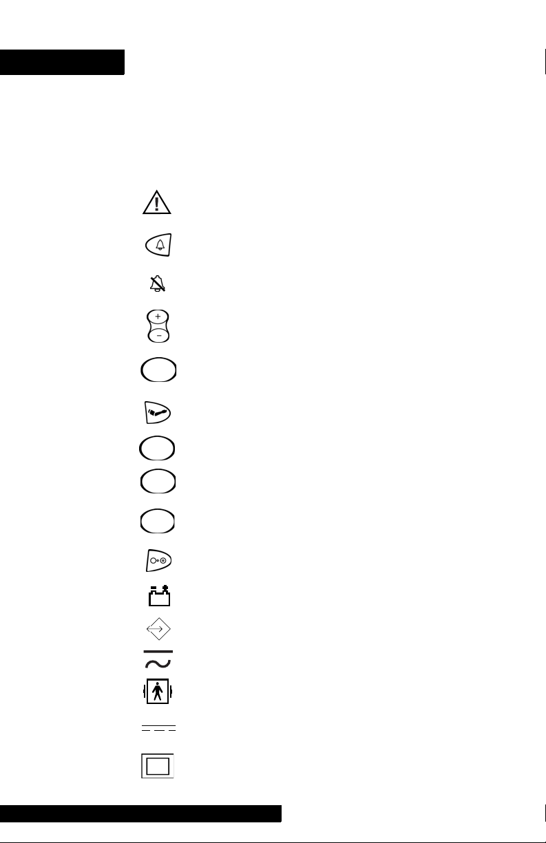
Symbols
The following symbols are associated with the ProCare
Monitor.
Note: The model of the Monitor determines which symbols
appear on it.
Attention, consult accompanying documents
Silence
Alarms
+ / - Increase / decrease adjustable settings
Menu
Inflate/Stop
Cycle
History
Print
On/Off
Battery Power
External communications port connector
Charging
Defibrillator-proof type BF equipment
External DC power input
Class II equipment according to IEC 60536
11
Page 22

Packaging label depicting the
transportation and storage
atmospheric pressure range
of 500 to 1060 hPa.
IPX1
The DINAMAP® ProCare Monitor is protected against
vertically falling drops of water and conforms with the IEC
529 standard at level of IPX1. Vertically falling drops shall
have no harmful effects to the Monitor.
12
Page 23

Getting Started
Page 24

14
Page 25
Getting Started
Unpacking the Monitor and Accessories
Before attempting to use the ProCare Monitor, take a few
minutes to become acquainted with the Monitor and its
accessories. Unpack the items carefully. This is also a good
time to check for any damage or accessory shortage. If there
is a problem or shortage, contact GE Medical Systems
Information Technologies.
It is recommended that all the packaging be retained, in case
the Monitor must be returned for service in the future.
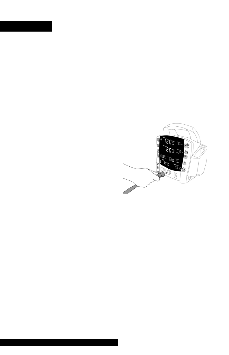
Setting up BP Connections
1. Connect the end of
the air hose that has
quick-release clips to
the BP connector on
the front of the
Monitor. Make sure
that the hose is not
kinked or
compressed.
Note: To disconnect
the hose from the
Monitor, squeeze the quick-release clips together and pull
the plug from the BP connector.
2. Select appropriate cuff size. Measure patient’s limb and
select appropriately sized cuff according to size marked
on cuff or cuff packaging. When cuff sizes overlap for a
specified circumference, choose the larger size cuff.
Precaution: Accuracy depends on use of proper size cuff.
3. Inspect cuff for damage. Replace cuff when aging, tearing,
or weak closure is apparent. Do not inflate cuff when
unwrapped.
Precaution: Do not use cuff if damaged.
4. Connect the cuff to the air hose. Refer to the BP section
for complete cuff connection instructions.
Warning: It is mandatory that the appropriate hose and
cuff combination be used. Any attempt to modify the
hose will inhibit the Monitor from switching between the
neonatal and adult measurement modes.
Note: Care should be taken in reconnecting the cuff to a
hose, ensuring that threads of the cuff and hose are in
alignment and no cross-threading occurs.
15
Page 26
5. Refer to the BP section of this manual for complete
instructions on taking an accurate BP determination.
Note: Use only CRITIKON
®
Blood Pressure Cuffs. The
size, shape, and bladder characteristics can affect the
performance of the instrument. Inaccurate readings may
occur unless CRITIKON
®
Blood Pressure Cuffs are used.
Refer to Appendix E for reorder codes.
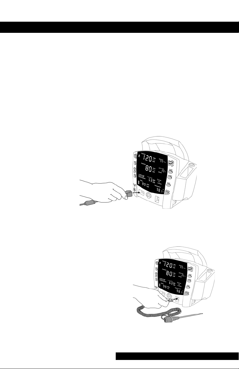
Setting up SpO2 Connections
1. Plug the appropriate SpO2 sensor into the SpO2 sensor
extension cable.
2. Then plug the SpO
sensor connector on the Monitor.
sensor extension cable into the SpO2
2
3. Refer to the applicable SpO
complete instructions on monitoring SpO
section of this manual for
2
.
2
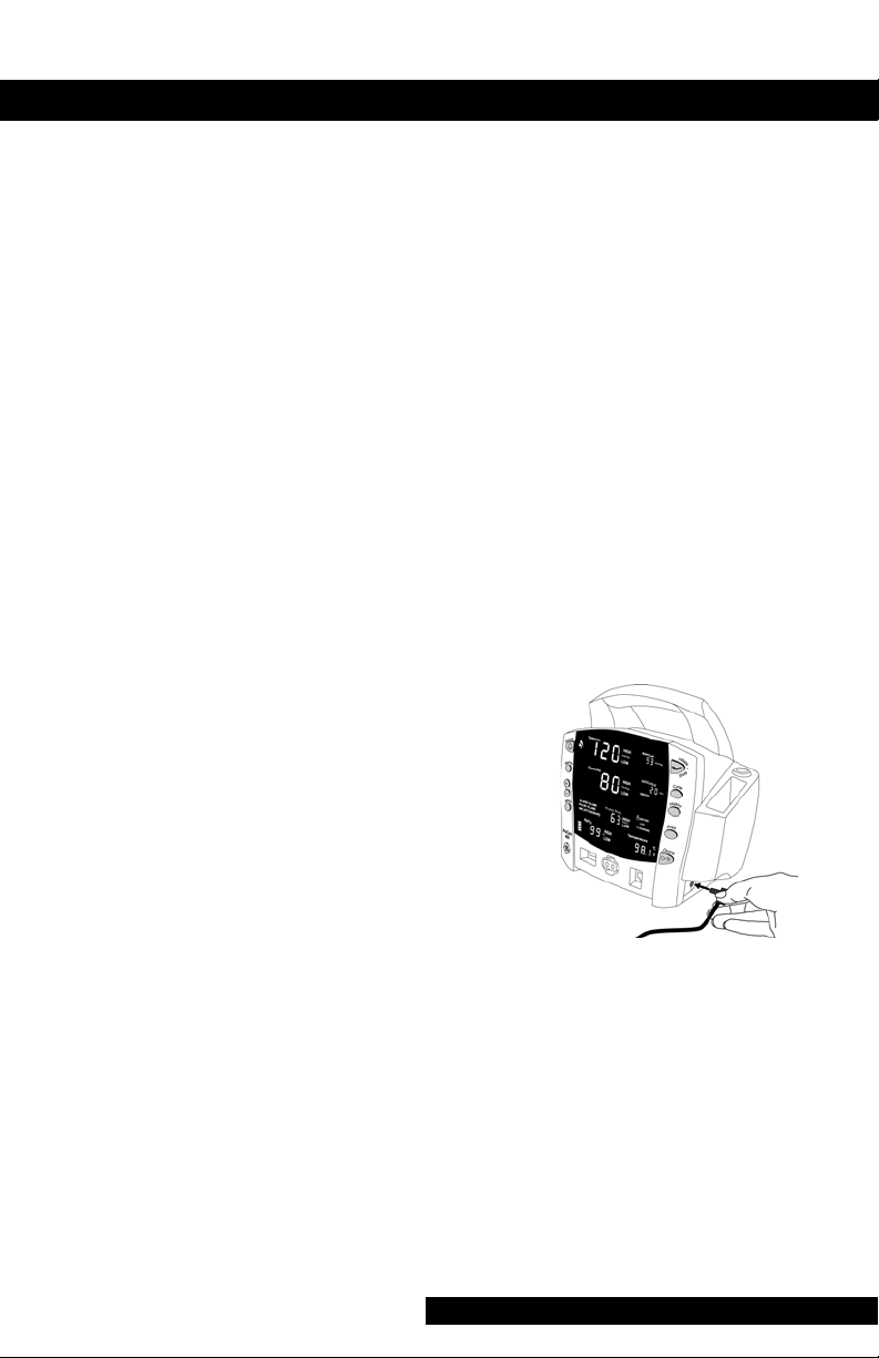
Setting up Temperature Connections
1. Connect the
temperature probe
cable to the
temperature probe
connector on the
Monitor.
2. Insert the temperature
probe into the probe
holster at the side of
the Monitor.
3. Refer to the
TURBO
section of this manual for complete instructions on taking
a temperature reading.
TEMP®
16
Page 27

Getting Started
Setting up the Printer (Installing the Paper)
1. With the Monitor
powered on, turn it so
that the side with the
printer is facing you.
2. While grasping the side
of the Monitor, lift the
printer door open by
placing your thumb in
the indented area and
pulling. The printer
door will pop open.
3.Place the roll of paper into the
compartment so that the end of
the paper comes off the right-side
of the roll (paper is wound
around the roll clockwise). Push
the roll all the way to the back of
the printer cavity, making sure the
paper extends out of the printer
cavity at least two inches.
4.Firmly press the door to close it.
5.Refer to the Printer section of
this manual for complete
instructions.
Power Sources
The ProCare Monitor is designed to operate from an internal leadacid battery (see “Specifications” in Product Overview section).
Notes
• The ProCare Monitor is not designed to operate without
an internal battery.
• Be sure to unplug the Monitor before transport.
Powering the Monitor: Battery and DC Supply
Prior to each use, inspect the power supply cord to ensure
proper connection and condition.
Before the ProCare Monitor is used for the first time, the
battery should be charged in the Monitor for at least 8 hours.
17
Page 28
With external DC power connected, the green CHARGING
indicator will light to indicate that the battery is charging.
When the Monitor is operating on battery power and the
BATTERY LOW alarm is not active, the BATTERY indicator is
backlit green. When the Monitor is operating on battery
power and the BATTERY LOW alarm is active, the BATTERY
indicator flashes green, the LOW indicator flashes amber,
and the medium priority alarm sounds until it is
acknowledged. Press the Silence button to acknowledge this
alarm. Once it is acknowledged, the indicators continue to
flash, but the audible alarm is silenced for 10 minutes. Once
the BATTERY LOW condition becomes active, the Monitor
should be connected to a DC power supply to recharge the
battery (refer to “Power Requirements” in Product Overview
section). If the Monitor continues to be used without
charging the battery, the Monitor eventually enters a fail-safe
mode (E13: BATTERY TOO LOW TO OPERATE). Refer to the
Alarms Section for information of an E13 error code.
Battery charging will take
place as long as the Monitor
remains connected to an
external DC power source.
Notes
• To prolong the life of the
battery, keep the
Monitor connected to a
DC power supply
whenever possible. NEVER allow the battery to become
completely discharged. A fully charged battery will
power the Monitor for approximately 5 hours. To ensure
full charge cycles, replace only with a recommended
battery. If the Monitor is to be stored for some time, first
charge the battery and then remove it and store it
separately from the Monitor.
18
Page 29

Getting Started
Turning the Monitor On and Off
To turn the ProCare Monitor on, push the power On/Off
button.
As the Monitor powers up, it will run a short self-test routine,
which will flash all the indicator lights and then beep the
warning speaker.
To turn the Monitor off, push the power On/Off button
again. This will terminate any measurements that may be in
progress and automatically deflate the cuff.
Note: Pressing and holding the On/Off button for 15
seconds will reset the CPU processor. After resetting the
CPU processor, check all the unit configuration settings.
Configuration Mode Settings
Monitor settings such as HIGH/LOW alarm settings changed
in the Clinical Mode will not be retained after the monitor is
powered off. To retain alarm and parameter settings, the
changes must be done in the configuration mode. Date/Time
settings are also entered in the configuration mode.
To enter the configuration mode: with the Monitor off, press
and hold the Menu button at the same time as pressing and
holding the On/Off button for 3 seconds. The Monitor
enters the configuration mode.
As the monitor turns on in the configuration mode, a brief
display appears showing the software revision and the BP
technology of the Monitor. These displays appear only
during the first part of the power up sequence and are not
selectable and cannot be changed.
Display
Major software revision Systolic
Minor software revision Diastolic
Type of BP technology min
19
Window
Page 30
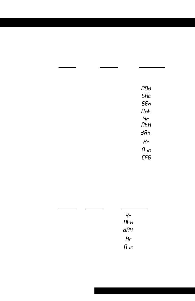
The Menu selections appear in the following order. Refer the
each manual section for settings options.
Note: Menu selections for a Masimo unit have three SpO
settings. Refer to the Masimo SpO
section for options.
2
2
Setting:
Window LED Display
• Inflate
Pressure: Diastolic XXX (numeric)
• SpO
• SpO2 Sat: SpO
• SpO2* Sensitivity: SpO
Mode: SpO
2
2
2
2
• Temp: °C or °F
• Year: Systolic
• Month: MAP/Cuff
• Day: Diastolic
• Hour: min
• Minute: min
• Mode: Systolic
*Masimo units only
Setting the Date and Time
To set the date and time on the ProCare Monitor, you must
access the configuration mode. Press MENU to skip the
default settings that do not require changes. The following list
shows the windows in which the date/time settings appear.
Setting:
• Year: Systolic
• Month: MAP/Cuff
• Day: Diastolic
• Hour: min
• Minute: min
Window LED Display
Procedures
1. Press the Menu button to move from one setting to
another. Use the +/- buttons to increment or decrement
the setting.
20
Page 31

Getting Started
Note: For the date and time to be saved, you must
advance the menu through the minute setting.
2. To exit the configuration mode, press the ON/OFF button.
3. To continue with other changes, press the Menu button.
CFG will appear in the Systolic window. To change
parameter settings, press the Menu button and select the
parameter function. To change alarm settings, press the
Alarms button.
Inflation Pressure Default Settings (Refer to the BP
Section for options)
Procedures
1. Enter the configuration mode: with the Monitor off, press
and hold the Menu button at the same time as pressing
and holding the On/Off button for 3 seconds, or press
Menu until the Inflate Pressure is lit on the display and the
pressure is displayed in the Diastolic window.
2. Use the +/- buttons to increment or decrement the inflate
pressure default setting. Increments are 5mmhg from
100mmhg to 250mmhg.
3. To exit the configuration mode, turn the unit off. To
continue with additional configuration settings, press
Menu.
Alarm Default Settings (Refer to Alarms Section for
options)
Procedures
1. Enter the configuration mode: with the Monitor off, press
and hold the Menu button at the same time as pressing
and holding the On/Off button for 3 seconds. After the
unit enters the configuration mode, press Alarms. At any
point in the configuration mode menu, Alarms default
may be selected.
2. To set or change the default setting, press the Alarms
button to select alarm setting. Use the +/- buttons to
increment or decrement the individual settings.
Note: For the Alarms default setting to be saved, you must
advance the menu through the SPO2 settings.
3. To exit the configuration mode, turn the unit off. To
continue with additional configuration settings, press
Menu.
21
Page 32

SPO2 Configuration Settings
Procedure for units with Nellcor® Technology
(Refer to the Nellcor® section for options)
1. Enter the configuration mode: with the Monitor off, press
and hold the Menu button at the same time as pressing
and holding the On/Off button for 3 seconds.
2. Press the menu button until
Rate window.
3. Use the +/- buttons to select the option.
4. Press the Menu button once. SAt appears in the Pulse
Rate window.
5. Use the +/- buttons to select the option.
6. To exit the configuration mode, turn the unit off. To
continue with additional configuration settings, press
Menu.
Procedure for units with Masimo® Technology
(Refer to the Masimo® section for options)
1. Enter the configuration mode: with the Monitor off, press
and hold the Menu button at the same time as pressing
and holding the On/Off button for 3 seconds.
2. Press the Menu button until
Rate window.
3. Use the +/- buttons to select the option.
4. Press the Menu button once. SAt appears in the Pulse
Rate window.
5. Use the +/- buttons to select the option.
6. Press the Menu button once. SEn appears in the Pulse
Rate window.
7. Use the +/- buttons to select the option.
8. To exit the configuration mode, turn the unit off. To
continue with additional configuration settings, press
Menu.
n0d appears in the Pulse
n0d appears in the Pulse
22
Page 33

Product Overview
Page 34

24
Page 35

Product Overview
Buttons
1 Silence button: Press to mute audible alarms. Any alarm
active that is acknowledgeable is also removed whenever
this key is pressed. When pressed after alarm sounds
(silence active), the silence icon (bell) lights to indicate
that audible alarms have been silenced for 2 minutes
2 Alarms button: Press to view or adjust parameter alarm
settings
3 +/- button (Plus/Minus): Press the + button to increase an
adjustable setting and the - button to decrease an
adjustable setting. This button is active only when a usersetting mode (limit or menu) is active
4 Menu button: Press to access menu settings that can be
adjusted while in clinical mode (i.e., ALARM VOLUME,
PULSE VOLUME, INFLATE PRESSURE; refer to Operating
Modes in this section for a description of clinical mode)
5 SpO
6 BP connector: BP cuff hose attaches here
7 Inflate/Stop button: Press to start a manual BP
8 Temperature probe holster: Temperature probe is stored
9 Cycle button: Press to start Auto Cycle or STAT mode
sensor connector: SpO2 sensor extension cable
2
attaches here
determination or stop any BP determination
here
25
Page 36

10 Temperature probe cover storage: Box of probe covers is
stored here
11 History button: Press to activate the history mode. When
activated, it displays the most recent entries stored. Press
and hold the button for 2 seconds to clear all entries
stored
12 Print button: Press to print currently displayed values or all
stored entries when in history mode
13 On/Off button: Controls on/off state of monitor; push for
power on and push again for power off
14 Temperature probe connector: Temperature probe cable
attaches here
26
Page 37

Product Overview
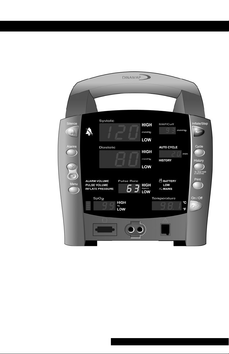
Front Panel
15 Silence icon: when Silence button is pressed after alarm
sounds (silence active), silence icon (bell) lights to indicate
that audible alarms have been silenced for 2 minutes
16 Systolic window: 3-digit red LED indicates measured
systolic BP in mmHg
17 Diastolic window: 3-digit red LED indicates measured
diastolic BP in mmHg
18 Alarm volume indicator: lights to indicate you are making
a change to the alarm volume
19 Pulse volume: lights to indicate you are making a change
to the pulse volume
20 Inflate pressure: lights to indicate you are making a
change to the inflation pressure
21 Pulse Rate window: 3-digit yellow LED shows pulse rate in
beats per minute
22 SpO
23 SpO
pulse indicator: Red LED bar flashes to indicate that
2
real-time pulse rate measurements are being derived from
SpO
signals
2
window: 3-digit red LED indicates oxygen saturation
2
in %
27
Page 38

24 MAP/Cuff window: 3-digit red LED indicates measured
MAP in mmHg and shows instantaneous cuff pressure
during BP determination
25 Min window: Displays the BP mode if manual or STAT is
the cycle time when in Auto Cycle mode
26 Battery power indicator: Green LED indicates the Monitor
is operating on battery power
27 Low battery power indicator: Yellow LED indicates LOW
charge status of internal battery
28 Charging indicator: Green LED indicates presence of
external power source and battery charging
29 Temperature window: 4-digit red LED indicates measured
temperature
28
Page 39

Product Overview
Rear Panel
30 Data interface connector: Host communications port
(15 pin D-type RS-232 serial port) for use only with
equipment conforming to IEC 601-1, configured to
comply with IEC 601-1-1
31 Printer compartment
29
Page 40

Left-Side Panel
32 Printer compartment
Right-Side Panel
33 External DC power socket: To be used with approved GE
Medical Systems Information Technologies AC-DC power
converter ONLY
30
Page 41

Product Overview
Windows
Each derived vital sign has an associated window for
displaying the value. For each window, the vital sign’s name
and unit of measure are labeled above and to the right of it,
respectively. An additional window--the min window--is
available for displaying the BP mode or chosen AUTO
CYCLE selection.
Indicators
Indicators are text messages and icons that are positioned on
the front of the Monitor and can be either backlit red or
green. For each vital sign that has user-adjustable limits, two
indicators (HIGH, LOW) appear to the right of its window.
Operating Modes
The ProCare Monitor can operate in one of four modes:
clinical, configuration, advanced configuration, and service.
Clinical mode is the Monitor’s normal operating mode.
While this mode is active, alarm limits and a few other
commonly used settings are adjustable. All parameters are
available for monitoring in this mode.
Configuration and advanced configuration modes display the
software revision and allows you to configure defaults for
some settings that are available in clinical mode, as well as
some less commonly used settings that are only adjustable in
these modes. No parameters are operable in these modes,
therefore, patient monitoring should be suspended.
Entering Configuration Mode
1. With the Monitor off, press and hold the Menu button at
the same time as pressing the On/Off button for 3
seconds.
2. The Monitor automatically switches on in configuration
mode.
Refer to the Service Manual for instructions for use
concerning advanced configuration and service mode.
31
Page 42

Parameter Modes
The ProCare Monitor has three parameter modes: offline,
ready, or operate.
A parameter is in offline mode when its vital sign(s) are not
checked against user-set limits, alarm conditions detected by
the parameter do not generate alarms, and no vital sign(s)
data is displayed.
A parameter is in ready mode when its vital signs are not
checked against user-set limits, alarm conditions detected by
the parameter do not generate alarms, and no vital sign(s)
data is displayed. However, information regarding the
connection of a sensor is communicated in this mode.
A parameter is in operate mode when the appropriate vital
signs are being checked against user-set limits and alarming
conditions detected by the parameter generate alarms. Vital
sign(s) data from the parameter is displayed.
When the Monitor is turned on and no sensor is connected,
the parameter remains in offline mode. Upon detection of a
sensor, the parameter auto-switches to ready mode. Upon
detection of valid patient data, the parameter auto-switches
to operate mode.
User Modes
The ProCare Monitor has four user modes that are available
during clinical operating mode: Menu, Cycle, Limit
Adjustment, and History.
The Menu mode allows you to access and change the three
settings associated with the following indicators: ALARM
VOLUME, PULSE VOLUME, AND INFLATE PRESSURE. To
activate this mode, press the Menu button. With each press
of the Menu button, the indicator appears in flashing green
with the associated value appearing in red in the Diastolic
window. As the Menu button is pressed, the indicators
appear in the following order: ALARM VOLUME, PULSE
VOLUME, AND INFLATE PRESSURE. To change the
associated value, simply use the +/- button to increment or
decrement, respectively. After 15 seconds of not pressing the
32
Page 43

Product Overview
Menu button, the Menu mode is automatically exited.
Otherwise, you can exit the Menu mode by pressing the
Menu button one more time after viewing the oldest entry.
Upon exiting Menu mode, the main monitoring screen is
displayed. Alarm and pulse volume settings are retained after
power-off. INFLATE PRESSURE is reset to its configured
default after power-off.
The Cycle mode allows you to access Auto Cycle and STAT
modes. Refer to the BP section for more information.
The History mode allows you to access the stored patient
data. Refer to the History section for more information.
The Limit Adjustment mode allows you to change alarm
limit settings that are used while monitoring a patient. All
limit alarm settings return to their default settings after
power-off. The range and increment/decrement steps for
each derived vital sign that has adjustable limits are
described in each parameter section. The step size specified
(which cannot be adjusted) tells how much the limit value
will change per increment/decrement key press and also
dictates how close together a pair of limits can be.
Limit-adjustable vital signs are displayed in the following
order: Systolic (HIGH, LOW), Diastolic (HIGH, LOW), Pulse
Rate (HIGH, LOW), and SpO
Note: The Temperature and MAP (mean arterial pressure)
vital signs are not checked against alarm limits.
(HIGH, LOW).
2
Sounds
The Monitor generates sounds based upon user interaction,
parameter events, parameter and system alarms, and low
battery alarms.
User interaction sounds include positive key tone and
negative key tone. The positive key tone sounds one highpitched tone when you press a button and the Monitor is
able to perform the intended function. The negative key tone
sounds three low-pitched tones when you press a button and
the Monitor is unable to perform the intended function.
33
Page 44

Parameter-specific sounds are related to the functioning of
each parameter: NIBP, Temperature, and SpO
. Refer to the
2
individual parameter sections for definitions and sounds.
Alarm-specific sounds include medium and high priority. The
medium-priority alarm sounds three high-pitched tones. The
high-priority alarm sounds three high-pitched tones followed
by two high-pitched tones. When alarms of both priorities
are active, only the high-priority alarm sound is audible.
A sound is generated when AC power is lost while patient
monitoring is active.
Power Sources
The ProCare Monitor is designed to operate from an internal
lead-acid battery. For replacement rechargeable batteries,
please refer to the Service section of this manual.
34
Page 45

Product Overview
Specifications
Mechanical
Dimensions Height: 9.7 in (24.7 cm)
Width: 8.6 in (21.9 cm)
without Temperature
10.0 in (25.4 cm) with Temp
Depth: 5.3 in (13.5 cm)
Weight, Including Battery 5.68 lb (2.58 kg)
Mountings Self-supporting on rubber feet
Portability Carried by handle
Classification Information Mode of operation:
continuous
Degree of protection against
harmful ingress of water: Dripproof IPX1
Power Requirements
Power Converter US: P/N: 2009460-001
Protection against electrical
shock: Class II
AC input: 120 VAC/60 Hz
24W
DC output voltage; 12VDC
at 1A
The AC mains power adapter
contains a nonresettable and
nonreplaceable fuse.
Power Converter UK & EUR: P/N UK: 2008538-001
P/N EUR: 2009539-001
Protection against electrical
shock: Class II
AC input: 230-240 VAC/50 Hz
92mA
DC output voltage; 12VDC
at 1A
35
Page 46

The AC mains power adapter
contains a nonresettable and
nonreplaceable fuse.
Monitor Protection against electrical
shock: Internally powered or
Class II when powered from
specified external power
supply.
DC input voltage: 12 VDC,
supplied from a source
conforming to IEC 601-1.
Fuses: The Monitor contains
four fuses. The fuses are auto-
resettable and mounted within
the Monitor. The fuses protect
the low voltage DC input, the
battery, the remote alarm
output, and the +5 V output
on the host port connector.
Battery: 6 volt, 3.3 amp-hours
protected by internal auto-
resetting fuse and thermal
protection.
Minimum operation time:
5 hrs (5 min cycle with adult
cuff at 25 °C, SpO
active at
2
60 bpm, Temp in monitor
mode) from full charge.
Time
for full recharge: Approx. 5 hrs
from full discharge when the
Monitor is switched off and
approx. 8 hrs when the Monitor
is switched on.
Environmental
Operating Temperature + 5 °C to + 40 °C
(+ 41 °F to + 104 °F)
Operating Atmospheric
Pressure 700 hPa to 1060 hPa
36
Page 47

Product Overview
Storage Temperature – 20 °C to + 50 °C
(– 4 °F to + 122 °F)
Storage/Transportation
Atmospheric Pressure 500 hPa to 1060 hPa
Humidity Range 5% to 95% noncondensing
Radio Frequency Complies with IEC
Publication 601-1-2 (April
1993) Medical Electrical
Equipment, Electromagnetic
Compatibility Requirements
and Tests and CISPR 11
(Group 1, Class B) for radiated
and conducted emissions.
The DINAMAP® ProCare Monitor is
protected against vertically falling drops of
IPX1
water and conforms with the IEC 529
standard at level of IPX1. No harmful
effects will come of vertically falling drops
of water making contact with the Monitor.
37
Page 48

38
Page 49

Printer
Page 50

40
Page 51

Printer
Description
The ProCare Monitor comes with an optional text-only
printer. Each time a printout is started, the following
information is printed: GE Medical Systems header, monitor
name; model number; current software revision; a place for
patient name and hand-written comments; a place for the
column labels, parameter labels, or unit of measure; date;
and vital signs data, if available. On some models, a pencil
icon
appears instead of the name and comments labels.
Installing the Paper
Refer to the Getting Started section for instructions.
Print Button
The Print button initiates two types of printouts: currently
displayed values and History.
By pressing the Print button while the main monitoring
screen is viewable, a printout of the currently displayed
values is generated. Since the currently displayed values may
have been derived at different times (e.g., the BP values are 5
minutes old, while Temp was just completed), the Monitor
prints the value along with a time stamp of when that value
was derived. Values are printed in order of the most recent
to the oldest.
By pressing the Print button when in History mode, all
entries currently stored in the history are printed in order of
the most recent to the oldest.
Note: If the Print button was pressed during the first 10
seconds of SpO
and pulse rate readings.
The availability of the printer is determined at the time the
printout is started. When the printer is unavailable, the Print
button makes a negative key sound when you press it. The
printer is unavailable if it is out of paper, too hot, or if the
battery is too low, or if the Monitor is in any of the following
modes: Cycle, Alarm limit adjustment, Menu, config, or service.
If no print is visible on the paper, check that the paper roll
has been installed in the correct position (refer to diagram).
monitoring, dashes will appear for SpO2
2
41
Page 52

To tear off the printout, use a slight sideways action to pull
the paper sharply up across the edge of the door.
Printer Alarms
When any of the alarm conditions occur, the alarm code
flashes in the min window and a high-priority alarm sounds.
When a printer alarm condition is active, you can
acknowledge the alarm by pressing the Silence button.
E10: PRINTER NO PAPER
This alarm is generated when the Print button is pressed and
the printer detects that there is no paper.
E11: PRINTER TOO HOT
This alarm is generated when a printout is in progress and the
printer becomes too hot to print.
E12: BATTERY TOO LOW TO PRINT
This alarm is generated when a printout is in progress and the
battery becomes too low to print.
Storage
Store thermal paper in a cool, dry place. The printed strip
(thermal paper recording) should not be
• exposed to direct sunlight,
• exposed to temperatures over 100 °F/38 °C or relative
humidity over 80%,
• placed in contact with adhesives, adhesive tapes, or
plasticizers such as those found in all PVC page
protectors.
Note: When in doubt about long-term storage conditions,
store a photocopy of the thermal paper recording.
Cautions
• The paper is thermally activated; therefore, do not store
it in a hot place as discoloration may result.
• Use only replacement paper rolls (P/N 770137 for
single rolls, 089100 for box of 10) from GE Medical
Systems - Accessories and Supplies.
42
Page 53

Alarms
Page 54

44
Page 55

Alarms
The ProCare Monitor provides visible and audible indications
of patient-, and system-related alarm conditions. An alarm
can generate an audible indication, visual indication, alarm
message code, and electronic record in the history.
Alarm Codes
All alarm indications are accompanied by an audible signal
unless the Silence button is selected. A microprocessor
system failure will generate a high-pitched audible alarm
regardless of the setting of the Silence button.
There are three categories of alarms: patient-related (limit
and parameter status alarms), system-related (printer, battery,
and memory alarms), and system failures.
Adjusting Alarm Limits
Alarms Button
Pressing the Alarms button activates the limit adjustment
user mode. When the limit adjustment mode is initially
activated, it first displays the systolic high limit value with the
HIGH indicator flashing in red. With each subsequent press
of the Alarms button, the next limit in the sequence is
displayed for adjustment. Press the + button to increase the
displayed limit value and the - button to decrease the
displayed limit value.
To exit limit adjustment mode after setting alarms, you must
progress through all limits until you reach the last one. Then,
after reaching the last limit, immediately press the Alarms
button. The main monitoring screen appears indicating that
you have exited Alarms mode. If monitoring is active, the
current vital signs appear after you have completed your
alarm setting changes. Or, you can let the mode time-out by
not touching the Alarms button until the main monitoring
screen appears indicating that you have exited Alarms mode.
The Monitor returns to all default limit settings after poweroff; these defaults are adjustable via configuration mode.
Adjustable vital signs limits are displayed in the following
order: Systolic (HIGH, LOW), Diastolic (HIGH, LOW), Pulse
Rate (HIGH, LOW), and SpO
parameter section for ranges.
(HIGH, LOW). Refer to each
2
45
Page 56

Note: The Temperature and MAP vital signs are not checked
against alarm limits.
Adjusting the Alarm Volume
You can adjust the alarm volume by pressing the Menu
button. ALARM VOLUME will flash in green with the value in
the Diastolic window. You can set the ALARM VOLUME
range from 1 to 10 (10 being the loudest). Changing the
volume applies to all alarms.
The positive key tone that sounds when you press the +/buttons relates directly to the user-set alarm volume. Refer to
User Modes.
Silencing and Acknowledging an Alarm
Silence Button
To silence a patient-related alarm (limit and parameter status
alarms) at anytime, press the Silence button. The silence icon
(a bell) lights to indicate that audible alarms have been
silenced for 2 minutes.
Some patient- and system-related alarms are
acknowledgeable. (Refer to the Alarm Message Codes table
at the back of this section.) For acknowledgeable alarms that
are active when the Silence button is pressed, any associated
audible or visual indication is removed and any associated
alarm message code is no longer displayed.
The silence icon has three states:
• Solid red: silence icon is active.
• Blinking red: alarm silence is not active and at least one
alarm condition is active.
• Off: alarm silence is not active and no alarm condition is
active.
Alarm Sounds
The Monitor produces two different alarm sounds based
upon the priority of the alarm: medium and high priority. The
medium-priority alarm sounds three high-pitched tones. The
high-priority alarm sounds three high-pitched tones followed
46
Page 57

Alarms
by two high-pitched tones. When alarms of both priorities
are active, only the high-priority alarm sound is audible.
Alarm Detection and Priorities
Limit Alarms
The Monitor checks each derived vital sign (except MAP and
Temperature) against user-set limits. A high-limit alarm is
generated when that value is greater than its high limit. A
low-limit alarm is generated when that value is less than its
low limit. All limit alarms are considered high priority.
Parameter Range
Systolic High 35 - 290 200
Systolic Low 30 - 285 80
Diastolic High 15 - 220 120
Diastolic Low 10 - 215 30
Pulse Rate High: NELLCOR 35 - 250 150
Pulse Rate Low: NELLCOR 30 - 245 50
Pulse Rate High: MASIMO 35 - 235 150
Pulse Rate Low: MASIMO 30 - 230 50
High 21 - 100 100
SpO
2
SpO
Low 20 - 99 90
2
*To change Alarm Default settings, refer to Config Mode in
Getting Started section.
Factory
Default*
When a limit violation occurs, the following happens:
• The derived vital sign that is out of limits and the
associated HIGH or LOW indicator flash.
• The high priority alarm sound becomes audible unless
silence is active.
47
Page 58

Parameter Status Alarms
The Monitor generates parameter status alarms when
unusual patient or sensor conditions are detected. All
parameter status alarms are considered high priority alarms.
Refer to the Alarm Message Codes table in this section.
When a parameter status alarm occurs, the following
happens:
• Its code flashes in the associated window.
• The high priority alarm sound becomes audible unless
alarm silence is active.
Printer Alarms
Refer to Printer section.
Memory Alarms
Memory alarms occur when battery-backed RAM is
corrupted. When it occurs, all settings are reset to their
factory defaults. When detected, the alarm message code
appears in the Systolic window and the medium-priority
alarm sounds.
Battery Alarms
Two types of battery alarms exist: a BATTERY LOW alarm
indicating the battery needs recharging and an E13 BATTERY
TOO LOW TO OPERATE indicating that the battery is so low
monitoring has stopped. For information on the BATTERY
LOW alarm, refer to “Powering the Monitor” in the Getting
Started section.
When the E13 BATTERY TOO LOW TO OPERATE is
detected, the Monitor ceases all monitoring, blanks the
display except for the Low Battery indicators, and displays
E13 in the Systolic window. A medium priority alarm sounds
and continues to sound for 10 minutes, unless the unit is
powered off.
After the first 10 minutes, if the Monitor was idle (not
monitoring) when the condition was detected, then it
automatically powers off.
48
Page 59

Alarms
Otherwise, if the unit had been monitoring when the
condition was detected, the alarm changes to the critical
priority alarm level. The Monitor continues to display the
Low Battery indicators and error code E13 as before. This
continues for 10 minutes, unless the unit is powered off. At
the end of this period, if the Monitor has not be shut off, it
then automatically powers off.
System Failure Alarms
System failures are caused by a system software or hardware
failure. When a system failure occurs, the error code is
displayed in the Systolic window, and the Monitor enters a
fail-safe mode in which a constant alarm tone sounds for up
to 10 minutes before the tone is automatically switched off.
Refer to the Alarm Message Codes table in this section.
49
Page 60

Specifications
Default Settings
Alarm Volume 5
50
Page 61

Alarms
Alarm
Message
Code
E89 BP NO DETERMINATION Yes
E85 BP LEVEL TIMEOUT Yes
E84 BP TOTAL TIMEOUT Yes
E83 BP INFLATION TIMEOUT Yes
E82 EXCESS AIR IN CUFF Yes
E80 BP OVERPRESSURE Yes
E21 SPO2 REPLACE SENSOR Yes
E22
E23 SPO2 SENSOR OFF FINGER Yes
E25 SPO2 NO SIGNAL Yes
Alarm Detected
SPO2 REPOSITION SENSOR
(Masimo ONLY)
Acknowledgeable by
pressing Silence?*
Yes
E61 TEMP PROBE BROKEN No
E63
E66 TEMP PROBE TOO HOT No
E10 PRINTER NO PAPER Yes
E11 PRINTER TOO HOT Yes
E12 BATTERY TOO LOW TO PRINT Yes
E13 BATTERY TOO LOW TO OPERATE No
TEMP DISCONNECTED OR
WRONG TYPE PROBE
51
Yes
Page 62

E00 MEMORY LOST Yes
Alarm
Message
Code
930
940
950
951
952
970
971
Alarm Detected
SYSTEM FAILURE**
SpO2 no status from module for 30 ±10s,
fatal error reported by module
SYSTEM FAILURE**
TEMP data samples less than 45 in 5s interval
SYSTEM FAILURE**
NIBP pump on during idle or overcurrent
detected
SYSTEM FAILURE**
NIBP valve stuck closed during cuff typing
SYSTEM FAILURE**
NIBP PT2 higher than 150 for greater than
15s while idle
SYSTEM FAILURE**
Time base failure
SYSTEM FAILURE**
RAM test failure
Acknowledgeable by
pressing Silence?*
No
No
No
No
No
No
No
972
SYSTEM FAILURE**
ROM checksum failure
No
SYSTEM FAILURE**
973
Secondary SPI communication error during
initialization
No
SYSTEM FAILURE**
974
Calibration data invalid on initialization or
unit never calibrated
No
SYSTEM FAILURE**
975
*Acknowledging an alarm by pressing the Silence button, cancels the alarm.
** Refer to the ProCare Service Manual or call Technical Support for definitions and
instructions.
Calibration data storage exhausted while
saving data in cal mode
No
52
Page 63

History
Page 64

54
Page 65

History
Description
The History mode allows you to access the stored patient
data. The ProCare Monitor can hold up to 40 stored entries
in history. When full, the oldest entry is removed so the most
recent entry can be stored. Additionally, entries are
automatically removed when they become older than 24 hours.
The age of each entry is maintained and displayed in the min
window with a minus sign (-) in front of it when other data
stored for that entry is displayed. For entries that are greater
than 59 minutes old, the age is displayed as HH:MM
(hour:min). For entries that are less than or equal to 59
minutes old, the age is displayed in total minutes.
When viewing entries in History that are out of limits, the
corresponding HIGH or LOW indicator appears in red.
An entry is stored in history at the completion of a BP
determination and at the completion of a successful
predictive temperature measurement. At the end of a BP
determination, systolic, diastolic, MAP, pulse rate, and SpO
values are stored. At the end of a temperature determination,
only the temperature value is stored.
2
Buttons Associated with History
To activate the History mode, press the History button. The
HISTORY indicator flashes green while this mode is active.
With each press of the History button, the patient data
stored with the next oldest entry is displayed. Entries are
displayed from the most recent to the oldest. For example,
the most recent entry could have an age of -0 minutes and
the oldest entry could have an age of -23:59.
After 15 seconds of not pressing the History button, the
History mode is automatically exited. Otherwise, you can
exit the History mode by pressing the History button one
more time after viewing the oldest entry. Upon exiting
History mode, the main monitoring screen is displayed.
Erasing Stored History
To erase stored patient data, press and hold the History
button for a minimum of 2 seconds. All entries that were
55
Page 66

stored in history, as well as any patient data displayed on the
Monitor that relates to the previous determination or the
previous temperature measurement is erased.
Windows Associated with History
Each window on the Monitor can be active during History
mode. When the History button is pressed the patient data
stored for each entry is displayed in the applicable windows.
Patient data is displayed from most recent to oldest,
indicated by the age in the min window.
Indicators Associated with History
The History indicator is used to show the state of the history
mode. When History mode is active, the History indicator
flashes green.
56
Page 67

BP
Page 68

58
Page 69

BP
Description
The BP parameter in the ProCare Monitor is available with
two types of BP technologies: one calibrated to intra-arterial
pressure and one calibrated to the auscultatory method
(specific technologies are available in select markets). Please
refer to the front of your ProCare Monitor to see which BP
technology your monitor contains. The monitors containing
auscultatory technology will have an auscultatory label
above the model number on the front of the Monitor. Then,
refer to the Appendix A: Principles of Noninvasive Blood
Pressure Determination for specific information regarding
both technologies. All user interface options, instructions for
use, and alarms will be the same for both technologies. The
BP parameter is included in all models. Blood pressure is
monitored noninvasively in the ProCare Monitor by
oscillometric method.
Note: For neonatal populations, the reference is always the
intra-arterial pressure monitoring method.
The ProCare Monitor has three BP modes: 1. Manual, 2. Auto
Cycle, and 3. STAT. The mode is selected by the user. The
actual BP determination is automated and, once it is
complete, the values for systolic pressure, diastolic pressure,
mean arterial pressure, and pulse rate are shown in their
respective windows.
Before each BP determination, the Monitor performs a test
to ensure that the cuff pressure is below a specified level.
The determination is delayed until this condition is met. The
Monitor senses the type of hose being used and
automatically uses adult/pediatric monitoring parameters or
neonatal monitoring parameters, as appropriate.
Audible and visible alarms occur when any of the values for
systolic pressure, diastolic pressure, or pulse rate are outside
their selected high or low limits.
Note: The Monitor will continue to operate until the battery
is completely depleted in order to obtain the full use of the
battery. However, if the battery reaches its “empty” point
during a BP determination, it will simply stop in the middle of
the determination.
59
Page 70

Instructions for cleaning and disinfecting BP cuffs are in
Appendix B.
General Warnings
• Connect cuffs and inflation systems only to systems
designed for non-invasive blood pressure monitoring.
Devices with luers and locking luer connectors may be
inadvertently connected to intravascular fluid systems
that may allow air to be pumped into a blood vessel.
•The ProCare Monitor will not measure blood pressure
effectively on patients who are experiencing seizures or
tremors.
• Arrhythmias will increase the time required by the
ProCare Monitor to determine a blood pressure and
may extend the time beyond the capabilities of the
Monitor.
• In Manual mode, the ProCare Monitor displays the
results of the last blood pressure determination for 30
minutes or until another determination is completed. If
a patient’s condition changes between one
determination and the next, the Monitor will not detect
the change or indicate an alarm condition.
• Devices that exert pressure on tissue have been
associated with purpura, skin avulsion, compartmental
syndrome, ischemia and/or neuropathy. To minimize
these potential problems, especially when monitoring
at frequent intervals or over extended periods of time,
make sure the cuff is applied appropriately and
examine the cuff site and the limb distal to the cuff
regularly for signs of impeded blood flow.
• Do not apply external pressure against cuff while
monitoring. Doing so may cause inaccurate blood
pressure values.
• Use care when placing cuff on extremity used to
monitor other patient parameters.
•The ProCare Monitor is designed for use only with
CRITIKON
®
dual-tube cuffs.
60
Page 71

BP
• Use only accessories approved for use with DINAMAP®
Monitors. Failure to use recommended accessories may
result in inaccurate readings.
• Blood pressure cuffs should be removed from the
patient when the Monitor is powered off. If the
extremity remains cuffed under these conditions or if
the interval between blood pressure determinations is
prolonged, the patient’s limb should be observed
frequently and the cuff placement site should be
rotated as needed.
General Cautions
• Accuracy of BP measurement depends on using a cuff
of the proper size. It is essential to measure the
circumference of the limb and to select the proper size
cuff. In addition, the air hoses are color-coded
according to patient population. The gray 12- or 24-foot
hose (3.66 m or 7.3 m) is required on patients who
require cuff sizes from infant through thigh cuffs. The
light blue 12-foot hose (3.66 m) is required for the
neonatal cuff sizes #1 through #5.
• If it becomes necessary to move the cuff to another
limb, make sure the appropriate size cuff is used.
• The pulse rate derived from a BP determination may
differ from the heart rate derived from an EKG
waveform because the ProCare Monitor measures
actual peripheral pulses, not electrical signals or
contractions from the heart. Differences may occur
because electrical signals at the heart occasionally fail
to produce a peripheral pulse or the patient may have
poor peripheral perfusion. Also, if a patient’s beat-tobeat pulse amplitude varies significantly (e.g., because
of pulsus alternans, atrial fibrillation, or the use of a
rapid-cycling artificial ventilator), blood pressure and
pulse rate readings can be erratic, and an alternate
measuring method should be used for confirmation.
General Notes
• A patient’s vital signs may vary dramatically during the
use of cardiovascular agents such as those that raise or
61
Page 72

lower blood pressure or those that increase or decrease
heart rate.
• Several conditions may cause the BP parameter to
calculate and display only the mean arterial pressure
(MAP) without systolic and diastolic readings. These
conditions include very low systolic and amplitude
fluctuations, so an accurate calculation for these values
can’t be made (e.g., patient in shock); too small of a
difference between systolic and MAP calculations in
relationship to the difference between diastolic and
MAP; or a leak has occurred in the ProCare Monitor. If
only the MAP value is displayed, an alarm message
code is displayed in the systolic window, while the
diastolic window remains blank.
• This equipment is suitable for use in the presence of
electrosurgery.
Buttons Associated with BP
The buttons associated with BP are Inflate/Stop and Cycle.
The Inflate/Stop button starts and stops BP determinations.
When a determination is in progress, pressing this button
stops the determination. While in STAT mode, pressing this
button cancels STAT mode, as well a determination if in
progress. When in Auto Cycle mode, pressing this button
starts a determination or cancels a determination if in
progress; it does not change the mode.
Note: While an E80: BP OVERPRESSURE alarm is active, all
presses of this button are ignored.
The Cycle button initiates the Cycle mode, which is where
you can choose STAT or an auto cycle time. Cycle mode
selections appear in the following order: Stat, 1, 2, 3, 4, 5,
10, 15, 20, 30, 60, 90, 120 (minutes), and - - (two dashes).
Choose Stat to start STAT mode. Choose 1-120 to select the
desired cycle time and start Auto Cycle mode. When you
reach the desired setting, do not press the Cycle button
again. After 2 seconds the cycle mode is deactivated.
Choose the two dashes to cancel Auto Cycle mode.
Note: While an E80: BP OVERPRESSURE alarm is active, all
presses of this button are ignored.
62
Page 73

BP
Windows Associated with BP
The windows associated with BP are Systolic, Diastolic,
MAP/Cuff, Pulse Rate, and min. The Systolic, Diastolic,
MAP/Cuff, and Pulse Rate (if SpO
are automatically cleared when a new BP determination is
started. In manual mode, the displayed information is also
cleared when it becomes older than 30 minutes.
The Systolic and Diastolic windows display values after a
determination has completed successfully. While in STAT
mode, the Systolic window flashes the early systolic value if it
is available.
The MAP/Cuff window displays the derived mean arterial
pressure (MAP) following the completion of a successful
determination. During any type of BP determination, the
pressure inside the cuff appears in this window.
The min window displays the BP mode of operation and the
age of the previous BP determination. When both types of
information are present, they flash alternately in this window.
When in Manual mode, two dashes (- -) are displayed. When
in Auto Cycle mode, the chosen Cycle time is displayed (e.g.,
15) When in STAT mode, Stat is displayed. When displayed,
the age of the previous BP determination is preceded by a
minus sign (e.g., - 5).
is not active) windows
2
Indicators Associated with BP
The indicators associated with BP are Systolic HIGH and
LOW, Diastolic HIGH and LOW, AUTO CYCLE and
HISTORY.
The AUTO CYCLE indicator appears solid green when Auto
mode is on. It flashes green when changes are being made to
the current BP mode (e.g., Cycle mode is active). The
HISTORY indicator appears solid green when the age of the
previous BP determination is displayed in the min window.
Parameter Modes
The BP parameter is in operate mode upon power-up. It does
not have a ready mode.
63
Page 74

BP Modes of Operation
The ProCare Monitor has three BP modes: 1. Manual, 2. Auto
Cycle, and 3. STAT. The mode is selected by the user. BP
determinations are automated and, upon completion, the
values for systolic pressure, diastolic pressure, mean arterial
pressure, and pulse rate are shown in their respective
windows.
Manual BP Determinations
Manual mode allows you to take one blood pressure
determination. Manual mode is always the BP mode of
operation upon power-up. A normal, uninterrupted Manual
determination takes about 40 seconds. Following a
determination, the cuff pressure must drop below 5 mmHg
(neonate) or 15 mmHg (adult) before another determination
can be started.
Manual BP determinations are started by pressing the
Inflate/Stop button. To stop a Manual BP determination
press the Inflate/Stop button. The values displayed in the
Systolic, Diastolic, MAP, and Pulse Rate (if SpO
active) windows are cleared after 30 minutes have lapsed.
Auto Cycle Determinations
Auto Cycle mode allows you to take multiple determinations
at user-defined intervals. In the Auto Cycle mode, the
pressure must be below 5 mmHg (neonate) or 15 mmHg
(adult) for at least 30 seconds before the next auto
determination can be started.
is not
2
Auto Cycle mode is started by selecting the Cycle button.
When in Auto Cycle mode, the AUTO CYCLE indicator
appears solid green. Manual determinations can be taken
while in Auto Cycle mode without affecting when the next
auto determination is to start. You can also change the time
interval while in Auto Cycle mode.
Once the Cycle button is pressed, the first Auto Cycle
determination is started, and the time between
determinations appears in the min window. You can change
the time interval between Auto Cycle determinations by
continuing to press the Cycle button until you reach the
64
Page 75

BP
desired time interval. Time interval selections appear in the
following order: Stat, 1, 2, 3, 4, 5, 10, 15, 20, 30, 60, 90, 120
(minutes), and - - (two dashes). When you reach the desired
time interval, do not press the Cycle button again; after 2
seconds, the chosen time interval is retained and remains in
the min window.
Pressing the Cycle button when in Auto Cycle mode
activates Cycle mode again with two dashes (- -) appearing in
the min window. If you press the Cycle button immediately
after the first press, the next time interval appears in the min
window. If you do not press the Cycle button immediately
after the first press, Cycle mode is deactivated. Press the
Inflate/Stop button to stop the determination in progress
without canceling the Auto Cycle mode. Choose the two
dashes (- -) to cancel Auto Cycle mode.
If the first Auto Cycle determination results in a limit alarm,
another repeat determination is taken to verify the alarm.
This occurs only once.
Whenever an Auto Cycle determination results in a E89: BP
NO DETERMINATION alarm, up to nine more repeat
determinations are attempted in order to achieve valid
values. If at any time during this repeat cycle, the BP NO
DETERMINATION alarm is acknowledged by pressing the
Silence button or the Inflate/Stop button, additional
determinations are not attempted. If the repeat cycle
completes all nine repeat determinations without reaching a
valid value, the Monitor returns to normal Auto Cycle mode.
However, an Auto Cycle mode determination must
complete successfully before a repeat cycle will follow a
future Auto Cycle mode determination that results in an E89:
BP NO DETERMINATION alarm.
STAT BP Determinations
STAT mode allows you to take as many determinations as
possible within a 5-minute time period. The Monitor will
begin another determination once the pressure is below 5
mmHg for 8 seconds (neonates) or 15 mmHg for 4 seconds
(adults), unless the 5-minute period has ended or STAT mode
has been canceled.
65
Page 76

Note: BP and BP-derived pulse rate alarm limits are disabled
while in Stat mode.
STAT BP determinations are started by selecting the Cycle
button. Once the Cycle button is pressed, choose Stat. The
Monitor automatically begins a 5-minute period of STAT
determinations.
Note: If the Monitor was previously in Auto mode, the first
STAT BP determination begins after 2 seconds.
After the first STAT determination, an early systolic value
flashes in the associated window. If STAT mode is started
when a determination is already in progress, that
determination becomes the first in the series of STAT
determinations. At the end of STAT mode, the BP mode prior
to entering STAT mode is resumed. To cancel STAT mode,
press the Inflate/Stop button.
User Settings
Mode Settings
There is one mode setting associated with this parameter:
Cycle. The Cycle mode is started by pressing the Cycle
button. While the Cycle mode is active, Cycle selections are
displayed in the min window. Cycle selections appear in the
following order: Stat, 1, 2, 3, 4, 5, 10, 15, 20, 30, 60, 90,
120, - - .
Limit Settings
There are two limit settings associated with this parameter:
HIGH and LOW. Both limit settings are available for Systolic
and Diastolic windows. The range for Systolic HIGH is 35 to
290 mmHg; the range for Systolic LOW is 30 to 285 mmHg.
The range for Diastolic HIGH is 15 to 220 mmHg; the range
for Diastolic LOW is 10 to 215 mmHg. The settings appear in
increments of 5 mmHg.
Neonate Settings
The Monitor determines if a neonate BP cuff is being used
and then checks the systolic limit and adjusts it to an
appropriate limit for neonates.
66
Page 77

BP
Menu Settings
The INFLATE PRESSURE menu setting is associated with the
BP parameter. This option lets you adjust the target pressure
that the Monitor initially pumps to for the next
determination. The settings appear in increments of 5
mmHg. The range available is 100 mmHg to 250 mmHg. If
the Monitor senses a neonate BP cuff in use, it checks the
systolic limit and adjusts it to an appropriate limit for
neonates.
When you change the target pressure, any values from the
previous determinations are cleared from their associated
windows.
Note: Default inflation pressure can be changed in Config
Mode. Refer to the Getting Started section.
Manual determinations use the value chosen for INFLATE
PRESSURE as their target inflation pressure unless a
determination is started within 2 minutes of the completion
of a previous determination. For a determination that is
started within 2 minutes of the previous determination, the
target inflation pressure is adaptive (calculates the target
inflation pressure based on the previous determination). For
all Auto Cycle and STAT determinations (with the exception
of the first determination of the series), the target inflation
pressure is always adaptive. If recent determination results
are available, the target pressure is derived from the last
systolic value.
Sounds Associated with BP
There is one tone associated with this parameter: a single
tone. The tone sounds at the completion of any BP
determination.
Procedures
1. Connect the end of the air hose which has quick-release
clips to the BP connector on the front of the Monitor.
Make sure that the hose is not kinked or compressed.
Note: To disconnect the hose from the Monitor, squeeze
the quick-release clips together and pull the plug from the
BP connector.
67
Page 78

2. Select the appropriate blood pressure measurement site.
Because normative values are generally based on this site
and as a matter of convenience, the upper arm is
preferred. When upper arm size or shape, the patient’s
clinical condition, or other factors prohibit use of the
upper arm, the clinician must plan patient care
accordingly, taking into account the patient’s
cardiovascular status and the effect of an alternative site
on blood pressure values, proper cuff size, and comfort.
The figure shows the recommended sites for placing cuffs.
Warning: Do not place the cuff on a limb being used for
intravenous infusion or any area where circulation is
compromised or has the potential to be compromised.
3. If patient is standing, sitting, or inclined, ensure that cuffed
limb is supported to maintain cuff at level of patient’s
heart. If cuff is not at heart level, the difference in systolic
and diastolic values due to hydrostatic effect must be
considered. Add 1.80 mmHg to values for every inch
(2.54 cm) above heart level. Subtract 1.80 mmHg from
values for every inch (2.54 cm) below heart level.
4. Select appropriate cuff size. Measure patient’s limb and
select appropriately sized cuff according to size marked
on cuff or cuff packaging. When cuff sizes overlap for a
specified circumference, choose the larger size cuff.
Precaution: Accuracy depends on use of proper size cuff.
Caution: Do not use an infant cuff with an auscultatory
reference DINAMAP
®
ProCare Monitor. The neonatal
#5 cuff and neonatal hose may be used on patients with
an arm circumference of 8 - 15 cm.
Note: Use only CRITIKON
®
Blood Pressure Cuffs. The
size, shape, and bladder characteristics can affect the
performance of the instrument. Inaccurate readings may
occur unless CRITIKON
®
Blood Pressure Cuffs are used.
68
Page 79

BP
5. Inspect cuff for damage. Replace cuff when aging, tearing,
or weak closure is apparent. Do not inflate cuff when
unwrapped.
Precaution: Do not use cuff if structural integrity is suspect.
6. Connect the cuff to the air hose.
7. Inspect patient’s limb prior to application.
Precaution: Do not apply cuff to areas where skin is not
intact or tissue is injured.
8. Palpate artery and place cuff so that patient’s artery is
aligned with cuff arrow marked “artery.”
9. Squeeze all air from cuff and confirm that the connection
is secure and unoccluded and that tubing is not kinked.
10.Wrap cuff snugly around the patient’s limb. Cuff index
line must fall within the range markings. Ensure that hook
and loop closures are properly engaged so that pressure
is evenly distributed throughout cuff. If upper arm is used,
place cuff as far proximally as possible.
11.Proper cuff wrapping should be snug, but should still
allow space for a finger between patient and cuff. Cuff
should not be so tight as to prevent venous return
between determinations.
Warning: Using a cuff that is too tight will cause venous
congestion and discoloration of the limb, but using a
cuff that is too loose may result in no readings and/or
inaccurate readings.
12.Proceed with monitoring in the Manual, Auto Cycle, or
STAT mode.
What to do When Taking BPs on Different Patients
To ensure the previous patient’s BP will not be used for
adaptive target inflation pressure when taking a BP on a new
patient, you can 1.) clear the history by holding the history
key for more than 2 seconds, or 2.) if in manual mode, wait
for more than 2 minutes since the last determination was
taken on the previous patient.
In manual mode, the Monitor will not use the displayed BP
values for adaptive target inflation pressure if it has been
more than 2 minutes since the end of the previous
determination. In manual mode, the BP values are displayed
for a maximum of 30 minutes. In auto mode, the displayed
BP values are used for adaptive target inflation pressure
independant of the age of the displayed values.
69
Page 80

Cuff Connections
Quick-Disconnect
Air Hose
Push and twist the male
slip hose connector into
the cuff connector to
ensure a tight fit.
Neonate Air Hose
Push and twist the male
slip hose connector into
the cuff connector to
ensure a tight fit.
Alarms
Alarm Acknowledgeable
by pressing Silence?
BP SYSTOLIC HIGH yes
BP SYSTOLIC LOW yes
BP DIASTOLIC HIGH yes
BP DIASTOLIC LOW yes
E89: BP NO DETERMINATION yes
E85: BP LEVEL TIMEOUT yes
E84: BP TOTAL TIMEOUT yes
E83: BP PUMP TIMEOUT yes
E80: BP OVERPRESSURE yes
E82: EXCESS AIR IN CUFF yes
The alarm codes appear in the Systolic window. When an
alarm is active, it can be acknowledged by starting a new
determination, with the exception of the E80: BP
OVERPRESSURE alarm. BP OVERPRESSURE can only be
acknowledged by pressing the Silence button. During STAT
mode determinations, systolic, diastolic and BP-derived pulse
rate values are not checked against their limits.
Critikon US Patents
4,360,029; 4,501,280; 4,546,775; 4,638,810; 5,052,397;
4,349,034; 4,543,962; 4,627,440; 4,754,761; 5,170,795
European Patents
EP122123, EP205805, EP207807
70
Page 81

BP
Specifications
Cuff Pressure Range 0 to 290 mmHg (adult/ped)
(Normal operating range) 0 to 140 mmHg (neonate)
Blood Pressure Accuracy Meets or exceeds ANSI/AAMI
standard SP-10 (mean error ≤5
mmHg, standard deviation ≤8
mmHg)
Maximum Determination 120 s (adult/ped)
Time 85 s (neonate)
Overpressure Cutoff 300 to 330 mmHg (adult/ped)
150 to 165 mmHg (neonate)
Pulse Rate Range
Pulse Rate Accuracy ± 3.5%
Factory Default Settings
Systolic Limits (mmHg) HIGH: 200
LOW: 80
Diastolic Limits (mmHg) HIGH: 120
LOW: 30
Inflation Pressure* 160 mmHg (adult/ped)
Cycle button 15
*Default inflation pressure can be changed in Config Mode. Refer to the
Getting Started section.
All DINAMAP® Monitor regulatory and accuracy studies
have been performed using CRITIKON
Cuffs. Use only CRITIKON
size, shape, and bladder characteristics can affect the
performance of the instrument. Inaccurate readings may
occur unless CRITIKON
30 to 200 beats/min (adult/ped)
30 to 220 beats/min (neonate)
110 mmHg (neonate)
®
®
Blood Pressure Cuffs. The
®
Blood Pressure Cuffs are used.
Blood Pressure
71
Page 82

72
Page 83

SpO
2
Page 84

74
Page 85

NELLCOR® SpO
NELLCOR* OxiMax® SpO2
Description
The SpO2 parameter in the ProCare Monitor is available in
two different leading technologies: NELLCOR
MASIMO SET
see which SpO
SpO
technology logo will be on the front fascia of the
2
®
. Please refer to the front of your Monitor to
technology your monitor contains. The
2
Monitor. This section refers to NELLCOR
®
and
®
SpO2 technology.
2
The SpO
begin SpO
parameter is included in Models 300 and 400. To
2
monitoring, plug the sensor into the NELLCOR®
2
DOC-10 sensor extension cable, then plug the cable into the
Monitor. Simply place the SpO
sensor on the patient’s
2
finger; monitoring begins automatically. Functional oxygen
saturation (SpO
continuously monitored in the ProCare Monitor using pulse
oximetry technology from NELLCOR
) of arterial blood is noninvasively and
2
®
. Functional SpO2 is
the ratio of oxygenated hemoglobin to hemoglobin that is
capable of transporting oxygen. This ratio, expressed as a
percentage, is shown in the SpO
window, which is
2
continually updated.
Pulse rate derived from SpO
appears in the Pulse Rate
2
window. A tone sounds at a rate corresponding to the pulse
rate and at a pitch corresponding to the SpO
saturation
2
level. The pitch is highest at 100% oxygen saturation, and it
continuously decreases as the saturation level falls. The
Monitor displays a pulse amplitude bar. The pulse amplitude
bar graph is proportional to the arterial blood flow.
Audible and visible alarms occur when SpO
levels are
2
outside the alarm limits. When a parameter status alarm
occurs, an alarm message code appears in the SpO
2
window.
Note: Limit alarms, printing, and trending are not available
for the first 10 seconds of SpO
monitoring.
2
*NELLCOR® is a trademark of Nellcor Puritan Bennett
75
Page 86

General Warnings
• Do not place SpO2 sensor on patient during magnetic
resonance imaging (MRI). Adverse reactions include
potential burns to patients as a result of contact with
attachments heated by the MRI radio frequency pulse,
potential degradation of the magnetic resonance
image, and potential reduced accuracy of SpO
measurements. Always remove oximetry devices and
attachments from the MRI environment before
scanning a patient.
• The use of cardio-green and other intravascular dyes at
certain concentrations may affect the accuracy of the
SpO
measurement.
2
•The SpO
function is calibrated to read functional
2
arterial oxygen saturation. Significant levels of
dysfunctional hemoglobins such as carboxyhemoglobin
or methemoglobin may affect the accuracy of the SpO
measurement.
• Pulse oximetry readings and pulse signals can be
affected by certain environmental conditions, sensor
application errors, and certain patient conditions. See
the appropriate sections of this manual for specific
safety information.
• The use of accessories, transducers, and cables other
than those specified may result in increased emission
and/or decreased immunity and inaccurate readings of
the Monitor.
2
2
General Cautions
• As with any clip-on sensor, pressure is exerted. The
clinician should be cautious in using a clip-on sensor on
patients with compromised circulation (e.g., because of
peripheral vascular disease or vasoconstricting
medications).
• Do not perform any testing or maintenance on a sensor
while it is being used to monitor a patient.
• Bright light sources (e.g., infrared heat lamps, bilirubin
lights, direct sunlight, operating room lights) may
interfere with the performance of the SpO
76
function.
2
Page 87

NELLCOR® SpO
To prevent such interference, cover the sensor with
opaque material.
General Notes
• A patient’s vital signs may vary dramatically during the
use of cardiovascular agents such as those that raise or
lower blood pressure or those that increase or decrease
pulse rate.
•The ProCare Monitor that is labeled with NELLCOR
Technology is compatible only with NELLCOR
OxiMax
extension cable.
• Software development, software validation, and Risk and
Hazard Analysis has been performed to a registered
quality system.
• User or patient-applied parts are latex-free.
®
sensors and NELLCOR® DOC-10 sensor
®
®
2
Configuration Settings Associated with SpO
There are two configuration settings associated with this
parameter: Response Mode (n0d) and SatSeconds™ (SAt).
Response Mode (n0d) allows the user to specify the
averaging technique to optimize measurements in the
presence of various patient movement. Choose Mode 1
(Normal Response) when patients are active as in exercise
protocols. Choose Mode 2 (Fast Response; default setting)
for the general patient population. The configuration of this
setting affects whether the pulse rate derived from SpO
displayed in the Pulse Rate window while SpO
mode. If Mode 1 is chosen, the pulse rate is not displayed. If
Mode 2 is chosen, the pulse rate is displayed.
With traditional alarm management, upper and lower alarm
limits are set for monitoring SpO
soon as an alarm limit is violated by as little as one
percentage point, an audible alarm immediately sounds.
When the % SpO
sounds each time the limit is violated. To prevent these
nuisance alarms, the ProCare Monitor uses the SatSeconds
technique. The SatSeconds
fluctuates near an alarm limit, the alarm
2
™ technique (SAt) limit-controls
. During monitoring, as
2
2
is in operate
2
2
is
™
77
Page 88

the time that the % SpO2 level may fall outside the alarm
before an audible alarm sounds. Choose either 0, 10, 25, 50,
or 100 seconds. If 0 is chosen this limit hold-off feature is
disabled.
The SatSeconds
™ “Safety Net” is for patients with saturation
levels having frequent excursions below the limit, but not
staying below the limit long enough for the SatSeconds
™
time setting to be reached. When 3 or more limit violations
occur within 60 seconds, an alarm sounds even if the
SatSeconds
Buttons Associated with SpO
™ time setting has not been reached.
2
There are no buttons associated with this parameter.
Windows Associated with SpO
2
There is one window associated with this parameter: SpO2.
While in offline mode, nothing is displayed in the SpO
2
window. When in ready mode and the parameter senses that
a sensor is connected, a single dash (-) appears in this
window. When it is in operate mode and the parameter is
reporting a valid data, the derived SpO
value appears in this
2
window. The values are displayed in %.
Note: If SpO
is the source for Pulse Rate, the Pulse Rate
2
window is associated with this parameter.
Indicators Associated with SpO
2
There is one indicator associated with this parameter: the
pulse amplitude indicator bar. The red LED bar flashes to
indicate that pulse rate measurements are being derived
from SpO
signals and the height of the bar is proportional to
2
the arterial blood flow.
Parameter Modes
The SpO2 parameter is in offline mode upon power-up. The
parameter automatically switches from offline to ready mode
when a sensor is connected to the Monitor. The parameter
automatically switches from ready to operate mode when
pulses are detected.
If an SpO
alarm is acknowledged, the parameter automatically
SENSOR OFF FINGER or SPO2 LOST PULSE
2
78
Page 89

NELLCOR® SpO
switches from operate to ready mode. If a SpO2 SENSOR
DISCONNECTED alarm is acknowledged, the parameter
automatically switches from operate to offline mode.
Note: Once either of these alarms have been acknowledged,
SpO
monitoring is not resumed until a valid pulse is
2
detected again.
User Settings
Limit settings
There are two limit settings associated with this parameter:
HIGH and LOW. The range for HIGH is 21 to 100%. The
range for LOW is 20 to 99%. The settings appear in
increments of 1%.
Menu Settings
The PULSE VOLUME menu setting is associated with the
SpO
parameter. This option lets you adjust the volume of
2
the tone that sounds after each detected heartbeat. It can be
adjusted from 0 - 10 (10 being the loudest). If you set the
volume to zero, no tone will sound.
2
Sounds Associated with SpO
An audible tone is provided by the Monitor for each pulse
detected by the NELLCOR
the audible tone is directly related to the calculated
saturation value. As the saturation value increases, the pitch
frequency increases continuously with each 1% increase in
SpO
. As the saturation value decreases, the pitch frequency
2
continuously decreases. This audible tone is silenced while
an alarm sounds or the PULSE VOLUME is set to 0. Refer to
“Menu Settings” in this section.
2
®
SpO2 parameter. The pitch of
Procedures
1. Select a sensor that is appropriate for the patient and the
clinical situation.
• Use only NELLCOR
NELLCOR
another pulse oximetry cable will have an adverse effect
on performance. Do not attach any cable that is
intended for computer use to the sensor port. Do not
connect any device other than NELLCOR
sensor to the sensor connector.
®
DOC-10 pulse oximetry cables. Use of
®
sensors PURPLE and WHITE and
®
-approved
79
Page 90

Warning: Do not use a damaged sensor or one with
exposed electrical contacts. Do not use sensor, cables,
or connectors that appear damaged.
®
Note: Use only NELLCOR
OxiMax® compatible sensors,
which are available from GE Medical Systems Accessories and Supplies.
2. Following the directions for use supplied with the sensor,
apply the sensor to the patient.
Warnings
Patient safety:
• If the sensor is are not applied properly, the patient’s
skin could be injured or the ability of the ProCare
Monitor to measure oxygen saturation could be
compromised. For example, a clip-on sensor should
never be taped shut. Taping the sensor could damage
the patient’s skin or impair the venous return, thus
causing venous pulsation and inaccurate measurement
of oxygen saturation.
• Excessive pressure from the sensor may cause necrosis
of the skin.
• For additional warnings and information, refer to the
NELLCOR
®
sensor’s directions for use.
Monitor performance:
•When an SpO
pressure cuff, the SpO
cuff is inflated. If SpO
sensor is on a limb that has a blood
2
data will not be valid when the
2
readings are required during
2
the entire blood pressure determination, attach the
SpO
sensor to the limb opposite the one with the
2
blood pressure cuff.
• Remove nail polish and artificial nails. Placing a sensor
on a polished or an artificial nail may affect accuracy.
Cautions
Patient safety:
• Do not place any clip-on sensor in a patient’s mouth or
on a patient’s nose or toe.
• Do not place a clip-on finger sensor on a patient’s
thumb or across a child’s foot or hand.
• The sensor disconnect error message and associated
alarm indicate that the sensor is either disconnected or
80
Page 91

NELLCOR® SpO
the wiring is faulty. The user should check the sensor
connection and, if necessary, replace the sensor, DOC10 cable, or both.
• Observe the sensor site frequently to assure adequate
distal circulation.
least every 2 hours and rotated at least every 4
hours.
Monitor performance:
• Placing a sensor distal to an arterial line may interfere
with adequate arterial pulsation and compromise the
measurement of SpO
• Place the sensor so that the LEDs and the photodiode
are opposite each other.
3. Plug the SpO
cable. Then plug the SpO
SpO
sensor connector.
4. Proceed with monitoring. SpO
2
continuously and can run simultaneously with other
measurements.
Alarms
Alarm Acknowledgeable
SPO2 HIGH no
SPO2 LOW no
E20: SPO2 SENSOR DISCONNECTED yes
E21: SPO2 REPLACE SENSOR yes
E23: SPO2 SENSOR OFF FINGER yes
E25: SPO2 LOST PULSE no
Sensor sites should be checked at
.
2
sensor into the SpO2 sensor extension
2
sensor extension cable into the
2
determinations run
2
by pressing Silence?
2
81
Page 92

Troubleshooting
This section discusses potential difficulties and suggestions
for resolving them. If the difficulty persists, contact a qualified
service person or your local representative. The service
manual, which is for use by qualified service personnel
provides additional troubleshooting information.
PROBLEM: The pulse amplitude bar indicates a pulse, but no
oxygen saturation or pulse rate values appear on the screen.
CAUSE:
• Excessive patient motion may be making it impossible
for the SpO
function to find a pulse pattern.
2
• The sensor may be damaged.
• The patient’s perfusion may be too low to allow the
function to measure saturation and pulse rate.
SpO
2
SOLUTION:
Check the patient.
• If possible, keep the patient still; check whether the
sensor is applied securely and properly, and
SpO
2
replace it if necessary; move the sensor to a new site; or
use a disposable adhesive sensor that may tolerate more
motion.
• Replace the sensor.
PROBLEM: The SpO
value or the pulse rate changes
2
rapidly; the pulse amplitude bar is erratic.
CAUSE:
• Excessive patient motion may be making it impossible
for the SpO
function to find a pulse pattern.
2
• An electrosurgical unit (ESU) may be interfering with
performance.
SOLUTION:
Check the patient.
• If possible, keep the patient still; check whether the
sensor is applied securely and properly, and replace it if
necessary; move the sensor to a new site; use a sensor
that tolerates more motion.
If an ESU is interfering:
• Move the SpO
cable as far from the ESU as possible.
2
82
Page 93

NELLCOR® SpO
• Plug the Monitor and the ESU into different AC circuits.
• Move the ESU ground pad as close to the surgical site as
possible.
• The sensor may need to be replaced with a new sensor.
• If the patient weighs less than 3 kg or more than 40 kg,
apply an OxiMax
OXI-A/N, OXI-P/I), or OxiCliq oxygen transducer to an
appropriate site. These sensors have Faraday shields
which provide added protection from high electronic
noise and ambient light.
PROBLEM: The oxygen saturation measurement does not
correlate with the value calculated from a blood gas
determination.
CAUSE:
•The SpO
for the effects of pH; temperature; CO
hemoglobin; or 2,3-DPG.
• Accuracy can be affected by incorrect sensor application
or use; intravascular dyes; bright light; excessive patient
movement; venous pulsations; electrosurgical
interference; and placement of a sensor on an extremity
that has a blood pressure cuff, arterial catheter, or
intravascular line.
SOLUTION:
• Check that calculations have been corrected
appropriately for the relevant variable. In general,
calculated saturation values are not as reliable as direct
laboratory hemoximeter measurements.
• If there is excessive light, cover the sensor with opaque
material.
• Circulation distal to the sensor site should be checked
routinely. Refer to the directions for use supplied with the
sensor for requirements on moving the sensor to another
site to ensure adhesion, skin integrity, and correct optical
alignment. If skin integrity changes, move the sensor to
another site.
• Try to keep the patient still, or change the sensor site to
one with less motion.
calculation may not have correctly adjusted
2
®
, reusable sensors (except DS-100,
; fetal
2
2
83
Page 94

• Observe all instructions, warnings, and cautions in this
manual and in the directions for use of the sensor.
PROBLEM: A valid SpO
signal was present but has
2
disappeared.
CAUSE:
• A BP determination on the same limb is in progress.
SOLUTION:
Check the patient.
• An alarm message code appears on the screen, and the
audible alarm will sound immediately.
• Move the sensor to the arm that is not connected to a
blood pressure cuff.
PROBLEM: A REPLACE SENSOR error code has been
detected.
CAUSE:
• The sensor or cable may be the wrong type or defective,
the cabling may be improperly connected.
SOLUTION:
Check the patient.
• If possible, keep the patient still; check whether the
proper sensor/cable is applied securely and properly,
and replace it if necessary.
• Disconnect and reconnect the sensor.
PROBLEM: A SENSOR DISCONNECTED error code has
been detected, but the sensor is still connected.
CAUSE:
• The sensor is not completely connected. The sensor
extension cable or sensor wiring is faulty.
SOLUTION:
Check the patient.
• Check the sensor connection to the sensor extension
cable and the sensor extension cable connection to the
monitor. Then, if needed, replace the sensor or the
sensor extension cable.
84
Page 95

NELLCOR® SpO
Specifications
Measurement Range
SpO
2
Pulse Rate 20 to 250 beats/min
Accuracy and Motion Tolerance
Saturation
Without Motion - Adults* 70 to 100% ±2 digits
Without Motion - Neonate* 70 to 100% ±3 digits
With Motion - Adults/Neo** 70 to 100% ±3 digits
Low Perfusion 70 to 100% ±2 digits
Pulse Rate
Without Motion 20 to 250 beats/min ±3 digits
With Motion normal physiologic range
Low Perfusion 20 to 250 beats/min ±3 digits
1 to 100%
0 to 69% unspecified
55 to 125 beats/min ±5 digits
2
*Adult specifications are shown for OxiMax® MAX-A and MAX-N sensors.
Neonate specifications are shown for OxiMax
will vary by sensor type.
**Applicability:
NELLCOR® Sensor Accuracy
Note: All NELLCOR
NELLCOR
OxiMax® MAX-A, MAX-AL, MAX-P, MAX-I, and MAX-N sensors.
®
®
DOC-10 cable; the SCP-10 cable is not
sensors must be used with the
®
MAX-N. Saturation accuracy
compatible with the ProCare Monitor.
Sensor Model
SpO2 Range
70% - 100%
OxiMax
®
MAX-A*, MAX-AL* ±2 digits
†
MAX-N*
MAX-N*
(Adult) ±2 digits
†
(Neonate) ±3 digits
MAX-P* ±2 digits
MAX-I* ±2 digits
MAX-R*
OxiCliq
‡
®
±3.5 digits
OxiCliq A ±2.5 digits
OxiCliq P ±2.5 digits
85
Page 96

OxiCliq N† (Adult) ±2.5 digits
OxiCliq N
†
(Neonate) ±3.5 digits
OxiCliq I ±2.5 digits
Reusable Sensor Models
D-YS (Infant to Adult) ±3 digits
D-YS (Neonate) ±4 digits
D-YS with D-YSE ±3.5 digits
D-YS with D-YSPD ±3.5 digits
DS-100A ±3 digits
OXI-A/N (Adult) ±3 digits
OXI-A/N (Neonate) ±4 digits
OXI-P/I ±3 digits
* The accuracy specification under motion conditions is ±3. For a definition
of motion, contact NELLCOR
representative.
†
The MAX-N and the OxiCliq N were tested on patients >40 kg.
‡
The accuracy specification has been determined between saturations of
80%-100%.
®
Technical Services or your local
Neonatal Sensor Accuracy
When sensors are used on neonatal subjects as
recommended, the specified accuracy range is increased by
±1 digit, to account for the theoretical effect on oximeter
measurements of fetal hemoglobin in neonatal blood. For
example, MAX-N accuracy on neonates is ±3 digits, rather
than ±2 digits.
Sensor Light Source
Wavelength Infrared: 890 nm (nominal)
Red: 660 nm (nominal)
Power Dissipation Infrared: 22.5 mW (max)
Red: 30 mW (max)
Factory Default Settings
SpO
(%) HIGH Alarm Limit: 100
2
(%) LOW Alarm Limit: 90
SpO
2
Response Mode 2 (for Mode 2: Fast Response)
SatSeconds
™ 0
86
Page 97

NELLCOR® SpO
NELLCOR® Patents
US Patent No. 4,621,643; 4,653,498; 4,700,708; 4,770,179;
4,802,486; 4,869,254; 4,928,692; 4,934,372; 5,078,136;
5,351,685; 5,421,329; 5,485,847; 5,533,507; 5,577,500;
5,803,910; 5,853,364; 5,865,736; 6,083,172; Re. 35,122 and
foreign equivalents.
2
87
Page 98

88
Page 99

MASIMO SET® SpO
Masimo Set* SpO
Description
2
®
2
The SpO2 parameter in the ProCare Monitor is available in
two different leading technologies: NELLCOR
MASIMO SET
Monitor to see which SpO
contains. The SpO
®
. Please refer to the front of your ProCare
technology your monitor
technology logo will be on the front
2
2
fascia. This section refers to MASIMO SET
®
®
SpO2
and
technology.
The SpO
Functional oxygen saturation (SpO
parameter is included in Models 300 and 400.
2
) of arterial blood is
2
noninvasively and continuously monitored in the ProCare
Monitor using pulse oximetry technology from MASIMO
®
SET
. Functional SpO2 is the ratio of oxygenated hemoglobin
to hemoglobin that is capable of transporting oxygen. This
ratio, expressed as a percentage, is shown in the SpO
2
window, which is continually updated.
Pulse rate when associated with SpO
appears in the Pulse
2
Rate window. A tone sounds at a rate corresponding to the
pulse rate and at a pitch corresponding to the SpO
2
saturation level. The pitch is highest at 100% oxygen
saturation, and it becomes lower as the saturation level falls.
The Monitor displays a pulse amplitude bar. The pulse
amplitude bar graph is proportional to the arterial blood
flow.
Audible and visible alarms occur when SpO
levels are
2
outside the alarm limits. When a parameter status alarm
message code occurs, an alarm message appears in the
SpO
window.
2
Note: Limit alarms, printing, and trending are not available
for the first 10 seconds of SpO
*MASIMO SET® is a trademark of Masimo Corporation. Possession or
purchase of this device does not convey any express or implied license to
use the device with replacement parts which would, alone, or in
combination with this device, fall within the scope of one or more of the
patents relating to the device.
monitoring.
2
89
Page 100

General Cautions
• If any measurement does not seem reasonable, first
check the patient’s vital signs by alternate means and
the check the pulse oximeter for proper functioning.
• Inaccurate measurements may be caused by:
- Incorrect sensor application or use
- Significant levels of dysfunctional hemoglobins
(e.g., carboxyhemoglobin or methemoglobin)
- Intravascular dyes such as indocyanine green or
methylene blue
- Exposure to excessive illumination, such as surgical
lamps (especially ones with xenon light source),
bilirubin lamps, fluorescent lights, infrared heating
lamps, or direct sunlight (exposure to excessive
illumination can be corrected by covering the
sensor with a dark or opaque material)
- excessive patient movement
- venous pulsations
- placement of sensor on an extremity with a blood
pressure cuff, arterial catheter, or intravascular line
• The pulse oximeter can be used during defibrillation,
but the readings may be inaccurate for a short time.
• loss of pulse signal can occur in any of the following
situation:
- the sensor is too tight
- there is excessive illumination from light sources
such as surgical lamp, a bilirubin lamp, or sunlight
- a blood pressure cuff is inflated on the same
extremity as the one with a SP0
- the patient has hypotension, severe
vasoconstriction, severe anemia, or hypothermia
- there is arterial occlusion proximal to the sensor
- the patient is in cardiac arrest or is in shock
sensor attached
2
90
 Loading...