

Page 1
DVSe
Page 2

Copyright Copyright © 2006, GE Security, Inc. All rights reserved.
This document may not be copied in whole or in part, or otherwise reproduced except as
specifically permitted under US copyright law, without the prior written consent from GE.
Document number/0150-0178H. (February 2006)
Disclaimer THE INFORMATION IN THIS DOCUMENT IS SUBJECT TO CHANGE WITHOUT NOTICE. GE
ASSUMES NO RESPONSIBILITY FOR INACCURACIES OR OMISSIONS AND SPECIFICALLY
DISCLAIMS ANY LIABILITIES, LOSSES, OR RISKS, PERSONAL OR OTHERWISE, INCURRED AS A
CONSEQUENCE, DIRECTLY OR INDIRECTLY, OF THE USE OR APPLICATION OF ANY OF THE
CONTENTS OF THIS DOCUMENT. FOR THE LATEST DOCUMENTATION, CONTACT YOUR
LOCAL SUPPLIER OR VISIT US ONLINE AT
WWW.GESECURITY.COM.
This publication may contain examples of screen captures and reports used in daily
operations. Examples may include fictitious names of individuals and companies. Any
similarity to names and addresses of actual businesses or persons is entirely
coincidental.
Access to the interior of the DVSe is intended for trained service personnel only!
Trademarks
and patents
GE and the GE monogram are registered trademarks of General Electric.
The DVSe product and logo are registered trademarks of GE Security.
Other trade names used in this document may be trademarks or registered trademarks
of the manufacturers or vendors of the respective products.
Software
license
agreement
GE software supplied with GE products is proprietary and furnished under license and
can be used or copied only in accordance with the license terms.
THE ENCLOSED PROGRAM IS FURNISHED SUBJECT TO THE TERMS AND CONDITIONS OF
THIS AGREEMENT. RETENTION OF THE PROGRAM FOR MORE THAN 30 DAYS, OPENING OF
THE SEALED WRAPPER, IF ANY, SURROUNDING THE PROGRAM, OR USE OF THE PROGRAM
IN ANY MANNER WILL BE CONSIDERED ACCEPTANCE OF THE AGREEMENT TERMS. IF
THESE TERMS ARE NOT ACCEPTABLE, RETURN THE UNUSED PROGRAM AND ANY
ACCOMPANYING DOCUMENTATION TO GE FOR A FULL REFUND OF THE LICENSE FEE PAID.
(FOR INFORMATION REGARDING THE RETURN OF PROGRAMS ENCODED OR
INCORPORATED WITHIN EQUIPMENT, CONTACT THE NEAREST GE SALES OFFICE.)
Intended use Use this product only for the purpose it was designed for; refer to the data sheet and user
documentation. For the latest product information, contact your local supplier or visit us
online at
www.gesecurity.com.
FCC compliance This equipment has been tested and found to comply with the limits for a Class A digital
device, pursuant to part 15 of the FCC Rules. These limits are designed to provide
reasonable protection against harmful interference when the equipment is operated in a
commercial environment. This equipment generates, uses, and can radiate radio
frequency energy and, if not installed and used in accordance with the instruction
manual, may cause harmful interference to radio communications.
You are cautioned that any changes or modifications not expressly approved by the
party responsible for compliance could void the user's authority to operate the
equipment.
Regulatory
Operation of this equipment in a residential area may cause interference, in which case
the user is required to take all measures that are necessary, at the user's expense, to
correct the interference
Regulatory
UL
"Underwriters Laboratories Inc. has not tested the performance or reliability of the
security or signaling aspects of this product. UL has only tested for fire, shock and
casualty hazards as outlined in UL's Standard for Safety UL 60950-1. UL Certification does
not cover the performance or reliability of the security or signaling aspects of this
product. UL MAKES NO REPRESENTATIONS, WARRANTIES OR CERTIFICATIONS
WHATSOEVER REGARDING THE PERFORMANCE OR RELIABILITY OF ANY SECURITY OR
SIGNALING RELATED FUNCTIONS OF THIS PRODUCT."
DVSe 2 0150-0178H
Page 3

Table of Contents
1
Introduction....................................................................4
1.1 Product Description..............................................................................4
1.2 Unpacking ............................................................................................4
1.3 Installation Environment.......................................................................4
1.4 The Back Panel....................................................................................6
1.5 Connections .........................................................................................6
1.6 Front Panel Indicators ..........................................................................8
2 Hard Drive Installation.................................................10
2.1 Opening The DVSe ............................................................................10
2.2 Identifying The Components...............................................................10
2.3 Compatible Hard Drives .....................................................................11
2.4 Configuring the Hard Drives ............................................................... 12
2.5 Mounting The Hard Drives..................................................................12
2.6 Connecting the Hard Drives ...............................................................12
2.7 Jumper Settings..................................................................................14
3 DVSe Setup...................................................................15
3.1 Connecting by SCSI or 1394..............................................................15
3.2 Power-Up ...........................................................................................16
3.3 Setup Menu........................................................................................16
3.4 Supervisor Menus............................................................................... 18
3.5 Hard Disk Test .................................................................................... 19
3.6 Upgrading the DVSe........................................................................... 20
4 Warranty and Service...................................................23
4.1 Factory Service...................................................................................23
4.2 Factory Address ................................................................................. 23
4.3 Warranty............................................................................................. 23
0150-0178H 3 DVSe
Page 4

1 Introduction
1.1 Product Description
The DVSe is a rack mountable ethernet-ready high capacity digital video storage
system. From 2 to 8 hard drives can be installed in each DVSe chassis. The
unit may be purchased with or without hard drives installed. All hard drives must
be installed in pairs and all drives must be of the same type, speed, and capacity.
1.2 Unpacking
Check the package and contents for visible damage. If any components are
damaged or missing, do not attempt to use the unit. Contact the supplier
immediately. If the unit must be returned, it must be shipped in the original
packaging.
Package Contents
• The DVSe.
• US & EU Power Cables.
• The GE Security DVSe Installation and Users Manual.
• The GE Security DVSe Release Note.
• The Archiving Addendum Manual.
• WaveReader Software and Manual.
• WaveWatch Software and Manual.
• IDE Hard Drive Power Connectors x 2. (If shipped without drives installed)
• IDE Hard Drive Connection Ribbon x 4. (If shipped without drives installed)
• Hard Drive Fastening Screws x 24. (If shipped without drives installed)
• SCSI Cable, 50 HD to 50 HD.
• IEEE 1394 Firewire Cable.
1.3 Installation Environment
Power: Ensure that the site’s AC power is stable and within the rated voltage of
the external power supply. Ensure that a reliable Earthing path is maintained.
This unit is designed to be connected to earth ground. If the site’s AC power is
likely to have spikes or dips, use power line conditioning or an Uninterruptable
Power Supply. Do not overload the circuit. Ensure that the Power Supply is set
to the correct voltage (110/220v) for your area.
Ventilation: Ensure that the location is well ventilated. Do not obstruct the
cooling vents or fans.
Temperature: Observe the unit’s ambient temperature specifications when
choosing a location for the unit. Extremes of heat or cold beyond the specified
operating temperature limits may cause the unit to fail. Do not install this unit on
top of other hot equipment.
DVSe 4 0150-0178H
Page 5

Moisture: Do not expose the unit to rain or moisture. Moisture can damage
internal components. Do not install this unit near sources of water.
Rack Mounting: Carefully load the rack so that it remains stable and unlikely to
tip over. The unit is also suitable for desktop installation. When rack mounting
the DVSe adhere to the following guidelines:
• Elevated Operating Ambient - If installed in a closed or multi-unit rack
assembly, the operating ambient temperature of the rack environment
may be greater than room ambient. Therefore, consideration should be
given to installing the equipment in an environment compatible with the
maximum ambient temperature.
• Reduced Air Flow - Installation of the equipment in a rack should be such
that the amount of air flow required for safe operation of the equipment is
not compromised.
• Mechanical Loading - Mounting of the equipment in the rack should be
such that a hazardous condition is not achieved due to uneven
mechanical loading.
• Circuit Overloading - Consideration should be given to the connection of
the equipment to the supply circuit and the effect that overloading of the
circuits might have on overcurrent protection and supply wiring.
Appropriate consideration of equipment nameplate ratings should be
used when addressing this concern.
• Reliable Earthing - Reliable earthing of rack-mounted equipment should
be maintained. Particular attention should be given to supply connections
other than direct connections to the branch circuit (e.g. use of power
strips)."
0150-0178H 5 DVSe
Page 6
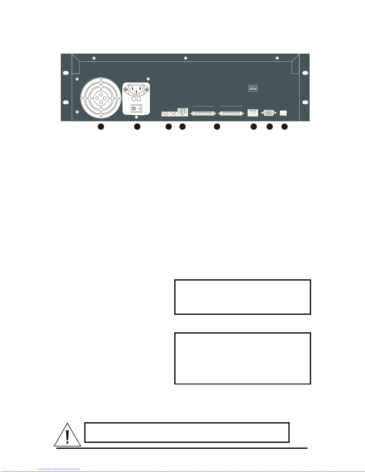
1.4 The Back Panel
ETHERNET
10/100
RELAY
SCSIIEEE-1394 RS-232SW 1
PORT 1PORT 1
OFF
OFF
1234
ON
ON
PORT 2 PORT 2
1: SCSI TERMINATION
2: SCSI POWER
3: BUZZER
4: AUX
1 222 3 4 5 6 7 8
Back Panel Components
1. Cooling Fan: Do not obstruct.
2. Power Connector, Voltage Selector and On/Off Switch.
3. IEEE-1394 Firewire Ports 1 and 2.
4. 10/100 Ethernet Port.
5. SCSI Ports 1 and 2.
6. Dip Switches (SW1).
7. RS-232 Port.
8. Alarm Out Relay Connection (Future feature).
1.5 Connections
10/100 Ethernet Port
The Ethernet port is used to connect
the DVSe into a network
environment.
Wire Type: Cat 5.
Connector Type: RJ-45.
Cable Required: Ethernet.
SCSI Ports 1 and 2
Connect a SCSI device to one of the
two SCSI ports. Set the dip switches
(SW1) on the back panel. Set SCSI
Termination and SCSI Power to On
and use the Bus Select menu option
to enable this feature.
Connector: 50 pin, high density SCSI-2.
Gender (on unit): Female.
SCSI ID: 0.
The unit does not currently support multiple SCSI device connections.
Caution! Ensure the power to DVSe is OFF BEFORE
connectin
g
any SCSI or 1394 devices. Do not attempt to use
DVSe 6 0150-0178H
Page 7
the SCSI and 1394 ports simultaneously.
1394 Firewire Ports 1 and 2
Connect a 1394 Firewire device to
one of the two 1394 ports. Use the
Bus Select menu option to enable
this feature.
Cable: 6 position IEEE 1394.
Connectors: 6 position DIP.
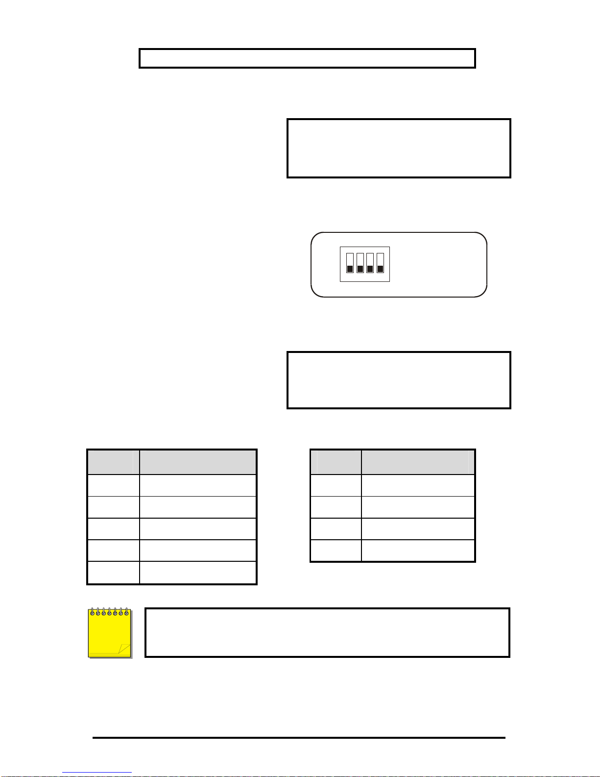
Dip Switches (SW1)
Set the Dip Switches to enable or
disable the features listed on the
illustration to the right. Switch
position up to turn off (disable), down
to turn on (enable).
OFF
1234
ON
1: SCSI TERMINATION
2: SCSI POWER
3: BUZZER
4: AUX
RS-232 Port
The RS-232 port can be used for
Serial Debugging.
Connector Type: DB-9.
Gender (on unit): Male.
Cable Required: Null Modem.
DB-9 Pin Configuration For RS-232 Port
Pin Use Pin Use
1 DCD 6 Not Connected
2 RX 7 RTS
3 TX 8 CTS
4 Not Connected 9 Not Connected
5 Ground
To receive serial debug data from the DVSe’s RS-232 port, set up the
receiving serial port at 57600 bps, No Parity, 8 data bits, and 1 stop
bit.
NOTE
0150-0178H 7 DVSe
Page 8
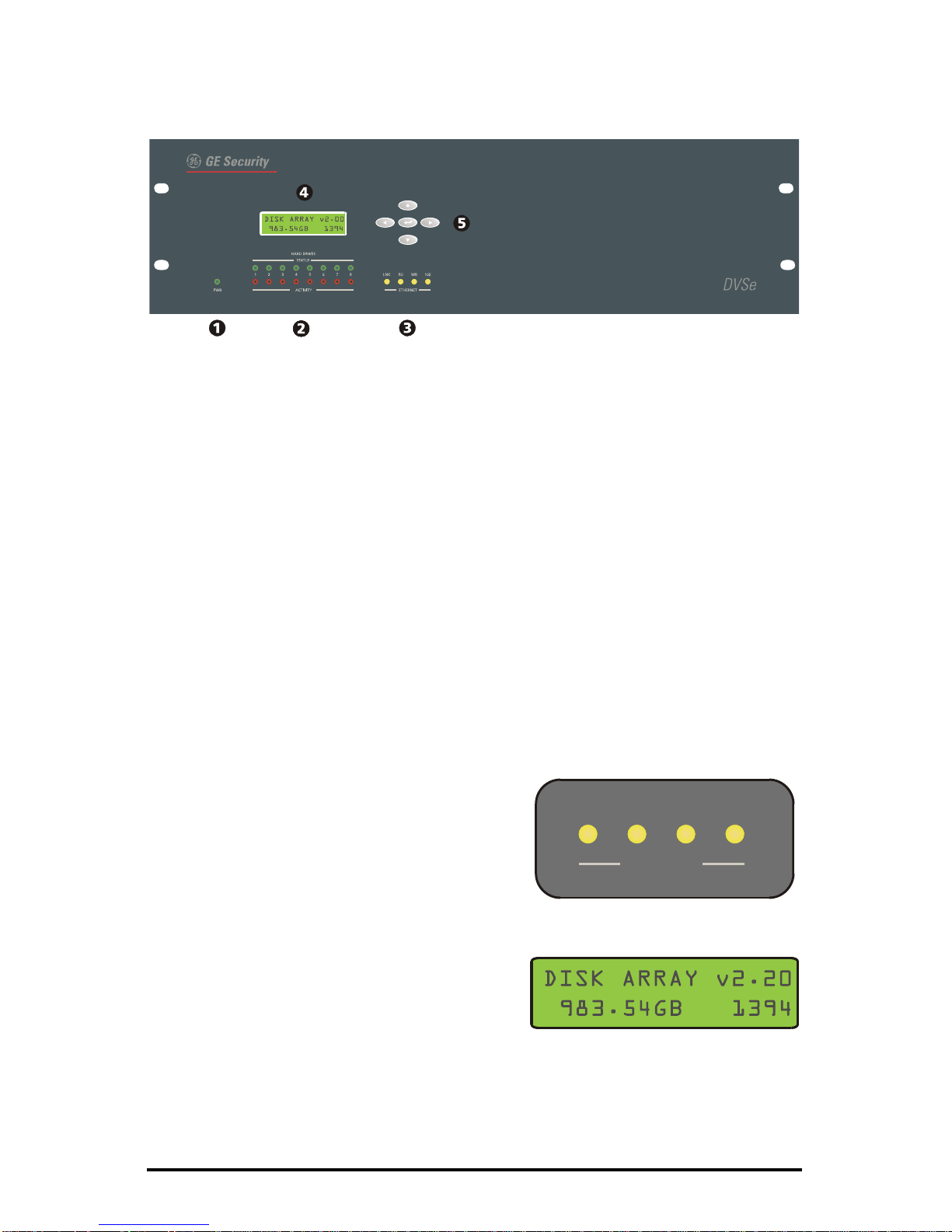
1.6 Front Panel Indicators
1. Power LED.
2. Hard Drive Status Indicators.
3. Ethernet Indicators.
4. LCD Display.
5. Key Pad buttons.
Hard Drive Status Indicators (Green LEDs)
LED On: Drive present and operating normally.
LED Off: No drive present, drive not detected, drive disabled due to error.
Hard Drive Activity Indicators (Red LEDs)
The LED blinks when the drive is being accessed (read or write).
Ethernet Indicators
The ethernet LEDs light to indicate the following:
• Link: A detected ethernet connection.
• RD: Receiving Data.
• WR: Transmitting Data.
• 100: 100 Mbps bandwidth
LNK RD WR 100
ETHERNET
LCD Display
Once power-up is complete, the LCD
displays the total disk storage capacity of the
unit. The LCD display also provides visual
feedback for the menu settings. See DVSe
Menu Setup for details.
DVSe 8 0150-0178H
Page 9

Key Pad
The Key Pad buttons provide access and control of the Setup Menu.
• Up Arrow: Change field data (ascending).
• Left Arrow: Move field selection to left.
• Enter Button: Press to access setup
menu. Toggles through menu screens.
• Right Arrow: Move field selection to right.
• Down Arrow: Change field data
(descending).
0150-0178H 9 DVSe
Page 10

2 Hard Drive Installation
This section contains important information on adding or replacing the internal
Disk Drives. Please read the entire section before performing any work.
Caution: Do not allow any metal object to contact the
motherboard. Do not allow loose screws to become lost inside
the DVSe chassis. Wear an Electro Static Discharge protection
device any time work is being performed inside the unit.
2.1 Opening The DVSe
Before removing the cover, turn off the unit and unplug it. Using a Phillips-head
screwdriver, carefully remove the twelve screws fastening the lid to the chassis.
Save the screws and use them to refasten the lid when finished.
2.2 Identifying The Components
Complete Internal Overview
Mother
Board
Disk Drives
Power
Supply
Drive Support Bracket
DVSe 10 0150-0178H
Page 11

Motherboard Overview
IDE Power
Connectors
IDE
Connectors
Power
Supply
Load
Resistors
Jumpers
2.3 Compatible Hard Drives
The DVSe is designed to be compatible with Maxtor D540X and MaXLine II
series of hard drives. Hard drives in this series up to 250 GB may be used.
Refer to www.maxtor.com for details.
Hard Drives must be added in pairs and must be of the same type,
speed, and capacity.
GE Security cannot provide technical support for DVSe units using
hard drives other than those described above. Using drives other
than those described above may result in failure or intermitt ent data
errors.
NOTE
Please contact GE Security Technical Support regarding hard disk compatibility.
0150-0178H 11 DVSe
Page 12

2.4 Configuring the Hard Drives
Hard drives are connected in pairs
to each of the four IDE
connectors. Each pair of hard
drives must be configured as a
Master and a Slave. Configure
the Master/Slave settings on each
hard drive individually using the
jumpers provided with the drive.
Use the diagram located on the
hard drive to determine the proper
jumper configuration.
2.5 Mounting The Hard Drives
Remove the Hard Drive Support Bracket. This entails removing the screws at
either end and one screw from each installed hard drive.
Orient the hard drive so that the IDE Power Connector is near the bottom of the
chassis and facing the motherboard. Populate the drive array in order, starting
from the left.
Fasten the drive in place using the supplied screws. Fasten each drive using two
screws through the bottom of the chassis and one screw in the Hard Drive
Support Bracket.
2.6 Connecting the Hard Drives
Power Supply Cables
It is recommended, for ease of installation, that the IDE and power
cables be first connected to the drives before the drive screws are
tightened.
NOTE
DVSe 12 0150-0178H
Page 13

Connect the hard
drives to the power
supply connectors
with power supply
cables.
When connecting a
single drive to a
cable, attach the
drive to the
connector at the end
of the power cable.
Disk 1
Disk 2
Disk 3
Disk 4
Disk 5
Disk 6
Disk 7
Disk 8
Power Supply
Mother Board
NOTE
The diagram above shows a typical connection. The connections
may vary according to the number of drives in the system and the
power cable type.
IDE Data Cables
Use an IDE cable to connect the drives as shown in the diagram in section 2.3.
When attaching the IDE connector, make sure the connectors are oriented
properly.
Connecting To The Motherboard
The red stripe on the connection ribbon
should connect nearest the Pin 1 indicator
on the motherboard.
Pin 1
Indicator
Connecting To The Hard Drive
The red stripe on the connection ribbon
should connect near the jumpers on the hard
drive.
Pin 1 Near
Jumpers
0150-0178H 13 DVSe
Page 14

2.7 Jumper Settings
Jumper Configuration
Configure the jumpers based on the number of hard drives installed in the unit.
Do not throw away unused jumpers.
See section 2.2 to locate this block of jumpers.
2-6 Drives 8 Drives
Load 4
Load 3
Load 2
Load 1
Load 4
Load 3
Load 2
Load 1
After any drives are installed, replaced or removed, the Reset Disk
Failure command must be run from the Supervisor Menu for the
changes to be recognized by the DVSe.
NOTE
DVSe 14 0150-0178H
Page 15

3 DVSe Setup
This section contains important information on setting up the DVSe for
operation. Please read the entire section before performing any work.
3.1 Connecting by SCSI or 1394
Caution! The DVSe does NOT support the simultaneous use
of the SCSI and 1394 ports. Only connect one type of device at
a time.
SCSI
Connect a SCSI device to one of the two SCSI ports using the supplied SCSI
cable. Set the dip switches (SW1) on the back panel. Set SCSI Termination
and SCSI Power to On. Select SCSI as the type of Bus in the Setup Menu
under Bus Select.
Caution! Power must be shut down before connecting SCSI
cables between SCSI devices and the DVSe.
Dip Switches (SW1)
Set the Dip Switches to enable or
disable the features listed on the
illustration to the right. Switch
position up to turn off (disable), down
to turn on (enable).
OFF
1234
ON
1: SCSI TERMINATION
2: SCSI POWER
3: BUZZER
4: AUX
1394 Firewire
Connect a 1394 device to one of the two 1394 ports using the supplied 1394
cable. Set the dip switches (SW1) on the back panel. Set SCSI Termination
and SCSI Power to OFF. Select 1394 as the type of Bus in the Setup Menu
under Bus Select.
Caution! Power must be shut down to all devices before
connecting 1394 cables between the 1394 dev ice and the
DVSe.
0150-0178H 15 DVSe
Page 16

3.2 Power-Up
Select the correct voltage before supplying power to the unit. Use the voltage
selector switch located on the back panel of the unit, between the power
connector and the On/Off Switch.
Caution! Applying incorrect voltage will damage unit.
Once the correct voltage has been selected and all connections have been
made, connect the power cable suited to your geographic location. Apply power
to the unit.
3.3 Setup Menu
The Setup menu provides setup options for the following features:
• Ethernet enable/disable.
• Bus Select: SCSI/1394
• Auto Delete Mode.
• IP Address.
• Subnet Mask Address.
• Default Gateway Address.
• Date/Time Setup.
Menus will automatically be exited after 30 seconds of inactivity.
NOTE
Access to menu is only allowed when the DVSe is Offline, i.e. the
DVSe is not presently archiving or connected via ethernet.
NOTE
Press the Enter Button to access the first menu.
Ethernet Enable
Select ethernet enable, yes or no. Default
setting is no.
Bus Select
Select from SCSI or 1394 to enable. Default
setting is 1394.
DVSe 16 0150-0178H
Page 17

Auto Delete Mode
Auto Delete Mode, select yes or no. Default
setting is no. Auto Delete Mode
automatically invalidates data that is over 30
days old.
Obtain the required network parameters from you Network
Administrator.
NOTE
NOTE
The DVSe will automatically reboot if any of the Bus or Network
parameters are changed.
IP Address
Enter the assigned IP address by using the
left/right arrows to select the field and the
up/down arrows to change the values.
Subnet Mask
Enter the assigned Subnet Mask address by
using the left/right arrows to select the field
and the up/down arrows to change the
values.
Default Gateway
Enter the assigned Default Gateway address
by using the left/right arrows to select the
field and the up/down arrows to change the
values.
Date/Time
Enter the current date and time by using the
left/right arrows to select the field and the
up/down arrows to change the values.
Required only when Auto Delete Mode is set
to yes.
0150-0178H 17 DVSe
Page 18

3.4 Supervisor Menus
The Supervisor menus provides advanced options for the following features:
• Disk Status.
• Reset Disk Failure.
• Serial Debug Output.
The Key Pad buttons provides access and control of the Supervisor Menus. To
access the Supervisor menus press the left and right arrows simultaneously.
• Up Arrow: Quits the menu.
• Left Arrow: Move field selection to left.
• Enter Button: Press to access setup
menu. Toggles through menu screens.
• Right Arrow: Move field selection to right.
• Down Arrow: Quits the menu.
Disk Status
This menu indicates the current disk status.
Disk status is viewable only on this display.
• N: Normal
• W: Error writing to Disk
• R: Error Reading Disk
• T: Timeout during disk initialization or disk
absent
• E: Fails Disk Test
The letters on the Disk Status screen represent Disk 1 (left) thru Disk 8 (right).
NOTE
Do not attempt to reset a disk with read/write errors (a R or W
status). This could lead to more disk errors and data loss. Disks
with read/write errors should be replaced.
NOTE
Disks with a T status may be recovered, but the DVSe will
attempt to start recording to this disk. A recovery should not be
attempted until the preceding disk is filled up. Contact Technical
Support for detailed instructions on replacing or recovering
problem hard disks.
DVSe 18 0150-0178H
Page 19

NOTE
Be sure to confirm that the drives are connected according to the
diagram in Section 2.3 before removing or replacing. The disk
status display and LEDs represent the wiring and Master/Slave
configuration, not the physical location of the drives.
Reset Disk Failure
This command allows the DVSe to re-enable
disks with timeout errors and reset the Disk
Status. Changing this setting restart the unit.
Any time that a disk is replaced, added, or
removed this command must be executed.
Serial Debug
Serial Debug output, select yes or no.
Default setting is no. Enabling serial debug
will output debug messages on the RS232
port at 57600 bps. Changing this setting will
cause the unit to restart.
3.5 Hard Disk Test
Two types of Hard Disk Test are accessible via the front panel:
• The Quick Disk Test: This test takes approximately 5 minutes.
• The Burn In Disk Test: This test can run over 8 hours
depending on the size of the Hard Disks.
The Quick Disk Test
The Quick Disk Test is accessible by
simultaneously pressing the UP and Down
Arrow buttons. This test performs random
read and writes on all the disks. See the
flow chart on the following page for detailed
information.
The Burn In Disk Test
The Burn In Disk Test is accessible by
selecting No on the Quick Disk Test Screen
and pressing the Enter button. This test
performs sequential read and writes on all
the disks and is a much more
comprehensive. See the flow chart on the
following page for detailed information.
0150-0178H 19 DVSe
Page 20

Both Tests may be cancelled by depressing the UP Arrow Button
until the test stops.
NOTE
Caution! Do not run any SCSI, Ethernet, or Firewire Operation
while performing either Disk Test. Permanent damage to the
DVSe may occur.
3.6 Upgrading the DVSe
Upgrading the software for the DVSe is accomplished via the ethernet port
and a PC/Laptop equipped with a web browser.
To properly upgrade the GE Security DVSe the following preconditions mu st
exist:
DVSe 20 0150-0178H
Page 21

1. The Flash upgrade file and path. This file is obtained by calling GE
Security Technical Support at 1-800-469-1676. When calling, pleas e
have the following information available:
T he model number of the product.
T he serial number and revision of the product
T he current firmware version.
The date purchased.
Symptoms of the unit that might require u pgrade.
2. The DVSe unit connected to a PC equipped with Microsoft Internet
Explorer version 5.5 or later via ethernet cable.
3. The IP address of the DVSe.
4. WaveReader software must NOT be connected to the DVSe. Please
exit all non-essential software on the PC.
5. Ensure that the DVSe is not currently recording or archiving.
Follow the steps below to Upgrade the DVSe:
Step 1. Launch the Browser software (Microsoft Internet Explorer 5.5 or
later).
Step 2. Enter the IP address of the DVSe in the address field of the Browser
followed by /upgrade.ssi and press enter. For example if the IP
address is 3.18.173.71 type 3.18.173.71/upgrade.ssi.
Step 3. The Enter Network Password window should appear. Enter the
correct Username and Password in their respective fields. (The
default username is admin and the password is admin. It is
recommended that the defaults be changed ASAP). Click the OK
button. The DVSe upgrade page should appear.
0150-0178H 21 DVSe
Page 22

Step 4. Navigate to the upgrade file using the Browse button or type in the
correct path and filename. Click on the Send File button.
Step 5. Click on the Confirm Button. A progress bar will appear. PLEASE
WAIT FOR THE PROGRESS BAR TO FINISH, THEN WAIT FOR
CONFIRMATION!
Step 6. Click on the Reboot button to restart the unit for changes to take
effect. If unsuccessful, download the flash file again and retry the
steps 1-6.
DVSe 22 0150-0178H
Page 23

4 Warranty and Service
4.1 Factory Service
If the unit requires factory service, contact the dealer who supplied the unit to you
for the correct procedures on returning the unit to the factory or the nearest
factory service center.
If the dealer is not available, contact the manufacturer of the unit as detailed
below and request a Return Material Authorization number (RMA). The unit’s
serial number must be provided before an RMA number can be issued. Units
returned to the factory for service must have freight and insurance prepaid, and
must show the RMA number clearly on all shipping documents. The failure
symptoms must be clearly described by the operator and enclosed with the unit
together with a copy of the original supplier’s invoice. Failure to comply with
these instructions will delay service of the unit, and may result in the unit not
being accepted by the Repair Center.
4.2 Factory Address
GE Security
Attention: Repair Center
3050 Red Hill Ave.
Costa Mesa, CA 92626
United States of America
Telephone: 800-343-3358 (7:00 AM to 4:30 PM, Pacific Time)
In Oregon: 541-754-9133
Fax: 541-754-7162 (24 hours a day)
For warranty information, see the following page.
4.3 Warranty
GE Security warrants all of its equipment for three years from the date of
purchase. This warranty covers any defects in materials and workmanship.
Equipment failures that are due to improper installation, modification, abuse, or
acts of nature will not be covered by this warranty. The repair department will
evaluate all equipment returned for repair to determine warranty coverage. The
Tech Support Manager will resolve any questions that may arise during
evaluation to make a final determination.
Note: The three-year warranty does not apply to the following products:
MobileView
®
and the monitor CRT, which carry a 12-month warranty from the date of
purchase.
The warranty specifically covers any defects in material and workmanship and
does not cover equipment that has been abused, damaged, or modified.
For all warranty repairs, GE Security will cover all costs, including parts, labor,
and shipping. Repaired equipment will be returned via the same method of
0150-0178F 23 DVSe
Page 24

shipment in which it was received. If a customer requests a faster return
shipment, the difference will be charged.
For all non-warranty repairs, the customer will be billed for parts, labor, and
shipping. Labor will be billed in half-hour increments.
Note: Customers requesting an estimate prior to repair will be notified by phone. If they
cannot be reached, they will be notified by fax. If we are unable to reach the contact person
for repair authorization after one phone attempt and two fax attempts, the equipment will be
returned without being repaired. We will hold equipment no longer than two weeks.
Advance Replacement Policy
When an advance replacement is required, we will send the customer
replacement equipment from our stock and receive the returned product in
exchange. The received equipment will be evaluated a nd the repair department
will determine whether it is a warranty replacement. If it is non-warranty, see our
repair policy above for details. The following guidelines will be used for all
advance replacements:
• Fewer than 45 days from purchase, GE Security will replace the product with new
equipment.
• From 45 days to 1 year from purchase, GE Security will replace the product with
refurbished equipment.
• From 1 year to 3 years from purchase, the product must be sent in for repair.
Advance replacements will be sent for a fee of $100.
If you have questions about this policy, please contact GE Security’s RMA
Department at
800-469-1676.
DVSe 24 0150-0178H
 Loading...