

Page 1
GE Digital Energy
Power Quality
Operating Manual
Uninterruptible Power supply
Digital Energy™
LP 33U Series
50 & 60 kVA
208 VAC UL / Series 1
GE Consumer & Industrial SA
General Electric Company
CH – 6595 Riazzino (Locarno)
Switzerland
T +41 (0)91 / 850 51 51
F +41 (0)91 / 850 51 44
www.gedigitalenergy.com
GE imagination at work
Page 2

Modifications reserved Page 2/65
OPM_LPS_3UO_50K_60K_1US_V010.doc Operating Manual LP 33U Series 30 & 40 kVA
Model:
LP 33U Series / 50 & 60 kVA / Series 1
Date of issue: 08/15/2008
File name: OPM_LPS_3UO_50K_60K_1US_V010
Revision: 1.0
Identification No.
Up-dating
Revision Concerns Date
COPYRIGHT © 2008 by GE Consumer & Industrial SA
All rights reserved.
The information contained in this publication is intended solely for the purposes indicated.
The present publication and any other documentation supplied with the UPS system is not to be
reproduced, either in part or in its entirety, without the prior written consent of GE.
The illustrations and plans describing the equipment are intended as general reference only and are
not necessarily complete in every detail.
The content of this publication may be subject to modification without prior notice.
Page 3
Modifications reserved Page 3/65
OPM_LPS_3UO_50K_60K_1US_V010.doc Operating Manual LP 33U Series 30 & 40 kVA
Dear Customer,
We thank you for selecting our products and are
pleased to count you amongst our very valued
customers at GE.
We trust that the use of the LP 33U Series
Uninterruptible Power Supply system, developed
and produced to the highest standards of quality,
will give you complete satisfaction.
Please carefully read the Installation Guide.
It contains all the necessary information about the
installation of the UPS.
Thank you for choosing GE !
START UP AND COMMISSIONING
A GE Global Services Field Engineer must perform start-up and
commissioning of the UPS. Please Contact GE. Global Services at least two
weeks prior to schedule start-up and commissioning at 1-800-637-1738, or
by E-mail at pqservices@ge.com
Sold in the North America by:
Your service contact:
g
GE Consumer & Industrial SA
General Electric Company
CH – 6595 Riazzino (Locarno)
Switzerland
www.gedigitalenergy.com
g
GE Digital Energy
Power Quality
2501 Pecan Street
Bonham, TX 75418
T: +1 800-637-1738
F: +1 903-640-0533
E: GEPQSales@ge.com
http://www.gedigitalenergy.com/ups
Page 4
Modifications reserved Page 4/65
OPM_LPS_3UO_50K_60K_1US_V010.doc Operating Manual LP 33U Series 30 & 40 kVA
Preface
Congratulations on your choice of a LP 33U Series Uninterruptible Power Supply (UPS).
It will help eliminate load disturbances due to unexpected power problem.
This Installation Guide describes how to prepare the installation site, and it provides
weight and dimensions and procedures for moving, installing and connecting the UPS.
While every care has been taken to ensure the completeness and accuracy of this manual,
GE assumes no responsibility or liability for any losses or damages resulting from the use
of the information contained in this document.
WARNING !
LP 33U Series / 50 & 60 kVA , is a product that needs to be installed by a licensed and
knowledgeable contractor.
We recommend that this manual be kept next to the UPS for future references.
If any problems are encountered with the procedures contained in this manual, please
contact your Service Center before you proceed.
This document shall not be copied or reproduced without the permission of GE.
Some of the information contained in this manual may be changed without notice to
reflect technical improvements.
Safety instructions
Read the safety instructions contained on the following pages carefully before the
installation of the UPS, options and battery system.
Pay attention to the rectangular boxes included in the text:
They contain important information and warning concerning electrical connections and
personnel safety.
Parallel version secured with RPA
When included in the text, this symbol refers to operation needed
only for parallel system.
Page 5

Modifications reserved Page 5/65
OPM_LPS_3UO_50K_60K_1US_V010.doc Operating Manual LP 33U Series 30 & 40 kVA
Table of contents Page
1 SAFETY RULES................................................................................................................................................ 6
2 LAYOUT........................................................................................................................................................... 9
2.1 LAYOUT LP 33U Series / 50 & 60 KVA...........................................................................................................................................9
3 INTRODUCTION........................................................................................................................................... 11
3.1 GENERAL DESCRIPTION................................................................................................................................................................... 11
4 DESCRIPTION............................................................................................................................................... 12
4.1 BLOCK DIAGRAM AND MAIN ELEMENTS DESCRIPTION.................................................................................................... 12
4.2 OPERATION MODES........................................................................................................................................................................... 13
4.3 RPA PARALLEL SYSTEM.................................................................................................................................................................... 16
4.4 UPS PARALLELED ON THE SAME BATTERY.............................................................................................................................. 17
4.5 SERVICE AND TECHNICAL SUPPORT.......................................................................................................................................... 18
4.6 RECYCLING AT THE END OF SERVICE LIFE .............................................................................................................................. 19
5 SYSTEM HANDLING..................................................................................................................................... 20
5.1 CONTROL PANEL ................................................................................................................................................................................ 20
5.2 TABLE OF FUNCTIONS AND INDICATIONS ON CONTROL PANEL.................................................................................. 21
5.3 SWITCHES.............................................................................................................................................................................................. 23
6 LCD SCREEN................................................................................................................................................. 24
6.1 HOME SCREEN..................................................................................................................................................................................... 24
6.2 METERING.............................................................................................................................................................................................. 26
6.3 ALARMS .................................................................................................................................................................................................. 28
6.3.1 Events (alarms and messages).......................................................................................................................................................... 29
6.3.2 Alarms list.................................................................................................................................................................................................... 29
6.3.3 Messages list.............................................................................................................................................................................................. 32
6.3.4 Event report LP 33U Series................................................................................................................................................................... 34
6.4 SETUP ......................................................................................................................................................................................................35
6.5 COMMANDS.......................................................................................................................................................................................... 40
7 OPERATION.................................................................................................................................................. 41
7.1 PROCEDURES FOR SINGLE LP 33U Series ............................................................................................................................... 41
7.1.1 Start-up of the LP 33U Series.............................................................................................................................................................. 41
7.1.2 UPS shutdown with load transfer on manual bypass (Q2)................................................................................................... 45
7.1.3 From Manual Bypass Q2 to normal function VFI...................................................................................................................... 47
7.1.4 Complete UPS shutdown...................................................................................................................................................................... 48
7.1.5 Restore to normal operation after “Total Off”............................................................................................................................. 49
7.1.6 Restore to normal operation after “EPO – Emergency Power Off”.................................................................................... 50
7.2 PROCEDURES FOR LP 33U Series PARALLEL SYSTEM........................................................................................................ 51
7.2.1 LP 33U Series Parallel System start-up........................................................................................................................................... 51
7.2.2 Parallel UPS shutdown with load transfer on manual bypass (Q2)................................................................................... 55
7.2.3 From Manual Bypass Q2 to normal function VFI...................................................................................................................... 57
7.2.4 Separate (shutdown) a UPS unit from the Parallel System (System Redundancy).................................................... 58
7.2.5 Reconnect a UPS unit to a Parallel System.................................................................................................................................. 59
7.2.6 Complete Parallel System shutdown.............................................................................................................................................. 60
7.2.7 Restore to normal operation after “Total Off”............................................................................................................................. 61
7.2.8 Restore to normal operation after “EPO – Emergency Power Off”.................................................................................... 62
8 OPTIONS....................................................................................................................................................... 63
8.1 OPTIONS GENERAL VIEW................................................................................................................................................................ 63
9 MAINTENANCE ............................................................................................................................................ 64
9.1 GENERAL MAINTENANCE................................................................................................................................................................ 64
9.2 COOLING FAN MAINTENANCE...................................................................................................................................................... 64
9.3 BATTERY MAINTENANCE................................................................................................................................................................. 64
9.4 SERVICE REQUIRED ...........................................................................................................................................................................64
10 NOTES ........................................................................................................................................................... 65
10.1 NOTES FORM........................................................................................................................................................................................ 65
Page 6
Modifications reserved Page 6/65
OPM_LPS_3UO_50K_60K_1US_V010.doc Operating Manual LP 33U Series 30 & 40 kVA
1 SAFETY RULES
With this document, GE gives all the necessary information about the correct use of the UPS to the user.
We recommend that this manual be kept next to the UPS for future references.
If any problems are encountered with the procedures contained in this manual, please contact the
nearest Service Center before you proceed.
All UPS installation, maintenance and service work should be performed by qualified service personnel
only.
The KNOWLEDGE and the FULLY compliance of the safety instructions and
the warning contained in this manual are
THE ONLY CONDITION
to avoid any dangerous situations during installation, operation,
maintenance work, and to preserve the maximum reliability of the UPS
system.
NOTE !
LP 33U Series / 50 & 60 kVA is a FCC Class A-UPS Product.
While every care has been taken to ensure the completeness
and accuracy of this manual, GE assumes no responsibility or
liability for any losses or damages resulting from the use of the
information contained in this document.
GE
Refuses any responsibility in case of non-observance,
unauthorized alterations or improper use of the delivered UPS.
Page 7

Modifications reserved Page 7/65
OPM_LPS_3UO_50K_60K_1US_V010.doc Operating Manual LP 33U Series 30 & 40 kVA
SAVE THESE INSTRUCTIONS
This manual contains important instructions for models LP 33U Series / 50 & 60 kVA that should
be followed during installation and maintenance of the UPS and battery.
GENERAL
- Move the UPS in an upright position in its original package to the final destination
room.
- Check for sufficient floor and elevator loading capacity.
- Check the integrity of the UPS equipment carefully.
If you notice visible damage, do not install or start the UPS. Contact the nearest Service
Center immediately.
- WARNING! RISK OF ELECTRICAL SHOCK: Do not remove covers; there are no user
serviceable parts inside.
- After switching off takes 5 minutes for the DC capacitors to discharge because a
lethally high voltage remains at the terminals of the electrolytic capacitors.
- All maintenance and service work should be performed by qualified service personnel.
The UPS contains its own energy source (battery).
- The field-wiring terminals may be electrically live, even when the UPS is disconnected
from the utility.
- Dangerous voltages may be present during battery operation.
The battery must be disconnected during maintenance or service work.
- This UPS contains potentially hazardous voltages.
- Be aware that the inverter can restart automatically after the utility voltage is restored.
STORAGE
- Store the UPS in a dry location; storage temperature must be within -13°F (-25°C) to
131°F (55°C).
- If the unit is stored for a period exceeding 3 months, the battery must be recharged
periodically (time depending on storage temperature).
BATTERY
- The battery-voltage is dangerous for person’s safety.
- When replacing the battery, use the same cells number, voltage (V), capacity (Ah).
All the battery used, shall be of the same manufacturer and date of production.
- Proper disposal or recycling of the battery is required.
Refer to your local codes for disposal requirements.
- Never dispose of battery in a fire: They may explode.
- Do not open or mutilate battery: Their contents (electrolyte) may be extremely toxic.
If exposed to electrolyte, wash immediately with plenty of water.
- Avoid charging in a sealed container.
- Never short circuit battery. When working with battery, remove watches, rings or other
metal objects, and only use insulated tools.
- In case of air shipment, the cables +/- going to the battery fuses/terminals shall be
disconnected and isolated.
Page 8
Modifications reserved Page 8/65
OPM_LPS_3UO_50K_60K_1US_V010.doc Operating Manual LP 33U Series 30 & 40 kVA
Safety symbols and warnings
Safety warnings
The text of this manual contains some warnings to avoid risk to the persons and to avoid damages to
the UPS system and the supplied critical loads.
The non-observance of the warnings reminding hazardous situations could result in human injury and
equipment damages.
Please pay attention to the meaning of the following warnings and symbols.
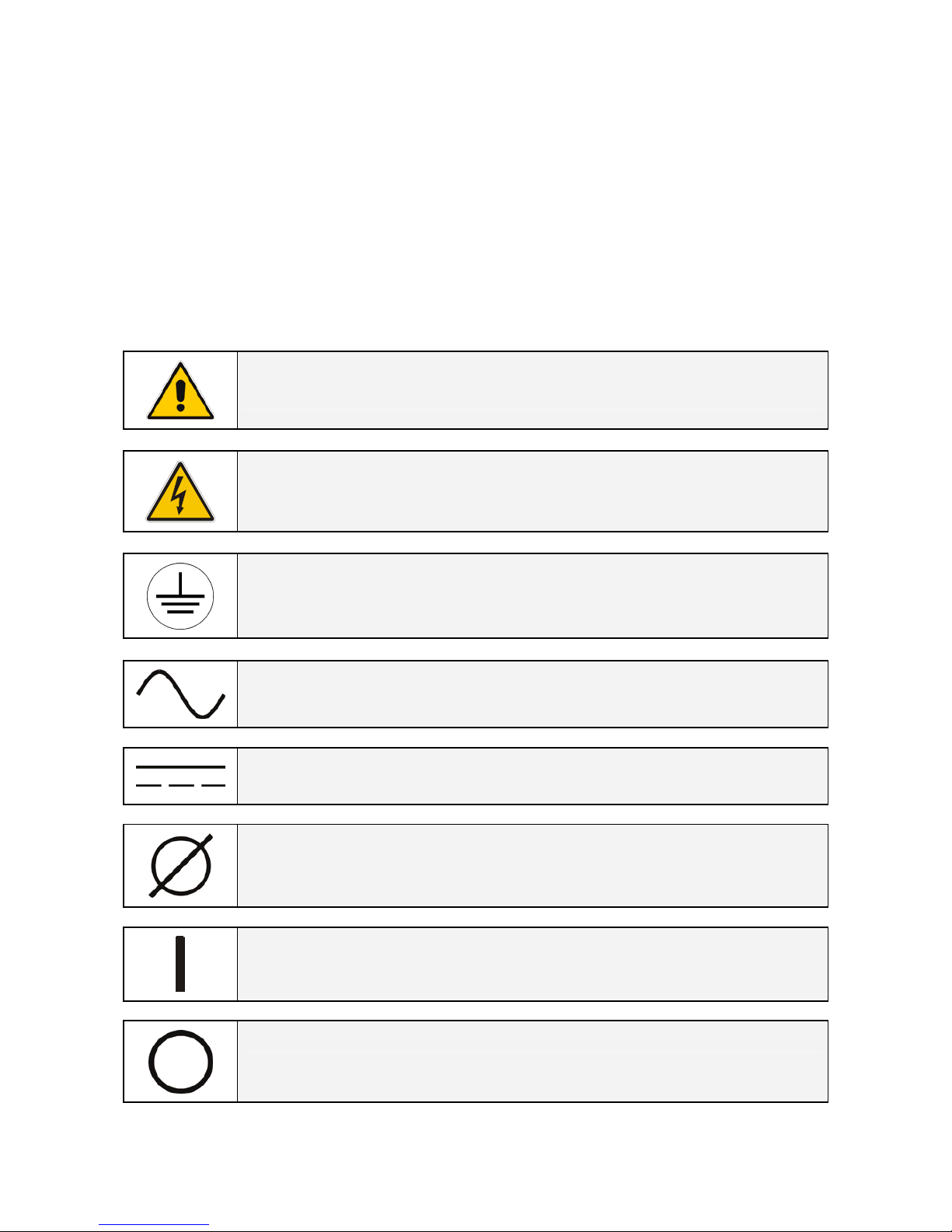
Throughout this manual the following symbols are defined:
WARNING, if instruction is not followed injury or serious equipment damage may
occur!
CAUTION, internal parts have dangerous voltage present.
Risk of electric shock!
PE (Earth) – GND (Ground)
PROTECTIVE GROUNDING TERMINAL:
A terminal which must be connected to earth ground prior to making any other
connection to the equipment.
A terminal to which or from which an alternating (sine wave) current or voltage
may be applied or supplied.
A terminal to which or from which a direct current or voltage may be applied or
supplied.
This symbol indicated the word “phase”.
This symbol indicates the principal on/off switch in the on position.
This symbol indicates the principal on/off switch in the off position.
Page 9
Modifications reserved Page 9/65
OPM_LPS_3UO_50K_60K_1US_V010.doc Operating Manual LP 33U Series 30 & 40 kVA
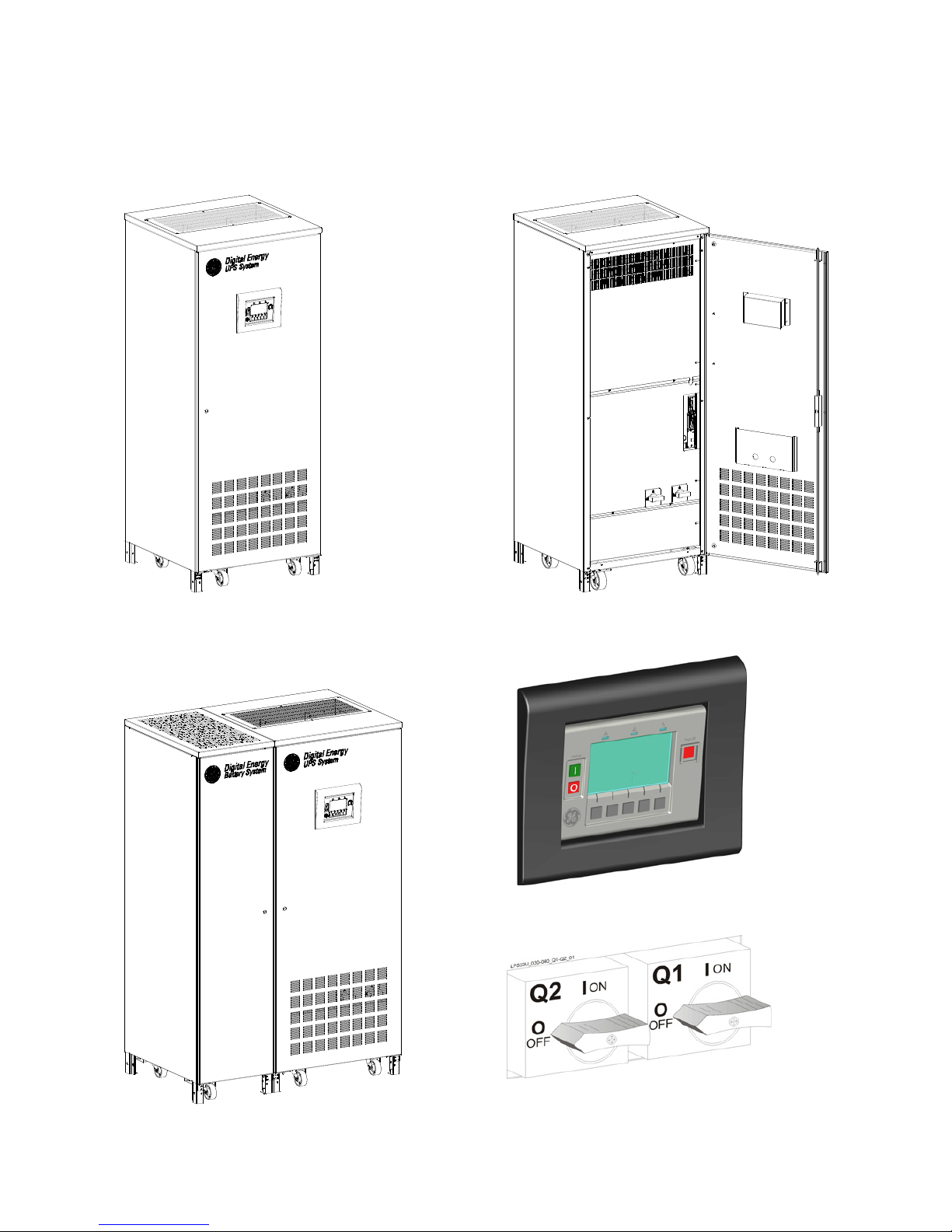
2 LAYOUT
2.1 LAYOUT LP 33U Series / 50 & 60 kVA
Fig. 2.1-1 General view – UPS only Fig. 2.1-2 General view – UPS only - with front door open
Fig. 2.1-4 Control panel
Fig. 2.1-3 General view – UPS with Battery Cabinet
Fig. 2.1-5 Q1 & Q2 switches
Page 10
Modifications reserved Page 10/65
OPM_LPS_3UO_50K_60K_1US_V010.doc Operating Manual LP 33U Series 30 & 40 kVA
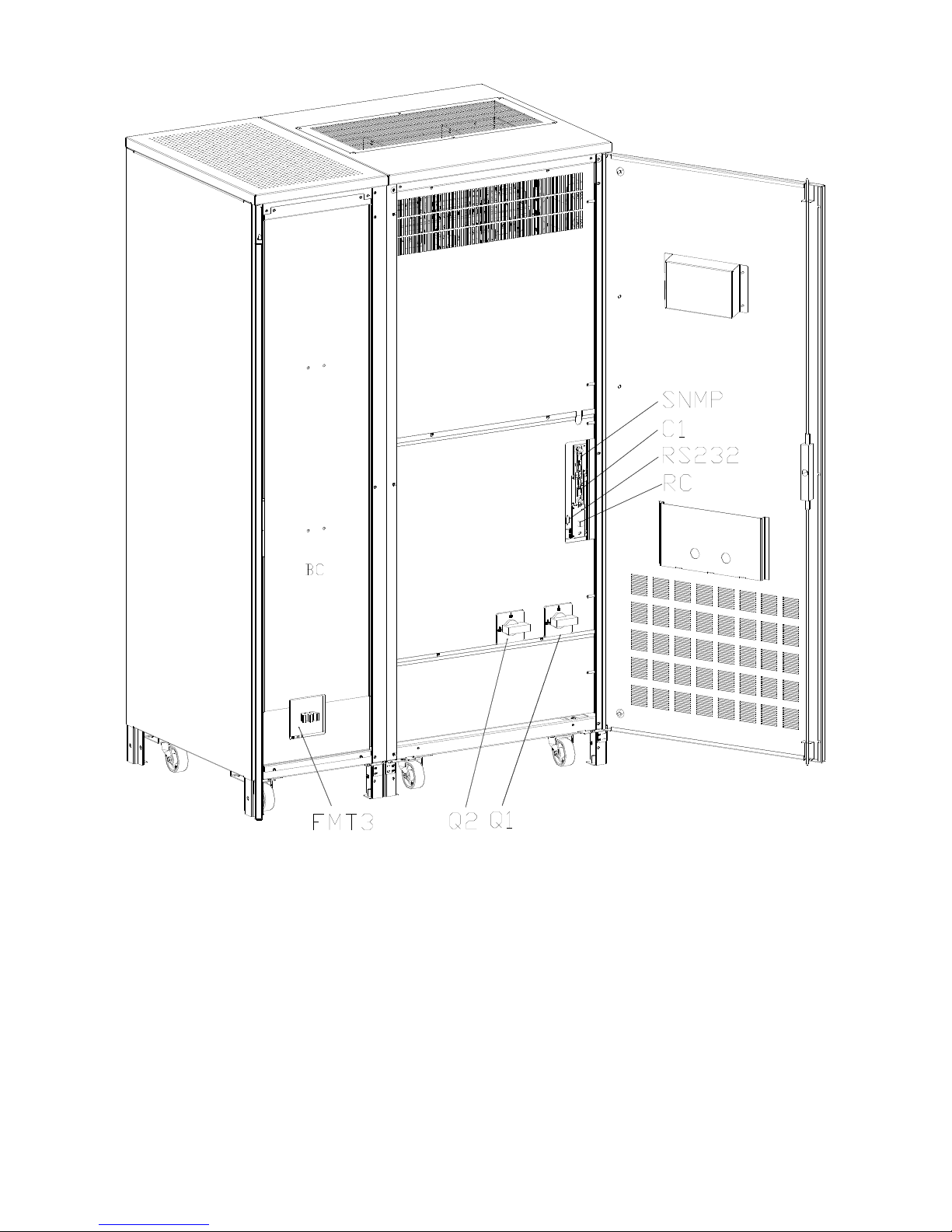
Fig. 2.1-6 General view with open door – UPS with Battery Cabinet
BC Battery cabinet
CI Customer Interface Board (optional)
FTM3 Battery Breaker
Q1 UPS output switch
Q2 Manual bypass switch
RC Relay card
SNMP Advanced SNMP Card (optional)
RS232 Serial port RS232
Page 11

Modifications reserved Page 11/65
OPM_LPS_3UO_50K_60K_1US_V010.doc Operating Manual LP 33U Series 30 & 40 kVA
3 INTRODUCTION
3.1 GENERAL DESCRIPTION
The LP 33U Series Uninterruptible Power Supply (UPS) provides the energy supply for critical loads
which need a reliable, continuous, and free from ‘voltage disturbances and frequency fluctuations’
supply.
In case the utility fails, or it exceeds the permitted tolerances, the energy to supply the load is furnished
by the battery with a backup time dependent on its capacity, until the utility recovers.
LP 33U Series is a truly VFI double conversion Uninterruptible Power Supply (UPS),
equipped with automatic bypass, where the load is normally supplied by the inverter.
LP 33U Series can be configured, if chosen, for the ECO Mode permitting the maximum
energy saving.
The main typical performances of the LP 33U Series system are the following:
• VFI (Voltage Frequency Independent) double conversion technology to provide an excellent
quality power supply.
• Input power factor >0.98.
• Input current THD <10%.
• Automatic bypass and manual bypass to improve reliability and maintenance.
• Microprocessor controlled supervision.
• Dual AC inputs (optional).
• ECO Mode operation.
• Compact and agreeable design expressly conceived for “Office environment”.
• Low level acoustic sound, 65 dB (A) (50 & 60 kVA) to avoid noise to the persons operating in the
same environment.
• Multi-language LCD screen.
• Total battery management: SBM (Superior Battery Management)
• High battery capacity, 9 minutes (50 kVA) and 8 minutes (60 kVA), with battery housed in the
UPS cabinet.
• Wide rectifier input voltage tolerance: 177 - 229 VAC (Line-Line).
• Wide rectifier input frequency tolerance: +/-10% (54 - 66 for 60 Hz).
• RPA (Redundant Parallel Architecture) up to 4 units.
• GE Connectivity.
• Compliance with UL standard 1778.
Page 12
Modifications reserved Page 12/65
OPM_LPS_3UO_50K_60K_1US_V010.doc Operating Manual LP 33U Series 30 & 40 kVA
4 DESCRIPTION
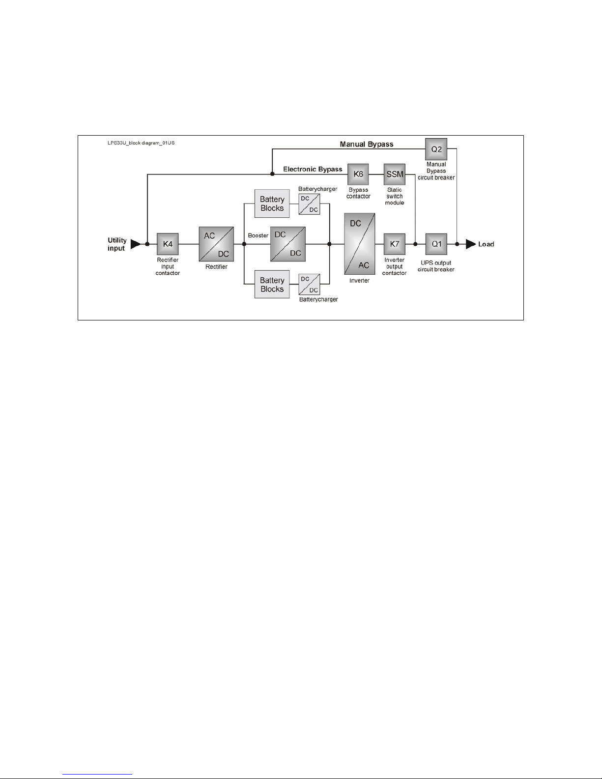
4.1 BLOCK DIAGRAM AND MAIN ELEMENTS DESCRIPTION
Fig. 4.1-1 UPS block diagram
The Uninterruptible Power Supply System LP 33U Series / 50 & 60 kVA can be divided into the following
main elements:
Electronics
The UPS is designed with a microprocessor–controlled supervision and diagnostic system.
Communication between user and UPS is achieved by the front panel consisting of an LCD screen,
displaying the operation modes, the measurements and the events / alarms.
Rectifier
The rectifier converts the 3-phase mains voltage into a controlled and regulated DC-voltage, in order to
supply power to the booster, and to charge the battery through the battery-charger.
Inverter
The inverter converts the DC voltage into a three-phase AC-voltage with constant amplitude and
frequency, which is completely independent from the AC-input voltage.
Automatic Bypass
The automatic bypass consists of a static semiconductor-switch (SSR: Static Switch Relay), used to
provide an uninterrupted transfer of the load from inverter to mains when operating in VFI Mode.
If chosen the ECO Mode, the SSM transfer the load from mains to inverter in case the utility fails.
Back-Feed Protection
All LP 33U Series UPS’s are equipped with an automatic system for the protection against voltage back
feeding towards Utility, through the Bypass (Applied Standard IEC 62040-1).
This protection works automatically by opening contactor K6 (in series with the thyristors of the static
switch) and eventually K7, and acts in case of internal defects of the system, or due to wrong
manipulations on the maintenance bypass Q2.
Manual Bypass
The manual bypass consists of a pair of manual switches Q1 and Q2, which allow the isolation of the
UPS from the load, while still supplying the load with power directly from the mains.
Battery
The battery, normally stored by the battery-charger, supplies the DC energy to inverter in the event of
mains failure.
Page 13
Modifications reserved Page 13/65
OPM_LPS_3UO_50K_60K_1US_V010.doc Operating Manual LP 33U Series 30 & 40 kVA
4.2 OPERATION MODES
This section describes the different possible operation modes of the UPS explaining the function of the
main modules of the UPS.
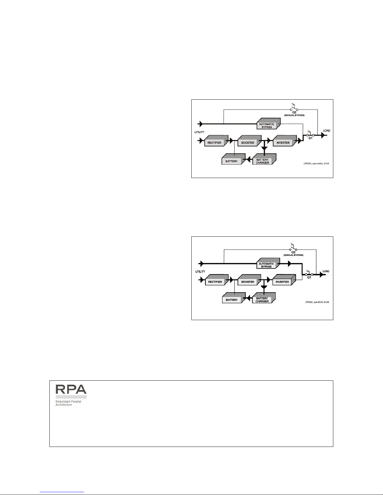
VFI (Voltage Frequency Independent) mode operation
Under normal conditions the load is
permanently powered by the inverter with
constant amplitude and frequency.
The rectifier, powered by the utility, supplies the
inverter and the battery-charger keeps the
battery fully charged.
Fig. 4.2-1 Energy flow in VFI Mode operation
The inverter converts the DC voltage in a new AC sine wave voltage with constant amplitude and
frequency independently from the input utility power.
ECO Mode operation (Intelligent Energy Management)
When the ECO Mode is selected, and the utility
power is available, the load is normally powered
through the automatic bypass.
When the utility voltage is detected out of the
prescribed tolerances, the load is automatically
transferred to the inverter.
When the utility recovers, the load returns to the
automatic bypass after a variable time defined
by the control unit.
Fig. 4.2-2 Energy flow in ECO Mode operation
The ECO Mode can be configured directly by the user for higher efficiency, considering the utility
reliability and criticality of the load.
The selection between the two operation modes “VFI Mode and ECO Mode”, or switching between
operation modes at required time, can be done through the UPS control panel (see Section 5.3).
In case of parallel system
ECO Mode cannot be enabled for RPA Parallel System.
Attention: A single unit equipped with a RPA - Parallel board, must be considered as parallel, thus
disabling ECO Mode.
Page 14
Modifications reserved Page 14/65
OPM_LPS_3UO_50K_60K_1US_V010.doc Operating Manual LP 33U Series 30 & 40 kVA
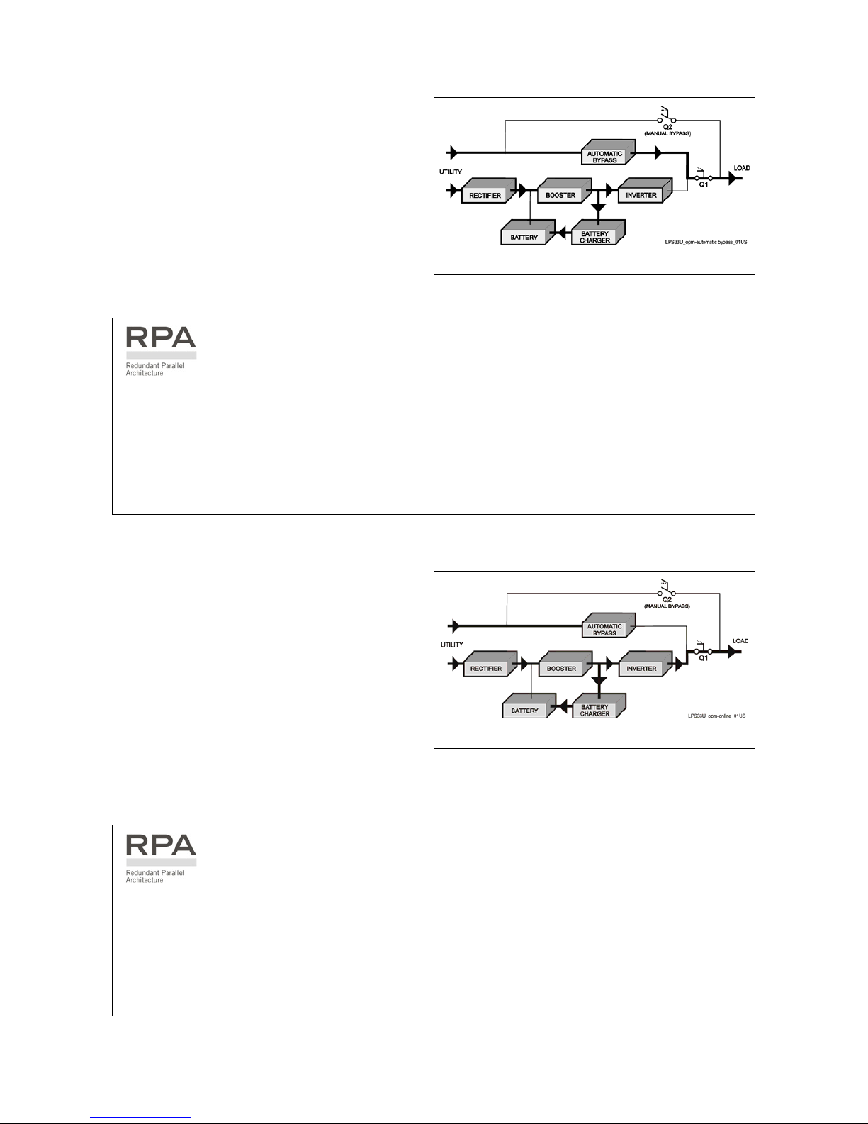
Automatic bypass operation
In VFI (Voltage Frequency Independent) operation
mode, the load is permanently supplied by the
inverter but, in case of trouble on the inverter, or
when overload or short-circuit on the output
occur, if the utility voltage do not exceed the
admitted tolerances, the load is instantly
transferred to the utility through the automatic
bypass, taking advantage of the higher short
circuit power.
Fig. 4.2-3 Energy flow in automatic bypass operation
When the inverter recovers, the load will be re-transferred automatically to the inverter.
In case of parallel system
Each unit has its own bypass.
All the bypasses in the system work together, their control being managed in the same manner by
all units.
The units are continuously exchanging information before taking such decision.
In case the inverter of one unit fails, its bypass remains operating.
It is excluded only if the unit is separated from the common bus by opening its output switch Q1.
Utility recovery operation
As soon as the ‘utility’ recovers, the rectifier
starts up automatically supplying the inverter
and the battery-charger recharges the battery.
In case the inverter has been shut down
following a complete discharge of the battery,
when the utility recovers the system start up
automatically.
Fig. 4.2-4 Energy flow at utility recovery operation
When the energy stored in the battery is sufficient to ensure a minimum time of operation with the
actual load, in case of a future utility failure, the load will be retransferred to inverter (if selected VFI
Mode).
In case of parallel system
When the AC input power recovers, the rectifiers will start up sequentially according to their
number in the parallel system in order to avoid an initial inrush current.
The inverters will start up automatically, but only when the battery has recharged enough for a
minimum runtime with the present load.
When enough inverters to supply the load have been restarted, the load will be transferred from the
automatic bypass back to the inverter bus bars.
Page 15
Modifications reserved Page 15/65
OPM_LPS_3UO_50K_60K_1US_V010.doc Operating Manual LP 33U Series 30 & 40 kVA
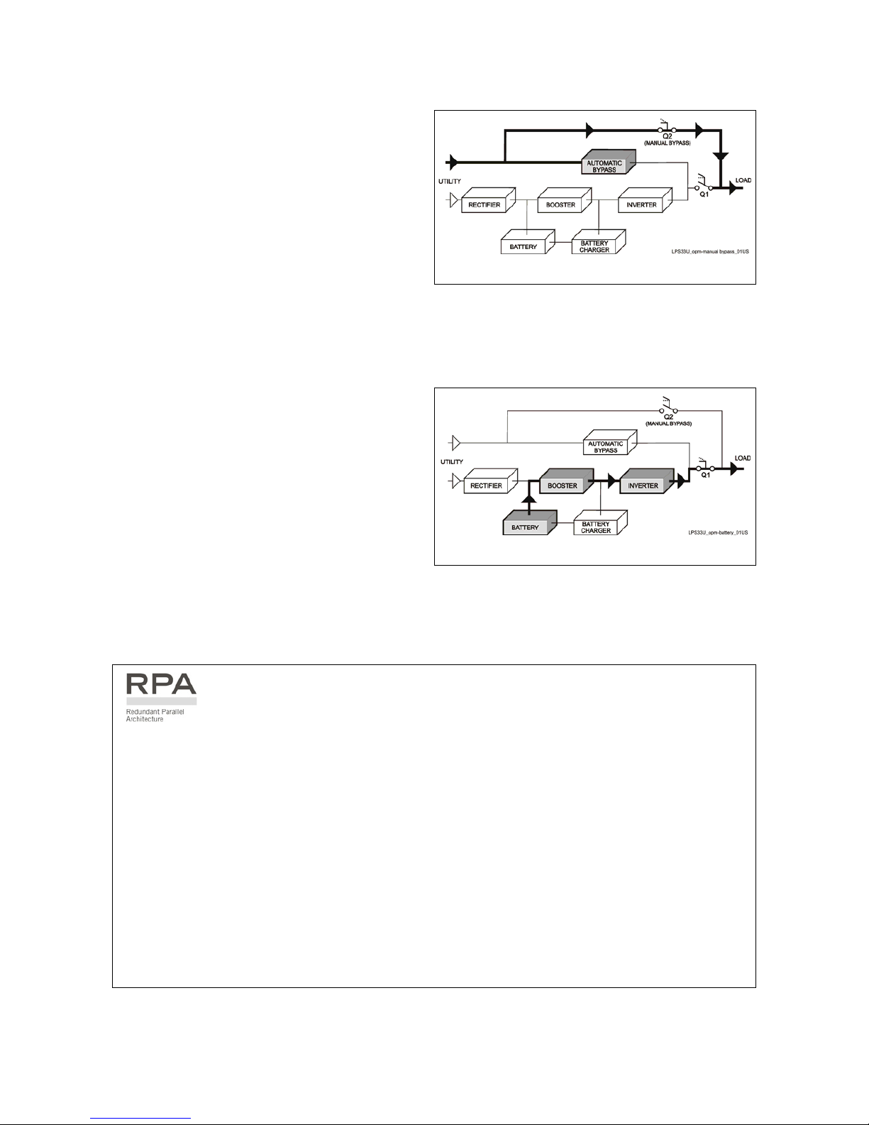
Manual bypass operation
The manual bypass circuit consisting of Q1 and
Q2 manual switches permits the transfer of the
load directly to the utility without interruption,
leaving the UPS galvanically separated from the
output load.
This type of operation is normally used when the
UPS system must be completely turned off for
maintenance or reparation.
Fig. 4.2-5 Energy flow in manual bypass operation
Utility failure operation
In the event of a utility power failure, the
rectifier and the battery-charger turn OFF,
while the inverter continues to supply the load
without interruption using the energy stored in
the battery.
During the battery discharge, the LCD screen
displays the remaining autonomy, based on the
battery capacity and the applied load.
Fig. 4.2-6 Energy flow during utility failure operation
In the event of an extended utility failure, before the battery is fully discharged, the alarm “stop
operation” warns the user that the UPS will start the shutdown procedures when the indicated time
expired (normally 3 minutes).
In case of parallel system
With parallel system for power capacity:
• With the bypass utility power available as the warning “battery low” occurs on one unit, after
timeout (selectable) the load is transferred to utility.
• With missing bypass utility power as the warning occurs on one unit, the system starts the
timeout (selectable) of “Stop operation” and then the output load shuts down.
With redundant parallel system:
• As the warning battery low occurs on one unit unnecessary to support the present load, after
timeout (selectable) this unit shuts down and the load is shared between the other units.
As the warning occurs on one unit necessary to support the present load, the system starts the
timeout (selectable) of “stop operation” and then the output load shuts down.
Page 16
Modifications reserved Page 16/65
OPM_LPS_3UO_50K_60K_1US_V010.doc Operating Manual LP 33U Series 30 & 40 kVA
4.3 RPA PARALLEL SYSTEM
The RPA (Redundant Parallel Architecture) allows to extend the unit to a parallel system with 2, 3, or 4
units LP 33U Series connected on the same bus, which ensure the highest reliability rate and increase
the power availability.
Parallel system for power capacity
Two or more units can be paralleled in order
to achieve output power superior to the
maximum power delivered by a single UPS
unit.
The maximum total load shared between
the n parallel units can achieve the 100% of
the installed nominal power system.
In the event of one unit fails, the load will be
suddenly transferred to the mains by the
bypass.
Parallel system for redundancy
The parallel system can be defined
redundant only in case the nominal power
rating of n-1 units of n parallel units is
sufficient to supply the required load power.
g
Digital Energy
Battery System
g
Digital Energy
UPS System
g
Digital Energy
Battery System
g
Digital Energy
UPS System
g
Digital Energy
Battery System
g
Digital Energy
UPS System
g
Digital Energy
Battery System
g
Digital Energy
UPS System
Fig. 4.3-1 RPA system diagram
The load in a parallel redundant system, is equally shared by n units connected on the output bars.
Should one of the parallel units trip off-line, the remaining (n-1) units will share the load maintaining the
applications protected by inverter until the normal situation restores.
Load sharing between parallel units
The control bus exchanging the data between the microprocessors of the paralleled units provide for a
constant proportional load sharing in every load condition.
Management and synchronization of the parallel system
All the units are identical without master and slaves.
One unit is arbitrarily selected as the reference (the first unit connected on power bus) being this unit the
first synchronized with the mains voltage, and all the other units synchronize with the first one.
In case the reference unit fails or it is excluded from the parallel power bus any other unit will take over
the reference role.
The AC input power source of all the bypasses must be the same for all the units of the parallel system
excluding any phase shift between them.
Control bus of the parallel system
A high-speed serial bus, guarantees communication, synchronization and load sharing between the
UPS modules.
Each module controls it’s own function, while the Master (each unit can be Master) controls and
commands the status of the system.
NOTE !
The parallel system excludes more rectifiers connected on common battery.
No transformers, fuses or automatic circuit breakers should be inserted between
the unit’s output and the load common bus bars.
Page 17
Modifications reserved Page 17/65
OPM_LPS_3UO_50K_60K_1US_V010.doc Operating Manual LP 33U Series 30 & 40 kVA
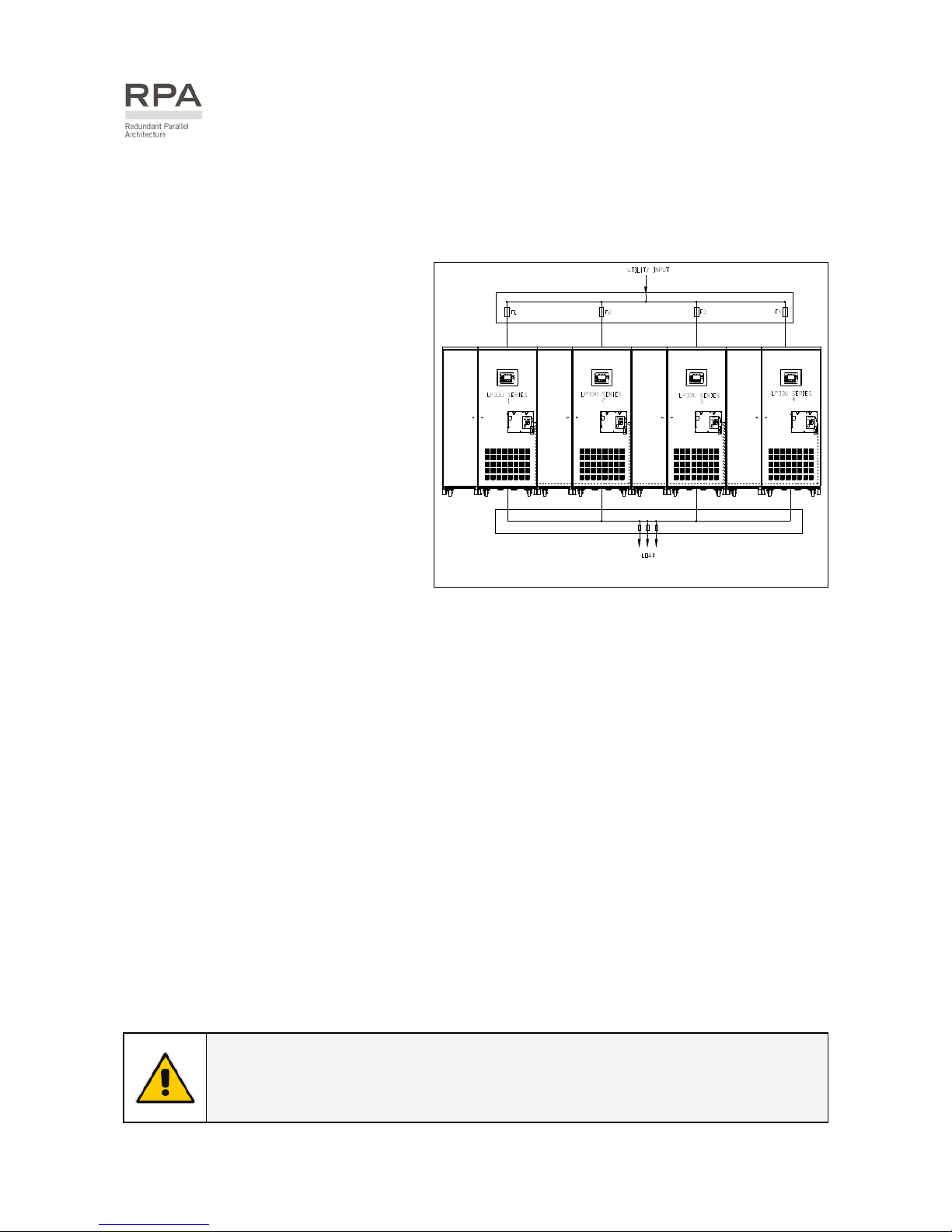
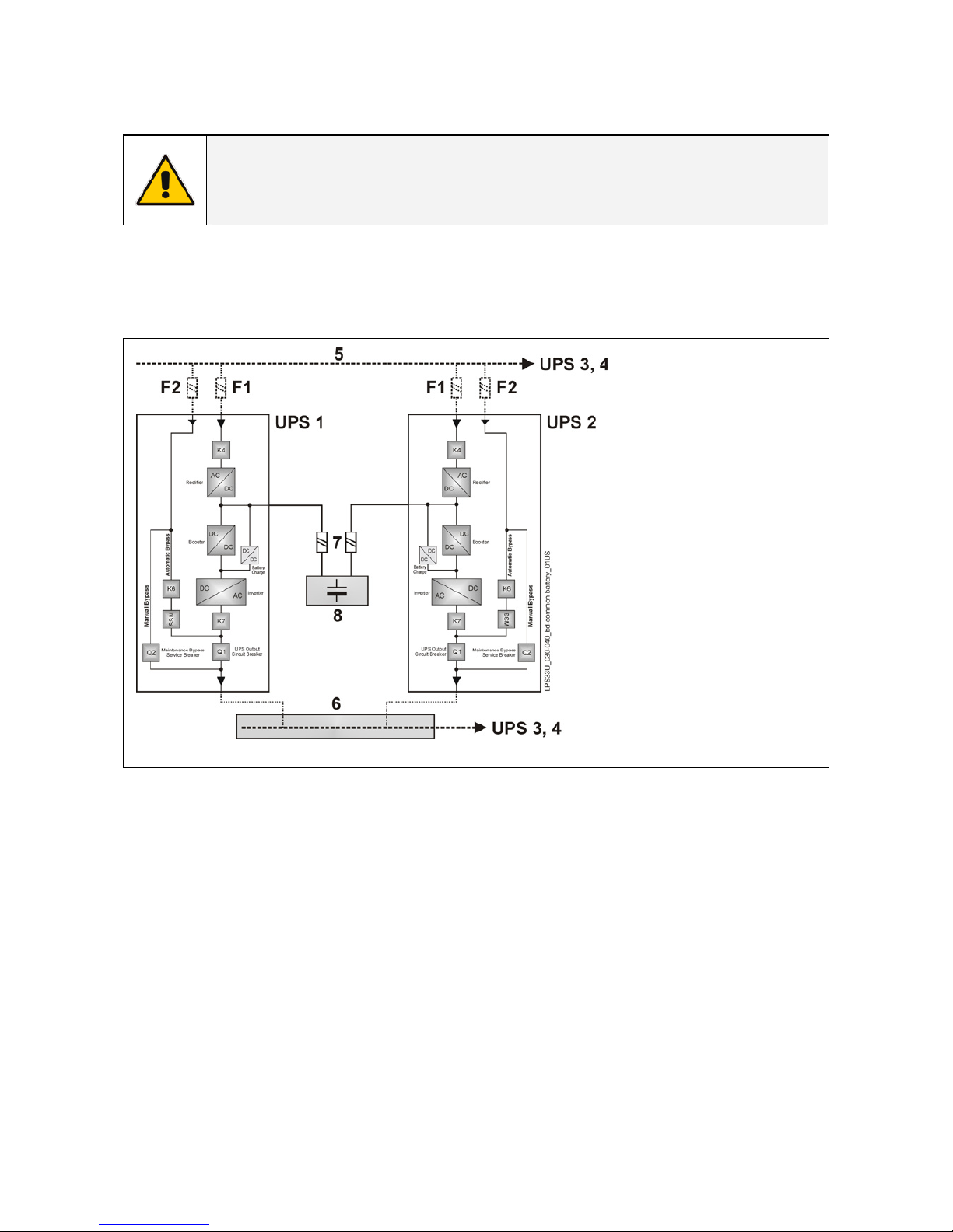
4.4 UPS PARALLELED ON THE SAME BATTERY
NOTE !
A parallel system with a Common Battery for two or more UPS, requires a
particular installation and adequate setting of some parameters, (accessible only
through password), and can therefore only be done by a qualified GE engineer.
Usually each UPS Unit runs with its own Battery.
In case of parallel units running with a Common Battery (max. 4 UPS - see Fig. 3.4-1), the sharing circuit
between the individual UPS is integrated in the communication bus of the system in order to assure an
equal sharing of the Rectifiers output currents.
Fig. 4.4-1 Diagram RPA system with UPS on common battery
1 –
2 –
3 –
4 –
5 –
6 –
7 –
8 –
Rectifier
Inverter
Automatic Bypass
Manual Bypass
Mains Power
Load Bus Bar
External Battery Fuse
Battery
Pay attention to the following recommendations:
• The units delivered for this functioning mode needs a special parameters setting, so they must be
prepared in advance before the installation.
• The installation must be performed only with the UPS system completely shut down.
• The AC Rectifiers input power (5) must be the same, with clockwise phase rotation for each unit.
• Each Rectifier must be set for the same floating DC voltage and the same Battery current limitation.
• It is mandatory to install the fuses / MCB (7) on each line connecting the Rectifiers to the common
Battery for maintenance / safety reasons (see Section 4.7.2).
• In case a unit must be powered down for maintenance, switch-OFF the concerned unit before open
the DC fuses / MCB on the Battery line (7).
• If an emergency generator set supplies the UPS, and the free contact “Generator ON” is connected
to the Customer Interface, connect a separate NO free contact on each parallel unit.
• Do not connect the temperature sensor for automatic battery floating voltage compensation.
• Do not enable the function Boost charge.
Page 18
Modifications reserved Page 18/65
OPM_LPS_3UO_50K_60K_1US_V010.doc Operating Manual LP 33U Series 30 & 40 kVA
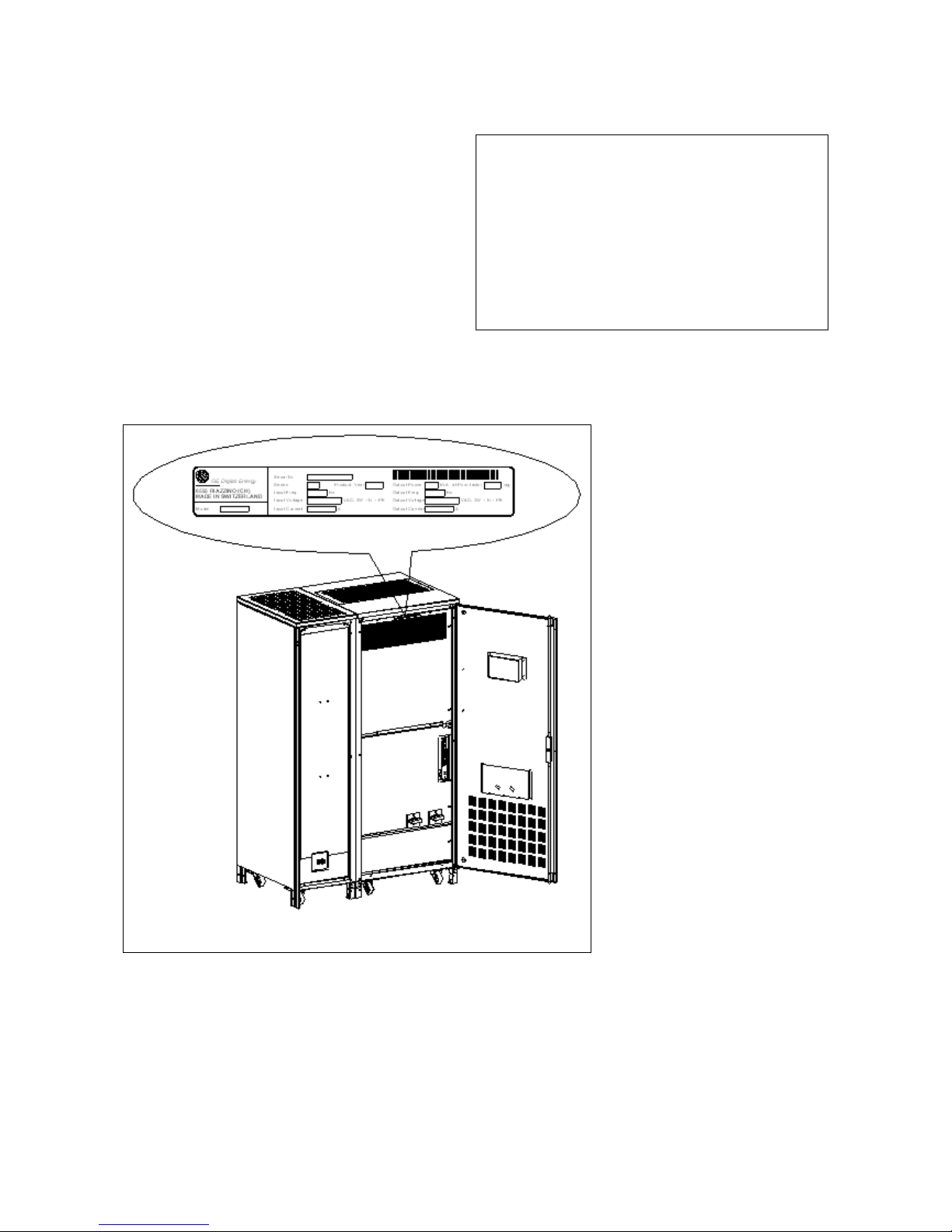
4.5 SERVICE AND TECHNICAL SUPPORT
For any request of technical support please
contact the supplier who provided the system.
Stamp of your Dealer or local responsible of the Technical Assistance
(see page 3)
Fig. 4.5-1 Identification label
The requested data permitting
to identify your UPS are
marked on the identification
label fixed on the front of the
cabinet, behind the lower front
door.
For fast and efficient Technical
Support solutions, please
mention the data marked on
the identification label.
Page 19
Modifications reserved Page 19/65
OPM_LPS_3UO_50K_60K_1US_V010.doc Operating Manual LP 33U Series 30 & 40 kVA
4.6 RECYCLING AT THE END OF SERVICE LIFE
NOTE !
This product has been designed to respect the environment, using
materials and components respecting eco-design rules.
It does not contain CFCs (chlorofluorocarbons) or HCFCs
(hydrochlorofluorocarbons).
GE, in compliance with environment protection recommends to the
User that the UPS equipment, at the end of its service life, must be
recovered conforming to the local applicable regulations.
WARNING !
Leads contained in the batteries is a dangerous substance for the
environment, therefore it must be correctly recycled by specialized
companies!
Page 20
Modifications reserved Page 20/65
OPM_LPS_3UO_50K_60K_1US_V010.doc Operating Manual LP 33U Series 30 & 40 kVA
5 SYSTEM HANDLING
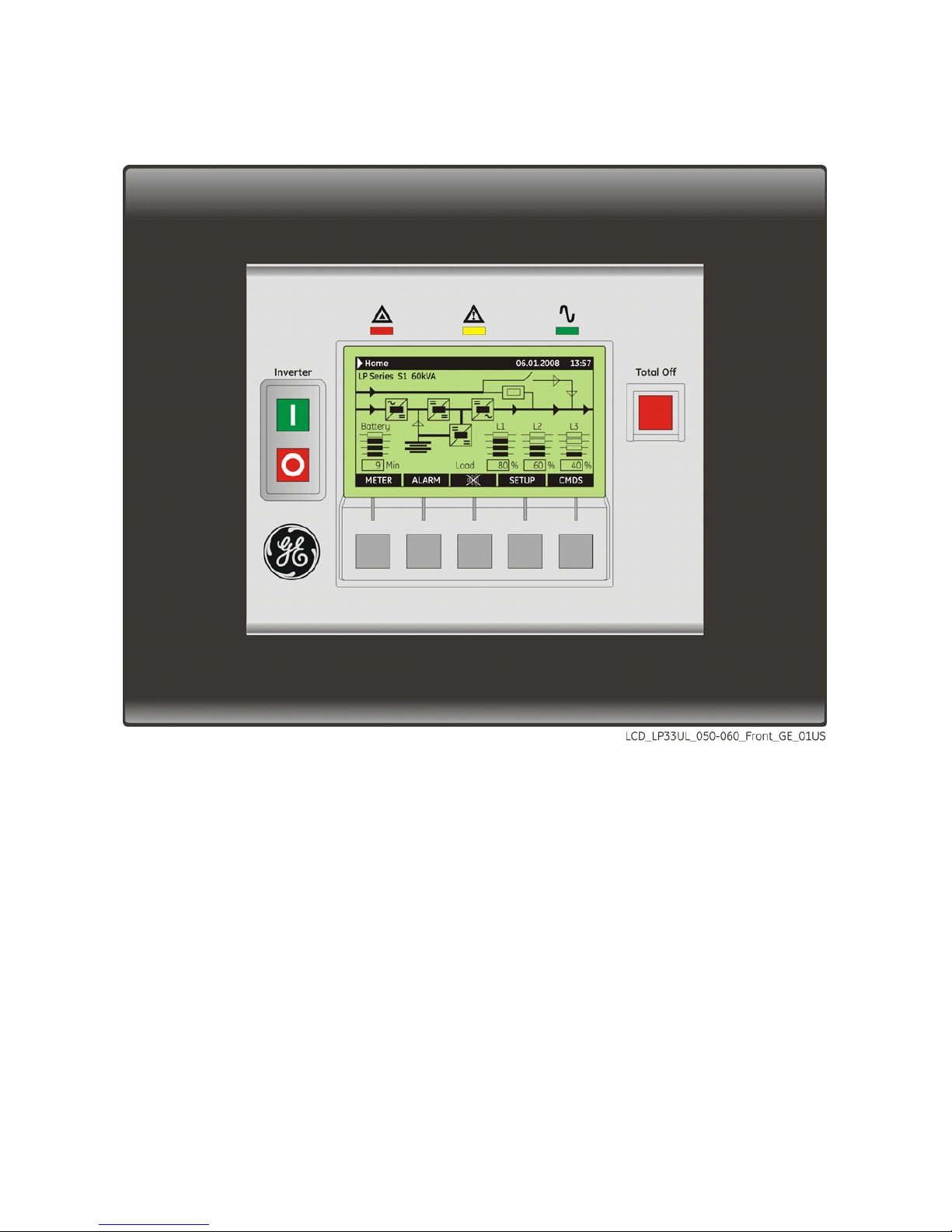
5.1 CONTROL PANEL
Fig. 5.1-1 Control panel
The control panel, positioned on the UPS front-top, acts as the UPS user interface and comprises of the
following elements:
• Back lit Graphic Display (LCD) with the following characteristics:
− Multilanguage communication interface:
English, German, Italian, Spanish, French, Finnish, Polish, Portuguese, Czech, Slovakian, Chinese,
Swedish, Russian and Dutch.
− Synoptic diagram indicating UPS status.
• Command keys and parameters setting.
• UPS status control LED.
Page 21

Modifications reserved Page 21/65
OPM_LPS_3UO_50K_60K_1US_V010.doc Operating Manual LP 33U Series 30 & 40 kVA
5.2 TABLE OF FUNCTIONS AND INDICATIONS ON CONTROL PANEL
Key to switch the Inverter ON ( I )
Key for Inverter shutdown ( O )
Press key to transfers the Load to Utility.
Keep pressed for 5 seconds to shutdown the Inverter.
This key is also used as the EPO (Emergency Power Off) reset.
Key “Total Off”
The key “Total Off” is protected by a transparent cover.
By pressing it, you immediately separate the UPS from the Load.
It is possible to activate the command “Total Off” using the following screen:
COMMANDS / REQUEST TOTAL OFF. See Section 6.5.
Attention: “TOTAL Off” cannot disconnect the UPS from the Load with Q2 closed.
`Home\Commands
COMMANDS
RESET TOTAL OFF
REQUEST TOTAL OFF
To reset “Total Off”
Restore the command “Total Off”
by entering the screen:
COMMANDS / RESET TOTAL OFF
V
For Parallel System: if “Total Off” is pressed on one unit connected to
the parallel bus (switch Q1 closed), all the units are separated from the load.
The “Total Off” reset must be done only on one unit connected to the parallel bus
(switch Q1 closed).
NOTE !
Special care must be taken in using this command, in order to
avoid accidental load disconnection.
Page 22

Modifications reserved Page 22/65
OPM_LPS_3UO_50K_60K_1US_V010.doc Operating Manual LP 33U Series 30 & 40 kVA
LED Stop Operation (red color)
It warns about the imminent inverter stop (default parameter = 3 min.) and the
consequent load shutdown as result of:
• The battery is fully discharged and the load cannot be transferred on utility.
• Over temperature or overload condition (>125%) and the load cannot be
transferred on utility.
LED Alarm (yellow color)
It blinks when one or more alarm is activated. The internal buzzer is ON.
The LED Alarm remains lit (with the alarm condition still present) and the buzzer
stops when the key “MUTE” is pressed.
LED Alarm is lit when the load is not protected by UPS or in case Q1 is open.
LED Operation (green color)
When lit, indicates that the UPS is functioning correctly and the load is system
protected (Load supplied either from inverter or from Automatic Bypass in case of
ECO Mode functionality).
When blinking, indicates that a regular maintenance service is needed (SERVICE
REQUIRED).
May be reset by a service technician only.
See Section 9 – Maintenance – Service check.
The LED is OFF when the output switch Q1 is open, indicating that the Inverter is in
service mode, not supplying the load.
User LCD Interface
The user interface consists of a Back lit Graphi
c
Display (LCD) having:
• Synoptic diagram indicating UPS status.
• UPS operating, AC and DC metering
information.
• History of events (alarms and messages).
• Functionality can be programmed to meet
customer needs by changing parameters.
• Operation commands of the UPS.
Page 23

Modifications reserved Page 23/65
OPM_LPS_3UO_50K_60K_1US_V010.doc Operating Manual LP 33U Series 30 & 40 kVA
5.3 SWITCHES
Q1 - UPS output switch
Q2 - Manual bypass switch
NOTE !
Do not switch ON Q1 and Q2, while
Inverter is ON.
Fig. 5.3-1 Q1 and Q2 switches
NOTE !
Mains failure of long duration or low Battery voltage will cause the automatic
shutdown of the UPS, thus preventing damage to the Battery.
Page 24

Modifications reserved Page 24/65
OPM_LPS_3UO_50K_60K_1US_V010.doc Operating Manual LP 33U Series 30 & 40 kVA
6 LCD SCREEN
6.1 HOME SCREEN
Fig. 6.1-1 LCD display
The keys perform the following functions:
METER
METERING View electric parameters values and statistics of use.
See Section 6.2.
ALARM
ALARMS Shows in chronological order, all the events occurred (alarms,
messages, commands, handling, etc.). See Section 6.3.
MUTE Key to reset general alarm and buzzer.
SETUP
SETUP Allows the user to customize some UPS functions to specific
requirements and to view UPS identification data. See Section 6.4.
CMDS
COMMANDS Allows the user to execute UPS operation commands.
See Section 6.5.
The LCD screen, after 5 minutes of inactivity, shuts down the backlight.
To reactivate it, it is sufficient to press any keys.
If the keypad remains inactive for 5 minutes or longer, during the viewing of a screen such as
MEASURES, ALARMS, SETUP or COMMANDS, the LCD screen returns automatically to the main screen.
It is possible to view any key functional description by pushing the key for more than 3 seconds.
Pushing the key “MEASURES” and “ALARMS” together automatically sets the LCD communication for
“ENGLISH”.
Page 25

Modifications reserved Page 25/65
OPM_LPS_3UO_50K_60K_1US_V010.doc Operating Manual LP 33U Series 30 & 40 kVA
LP Series S1 60kVA
UPS Model UPS series number UPS nominal rating (kVA)
Battery level LED
All LED light indicate a battery autonomy of 100%.
LED A Fixed: indicates battery autonomy between 6% and 25%.
Blinking: indicates battery autonomy ≤5%.
LED A, B Indicate battery autonomy between 26% and 50%.
LED A, B, C Indicate battery autonomy between 51% and 99%.
Min: Battery autonomy time in minutes estimates with actual load.
Load level LED
All LED Off indicate a load status at ≤25%.
LED A Indicates a load level between 26% and 50%.
LED A, B Indicate a load level between 51% and 75%.
LED A, B, C Indicate a load level between 76% and 100%.
LED A, B, C, D Indicate a load level between 101% and 124%.
LED D blinking Indicates a load level ≥125%.
Fig. 6.1-2 LEDs on synoptic diagram
LEDs on synoptic diagram
LED 1 Utility rectifier OK
LED 2 Utility bypass OK
LED 3 Rectifier ON
LED 4 Discharging battery
LED 5 Booster ON
LED 6 Charge battery ON
LED 7 Inverter available
LED 8 Inverter ON
LED 9 Q1 closed
LED 10 Automatic bypass ON
LED 11 Manual bypass Q2 ON
LED 12 Load on UPS
Examples of typical scenarios in the synoptic diagram:
Load supplied by inverter Load supplied by automatic bypass
Load supplied by manual bypass Q2 Load supplied by battery
Page 26

Modifications reserved Page 26/65
OPM_LPS_3UO_50K_60K_1US_V010.doc Operating Manual LP 33U Series 30 & 40 kVA
6.2 METERING
The METERING mode is entered any time the “METER” key is pressed.
The LCD screen will indicate a series of screenshots showing the measures of all electric parameters like
AC, DC and various statistics.
In this mode the keys perform the following functions:
Return to HOME screen.
Scrolls backward to the previous screen.
Scrolls forward to the next screen.
It is possible to view any key functional description by pushing the key for more than 3 seconds.
`Home\Meter
BATTERY
Vp 164 V
Vn 164 V
T +25° C
Charge level 80 %
Autonomy 8 Min
Charger mode Off
Battery data screen
Vp Voltage of positive (+) battery string.
Vn Voltage of negative (-) battery string.
T The temperature of the battery (“SENSOR DISABLE”
indicates sensor disabled).
Charge level The battery charge level.
Autonomy The estimated backup time with the
present load.
Charger mode The functionality of SBM (Superior Battery Management) can help to reduce the battery
recharging time, and improve the lifetime of the battery.
Beside the indication of the battery voltage on the display, a letter shows, according to the
table below, the operational status of SBM:
Abbreviation Status of charger Charger voltage Description
Off
OFF 0 Vdc Battery open circuit voltage
Top
ON Boost (176 Vdc) Boost charge with new Battery
Float
ON Floating (164 Vdc) Battery charged
Low
ON Floating (164 Vdc) Normal charge
Boost
ON Boost (176 Vdc) Boost charge
Equalize
ON Boost (179 Vdc) Battery equalization
Access to the Parameters for setting the SBM mode is password protected.
Please call your Service Center.
`Home\Meter
BOOSTER
f : 60.0 Hz
L1 : 120 V
L2 : 120 V
L3 : 120 V
Vp : 215 V
Vn : 215 V
Booster data screen
f The input frequency of the rectifier.
L1
L2 Input line voltage L1, L2 and L3 phases.
L3
Vp Voltage of positive (+) booster string.
Vn Voltage of negative (-) booster string.
Page 27

Modifications reserved Page 27/65
OPM_LPS_3UO_50K_60K_1US_V010.doc Operating Manual LP 33U Series 30 & 40 kVA
`Home\Meter
UTILITY
f 60 Hz
L1 120 V
L2 120 V
L3 120 V
BYPASS FREE
Bypass utility data screen
f The frequency of the utility.
L1
L2 3-phase utility voltage PHASE /NEUTRAL.
L3
Bypass Bypass status: FREE / LOCKED.
`Home\Meter
INVERTER
f 60 Hz
L1 120 V
L2 120 V
L3 120 V
T OK
SYNCHRONIZED
Inverter data screen
f The output frequency of the Inverter.
L1
L2 3-phase output voltage PHASE/NEUTRAL.
L3
T The temperature of the inverter bridge (OK / MAX).
The synchronization status of the inverter with respect to
utility (Synchronized / Not Synchronized).
`Home\Meter
MODULE LOAD
L1 : 120 V 56.0 A 50 %
L2 : 120 V 56.0 A 50 %
L3 : 120 V 56.0 A 50 %
LOAD ON INVERTER
Module load screen
… V Output voltage PHASE/NEUTRAL for each phase.
… A The output current as RMS values (RPA: value for
each UPS).
… % The output load as percentage (RPA: value for each
UPS).
The source of the power supplied to the load.
`Home\Meter
COUNTERS
Bypass utility failure : 53
Rectifier utility failure : 35
Overloads : 15
InvOperTime [h] : 2135
UPSOperTime [h] : 3125
Statistics screen
The total number of minor utility faults (bypass utility out of
tolerance faults).
The total number of times a gap of utility in the rectifier has
been reordered.
The total number of detected output overloads.
The total operating time for the Inverter (in hours).
The total operating time for the UPS (in hours).
`Home\Meter
UTILITY
NUMBER OF FAST TRANSIENTS
<2ms >2ms >5ms >10ms
25 20 7 5
ECO MODE RATE = 70 %
ECO Mode statistic screen
This screen is enabled only for a single UPS, not for an RPA
Parallel System.
The number of fast transients occurred on the bypass
utility on the last seven days.
The statistic evaluation in % (100= good; 0= bad) of the
utility, for the ECO mode operation.
Page 28

Modifications reserved Page 28/65
OPM_LPS_3UO_50K_60K_1US_V010.doc Operating Manual LP 33U Series 30 & 40 kVA
6.3 ALARMS
The ALARMS mode is entered any time the “ALARM” key is pressed.
The LCD will display a series of screens corresponding to the last 255 events, two events per screen
(LEVEL 1 USER).
In this mode the keys perform the following functions:
Return to HOME screen.
Scrolls backward to the previous screen.
Scrolls forward to the next screen.
U
Move forward to the following event.
V
Move back to the following previous event.
Confirm the selection made.
It is possible to view any key functional description by pushing the key for more than 3 seconds.
The events displayed are the standard GE events as described in the Section 6.3.1 - EVENTS (Alarms
and Messages).
`Home\ Alarm
ALARM
LEVEL 1
:
USER
LEVEL 2
:
SERVICE
V
Alarms screen
LEVEL 1 USER
Chronologically view 2 events per screenshot.
LEVEL 2 SERVICE
Chronologically view 5 events per screenshot with service
related info.
`Home\Alarm\User
NR = 255 06.05.2008 15.37.25
C = 4404 K6 CLOSING FAILURE
S = 00008180
NR = 254 06.01.2008 12.45.57
C = 4583 COMMAND TO SYNCHRONIZE
S = 00008180
U
V
Screen of user alarms
NR Number chronologically assigned to an event (Nr.
255 is the more recent, Nr. 1 is the first).
Date and exact hour of the moment when the event
occurred.
C Number of standard GE code of the event and an
explicit text describing the event in the selected
languages.
S Status code of the UPS.
Page 29

Modifications reserved Page 29/65
OPM_LPS_3UO_50K_60K_1US_V010.doc Operating Manual LP 33U Series 30 & 40 kVA
6.3.1 Events (alarms and messages)
Each of the following listed events, alarm or message, can be displayed on the LCD screen, on a PC with
the software “GE Data Protection” installed or with the monitoring system “GE Power Diagnostic”.
Alarms and Messages are differently specified because the alarms are indicating an abnormal
functioning of the UPS (which are additionally signaled with the LED Alarm and acoustically with the
buzzer), while the messages indicate the various states of operation of the UPS (stored in the events list,
but not activating the LED Alarm and the acoustical alarm).
6.3.2 Alarms list
Code Alarm Meaning
4000
SETUP VALUES LOST
Parameters are lost and have been replaced with default
values.
4001
REGULATION BOARD FAILURE
Voltage supply +/-15 Vdc has been detected out of
tolerance on the P2 - Mainboard or the programmable
circuits are defective.
4100
RECTIFIER FUSES FAILURE
The trip indicator mounted on rectifier input fuses indicates
a blown fuse.
The rectifier is turned Off (K4 open) and the load will be
supplied by the battery.
4102
K4 CLOSING FAILURE
K4 not closed despite a closing command being done.
The rectifier is switched OFF.
4103
K4 OPENING FAILURE
K4 not open despite an opening command being done.
The rectifier is switched OFF.
4110
RECTIFIER UTILITY OUT
OF TOLERANCE
Rectifier input utility has been detected out of tolerance
(voltage, frequency or phase).
4115
LOW BATTERY VOLTAGE
The battery has been discharged and reached “stop
operation” time-out (default 3 minutes), the inverter will be
shut down.
It restarts automatically only when the battery has
recovered energy to ensure min. a “stop operation” time to
the actual load.
4116
HIGH BATTERY VOLTAGE
Dangerous high DC-Voltage.
Causes Inverter shutdown.
Inverter restarts automatically after return to normal
floating voltage.
4118
BATTERY FAULT
During battery test the DC voltage falls under the critical
level.
If the boost voltage has not been reached within 24 hours,
then the charge voltage returns to floating voltage.
Battery test is stopped.
4130
TURN ON RECT.
OR SHUTDOWN UPS
Rectifier and inverter are OFF.
The DC power supply is discharging the battery slowly.
Rectifier must be restarted or battery must be disconnected
in order to avoid damages.
4140
RECTIFIER CONTROL FAILURE
Rectifier voltage hasn’t reached the set value.
Probably fault on regulation loop.
The DC capacitors are not equally charged (more of 50 Vdc
of difference).
The rectifier is switched OFF.
Page 30

Modifications reserved Page 30/65
OPM_LPS_3UO_50K_60K_1US_V010.doc Operating Manual LP 33U Series 30 & 40 kVA
Code Alarm Meaning
4301
INVERTER FUSES FAILURE
Inverter output fuses blown.
Signaled by electronic detector.
Inverter can be started manually after replacement of
fuses.
4304
K7 CLOSING FAILURE
K7 not closed despite a closing command being done.
Signaled by auxiliary contact.
The load will be supplied by utility.
4305
K7 OPENING FAILURE
K7 not open despite an opening command being done.
Signaled by auxiliary contact.
The load will be supplied by utility.
4312
INV. VOLTAGE OUT
OF TOLERANCE
Inverter output voltage is out of the tolerances defined in
respective parameter (±10%).
Inverter is switched OFF.
4320
ISMAX DETECTION
Detection of inverter bridge (Is) current limitation cause
inverter OFF and possible automatic restart.
After 3 times inverter switches OFF for persistent Is max
detection in time.
Inverter switch OFF, and it can be restarted manually.
4340
INVERTER CONTROL FAILURE
The slave oscillator is not synchronized with the master,
thus causing the shutdown of it’s inverter.
4347
OSCILLATOR FAILURE
Auto calibration of the Inverters free run frequency was not
possible.
The oscillator frequency of this unit is out of tolerance.
4402
RECTIFIER CANNOT BE
TURNED ON
The rectifier cannot be turned on because the DC link
voltage has not reached the requested value.
4404
K6 CLOSING FAILURE
K6 not closed despite a closing command being done.
Signaled by auxiliary contact.
The load cannot be supplied by electronic bypass.
4405
K6 OPENING FAILURE
K6 not open despite an opening command being done.
Signaled by auxiliary contact.
4410
BYPASS UTILITY OUT
OF TOLERANCE
The utility bypass voltage is out of the tolerances (±10%).
K6 opens, synchronization with utility is inhibited and
transfer to utility is blocked.
4520
NO INVERTER POWER
The load supplied by utility is over 100%.
The load remains blocked on utility as long as alarm
overload is active.
4530
LOAD LOCKED ON UTILITY
Load is locked on utility because 3 transfers on utility have
been detected in a short time (default 30 seconds).
Transfer will be free again after a time defined by
respective parameter (default 30 seconds).
4531
LOAD ON UTILITY
BY ERROR DETECTOR
Load is transferred to utility because the error detector
detected a disturbance on the output voltage.
4563
EMERGENCY OFF ACTIVATED
Alarm after detection of an Emergency Off from an
external safety device connected on Customer Interface.
Consequently K4, K6 and K7 open and shut down inverter,
booster and rectifier.
4570
OVERLOAD
The UPS-System is in an overload condition >125% on
inverter, or >150% on utility.
A sequence of “stop operation” starts.
Time out depending on load quantity.
Page 31

Modifications reserved Page 31/65
OPM_LPS_3UO_50K_60K_1US_V010.doc Operating Manual LP 33U Series 30 & 40 kVA
Code Alarm Meaning
4571
OVERLOAD: LOAD ON UTILITY
With utility bypass supply available and load >115%, the
load is transferred on utility.
Load will be transferred again automatically on inverter
when load will be <100%.
4581
INVERTER AND UTILITY
NOT SYNCHRONIZED
The voltages of utility and inverter are not synchronized,
which causes the opening of K6.
4697
BATTERY OVERTEMPERATURE
The battery temperature exceeds the value inserted in
parameter.
Disabled with parameter (service only).
4698
BATTERY POWER INSUFFICIENT
In case of utility failure, with the actual load, the autonomy
time would result below “stop operation” time (default 3
minutes).
4700
DC LOW
Battery voltage is at the lowest limit.
Shutdown of inverter until the battery voltage reaches the
value in respective parameter.
4900
LOAD LOCKED ON INVERTER
The load is locked on Inverter following 3 load transfers
within 30 seconds.
After time out of the value in respective parameter (default
30 seconds), bypass will be free.
4955
OVERTEMPERATURE
An over temperature condition has been detected on
inverter.
Elapsed “stop operation” time, inverter shutdown.
With utility available, load is transferred on utility.
4998
LOAD OFF DUE TO
EXTENDED OVERLOAD
Load Off after time-out of “stop operation” for overload on
inverter or bypass (time depending on the % of overload).
4999
LOAD OFF DUE
TO LOW BATT. OR TEMP.
Load Off after time-out of “stop operation” with missing
utility due to battery low voltage or over temperature
condition.
Page 32

Modifications reserved Page 32/65
OPM_LPS_3UO_50K_60K_1US_V010.doc Operating Manual LP 33U Series 30 & 40 kVA
6.3.3 Messages list
Code Message Meaning
4111
RECTIFIER UTILITY OK
Rectifier input utility is again within the acceptable
tolerance (voltage, frequency and phase).
4114
UPS SHUTDOWN
(LOW BATTERY VOLTAGE)
The UPS is in Load OFF status, resulting in Battery supply
for the power supply.
Should the Battery voltage decrease to a value below of
the one set in a parameter, then power supply will
shutdown to avoid damage to the Battery
4119
BATTERY TEST STARTED
Start of manual or automatic battery test.
Rectifier output voltage is decreased to the value defined
by respective parameter.
4120
BATTERY TEST STOPPED
End battery test.
End of manual or automatic battery test.
Rectifier output voltage is restored to floating voltage.
4141
ISMAX DETECTION RECTIFIER Detection of persistent booster (Is) current limitation.
4161
RECTIFIER ON Rectifier received the command to switch ON.
4162
RECTIFIER OFF
Rectifier received the command to switch OFF for:
input utility out of tolerance / EPO / DC-Voltage max.
4163
GENERATOR ON
Customer Interface (X1 / 11, 22) received a Gen set ON
signaling. Operating mode dependent on setting of
respective parameters.
4164
GENERATOR OFF
Customer Interface (X1 / 11, 22) received a Gen set OFF
signaling. Function bypass enabled dependent on setting
of respective parameter.
4302
INVERTER CANNOT BE
TURNED ON
Inverter cannot be switched on because one of the
following conditions are still present:
- Over temperature
- Low battery voltage
- Inverter fuses
- Overload
- K7 opening failure
- High battery voltage
- DC low
- EPO (Emergency Power Off)
4303
INVERTER CANNOT BE
TURNED OFF
Inverter cannot be switched OFF, because the load cannot
be transferred on utility (voltage out of tolerance, not
synchronizing, bypass blocked).
4361
INVERTER ON
The command to start the inverter has been activated on
the control panel.
4362
INVERTER OFF
The command to switch OFF the inverter has been done by
the control panel or automatically for alarm detection.
4411
BYPASS UTILITY OK
Bypass input utility is again within the admitted tolerance
(Voltage, frequency and phase).
4500
COMMAND TOTAL OFF
Disconnection of the load by opening K4, K6 and K7 for:
EPO / Total Off / Overload / Stop operation.
4521
NO BYPASS POWER
With the load supplied by electronic bypass, a utility failure
or K6 opening occurred.
4534
MULTIPLE LOAD TRANSFER
2 transfers inverter-utility have been detected in a short
time, defined by respective parameter (default 30 seconds).
Page 33

Modifications reserved Page 33/65
OPM_LPS_3UO_50K_60K_1US_V010.doc Operating Manual LP 33U Series 30 & 40 kVA
Code Message Meaning
4535
BYPASS LOCKED
Transfer on utility not enabled due to settings of respective
parameters. Contactor K6 is open.
4536
BYPASS FREE
Settings of respective parameters enable bypass transfer
on utility. Contactor K6 can be closed.
4561
TOTAL OFF
Key Total Off behind the front door has been pressed, with
the output circuit breaker Q1 closed.
4562
DETOUR ON
The auxiliary contact indicates that manual bypass Q2 has
been closed.
4564
DETOUR OFF
The auxiliary contact indicates that manual bypass Q2 has
been opened.
4567
COMMAND LOAD ON UTILITY
The control unit received a command to transfer the load
on utility.
4568
COMMAND LOAD ON INVERTER
The control unit received a command to transfer the load
on inverter.
4572
NO MORE OVERLOAD
End of the overload condition previously detected with
alarm 4570.
4580
INVERTER AND UTILITY
SYNCHRONIZED
The voltages of inverter and utility bypass are
synchronized.
4582
COMMAND NOT
TO SYNCHRONIZE
Command not to synchronize with utility has been done for:
utility bypass out of tolerance (alarm 4410) or setting
respective parameters.
4583
COMMAND TO SYNCHRONIZE
Command to synchronize with utility has been done for:
utility BP OK (4410) or setting respective parameters.
4600
COMMAND UPS ON
The ECO Mode function has been disabled or the
programmed time is expired.
The UPS returns to VFI mode supplying the load normally
by inverter.
4601
COMMAND UPS STANDBY
The function ECO Mode is enabled, and according to the
time program the UPS will run in ECO Mode, supplying the
load normally by utility.
4602
Q1 OPEN
The auxiliary contact indicates that the output switch Q1
has been opened.
4603
Q1 CLOSED
The auxiliary contact indicates that the output switch Q1
has been closed.
4699
BATTERY TEST IMPOSSIBLE
Not possible to start battery test (it is postponed) for:
- No utility rectifier or bypass
- Battery not fully charged
- Load is below 10% or above 80%
4763
REMOTE CONTROL ON
Inverter can be started or shutdown by remote control.
Commands source can be chosen depending on the value
of respective parameter (password required):
0 = Only local panel
1 = Only Remote Control
2 = Both
4764
REMOTE CONTROL OFF
Inverter can be started or shutdown by remote control.
Commands source can be chosen depending on the value
of respective parameter (password required):
0 = Only local panel
1 = Only Remote Control
2 = Both
Page 34

Modifications reserved Page 34/65
OPM_LPS_3UO_50K_60K_1US_V010.doc Operating Manual LP 33U Series 30 & 40 kVA
6.3.4 Event report LP 33U Series
In case of failure or malfunction, before calling the nearest Service Center please note the most
important identification data of your UPS and the most recent events displayed.
In order to make the diagnosis easier for our Diagnostic Center we suggest you make a copy of this
page, fill it in with the requested data, and send it by fax.
Unit No: __ __ __ __ __ - __ __ __ __ - __ __ __ __ Series No: ……..….. UPS rating: ……….….. kVA
Customer: ...................................…………….....……. Place: ......................…......................…………………………...…........
Date: ...……..... / ..…......... / ....……….……..... Sent by: ..…...........……..............…………………………............….......…
1. Record the exact UPS status on the panel
when the failure appeared.
2. On the LCD panel, enter the Alarms Mode and
record the alarms/messages in the list below
indicating at least 5 events before the failure
time.
Remark: exact data and time are very important
Event
No.
Event
Code
UPS
Status
Date
Time
h. m. s
255
LED 1
ON OFF
254
LED 2
ON OFF
253
LED 3
ON OFF
252
LED 4
ON OFF
251
LED 5
ON OFF
250
LED 6
ON OFF
249
LED 7
ON OFF
248
LED 8
ON OFF
247
LED 9
ON OFF
246
LED 10
ON OFF
245
LED 11
ON OFF
244
LED 12
ON OFF
243
LOAD
. . . . . . . . . . . . . . . . . . . . .
%
242
BATTERY
. . . . . . . . . . . . . . . . . . . . .
minutes
241
240
Description of repair actions taken:
239
238
237
236
. . . . . . . . . . . . . . . . . . . . . . . . . . . . . . . . . . . . . . . . . . . . . . . . . . . . . . . . . . . . . . . . . . . . . . . . . . . . . . . . . . . . . . . . . . . . . . . . . . . .
. . . . . . . . . . . . . . . . . . . . . . . . . . . . . . . . . . . . . . . . . . . . . . . . . . . . . . . . . . . . . . . . . . . . . . . . . . . . . . . . . . . . . . . . . . . . . . . . . . . .
. . . . . . . . . . . . . . . . . . . . . . . . . . . . . . . . . . . . . . . . . . . . . . . . . . . . . . . . . . . . . . . . . . . . . . . . . . . . . . . . . . . . . . . . . . . . . . . . . . . .
235
Actual situation:
234
233
232
231
. . . . . . . . . . . . . . . . . . . . . . . . . . . . . . . . . . . . . . . . . . . . . . . . . . . . . . . . . . . . . . . . . . . . . . . . . . . . . . . . . . . . . . . . . . . . . . . . . . . .
. . . . . . . . . . . . . . . . . . . . . . . . . . . . . . . . . . . . . . . . . . . . . . . . . . . . . . . . . . . . . . . . . . . . . . . . . . . . . . . . . . . . . . . . . . . . . . . . . . . .
. . . . . . . . . . . . . . . . . . . . . . . . . . . . . . . . . . . . . . . . . . . . . . . . . . . . . . . . . . . . . . . . . . . . . . . . . . . . . . . . . . . . . . . . . . . . . . . . . . . .
230
Remarks:
. . . . . . . . . . . . . . . . . . . . . . . . . . . . . . . . . . . . . . . . . . . . . . . . . . . . . . . . . . . . . . . . . . . . . . . . . . . . . . . . . . . . . . . . . . . . . . . . . . . . . . . . . . . . . . . . . . . . . . . . . . . . . . . . . . . . . . . . . . . . . . . . . . . . . . . . . . . . . . . . . . . . . . . . . . . . . . . . . . . . . . . . . . . . . . . . . . . . . . . . . . . . . . . . . . . . . . . . . . . . . . . .
. . . . . . . . . . . . . . . . . . . . . . . . . . . . . . . . . . . . . . . . . . . . . . . . . . . . . . . . . . . . . . . . . . . . . . . . . . . . . . . . . . . . . . . . . . . . . . . . . . . . . . . . . . . . . . . . . . . . . . . . . . . . . . . . . . . . . . . . . . . . . . . . . . . . . . . . . . . . . . . . . . . . . . . . . . . . . . . . . . . . . . . . . . . . . . . . . . . . . . . . . . . . . . . . . . . . . . . . . . . . . . . .
. . . . . . . . . . . . . . . . . . . . . . . . . . . . . . . . . . . . . . . . . . . . . . . . . . . . . . . . . . . . . . . . . . . . . . . . . . . . . . . . . . . . . . . . . . . . . . . . . . . . . . . . . . . . . . . . . . . . . . . . . . . . . . . . . . . . . . . . . . . . . . . . . . . . . . . . . . . . . . . . . . . . . . . . . . . . . . . . . . . . . . . . . . . . . . . . . . . . . . . . . . . . . . . . . . . . . . . . . . . . . . . .
. . . . . . . . . . . . . . . . . . . . . . . . . . . . . . . . . . . . . . . . . . . . . . . . . . . . . . . . . . . . . . . . . . . . . . . . . . . . . . . . . . . . . . . . . . . . . . . . . . . . . . . . . . . . . . . . . . . . . . . . . . . . . . . . . . . . . . . . . . . . . . . . . . . . . . . . . . . . . . . . . . . . . . . . . . . . . . . . . . . . . . . . . . . . . . . . . . . . . . . . . . . . . . . . . . . . . . . . . . . . . . . .
Page 35

Modifications reserved Page 35/65
OPM_LPS_3UO_50K_60K_1US_V010.doc Operating Manual LP 33U Series 30 & 40 kVA
6.4 SETUP
The SETUP mode is entered any time the “SETUP” key is pressed.
This screen allows the user to modify some parameters permitting to adapt some functions of the UPS
to his/her needs, described as follows.
The LCD will display a series of screens containing the user parameters, accessible without password
protection.
In this mode the keys perform the following functions:
Return to HOME screen.
Scrolls backward to the previous screen.
Scrolls forward to the next screen.
Confirm selected choice of USER / SERVICE level.
Description of the keys to set or modify the parameters:
ESC
Allows to exit a selected screen without making any modification.
U
Scrolls backward to the previous line.
V
Scrolls forward to the next line.
Allows to access a value to be set or modified.
Select, on the same line, the following value or letter to set or modify.
Set or modify the selected value.
Save the set or modified value and return to the selected screen.
It is possible to view any key functional description by pushing the key for more than 3 seconds.
`Home\Setup
UPS IDENTIFICATION
ID : UPS 0
Model : LP Series S1 60kVA
S/N : Q1060-2308-0001
UPS SW Version : xxx
Display SW Version : xxx
UPS identification screen
ID Number of UPS in the RPA Parallel System (0
for single unit).
Model UPS model, series number and power range
S/N The UPS serial number.
UPS SW The UPS software version.
Display SW The LCD display software version.
Page 36

Modifications reserved Page 36/65
OPM_LPS_3UO_50K_60K_1US_V010.doc Operating Manual LP 33U Series 30 & 40 kVA
`Home\Setup
SETUP
LEVEL 1
:
USER
LEVEL 2
:
SERVICE
V
Setup screen
LEVEL 1 USER
Displays a sequence of screens with parameters which can
be user defined.
LEVEL 2 SERVICE
Service only allowed.
At this level the parameters access is protected by a code.
`Home\Setup\User
DATE AND TIME
D M Y
Date
:
01.06.2008
H M S
Time
15:37:25
V
Date and time screen
Date You can adjust the date of the real time clock
existing in the UPS by the means of this parameter.
The value you enter is thoroughly checked to be a
correct date in the format “DD.MM.YY”.
Hour You can adjust the time of the real time clock
existing in the UPS by means of this parameter.
The value you enter is thoroughly checked to be a
correct time in the format “HH.MM.SS”.
The time is specified in 24-hour format.
`Home\Setup\User
MODEM
Enabled
:
N
Init
:
BEQV1X3&D0S0=2
Alarm call
:
N
Delay
:
30 sec
Tel 1
:
1
Tel 1 enabled
:
N
V
Modem screen 1
Enabled
You can enable/disable with Y/N the remote control
through modem calls by using this parameter.
For modem connection, the default setting is for serial port
J27 or J3 on Customer Interface (option).
Init
This parameter presents the modem initialization string.
It can be 40 characters long.
When editing this parameter the UPS considers that a blank character terminates the string.
If no blank character is found then all 40 characters are used.
Alarm call
This Y/N parameter controls the automatic events signaling through modem.
If this parameter is set to Y (Yes) the UPS itself will call the remote location when a new event occurs
Delay
This parameter controls the delay between the occurrence of a new event and the modem dialing.
It is useful because since the events typically do not occur isolated but in certain sequences, you can eliminate
the need for multiple dial-outs for such a sequence of events.
Tel 1
This parameter specifies a first telephone number to be used for modem dial-out.
The telephone number has a maximum 40 characters and cannot contain blanks.
If the desired number is shorter than 40 characters, the string will finish with blanks.
Tel 1 enabled
This parameter Y/N specifies if the first telephone number (Tel 1) will be used for dial-out.
Page 37

Modifications reserved Page 37/65
OPM_LPS_3UO_50K_60K_1US_V010.doc Operating Manual LP 33U Series 30 & 40 kVA
`Home\Setup\User
MODEM
Tel 2
:
2
Tel 2 enabled
:
N
Tel 3
:
3
Tel 3 enabled
:
N
Tel 4
:
4
Tel 4 enabled
:
N
V
Modem screen 2
Tel 2 It records the second dial-out number.
Tel 2 enabled This parameter Y/N specifies if the
second telephone number will be used for dial-out.
Tel 3 It records the third dial-out number.
Tel 3 enabled This parameter Y/N specifies if the third
telephone number will be used for dial-out.
Tel 4 It records the fourth dial-out number.
Tel 4 enabled This parameter Y/N specifies if the fourth telephone number will be used for dial-out.
`Home\Setup\User
DISPLAY
UPS name
:
LP Series
Language
:
ENGLISH
V
LCD Display screen
UPS Name The user can choose the name of the UPS
model shown on the main page (max. 9
characters).
Language This parameter allows the choice of
language used to display the information.
Valid choices are: English, German, Italian, Spanish, French,
Finnish, Polish, Portuguese, Czech, Slovakian, Chinese,
Swedish, Russian and Dutch.
` Home\Setup\User
ECO MODE
Enabled
:
N
DAY OF WEEK
d1 d2
d3 d4 d5 d6 d7
HOURS / DAY
24 24 12 12 12 12 12
ECO MODE screen
This screen is enabled only for a single UPS, not for an RPA
Parallel System.
Enabled
This parameter (values Y/N) enables or disables the
operation in ECO Mode.
If the value is Y and the current time is in the interval for the
current day, the ECO Mode is active.
The activation / deactivation of ECO Mode is indicated each
time in the event list.
In order to check the inverter function, at least 1 minute of VFI mode must be programmed during the week (the
Y/N parameter is automatically disabled if this condition is not satisfied).
In case this minimum time in VFI mode is not respected, the ECO Mode will be disabled.
If the value is N, the UPS is normally operating in VFI / double conversion mode at all times.
DAY OF WEEK (d1 to d7): Enabling time in function of weekdays
For the weekdays from d1 to d7 (Saturday to Friday) the edit mode (edit day) allows to define time intervals when
the UPS is operating in ECO Mode.
The hour is given in 24-hour format.
These intervals are defined by:
ECO Mode START: The hour of the day after which the ECO Mode is enabled.
The ECO Mode is enabled until the following ECO Mode STOP time is reached (the ECO Mode
STOP time of the same day if this is later than the ECO Mode START time, the ECO Mode
STOP time of the following day otherwise).
ECO Mode STOP: The hour of the day before which the ECO Mode is enabled.
The ECO Mode is enabled starting from the preceding ECO Mode START time (the ECO Mode START time of the
same day if this is earlier than the ECO Mode STOP time, the ECO Mode START time of the previous day otherwise).
Identical times for ECO Mode START and ECO Mode STOP maintain the existing mode only in case the previous
command was ECO Mode START and the following command will be ECO Mode STOP.
HOURS / DAY:
The number of ECO Mode hours per weekday (from d1 - Saturday to d7 - Friday) is displayed in the operation
mode parameter window (ceiling value).
Page 38

Modifications reserved Page 38/65
OPM_LPS_3UO_50K_60K_1US_V010.doc Operating Manual LP 33U Series 30 & 40 kVA
To better understand the ECO Mode programming modes, some typical examples are shown:
Example 1
:
For continuous ECO Mode set the ECO Mode START times to 00:00 and the ECO Mode STOP times to
23:59 for all weekdays, but almost 1 day must have 1 minute of VFI programming: i.e. d2 - Sunday
00:00 to 23:58).
Weekday d1 - Saturday d2 - Sunday d3 - Monday d4 - Tuesday d5 - Wednesday d6 - Thursday d7 - Friday
ECO Mode START
00:00 00:00 00:00 00:00 00:00 00:00 00:00
ECO Mode STOP
23:59 23:58 23:59 23:59 23:59 23:59 23:59
Example 2:
ECO Mode STOP before ECO Mode START.
ECO Mode START 18:00, ECO Mode STOP 06:00 for weekday d4 - Tuesday.
Means that on d4 - Tuesday the ECO Mode is active between 00:00 and 06:00 and between 18:00 and
23:59.
Weekday d1 - Saturday d2 - Sunday d3 - Monday d4 - Tuesday d5 - Wednesday d6 - Thursday d7 - Friday
ECO Mode START
00:00 00:00 00:00 18:00 00:00 00:00 00:00
ECO Mode STOP
23:59 23:59 23:59 06:00 23:59 23:59 23:59
Example 3:
ECO Mode during the night and week-end.
If the ECO Mode must be enabled all nights (d3 - Monday to d7 - Friday) between 18:00 in the evening
and 06:00 of the following morning and during all Saturday (d1) and Sunday (d2), the corresponding
parameters are:
Weekday d1 - Saturday d2 - Sunday d3 - Monday d4 - Tuesday d5 - Wednesday d6 - Thursday d7 - Friday
ECO Mode START
00:00 00:00 18:00 18:00 18:00 18:00 18:00
ECO Mode STOP
23:59 23:59 06:00 06:00 06:00 06:00 06:00
Example 4:
If the ECO Mode must be enabled on Monday (d3) and Tuesday (d4) between 18:00 in the evening and
06:00 of the following morning, on Friday (d7) between 12:00 and 13:00, during all Saturday (d1) and on
Sunday (d2) until 20:00, the corresponding parameters are.
Weekday d1 - Saturday d2 - Sunday d3 - Monday d4 - Tuesday d5 - Wednesday d6 - Thursday d7 - Friday
ECO Mode START
00:00 00:00 18:00 18:00 00:00 00:00 12:00
ECO Mode STOP
23:59 20:00 23:59 06:00 06:00 00:00 13:00
ECO Mode START
ECO Mode STOP
In dark color are displayed the times with ECO Mode operation.
The arrows indicate the conditions given by the ECO Mode START and ECO Mode STOP times introduced
with the parameters.
Note that on day d6 - Thursday the interval has length 0 (zero), therefore the ECO Mode is not enabled
on this day.
Page 39

Modifications reserved Page 39/65
OPM_LPS_3UO_50K_60K_1US_V010.doc Operating Manual LP 33U Series 30 & 40 kVA
Example 5:
An equivalent set of parameters for Example 4 is.
Weekday
d1 - Saturday d2 - Sunday d3 - Monday d4 - Tuesday d5 - Wednesday d6 - Thursday d7 - Friday
ECO Mode START
00:00 00:00 18:00 18:00 06:00 09:00 12:00
ECO Mode STOP
23:59 20:00 18:00 06:00 06:00 09:00 13:00
ECO Mode START
ECO Mode STOP
The ECO Mode is active from 18:00 of weekday d3 - Monday until 06:00 of weekday d4 - Tuesday (as
indicated by the ECO Mode STOP time of weekday d4 - Tuesday).
The ECO Mode STOP time of weekday d3 - Monday has no effect as it is followed by the ECO Mode STOP
time of weekday d4 - Tuesday.
It can be, without change of meaning, any time between 18:00 and 23:59.
Similarly, the ECO Mode is active from 18:00 of weekday d4 - Tuesday until 06:00 of weekday d5 -
Wednesday.
The ECO Mode START time of weekday d5 - Wednesday has no effect as it is preceded by the ECO Mode
START time of weekday d4 - Tuesday.
It can be, without change of meaning, any time between 00:00 and 06:00.
NOTE !
To avoid undesired ECO Mode operation, verify:
• Date and Time (first page of parameter).
• ECO mode screen how many hours of ECO Mode operation have been selected for
each day of the week.
NOTE !
The ECO Mode will become active only if the load is supplied from the inverter.
Page 40

Modifications reserved Page 40/65
OPM_LPS_3UO_50K_60K_1US_V010.doc Operating Manual LP 33U Series 30 & 40 kVA
6.5 COMMANDS
The COMMANDS mode is entered any time the “CMDS” key is pressed.
This allows the user to execute UPS operation commands.
In this mode the keys perform the following functions:
Return to HOME screen.
Scrolls forward to the next screen.
V
Scrolls forward to the next line.
Confirm the selection made.
It is possible to view any key functional description by pushing the key for more than 3 seconds.
`Home\ Commands
COMMANDS
LAMP TEST
INVERTER ON
INVERTER OFF
BOOSTER ON (Service)
V
Commands screen 1
LAMP TEST
Signaling LEDs test and buzzer test (all LED should be lit and
blinking and the acoustical alarm should be activated).
INVERTER ON
Command to switch the inverter.
INVERTER OFF
Command to shutdown the inverter.
BOOSTER ON (Service)
Service only allowed.
`Home\ Commands
COMMANDS
RESET TOTAL OFF
REQUEST TOTAL OFF
V
Commands screen 2
RESET TOTAL OFF
Restore of the command “Total Off”.
REQUEST TOTAL OFF
Command “Total Off”.
Screen sequence to execute the command “Total Off”:
`Home\ Commands
`Home\ Commands
COMMANDS COMMANDS
RESET TOTAL OFF
RESET TOTAL OFF
REQUEST TOTAL OFF
CANCEL TOTAL OFF
EXECUTE TOTAL OFF
V
V
As the command procedure
of “Total Off” is finished the
“REQUEST TOTAL OFF”
screen appears again.
Page 41

Modifications reserved Page 41/65
OPM_LPS_3UO_50K_60K_1US_V010.doc Operating Manual LP 33U Series 30 & 40 kVA
7 OPERATION
7.1 PROCEDURES FOR SINGLE LP 33U Series
7.1.1 Start-up of the LP 33U Series
WARNING !
Before connecting hazardous voltages, make sure that:
• The connection to the electrical system has been performed by qualified personnel;
• The equipment frame has been correctly grounded to the main earth;
• Make sure that utility input protection is removed;
• All the panels removed to allow the UPS connection have been correctly reinstalled;
• The UPS switches Q1 and Q2 are OFF (Pos. 0);
• The Battery Breaker Q3 in Battery Cabinet in OFF position.
This procedure must be performed for the first start-up following the installation, with the UPS
completely switched Off and not powered.
This procedure presupposes that the load is not yet supplied by the UPS system.
NOTE !
The UPS can be started-up using the battery supply in case the input utility should be
unavailable.
To avoid an incidental battery discharge, it is recommended to proceed to the UPS
start-up having the input utility available.
Open the front door and make sure that:
• All the connections to the input/output terminals of the UPS have been made correctly.
• The safety screens are fixed in their position.
• The switches Q1 and Q2 are open (Pos. O) and the “The Battery Breaker Q3 in Battery Cabinet in
OFF position”.
LEDs on synoptic diagram
LED 1 Utility rectifier OK
LED 2 Utility bypass OK
LED 3 Rectifier ON
LED 4 Discharging battery
LED 5 Booster ON
LED 6 Charge battery ON
LED 7 Inverter available
LED 8 Inverter ON
LED 9 Q1 closed
LED 10 Automatic bypass ON
LED 11 Manual bypass Q2 ON
LED 12 Load on UPS
Q1 UPS output switch
Q2 Manual bypass switch
Key Key Key LED LED LED
Inverter ON Inverter OFF Total Off Stop Operation Alarm Operation
Continue ►
Page 42

Modifications reserved Page 42/65
OPM_LPS_3UO_50K_60K_1US_V010.doc Operating Manual LP 33U Series 30 & 40 kVA
1.
Switch-ON the utility voltage from the input distribution panel.
Overall test results
Test1 OK Test7 OK
Test2 OK Test8 OK
Test3 OK Test9 OK
Test4 OK Test10 OK
Test5 OK Test11 OK
Test6 OK
The UPS performs a SELFTEST.
A successful termination of the tests will be indicated with Overall
test results “OK”.
Commissioning cannot be continued should one or more tests result
to be negative.
Please contact in this case your Service Center.
At this stage the electronic power supply is switched ON and the
buzzer sounds.
LED 1 (utility rectifier OK) and LED 2 (utility bypass OK) must be lit.
Press “MUTE” key to reset acoustical alarm. LED Alarm remains lit.
During the first commissioning LP 33U Series requests a set up of the UPS configuration parameters
presented in the following screens.
Without such configuration it is not possible to continue with the commissioning procedure.
WARNING !
The setup of the UPS configuration parameters must be done only by QUALIFIED
AND TRAINED PERSONNEL.
The setup of mistaken values could compromise the integrity and reliability of the
UPS.
In this mode the keys perform the following functions:
Confirm the selection made and select the next parameter.
ESC
Re-establish default value.
Modify or insert the selected value.
Save the configuration of set parameters.
`Configuration
DISPLAY CONFIGURATION
Select language : ENGLISH
ESC
DISPLAY CONFIGURATION screen
Select language
This parameter allows the choice of language used to display
the information.
` Configuration
UPS CONFIGURATION
Input frequency : 60 Hz
Output frequency : 60 Hz
Inverter voltage : 120 V
ESC
UPS CONFIGURATION screen
Input frequency
Input frequency value (*60Hz).
Output frequency
Inverter output frequency value (*60Hz).
Inverter voltage
Output voltage PHASE/NEUTRAL of the inverter (120 V).
* Configuration of the frequency to 50Hz requires the intervention of a Service Center.
Continue ►
Page 43

Modifications reserved Page 43/65
OPM_LPS_3UO_50K_60K_1US_V010.doc Operating Manual LP 33U Series 30 & 40 kVA
`Configuration
BATTERY CONFIGURATION
Type : Lead Acid
Float voltage : 164 V
Recharge current : 013.2 A
Autonomy time : 008 min
Stop Operation time : 003 min
Capacity : 0066 Ah Cells : 72
ESC
BATTERY CONFIGURATION screen
Type Battery type (Lead Acid).
Lead - Acid
Sealed Battery (VRLA).
Float voltage
Voltage to maintain battery charging (insert the value of single battery string).
Float voltage = Number of battery cells x battery float voltage per cell.
Typical battery float voltage per cell (ask the battery manufacturer for confirmation):
Lead - Acid (VRLA):
2.27 Vdc for cell
72 cells x 2.27 Vdc = 164 Vdc
Recharge current
Maximum battery recharge current. 16 A
Autonomy time
The autonomy time of the battery.
UPS autonomy on battery mode at full load condition.
This value is calculated based on the battery type, capacity and number of cells.
Autonomy times for lead acid batteries (VRLA)
2 x 72 cells Autonomy at full load at PF=0.8 U floating = 164 Vdc (2.27 Vdc - cell)
Battery with expected trickle life 5 years
UPS Model
2 x 33Ah
(48 blocks)
4 x 33Ah
(96 blocks)
2 x 50Ah
(48 blocks)
3 x 50Ah
(72 blocks)
4 x 50Ah
(96 blocks)
LP 33 Series / 50 kVA 9 24 16 29 36
LP 33 Series / 60 kVA 8 18 13 23 33
Autonomy time for battery supplied by GE UPS manufacturer.
Stop Operation time
Residual battery autonomy time before UPS forced shutdown. Standard set 3 minutes.
Settable from 1 minute to autonomy time in minutes (see tables).
Capacity
Ah capacity of the battery.
Cells
Number of cells of the battery (insert the value of single battery string).
Lead - Acid (VRLA):
72 cells.
NOTE !
The values indicated above, must be considered as standard values.
The actual programmed values must be the ones defined from the battery manufacturer.
`Configuration
CONFIGURATION
Save and exit ?
Yes
CONFIGURATION screen
Screen to save the configuration of set parameters.
Any additional modification of setup parameters can be done
only by a GE SERVICE PERSON as it requires an access code.
Continue ►
Page 44

Modifications reserved Page 44/65
OPM_LPS_3UO_50K_60K_1US_V010.doc Operating Manual LP 33U Series 30 & 40 kVA
2. Make connection between battery breaker in battery cabinet and battery terminals in UPS in
case of external battery.
DANGER !
Before performing this operation, check the right DC polarities on both side of the
switch/fuse holder!
3. Close the output switch Q1 (Pos. I).
The load is supplied by the utility through the automatic bypass.
The synoptic diagram must display the status “LOAD SUPPLIED BY
AUTOMATIC BYPASS”.
`Home\Meter
BOOSTER
f : 60.0 Hz
L1 : 120 V
L2 : 120 V
L3 : 120 V
Vp : 215 V
Vn : 215 V
Verify, selecting the screen METERING/BOOSTER/Vp and Vn, that the
booster voltage has reached about 215 Vdc.
4. Insert the inverter by pressing “Inverter ON” ( I ) key.
Some seconds later the load will be transferred on inverter.
LED Alarm turn Off and the LED Operation must be lit.
The synoptic diagram must display the status “LOAD SUPPLIED BY
INVERTER”.
5. Load supply.
Your LP 33U Series UPS is now running in VFI mode, supplying power to the output.
Insert the loads one by one to the output of the UPS.
Check the output current value of L1, L2 and L3 and check for correct load balance.
6. Operation mode selection.
LP 33U Series is delivered normally selected for permanent VFI operation.
ECO mode can be enabled and the ECO Mode START time & ECO Mode STOP
time can be programmed fo
r
each day of the week (see Section 6.4 SETUP / ECO MODE).
END OF PROCEDURE
NOTE !
Even if the UPS is delivered with the battery fully charged, they could be partially
discharged during transportation or storage.
It is recommended to recharge the battery during at least 10 hours in order to provide
the complete battery energy stored to the load in the event of utility failure.
Page 45

Modifications reserved Page 45/65
OPM_LPS_3UO_50K_60K_1US_V010.doc Operating Manual LP 33U Series 30 & 40 kVA
7.1.2 UPS shutdown with load transfer on manual bypass (Q2)
The purpose of this procedure is to supply the load directly by utility through manual bypass Q2.
This procedure is normally performed when the UPS must be completely switched OFF for maintenance
or service purpose, performed by an authorized Service Center.
NOTE !
This procedure must not be performed if the UPS is used as frequency converter.
1.
Disconnect the inverter by pressing “Inverter OFF” ( O ) key and hold until the LED inverter (7)
turns OFF.
Load is transferred to utility by automatic bypass.
LED Alarm is lit and the LED Operation is Off.
The synoptic diagram must display the status “LOAD SUPPLIED BY
AUTOMATIC BYPASS”.
2. Close the manual bypass switch Q2 (Pos. I).
Load is now supplied parallel through automatic bypass and manual bypass Q2.
The synoptic diagram must display the status “LOAD SUPPLIED BY
AUTOMATIC BYPASS AND MANUAL BYPASS Q2”.
3. Open the output switch Q1 (Pos. 0).
The load is now supplied only through the manual bypass Q2.
The synoptic diagram must display the status “LOAD SUPPLIED BY
MANUAL BYPASS Q2”.
4. Press “Total Off” key.
5. Switch “OFF” battery breaker from battery cabinet
The acoustical alarm is activated, press “MUTE” key to reset it.
Continue ►
Page 46

Modifications reserved Page 46/65
OPM_LPS_3UO_50K_60K_1US_V010.doc Operating Manual LP 33U Series 30 & 40 kVA
6. In order to discharge the DC link capacitors, insert the inverter by pressing “Inverter ON” ( I ) key.
`Home\Meter
INVERTER
f : 60.0 Hz
L1 : 7 V
L2 : 7 V
L3 : 7 V
T : OK
SYNCHRONIZED
Remark:
Command INVERTER ON will be enabled only when the inverter
voltage of each phase decreases below 7 Vac (about 30 seconds).
`Home\Meter
BOOSTER
f : 60.0 Hz
L1 : 120 V
L2 : 120 V
L3 : 120 V
Vp : 5 V
Vn : 5 V
Before proceeding to step 7, check on the display panel that the DC
link voltage (both polarities) Vp and Vn has reached the max.
voltage of 5 Vdc (about 30 seconds).
The acoustical alarm is activated, press “MUTE” key (from Home
screen) to reset it.
7.
Disconnect the inverter by pressing “Inverter OFF” ( O ) key and hold until the LED inverter (7)
turns OFF.
The load is now powered directly by utility through the
MANUAL BYPASS Q2.
END OF PROCEDURE
WARNING !
If the above procedure is not completely performed, it could cause
serious damages to the UPS.
In case the procedure described on step “6 - Discharge DC link capacitors” cannot
be completely performed, the DC capacitors could be charged with dangerous
voltage for a minimum of 5 minutes.
Wait until capacitors are completely discharged before starting the UPS again.
The UPS cabinet contains parts electrically live.
Apart from the front door, do not open any other part of the UPS.
NOTE !
With separate utility inputs, it’s possible to disconnect utility rectifier.
Page 47

Modifications reserved Page 47/65
OPM_LPS_3UO_50K_60K_1US_V010.doc Operating Manual LP 33U Series 30 & 40 kVA
7.1.3 From Manual Bypass Q2 to normal function VFI
This procedure presupposes that the load is powered by the manual bypass switch, and:
• The inverter is switched OFF;
• The manual bypass switch Q2 is closed (Pos. I);
• The output switch Q1 is open (Pos. 0);
• Switch “OFF” battery breaker from Battery Cabinet.
• LED Alarm blinks.
NOTE !
This procedure must not be performed if the UPS is used as frequency converter.
1. Switch “ON” battery breaker from battery cabinet.
2. Close the output switch Q1 (Pos. I).
Load is now supplied parallel through automatic bypass and
manual bypass Q2.
The synoptic diagram must display the status “LOAD SUPPLIED BY
AUTOMATIC BYPASS AND MANUAL BYPASS Q2”.
`Home\Commands
COMMANDS
RESET TOTAL OFF
REQUEST TOTAL OFF
3. Only in case it has been previously activated, restore the
command “Total Off” by entering the screen:
COMMANDS/RESET TOTAL OFF
V
`Home\Meter
BOOSTER
f : 60.0 Hz
L1 : 120 V
L2 : 120 V
L3 : 120 V
Vp : 215 V
Vn : 215 V
4. Open the manual bypass switch Q2 (Pos. 0).
The load is supplied by the utility through the automatic bypass.
Verify, selecting the screen METERING/BOOSTER/Vp and Vn, that the
booster voltage has reached about 215 Vdc.
5. Insert the inverter by pressing “Inverter ON” ( I ) key.
Some seconds later the load will be transferred on inverter.
LED Alarm turn Off and the LED Operation must be lit.
The synoptic diagram must display the status “LOAD SUPPLIED BY
INVERTER”.
END OF PROCEDURE
Page 48

Modifications reserved Page 48/65
OPM_LPS_3UO_50K_60K_1US_V010.doc Operating Manual LP 33U Series 30 & 40 kVA
7.1.4 Complete UPS shutdown
As a result of this procedure the UPS is completely switched OFF and not powered.
NOTE !
Follow this procedure only in case the UPS system and the load must be completely
powered-down.
1. Press “Total Off” key.
2. Open the output switch Q1 (Pos. 0).
3. Switch “OFF” battery breaker from battery cabinet..
The acoustical alarm is activated, press “MUTE” key to reset it.
4. In order to discharge the DC link capacitors, insert the inverter by pressing “Inverter ON” ( I ) key.
`Home\Meter
INVERTER
f : 60.0 Hz
L1 : 7 V
L2 : 7 V
L3 : 7 V
T : OK
SYNCHRONIZED
Remark:
Command INVERTER ON will be enabled only when the inverter
voltage of each phase decreases below 7 Vac (about 30 seconds).
The acoustical alarm is activated, press “MUTE” key (from Home
screen) to reset it.
`Home\Meter
BOOSTER
f : 60.0 Hz
L1 : 120 V
L2 : 120 V
L3 : 120 V
Vp : 5 V
Vn : 5 V
Before proceeding to step 5, check on the display panel that the DC
link voltage (both polarities) Vp and Vn has reached the max.
voltage of 5 Vdc (about 30 seconds).
5.
Disconnect the inverter by pressing “Inverter OFF” ( O ) key and hold until the LED inverter (7)
turns OFF.
6. Switch OFF the utility power at the AC input distribution panel.
END OF PROCEDURE
WARNING !
If the above procedure is not completely performed, it could cause
serious damages to the UPS.
In case the procedure described on step “4 - Discharge DC link capacitors” cannot
be completely performed, the DC capacitors could be charged with dangerous
voltage for a minimum of 5 minutes.
Wait until capacitors are completely discharged before starting the UPS again.
Apart from the front door, do not open any other part of the UPS.
Page 49

Modifications reserved Page 49/65
OPM_LPS_3UO_50K_60K_1US_V010.doc Operating Manual LP 33U Series 30 & 40 kVA
7.1.5 Restore to normal operation after “Total Off”
NOTE !
Make sure the UPS is in the status of the activation of “Total Off”, i. e. Q1 closed, Q2
open and the “battery breaker” Q3 in ON battery cabinet.
View of the synoptic diagram after pressing the “Total Off” key:
• All Contactors are open.
• Booster, Inverter and Static-Switch shutdown.
`Home\Commands
COMMANDS
RESET TOTAL OFF
REQUEST TOTAL OFF
1. Reset “Total Off”.
Restore the command “Total Off” by entering the screen:
COMMANDS / RESET TOTAL OFF
LED Alarm is lit.
V
The load is supplied by the utility through the automatic
bypass.
The booster starts automatically.
The synoptic diagram must display the status “LOAD
SUPPLIED BY AUTOMATIC BYPASS”.
2. Insert the inverter by pressing “Inverter ON” ( I ) key.
Some seconds later the load will be transferred on inverter.
LED Alarm turn Off and the LED Operation must be lit.
The synoptic diagram must display the status “LOAD
SUPPLIED BY INVERTER”.
END OF PROCEDURE
Page 50

Modifications reserved Page 50/65
OPM_LPS_3UO_50K_60K_1US_V010.doc Operating Manual LP 33U Series 30 & 40 kVA
7.1.6 Restore to normal operation after “EPO – Emergency Power Off”
NOTE !
Make sure the UPS is in the status of the activation of “Total Off”, i. e. Q1 closed, Q2
open and the “battery breaker” Q3 in ON battery cabinet.
View of the synoptic diagram after pressing the push-button
“EPO - Emergency Power Off”:
• All Contactors are open.
• Booster, Inverter and Static-Switch shutdown.
1. Reset the “EPO” key.
Press MUTE key to reset Alarm and Acoustical alarm.
LED Alarm remains lit.
2. Reset the UPS by pressing “Inverter OFF” ( O ) key.
The load is supplied by the utility through the automatic
bypass.
The booster starts automatically.
The synoptic diagram must display the status “LOAD
SUPPLIED BY AUTOMATIC BYPASS”.
3. Insert the inverter by pressing “Inverter ON” ( I ) key.
Some seconds later the load will be transferred on inverter.
LED Alarm turn Off and the LED Operation must be lit.
The synoptic diagram must display the status “LOAD
SUPPLIED BY INVERTER”.
END OF PROCEDURE
Page 51

Modifications reserved Page 51/65
OPM_LPS_3UO_50K_60K_1US_V010.doc Operating Manual LP 33U Series 30 & 40 kVA
7.2 PROCEDURES FOR LP 33U Series PARALLEL SYSTEM
7.2.1 LP 33U Series Parallel System start-up
WARNING !
Before connecting hazardous voltages, make sure that:
• The connection to the electrical system has been performed by qualified personnel;
• The equipment frame has been correctly grounded to the main earth;
• Make sure that utility input protection is removed;
• All the panels removed to allow the UPS connection have been correctly reinstalled;
• The UPS switches Q1 and Q2 are OFF (Pos. 0);
• The “battery breaker” Q3 is OFF.
This procedure must be performed for the first start-up following the installation, with all the UPS units
completely switched Off and not powered.
This procedure presupposes that the load is not yet supplied by the UPS Parallel System.
NOTE !
The UPS Parallel System can be started-up using the battery supply in case the input
utility should be unavailable.
To avoid an incidental battery discharge, it is recommended to proceed to the UPS
Parallel System start-up having the input utility available.
Open the front door on all UPS units and make sure that:
• All the connections to the input/output terminals of the UPS have been made correctly.
• The safety screens are fixed in their position.
• The switches Q1 and Q2 are open (Pos. O) and the “battery breaker” Q3 is OFF..
LEDs on synoptic diagram
LED 1 Utility rectifier OK
LED 2 Utility bypass OK
LED 3 Rectifier ON
LED 4 Discharging battery
LED 5 Booster ON
LED 6 Charge battery ON
LED 7 Inverter available
LED 8 Inverter ON
LED 9 Q1 closed
LED 10 Automatic bypass ON
LED 11 Manual bypass Q2 ON
LED 12 Load on UPS
Q1 UPS output switch
Q2 Manual bypass switch
Key Key Key LED LED LED
Inverter ON Inverter OFF Total Off Stop Operation Alarm Operation
Continue ►
Page 52

Modifications reserved Page 52/65
OPM_LPS_3UO_50K_60K_1US_V010.doc Operating Manual LP 33U Series 30 & 40 kVA
1.
Switch-ON the utility voltage, on all UPS units, from the input distribution (both rectifier and
bypass if separated).
Overall test results
Test1 OK Test7 OK
Test2 OK Test8 OK
Test3 OK Test9 OK
Test4 OK Test10 OK
Test5 OK Test11 OK
Test6 OK
The UPS performs a SELFTEST.
A successful termination of the tests will be indicated with Overall
test results “OK”.
Commissioning cannot be continued should one or more tests result
to be negative.
Please contact in this case your Service Center.
At this stage the electronic power supply is switched ON and the
buzzer sounds.
LED 1 (utility rectifier OK) and LED 2 (utility bypass OK) must be lit.
Press “MUTE” key to reset acoustical alarm. LED Alarm remains lit.
During the first commissioning LP 33U Series requests a set up of the UPS configuration parameters
presented in the following screens.
Without such configuration it is not possible to continue with the commissioning procedure.
WARNING !
The setup of the UPS configuration parameters must be done only by QUALIFIED
AND TRAINED PERSONNEL.
The setup of mistaken values could compromise the integrity and reliability of the
UPS.
In this mode the keys perform the following functions:
Confirm the selection made and select the next parameter.
ESC
Re-establish default value.
Modify or insert the selected value.
Save the configuration of set parameters.
`Configuration
DISPLAY CONFIGURATION
Select language : ENGLISH
ESC
DISPLAY CONFIGURATION screen
Select language
This parameter allows the choice of language used to display
the information.
` Configuration
UPS CONFIGURATION
Input frequency : 60 Hz
Output frequency : 60 Hz
Inverter voltage : 120 V
ESC
UPS CONFIGURATION screen
Input frequency
Input frequency value (*60Hz).
Output frequency
Inverter output frequency value (*60Hz).
Inverter voltage
Output voltage PHASE/NEUTRAL of the inverter (120 V).
* Configuration of the frequency to 50Hz requires the intervention of a Service Center.
Continue ►
Page 53

Modifications reserved Page 53/65
OPM_LPS_3UO_50K_60K_1US_V010.doc Operating Manual LP 33U Series 30 & 40 kVA
`Configuration
BATTERY CONFIGURATION
Type : Lead Acid
Float voltage : 164 V
Recharge current : 013.2 A
Autonomy time : 008 min
Stop Operation time : 003 min
Capacity : 0066 Ah Cells : 72
ESC
BATTERY CONFIGURATION screen
Type Battery type (Lead Acid).
Lead - Acid
Sealed Battery (VRLA).
Float voltage
Voltage to maintain battery charging (insert the value of single battery string).
Float voltage = Number of battery cells x battery float voltage per cell.
Typical battery float voltage per cell (ask the battery manufacturer for confirmation):
Lead - Acid (VRLA):
2.27 Vdc for cell
72 cells x 2.27 Vdc = 164 Vdc
Recharge current
Maximum battery recharge current. 16 A
Autonomy time
The autonomy time of the battery.
UPS autonomy on battery mode at full load condition.
This value is calculated based on the battery type, capacity and number of cells.
Autonomy times for lead acid batteries (VRLA)
2 x 72 cells Autonomy at full load at PF=0.8 U floating = 164 Vdc (2.27 Vdc - cell)
Battery with expected trickle life 5 years
UPS Model
2 x 33Ah
(48 blocks)
4 x 33Ah
(96 blocks)
2 x 50Ah
(48 blocks)
3 x 50Ah
(72 blocks)
4 x 50Ah
(96 blocks)
LP 33 Series / 50 kVA 9 24 16 29 36
LP 33 Series / 60 kVA 8 18 13 23 33
Autonomy time for battery supplied by GE UPS manufacturer.
Stop Operation time
Residual battery autonomy time before UPS forced shutdown. Standard set 3 minutes.
Settable from 1 minute to autonomy time in minutes (see tables).
Capacity
Ah capacity of the battery.
Cells
Number of cells of the battery (insert the value of single battery string).
Lead - Acid (VRLA):
72 cells.
NOTE !
The values indicated above, must be considered as standard values.
The actual programmed values must be the ones defined from the battery manufacturer.
`Configuration
CONFIGURATION
Save and exit ?
Yes
CONFIGURATION screen
Screen to save the configuration of set parameters.
Any additional modification of setup parameters can be done
only by a GE SERVICE PERSON as it requires an access code.
Continue ►
Page 54

Modifications reserved Page 54/65
OPM_LPS_3UO_50K_60K_1US_V010.doc Operating Manual LP 33U Series 30 & 40 kVA
2. Turn ON battery breaker in all battery cabinets.
DANGER !
Before to perform this operation, check the right DC polarities on both side of the
switch/fuse holder!
3. Close the output switch Q1 (Pos. I) on all UPS units.
When the last Q1 will be closed the output will be supplied by the
utility through all automatic bypasses.
The synoptic diagram, on all UPS units, must display the status
“LOAD SUPPLIED BY AUTOMATIC BYPASS”.
`Home\Meter
BOOSTER
f : 60.0 Hz
L1 : 120 V
L2 : 120 V
L3 : 120 V
Vp : 215 V
Vn : 215 V
Verify on all UPS units, selecting the screen METERING/BOOSTER/Vp
and Vn, that the booster voltage has reached about 215 Vdc.
4.
Insert the inverter by pressing “Inverter ON” ( I ) key on first UPS unit.
In case of sufficient output power, the output will transfer to
Inverter.
LED Alarm turn Off and the LED Operation must be is lit.
The synoptic diagram, on first UPS unit, must display the status
“LOAD SUPPLIED BY INVERTER”.
5.
Insert the inverter by pressing “Inverter ON” ( I ) key on all other UPS units.
Do not start the next inverter until the sequence of the previous one end.
As soon as the output power of the inverters is sufficient to supply the load, the output of the units with
running inverter will transfer to inverter.
LED Alarm turn Off and the LED Operation must be lit.
The synoptic diagram, on all UPS units, must display the status
“LOAD SUPPLIED BY INVERTER”.
6. Load supply.
LP 33U Series Parallel System is now running, supplying power to the output.
Insert the loads one by one to the output of the LP 33U Series Parallel System.
Check the output current value of L1, L2 and L3 and check for correct load balance.
END OF PROCEDURE
NOTE !
Even if the UPS is delivered with the battery fully charged, they could be partially
discharged during transportation or storage.
It is recommended to recharge the battery during at least 10 hours in order to
provide the complete battery energy stored to the load in the event of utility failure.
Page 55

Modifications reserved Page 55/65
OPM_LPS_3UO_50K_60K_1US_V010.doc Operating Manual LP 33U Series 30 & 40 kVA
7.2.2 Parallel UPS shutdown with load transfer on manual bypass (Q2)
The purpose of this procedure is to supply the load directly by utility through manual bypass Q2.
This procedure is normally performed when the System Parallel must be completely switched OFF for
maintenance or service purpose, performed by an authorized Service Center.
The synoptic diagram, on all UPS units, must display the status
“LOAD SUPPLIED BY INVERTER”.
1.
Disconnect the inverter by pressing “Inverter OFF” ( O ) key and hold until the LED Inverter (7)
turns OFF on all UPS units.
The output will be supplied by the utility through all automatic
bypass.
LEDs Alarm are lit and the LEDs Operation are Off.
The synoptic diagram, on all UPS units, must display the status
“LOAD SUPPLIED BY AUTOMATIC BYPASS”.
2. Close the manual bypass switch Q2 (Pos. I) on all UPS units.
Load is now supplied from utility in parallel from automatic bypass and manual bypass Q2 of all UPS units.
The synoptic diagram, on all UPS units, must display the status
“LOAD SUPPLIED BY AUTOMATIC BYPASS AND MANUAL BYPASS
Q2”.
3. Open the output switch Q1 (Pos. 0) on all UPS units.
The load is now supplied only through the manual bypass Q2.
The synoptic diagram, on all UPS units, must display the status
“LOAD SUPPLIED BY MANUAL BYPASS Q2”.
4. Press “Total Off” key on all UPS units.
5. Switch OFF battery breaker on each battery cabinet..
The acoustical alarm is activated, press “MUTE” key to reset it.
Continue ►
Page 56

Modifications reserved Page 56/65
OPM_LPS_3UO_50K_60K_1US_V010.doc Operating Manual LP 33U Series 30 & 40 kVA
6. In order to discharge the DC link capacitors, insert the inverter by pressing “Inverter ON” ( I ) ke
y
on all UPS units.
`Home\Meter
INVERTER
f : 60.0 Hz
L1 : 7 V
L2 : 7 V
L3 : 7 V
T : OK
SYNCHRONIZED
Remark:
Command INVERTER ON will be enabled only when the inverter
voltage of each phase decreases below 7 Vac (about 30 seconds).
`Home\ Meter
BOOSTER
f : 60.0 Hz
L1 : 120 V
L2 : 120 V
L3 : 120 V
Vp : 5 V
Vn : 5 V
Before proceeding to step 7, check on the display panel that the DC
link voltage (both polarities) Vp and Vn has reached the max.
voltage of 5 Vdc (about 30 seconds).
The acoustical alarm is activated, press “MUTE” key (from Home
screen) to reset it.
7.
Disconnect the inverter, on all UPS units, by pressing “Inverter OFF” ( O ) key and hold until the
LED Inverter (7) turns OFF.
The load is now powered directly by utility through all
MANUAL BYPASS Q2.
The synoptic diagram, on all UPS units, must display the
status “LOAD SUPPLIED BY MANUAL BYPASS Q2”.
END OF PROCEDURE
WARNING !
If the above procedure is not completely performed, it could cause
serious damages to the UPS.
In case the procedure described on step “6 - Discharge DC link capacitors” cannot
be completely performed, the DC capacitors could be charged with dangerous
voltage for a minimum of 5 minutes.
Wait until capacitors are completely discharged before starting the UPS again.
The UPS cabinet contains parts electrically live.
Apart from the front door, do not open any other part of the UPS.
NOTE !
With separate utility inputs, it’s possible to disconnect utility rectifier.
Page 57

Modifications reserved Page 57/65
OPM_LPS_3UO_50K_60K_1US_V010.doc Operating Manual LP 33U Series 30 & 40 kVA
7.2.3 From Manual Bypass Q2 to normal function VFI
This procedure presupposes that the load is powered by all manual bypass Q2 switch of the Parallel
System, and:
• The inverter is switched OFF;
• The manual bypass switch Q2 is closed (Pos. I);
• The output switch Q1 is open (Pos. 0);
• The Battery Breaker Q3 from all cabinets are OFF.
• LED Alarm blinks.
The synoptic diagram, on all UPS units, must display the status
“LOAD SUPPLIED BY MANUAL BYPASS Q2”.
1. Close the output switch Q1 (Pos. I) on all UPS units.
When the last Q1 will be closed the output will be from utility in parallel from automatic bypass and manual
bypass Q2 of all UPS units.
The synoptic diagram, on all UPS units, must display the status
“LOAD SUPPLIED BY AUTOMATIC BYPASS AND MANUAL BYPASS
Q2”.
`Home\Commands
COMMANDS
RESET TOTAL OFF
REQUEST TOTAL OFF
2. Only in case it has been previously activated, restore the
command “Total Off”
on any one of the units by entering
the screen: COMMANDS/RESET TOTAL OFF
V
`Home\Meter
BOOSTER
f : 60.0 Hz
L1 : 120 V
L2 : 120 V
L3 : 120 V
Vp : 215 V
Vn : 215 V
3. Open the manual bypass switch Q2 (Pos. 0) on all UPS units.
The load is supplied by the utility through the automatic bypass.
Verify on all UPS units, selecting the screen METERING/BOOSTER/Vp
and Vn, that the booster voltage has reached about 215 Vdc.
4.
Insert the inverter by pressing “Inverter ON” ( I ) key on first UPS unit.
In case of sufficient output power, the output will transfer to
Inverter.
LED Alarm turn Off and the LED Operation must be is lit.
The synoptic diagram, on first UPS unit, must display the status
“LOAD SUPPLIED BY INVERTER”.
4. Switch “ON” battery breaker from battery cabinet.
5.
Insert the inverter by pressing “Inverter ON” ( I ) key on all other UPS units.
Do not start the next inverter until the sequence of the previous one end.
As soon as the output power of the inverters is sufficient to supply the load, the output of the units with
running inverter will transfer to inverter.
LED Alarm turn Off and the LED Operation must be lit.
The synoptic diagram, on all UPS units, must display the status
“LOAD SUPPLIED BY INVERTER”.
END OF PROCEDURE
Page 58

Modifications reserved Page 58/65
OPM_LPS_3UO_50K_60K_1US_V010.doc Operating Manual LP 33U Series 30 & 40 kVA
7.2.4 Separate (shutdown) a UPS unit from the Parallel System (System Redundancy)
One UPS unit of the Parallel System has to be turned Off, while the load is shared between the other
units supplying the parallel bus.
1. Disconnect the inverter, only on this unit, by pressing “Inverter OFF” ( O ) key and hold until the
LED Inverter (7) turns OFF.
With redundant system, pressing the key OFF the inverter shuts down and it will stay OFF.
If by pressing the key “O” the load is transferred to the utility and the inverter remains operating, it means the
system is not redundant.
In this case is not possible to switch-OFF one unit without transferring the load on utility).
Load supplied from inverter(s) of the other Unit(s) of the Parallel System.
2. Open the output switch Q1 only on this unit.
LED Alarms is lit and the LED Operation is Off.
`Home\Commands
COMMANDS
RESET TOTAL OFF
REQUEST TOTAL OFF
3. Perform the command “Total Off” only on this unit.
Perform the command “Total Off” by entering the screen (see
Section 6.5):
COMMANDS / REQUEST TOTAL OFF
V
4. Switch OFF battery breaker only from battery cabinet belongs to this unit..
5. In order to discharge the DC link capacitors, insert the inverter by pressing “Inverter ON” ( I ) key
only on this unit.
`Home\Meter
INVERTER
f : 60.0 Hz
L1 : 7 V
L2 : 7 V
L3 : 7 V
T : OK
SYNCHRONIZED
Remark:
Command INVERTER ON will be enabled only when the inverter
voltage of each phase decreases below 7 Vac (about 30 seconds).
`Home\ Meter
BOOSTER
f : 60.0 Hz
L1 : 120 V
L2 : 120 V
L3 : 120 V
Vp : 5 V
Vn : 5 V
Before proceeding to step 6, check on the display panel that the DC
link voltage (both polarities) Vp and Vn has reached the max.
voltage of 5 Vdc (about 30 seconds).
The acoustical alarm is activated, press “MUTE” key (from Home
screen) to reset it.
6.
Disconnect the inverter, only on this unit, by pressing “Inverter OFF” ( O ) key and hold until the
LED Inverter (7) turns OFF.
7. Switch OFF the utility power, only on this unit, at the AC input distribution panel.
END OF PROCEDURE
WARNING !
In case the unit should be disconnected and removed from the operating system, the
operation MUST BE PERFORMED BY QUALIFIED PERSONS.
If an intermediate unit must be disconnected from a parallel system pay attention do not
open the control bus: keep the plugs J3 and J4 connected to the board “P16 - Connector
adapter RPA” (See Chapter 3.9.5 of Installation Guide).
For any further intervention contact nearest Service Center.
Page 59

Modifications reserved Page 59/65
OPM_LPS_3UO_50K_60K_1US_V010.doc Operating Manual LP 33U Series 30 & 40 kVA
7.2.5 Reconnect a UPS unit to a Parallel System
WARNING !
Before connecting hazardous voltages, make sure that:
• The connection to the electrical system has been performed by qualified personnel;
• The equipment frame has been correctly grounded to the main earth;
• Make sure that utility input protection is removed;
• All the panels removed to allow the UPS connection have been correctly reinstalled;
• The UPS switches Q1 and Q2 are open (Pos. 0);
• The “battery breaker” Q3 is OFF.
This procedure must be performed when the load is supplied by the other units of the UPS Parallel
System and an additional unit must be switched ON and connected to the parallel bus in order to share
the load with each other.
This unit must be completely switched OFF and not powered.
1.
Switch-ON the utility voltage from the input distribution (both rectifier and bypass if separated)
on this UPS unit.
Overall test results
Test1 OK Test7 OK
Test2 OK Test8 OK
Test3 OK Test9 OK
Test4 OK Test10 OK
Test5 OK Test11 OK
Test6 OK
The UPS performs a SELFTEST.
A successful termination of the tests will be indicated with Overall
test results “OK”.
Commissioning cannot be continued should one or more tests result
to be negative.
Please contact in this case your Service Center.
2. Close output switch Q1 (Pos. I) on this UPS unit.
`Home\Meter
BOOSTER
f : 60.0 Hz
L1 : 120 V
L2 : 120 V
L3 : 120 V
Vp : 215 V
Vn : 215 V
Verify on this UPS unit, selecting the screen METERING/BOOSTER/Vp
and Vn, that the booster voltage has reached about 215 Vdc.
3. Insert the inverter by pressing “Inverter ON” ( I ) key on this UPS unit.
When the inverter will be synchronized, the unit will be
automatically connected with the parallel bus bar and the load will
be shared with the other units.
LED Alarm turn Off and the LED Operation must be lit.
The synoptic diagram, on all UPS units, must display the status
“LOAD SUPPLIED BY INVERTER”.
END OF PROCEDURE
Page 60

Modifications reserved Page 60/65
OPM_LPS_3UO_50K_60K_1US_V010.doc Operating Manual LP 33U Series 30 & 40 kVA
7.2.6 Complete Parallel System shutdown
As a result of this procedure the Parallel System is completely switched OFF and not powered.
NOTE !
Follow this procedure only in case the Parallel System and the load must be
completely powered-down.
1. Press “Total Off” key on anyone of the parallel units.
2. Open the output switch Q1 (Pos. 0) on all UPS units.
3. Switch OFF battery from battery cabinets of all the units..
The acoustical alarm is activated, press “MUTE” key to reset it.
4. In order to discharge the DC link capacitors, insert the inverter by pressing “Inverter ON”
( I ) ke
y
on all UPS units.
`Home\Meter
INVERTER
f : 60.0 Hz
L1 : 7 V
L2 : 7 V
L3 : 7 V
T : OK
SYNCHRONIZED
Remark:
Command INVERTER ON will be enabled only when the inverter
voltage of each phase decreases below 7 Vac (about 30 seconds).
`Home\Meter
BOOSTER
f : 60.0 Hz
L1 : 120 V
L2 : 120 V
L3 : 120 V
Vp : 5 V
Vn : 5 V
Before proceeding to step 5, check on the display panel that the DC
link voltage (both polarities) Vp and Vn has reached the max.
voltage of 5 Vdc (about 30 seconds).
The acoustical alarm is activated, press “MUTE” key (from Home
screen) to reset it.
5.
Disconnect the inverter, on all UPS units, by pressing “Inverter OFF” ( O ) key and hold until the
LED Inverter (7) turns OFF.
6. Switch OFF the utility power, on all UPS units, at the AC input distribution panel.
END OF PROCEDURE
WARNING !
If the above procedure is not completely performed, it could cause
serious damages to the UPS.
In case the procedure described on step “4 - Discharge DC link capacitors” cannot
be completely performed, the DC capacitors could be charged with dangerous
voltage for a minimum of 5 minutes.
Wait until capacitors are completely discharged before starting the UPS again.
Apart from the front door, do not open any other part of the UPS.
Page 61

Modifications reserved Page 61/65
OPM_LPS_3UO_50K_60K_1US_V010.doc Operating Manual LP 33U Series 30 & 40 kVA
7.2.7 Restore to normal operation after “Total Off”
NOTE !
Make sure the all units of the Parallel System to be status of the activation of “Total
Off”, i. e. Q1 closed, Q2 open and the Battery Breakers are in ON state.
View of the synoptic diagram, on all UPS units, after pressing
the “Total Off” key.
• All Contactors are open.
• Booster, Inverter and Static-Switch shutdown.
`Home\Commands
COMMANDS
RESET TOTAL OFF
REQUEST TOTAL OFF
1. Reset “Total Off” of the Parallel System.
Restore the command “Total Off”, on anyone of the parallel units, by
entering the screen:
COMMANDS / RESET TOTAL OFF
LED Alarm is lit.
V
The load is supplied by the utility through the automatic bypass.
The booster starts automatically.
The synoptic diagram, on all UPS units, must display the status
“LOAD SUPPLIED BY AUTOMATIC BYPASS”.
2.
Insert the inverter by pressing “Inverter ON” ( I ) key on first UPS unit.
In case of sufficient output power, the output will transfer to
Inverter.
LED Alarm turn Off and the LED Operation must be is lit.
The synoptic diagram, on first UPS unit, must display the status
“LOAD SUPPLIED BY INVERTER”.
3.
Insert the inverter by pressing “Inverter ON” ( I ) key on all other UPS units.
Do not start the next inverter until the sequence of the previous one end.
As soon as the output power of the inverters is sufficient to supply the load, the output of the units with
running inverter will transfer to inverter.
LED Alarm turn Off and the LED Operation must be lit.
The synoptic diagram, on all UPS units, must display the status
“LOAD SUPPLIED BY INVERTER”.
END OF PROCEDURE
Page 62

Modifications reserved Page 62/65
OPM_LPS_3UO_50K_60K_1US_V010.doc Operating Manual LP 33U Series 30 & 40 kVA
7.2.8 Restore to normal operation after “EPO – Emergency Power Off”
NOTE !
Make sure the all units of the Parallel System to be status of the activation of “EPO -
Emergency Power Off”, i. e. Q1 closed, Q2 open and the Battery Breakers are in ON
state.
View of the synoptic diagram, on all UPS units, after pressing
the push-button “EPO - Emergency Power Off”:
• All Contactors are open.
• Booster, Inverter and Static-Switch shutdown.
1. Reset the push-button “EPO”.
Press MUTE key to reset Alarm and Acoustical alarm.
LED Alarm remains lit.
2. Reset the UPS by pressing “Inverter OFF” ( O ) key on all UPS units.
The load is supplied by the utility through the automatic bypass.
The booster starts automatically.
The synoptic diagram must display the status “LOAD SUPPLIED BY
AUTOMATIC BYPASS”.
3.
Insert the inverter by pressing “Inverter ON” ( I ) key on first UPS unit.
In case of sufficient output power, the output will transfer to
Inverter.
LED Alarm turn Off and the LED Operation must be is lit.
The Synoptic diagram, on first UPS unit, must display the status
“LOAD SUPPLIED BY INVERTER”.
4.
Insert the inverter by pressing “Inverter ON” ( I ) key on all other UPS units.
Do not start the next inverter until the sequence of the previous one end.
As soon as the output power of the inverters is sufficient to supply the load, the output of the units with
running inverter will transfer to inverter.
LED Alarm turn Off and the LED Operation must be lit.
The Synoptic diagram, on all UPS units, must display the status
“LOAD SUPPLIED BY INVERTER”.
END OF PROCEDURE
Page 63

Modifications reserved Page 63/65
OPM_LPS_3UO_50K_60K_1US_V010.doc Operating Manual LP 33U Series 30 & 40 kVA
8 OPTIONS
8.1 OPTIONS GENERAL VIEW
Utility Input
g
Digital Energy
Battery System
g
Digital Energy
UPS System
g
Digital Energy
Battery System
g
Digital Energy
UPS System
g
Digital Energy
Battery System
g
Digital Energy
UPS System
g
Digital Energy
Battery System
g
Digital Energy
UPS System
Load
RPA kit
Redundant Parallel Architecture
Allows extending the unit to a parallel system with 2, 3, or 4 units connected on the same
bus, which ensure the highest reliability rate and increase the power availability without
prior investments.
L
P
S
3
3
U
_
O
P
T
_
C
a
b
i
n
e
t
b
a
t
t
e
r
y
_
0
1
Additional battery cabinets
For battery with extended backup time (max. 16A).
Dimensions (WxDxH): 16.93” x 28.55” x 70.95” / 430 x 725 x 1802 mm
SGT4000_customer interface_02
1234567891011
1615141312 2221
20
191817
21
Customer Interface
The Customer Interface allows the client the exchange of information (monitoring and
control) with the following interfaces:
- Serial port RS232.
- 6 programmable output channels.
- 2 programmable input channels, of witch one for GEN-ON.
- EPO (Emergency Power Off).
Advanced SNMP Card
Simple Network Management Protocol
The Advanced SNMP Card is an Interface to the Ethernet Network, and provides UPS
information via the standard SNMP protocol.
The UPS can therefore be managed by a Network Management System (NMS) or by our
applications (for instance JUMP), which uses this information to determine the state of the
UPS in order to guarantee safe and orderly shutdown of the server, when needed.
GE Power Diagnostics
GE Power Diagnostics is an anytime, anywhere concept in UPS status monitoring and
alarm notification that has been successfully implemented in numerous of installations
supporting up to multi-hundred UPS.
Based on the leading Intelligent Remote Information System IRIS all GE UPS types as well as
3rd party UPS are supported.
Accessing the latest site information via Web and being alerted by Email, SMS or Fax, it
enables the user to make timely decisions in case of changing critical conditions.
With comprehensive data collection and analysis IRIS is not only a remote monitoring &
diagnostics (RM&D) system but, the core of the integrated service offering GE Power
Diagnostics.
GE Data Protection
GE Data Protection software can communicate with the UPS over RS-232, USB or SNMP to
receive status information and measurement values of the UPS.
In case of a critical condition (time on battery, remaining battery autonomy time or low
battery) for the load, the software starts a controlled shutdown.
An enhanced alarm management system provides the possibility to start applications,
send messages, and send e-mails for every upcoming or disappearing alarm.
Page 64

Modifications reserved Page 64/65
OPM_LPS_3UO_50K_60K_1US_V010.doc Operating Manual LP 33U Series 30 & 40 kVA
9 MAINTENANCE
WARNING !
All maintenance and service works must be performed by QUALIFIED SERVICE PERSON.
9.1 GENERAL MAINTENANCE
A UPS system, like other electrical equipment, needs periodic preventive maintenance.
A regular maintenance check of your installation guarantees higher reliability of your safe power
supply.
Preventive maintenance work on the UPS can be done only by trained Service technicians.
We therefore recommend you sign a Maintenance and Service contract with the local Service Center
organization.
9.2 COOLING FAN MAINTENANCE
The expected operational life of the cooling fans is approximately 40’000 hours of continuous
operation.
A high ambient temperature will shorten this operational life.
9.3 BATTERY MAINTENANCE
The service life of the battery is from 3 to 6 years, depending on the operating temperature and on the
number of discharge cycles.
The UPS LP 33U Series offers the possibility of SBM (Superior Battery Management).
The function SBM can be activated through a service Parameter.
The functionality of SBM reduces the Battery recharging time together with improved lifetime of the
Battery.
As a healthy battery is essential to the performance of the UPS, an automatic or manual battery test
can be performed regularly to ensure failsafe operation, in order to check if the battery can provide the
expected backup time in case of utility failure.
We recommend the battery test be performed at least every 1 month, especially if the battery is not
sufficiently discharged during normal operation.
Since the parameter enabling the battery test protected by user password, please contact your Service
Center for more information.
Please consider that, if you did a full battery test to verify the full runtime of the battery, the charger
needs at least 8 hours to recharge the battery up to 90% of its capacity.
To guarantee that the battery is fully charged, the UPS system should be in operation for at least 12
hours every 3 months.
When the condition of the battery is critical, the warning signal will be activated (general alarm, buzzer
and alarm message “4118 - Battery fault”).
In this case the battery must be replaced as soon as possible.
Please contact your Service Center.
9.4 SERVICE REQUIRED
If this lamp lights up during normal operation, the unit has not been serviced for the last 20,000 hours
by a GE trained technician.
We highly recommend that you contact your Service Center for preventive maintenance work.
NOTE !
Ask to your local Service Center to submit the form of Preventive Maintenance
Contract suitable for your specific needs.
Page 65

Modifications reserved Page 65/65
OPM_LPS_3UO_50K_60K_1US_V010.doc Operating Manual LP 33U Series 30 & 40 kVA
10 NOTES
10.1 NOTES FORM
It is recommended to note in this section Notes, with date and short description all the operations
performed on the UPS, as: maintenance, components replacement, abnormal situations, etc. .
Date Description Done by
 Loading...