

Page 1
g
G
E
LP 33 / 10 - 20 - 30 kVA
OPERATING MANUAL
UNINTERRUPTIBLE POWER SUPPLY
Digital Energy TM
LP 33
10 – 20 – 30 kVA
Series 4
g
GE Digital Energy SA
6595 Riazzino (Locarno)
Switzerland
Telephone: +41 (0) 91/850 51 51
Fax: +41 (0) 91/850 51 44
LP Series UPS Technology for the digital world
Page 2

g
G
E
OPM_LPS_33E_10K_30K_4CN_V010.doc 2/82 Operating Manual LP 33 / 10-20-30 kVA
Model: LP 33 / 10 - 20 - 30 kVA / Series 4
Date of issue: 01.08.2003
File name: OPM_LPS_33E_10K_30K_4CN_V010
Revision: 1.0
Author: Raimondo Bizzozero
Identification No.
Up-dating
Revision Concerns Date
COPYRIGHT © 2003 by GE
All rights reserved.
The information contained in this publication is intended solely for the purposes indicated.
The present publication and any other documentation supplied with the UPS system is not to be
reproduced, either in part or in its entirety, without the prior written consent of GE.
The illustrations and plans describing the equipment are intended as general reference only and
are not necessarily complete in every detail.
The content of this publication may be subject to modification without prior notice.
Page 3

g
G
E
OPM_LPS_33E_10K_30K_4CN_V010.doc 3/82 Operating Manual LP 33 / 10-20-30 kVA
Dear Customer,
We thank you for selecting our products
and are pleased to count you amongst
our very valued customers at GE.
We trust that the use of the LP 33
Uninterruptible Power Supply system,
developed and produced to the highest
standards of quality, will give you
complete satisfaction.
Please read carefully the Operating
Manual, which contains all the
necessary information and describes all
you need to know about the use of the
UPS.
Thank you for choosing GE !
Manufactured by:
Distributed by: Your service contact:
g
GE
GE Digital Energy SA
6595 Riazzino (Locarno)
Switzerland
Page 4

g
G
E
OPM_LPS_33E_10K_30K_4CN_V010.doc 4/82 Operating Manual LP 33 / 10-20-30 kVA
Table of contents Page
1 SAFETY RULES...................................................................................................................... 6
1.1 IMPORTANT SAFETY RULES ...........................................................................................7
1.2 SAFETY SYMBOLS AND WARNINGS............................................................................... 9
2 INTRODUCTION .....................................................................................................................10
2.1 GENERAL DESCRIPTION.................................................................................................. 10
3 DESCRIPTION ........................................................................................................................11
3.1 PRINCIPAL DIAGRAM AND MAIN ELEMENTS DESCRIPTION .......................................11
3.2 OPERATION MODES ......................................................................................................... 12
3.3 RPA PARALLEL SYSTEM .................................................................................................. 15
3.4 SERVICE AND TECHNICAL SUPPORT ............................................................................16
3.5 WARRANTY ........................................................................................................................16
3.6 RECYCLING AT THE END OF SERVICE LIFE.................................................................. 17
4 INSTALLATION....................................................................................................................... 18
4.1 TRANSPORT ......................................................................................................................18
4.1.1 Dimensions and weight ................................................................................................19
4.2 DELIVERY...........................................................................................................................20
4.3 STORAGE ........................................................................................................................... 20
4.3.1 Storage of the UPS ......................................................................................................20
4.3.2 Storage of the battery................................................................................................... 21
4.4 PLACE OF INSTALLATION ................................................................................................ 22
4.5 VENTILATION AND COOLING........................................................................................... 23
4.6 UNPACKING .......................................................................................................................24
4.7 CABLING.............................................................................................................................26
4.7.1 Fuse discrimination (co-ordination of breakers tripping)...............................................27
4.7.2 Fuse ratings.................................................................................................................. 28
4.7.3 Input / output cable ratings ........................................................................................... 29
4.8 CONNECTIONS ..................................................................................................................30
4.8.1 Common input mains ...................................................................................................30
4.8.2 Separate input mains (option) ......................................................................................31
4.8.3 External battery connection.......................................................................................... 32
4.8.4 RPA system - Control bus connection.......................................................................... 33
4.9 UPS FUNCTIONING AS FREQUENCY CONVERTER ......................................................35
5 LAYOUT ..................................................................................................................................36
5.1 LAYOUT LP 33 / 10 - 20 KVA .............................................................................................36
5.2 LAYOUT LP 33 / 30 KVA .................................................................................................... 37
6 SYSTEM HANDLING ..............................................................................................................38
6.1 CONTROL PANEL .............................................................................................................. 38
6.2 COMMAND PUSH BUTTONS AND SWITCHES................................................................ 39
Page 5

g
G
E
OPM_LPS_33E_10K_30K_4CN_V010.doc 5/82 Operating Manual LP 33 / 10-20-30 kVA
7 LCD SCREEN.......................................................................................................................... 40
7.1 METERING SCREENS (METERING)................................................................................. 40
7.2 EVENT SCREENS (ALARM) ..............................................................................................43
7.2.1 Alarms list.....................................................................................................................43
7.2.2 Messages list................................................................................................................ 47
7.2.3 Event report LP 33 .......................................................................................................... 50
7.3 MENU SCREENS (MENU) ................................................................................................. 51
7.3.1 User parameters screen............................................................................................... 52
8 OPERATION............................................................................................................................ 56
8.1 PROCEDURES FOR SINGLE LP 33 .................................................................................... 56
8.1.1 Start-up of the LP 33....................................................................................................... 56
8.1.2 UPS shutdown with load transfer on manual bypass (Q2) ........................................... 58
8.1.3 Start-up following the operation on manual bypass......................................................60
8.1.4 Complete shutdown...................................................................................................... 62
8.2 PROCEDURES FOR PARALLEL SYSTEM LP 33................................................................ 63
8.2.1 Parallel System start-up of the LP 33 .............................................................................63
8.2.2 Parallel UPS shutdown with load transfer on manual bypass (Q2) .............................. 65
8.2.3 Start-up following the operation on maintenance bypass............................................. 67
8.2.4 Shutdown of a single unit in a parallel system..............................................................68
8.2.5 Start-up an additional unit in a parallel system............................................................. 69
8.2.6 Complete shutdown of a parallel system...................................................................... 70
9 CUSTOMER INTERFACE....................................................................................................... 71
9.1 SERIAL PORT J27 - RS232................................................................................................ 71
9.2 RELAY CARD .....................................................................................................................72
9.3 EPO (EMERGENCY POWER OFF) ................................................................................... 73
10 OPTIONS ............................................................................................................................... 74
10.1 OPTIONS GENERAL VIEW................................................................................................ 74
10.2 OPTIONS ASSEMBLY AND CONNECTION ...................................................................... 75
10.2.1 Customer Interface ....................................................................................................... 75
10.2.2 Optional battery cabinet connection ............................................................................. 78
11 MAINTENANCE .....................................................................................................................79
11.1 GENERAL MAINTENANCE ................................................................................................ 79
11.2 COOLING FAN MAINTENANCE ........................................................................................79
11.3 BATTERY MAINTENANCE................................................................................................. 79
11.4 SERVICE REQUIRED......................................................................................................... 80
12 NOTES ...................................................................................................................................81
12.1 NOTES FORM ....................................................................................................................81
13 ANNEX ...................................................................................................................................82
13.1 TECHNICAL DATA SHEET ................................................................................................82
13.2 SCHEMATICS..................................................................................................................... 82
Page 6
g
G
E
OPM_LPS_33E_10K_30K_4CN_V010.doc 6/82 Operating Manual LP 33 / 10-20-30 kVA
1 SAFETY RULES
With this document, GE gives to the user all the necessary information about the correct use of the
UPS.
Please read carefully this Operating Manual before installing or operating the UPS.
We recommend that this manual be kept next to the UPS for future references.
If any problems are encountered with the procedures contained in this manual, please contact the
nearest Service Centre before you proceed.
All UPS installation, maintenance and service work should be performed by qualified service
personnel only.
The KNOWLEDGE and the FULLY compliance of the safety instructions and the
warning contained in this manual are
THE ONLY CONDITION
to avoid any dangerous situations during installation, operation, maintenance
work, and to preserve the maximum reliability of the UPS system.
NOTE !
LP 33 / 10 - 20 - 30 kVA is a Class A-UPS Product (according to EN 50091-2).
In a domestic environment, this product may cause radio interference, in
which case, the user may be required to take additional measures.
While every care has been taken to ensure the completeness and accuracy
of this manual, GE assumes no responsibility or liability for any losses or
damages resulting from the use of the information contained in this
document.
GE
refuses any responsibility in case of nonobservance, unauthorised alterations or improper
use of the delivered UPS.
Page 7

g
G
E
OPM_LPS_33E_10K_30K_4CN_V010.doc 7/82 Operating Manual LP 33 / 10-20-30 kVA
1.1 IMPORTANT SAFETY RULES
GENERAL
• Move the UPS in an upright position in its original package to the final destination room.
• To lift the cabinets, use a forklift or lifting belts with spreader bars.
• Check for sufficient floor and elevator loading capacity.
• Check carefully the integrity of the UPS equipment.
In case you note some visible damage, do not put the UPS under voltage, but contact the
nearest Service Centre.
• Warning: risk of electrical shock.
• Apart the front hinged lockable doors, do not remove any covers, there are no user
serviceable parts inside.
• All maintenance and service work should be performed by qualified service personnel.
• The outlet-bars may be electrically live, even when the UPS is disconnected from the mains.
• Dangerous voltages may be present during battery operation.
• The battery protections must be removed before any maintenance or service work.
• Be aware that the inverter can restart automatically after the utility voltage is restored.
INSTALLATION
• This UPS must be installed and connected only by trained personnel.
• Verify accurately during Commissioning and Maintenance of the UPS, for the following:
Damaged components, squeezed wires and cables, or not correctly inserted plugs.
• After removing the sidewalls of the UPS, make sure that all earth connections when
reassembling, are correctly reattached.
• This UPS is intended for use in a controlled indoor environment free of conductive
contaminants and protected against animals intrusion.
• High earth leakage current: Earth connection essential before connecting to AC input.
• Switching OFF the unit does not isolate the UPS from the mains.
• Do not install the UPS in an excessively humid environment or near water.
• Avoid spilling liquids on or dropping any foreign object into the UPS.
• The unit must be placed in a sufficiently ventilated area; the ambient temperature should not
exceed 40°C (104°F).
• Optimal battery life is obtained if the ambient temperature does not exceed 25°C (77°F).
• It is important that air can move freely around and through the unit.
• Do not block the air vents.
• Avoid locations in direct sunlight or near heat sources.
Page 8
g
G
E
OPM_LPS_33E_10K_30K_4CN_V010.doc 8/82 Operating Manual LP 33 / 10-20-30 kVA
STORAGE
• Store the UPS in a dry location; storage temperature must be within -25°C to 55°C (-13°F to
131°F).
• If the unit is stored for a period exceeding 3 months, the batteries must be recharged
periodically (time depending on storage temperature).
BATTERY
• Warning: the nominal battery-voltage is normally higher than 2 x 240 VDC.
• Never short circuit battery.
• When working with battery, remove watches, rings or other metal objects, and only use
insulated tools.
• Avoid charging in a sealed container.
• When replacing the battery, use the same number and voltage (V) and capacity (Ah).
• All the cells in the same battery string should be of the same type and the same age.
• Do not connect battery strings of different type in parallel.
• Proper disposal or recycling of the batteries is required.
Refer to your local codes for disposal requirements.
• Never dispose of battery in a fire: it may explode.
• Do not open or mutilate batteries: their contents (electrolyte) may be extremely toxic.
If exposed to electrolyte, wash immediately with plenty of water.
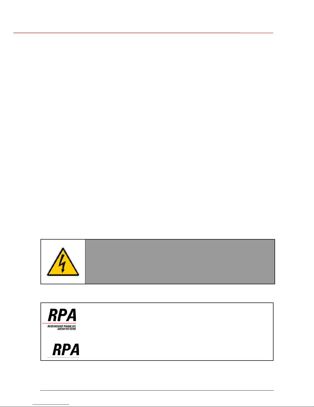
WARNING !
The UPS contains hazardous voltages.
Observe carefully the safety instructions to prevent
risk of electrical shock.
Parallel version secured with RPA
When included in the text, this symbol refers to operation
needed only for parallel system
.
Page 9
g
G
E
OPM_LPS_33E_10K_30K_4CN_V010.doc 9/82 Operating Manual LP 33 / 10-20-30 kVA
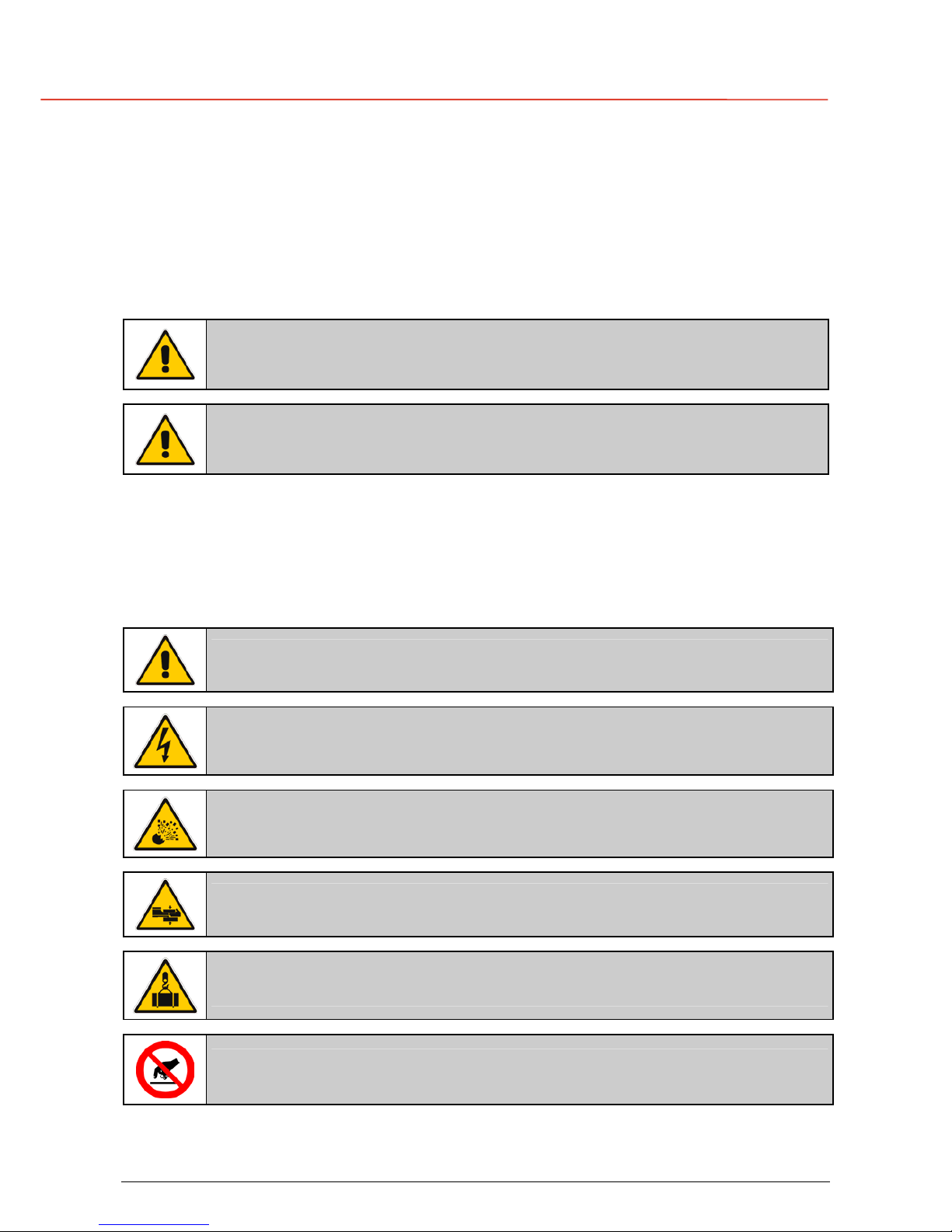
1.2 SAFETY SYMBOLS AND WARNINGS
Safety warnings
The text of this manual contains some warnings to avoid risk to the persons and to avoid damages
to the UPS system and the supplied critical loads.
The non-observance of the warnings reminding hazardous situations could result in human injury
and equipment damages.
Please pay attention to the meaning of the following warnings and symbols:
WARNING !
Referred to procedures or operations which could cause damages to the
persons or to the system, when not correctly operated.
NOTE !
Warns the user about important operations or procedures described in this
manual.
Safety symbols
When the text includes one or more of the following symbols, that means exist a potentially
hazardous situations.
Please remind the meaning of each symbol.
CAUTION
Related to all the potentially hazardous situations which may result in injury.
DANGER OF PARTS ELECTRICALLY LIVE
Related to all the situation with potentially hazardous voltage.
DANGER OF EXPLOSION
Used to indicate conditions where exploding parts can cause serious injury.
DANGER OF CRUSHING
Used when moving the equipment due to the heavy weight.
DANGER OF OVERHUNG LOAD
Used when the equipment is lifted by a crane.
DO NOT TOUCH
Risk of parts with hazardous voltages or parts in movement.
Page 10
g
G
E
OPM_LPS_33E_10K_30K_4CN_V010.doc 10/82 Operating Manual LP 33 / 10-20-30 kVA
2 INTRODUCTION
2.1 GENERAL DESCRIPTION
The LP 33 Uninterruptible Power Supply (UPS) provides the energy supply for critical loads which
need a reliable, continuous free from voltage disturbances and frequency fluctuations supply.
In case the mains fails, or it exceeds the permitted tolerances, the energy to supply the load is
furnished by the battery with a backup time dependent on its capacity, until the mains recovers.
LP 33 is a truly On-line double conversion Uninterruptible Power Supply (UPS),
equipped with automatic bypass, where the load is normally supplied by the
inverter.
LP 33 can be configured, if chosen, for the IEM mode (Intelligent Energy
Management) permitting the maximum energy saving.
The main typical performances of the LP 33 system are the following:
• On-line double conversion technology to provide an excellent quality power supply.
• Input power factor 1.
• Input current THD 8%.
• Automatic bypass and manual bypass to improve reliability and maintenance.
• Microprocessor controlled supervision.
• Dual AC inputs (optional).
• IEM mode operation (Intelligent Energy Management).
• Compact and agreeable design expressly conceived for “Office environment”.
• Low level acoustic sound, 50 dB (A) (10 and 20kVA) and 55 dB (A) (30kVA), to avoid
noise to the persons operating in the same environment.
• Multi-language LCD screen.
• Total battery management: SBM (Superior Battery Management)
• High battery capacity, 25 minutes (10 kVA) and 10 minutes (20 and 30 kVA), with battery
housed in the UPS cabinet.
• Wide rectifier input voltage tolerance: 324 ÷ 478 VAC (phase - phase).
• Wide rectifier input frequency tolerance: +/-10% (45 ÷ 55 for 50 Hz and 54 ÷ 66 for 60 Hz).
• RPA (Redundant Parallel Architecture) up to 4 units.
• GE Connectivity.
• Compliance with European standard 50091-2.
Page 11
g
G
E
OPM_LPS_33E_10K_30K_4CN_V010.doc 11/82 Operating Manual LP 33 / 10-20-30 kVA
3 DESCRIPTION
3.1 PRINCIPAL DIAGRAM AND MAIN ELEMENTS DESCRIPTION
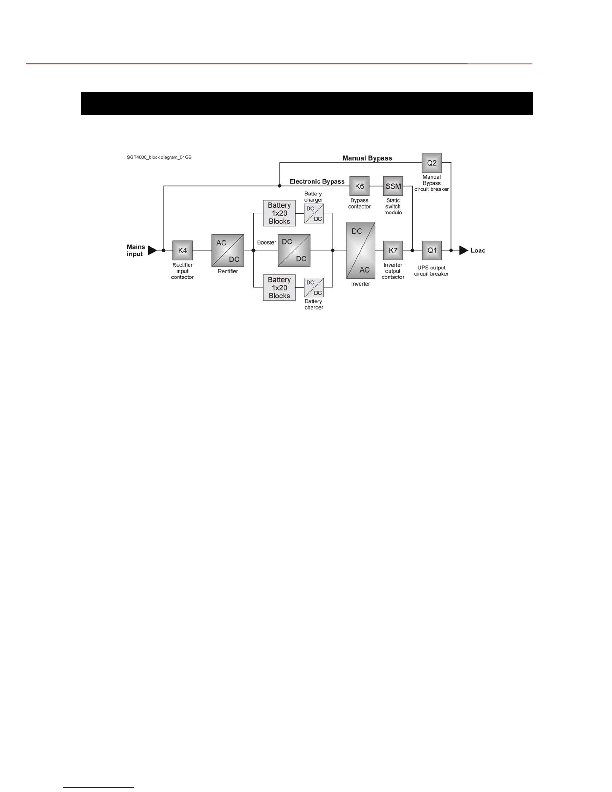
Fig. 3.1-1 UPS principal diagram
The Uninterruptible Power Supply System LP 33 / 10 - 20 - 30 kVA can be divided into the following
main elements:
Electronics
The UPS is designed with a microprocessor–controlled supervision and diagnostic system.
Communication between user and UPS is achieved by the front panel consisting of an LCD
screen, displaying the operation modes, the measurements and the events / alarms.
Rectifier
The rectifier converts the 3-phase mains voltage into a controlled and regulated DC-voltage, in
order to supply power to the booster, and to charge the battery through the battery-charger.
Inverter
The inverter converts the DC voltage into a three-phase AC-voltage with constant amplitude and
frequency, which is completely independent from the AC-input voltage.
Automatic Bypass
The automatic bypass consists of a static semiconductor-switch (SSR: Static Switch Relay), used
to provide an uninterrupted transfer of the load from inverter to mains when operating in On-line
mode.
If chosen the IEM mode, the SSM transfer the load from mains to inverter in case the utility fails.
Back-Feed Protection
All LP 33 UPS’s are equipped with an automatic system for the protection against voltage back
feeding towards Utility, through the Bypass (Applied Standard IEC 62040-1).
This protection works automatically by opening contactor K6 (in series with the thyristors of the
static switch) and eventually K7, and acts in case of internal defects of the system, or due to wrong
manipulations on the maintenance bypass Q2.
Manual Bypass
The manual bypass consists of a pair of manual switches Q1 and Q2, which allow the isolation of
the UPS from the load, while still supplying the load with power directly from the mains.
Battery
The battery, normally stored by the battery-charger, supplies the DC energy to inverter in the
event of mains failure.
Page 12
g
G
E
OPM_LPS_33E_10K_30K_4CN_V010.doc 12/82 Operating Manual LP 33 / 10-20-30 kVA
3.2 OPERATION MODES
This section describes the different possible operation modes of the UPS explaining the function of
the main modules of the UPS.
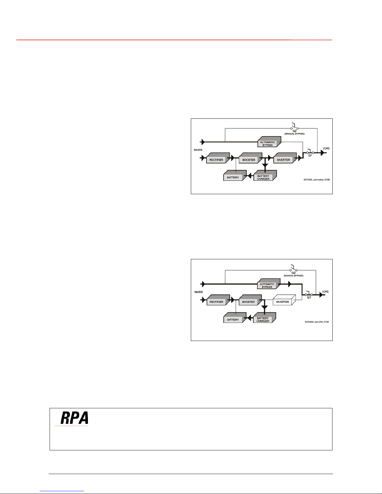
On-line mode operation
Under normal conditions the load is
permanently powered by the inverter with
constant amplitude and frequency.
The rectifier, powered by the mains, supplies
the inverter and the battery-charger keeps
the battery fully charged.
Fig. 3.2-1 Energy flow in On-line mode operation
The inverter converts the DC voltage in a new AC sine wave voltage with constant amplitude and
frequency independently from the input mains power.
IEM mode operation (Intelligent Energy Management)
When the IEM mode is selected, and the
mains power is available, the load is normally
powered through the automatic bypass.
When the mains voltage is detected out of the
prescribed tolerances, the load is
automatically transferred to the inverter.
When the mains recovers, the load returns to
the automatic bypass after a variable time
defined by the control unit.
Fig. 3.2-2 Energy flow in IEM mode operation
The IEM mode can be configured directly by the user for higher efficiency, considering the mains
reliability and criticality of the load.
The selection between the two operation modes “On-line mode and IEM mode”, or switching
between operation modes at required time, can be done through the UPS console panel (see
Section 7.3.1-5).
In case of parallel system
IEM mode (Intelligent Energy Management) cannot be enabled for RPA Parallel System.
Page 13
g
G
E
OPM_LPS_33E_10K_30K_4CN_V010.doc 13/82 Operating Manual LP 33 / 10-20-30 kVA
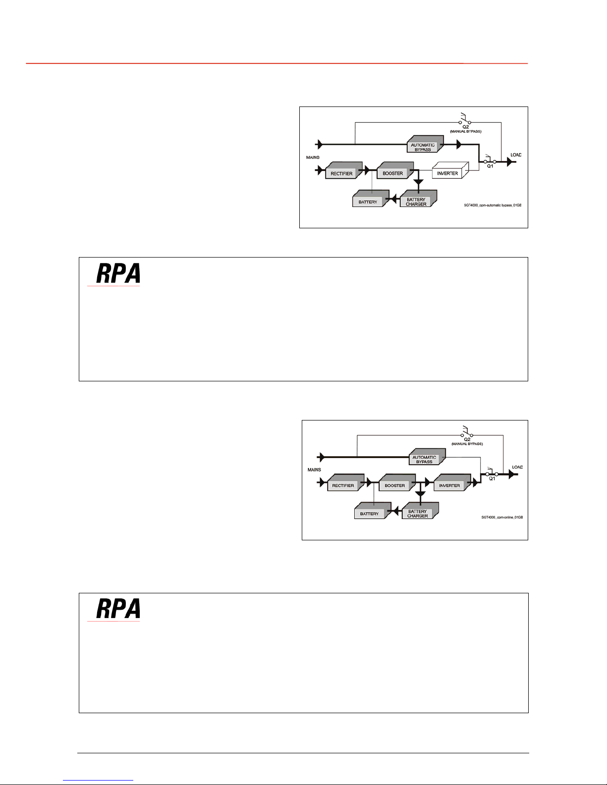
Automatic bypass operation
In On-line operation mode, the load is
permanently supplied by the inverter but, in
case of trouble on the inverter, or when
overload or short-circuit on the output occur, if
the mains voltage do not exceed the admitted
tolerances, the load is instantly transferred to
the mains through the automatic bypass,
taking advantage of the higher short circuit
power.
Fig. 3.2-3 Energy flow in automatic bypass operation
When the inverter recovers, the load will be re-transferred automatically to the inverter.
In case of parallel system
Each unit has its own bypass.
All the bypasses in the system work together, their control being managed in the same manner
by all units.
The units are continuously exchanging information before taking such decision.
In case the inverter of one unit fails, its bypass remains operating.
It is excluded only if the unit is separated from the common bus by opening its output switch Q1.
Mains recovery operation
As soon as the mains recovers, the rectifier
starts up automatically supplying the inverter
and the battery-charger recharges the
battery.
In case the inverter has been shut down
following a complete discharge of the battery,
when the mains recovers the system start up
automatically.
Fig. 3.2-4 Energy flow at mains recovery operation
When the energy stored in the battery is sufficient to ensure a minimum time of operation with the
actual load, in case of a future mains failure, the load will be retransfered to inverter (if selected
On-line mode).
In case of parallel system
When the AC input power recovers, the rectifiers will start up sequentially according to their
number in the parallel system in order to avoid an initial inrush current.
The inverters will start up automatically, but only when the battery has recharged enough
for a minimum runtime with the present load.
When enough inverters to supply the load have been restarted, the load will be transferred
from the automatic bypass back to the inverter busbars.
Page 14
g
G
E
OPM_LPS_33E_10K_30K_4CN_V010.doc 14/82 Operating Manual LP 33 / 10-20-30 kVA
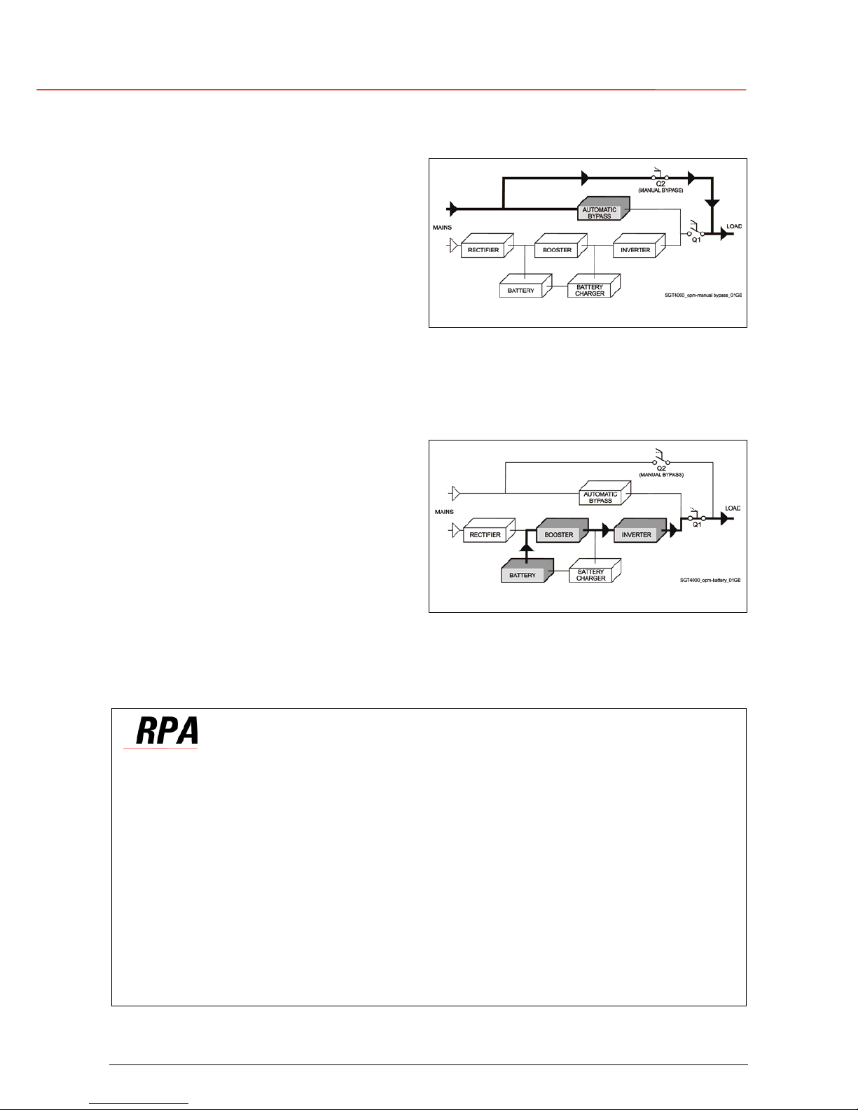
Manual bypass operation
The manual bypass circuit consisting of Q1
and Q2 manual switches, permits the transfer
of the load directly to the mains without
interruption, leaving the UPS galvanically
separated from the output load.
This type of operation is normally used when
the UPS system must be completely turned off
for maintenance or reparation.
Fig. 3.2-5 Energy flow in manual bypass operation
Mains failure operation
In the event of a mains power failure, the
rectifier and the battery-charger turn OFF,
while the inverter continues to supply the
load without interruption using the energy
stored in the battery.
During the battery discharge, the LCD screen
displays the remaining autonomy, based on
the battery capacity and the applied load.
Fig. 3.2-6 Energy flow during mains failure operation
In the event of an extended mains failure, before the battery is fully discharged, the alarm “stop
operation” warns the user that the UPS will start the shutdown procedures when the indicated
time expired (normally 3 minutes).
In case of parallel system
With parallel system for power capacity:
• With the bypass mains power available as the warning “battery low” occurs on one unit,
after timeout (selectable) the load is transferred to mains.
• With missing bypass mains power as the warning occurs on one unit, the system starts the
timeout (selectable) of “Stop operation” and then the output load shuts down.
With redundant parallel system:
• As the warning battery low occurs on one unit unnecessary to support the present load, after
timeout (selectable) this unit shuts down and the load is shared between the other units.
As the warning occurs on one unit necessary to support the present load, the system starts
the timeout (selectable) of “stop operation” and then the output load shuts down.
Page 15
g
G
E
OPM_LPS_33E_10K_30K_4CN_V010.doc 15/82 Operating Manual LP 33 / 10-20-30 kVA
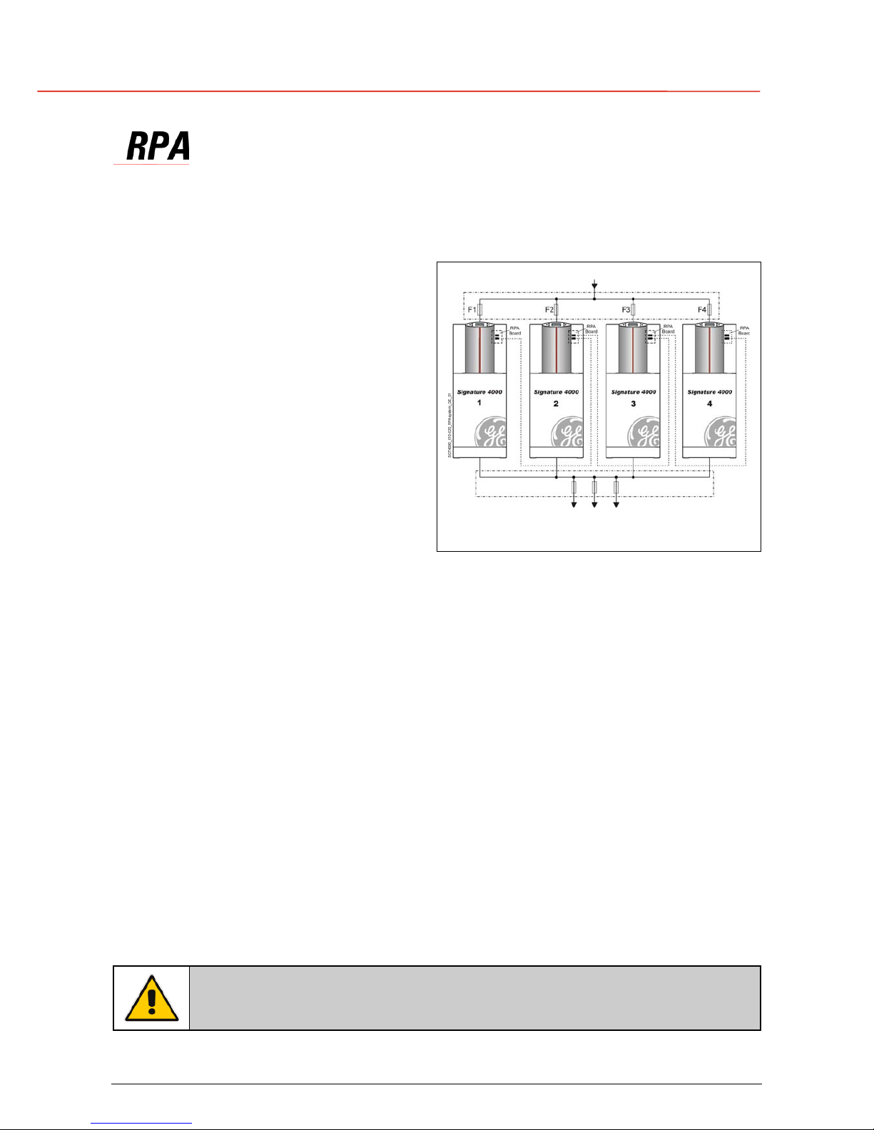
3.3 RPA PARALLEL SYSTEM
The RPA (Redundant Parallel Architecture) allows to extend the unit to a parallel system with 2, 3,
or 4 units LP 33 connected on the same bus, which ensure the highest reliability rate and increase
the power availability.
Parallel system for power capacity
Two or more units can be paralleled in order to
achieve output power superior to the maximum
power delivered by a single UPS unit.
The maximum total load shared between the n
parallel units can achieve the 100% of the
installed nominal power system.
In the event of one unit fails, the load will be
suddenly transferred to the mains by the
bypass.
Parallel system for rendundancy
The parallel system can be defined redundant
only in case the nominal power rating of n-1
units of n parallel units is sufficient to supply the
required load power.
Mains Input
Load
Fig. 3.3-1 RPA system diagram
The load in a parallel redundant system, is equally shared by n units connected on the output bars.
Should one of the parallel units trip off-line, the remaining (n-1) units will share the load maintaining
the applications protected by inverter until the normal situation restores.
Load sharing between parallel units
The control bus exchanging the data between the microprocessors of the paralleled units provide
for a constant proportional load sharing in every load condition.
Management and synchronisation of the parallel system
All the units are identical without master and slaves.
One unit is arbitrarily selected as the reference (the first unit connected on power bus) being this
unit the first synchronised with the mains voltage, and all the other units synchronise with the first
one.
In case the reference unit fails or it is excluded from the parallel power bus any other unit will take
over the reference role.
The AC input power source of all the bypasses must be the same for all the units of the parallel
system excluding any phase shift between them.
Control bus of the parallel system
A high-speed serial bus, guarantees communication, synchronization and load sharing between
the UPS modules.
Each module controls it’s own function, while the Master (each unit can be Master) controls and
commands the status of the system.
The parallel system exclude more rectifiers connected on common battery.
No transformers, fuses or automatic circuit breakers should be inserted
between the unit’s output and the load common busbars.
Page 16
g
G
E
OPM_LPS_33E_10K_30K_4CN_V010.doc 16/82 Operating Manual LP 33 / 10-20-30 kVA
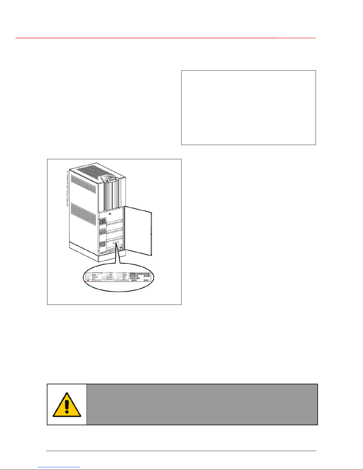
3.4 SERVICE AND TECHNICAL SUPPORT
For any request of technical support please
contact the supplier who provided the system.
Stamp of your Dealer or local responsible of the Technical
Assistance (see page 3)
Fig. 3.4-1 Identification label
The requested data permitting to identify your
UPS are marked on the identification label
fixed on the front of the cabinet, behind the
lower front door.
For fast and efficient Technical Support
solutions, please mention the data marked on
the identification label.
3.5 WARRANTY
GE, operating through its authorised agents, warrants that the standard products will be free of
defects in materials and workmanship for a period of 24 months (12 months for battery), after the
date of the invoice, or such other period as may be specified.
NOTE !
This warranty does not cover failures of the product which result from
incorrect installation, misuse, alterations by persons other than authorised
agents, or abnormal working conditions.
Page 17
g
G
E
OPM_LPS_33E_10K_30K_4CN_V010.doc 17/82 Operating Manual LP 33 / 10-20-30 kVA
3.6 RECYCLING AT THE END OF SERVICE LIFE
NOTE !
This product has been designed to respect the environment, using materials
and components respecting eco-design rules.
It does not contain CFCs (Carbon Fluor Clorid) or HCFCs (Halogen Carbon
Fluor Clorid).
GE, in compliance with environment protection recommends to the
User that the UPS equipment, at the end of its service life, must be
recovered conforming to the local applicable regulations.
WARNING !
Leads contained in the batteries is a dangerous substance for the
environment, therefore it must be correctly recycled by specialised
companies!
Page 18
g
G
E
OPM_LPS_33E_10K_30K_4CN_V010.doc 18/82 Operating Manual LP 33 / 10-20-30 kVA
4 INSTALLATION
4.1 TRANSPORT
The UPS is fixed on transport socket suitable for forklift, which include a special layer of Ethafoam
to protect the equipment against the transport shock.
Normally the UPS is packaged with carton box.
On request the equipment can be packaged in wooden case.
Move the UPS in its original package to the final destination room.
Do not stack other package on top: they could damage the upper side of the cabinet.
NOTE !
When moving the UPS, pay attention to:
FRAGILE
SENSITIVE
TO DAMPNESS
TO HEAT
SENSITIVE
TO FROST
SENSITIVE
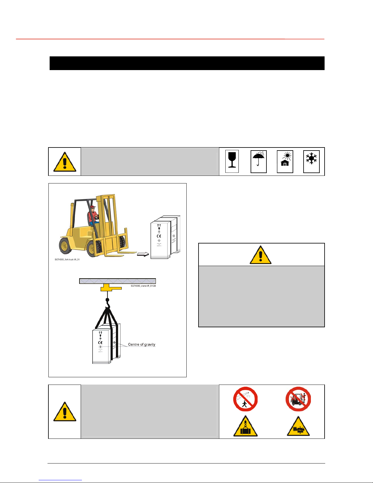
Forklift
The UPS may be lifted with a forklift in
upright position from right and left side.
Take note of the centre of gravity marked on
the package.
NOTE !
Check for sufficient floor and elevator
loading capacity.
Transport UPS only in upright position.
Do not stack other package on top of
the UPS.
Forklift
Crane
Fig. 4.4-1 LP 33 lifting
Crane
If the UPS has to be lifted by crane, use
suitable carrying belts taking note of the
centre of gravity marked on the package.
WARNING !
When loading / downloading and when
moving the UPS, it is forbidden:
When loading / downloading and when
moving the UPS, pay attention to:
Page 19
g
G
E
OPM_LPS_33E_10K_30K_4CN_V010.doc 19/82 Operating Manual LP 33 / 10-20-30 kVA
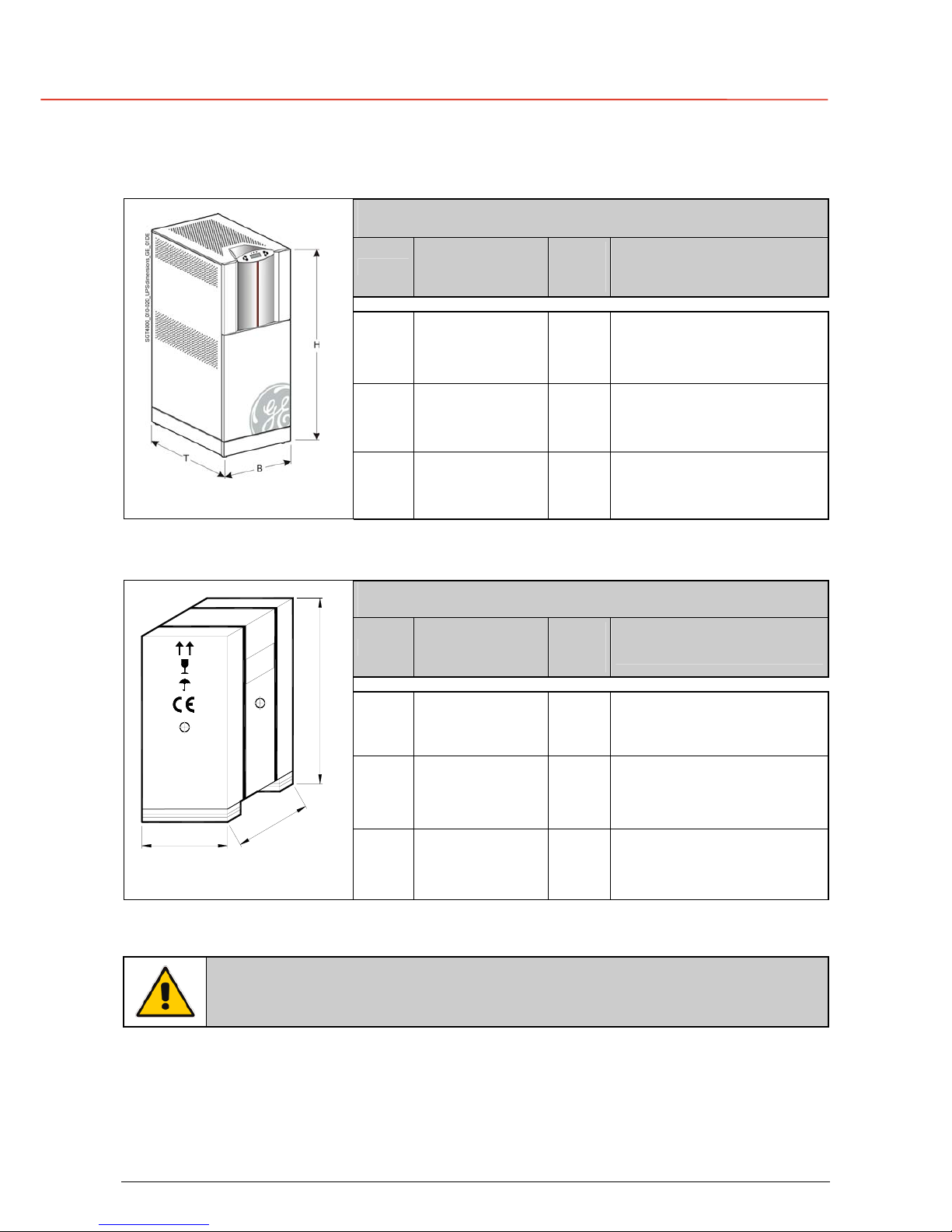
4.1.1 Dimensions and weight
Dimensions and weight LP 33
UPS
Dimensions
(W x D x H)
Weight
without
battery
Weight with
standard battery
10 kVA
500 x 780 x 1310 mm
19.7” x 30.7” 51.58”
135 Kg
298 lbs
269 (7Ah) / 367 (14Ah) Kg
594 (7Ah) / 810 (14Ah) lbs
20 kVA
500 x 780 x 1310 mm
19.7” x 30.7” 51.58”
147 Kg
325 lbs
379 (14Ah) Kg
836
(14Ah) lbs
Fig. 4.1.1-1 Dimensions LP 33
30 kVA
660 x 780 x 1310 mm
19.7” x 30.7” 51.58”
185 Kg
408 lbs
533 (21Ah) Kg
1’176 (21Ah) lbs
Dimensions and weight with carton package (standard)
UPS
Dimensions
(W x D x H)
Weight
without
battery
Weight with
standard battery
10 kVA
630 x 890 x 1580 mm
24.8” x 35.1” x 62.2”
165 Kg
364 lbs
299 (7Ah) / 397 (14Ah) Kg
660 (7Ah) / 876 (14Ah) lbs
20 kVA
630 x 890 x 1580 mm
24.8” x 35.1” x 62.2”
170 Kg
375 lbs
402 (14Ah) Kg
887 (14Ah) lbs
SGT4000_dimensions packing_01 IT
CENTER
of
GRAVITY
C
E
N
T
E
R
o
f
G
R
A
V
I
T
Y
H
T
B
Fig. 4.1.1-2 Dimensions with
carton package
30 kVA
790 x 890 x 1580 mm
31.1” x 35.1” x 62.2”
200 Kg
441 lbs
548 (21Ah) Kg
1’209 (21Ah) lbs
NOTE !
The weight of each single piece is marked outside the package!
Page 20
g
G
E
OPM_LPS_33E_10K_30K_4CN_V010.doc 20/82 Operating Manual LP 33 / 10-20-30 kVA
4.2 DELIVERY
When delivered, check carefully the package integrity and the physical conditions of the UPS
equipment.
In case of any damage sustained during transport, immediately inform the carrier and contact your
local Service Centre.
A detailed report of the damage is necessary for any insurance claim.
NOTE !
A damaged UPS must never be installed or connected to mains or battery!
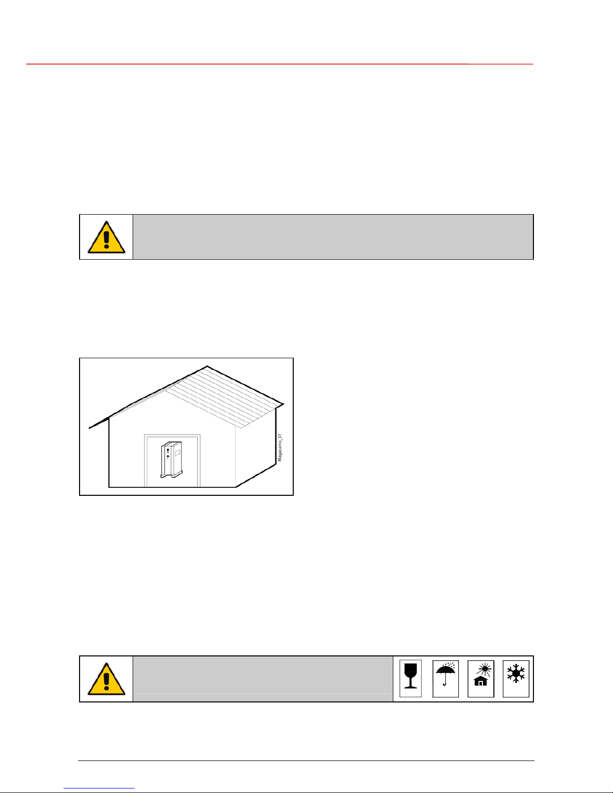
4.3 STORAGE
The equipment is carefully packed for
transport and storage so that it is in a perfect
condition when eventually installed.
Never leave an UPS outside the building and
do not store the UPS one on top of the other.
It is recommended to store the UPS in its
original package in a dry, dust free room
and far away from chemical substances,
with temperature not exceeding -25°C to
55°C (-13°F to 131°F).
4.3.1 Storage of the UPS
Some important functions of the UPS, such as the customised functions, are defined by
parameters stored in a RAM memory.
The RAM is supplied by a small backup battery located on the Control Unit board.
If the storage time of the UPS exceeds 1 year, these functions should be verified by an
authorised Service Centre before putting the UPS into operation.
NOTE !
In case of storage of the UPS pay attention to:
FRAGILE
SENSITIVE
TO DAMPNESS
TO HEAT
SENSITIVE
TO FROST
SENSITIVE
Page 21
g
G
E
OPM_LPS_33E_10K_30K_4CN_V010.doc 21/82 Operating Manual LP 33 / 10-20-30 kVA
4.3.2 Storage of the battery
In case of extended storage, when the delivery includes maintenance free batteries, keep in mind
that they are subject to auto-discharging process
To avoid permanent damages to the battery, you must observe the following instructions:
• The storage time without charging the battery depends on the temperature of the storage
ambient.
• The optimal ambient temperature for the batteries is 20°C (68°F).
For storage temperature higher than 20°C (68°F), the storage time will decrease.
• Each additional 10°C (18°F) over the nominal temperature of 20°C (68°F) will decrease the
storage time, without freshening charge, by half.
In case of a maintenance free battery, the storage time without charging the battery is
approximately:
6 months with storage temperature 20°C (68°F)
3 months with storage temperature 30°C (86°F)
2 months with storage temperature 35°C (95°F)
NOTE !
In case of battery storage pay
attention to:
FRAGILE
SENSITIVE
TO DAMPNESS
TO HEAT
SENSITIVE
TO FROST
SENSITIVE
Page 22
g
G
E
OPM_LPS_33E_10K_30K_4CN_V010.doc 22/82 Operating Manual LP 33 / 10-20-30 kVA
4.4 PLACE OF INSTALLATION
The UPS should be installed in a restricted area where only qualified personnel should be
admitted.
The place of installation should be clean, dust-free, and provided with proper ventilation or air-
conditioning.
Verify for sufficient floor load capacity (see Section 4.1.1).
We strongly advice that the ambient temperature should not exceed 20°÷25°C / 68°÷77°F (max.
35°C / 95°F).
See Section 4.5.
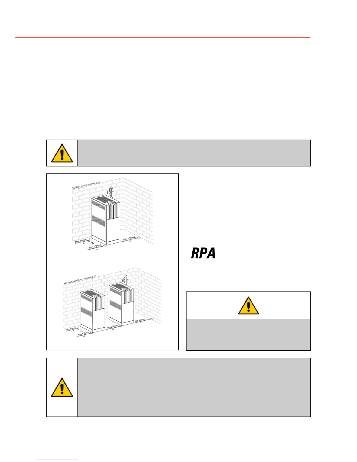
NOTE !
Insufficient space on both sides of the UPS in respect to the wall can cause a
dangerous increase of the internal operating temperature.
LP 33 positioning
For easier access in case of maintenance
operation and for a free circulation around the
cabinet, we recommend to maintain the
following minimum distances:
Right & left side: 100 mm (4”)
Rear side: 50 mm (2”)
Top of the UPS: 300 mm (12”)
Right & left side: 200 mm (8”)
Rear side: 50 mm (2”)
Top of the UPS: 300 mm (12”)
Fig. 4.4-1 LP 33 positioning
Fig. 4.4-2 RPA parallel system positioning
NOTE !
Both lateral sides of the UPS MUST BE
ACCESSIBLE at any time for repair or
maintenance.
NOTE !
Operating temperature is very important for valve regulated battery
(maintenance free).
Operation at temperatures higher than 20°C (68°F) will reduce life expectancy.
Respect the prescription VDE 0510, those of the battery supplier and other
local standards.
The installation and cabling of the battery must be done by qualified people.
Page 23
g
G
E
OPM_LPS_33E_10K_30K_4CN_V010.doc 23/82 Operating Manual LP 33 / 10-20-30 kVA
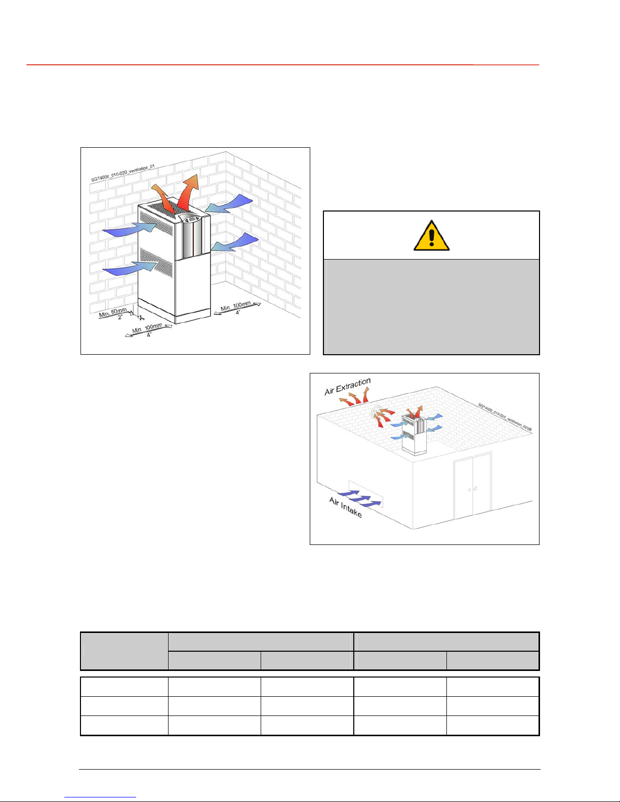
4.5 VENTILATION AND COOLING
The heat produced by the UPS is transferred to the environment by its internal blowers.
Airflow through the UPS
It is important that the cooling air can freel
y
flow through the air inlets and outlets of the
UPS.
Fig. 4.5-1 Airflow through the LP 33
NOTE !
Insufficient distances on both sides of
the UPS could increase the temperature
inside the UPS.
Do not put any object on the top of the
cabinet: it might obstruct the air flow.
Heat evacuation from UPS room
The heat must be evacuated from the
environment with a proper cooling / ventilation
system provided by the user.
Fig. 4.5-2 Heat evacuation from UPS room
Air volume and losses of the UPS
The approximate minimum air volume needed to evacuate the heat generated by the UPS, for
inlet temperature max. 35°C (95°F), for the standard version at inverter nominal load with PF =
0.8 lag. and battery charged, are the following:
Air volume Losses
UPS model
On-line mode IEM mode On-line mode IEM mode
LP 33 / 10 kVA
250 m
3
/h 50 m3/h 0.79 kW 0.16 kW
LP 33 / 20 kVA
500 m
3
/h 100 m3/h 1.58 kW 0.33 kW
LP 33 / 30 kVA
700 m
3
/h 150 m3/h 2.37 kW 0.49 kW
Page 24
g
G
E
OPM_LPS_33E_10K_30K_4CN_V010.doc 24/82 Operating Manual LP 33 / 10-20-30 kVA
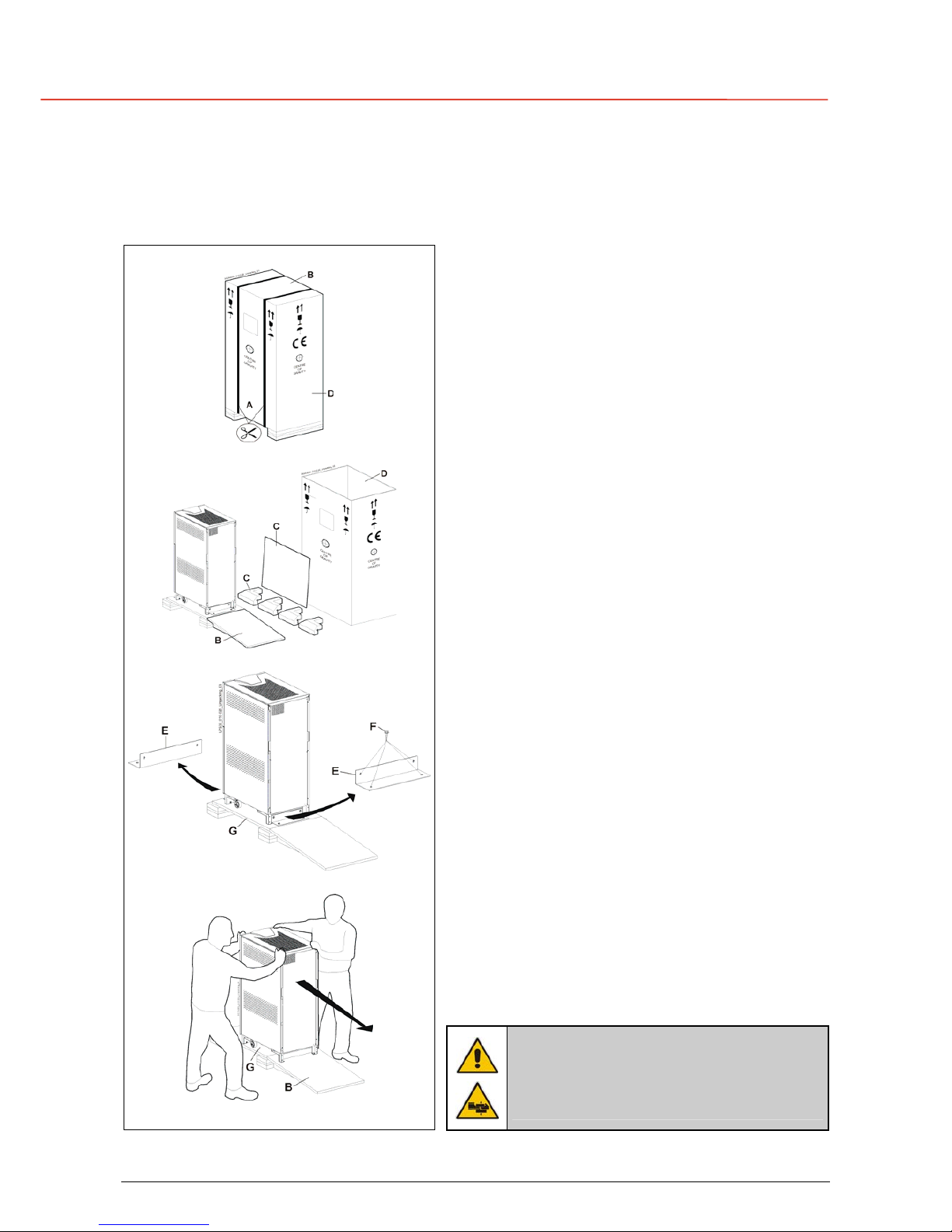
4.6 UNPACKING
Move the equipment in it’s original packing, carton box or wooden case, until the place of
installation and remove the packing and the transport sockets only just before installing the UPS.
1
Procedure for the unpacking of the UPS:
• Make sure to have sufficient space around the
UPS before you start unpacking.
• Cut the two straps “A” fixing the carton box.
2
• Remove the wooden top cover “B”, which will be
used as a ramp and position it as shown in the
picture.
• Remove the protection “C” outside the cabinet
and the accessories bag.
• Remove the carton box “D”.
3
• Remove the 2 angle irons “E”, which are fixing the
UPS to the wooden base “G” by unscrewing bolts
“F”.
4
• Push now the UPS towards the ramp “B” and let it
slide down the ramp.
This has to done with the utmost care!
Fig. 4.6-1 LP 33 unpacking sequence
NOTE !
Be aware of the heavy weight of the
UPS, in particular if already equipped
with Batteries.
Page 25
g
G
E
OPM_LPS_33E_10K_30K_4CN_V010.doc 25/82 Operating Manual LP 33 / 10-20-30 kVA
Included in the delivery you can find the following parts:
• An accessories bag.
• Control Bus cables (only for RPA system).
• 2 bolts to support the UPS cabinet (see Fig. 4.6-2).
• CD-ROM connectivity.
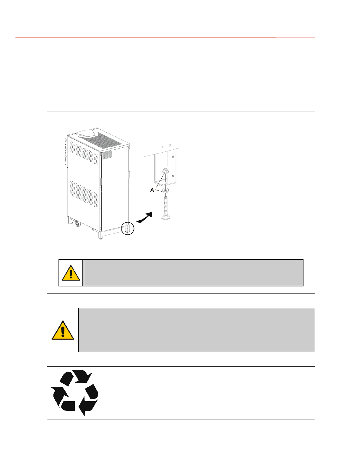
Bolts to block and support the LP 33
Fig. 4.6-2 Bolts to block the LP 33 on it’s position
Make use of the 2 bolts, as shown in the
picture, in case you desire to block the
UPS on it’s position.
The bolts can be used either on the front
or the rear of the UPS.
The height can be adjusted with the 2
enclosed nuts “A”, taking care however,
that the weight of the UPS remains on the
wheels.
The UPS can also be screwed directly to
the floor on each leg.
NOTE !
The wheels are designed only for limited movements on the installation
site.
NOTE !
A damaged UPS must never be installed or connected to mains or battery!
In case of any damage sustained during the transport, immediately inform the
shipping agent!
A detailed report of the damage is necessary for any indemnity claim.
Packing material recycling
GE, in compliance with environment protection, use only environmentally
friendly material.
UPS packing materials must be recycled in compliance with all applicable
regulations.
Page 26

g
G
E
OPM_LPS_33E_10K_30K_4CN_V010.doc 26/82 Operating Manual LP 33 / 10-20-30 kVA
4.7 CABLING
WARNING !
The connections to and from the UPS must be executed by QUALIFIED
PERSONNEL ONLY.
Refer to the “Safety prescriptions - Installation” described on page 7.
The cabling of the UPS-system has to be done according to the power installed.
Exceptions are only allowed to suit local prescriptions.
For correct rating of fuses and cable sections for input mains, output load and battery, see data
indicated in sections 4.7.2 and 4.7.3.
Before connecting the UPS, verify that the mains voltage and frequency, the output load voltage,
the frequency and the battery data (cells number, floating voltage, autonomy) are according to the
local requirements.
Caution when using four-pole circuit breakers as protection.
A potential problem exists for situations with non-linear loads: the neutral current could be
greater than the phase currents.
Avoid to run the input cables in parallel with the output cables to prevent them from noise
induction.
Mains Input
Load
Fig. 4.7-1 RPA Parallel System
In order to ensure a correct load sharing between
the parallel units, when the load is supplied by
mains, it is recommended to keep the cable size
and length from the input distribution board to the
output busbar the same for each parallel unit.
Mains Bypass input voltage must be the same for
all units, thus avoiding phase shift or phase
rotation problems.
To avoid mutual induction effect, the input cables
bust be run in separate conduit from the output
cables.
No transformers, fuses or automatic circuit breakers should be
inserted between the unit’s output and the load common busbars.
The delivery and installation of fuses and input / output connections of the UPS are at the
customer’s expense, unless agreed otherwise.
NOTE !
In case of non observance of the required minimum distances on both UPS
sides (see section 4.4) it is recommended to provide an additional length of
the input/output cables so that the UPS can be moved for maintenance
purpose.
It is recommended to use flexible input/output conductors with suitable length
to admit a sufficient displacement.
Page 27

g
G
E
OPM_LPS_33E_10K_30K_4CN_V010.doc 27/82 Operating Manual LP 33 / 10-20-30 kVA
4.7.1 Fuse discrimination (co-ordination of breakers tripping)
In order to ensure the circuit selectivity in case of short- circuit at load level, special care must
be taken in choosing the fuse ratings installed in the output distribution.
When a short-circuit on the output occurs, if the mains voltage does not exceed the admitted
tolerances, the load is instantly transferred to the mains through the automatic bypass, taking
advantage of the higher short circuit power.
To ensure a correct co-ordination of the breakers tripping, the fuses supplying the bypass line must
be at least 1,6 time bigger than the largest fuse in the output distribution.
If the selectivity must be ensured also in case of mains failure (that means inhibit automatic
bypass), the largest fuse in the output distribution must be lower than 20% of the UPS rated
current for each phase.
Page 28

g
G
E
OPM_LPS_33E_10K_30K_4CN_V010.doc 28/82 Operating Manual LP 33 / 10-20-30 kVA
4.7.2 Fuse ratings
Fig. 4.7.2-1 Mains input and battery fuses
LP 33 fuses
The UPS is equipped with rectifier input fuses
F1, F2, F3 and battery fuses F9, F10, F11.
In case of replacement the same type and the
same rating must be used (see table below).
Fuses type URD 660/690V Fuses type gG-gL 660/690V
UPS model
F1 - F2 - F3 F9 - F10 - F11
LP 33 / 10 kVA 20A (14 x 51) 25A (14 x 51)
LP 33 / 20 kVA 40A (14 x 51) 50A (14 x 51)
LP 33 / 30 kVA 63A (22 x 58) 80A (22 x 58)
Required protective devices
If ELCB breakers are prescribed to protect the input connections, consider the high leakage current
towards the earth generated by the noise-suppressor capacitors.
If strongly prescribed, the ELCB breakers should be the largest type suitable for non-linear current
and for delayed operation.
Fig. 4.7.2-2 Common input mains
Fig. 4.7.2- Separated input mains (option)
Fuses (gL) or Circuit Breakers rating
for AC input 3x380/220V, 3x400/230V, 3x415/240V
UPS model
F1 F2 F3
F4 (external battery)
LP 33 / 10 kVA 3 x 25A 3 x 25A 3 x 20A 2 x 25A
LP 33 / 20 kVA 3 x 50A 3 x 50A 3 x 35A 2 x 50A
LP 33 / 30 kVA 3 x 63A 3 x 63A 3 x 50A 2 x 80A
Page 29

g
G
E
OPM_LPS_33E_10K_30K_4CN_V010.doc 29/82 Operating Manual LP 33 / 10-20-30 kVA
4.7.3 Input / output cable ratings
Cable sizes indicated below, do not consider eventual line voltage drop.
NOTE !
The values given in the tables below do correspond to European Standards
(EN) and, in brackets, for Swiss standards (SEV/ASE).
In any case the local standards must be respected.
Fig. 4.7.3-1 Common input mains
Fig. 4.7.3-1 Separate input mains (option)
Recommended sizing for the lines A, B, C, D, E (mm2)
According to European Standards EN and Swiss standard SEV/ASE (in brackets)
UPS model
A and B C D E K
LP 33 / 10 kVA
5x4 (5x6) 5x4 (5x6) 4x2.5 (4x4) 5x2.5 (5x4) 4x2.5 (4x4)
LP 33 / 20 kVA
5x10 (5x16) 5x10 (5x16) 4x6 (4x10) 5x6 (5x10) 4x6 (4x10)
LP 33 / 30 kVA
5x10 (5x16) 5x10 (5x16) 4x10 (4x16) 5x10 (5x16) 4x10 (4x16)
NOTE !
According to EMC standards, the connection between the UPS and an
external battery must be done using a shielded cable!
Page 30

g
G
E
OPM_LPS_33E_10K_30K_4CN_V010.doc 30/82 Operating Manual LP 33 / 10-20-30 kVA
4.8 CONNECTIONS
WARNING !
The connections to and from the UPS must be executed by QUALIFIED
PERSONNEL ONLY.
Refer to the “Safety prescriptions - Installation” described on page 7.
4.8.1 Common input mains
Fig. 4.8.1-1 Common input mains
Common input mains
The UPS delivered in standard version has
common input mains.
Only one input line (F1) supplies both rectifier
and bypass input terminals.
Bear in mind that when the mains fuses are
opened there is a supply failure to the rectifier
as well as to the automatic bypass and manual
bypass.
Access to the AC terminals
1 - Open the front door “A” of the cabinet.
2 - Remove the front panel “B”
loosening the screw “F”.
3 - Remove the front panel protection cover
“C” by pulling it off.
4 - Remove the left side panels “D and E”
loosening the screws “G”.
NOTE !
For UPS correct operation,
the input mains phase
rotation must be clock-wise.
SGT4000_010-020_UPS connection_02
A
B
C
D
E
G
F
Fig. 4.8.1-2 Power IN / OUT connections
Input mains connection
L1 = Phase L1 rectifier + bypass
L2 = Phase L2 rectifier + bypass
L3 = Phase L3 rectifier + bypass
N1 = Neutral mains PE = Earth
Output load connection
L1 = Phase L1 load
L2 = Phase L2 load
L3 = Phase L3 load
N2 = Neutral load PE = Earth load
SGT4000_010-020_connec tion common_01GB
O
u
t
p
u
t
L
o
a
d
I
n
p
u
t
M
a
i
n
s
Fig. 4.8.1-3 Common input mains connection
NOTE !
Input/output terminals must be
tightened with a proper
screwdriver applying torsion
force 1,2 / 1,4 Nm.
Clamp the input/output cables
with the included cable-ties “A”.
Page 31

g
G
E
OPM_LPS_33E_10K_30K_4CN_V010.doc 31/82 Operating Manual LP 33 / 10-20-30 kVA
4.8.2 Separate input mains (option)
Fig. 4.8.2-1 Separate input mains (option)
Separate input mains
On request, the UPS can be delivered for
separate input mains.
Two independent lines (F2 and F3) supply
separately the rectifier and the bypass inputs
With this configuration, when the rectifier-input
fuses are opened, the automatic bypass and the
maintenance bypass are supplied by the other
line.
Access to the AC terminals
1 - Open the front door “A” of the cabinet.
2 - Remove the front panel “B”
loosening the screw “F”.
3 - Remove the front panel protection cover
“C” by pulling it off.
4 - Remove the left side panels “D and E”
loosening the screws “G”.
NOTE !
Neutral of rectifier input and
neutral of bypass input must be
coming from the same input bar.
Inside the UPS, neutrals N1 and
N are connected together.
SGT4000_010-020_UPS connection _02
A
B
C
D
E
G
F
Fig. 4.8.2-2 Power IN / OUT connections
SGT4000_010-020_connection s eparate_01IT
U
s
c
i
t
a
C
a
r
i
c
o
R
a
d
d
r
i
z
z
a
t
o
r
e
I
n
g
r
e
s
s
o
R
e
t
e
I
n
g
r
e
s
s
o
R
e
t
e
B
y
p
a
s
s
Fig. 4.8.1-3 Separated input mains
NOTE !
Input/output terminals must be
tightened with a proper
screwdriver applying torsion
force 1,2 / 1,4 Nm.
Clamp the input/output cables
with the included cable-ties
“A”.
Rectifier input mains connection
L1 = Phase L1 rectifier L2 = Phase L2 rectifier L3 = Phase L3 rectifier
N1 = Neutral mains PE = Earth
Bypass input mains connection
L1 = Phase L1 bypass L2 = Phase L2 bypass L3 = Phase L3 bypass
N = Neutral mains
Output load connection
L1 = Phase L1 load L2 = Phase L2 load L3 = Phase L2 load
N2 = Neutral load PE = Earth load
NOTE !
For UPS correct operation, the input mains phase rotation must be clock-wise.
Page 32

g
G
E
OPM_LPS_33E_10K_30K_4CN_V010.doc 32/82 Operating Manual LP 33 / 10-20-30 kVA
4.8.3 External battery connection
Before proceeding to an external battery connection, follow the Safety rules concerning the
battery.
Make sure that the UPS is not powered, and remove the external battery protections and the fuses
F9, F10, F11 at the front of the UPS cabinet.
ATTENTION !
Before closing the battery fuses F9, F10 and F11, verify for correct polarity of
the battery connection.
SGT4000_010-020_connection exter nal battery_01a
F
1
1
F
9
F
1
0
-
+
0
+
0
-
+
0
-
F9
F10
F11
F9 (+) = Positive pole F10 (0) = Central point of battery blocks F11 (-) = Negative pole
Fig. 4.8.3-1 External battery connection to UPS
NOTE !
Clamp the input/output cables with the included cable-ties “A”.
Page 33

g
G
E
OPM_LPS_33E_10K_30K_4CN_V010.doc 33/82 Operating Manual LP 33 / 10-20-30 kVA
4.8.4 RPA system - Control bus connection
WARNING !
This operation must be performed by trained personnel before the initial start-
up (ensure that the UPS installation is completely powered down).
Access to the RPA board
1 - Open the front door “A” of the cabinet.
2 - Remove the protection covers “B, C, D”
fixed with screws “F”.
3 - Remove the front panel protection cover “C”
by pulling it off.
SGT4000_010-020_RPA connection_01
F
A
E
D
B
F
C
F
Fig. 4.8.4-1 Access to the RPA board
NOTE !
When fixing again the protection
covers, make sure that the
screws “F” are as tight as
possible since they serve also as
earth connection.
SGT4000_010-020_RPA connection_02GB
UPS 2
P16
J3
J4
UPS 3
P16
J3
J4
P16
UPS 4
J4
J3
P2 P2 P2 P2
P15 P15 P15 P15
P16
J4
J3
UPS 1
Fig. 4.8.4-2 Bus connection RPA parallel system
Bus connection RPA parallel system
Connect the control bus cable between the parallel units as indicated in the diagram Fig. 4.8.4-2.
Provide that the connectors J3 and J4 are properly fixed with the included screws.
The jumper JP1 - JP2 - JP3 must be
removed only on the intermediate units,
where the connectors J3 and J4 are both
inserted.
Do not insert or remove J3 and J4 from
the board “P16 - Connector adapter RPA”
when the parallel system is operating.
SGT4000_010-020_RPA connection_03
JP2JP1
JP3
P16
J3
J4
Fig. 4.8.4-3 Connection to Board P16
Page 34

g
G
E
OPM_LPS_33E_10K_30K_4CN_V010.doc 34/82 Operating Manual LP 33 / 10-20-30 kVA
SGT4000_010-020_RPA connection_04GB
UPS 1
UPS 2
UPS 3
UPS 4
E
E
E
E
Fig. 4.8.4-4 Control bus location RPA parallel system
Control bus location RPA parallel system
Place the cables and connect them as indicated in the diagram Fig. 4.8.4-4 following these
procedures:
• Fix the control bus cables with the appropriate tie-wrap “E”.
• Place the cables between the parallel units in separated protected conduit to avoid they
could be accidentally interrupted.
• Put in place the front screens “B, C and D” (Fig. 4.8.4-1) paying attention to not damaging
the control bus cables.
It is important to place the units in sequence of their assigned number.
A unit number from P1 to P4, is defined by the setting of parameters and displayed on the control
panel.
This number is also marked inside and outside the packaging.
The standard length of the control bus cable between two parallel unit is 8 m / 26 ft (higher length
on request = up to 15 m / 50 ft).
Maximal overall length of bus connection, between the first and the last unit, should not be longer
than 45 m (345 ft).
Page 35

g
G
E
OPM_LPS_33E_10K_30K_4CN_V010.doc 35/82 Operating Manual LP 33 / 10-20-30 kVA
4.9 UPS FUNCTIONING AS FREQUENCY CONVERTER
When the UPS LP 33 is delivered as frequency converter (different output frequency with respect to
the input frequency), the automatic bypass and manual bypass functions are disabled.
Therefore the load cannot be transferred to mains in case of overload, short circuit, or inverter
failure.
In cases where the UPS needs to be powered down for maintenance purposes, the critical load
must also be powered down during this time.
When the set-up parameters of the UPS are set for frequency converter, the IEM mode operation
is automatically disabled.
The UPS delivered as frequency converter has the following differences:
• Automatic bypass disabled by setting of dedicated parameter (access protected by password
reserved to service engineer).
• The handle of the switch Q2 - manual bypass is removed to avoid accidental wrong
manipulations.
• Mains bypass disabled by removing the fuse F2 fitted on the board P12 - Control Interface.
WARNING !
In case a UPS delivered as frequency converter should be set on site for UPS
standard version, the operation must be performed by a qualified service
engineer.
Notices for installation:
• For UPS with common AC input follows the standard procedure described in Section 4.8.1.
• For UPS with separate AC input only the rectifier input must be powered (see Section 4.8.2)
Notices for start up procedures:
• Follow the standard procedure indicated in Section 8.1.
Notices for shutdown procedures:
• Follow the standard procedure indicated in Section 8.1.
NOTE !
The inverter can be turned off only by pressing the push-button total off.
Page 36

g
G
E
OPM_LPS_33E_10K_30K_4CN_V010.doc 36/82 Operating Manual LP 33 / 10-20-30 kVA
5 LAYOUT
5.1 LAYOUT LP 33 / 10 - 20 KVA
Fig. 5.1.1-1 General view
Fig. 5.1.1-2 Front view
Fig. 5.1.1-3 Side view
Fig. 5.1.1-4 Control panel
SGT4000_010-020_UPS without protections_01GB
SNMP Card (option)
RPA board (option)
Customer Interface (option)
Relay Card
Serial port RS232
Total Off push-button
Output switch Q2
Output switch Q1
Fuses F1-F2-F3
(Manual Bypass)
(Rectifier Input)
Fuses F9 - F10 - F11
(Battery)
Identification data label
Fig. 5.1.1-5 Front view without panels
Fig. 5.1.1-6 Power connection view
Page 37

g
G
E
OPM_LPS_33E_10K_30K_4CN_V010.doc 37/82 Operating Manual LP 33 / 10-20-30 kVA
5.2 LAYOUT LP 33 / 30 KVA
Fig. 5.2.1-1 General view
Fig. 5.2.1-2 Front view
Fig. 5.2.1-3 Side view
Fig. 5.2.1-4 Control panel
SGT4000_030_UPS without protections_01GB
SNMP Card (option)
RPA board (option)
Customer Interface (option)
Relay Card
Serial port RS232
Total Off push-button
(Manual Bypass)
Output switch Q1
Output switch Q1
Output switch Q2
(Rectifier Input)
Fuses F9 - F10 - F11
(Battery)
Identification data label
Fig. 5.2.1-5 Front view without panels
Fig. 5.2.1-6 Power connection view
Page 38

g
G
E
OPM_LPS_33E_10K_30K_4CN_V010.doc 38/82 Operating Manual LP 33 / 10-20-30 kVA
6 SYSTEM HANDLING
6.1 CONTROL PANEL
LPS33_control pa nel CN_01
Metering
Alarm
Warning
Operation
Alarm
Menu
+
Enter
Digital Energy
TM
LP Series
Fig. 6.1-1 Control panel
LCD screen
Shows the UPS system data, events messages and UPS setting.
The data is displayed on 2 rows, 20 characters each, allowing the operator to
select between 2 languages: English and Chinese.
If there is no keypad activity during 1 minute the LCD screen will return to
default screen.
Metering
Shows electric parameters, operating statistics and some information screens
(see Section 7.1).
Alarm
Shows in chronological order, all the events occurred (alarms, messages,
commands, handling, etc.) and resets general alarm / buzzer (see Section 7.2).
Menu
Allows the user to adapt certain features of the UPS to his needs, to reset the
command total off, to test the LEDs panel, and to command the inverter
ON/OFF (see Section 7.3).
+
Scroll to following screen.
Entering in PARAMETER MENU/USER, allows to select the horizontal editable
position.
-
Entering in Alarm and Metering, scroll to previous screen.
Entering in menu allows to select the row including the needed command.
Enter
Confirms the selected command.
Entering in PARAMETER MENU/USER allows the user to change the
parameters.
LED Alarm
(red)
It warns about the imminent inverter stop and the consequent load shutdown as
result of:
• the battery is fully discharged and the load cannot be transferred on mains
(default parameter = 3 min.).
• overtemperature (default = 3 min.) or overload condition (125%-10 min,
150%-1 min.) and the load cannot be transferred on mains.
LED Warning
(yellow)
When blinking, it means the UPS is in alert condition with the buzzer sounding.
The yellow LED will remain lit after pressing the key Alarm.
It remains lit also when the output switch Q1 is open.
LED Operation
(green)
When lit, it means the UPS is correctly operating and the load is powered by the
inverter. When blinking, it means SERVICE REQUIRED
Page 39

g
G
E
OPM_LPS_33E_10K_30K_4CN_V010.doc 39/82 Operating Manual LP 33 / 10-20-30 kVA
6.2 COMMAND PUSH BUTTONS AND SWITCHES
total of
f
By pressing this red button, all the contactors (K4, K6 and K7)
ill be opened.
he booster, the battery-charger and the inverter shut down.
In a parallel system pressing total off on one unit
all the units will shut down.
NOTE !
Using the command total off, the load will be
immediately powered down.
Fig. 6.2-1 Total off push button
o restart the unit, command total off must be restored
ntering the screen MENU/RESET TOTAL OFF.
Q1 - UPS output switch
Q2 – Manual bypass switch
Do not switch ON Q1 and Q2 with inverter ON.
Fig. 6.2-2 Q1 and Q2 switches
Fig. 6.2-3 Rectifier input fuses
Rectifier input fuses
Battery fuses
Fig. 6.2-4 Battery fuses
Mains failure of long duration or low Battery
voltage will cause the automatic shutdown of
the UPS, thus preventing damage to the
Battery
Page 40

g
G
E
OPM_LPS_33E_10K_30K_4CN_V010.doc 40/82 Operating Manual LP 33 / 10-20-30 kVA
7 LCD SCREEN
Shows the UPS system data, events messages and UPS setting.
The data is displayed on 2 rows, 20 characters each, allowing the operator to select between 2
languages: English and Chinese.
If there is no keypad activity during 1 minute the LCD screen will return to default screen.
7.1 METERING SCREENS (Metering)
This menu allows, when the keypad Metering is pressed, to show on the LCD panel a series of
screens containing metering information about AC and DC parameters.
LP 33 20kVA P1
APPLICATION ON UPS
1. UPS family, nominal rating and for RPA: P + No. UPS.
2. Load status: application on UPS, on utility, supply off,
manual bypass (appl. on manual dev.) and IEM mode.
Load = 70%
Autonomy = 7min
1. The load amount as a percentage of the nominal load
(referred to the most loaded phase).
2. Estimated battery backup time with actual load.
Udc Voltage
Udcp=400V Udcn=400V
1. Booster DC voltage information screen.
2. Booster DC voltage + pole (Udcp) and – pole (Udcn).
Battery Voltage
Ubp=273V Ubn=273V O
1. Battery DC voltage information screen.
2. Battery DC voltage + pole (Ubp), – pole (Ubn) and the
status SBM (Superior Battery Management).
The functionality of SBM can help to reduce the Battery recharging time, and improve the
lifetime of the Battery.Beside the indication of the Battery voltage on the display, a letter
shows, according to the table below, the operational status of SBM:
Sigle Status of charger Charter voltage Description
O
OFF 0 VDC
T
ON Boost (294 VDC) Boost charge with new Battery
F
ON Floating (273 VDC) Battery charged
L
ON Floating (273 VDC) Normal charge
B
ON Boost (294 VDC) Boost charge
E
ON Boost (294 VDC) Battery equalization
Access to the Parameters for setting the SBM mode is password protected.
Please call your Service Centre.
Charge Level = 100%
Autonomy = 7min
1. Battery charge level.
2. Estimated battery backup time with actual load.
Mains U1=228V
U2=230V U3=229V
1. Mains input voltage information screen and mains input line
voltage L1 phase.
2. MAINS INPUT LINE VOLTAGE L2 AND L3 PHASES.
Mains frequency
f=50.0Hz
1. Mains input frequency information screen.
2. MAINS INPUT FREQUENCY.
Page 41

g
G
E
OPM_LPS_33E_10K_30K_4CN_V010.doc 41/82 Operating Manual LP 33 / 10-20-30 kVA
Rectifier U1=228V
U2=230V U3=229V
1. Rectifier input voltage information screen and rectifier input
line voltage L1 phase.
2. RECTIFIER INPUT LINE VOLTAGE L2 AND L3
PHASES.
Rectifier frequency
f=50.0Hz
1. Rectifier input frequency information screen.
2. RECTIFIER INPUT FREQUENCY.
Inverter U1=230V
U2=230V U3=230V
1. Inverter output voltage information screen and inverter
output line voltage L1 phase.
2. INVERTER OUTPUT LINE VOLTAGE L2 AND L3
PHASES.
Inverter frequency
f=50.0Hz
1. Inverter output frequency information screen.
2. Inverter output frequency.
Inverter status
f=50.0Hz
1. Inverter output frequency information screen.
2. INVERTER OUTPUT FREQUENCY.
Inverter status
Synchronized
1. Inverter status information scree.
2. SYNCHRONISATION STATUS INVERTER WITH
RESPECT TO MAINS.
Load on Phase 1
U=230V I=14A 50%
1. Load on output phase L1 information screen.
2. VOLTAGE, CURRENT AND LOAD PERCENTAGE
PHASE L1.
Load on Phase 2
U=230V I=14A 50%
1. Load on output phase L2 information screen.
2. VOLTAGE, CURRENT AND LOAD PERCENTAGE
PHASE L1.
Load on Phase 3
U=230V I=14A 50%
1. Load on output phase L3 information screen.
2. VOLTAGE, CURRENT AND LOAD PERCENTAGE
PHASE L1.
Battery Temperature
+25°C
1. Battery temperature information screen.
2. BATTERY TEMPERATURE.
UPS Operating Time
450h
1. Operation time UPS information screen.
2. OPERATING TIME (CPU POWERED) FOR THE UPS
(HOURS).
INV Operating Time
430h
1. Operation time inverter information screen.
2. OPERATING TIME WITH INVERTER SUPPLYING THE
LOAD (HOURS).
Minor Mains Faults
100
1. Screen informing about the quality of the input power.
2. THE QUANTITY OF BYPASS MAINS OUT OF
TOLERANCE FAULTS.
Major Mains Faults
150
1. Screen informing about the quality of the input power.
2. THE QUANTITY OF RECTIFIER MAINS OUT OF
TOLERANCE FAULTS.
Overloads
30
1. Screen informing about the quality of the output power.
2. THE TOTAL NUMBER OF DETECTED OUTPUT
OVERLOADS.
Page 42

g
G
E
OPM_LPS_33E_10K_30K_4CN_V010.doc 42/82 Operating Manual LP 33 / 10-20-30 kVA
SW Version: x.xx
S/N: L4020-1503-0001
1. The software version implemented on the control board.
2. THE SERIAL NUMBER OF THE UNIT.
IEM RATE
100%
1. Screen containing the statistic evaluation in % (100= good;
0= bad) of the utility, for the IEM mode operation.
Fast Transient <2ms
25
1. The number of fast transients (<2ms) occurred on the
baypass utility on the last seven days.
Fast Transient >2/5/10ms
10
1. The number of fast transients (>2, >5 or >10ms) occurred
on the baypass utility on the last seven days.
Page 43

g
G
E
OPM_LPS_33E_10K_30K_4CN_V010.doc 43/82 Operating Manual LP 33 / 10-20-30 kVA
7.2 EVENT SCREENS (Alarm)
Each of the following listed alarms or messages can be displayed on the LCD screen or
transmitted to a PC through the serial port RS232 or the SNMP card (optional).
Entering the Alarm mode, the LCD screen displays a sequence of screens corresponding to the
last 256 alarms & events, each screen indicating:
15.01.2003 12:15:45
N=255 C=4580 S=A588
1. The exact date and time when the event occurred.
2. The event number (255 being the most recent), the
standard code and status code.
7.2.1 Alarms list
Are defined alarms: all the events which activate the LED Warning (yellow) and the buzzer in
order to alert the user about an abnormal situation.
Code Alarm Meaning
4000
SETUP VALUES
LOST
Parameters are lost and have been replaced with default
values.
4001
REGULATION BOARD
FAILURE
Voltage supply +/-15 VDC has been detected out of
tollerance on the P2 - Mainboard or the programmable
circuits are defective.
4004
UPS
FAILURE
The master unit detected the slave unit missing on the
communication bus even though switch Q1 is still closed.
4100
RECTIFIER FUSES
FAILURE
The trip indicator mounted on rectifier input fuses indicates a
blown fuse.
The rectifier is turned Off (K4 open) and the load will be
supplied by the battery.
4102
K4 CLOSING
FAILURE
K4 not closed despite a closing command being done.
The rectifier is switched OFF.
4103
K4 OPENING
FAILURE
K4 not open despite an opening command being done.
The rectifier is switched OFF.
4110
RECTIFIER MAINS
OUT OF TOLERANCE
Rectifier input mains has been detected out of tolerance
(voltage, frequency or phase).
4115
LOW BATTERY
VOLTAGE
The battery has been discharged and reached “stop
operation” time-out (default 3 minutes), the inverter will be
shut down.
It restarts automatically only when the battery has recovered
energy to ensure min. a “stop operation” time to the actual
load.
4116
HIGH BATTERY
VOLTAGE
Dangerous high UDC-Voltage.
Causes Inverter shutdown. inverter restarts automatically
after return to normal floating voltage.
Page 44

g
G
E
OPM_LPS_33E_10K_30K_4CN_V010.doc 44/82 Operating Manual LP 33 / 10-20-30 kVA
Code Alarm Meaning
4118
BATTERY
FAULT
During battery test the DC voltage falls under the critical
level.
If the boost voltage has not been reached within 24
hours, then the charge voltage returns to floating voltage.
Battery test is stopped.
4130
TURN ON RECT.
OR SHUTDOWN UPS
Rectifier and inverter are OFF.
The DC power supply is discharging the battery slowly.
Rectifier must be restarted or battery must be
disconnected in order to avoid damages.
4140
RECTIFIER
CONTROL FAILURE
Rectifier voltage hasn’t reached the set value.
Probably fault on regulation loop.
The DC capacitors are not equally charged (more of 50
VDC of difference).
The rectifier is switched OFF.
4301
INVERTER
FUSES FAILURE
Inverter output fuses blown.
Signalled by electronic detector.
Inverter can be started manually after replacement of
fuses.
4304
K7 CLOSING
FAILURE
K7 not closed despite a closing command being done.
Signalled by auxiliary contact.
Load will be supplied by mains.
4305
K7 OPENING
FAILURE
K7 not open despite an opening command being done.
Signalled by auxiliary contact.
Load will be supplied by mains.
4312
INV. VOLTAGE
OUT OF TOLERANCE
Inverter output voltage is out of the tolerances defined in
respective parameter (±10%).
Inverter is switched OFF.
4320
ISMAX
DETECTION
Detection of inverter bridge (Is) current limitation cause
inverter OFF and automatic restart (message 320).
After 3 times inverter switches OFF for persistent Is max
detection in time.
Inverter switch OFF, and it can be restarted manually.
4340
INVERTER
CONTROL FAILURE
The slave oscillator is not synchronised with the master,
thus causing the shutdown of it’s inverter.
4347
OSCILLATOR
FAILURE
Auto calibration of the Inverters freerun frequency was not
possible.
The oscillator frequency of this unit is out of tolerance.
4402
RECTIFIER
CANNOT BE TURNED ON
The rectifier cannot be turned on because the DC link
voltage has not reached the requested value.
4404
K6 CLOSING
FAILURE
K6 not closed despite a closing command being done.
Signalled by auxiliary contact.
The load cannot be supplied by electronic bypass.
4405
K6 OPENING
FAILURE
K6 not open despite an opening command being done.
Signalled by auxiliary contact.
Page 45

g
G
E
OPM_LPS_33E_10K_30K_4CN_V010.doc 45/82 Operating Manual LP 33 / 10-20-30 kVA
Code Alarm Meaning
4410
BYPASS MAINS
OUT OF TOLERANCE
The mains bypass voltage is out of the tolerances
(±10%).
K6 opens, synchronisation with mains is inhibited and
transfer to mains is blocked.
4520
NO INVERTER
POWER
The load supplied by utility is over 100%.
The load remains blocked on utility as long as alarm
overload is active.
4530
LOAD LOCKED
ON MAINS
Load is locked on mains because 3 transfers on mains
have been detected in a short time (default 30 seconds).
Transfer will be free again after a time defined by
respective parameter (default 30 seconds).
4531
LOAD ON MAINS
BY ERROR DETECTOR
Load is transferred to mains because the error detector
detected a disturbance on the output voltage.
4563
EMERGENCY OFF
ACTIVATED
Alarm after detection of an Emergency Off from an
external safety device connected on Customer Interface.
Consequently K4, K6 and K7 open and shut down
inverter, booster and rectifier.
4570
OVERLOAD
The UPS-System is in an overload condition >125% on
inverter, or >150% on mains.
A sequence of “stop operation” starts.
Time out depending on load quantity.
4571
OVERLOAD:
LOAD ON MAINS
With mains bypass supply available and load >115%, the
load is transferred on mains.
Load will be transferred again automatically on inverter
when load will be <100%.
4581
INVERTER AND
MAINS NOT SYNCH.
The voltages of mains and inverter are not synchronised,
which causes the opening of K6.
4697
BATTERY
OVERTEMPERATURE
The battery temperature exceeds the value inserted in
parameter. Disabled with parameter (service only).
4698
BATTERY POWER
INSUFFICIENT
In case of utility failure, with the actual load, the
autonomy time would result below “stop operation” time
(default 3 minutes).
4700
DC LOW
Battery voltage is at the lowest limit.
Shutdown of inverter until the battery voltage reaches the
value in respective parameter.
4900
LOAD LOCKED
ON INVERTER
The load is locked on Inverter following 3 load transfers
within 30 seconds.
After time out of the value in respective parameter
(default 30 seconds), bypass will be free.
4955
OVERTEMPERATURE
An overtemperature condition has been detected on
inverter.
Elapsed “stop operation” time, inverter shutdown.
With mains available, load is transferred on mains.
Page 46

g
G
E
OPM_LPS_33E_10K_30K_4CN_V010.doc 46/82 Operating Manual LP 33 / 10-20-30 kVA
Code Alarm Meaning
4998
LOAD OFF DUE TO
EXTENDED OVERLOAD
Load Off after time-out of “stop operation” for overload on
inverter or bypass (time depending on the % of overload).
4999
LOAD OFF DUE TO
UBATT OR TEMP.
Load Off after time-out of “stop operation” with missing
mains due to battery low voltage or overtemperature
condition.
Page 47

g
G
E
OPM_LPS_33E_10K_30K_4CN_V010.doc 47/82 Operating Manual LP 33 / 10-20-30 kVA
7.2.2 Messages list
Are defined messages: all the recorded events which are referred to the operation status
coherent with the normal situation of the UPS.
Code Message Meaning
4111
RECTIFIER
MAINS OK
Rectifier input mains is again within the admitted tolerance
(voltage, frequency and phase).
4114
UPS SHUTDOWN
(LOW BATT VOLTAGE)
The UPS is in Load OFF status, resulting in Battery supply for
the power supply.
Should the Battery voltage decrease to a value below of the
one set in a parameter, then power supply will shutdown to
avoid damage to the Battery
4119
BATTERY TEST
STARTED
Start of manual or automatic battery test.
Rectifier output voltage is decreased to the value defined by
respective parameter.
4120
BATTERY TEST
STOPPED
End battery test.
End of manual or automatic battery test.
Rectifier output voltage is restored to floating voltage.
4141
ISMAX DETECTION
BOOSTER
Detection of persistent booster (Is) current limitation.
4161
RECTIFIER
ON
Rectifier received the command to switch ON.
4162
RECTIFIER
OFF
Rectifier received the command to switch OFF for:
input mains out of tolerance / EPO / UDC max.
4163
GENERATOR
ON
Customer Interface (X1 / 11, 22) received a Gen set ON
signalling.
Operating mode dependent on setting of respective
parameters.
4164
GENERATOR
OFF
Customer Interface (X1 / 11, 22) received a Gen set OFF
signalling.
Function bypass enabled dependent on setting of respective
parameter.
4302
INVERTER
CANNOT BE
TURNED ON
Inverter cannot be switched on because one of the following
conditions are still present:
Overtemperature;
Low battery voltage;
Inverter fuses;
Overload;
K7 opening failure;
High battery voltage;
DC low;
• EPO (Emergency Power Off).
4303
INVERTER
CANNOT BE
TURNED OFF
Inverter cannot be switched OFF, because the load cannot
be transferred on mains (voltage out of tolerance, not
synchronising, bypass blocked).
Page 48

g
G
E
OPM_LPS_33E_10K_30K_4CN_V010.doc 48/82 Operating Manual LP 33 / 10-20-30 kVA
Code Message Meaning
4361
INVERTER
ON
The command to start the inverter has been activated on the
control panel.
4362
INVERTER
OFF
The command to switch OFF the inverter has been done by
the control panel or automatically for alarm detection.
4411
BYPASS MAINS
OK
Bypass input mains is again within the admitted tolerance
(voltage, frequency and phase).
4500
COMMAND
LOAD OFF
Disconnection of the load by opening K4, K6 and K7 for:
EPO / Total Off / Overload / Stop operation.
4521
NO BYPASS
POWER
With the load supplied by electronic bypass, a mains failure
or K6 opening occurred.
4534
MULTIPLE LOAD
TRANSFER
2 transfers inverter-mains have been detected in a short
time, defined by respective parameter (default 30 seconds).
4535
BYPASS
LOCKED
Transfer on mains not enabled due to settings of respective
parameters.
Contactor K6 is open.
4536
BYPASS
FREE
Settings of respective parameters enable bypass transfer on
mains.
Contactor K6 can be closed.
4561
TOTAL
OFF
Push-button Total Off behind the front door has been
pressed, with the output circuit breaker Q1 closed.
4562
DETOUR
ON
The auxiliary contact indicates that manual bypass Q2 has
been closed.
4564
DETOUR
OFF
The auxiliary contact indicates that manual bypass Q2 has
been opened.
4567
COMMAND
LOAD ON MAINS
The control unit received a command to transfer the load on
mains.
4568
COMMAND
LOAD ON INVERTER
The control unit received a command to transfer the load on
inverter.
4572
NO MORE
OVERLOAD
End of the overload condition previously detected with alarm
4570.
4580
INVERTER AND
MAINS SYNCHRONIZED
The voltages of inverter and mains bypass are
synchronised.
4582
COMMAND NOT TO
SYNCHRONIZE
Command not to synchronise with mains has been done for:
mains bypass out of tolerance (4410) or setting respective
parameters.
4583
COMMAND TO
SYNCHRONIZE
Command to synchronise with mains has been done for:
mains BP OK (4410) or setting respective parameters.
4600
COMMAND
UPS ON
The IEM mode function has been disabled or the
programmed time is expired.
The UPS returns to On-line mode supplying the load
normally by inverter.
Page 49

g
G
E
OPM_LPS_33E_10K_30K_4CN_V010.doc 49/82 Operating Manual LP 33 / 10-20-30 kVA
Code Message Meaning
4601
COMMAND UPS
STAND BY
The function IEM mode is enabled, and according to the time
program the UPS will run in IEM mode, supplying the load
normally by mains.
4602
Q1
OPEN
The auxiliary contact indicates that the output switch Q1 has
been opened.
4603
Q1
CLOSED
The auxiliary contact indicates that the output switch Q1 has
been closed.
4699
BATTERY TEST
IMPOSSIBLE
Not possible to start battery test (it is postponed) for:
• No mains rectifier or bypass;
• Battery not fully charged;
• Load is below 10% or above 80%.
4763
REMOTE CONTROL
ON
Inverter can be started or shutdown by remote control.
Commands source can be chosen depending on the value of
respective parameter (password required):
0 = Only local panel.
1 = Only serial port on CI (TLC).
2 = Both.
4764
REMOTE CONTROL
OFF
Inverter can be started or shutdown by remote control.
Commands source can be chosen depending on the value of
respective parameter (password required):
0 = Only local panel.
1 = Only serial port on CI (TLC).
2 = Both.
Page 50

g
G
E
OPM_LPS_33E_10K_30K_4CN_V010.doc 50/82 Operating Manual LP 33 / 10-20-30 kVA
7.2.3 Event report LP 33
In case of failure or malfunction, before calling the nearest Service Centre please note the most
important identification data of your UPS and the most recent events displayed.
In order to make the diagnosis easier for our Diagnostic Centre we suggest you make a copy of
this page, fill it in with the requested data, and send it by fax.
LP 33
User:
.........................……………………………..........
LP 33 /
....…...... kVA
.........................……………………………..........
UPS No.:
.……...... - .….…..... - ...….......
Series:
…….....
.........................……………………………..........
Responsible:
........................……………………………………..…
.........................……………………………..........
Date:
…... / .….. / …...
Signature:
....……....……..…
Event No. Code Status Date Hour
255
254
253
252
251
250
249
248
247
246
245
244
243
242
241
240
239
238
237
236
235
234
233
232
231
230
Description of repair action taken:
.........................……………………………........………………….
.........................……………………………........………………….
.........................……………………………........………………….
.........................……………………………........………………….
.........................……………………………........………………….
Actual situation:
.........................……………………………........………………….
.........................……………………………........………………….
.........................……………………………........………………….
.........................……………………………........………………….
.........................……………………………........………………….
Remarks:
.........................……………………………........………………….
.........................……………………………........………………….
.........................……………………………........………………….
.........................……………………………........………………….
.........................……………………………........………………….
Page 51

g
G
E
OPM_LPS_33E_10K_30K_4CN_V010.doc 51/82 Operating Manual LP 33 / 10-20-30 kVA
7.3 MENU SCREENS (Menu)
Pressing the menu keypad a series of screens will be displayed, permitting the user to set some
functions of the UPS, to restore the command total off, to perform the LEDs TEST, and to switch
the inverter ON/OFF.
LP 33 20kVA P1
UPS ON
1. UPS family, nominal rating and for RPA: P + No. UPS.
2. The operating mode of the UPS (UPS ON/OFF).
> INVERTER ON ٭
INVERTER OFF
1. Screen inverter command: Inverter ON.
2. Screen inverter command: Inverter OFF.
(The visualisation of
٭, indicates the Inverter status).
LAMP TEST
> RESET TOTAL OFF ٭
1. Signalling LEDs test and buzzer test.
2. Restore the output supply following the command total off
(the asterisk ٭ beside the text means that the command
total off has been activated with Q1 closed).
> LEVEL 1: USER
LEVEL 2: SERVICE
1. Level 1: this first level not protected by password allows the
user to modify some parameters of the UPS (see
Section 7.3.1).
2. Level 2: access protected by password reserved for service
engineers.
UPS FAILURE
CALL SERVICE
1. Screen indicating the presence of alarm condition and the
consequent operation mode.
UPS status: UPS shutdown due to UPS FAILURE (fuse
blown) or abnormal conditions for UPS
(OVERTEMPERATURE or MAINS FAILURE).
2. Action needed following the alarm condition CALL
SERVICE or
output statement which can be APPLIC.ON UTILITY if the
output is powered by mains or
APPLIC. PROTECTED when the load is normally powered
by the inverter.
Page 52

g
G
E
OPM_LPS_33E_10K_30K_4CN_V010.doc 52/82 Operating Manual LP 33 / 10-20-30 kVA
7.3.1 User parameters screen
This screen allows the user to modify some parameters permitting to adapt some functions of the
UPS to his/her needs, described as follows.
This screen can be accessed by entering MENU/PARAMETER
MENU/LEVEL 1: U
SER and confirming with the key Enter.
> LEVEL 1: USER
LEVEL 2:
SERVICE
In PARAMETER MENU the buttons + / - / Enter perform the following functions:
+ This key allows to scroll forward to the next screen and, once the key Enter has been
pressed, to move the horizontal selection to the next editable position.
- This key allows to move the selection to the next parameter and, once the key Enter has
been pressed, to change the value of the selected character by the underscore cursor.
Enter Start the editing for the currently selected parameter.
1. Date set-up
DATE (D M Y)
15.01.2003
1. Date set-up.(D = Day M = Month Y = Year).
3. Date: the set value is thoroughly checked to be a correct
format “dd.mm.yyyy”.
2. Time set-up
TIME (H M S)
15.01.2003
1. Time set-up.(H = Hours M = Minutes Y = Seconds).
3. Time: the set value is thoroughly checked to be a correct
format “hh.mm.ss”.
The time is specified in 24 hour format.
3. Choose language
LCD Language
ENGLISH
1. Choose LCD language.
2. Language: this parameter allows the choice of language
(English or Chinise) used to display the
information.
Changing the language from Chinese to
English and vice versa is possible in any
moment by pressing simultaneously the
METERING and ALARMS keys.
4. Choose UPS name
UPS Name
LP 33
1. Choose UPS name.
2. UPS name: the user can choice the name of the UPS
model showed on the main page (11 digits).
5. Modem enable / disable
Modem Enabled
NO
1. Modem Enabled / Disable.
2. Y: enables or NO: disables the modem call.
6. Modem init string
Modem Init String
BEQV1X3&D0S0=2
1. Modem init string set-up.
2. Y: enables or NO: disables the modem call.
Page 53

g
G
E
OPM_LPS_33E_10K_30K_4CN_V010.doc 53/82 Operating Manual LP 33 / 10-20-30 kVA
7. Modem alarm enable / disable
Modem Alarm Enabled
NO
1. Modem alarm enable/disable.
2. YES/NO controls the automatic events signalling through
modem.
If this parameter is set to YES the UPS itself will call the
remote location when a new event occurs.
8. Modem alarm delay
Modem Alarm Delay
30
1. Modem alarm delay.
2. This parameter controls the delay between the occurrence
of a new event and the modem dialling.
It is useful because since the events typically do not occur
isolated but in certain sequences, you can eliminate the
need for multiple dial-outs for such a sequence of events.
9. Telephone number 1
Telephone Number 1
000
1. Telephone number 1.
2. This parameter specifies a first tel. number to be used for
modem dial-out.
The telephone number has a maximum of 39 characters
and cannot contain intermediate blank.
If the desired number is shorter than 39 characters, finish
the string with blanks.
10. Telephone number 1 enable / disable
Tel. Number 1 Enable
NO
1. Telephone number 1 enable/disable.
2. This parameter YES/NO specifies if the first telephone
number will be used for dial-out.
11/13/15. Telephone number 2/3/4
Telephone Number 2/3/4
000
1. Telephone number 2/3/4.
2. It records the second/third/fourth dial-out number.
12/14/16. Telephone number 2/3/4 enable / disable
Tel. Number 2/3/4 Enable
NO
1. Telephone number 2/3/4 enable/disable.
2. This parameter YES/NO specifies if the second/third/fourth
telephone number will be used for dial-out.
17. Operation mode selection (On-line or IEM)
IEM Enable
YES
The IEM (Intelligent Energy Management) mode
can only be activated on single units.
1. IEM mode This parameter (values YES/NO) enables or disables the operation in IEM mode.
If the value is YES and the current time is in the interval for the current day, the IEM mode is active.
The activation / disactivation of IEM mode is indicated each time in the event list.
In order to check the inverter function, at least 1 minute of On-line mode must be programmed
during the week (the YES/NO parameter is automatically disabled if this condition is not satisfied).
In case this minimum time in On-line mode is not respected, the IEM mode will be disabled.
If the value is NO, the UPS is normally operating in On-line/double conversion mode at all times.
Page 54

g
G
E
OPM_LPS_33E_10K_30K_4CN_V010.doc 54/82 Operating Manual LP 33 / 10-20-30 kVA
18. Enabling time in function of weekdays
IEM Hours Saturday / Friday
24
1. Enabling time in function of weekdays.
For the weekdays from d1 to d7 (Saturday to Friday) the
edit mode (edit day) allows to define time intervals when
the UPS is operating in IEM mode.
The hour is given in 24-hour format. These intervals are defined by:
IEM START: the hour of the day after which the IEM mode is enabled.
The IEM mode is enabled until the following IEM STOP time is reached (the
IEM STOP time of the same day if this is later than the IEM START time, the
IEM STOP time of the following day otherwise).
IEM STOP: the hour of the day before which the IEM mode is enabled.
The IEM mode is enabled starting from the preceding IEM START time (the IEM START time
of the same day if this is earlier than the IEM STOP time, the IEM START time of the previous
day otherwise).
Identical times for IEM START and IEM STOP mantain the existing mode only in case the
previous command was IEM START and the following command will be IEM STOP.
2. IEM Hours: The number of IEM mode hours per weekday (from Saturday to Friday) is
displayed in the operation mode parameter window (ceiling value).
To better understand the IEM programming modes, some typical examples are shown:
Example 1: For continuous IEM mode set the IEM START times to 00:00 and the IEM STOP
times to 23:59 for all weekdays, but almost 1 day must have 1 minute of On-line
programmation: i.e Sunday 00:00 to 23:58).
Weekday
Saturday Sunday Monday Tuesday Wednesday Thursday Friday
IEM START
00:00 00:00 00:00 00:00 00:00 00:00 00:00
IEM STOP
23:59 23:58 23:59 23:59 23:59 23:59 23:59
Example 2: IEM STOP before IEM START.
IEM START 18:00, IEM STOP 06:00 for weekday Tuesday.
Means that on Tuesday the IEM mode is active between 00:00 and 06:00 and
between 18:00 and 23:59.
Weekday
Saturday Sunday Monday Tuesday Wednesday Thursday Friday
IEM START
00:00 00:00 00:00 18:00 00:00 00:00 00:00
IEM STOP
23:59 23:59 23:59 06:00 23:59 23:59 23:59
Example 3: IEM mode during the night and week-end.
If the IEM mode must be enabled all nights (Monday to Friday) between 18:00 in
the evening and 06:00 of the following morning and during all Saturday and
Sunday, the corresponding parameters are:
Weekday
Saturday Sunday Monday Tuesday Wednesday Thursday Friday
IEM START
00:00 00:00 18:00 18:00 18:00 18:00 18:00
IEM STOP
23:59 23:59 06:00 06:00 06:00 06:00 06:00
Page 55

g
G
E
OPM_LPS_33E_10K_30K_4CN_V010.doc 55/82 Operating Manual LP 33 / 10-20-30 kVA
Example 4: If the IEM mode must be enabled on Monday and Tuesday between 18:00 in the
evening and 06:00 of the following morning, on Friday between 12:00 and 13:00,
during all Saturday and on Sunday until 20:00, the corresponding parameters are.
Weekday
Saturday Sunday Monday Tuesday Wednesday Thursday Friday
IEM START
00:00 00:00 18:00 18:00 00:00 00:00 12:00
IEM STOP
23:59 20:00 23:59 06:00 06:00 00:00 13:00
IEM START
IEM STOP
In dark colour are displayed the times with IEM mode operation.
The arrows indicate the conditions given by the IEM START and IEM STOP times introduced with
the parameters.
Note that on day Tuesday the interval has length 0 (zero), therefore the IEM mode is not enabled
on this day.
Example 5: An equivalent set of parameters for Example 4 is.
Weekday
Saturday Sunday Monday Tuesday Wednesday Thursday Friday
IEM START
00:00 00:00 18:00 18:00 06:00 09:00 12:00
IEM STOP
23:59 20:00 18:00 06:00 06:00 09:00 13:00
IEM START
IEM STOP
The IEM mode is active from 18:00 of weekday Monday until 06:00 of weekday Tuesday (as
indicated by the IEM STOP time of weekday Tuesday).
The IEM STOP time of weekday Monday has no effect as it is followed by the IEM STOP time of
weekday Tuesday.
It can be, without change of meaning, any time between 18:00 and 23:59.
Similarly, the IEM mode is active from 18:00 of weekday Tuesday until 06:00 of weekday
Wednesday.
The IEM START time of weekday Wednesday has no effect as it is preceded by the IEM START
time of weekday Tuesday.
It can be, without change of meaning, any time between 00:00 and 06:00.
To avoid undesired IEM mode operation, verify:
• Date and Time (first page of parameter).
• IEM mode screen how many hours of IEM mode operation have been
selected for each day of the week.
NOTE !
The IEM mode becomes active only if the load is supplied from inverter.
Page 56

g
G
E
OPM_LPS_33E_10K_30K_4CN_V010.doc 56/82 Operating Manual LP 33 / 10-20-30 kVA
8 OPERATION
8.1 PROCEDURES FOR SINGLE LP 33
8.1.1 Start-up of the LP 33
Before connecting hazardous voltages, make sure that:
• The connection to the electrical system has been performed by qualified
personnel;
• The equipment frame has been correctly grounded to the main earth;
• Make sure that mains input protection is removed;
• All the panels removed to allow the UPS connection have been correctly
reinstalled;
• The UPS switches Q1 and Q2 are OFF (Pos. 0);
• The input fuses rectifier F1, F2, F3 and battery fuses F9, F10, F11 is removed.
This procedure must be performed for the first start-up following the installation, with the UPS
completely switched Off and not powered (exception made if the batteries are included in the UPS
cabinet).
This procedure presupposes that the load is not yet supplied by the UPS system.
NOTE !
The UPS can be started-up using the battery supply in case the input mains
should be unavailable.
To avoid an incidental battery discharge, it is recommended to proceed to the
UPS start-up having the input mains available.
1. Insert the rectifier input fuses F1, F2 and F3.
EXECUTING SELF TEST
00000000000
2. Switch ON the mains power at the input distribution
panel.
As a result the UPS performs a self-test and the LCD will
show the following screen:
SELF TEST
SELF TEST OK!
In case the alarm “4410 - Mains bypass out of
tolerance” persists, check the phases
rotation of the input mains.
3. Insert the battery fuses F9, F10, F11 and eventual external fuses in case of external
battery.
Continue ►
Page 57

g
G
E
OPM_LPS_33E_10K_30K_4CN_V010.doc 57/82 Operating Manual LP 33 / 10-20-30 kVA
LP 33 20kVA
APPLICAT. ON UTILITY
4. Switch On the output switch Q1 (Pos. I).
The output will be supplied by the mains through the
bypass.
Verify, selecting the screen METERING/Udcp and Udcn,
that the booster voltage has reached about 400 VDC.
Udc Voltage
Udcp=400V Udcn=400V
> INVERTER ON ٭
INVERTER OFF
5. Switch On the inverter entering the screen:
MENU/COMMAND MENU/INVERTER ON
Some seconds later the load will be transferred on inverter
and the main screen will display: APPLICATION ON UPS
LP 33 20kVA
APPLICATION ON UPS
6. Operation mode selection.
LP 33 is delivered normally selected for permanent On-line operation.
IEM mode can be enabled and the IEM START time & IEM STOP time can be programmed
for each day of the week (see Section 7.3.1-5).
NOTE !
Even if the UPS is delivered with the battery fully charged, they could be
partially discharged during transportation or storage.
It is recommended to recharge the battery during a few hours in order to
provide the complete battery energy stored to the load in the event of mains
failure.
Page 58

g
G
E
OPM_LPS_33E_10K_30K_4CN_V010.doc 58/82 Operating Manual LP 33 / 10-20-30 kVA
8.1.2 UPS shutdown with load transfer on manual bypass (Q2)
The purpose of this procedure is to supply the load directly by mains through manual bypass Q2.
This procedure is normally performed when the UPS must be completely switched OFF for
maintenance or service purpose, performed by an authorised Service Centre.
NOTE !
This procedure must not be performed if the UPS is used as frequency
converter.
INVERTER ON
> INVERTER OFF ٭
1. Switch OFF the inverter by entering the screen:
MENU/COMMAND MENU/INVERTER OFF
Attention: to switch OFF permanently the inverter the key
Enter must be pressed 2 times.
The output will be supplied by the mains through the
automatic bypass.
LP 33 20kVA
APPLICAT. ON UTILITY
2. Switch ON the maintenance bypass Q2 (Pos. I).
LP 33 20kVA
APPL. ON MANUAL DEV.
3. Switch OFF the output switch Q1 (Pos. 0).
4. Perform the command total off.
5. Remove the rectifier-input fuses F1, F2, F3 and the battery fuses F9, F10, F11 (remove
the external battery fuses in case of external battery).
Continue ►
Page 59

g
G
E
OPM_LPS_33E_10K_30K_4CN_V010.doc 59/82 Operating Manual LP 33 / 10-20-30 kVA
> INVERTER ON ٭
INVERTER OFF
6. In order to discharge the DC link capacitors, start once
more the inverter through the screen:
MENU/COMMAND MENU/INVERTER ON
Inverter: U1= 7V
U2= 7V U3= 7V
Remark: command INVERTER ON will be enabled only
when the inverter voltage of each phase
decreases below 7 VAC (about 30 seconds).
Udc Voltage
Udcp= 5V Udcn= 5V
Before proceeding to step 7, check on the display panel that
the DC link voltage (both polarities) Udcp and Udcn has
reached the minimum voltage of 5 VDC (about 30 seconds).
INVERTER ON
> INVERTER OFF ٭
7. Switch OFF the inverter by entering the screen:
MENU/COMMAND MENU/INVERTER OFF
Attention: to switch OFF permanently the inverter the ke
y
Enter must be pressed 2 times.
The load is now powered directly by mains through the manual bypass Q2.
WARNING !
The UPS cabinet contains parts electrically live.
Apart from the front door, do not open any other part of the UPS.
NOTE !
With separate mains inputs, it’s possible to disconnect mains rectifier.
Page 60

g
G
E
OPM_LPS_33E_10K_30K_4CN_V010.doc 60/82 Operating Manual LP 33 / 10-20-30 kVA
8.1.3 Start-up following the operation on manual bypass
This procedure presupposes that the load is powered by the manual bypass switch:
• The inverter is switched OFF;
• The manual bypass switch Q2 is switched ON (pos. I);
• The output switch Q1 is switched OFF (Pos. 0);
• The input fuses rectifier F1, F2, F3 and battery fuses F9, F10, F11 are removed.
NOTE !
This procedure must not be used if the UPS is used as frequency converter.
1. Insert the rectifier-input fuses F1, F2, F3 and the battery fuses F9, F10, F11 ( insert the
external battery fuses in case of external battery).
2. Switch ON the output switch Q1 (Pos. I).
LAMP TEST
> RESET TOTAL OFF ........................................................................
3. Only in case it has
been previously
activated (* present
beside the text
RESET TOTAL
OFF), restore the
command total off
by entering the
screen:
MENU/RESET
TOTAL OFF
4. Switch OFF the
maintenance
Udc Voltage
Udcp=400V Udcn=400V
Page 61

g
G
E
OPM_LPS_33E_10K_30K_4CN_V010.doc 61/82 Operating Manual LP 33 / 10-20-30 kVA
bypass Q2 (Pos.
0).
Verify, selecting the
screen
METERING/Udcp
and Udcn, that the
booster voltage has
reached about 400
VDC.
5. Switch ON the
inverter by entering
the screen:
MENU/COMMAND
MENU/INVERTER
ON
> INVERTER ON ٭
INVERTER OFF
Some seconds later
the load will be
transferred on
inverter and the
main screen will
display:
APPLICATION ON
UPS
LP 33 20kVA
APPLICATION ON UPS
Page 62

g
G
E
OPM_LPS_33E_10K_30K_4CN_V010.doc 62/82 Operating Manual LP 33 / 10-20-30 kVA
8.1.4 Complete shutdown
As a result of this procedure the UPS is completely switched OFF and not powered, exception
made if the battery is included in the same cabinet.
NOTE !
This procedure involves all equipment powered by UPS, to be shut down.
1. Perform the command total off.
2. Switch OFF the output switch Q1 (Pos. 0).
3. Remove the rectifier-input fuses F1, F2, F3 and the battery fuses F9, F10, F11 (remove
the external battery fuses in case of external battery).
> INVERTER ON ٭
INVERTER OFF
4. In order to discharge the DC link capacitors, start once
more the inverter through the screen:
MENU/COMMAND MENU/INVERTER ON
Inverter: U1= 7V
U2= 7V U3= 7V
Remark: command INVERTER ON will be enabled only
when the inverter voltage of each phase
decreases below 7 VAC (about 30 seconds).
Udc Voltage
Udcp= 5V Udcn= 5V
Before proceeding to step 5, check on the display panel that
the DC link voltage (both polarities) Udcp and Udcn has
reached the minimum voltage of 5 VDC (about 30 seconds).
INVERTER ON
> INVERTER OFF ٭
5. Switch OFF the inverter by entering the screen:
MENU/COMMAND MENU/INVERTER OFF
Attention: to switch OFF permanently the inverter the ke
y
Enter must be pressed 2 times.
6. Switch OFF the mains power at the AC input distribution panel.
CAUTION !
If the above procedure is not completely performed, it could cause
serious damages to the UPS.
WARNING !
In case the procedure described on step “4 - discharge DC link capacitors”
cannot be completely performed, the DC capacitors could be charged with
dangerous voltage for about 15 minutes.
Wait until capacitors are completely discharged before starting the UPS again.
Apart from the front door, do not open any other part of the UPS.
Page 63

g
G
E
OPM_LPS_33E_10K_30K_4CN_V010.doc 63/82 Operating Manual LP 33 / 10-20-30 kVA
8.2 PROCEDURES FOR PARALLEL SYSTEM LP 33
8.2.1 Parallel System start-up of the LP 33
Before connecting hazardous voltages, make sure that:
• The connection to the electrical system has been performed by qualified
personnel;
• The equipment frame has been correctly grounded to the main earth;
• Make sure that mains input protection is removed;
• All the panels removed to allow the UPS connection have been correctly
reinstalled;
• The UPS switches Q1 and Q2 are OFF (Pos. 0);
• The input fuses rectifier F1, F2, F3 and battery fuses F9, F10, F11 is removed.
This procedure must be performed for the first start-up following the installation, with all the units
completely switched Off and not powered (exception made if the batteries are included in the UPS
cabinet).
This procedure presupposes that the load is not yet supplied by the UPS system.
NOTE !
The UPS can be started-up using the battery supply in case the input mains
should be unavailable.
To avoid an incidental battery discharge, it is recommended to proceed to the
UPS start-up having the input mains available.
1. Insert the rectifier input fuses F1, F2 and F3 on each unit.
EXECUTING SELF TEST
00000000000
2. Switch ON the mains power for each unit at the input
distribution panel.
As a result each unit performs a self-test and the LCD will
show the following screen:
SELF TEST
SELF TEST OK!
The LCD screen will display the number of the unit in the
parallel system (P1, P2, P3 or P4).
IN CASE THE ALARM “4410 - MAINS BYPASS OUT OF TOLERANCE”
PERSISTS, CHECK THE PHASES ROTATION OF THE INPUT MAINS.
3. Insert the battery fuses F9, F10, F11 and eventual external fuses on each unit.
Continue ►
Page 64

g
G
E
OPM_LPS_33E_10K_30K_4CN_V010.doc 64/82 Operating Manual LP 33 / 10-20-30 kVA
LP 33 20kVA P1
APPLICAT. ON UTILITY
4. Switch ON the output switch Q1 (Pos. I) on each unit.
When the last Q1 will be closed, the output will be supplied
by the mains through all bypass.
Verify, selecting the screen METERING/Udcp and Udcn,
that the booster voltage has reached about 400 VDC.
Udc Voltage
Udcp=400V Udcn=400V
> INVERTER ON ٭
INVERTER OFF
5. Switch ON the inverter on the first unit entering the
screen:
MENU/COMMAND MENU/INVERTER ON
6. Switch ON the inverter on the other units in the sam
e
manner.
> INVERTER ON ٭
INVERTER OFF
LP 33 20kVA P1
APPLICATION ON UPS
Some seconds later the load will be transferred on inverte
r
and the main screen of each unit will display:
APPLICATION ON UPS
NOTE !
Even if the UPS is delivered with the battery fully charged, they could be
partially discharged during transportation or storage.
It is recommended to recharge the battery during a few hours in order to
provide the complete battery energy stored to the load in the event of mains
failure.
Page 65

g
G
E
OPM_LPS_33E_10K_30K_4CN_V010.doc 65/82 Operating Manual LP 33 / 10-20-30 kVA
8.2.2 Parallel UPS shutdown with load transfer on manual bypass (Q2)
The purpose of this procedure is to supply the load directly by mains through manual bypass Q2.
This procedure is normally performed when the UPS must be completely switched OFF for
maintenance or service purpose, performed by an authorised Service Centre.
INVERTER ON
> INVERTER OFF ٭
1. Switch OFF the inverter on each unit entering the
screen: MENU/COMMAND MENU/INVERTER OFF
Attention: to switch OFF permanently the inverter the key
Enter must be pressed 2 times.
The output will be supplied by the mains through all
automatic bypass.
LP 33 20kVA P1
APPLICAT. ON UTILITY
2. Switch ON the maintenance bypass Q2 (I) on each unit.
LP 33 20kVA P1
APPL. ON MANUAL DEV.
3. Switch OFF the output switch Q1 (0) on each unit.
4. Perform the command total off on each unit.
5. Remove the rectifier-input fuses F1, F2, F3 and the battery fuses F9, F10, F11 (remove
the external battery fuses in case of external battery) on each unit.
> INVERTER ON ٭
INVERTER OFF
6. In order to discharge the DC link capacitors, start once
more the inverter on each unit through the screen:
MENU/COMMAND MENU/INVERTER ON
Inverter: U1= 7V
U2= 7V U3= 7V
Remark: command INVERTER ON will be enabled only
when the inverter voltage of each phase
decreases below 7 VAC (about 30 seconds).
Before proceeding to step 7, check on the display panel that
the DC link voltage (both polarities) Udcp and Udcn has
reached the minimum voltage of 5 VDC (about 30 seconds).
Udc Voltage
Udcp= 5V Udcn= 5V
Continue ►
Page 66

g
G
E
OPM_LPS_33E_10K_30K_4CN_V010.doc 66/82 Operating Manual LP 33 / 10-20-30 kVA
INVERTER ON
> INVERTER OFF ٭
7. Switch OFF the inverter on each unit entering the
screen: MENU/COMMAND MENU/INVERTER OFF
Attention: to switch OFF permanently the inverter the ke
y
Enter must be pressed 2 times.
The load is now supplied directly from the mains through the manual switches Q2.
WARNING !
The UPS cabinet contains parts electrically live.
Apart from the front door, do not open any other part of the UPS.
NOTE !
With separate mains inputs, it’s possible to disconnect mains rectifier.
Page 67

g
G
E
OPM_LPS_33E_10K_30K_4CN_V010.doc 67/82 Operating Manual LP 33 / 10-20-30 kVA
8.2.3 Start-up following the operation on maintenance bypass
This procedure presupposes that the load is powered by the manual bypass switch:
• The inverter is switched OFF;
• The manual bypass switch Q2 is switched ON (Pos. I);
• The output switch Q1 is switched OFF (Pos. 0);
• The input fuses rectifier F1, F2, F3 and battery fuses F9, F10, F11 are removed.
1. Insert the rectifier input fuses F1, F2, F3 and the battery fuses F9, F10, F11 (and
eventual external battery fuses) on each unit.
2. Switch ON the output switch Q1 (Pos. I) on each unit.
LAMP TEST
> RESET TOTAL OFF ٭
3. Only in case it has been previously activated (* present
beside the text RESET TOTAL OFF), restore the command
total off on each unit by entering the screen:
MENU/RESET TOTAL OFF
Udc Voltage
Udcp=400V Udcn=400V
4. Open the maintenance bypass switch Q2 (Pos. 0) on
each unit.
Verify, selecting the screen METERING/Udcp and Udcn,
that the booster voltage has reached about 400 VDC on
each unit.
> INVERTER ON ٭
INVERTER OFF
5. Switch ON the inverter on each unit entering the
screen:
MENU/ COMMAND MENU /INVERTER ON
LP 33 20kVA P1
APPLICATION ON UPS
The load will be automatically transferred from mains to the
inverters as the needed power requested from the applied
load is achieved on inverter side.
The main screen of each unit will display:
APPLICATION ON UPS
Page 68

g
G
E
OPM_LPS_33E_10K_30K_4CN_V010.doc 68/82 Operating Manual LP 33 / 10-20-30 kVA
8.2.4 Shutdown of a single unit in a parallel system
With purpose to separate one unit from the parallel system.
INVERTER ON
> INVERTER OFF ٭
1. Switch OFF the inverter only on this unit entering the
screen: MENU/COMMAND MENU/INVERTER OFF
Attention: to switch OFF permanently the inverter the ke
y
Enter must be pressed 2 times.
2. Switch OFF the output switch Q1 (0) only on this unit.
3. Perform the command total off only on this unit.
4. Remove the rectifier-input fuses F1, F2, F3 and the battery fuses F9, F10, F11 (remove
the external battery fuses in case of external battery) only on this unit.
> INVERTER ON ٭
INVERTER OFF
5. In order to discharge the DC link capacitors, start once
more the inverter only on this unit through the screen:
MENU/COMMAND MENU/INVERTER ON
Inverter: U1= 7V
U2= 7V U3= 7V
Remark: command INVERTER ON will be enabled only
when the inverter voltage of each phase
decreases below 7 VAC (about 30 seconds).
Udc Voltage
Udcp= 5V Udcn= 5V
Before proceeding to step 6, check on the display panel that
the DC link voltage (both polarities) Udcp and Udcn has
reached the minimum voltage of 5 VDC (about 30 seconds).
INVERTER ON
> INVERTER OFF ٭
6. Switch OFF the inverter only on this unit entering the
screen: MENU/COMMAND MENU/INVERTER OFF
Attention: to switch OFF permanently the inverter the key
Enter must be pressed 2 times.
7. Switch OFF the mains power only on this unit at the AC input distribution panel.
WARNING !
In case the unit should be disconnected and removed from the operating
system, the operation must be performed by qualified persons.
If an intermediate unit must be disconnected from a parallel system pay
attention do not open the control bus: keep the plugs J3 and J4 connected to
the board “P16 - Connector adapter RPA” (see Section 4.8.4).
Page 69

g
G
E
OPM_LPS_33E_10K_30K_4CN_V010.doc 69/82 Operating Manual LP 33 / 10-20-30 kVA
8.2.5 Start-up an additional unit in a parallel system
Before connecting hazardous voltages, make sure that:
• The connection to the electrical system has been performed by qualified
personnel;
• The equipment frame has been correctly grounded to the main earth;
• Make sure that mains input protection is removed;
• All the panels removed to allow the UPS connection have been correctly
reinstalled;
• The UPS switches Q1 and Q2 are OFF (Pos. 0);
• The input fuses rectifier F1, F2, F3 and battery fuses F9, F10, F11 is removed.
This procedure must be performed when the load is supplied by the other units of the UPS system
and an additional unit must be switched ON and connected to the parallel bus in order to share the
load with each other.
This unit must be completely switched OFF and not powered (exception made if the batteries are
included in the UPS cabinet).
1. Insert the rectifier input fuses F1, F2 and F3 of this unit.
EXECUTING SELF TEST
00000000000
2. Switch ON the mains power at the input distribution
panel.
As a result the UPS performs a self-test and the LCD will
show the following screen:
SELF TEST
SELF TEST OK!
In case the alarm “4410 - Mains bypass out of tolerance” persists, check
the phases rotation of the input mains.
3. Insert the battery fuses F9, F10 and F11 (insert the external battery fuses in case of
external battery) on this unit.
4. Switch ON the output switch Q1 (Pos. I) on this unit.
LP 33 20kVA P2
APPLICAT. ON UTILITY
Udc Voltage
Udcp=400V Udcn=400V
Verify, selecting the screen METERING/Udcp and Udcn,
that the booster voltage has reached about 400 VDC of this
unit.
5. Switch ON the inverter of this unit entering the screen:
MENU/COMMAND MENU/INVERTER ON
> INVERTER ON ٭
INVERTER OFF
LP 33 20kVA P2
APPLICATION ON UPS
When the inverter will be synchronised, the unit will be
automatically connected with the parallel busbar and the
load will be shared with the other units.
The main screen of each unit will display:
APPLICATION ON UPS
Page 70

g
G
E
OPM_LPS_33E_10K_30K_4CN_V010.doc 70/82 Operating Manual LP 33 / 10-20-30 kVA
8.2.6 Complete shutdown of a parallel system
As a result of this procedure the parallel system is completely switched OFF and not powered,
exception made if the battery is included in the same cabinet.
NOTE !
This procedure involves all equipment powered by parallel system, to be shut
down.
1. Perform the command total off on each unit.
2. Switch OFF the output switch Q1 (Pos. 0) on each unit.
3. Remove the rectifier-input fuses F1, F2, F3 and the battery fuses F9, F10, F11 (remove
the external battery fuses in case of external battery) on each unit.
> INVERTER ON ٭
INVERTER OFF
4. In order to discharge the DC link capacitors, start once
more the inverter on each unit through the screen:
MENU/COMMAND MENU/INVERTER ON
Inverter: U1= 7V
U2= 7V U3= 7V
Remark: command INVERTER ON will be enabled only
when the inverter voltage of each phase
decreases below 7 VAC (about 30 seconds).
Udc Voltage
Udcp= 5V Udcn= 5V
Before proceeding to step 5, check on the display panel that
the DC link voltage (both polarities) Udcp and Udcn has
reached the minimum voltage of 5 VDC (about 30 seconds).
INVERTER ON
> INVERTER OFF ٭
5. Switch OFF the inverter on each unit entering the
screen: MENU/COMMAND MENU/INVERTER OFF
Attention: to switch OFF permanently the inverter the key
Enter must be pressed 2 times.
6. Switch OFF the mains power of each unit at the AC input distribution panel.
CAUTION !
If the above procedure is not completely performed, it could cause
serious damages to the UPS.
WARNING !
In case the procedure described on step “4 - discharge DC link capacitors”
cannot be completely performed, the DC capacitors could be charged with
dangerous voltage for about 15 minutes.
Wait until capacitors are completely discharged before starting the UPS
again.
Apart from the front door, do not open any other part of the UPS.
Page 71

g
G
E
OPM_LPS_33E_10K_30K_4CN_V010.doc 71/82 Operating Manual LP 33 / 10-20-30 kVA
9 CUSTOMER INTERFACE
9.1 SERIAL PORT J27 - RS232
SGT4000_010-020_UPS+J27_01
J27
Fig. 9.1-1 Serial Port J27 – RS232
Serial Port J27 - RS232
(sub - D, female 9 pin)
Total remote management of the system
using new generation software JUMP (Java
Universal Management Platform) for system
protection and management of systems using
GE UPS’s.
JUMP system is written in JAVA and
supports virtually all platforms having JAVA
runtime environment version 1.1 or higher.
The serial port J27 - RS232 is enabled on all the units of the parallel system.
Serial port J27 – RS232 connection to PC
Fig. 9.1-2 Serial port J27 - RS232 connection to PC
Page 72

g
G
E
OPM_LPS_33E_10K_30K_4CN_V010.doc 72/82 Operating Manual LP 33 / 10-20-30 kVA
9.2 RELAY CARD
Connections described in this chapter shall be done only by a trained person or
SERVICE ENGINEERS.
The Relay Card, allows the programming of 4 output channels on dry contacts, which can be
read on either terminal J3 or plug J4 (sub - D - male 9 pin).
1
2
3
General alarm (NO)
4
Mains failure (NC)
5
C (common)
6
Load on mains (NO)
7
Stop operation
8
C (common)
9
Mains failure (NO)
NO = Normally Open C = Common NC = Normally Closed
Fig. 9.2-1 Relay Card
Output signals on voltage-free contacts
On terminals J3 or J4 connector 4 of the following 28 signals can be selected from the display
(access only with password): MENU / PARAMETER MENU / LEVEL 2: SERVICE.
0 - No signal 15 - Battery discharge
1 - Buzzer 16 - Manual bypass ON
2 - General alarm (NO) 17 - Rectifier ON
3 - Load on mains 18 - Inverter ON
4 - Stop operation 19 - Battery boostcharge
5 - Load on inverter 20 - Battery earth fault
6 - Mains failure 21 - Battery fault
7 - DC overvoltage 22 - Relay input 1
8 - Low battery 23 - Relay input 2
9 - Overload 24 - Relay output ON
10 - Overtemperature 25 - Relay output OFF
11 - Inverter-mains not syncrony 26 - EPO (Emergency Power Off)
12 - Bypass locked 27 - IEM Mode ON
13 - Bypass mains failure 28 - General alarm (NC)
14 - Rectifier mains failure
NOTE !
The function GEN-ON is not available on the Relay Card.
In case this function is needed, the optional Customer Interface card must be
installed (see Section 10.2.1).
Page 73

g
G
E
OPM_LPS_33E_10K_30K_4CN_V010.doc 73/82 Operating Manual LP 33 / 10-20-30 kVA
9.3 EPO (EMERGENCY POWER OFF)
Connections described in this chapter shall be done only by a trained person or
SERVICE ENGINEERS.
An external Emergency switch (NC - Normally Closed
voltage-free contact) can be connected on terminals X7 / 1, 2
of the P2 – Mainboard.
NOTE !
To enable this function, remove jumper JP8
on the P2 - Mainboard, when the cables
have been already connected on X7 / 1, 2.
SGT4000_010-020_UPS+I M0059-X7_01
J28
X7
P2 - Mainboard
JP8
12
Fig. 9.3-1 Terminals X7 - EPO
In a parallel system a separate NC
(Normally Closed) contact must be
connected individually to each unit.
When activated, this switch causes the immediate shutdown of booster, battery-charger, inverter;
and the contactors K4, K6 and K7.
NOTE !
This procedure could imply a load shutdown.
When the EPO has been activated, the system must be restored as following:
• Press the push-button EPO (contact on X7 / 1, 2 is closed again).
• Perform the command INVERTER OFF entering the screen:
MENU/COMMAND MENU/INVERTER OFF.
INVERTER ON
> INVERTER OFF ٭
• Start the inverter entering the screen:
MENU/COMMAND MENU/INVERTER ON.
> INVERTER ON ٭
INVERTER OFF
Page 74

g
G
E
OPM_LPS_33E_10K_30K_4CN_V010.doc 74/82 Operating Manual LP 33 / 10-20-30 kVA
10 OPTIONS
10.1 OPTIONS GENERAL VIEW
Mains Input
Load
Fig. 10.1-1 RPA Parallel System
RPA kit
Redundant Parallel Architecture
Allows to extend the unit to a parallel system with 2, 3, or 4 units
connected on the same bus, which ensure the highest reliability rate and
increase the power availability without prior investments.
Fig. 10.1-2 Additional battery cabinet
Battery Extension Packs
Extended run-time versions are equipped with additional batteries housed
in the UPS itself, to increase the back-up time of the UPS when the mains
fails.
Additional battery cabinets
Depending on model the battery extensions can be housed in additional
cabinets with the same design of the UPS cabinet, delivered with the
necessary protection and connection material.
For extended run-time versions and additional cabinets see enclosed Data
Sheets.
Additional battery charge
For battery with extended backup time (max. 8.2 A).
SGT4000_customer interface_02
1234567891011
1615141312 222120191817
21
Fig. 10.1-3 Customer Interface
Customer Interface
The Customer Interface allows the client the exchange of information
(monitoring and control) with the following interfaces:
• Serial port RS232.
• 6 programmable output channels.
• 2 programmable input channels, of witch one for GEN-ON.
• EPO (Emergency Power Off).
Fig. 10.1-4 SNMP Card
SNMP Card
Simple Network Management Protocol
The SNMP Card is an Interface to the Ethernet Network, and provides
UPS information via the standard SNMP protocol.
The UPS can therefore be managed by a Network Management System
(NMS) or by our applications (for instance JUMP), which uses this
information to determine the state of the UPS in order to guarantee safe
and orderly shutdown of the server, when needed.
Fig. 10.1-5 Connectivity Software
Connectivity Software
ARGUS / PowerFlag / JUMP, IRIS Service, etc.
Page 75

g
G
E
OPM_LPS_33E_10K_30K_4CN_V010.doc 75/82 Operating Manual LP 33 / 10-20-30 kVA
10.2 OPTIONS ASSEMBLY AND CONNECTION
10.2.1 Customer Interface
The installation and cabling of the options must be performed by
QUALIFIED SERVICE PERSON.
Serial port J3 - RS232 (sub - D - female 9 pin)
The serial port J3 allows an advanced communication mode
between the UPS and any computer through the JUMP
protocol
(Java Universal Management Platform).
The software is compatible with the most used operating
systems as:
Novell, UNIX, VMS, Windows Platforms,
Apple, 3COM, LINUX, IBM LANserver e IBM AS/400.
Pin 2: TX (out)
Pin 3: RX (in)
Pin 5: GND
J2 (sub – D female 25p) – Output signals on voltage-free contacts
J2 / 1, 2, 3
NO, C, NC Mains failure (default Parameter RL=1)
J2 / 4, 5, 6
NO, C, NC Load on inverter (default Parameter RL=3)
J2 / 7, 8, 9
NO, C, NC Stop operation (default Parameter RL=5)
J2 / 14, 15, 16
NO, C, NC Load on mains (default Parameter RL=2)
J2 / 17, 18, 19
NO, C, NC General alarm (NO) (default Parameter RL=4)
J2 / 20, 21, 22
NO, C, NC Buzzer (default Parameter RL=6)
Signals on terminals X1 and on connector J2 are in parallel
and therefor not separated galvanically from each other.
The programmable signals on X1 and J2 will be disabled with
Q1 open, with the exception of the signals for:
16 – Manual bypass ON
24 – Relay output ON
25 – Relay output OFF
26 – EPO
X1 – Output signals on voltage-free contacts
X1 / 1, 2, 3
NO, C, NC Mains failure (default Parameter RL=1)
X1 / 4, 5, 6
NO, C, NC Load on inverter (default Parameter RL=3)
X1 / 7, 8, 9
NO, C, NC Stop operation (default Parameter RL=5)
X1 / 12, 13, 14
NO, C, NC Load on mains (default Parameter RL=2)
X1 / 15, 16, 17
NO, C, NC General alarm (NO) (default Parameter RL=4)
X1 / 18, 19, 20
NO, C, NC Buzzer (default Parameter RL=6)
X2 – Terminals EPO connection (Emergency Power Off)
X2 / 1, 2 (or J2 / 12, 25)
NC EPO (Emergency Power Off)
SGT4000_customer interface_01
1
2
3
4
567891011
1615
14
1312 222120191817
J3
J2
X1
21
JP3
X2
Fig. 10.2.1-1 Customer Interface
C = Common
NO
= Normally Open
NC
= Normally Closed
To enable this function, remove jumper JP3 on the Customer
Interface and the cable on the terminal X2 / 1, 2.
(See Fig. 10.2.1-1).
Verify if the cable on the terminal X7 / 1, 2 and jumper JP8 on
the control board P2 – Mainboard are OFF (see Fig. 10.2.1-3).
Programmable functions on input contacts
X1/10, 21 or J2/10, 23
Programmable (default Parameter = RL1)
X1/11, 22 or J2/11, 24
Programmable / Generator ON (NO) (default Parameter = RL2)
Page 76

g
G
E
OPM_LPS_33E_10K_30K_4CN_V010.doc 76/82 Operating Manual LP 33 / 10-20-30 kVA
Output signals on voltage-free contacts
On terminals J3 or J4 connector 6 of the following 28 signals can be selected from the display
(access only with password): MENU / PARAMETER MENU / LEVEL 2: SERVICE.
0 - No signal 15 - Battery discharge
1 - Buzzer 16 - Manual bypass ON
2 - General alarm (NO) 17 - Rectifier ON
3 - Load on mains 18 - Inverter ON
4 - Stop operation 19 - Battery boostcharge
5 - Load on inverter 20 - Battery earth fault
6 - Mains failure 21 - Battery fault
7 - DC overvoltage 22 - Relay input 1
8 - Low battery 23 - Relay input 2
9 - Overload 24 - Relay output ON
10 - Overtemperature 25 - Relay output OFF
11 - Inverter-mains not syncrony 26 - EPO (Emergency Power Off)
12 - Bypass locked 27 - IEM Mode ON
13 - Bypass mains failure 28 - General alarm (NC)
14 - Rectifier mains failure
Programmable functions on input contacts (X1 - J2)
Some UPS functions can be activated by parameters (access with password only) when an
external NO contact is closed on:
No function Inverter On
Inverter OFF Generator ON
Print all Status relay
Voltage free contacts:
Max. DC / AC: 24V / 1.25A
IEC 950 (SELV circuit)
Min. signal level: 5VDC / 50mA
Gen Set signalling
If an Emergency generator set supplies the UPS in case of utility failure and the generator is
particularly unstable in frequency, it should be suitable to install the signal “generator on” on
terminals X1 / 11, 22 (Normally Open voltage-free contact) or on connector J2 / 11, 24 (see Fig.
10.2.1-1 / X1 and J2).
When this contact closes, it causes the change of certain settable functions such as:
• Enabling or disabling of synchronisation and consequently the load transfer to generator.
• The battery recharge inhibition during the generator operation, or after what delay from
generator start the battery will start to be recharged.
Consult your nearest Service Centre for more information.
Page 77

g
G
E
OPM_LPS_33E_10K_30K_4CN_V010.doc 77/82 Operating Manual LP 33 / 10-20-30 kVA
EPO (Emergency Power Off)
An external Emergency switch (NC - Normally Closed voltage-free contact) can be connected on
terminals X2 / 1, 2 or connector J2 / 12, 25 of the Customer Interface (see Fig. 10.2.1-1 / X2 & J2).
8910
11
2221201918
J2
X1
21
JP3
X2
Fig. 10.2.1-2 PCB Customer Interface
SGT4000_010-020_UPS+IM0059-X7_01
J28
X7
P2 - Mainboard
JP8
12
Fig. 10.2.1-3 PCB P2 - Mainboard
To enable this function, remove jumper JP3 on the Customer Interface and
the cable on the terminal X2 / 1, 2 (see Fig. 10.2.1-2).
Verify if the cable on the terminal X7 / 1, 2 and jumper JP8 on the control
board P2 – Mainboard are OFF (see Fig. 10.2.1-3).
In a parallel system a separate NC (Normally Closed) contact must be connected
individually to each unit.
When activated, this switch causes the immediate shutdown of booster, battery-charger, inverter;
and the contactors K4, K6 and K7.
NOTE !
This procedure could imply a load shutdown.
When the EPO has been activated, the system must be restored as following:
• Press the push-button EPO (contact on X2/1, 2 is closed again).
• Perform the command INVERTER OFF entering the screen:
MENU/COMMAND MENU/INVERTER OFF.
INVERTER ON
> INVERTER OFF ٭
• Start the inverter entering the screen:
MENU/COMMAND MENU/INVERTER ON.
> INVERTER ON ٭
INVERTER OFF
Page 78

g
G
E
OPM_LPS_33E_10K_30K_4CN_V010.doc 78/82 Operating Manual LP 33 / 10-20-30 kVA
10.2.2 Optional battery cabinet connection
The installation and cabling of the options must be performed by QUALIFIED
SERVICE PERSON.
Before connecting the UPS with an optional battery cabinet, follow the safety rules concerning the
battery.
Make sure that the UPS is not powered, the fuses F9, F10, F11 at the front of the cabinet and all
the battery fuses Fbatt1, 2, 3, 4, 5, 6 of the battery cabinet are removed.
The battery cabinet can be located on the right or left side of the UPS with a minimum distance of
100mm (see Fig. 10.2.2-1).
NOTE !
Before closing the battery fuses F9, F10 and F11, verify for correct polarity of the
battery connection.
Check for sufficient floor loading capacity (see Technical Data Sheet).
When an additional battery cabinet is connected, no batteries must be installed
inside the UPS cabinet.
+
0
-
S
G
T
4
0
0
0
_
b
a
t
t
e
r
y
c
a
b
i
n
e
t
c
o
n
n
e
c
t
i
o
n
u
p
t
o
2
1
A
h
_
0
1
S
G
T
4
0
0
0
_
b
a
t
t
e
r
y
c
a
b
i
n
e
t
c
o
n
n
e
c
t
i
o
n
o
v
e
r
2
1
A
h
_
0
1
0
-
+
+
0
-
Fig. 10.2.2-1 UPS location with optional battery cabinet
Fig. 10.2.2-2 Battery terminals
up to 21Ah
Fig. 10.2.2-3 Battery terminals
over 21Ah
External battery fuses
Type gG-gL 660/690V (14 x 21)
The cable “C”, standard length 5 meters, must be
routed and connected as shown in the above
figures.
3 x 25A (each rack)
SGT4000_010-020_UPS+IM005 9-J28_01
J28
J28
P2 - Mainboard
Fig. 10.2.2-4 PCB P2 - Mainboard
Connect the Battery temperature probe J28 to the P2 Mainboard.
This probe compensates the battery charging current in
function of the ambient temperature of the battery
The cable with the connector J28 must be laid in a separated
conduit protected from the external electromagnetic fields.
Once the connection between the two cabinets is achieved,
install the side panel of the UPS, insert the fuses Fbatt1, 2, 3,
4, 5, 6 on all the racks of the battery cabinet, whereas the
fuses F9, F10 and F11 at the front of the UPS must not be
inserted until the start-up operation of the UPS.
Page 79

g
G
E
OPM_LPS_33E_10K_30K_4CN_V010.doc 79/82 Operating Manual LP 33 / 10-20-30 kVA
11 MAINTENANCE
All maintenance and service works must be performed by QUALIFIED SERVICE
PERSON.
11.1 GENERAL MAINTENANCE
When used properly, the LP 33 UPS is virtually maintenance free.
Take care of proper environmental conditions (see Section 4.5 – Ventilation & Cooling) and keep
air inlets/outlets free from dust and any other obstacle.
11.2 COOLING FAN MAINTENANCE
The expected operational life of the cooling fans is approximately 40.000 hours of continuous
operation.
A high ambient temperature will shorten this operational life.
11.3 BATTERY MAINTENANCE
The service life of the battery is from 3 to 6 years, depending on the operating temperature and on
the number of discharge cycles.
The UPS LP 33 offers the possibility of SBM (Superior Battery Management).
The function SBM can be activated through a service Parameter.
The functionality of SBM reduces the Battery recharging time together with improved lifetime of the
Battery.
As a healthy battery is essential to the performance of the UPS, an automatic or manual battery
test can be performed regularly to ensure failsafe operation, in order to check if the battery can
provide the expected backup time in case of mains failure.
We recommend the battery test be performed at least every 1 month, especially if the battery is
not sufficiently discharged during normal operation.
Since the parameter enabling the battery test protected by user password, please contact your
Service Centre for more information.
Please consider that, if you did a full battery test to verify the full runtime of the battery, the charger
needs at least 8 hours to recharge the battery up to 90% of its capacity.
To guarantee that the battery is fully charged, the UPS system should be in operation for at least
12 hours every 3 months.
When the condition of the battery is critical, the warning signal will be activated (general alarm,
buzzer and alarm message “4118 - Battery fault”).
In this case the battery must be replaced as soon as possible.
Please contact your Centre Service.
Page 80

g
G
E
OPM_LPS_33E_10K_30K_4CN_V010.doc 80/82 Operating Manual LP 33 / 10-20-30 kVA
11.4 SERVICE REQUIRED
If the Led Operation (green) lights up during the normal operation (service parameter with
password), the performances of the UPS remain the same, but that means the unit has not been
serviced for the last 20.000 hours by a qualified GE Service Engineer.
Some components of the UPS which need periodic maintenance, if not replaced, could cause a
reliability reduction of the supply system.
We highly recommend that you contact your Service Centre for preventive maintenance work.
Ask to your local Service Centre to submit the form of Preventive Maintenance
Contract suitable for your specific needs.
Page 81

g
G
E
OPM_LPS_33E_10K_30K_4CN_V010.doc 81/82 Operating Manual LP 33 / 10-20-30 kVA
12 NOTES
12.1 NOTES FORM
It is recommended to note in this section Notes, with date and short description all the operations
performed on the UPS, as: maintenance, components replacement, abnormal situations, etc. .
Date Description Done by
Page 82

g
G
E
OPM_LPS_33E_10K_30K_4CN_V010.doc 82/82 Operating Manual LP 33 / 10-20-30 kVA
13 ANNEX
13.1 TECHNICAL DATA SHEET
Can be found in the final section and are listings of
the technical data of the UPS.
13.2 SCHEMATICS
These are included in the last section and include
the UPS functional drawings.
 Loading...