

Page 1

GE Digital Energy
Power Quality
User manual
Digital Energy™ Uninterruptible Power Supply
GT Series UPS
6 - 10 kVA
imagination at work
www.upsdirect.com
08456 445 002
Page 2

modifications reserved 2 User manual GT Series 6 - 10 kVA UPS 1.0 (GB)
GB
User manual
GT Series - Uninterruptible Power Supply
6 - 10 kVA
We thank you for selecting a General Electric Digital Energy™ GT Series
Uninterruptible Power Supply.
Please read these instructions carefully before installation and start-up of the
GT Series UPS. Keep this manual in a safe place for future reference.
Model:
GT Series 6 - 10 kVA / Series 1
Date of issue: 15.06.2008
File name: OPM_GTS_XCE_6K0_10K_XGB_V010
Revision: 1.0
Identification No.:
Up-dating
Revision Concern Date
© General Electric Consumer & Industrial SA. All rights reserved; reproduction without permission prohibited. The content of this
manual may be subject to change without prior notice; no liability can be accepted for any error or omission. The illustrations and plans
describing the equipment are intended as general reference only and are not necessarily complete in every detail.
www.upsdirect.com
08456 445 002
Page 3

Contents
1 Important safety instructions .........................................................................................4
1.1 Save these instructions.......................................................................................................................4
1.2 Safety rules ...............................................................................................................................................4
2 Introduction.............................................................................................................................5
2.1 Introduction.............................................................................................................................................. 5
2.2 Intended use ............................................................................................................................................5
2.3 Transport / storage............................................................................................................................... 5
2.4 Warranty.................................................................................................................................................... 5
3 Installation...............................................................................................................................6
3.1 Package contents.................................................................................................................................. 6
3.2 Installation rules..................................................................................................................................... 6
3.3 Installation procedure .........................................................................................................................7
3.3.1 Rackmount installation – preparations..........................................................................................7
3.3.2 Vertical installation – preparations..................................................................................................8
3.3.3 Connecting the battery .........................................................................................................................9
3.3.4 Connecting interface devices.............................................................................................................9
3.3.5 Rear panel ................................................................................................................................................10
3.3.6 Standard installation procedure .................................................................................................... 11
3.4 Parallel Operation............................................................................................................................... 12
3.4.1 Installation of a parallel system......................................................................................................12
3.4.2 Installing the parallel connection................................................................................................... 13
4 Operation ..............................................................................................................................14
4.1 Operating panel................................................................................................................................... 14
4.2 Start-up.................................................................................................................................................... 15
4.2.1 Start-up of a Single Unit..................................................................................................................... 15
4.2.2 Start up of a parallel system............................................................................................................15
4.3 Use: normal operation...................................................................................................................... 15
4.3.1 Normal operation conditions:..........................................................................................................15
4.3.2 Switching off............................................................................................................................................15
4.4 Use: status and alarm indications .............................................................................................. 16
4.4.1 On bypass.................................................................................................................................................17
4.4.2 On battery.................................................................................................................................................17
4.4.3 Battery low (end of runtime)............................................................................................................. 17
4.4.4 Bypass out of limits ..............................................................................................................................17
4.4.5 Overload....................................................................................................................................................17
4.4.6 Replace battery......................................................................................................................................18
4.4.7 Alarm priority...........................................................................................................................................18
4.4.8 Fault mode............................................................................................................................................... 18
4.4.9 Stand-by....................................................................................................................................................18
4.4.10 Emergency Shutdown (ESD).............................................................................................................19
4.4.11 Remote Power Off (RPO).....................................................................................................................19
4.4.12 No load shutdown ................................................................................................................................19
4.4.13 Auto Restart.............................................................................................................................................19
4.5 Battery management .......................................................................................................................20
5 Communication.................................................................................................................. 21
5.1 DB9 Communication port ............................................................................................................... 21
5.2 SNMP interface card (option)......................................................................................................... 21
6 Option: extended runtime.............................................................................................. 21
7 Maintenance........................................................................................................................ 22
7.1 Safety........................................................................................................................................................ 22
7.2 General..................................................................................................................................................... 22
7.3 Recycling the UPS at the end of service life ........................................................................... 22
7.4 Batteries .................................................................................................................................................. 22
7.4.1 Battery replacement............................................................................................................................ 23
8 Troubleshooting .................................................................................................................24
9 Specifications ......................................................................................................................25
modifications reserved 3 User manual GT Series 6 - 10 kVA UPS 1.0 (GB)
www.upsdirect.com
08456 445 002
Page 4
1 IMPORTANT SAFETY INSTRUCTIONS
1.1 SAVE THESE INSTRUCTIONS
This manual contains important instructions that should be followed during installation and maintenance of
the UPS. It also gives all necessary information about the correct use of the UPS. Before attempting to install
and start up the UPS, carefully read this manual. Keep this manual next to the unit for future references.
Full understanding of and compliance with the safety instructions and warnings
contained in this manual are the
ONLY CONDITIONS
to avoid any dangerous situation during installation, operation and maintenance work,
and to preserve the maximum reliability of the UPS system.
GE refuses any responsibility in case of non-observance, unauthorized alterations or improper use of the
delivered UPS.
The instructions in this manual are for CE UPS models GT Series 6kVA and GT Series 10kVA. Check your model
number by looking at the top cover of your UPS. Any difference in instructions is clearly indicated in the text, for
instance ‘(GT Series 10kVA)’.
While every care has been taken to ensure the completeness and accuracy of this manual, GE accepts no
responsibility or liability for any loss or damage resulting from the use of the information contained in this
document.
This document shall not be copied nor reproduced without the permission of GE.
Due to technical improvements, some of the information contained in this manual may be changed without
notice.
1.2 SAFETY RULES
CAUTION! RISK OF ELECTRIC SHOCK.
The UPS contains batteries. The appliance outlets may be electrically live, even when the UPS is
disconnected from the mains.
The UPS contains potentially hazardous voltages. Do not open the unit, there are no user
serviceable parts inside.
All maintenance and service work, except replacement of the batteries and plug-in cards, should
be performed by qualified service personnel.
CAUTION
There may be damage to the equipment if procedures and practices are not strictly observed
and followed.
NOTE
Do not attempt to service the UPS unless you have had proper training. Refer all maintenance
and servicing to properly qualified, skilled and competent service personnel.
WARNING
This is a Class A-UPS product. In a domestic environment this product may cause radio
interference, in which case the user may be required to take additional measures.
Qualified, skilled personnel are persons who (because of their training, experience, and position as well as their
knowledge of appropriate standards, regulations, health and safety requirements and working conditions) are
authorised to be responsible for the safety of the equipment, at all times whilst carrying out their normal duties
and are therefore aware of, and can report, possible hazards (observe IEC 60364 and national wiring
regulations and accident prevention rules).
modifications reserved 4 User manual GT Series 6 - 10 kVA UPS 1.0 (GB)
www.upsdirect.com
08456 445 002
Page 5
2 INTRODUCTION
2.1 INTRODUCTION
The GE (General Electric) Digital Energy GT Series UPS, a truly on-line uninterruptible power supply, protects
your equipment from all forms of power interference, including complete power failures.
2.2 INTENDED USE
• Uninterruptible Power Supplies (UPS) are designed to protect sensitive electronic equipment such as
computers and telecommunications equipment from all forms of power interference, including complete
power failure.
CAUTION!
DO NOT plug household appliances such as electric heaters, toasters or vacuum cleaners into
the UPS. The UPS output is intended to be used only for electronic loads such as computers and
telecommunications equipment.
• The technical data as well as information concerning connecting requirements can be found on the rating
label and in this document and shall be strictly observed.
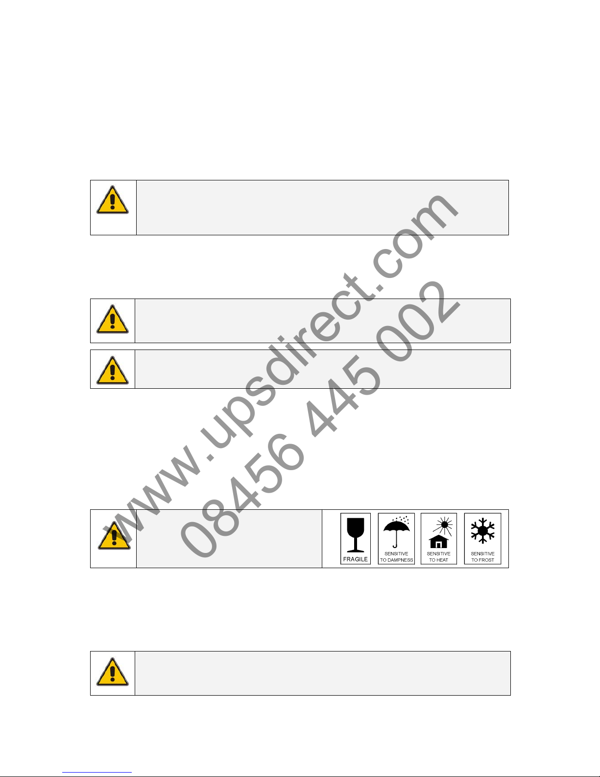
2.3 TRANSPORT / STORAGE
NOTE
Check for sufficient floor and elevation loading capacity. Move the UPS in its original package
to the final destination room. Do not stack other package on top.
BE CAREFUL!
Pay attention to the HEAVY WEIGHT of the UPS when downloading the UPS from the pallet!
Never try to lift the unit by yourself!
• No liability can be accepted for any transport damage when the equipment is shipped in non-original
packaging.
• Store the UPS in a dry location with the batteries in a fully charged state. Storage temperature must be
within -20 +45 °C. If the unit is stored for a period exceeding 3 months, optimal battery lifetime is obtained if
the storage temperature does not exceed 25°C.
• If the unit is stored for an extended period of time, the batteries must be recharged periodically. Connect
the unit to a wall outlet and recharge the batteries for 24 hours:
- if the storage temperature is within -20 and +30°C: every 3 months,
- if the storage temperature is within -20 and +45°C: every 1 month.
CAUTION
In case of storage, pay attention to:
2.4 WARRANTY
GE Consumer & Industrial SA, operating through its authorized agents, warrants that the standard products
will be free of defects in materials and workmanship for a period of 24 months after the date of invoice, or
such other period as may be specified.
NOTE
This warranty does not cover failures of the product which result from incorrect installation,
misuse, alterations by persons other than authorized agents, or abnormal operating conditions.
modifications reserved 5 User manual GT Series 6 - 10 kVA UPS 1.0 (GB)
www.upsdirect.com
08456 445 002
Page 6
3 INSTALLATION
3.1 PACKAGE CONTENTS
The UPS shipping box contains:
• 9 plastic parts
• 4 metal parts (rackmount installation see 3.3.1)
• 1 screws set – 1 display sticker (vertical orientation)
• 1 RS232 cable
• 1 CD-ROM (Software Tool)
• 1 parallel cable
• this manual
The Battery cabinet shipping box contains:
• 4 plastic parts
• 4 metal parts (rackmount installation see 3.3.1)
• 1 screws set
• 1 battery cable
• 1 display sticker (vertical orientation)
Inspect the UPS for damage after unpacking. If any damage is present please immediately notify the carrier
and place of purchase.
WARNING! In case of recognizable damage:
DO NOT connect any voltage to the unit
DO NOT put the unit into operation
3.2 INSTALLATION RULES
IMPORTANT
Before making any connection and switching on the GT Series UPS, please check the following
conditions:
• Your mains supply is 220 - 240 Volts and 50 Hz (if the mains frequency is 60Hz, the output frequency of the
UPS can be changed, see note in section 4.4.4), and
• The total power demand of the connected equipment does not exceed the rated output power of the GT
Series UPS (the rear panel of the UPS shows the model, chapter 9 the ratings).
• Avoid locations that are excessively humid, near water, near heat sources or in direct sunlight.
• The ambient temperature should not exceed 40°C. Optimal battery lifetime is obtained if the ambient
temperature does not exceed 30°C.
• It is important that ventilation air can move freely around and through the unit. Do not block the air vents.
• The branch circuit supply has to be protected as follows:
UPS model branch protection
GT Series 6kVA 25A slow
GT Series 10kVA 50A slow
CAUTION
To reduce risk of fire, connect the UPS only to a circuit provided with the fuse values
according to the above.
modifications reserved 6 User manual GT Series 6 - 10 kVA UPS 1.0 (GB)
www.upsdirect.com
08456 445 002
Page 7
3.3 INSTALLATION PROCEDURE
The UPS can be used in a stand alone tower format using the two supporting stands (section 3.3.2), or can
be mounted in a 19 inch rack using the two mounting brackets (section 3.3.1). All required items are
included in the delivery, except rails – available as railkit option.
NOTE
The UPS output sockets are live as soon as the UPS is connected to the mains, even if the UPS
has not been switched on via the front panel.
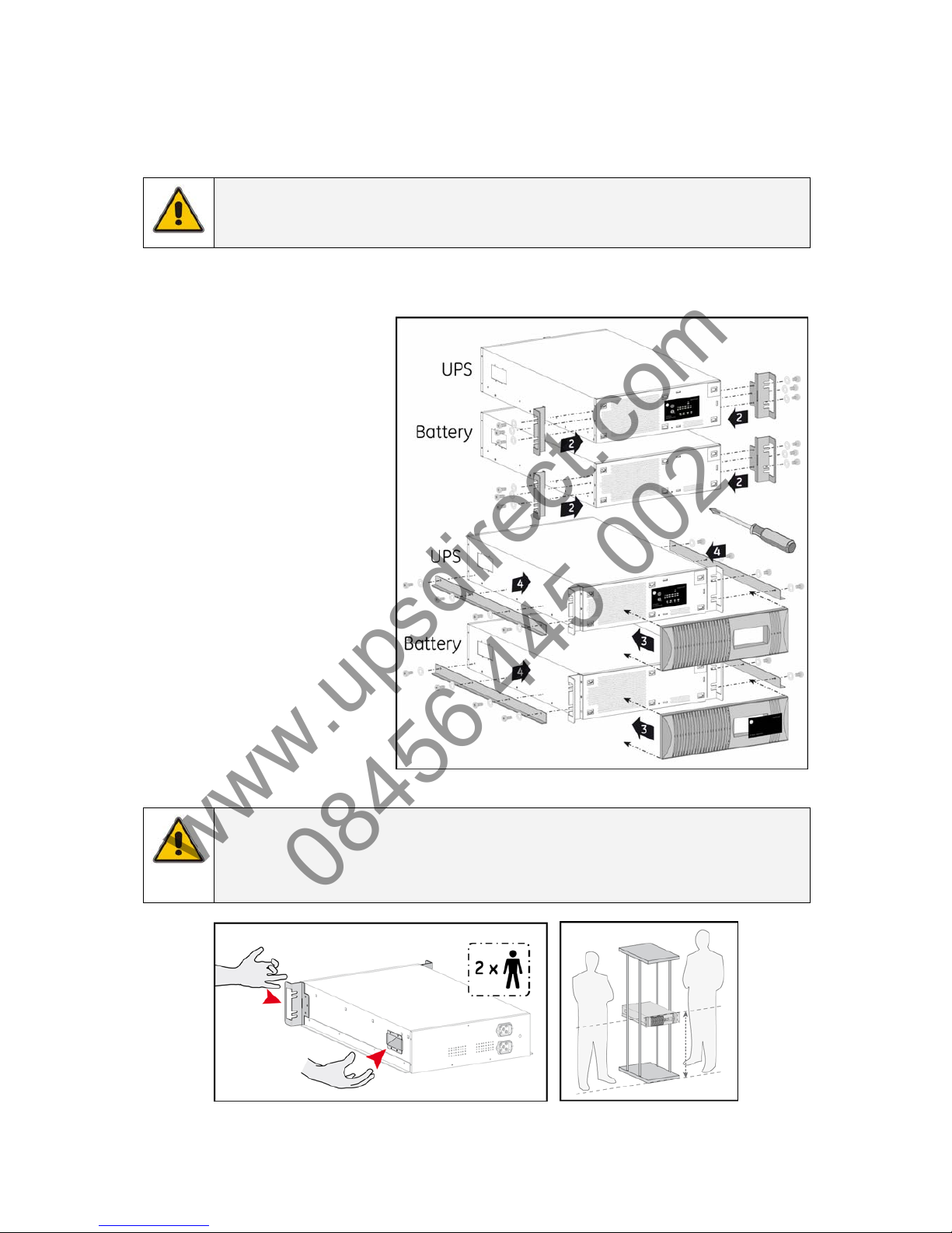
3.3.1 Rackmount installation – preparations
1. Place the UPS and matching
battery cabinet horizontally on
a flat surface.
2. Install the two mounting
brackets that came with the
unit using the provided screws
(2, fig. 3.3.1).
3. Mount the front panel by
pushing the plastic part into
the appropriate holes (3, fig.
3.3.1).
4. Install the UPS into a 19’ rack.
The UPS cabinet must be
supported by mounting rails,
do not mount it by using the
mounting brackets only. Fix
the mounting brackets on the
19 inch enclosure with screws.
fig. 3.3.1
NOTE
Please consider the weight of the UPS (see section 9) prior to installation to ensure the rack or
floor are capable of supporting the weight. For rack installation we recommend that the UPS
is placed in the lower section of the rack. Fit the unit and the battery into the rack cabinet with
the help of a second person.
The GT Series UPS is now ready for further connections. Please proceed with section 3.3.3.
modifications reserved 7 User manual GT Series 6 - 10 kVA UPS 1.0 (GB)
www.upsdirect.com
08456 445 002
Page 8
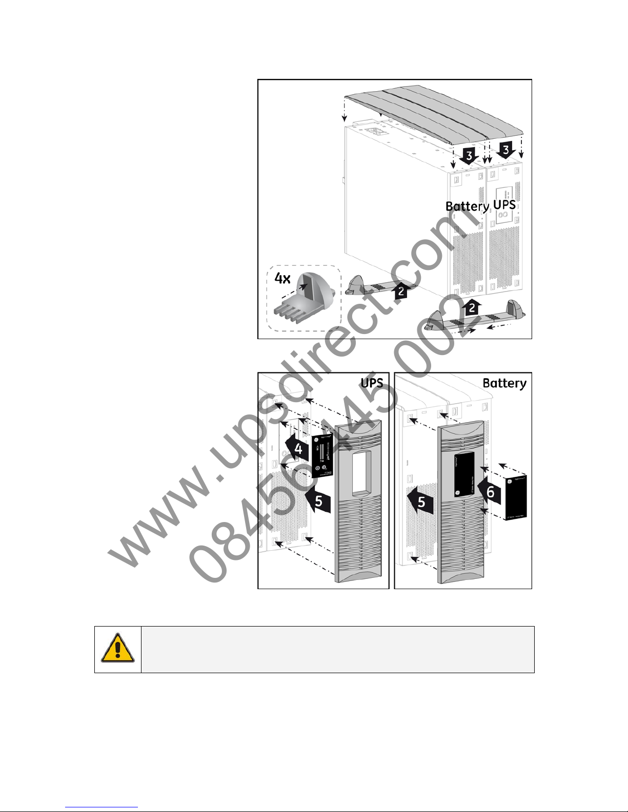
3.3.2 Vertical installation – preparations
1. Place the UPS and matching
battery cabinet horizontally on
a flat surface.
2. Assemble the plastic support
feet and mount them to UPS
and battery cabinet bottom
(2, fig. 3.3.2.a).
3. Place the cabinets upright
and mount the top cover
(3, fig. 3.3.2.a).
4. Attach the display sticker to the
UPS cabinet (4, fig. 3.3.2.b).
5. Mount the front panel on the
UPS and on battery cabinet
(5, fig. 3.3.2.b/c).
6. Attach the display sticker to the
battery cabinet (4, fig. 3.3.2.c).
The GT Series UPS is now ready for
further connection: proceed with
section 3.3.3.
fig. 3.3.2.a
fig. 3.3.2.b fig. 3.3.2.c
NOTE
There's no need to remove the front cover before applying the display sticker of the battery
cabinet.
modifications reserved 8 User manual GT Series 6 - 10 kVA UPS 1.0 (GB)
www.upsdirect.com
08456 445 002
Page 9

3.3.3 Connecting the battery
The battery pack connects to the UPS in the same way whether the UPS is being used in tower or
rackmount format. When used in tower format, the UPS and the battery pack can be mounted together in
one set of mounting supports (fig. 3.3.2.a)
Connect the battery cable provided between the UPS and the battery pack - plug it into the UPS battery
socket and the nearest battery connection socket on the battery pack (fig. 3.3.3.a).
NOTE
If additional battery packs are used, they connect via the previous battery pack. Thus, the cable
provided is attached via the nearest socket connection on the existing battery cabinet (fig. 3.3.3.b).
NOTE
When the UPS is connected to the mains, and the battery pack is connected to the UPS, the
batteries start charging. For best results, allow the UPS to recharge the batteries during a
period of approx. 8 hours. It is acceptable to use the UPS without first charging the battery,
but the runtime may be reduced.
fig. 3.3.3.a fig. 3.3.3.b
3.3.4 Connecting interface devices
The UPS is equipped with two interface ports: a DB9 communication port and an SNMP card slot.
The DB9 port can be connected to a computer system by connecting the serial cable included in the UPS
shipping box (fig.3.3.4.a). See section 5.1 for more information.
The SNMP slot allows easy installation of plug-in SNMP Card (fig.3.3.4.b). See section 5.2 for more
information.
fig. 3.3.4.a fig. 3.3.4.b
modifications reserved 9 User manual GT Series 6 - 10 kVA UPS 1.0 (GB)
www.upsdirect.com
08456 445 002
Page 10

3.3.5 Rear panel
1. Paralleling terminals (see
section 3.4.2)
2. ESD (emergency shutdown)
(see 4.4.10)
3. Input/output terminals (see
section 3.3.6)
4. External battery connector
5. Parallel port
6. DB9 communication port
7. RPO contacts (see 4.4.11)
8. SNMP card slot
9. Fan
10. Input circuit breaker:
2 pole, 30A/250Vac – 6kVA
2 pole, 63A/250Vac – 10kVA
11. Output sockets, IEC320 16A
12. Output circuit breakers
fig. 3.3.5.a
fig. 3.3.5.b
modifications reserved 10 User manual GT Series 6 - 10 kVA UPS 1.0 (GB)
www.upsdirect.com
08456 445 002
Page 11

3.3.6 Standard installation procedure
NOTE
Ensure that the UPS is isolated prior to installation; no live input source may be connected
to the UPS during the installation procedure. Open all the input/output switches/breakers on
the power distribution and ensure no one is able to close them during this installation step.
1. Remove the terminal cover (fig. 3.3.6.a).
2. Punch out the appropriate holes in the
terminal cover. Secure the input/output
cables using glands, according to
fig. 3.3.6.b.
3. Input. Connect the mains supply wires to
the terminals “L” (Line) and “N” (Neutral) and
the ground wire to terminal “
”. Ground
connection is essential! (fig. 3.3.6.c).
4. Output. Connect the load wires to the
terminals “L” (Line) and “N” (Neutral) and
the ground wire to terminal “
”. Ground
connection is essential! (fig. 3.3.6.c).
5. Re-install the terminal cover (fig. 3.3.6.d).
6. Ensure the battery cable is connected
between the battery cabinet and the
power unit. (see 3.3.3).
7. Connect the utility power to the UPS.
8. For a quick start proceed with section
4.2.1.
If parallel-operating units will be installed, please
proceed with section 3.4. Otherwise, proceed with
section 4.
fig. 3.3.6.a
fig. 3.3.6.b
fig. 3.3.6.c
fig. 3.3.6.d
NOTE
The UPS output sockets are live soon as the UPS is connected to the mains, even if the UPS
has not been switched on via the front panel.
modifications reserved 11 User manual GT Series 6 - 10 kVA UPS 1.0 (GB)
www.upsdirect.com
08456 445 002
Page 12

3.4 PARALLEL OPERATION
The paralleling cable delivered with each UPS allows you to connect up to 3 UPS together in a parallel
system.
NOTE
The units connected in parallel must be the same power rating.
(i.e. 6 kVA-6kVA not 6kVA-10kVA).
3.4.1 Installation of a parallel system
1. All inputs of the UPS must be supplied from the same phase. This is to enable bypass operation of the
parallel system. All inputs must be individually protected by fuses in the installation. The values of these
fuses should correspond to the values mentioned in section 3.2.
2. All outputs must be connected together, supplying the load. It is advised to install switches (S 1,2,3 fig 3.4)
in the output wiring, in order to be able to isolate a unit from the remaining system for service and
maintenance purposes.
3. The diameter of input and output cables must be according to the table in the installation
specifications (see chapter 9, table 1). Cables with different diameters can cause tripping fuses in the
UPS and/or the installation.
4. The length of all input cables from the input junction (Li, fig. 3.4) to the UPS inputs should be equal. The
same applies to the cables from the outputs to the output junction (Lo, fig. 3.4). The minimum length of
the input as well as the output cables is 3 meters.
5. The overall system load may not exceed 100% load of a single UPS in the configuration without the
addition of an external maintenance bypass.
fig. 3.4
modifications reserved 12 User manual GT Series 6 - 10 kVA UPS 1.0 (GB)
www.upsdirect.com
08456 445 002
Page 13

modifications reserved 13 User manual GT Series 6 - 10 kVA UPS 1.0 (GB)
3.4.2 Installing the parallel connection
NOTE
Ensure that the UPS is isolated prior to installation; no live input source may be connected
to the UPS during the installation procedure. Open all the input/output switches/breakers on
the power distribution and ensure no one is able to close them during this installation step.
1. Remove terminal cover (see 3.3.6).
2. Remove jumper S1 - S2 from parallel
connection terminals on the power unit
terminal block (fig. 3.4.2.a).
3. The parallel cable connection slot is at the
rear of the power unit. Remove terminal
cover (fig. 3.4.2.b).
4. Connect the cable provided with the UPS
(fig. 3.4.2.c).
5. One cable connects two UPS in parallel.
To connect a third UPS into the parallel
system, repeat the process as above (fig.
3.4.2.d).
6. Remount the cover with the additional
metal part included in the unit shipping
box (fig. 3.4.2.e/f).
7. For a quick start of the system proceed
with section 4.2.2.
fig. 3.4.2.a fig. 3.4.2.b
fig. 3.4.2.c
fig. 3.4.2.d
fig. 3.4.2.e fig. 3.4.2.f
www.upsdirect.com
08456 445 002
Page 14

4 OPERATION
4.1 OPERATING PANEL
fig. 4.1: operating panel
switch / LED main function
1
‘UPS off’ switch switches the UPS from normal operation to bypass and from
bypass or battery to standby.
2
‘UPS on’ switch switches on the UPS, starts quick battery test (see section 4.5),
mutes the buzzer.
3
LED ‘mains available’ (green) indicates availability of power mains.
4
LED ‘battery’ (yellow) on in case of battery operation: the mains power fails, and the
internal batteries supply the required power until either they are
depleted or mains power returns.
5
LED ‘operation’ (green) on when the output is supplied by the UPS (inverter).
6
LED ‘bypass’ (yellow) on when the UPS operates in bypass mode: the incoming mains
power is channeled directly to the load. Blinks if the input voltage
is out of bypass tolerance (see section 4.4.4 for more details).
7
LED ‘alarm’ (red) on in case of alarm.
8
LED bar ‘runtime capacity’ the remaining available battery runtime for the actual load, in % of
the maximum runtime with the actual load. When the alarm LED
is on, this bar may show a combination of LEDs, describing the
Alarm cause (see 4.4).
1º LED: 0-20% green
2º LED: 21-40% green
3º LED: 41-60% green
4º LED: 61-80% green
5º LED: 81-100% green
9
LED bar ‘load’ indicates to what extent the output capacity of the UPS is used
by the actual load. If e.g. the 25% and 50% LED are on, the load
exceeds 26% of the maximum load. If all 5 LEDs are on the unit
operates in overload. As this is an abnormal situation the alarm
LED will be on as well.
1º LED: 0-20% green
2º LED: 26-50% green
3º LED: 51-75% green
4º LED: 76-100% green
5º LED: >100% yellow
modifications reserved 14 User manual GT Series 6 - 10 kVA UPS 1.0 (GB)
www.upsdirect.com
08456 445 002
Page 15

4.2 START-UP
4.2.1 Start-up of a single unit
1. Ensure all switches and breakers
upstream to the UPS are closed.
2. Switch input circuit breaker to position
“On” (fig. 4.2.1).
3. Wait 45 seconds to allow the output
voltage to stabilise.
4. Press keypad “I” for 1 second. Within
few seconds LED ‘operation’ will be
illuminated and LED ‘bypass’ will be
extinguished.
5. The unit is now in operation; equipment
connected to the UPS can now be
switched on.
Load % will be shown on LED bar ‘load’.
fig. 4.2.1
4.2.2 Start up of a parallel system
1. Ensure all switches and breakers upstream to all UPS in the system are closed.
2. Switch to position “On” the input circuit breaker on all UPS in sequence (fig. 4.2.1).
3. Wait 45 seconds to allow the output voltage to stabilise.
4. Press keypad “I” on each UPS for 1 second. Within few seconds LED ‘operation’ will be illuminated and
LED ‘bypass’ will be extinguished.
5. The parallel system is now in operation; equipment connected to the system can now be switched on.
The load will be shared between the UPS as shown on the LED bar ‘load’.
4.3 USE: NORMAL OPERATION
4.3.1 Normal operation conditions:
1. The mains supply is present or within the tolerance (see chapter 9).
2. The UPS is on.
3. The load does not exceed the capacity of the UPS and
4. The operating temperature is below alarm level.
4.3.2 Switching off
1. Be sure that the load has been shut
down in a controlled way.
2. Press keypad “O” (fig. 4.3.2.a) for 1
second to switch the unit to bypass.
3. Press one more time the keypad “O”
for 1 second to switch off the unit
(fig. 4.3.2.a).
fig. 4.3.2.a
If electrical isolation is required (e.g. for maintenance purposes) proceed with steps 4-7 below:
4. If applicable, open any output circuit
breaker/switch.
5. Turn the UPS input switch to position
“Off” (fig. 4.3.2.b).
6. Disconnect the battery cabinet cable at
the rear of the UPS to eliminate any DC
power supply.
7. Ensure all switches and breakers
upstream to the UPS are open.
All LEDs should be out on the front panel;
the UPS is shut down.
fig. 4.3.2.b
NOTE
The residual DC voltage in the unit will be eliminated within 5 minutes.
modifications reserved 15 User manual GT Series 6 - 10 kVA UPS 1.0 (GB)
www.upsdirect.com
08456 445 002
Page 16

4.4 USE: STATUS AND ALARM INDICATIONS
o status indications the operating mode
! low priority alarms abnormal operating situations
!! high priority alarms situations in which the actual output voltage of the UPS is no longer guaranteed;
immediate action should be taken
Indicators on front panel (fig 4.1)
Situation
o Stand-by (4.4.9)
1 - 5
o Normal operation (4.3.1)
1 - 5 0 - 4
! Overload warning (4.4.5)
1 - 5
5
- - - -
1 / 0.5 sec
!! Battery not connected (4.5)
- - - -
0 - 4
!! Replace battery (4.4.5)
1& 3 0 - 4
- - - -
1 / 60 sec
! Bypass out of limits (4.4.4)
- - - -
1 - 5 0 - 4
o On bypass (4.4.1)
1 - 5 0 - 4
- - - -
1/120 sec
o On battery (4.4.2)
1 - 5 0 - 4
!! Battery low (4.4.3)
1
- - - -
0 - 4
- - - -
1 / 5 sec
!! Fault on bypass
- - - -
0 - 5
- - - -
!! Fault stand-by
- - - -
Operating modes and corresponding indications, see 4.3.1 - 4.3.2 and 4.4.1 – 4.4.9.
- - - - : intermittent
⎯⎯ : continuous
0 – 5 : number of LEDs that can be on, depending on runtime capacity / load bar
mute buzzer : press push button ‘I’ briefly
modifications reserved 16 User manual GT Series 6 - 10 kVA UPS 1.0 (GB)
www.upsdirect.com
08456 445 002
Page 17

4.4.1 On bypass
The UPS is equipped with an automatic bypass switch. This switch automatically transfers the load to the
mains if the UPS is unable to deliver the demanded output power due to overload or overtemperature. If all 5
load LEDs are illuminated, bypass operation is caused by an overload. If only first load LED is illuminated,
bypass operation is caused by overtemperature (see 4.4.8 tab .1).
The UPS will switch back to normal operation when the overload has been removed or the temperature has
dropped below alarm level.
If a power failure occurs during bypass operation, the UPS will switch to battery if possible, otherwise
output power is lost.
4.4.2 On battery
In normal operation conditions, if a mains failure occurs, the UPS uses the energy stored in the batteries to
supply the load.
The runtime capacity LED bar will show the remaining time (see 4.1).
For further information about runtime refer to chapter 9, Battery runtime.
The UPS will shutdown:
• After the batteries have been discharged (automatic restart if enabled), or
• If keypad ‘UPS off’ is pressed (restart via front panel required), or
• If a ‘UPS shutdown’ command is given by the computer (via UPS monitoring software). Restart
depends on the setting of “auto-restart” function (see 4.4.13).
4.4.3 Battery low (end of runtime)
If during battery operation the buzzer starts beeping every 5 seconds and the first LED of the battery
charge bar starts blinking the batteries are nearly discharged: the remaining runtime is less than 2 minutes
(default setting, adjustable via the UPS monitoring software). Controlled shutdown of any computer
equipment is absolutely necessary when this alarm is raised.
If the UPS operates at 100% load, the shutdown procedure should be completed within 2 minutes after the
‘battery low’ alarm started. If only part of the output capacity of the UPS is used this period can be longer, with
aged batteries this period can be shorter.
When the batteries are fully discharged, the UPS is no longer able to supply the connected equipment and
eventually output power is lost.
4.4.4 Bypass out of limits
The mains voltage or mains frequency are outside bypass tolerance but inside UPS input tolerance (see
chapter 9). Bypass operation is inhibited: if for whatever reason the UPS is not able to deliver the required
output, output power is lost. If the input frequency is often out of tolerance – during which bypass operation
is inhibited and an alarm is generated – it may be useful to disable bypass function (via UPS monitoring
software) after which the unit operates as a UPS without automatic bypass switch.
NOTE
The unit can be used as frequency converter: the input frequency range is 47.5-63Hz, the
output frequency is selectable 50/60 Hz, via UPS monitoring software.
If the unit is used in this configuration, the bypass function is no longer available.
4.4.5 Overload
The demanded power exceeds the nominal capacity of the UPS. The “overload warning” alarm occurs when
the load exceeds 150% the UPS will immediately switch to bypass, assuming that the conditions for a transfer
to bypass are fulfilled.
If an overload condition between 110-150% persists, the UPS will also switch to bypass operation. In both
conditions the “overload” alarm (see 4.4.8 tab. 1) is generated.
During an overload the UPS may automatically switch off within a few minutes (load dependent) and output
power is lost:
• if a transfer to bypass is inhibited (see section 4.4.4), or
• if the bypass function has been disabled (see section 4.4.4), or
• if the UPS operates on battery (see section 4.4.2).
To avoid these problems, be absolutely certain that the power demand of the protected equipment is within
the limits of the UPS.
modifications reserved 17 User manual GT Series 6 - 10 kVA UPS 1.0 (GB)
www.upsdirect.com
08456 445 002
Page 18

4.4.6 Replace battery
Either the batteries are almost chemically worn out or the battery wiring, including the battery fuse, is faulty. If
the batteries are aged, they must be replaced as soon as possible to ensure full protection for your equipment
(see section 7.4.1). Perhaps the 'replace battery' alarm occurs after a test which you started immediately after
installation or after a power failure. In this case the alarm may be incorrect as the batteries have been (partly)
discharged during transport or storage or during the power failure. For this reason we advise to execute
battery test only ater 5 hours on line operation with no mains failures. This allows the UPS to recharge the
batteries.
4.4.7 Alarm priority
‘General alarm’ comprises a group of alarms; the buzzer behaviour indicates the priority of the generated
alarm.
ON: Battery not connected (see section 4.5)
1 / 0.5 secs.: Overload (see section 4.4.5)
1 / 4 secs.: General Alarm
1 / 60 secs.: Battery test failed (see section 4.5)
1 / 120 secs.: On bypass (see section 4.4.1)
4.4.8 Fault mode
The UPS may be in “fault mode” if the following failure occurred:
Indicators on Battery Charge Bar
Fault Situation
LED 1 LED 2 LED 3 LED 4 LED 5 Buzzer
!! Charger Overvoltage
- - - -
1 / 4 sec
!! Output Short Circuit
- - - -
1 / 4 sec
!! Negative Power
!! Overload
- - - -
1 / 0.5 sec
!! Overtemperature
- - - -
1 / 4 sec
= continuous - - - - = intermittent !! = high priority
In “fault mode”, the UPS is “forced” on bypass or stand-by. After having solved the cause of the fault
condition you have to press the ‘UPS off’ button for 0.5 seconds to switch the UPS to normal mode or restart
the unit.
4.4.9 Stand-by
In stand-by mode the UPS is turned off (output power is lost) and the batteries are being recharged.
To put the unit in this condition press for 1 second the ‘UPS off’ switch, the unit switches to bypass.
Press one more time ‘UPS off’ switch for 1 second. The unit is now in stand-by mode.
Most changes of UPS settings are only possible in bypass or stand-by mode.
modifications reserved 18 User manual GT Series 6 - 10 kVA UPS 1.0 (GB)
www.upsdirect.com
08456 445 002
Page 19

4.4.10 Emergency Shutdown (ESD)
For safety reasons, an external 'emergency off' device (switch or relay) can be connected to the ESD
terminals 1-2 (fig. 4.4.10).
fig. 4.4.10
4.4.11 Remote Power Off (RPO)
RPO may be created by replacing the link with a switch with the characteristics of a ‘power off’ button
(see fig. 4.4.11). Under normal conditions the switch has to be closed, when it opens the UPS will
transfer to stand-by mode and output power is lost.
It is not possible to restart the unit while the RPO switch is open.
After closing the RPO switch press 'UPS off' button 2 times within 4 seconds to be able to restart the unit.
fig.4.4.11
4.4.12 No load shutdown
If this function is enabled and the load is <5%, the UPS will in case of a mains failure switch off and output
power is lost.
“No load shutdown” is disabled as default.
4.4.13 Auto Restart
The function may be enabled or disabled via UPS monitoring software. Auto Restart function acts after the
UPS has been shut down during a mains failure due to discharged batteries, no-load shutdown or
shutdown commanded by remote control:
- if the function is set “enabled”, the UPS will automatically restart when the mains returns
- if the function is set “disabled”, a manual restart is required, either as explained in section 4.2.1 or via the
UPS monitoring software.
modifications reserved 19 User manual GT Series 6 - 10 kVA UPS 1.0 (GB)
www.upsdirect.com
08456 445 002
Page 20

modifications reserved 20 User manual GT Series 6 - 10 kVA UPS 1.0 (GB)
4.5 BATTERY MANAGEMENT
Maximum battery life and reliability are obtained by the following features:
• Battery connection test
At start-up and every minute the unit performs an automatic test to check that the battery cabling and
fuses are properly connected.
If the test detects a battery disconnection, the corresponding alarm will be generated (see section 4.4.7).
• Quick battery test
A quick battery test may be launched to check whether batteries are healthy. To start the test, press
‘UPS on’ button (see section 4.1) for 0.5 seconds when the unit is in “normal operation” conditions (see
section 4.3.1).
In case of failure the corresponding alarm will be generated (see section 4.4.6 / 4.4.7)
• Deep battery test
A deep battery test will update the runtime calculation and may be started via the UPS monitoring
software. The test will start only if the battery charge level is higher than 90% and the load must be at
least 20% of the nominal rating. The runtime calculation will be updated only if the test can run
uninterrupted till complete battery discharge.
NOTE
When executing a deep battery test the available runtime in case of mains failure may be
shorter than normal. Don’t execute this test if reduced battery runtime is not acceptable.
NOTE
It’s possible to reset the battery test, by pressing the ‘UPS off’ switch (see 4.1) for 0.5 sec.
The UPS will switch to bypass mode.
www.upsdirect.com
08456 445 002
Page 21

5 COMMUNICATION
5.1 DB9 COMMUNICATION PORT
The RS232 port is a plug-in interface port, which enables advanced communication between the UPS and
the computer via serial cable (fig. 5.1) and UPS monitoring software.
The interface port is already operative in stand-by mode (see section 4.4.9).
To change settings of the unit, we strongly recommend to be sure that the unit is in stand-by mode. Some
settings can only be changed if the UPS operates in bypass or stand-by mode.
NOTE
The change of some settings can cause the unit to switch from bypass to standby and
output power is lost.
For more information regarding possible settings, please refer to the “Help” manual of the UPS monitoring
software.
fig. 5.1
5.2 SNMP INTERFACE CARD (OPTION)
This card allows the data interface to be connected directly to an Ethernet network. The card is fitted into the
SNMP Card slot (8, fig. 3.3.5.a). For more information, please refer to the user manual that comes with the
interface card.
6 OPTION: EXTENDED RUNTIME
Extended runtime can be obtained by connecting a separate battery extension pack to the UPS. In this case
the UPS must be informed about the new total battery capacity to allow a reliable recalculation of the
available runtime (via UPS monitoring software). Depending of the charge condition of the new batteries the
new runtime calculations may temporarily be unreliable.
Additional batteries increase the recharging time for the unit; all other operational information is the same as
for standard models.
modifications reserved 21 User manual GT Series 6 - 10 kVA UPS 1.0 (GB)
www.upsdirect.com
08456 445 002
Page 22

7 MAINTENANCE
7.1 SAFETY
DANGER
When the UPS operates, all parts of the electronics are directly connected to the utility and
high voltages are present on all internal parts, including the battery. Even after disconnection
from the utility, all parts inside the UPS, including the battery, conduct dangerous voltages
(except the COM port output). For your safety, only authorized service personnel may remove
the cabinet cover.
Refer to section 4.3.2 for further details.
7.2 GENERAL
The GE Digital Energy GT Series UPS is virtually maintenance free: take care of proper environmental conditions
and keep air inlets/outlets free of dust. Please read 3.2.
NOTE
Apart from battery replacement refer maintenance and service work to qualified and skilled
personnel only.
Refer to section 1.2 for further details.
7.3 RECYCLING THE UPS AT THE END OF SERVICE LIFE
NOTE
This product has been designed to respect the environment, using materials and
components respecting eco-design rules. It does not contain CFCs (Carbon Fluorine Chloride)
of HCFCs (Halogen Carbon Fluorine Chloride).
The batteries contain lead, which is a harmful substance for the environment.
Proper disposal or recycling of the batteries is required. Refer to your local codes for disposal
requirements.
GE Consumer & Industrial, in compliance with environment protection recommends that the
UPS equipment, at the end of its service life, must be recycled conforming to the local
applicable regulations.
7.4 BATTERIES
The service life of the battery is from 3 to 6 years, depending on the operating temperature and on the number
of discharge cycles.
As a healthy battery is critical to the performance of the UPS, an automatic quick battery test is performed
regularly to ensure failsafe operation (see section 4.5). When the condition of the battery is critical, a 'replace
battery' alarm will be activated (see 4.4 and 4.4.6). Replace the batteries as soon as possible.
modifications reserved 22 User manual GT Series 6 - 10 kVA UPS 1.0 (GB)
www.upsdirect.com
08456 445 002
Page 23

7.4.1 Battery replacement
Please refer to figure 7.4.1. Battery cabinet is the same for both power ratings, 6000VA and 10000VA.
NOTE
During battery replacement the UPS will not be able to support the load if a mains failure occurs! It
is recommended to switch off the load before disconnecting the DC connector as in section 4.3.2.
1. Remove the battery cable
between battery cabinet(s)
and UPS.
2. Remove battery cables
between eventual further
battery cabinets.
3. Replace the battery pack.
fig. 7.4.1
NOTE
To avoid battery malfunction, all battery packs have to be replaced! It’s not possible to replace
only 1 pack. Avoid connections between new and old battery packs.
4. Connect battery cables between additional battery cabinets.
5. Connect battery cable between battery cabinet(s) and UPS.
6. Check that battery data is set correctly via UPS monitoring software.
7. The UPS is now ready to supply the load in case of mains failure.
General guidelines:
• When replacing the batteries, use all of them of only the same type and size.
• Never short the battery terminals. Shorting may cause the battery to burn.
When working with batteries remove watches, rings or other metal objects
and only use insulated tools.
• Avoid charging in a sealed container.
• Proper disposal of batteries is required: refer to your local codes for
disposal requirements.
• Never dispose batteries in fire: they may explode.
• Never disassemble or reassemble batteries; their contents (electrolyte)
may be extremely toxic. If exposed to electrolyte, wash immediately with
plenty of water, if eye contact occurs flush with water and contact a
physician.
Don’t throw batteries
away, treat them as
harmful waste
The following table shows runtimes with up to 3 Battery Packs. 1 Battery Pack is the normal configuration.
Number of battery packs
Unit Load
x1 (normal) x2 x3
10% 201 min 346 min 555 min
25% 60 min 150 min 238 min
50% 26 min 61 min 99 min
75% 16 min 38 min 63 min
GT 6kVA CE
100% 10 min 26 min 44 min
10% 110 min 255 min 349 min
25% 37 min 87 min 155 min
50% 15 min 37 min 62 min
75% 8 min 22 min 37 min
GT 10kVA CE
100% 5 min 15 min 26 min
modifications reserved 23 User manual GT Series 6 - 10 kVA UPS 1.0 (GB)
www.upsdirect.com
08456 445 002
Page 24

8 TROUBLESHOOTING
Whenever a malfunction occurs, first check external factors (e.g. connections, temperature, humidity or load)
to determine whether the problem is caused by the unit itself or by its environment. Subsequently check the
thermal circuit breaker: it may be tripped. If so: reset it (see fig. 3.3.5.a/b) and be sure that the UPS is not
overloaded.
The following chart is a simple troubleshooting checklist. If the suggested solution does not succeed, or if the
information is insufficient to solve the problem, please contact your dealer or consult
www.GEDigitalEnergy.com
PROBLEM POSSIBLE CAUSE SOLUTION
Mains switched off Switch on mains supply
No mains voltage present Carry out mains inspection,
consult qualified electician
No display
No alarm
(UPS switched off)
Input fuse blown or circuit
breaker tripped
Replace fuse or reset breaker
Mains indicator not illuminating,
acoustic alarm intermittent
No mains voltage present Read section 4.4.2 – UPS on
battery
Mains indicator not illuminating,
mains voltage present, acoustic
alarm intermittent
Input fuse blown or circuit
breaker tripped
Replace fuse or reset breaker
UPS failure Contact UPS dealer or go to
www.gedigitalenergy.com
UPS overtemperature Allow UPS to cool down
Alarm LED illuminated,
continuous acoustic alarm
Overload at UPS output Reduce UPS load
Battery extension fuse switch is in
‘Open’ position
Switch to ‘On’ position
Batteries are not fully charged Charge batteries for 8 hours and
reconfirm runtime
Batteries are defective Contact UPS dealer
Delivered runtime less than
specified
Charger is defective Contact UPS dealer
Last load bar LED is lit, acoustic
alarm intermittent
Overload at UPS output Reduce UPS load
Incorrect communication cable Check whether correct cable is
used
PC interface defective or being
accessed by another service
Check if no other software is
accessing the interface
No communication between UPS
and load
Interference on the data cable Rearrange cables
www.upsdirect.com
08456 445 002
Page 25

9 SPECIFICATIONS
Model : GT6000 GT10000
Ratings
Voltage Amperes (VA) with computer type load : 6000 10000
Watts (W) with resistive load : 4200 7000
Input thermal circuit breaker (A) : 30 63
Internal input fuse 250V, slow (A) : 30 30*2
Input converter
AC input voltage : Nominal: 230 V
AC input voltage range : 84 - 276 V (84-175V with load de-rating)
input >276 Vac: UPS switches to battery operation
Input current waveform : sine wave
Input current (A) at nominal input voltage : 20.6 34.6
Input power factor : > 0.97
Input frequency range : 40 - 70 Hz
Inrush current : 60A
Output converter
AC output voltage : 220 / 230 / 240 V (selectable)
AC output voltage tolerance : ± 2%
Output frequency : 50/60 Hz, auto selection
Output frequency range : nominal ± 5% with mains synchronizing
Output waveform : sine wave
Harmonic distortion : < 3% with linear load, < 8% with non-linear full load
Power factor : 0.7
Crest factor (peak to RMS current) : ≤3:1
Capacity appliance outlets : with 55A Terminal Block
Bypass
AC input voltage range : ± 10% of selected output voltage
Frequency tracking rate : 1Hz/s
Frequency tracking range : ± 5% of selected frequency
Typical transfer time, msec : 0.5
Overload capability : fully protected against overload and short circuits
Overload behaviour during battery operation : 125% during 1 minute
: 150% during 10 seconds
Overload behaviour during bypass operation : depends on rating of thermal circuit breaker
typical: 125% of TCB value for 200 seconds
200% of TCB value for 10 seconds
300% of TCB value for 4 seconds
Batteries (ratings given for 25ºC)
Nominal voltage (Vdc) : 240 240
Number / Ah batteries (in battery kit and battery ext. pack) : 20pcs / 8Ah 20pcs / 8Ah
Type : sealed lead acid, maintenance free
Service life : up to 5 years (depending on use)
Recharge current : 1.2 A
Battery recharge time
(batt. discharged at 100% load) : 5 hours for 90% capacity
Runtime in minutes
at typical load (75%) : 17 9
% VA/Watts
25% 1500/1050 : 66
50% 3000/2100 : 28
75% 4500/3150 : 17
100% 6000/4200 : 12
% VA/Watts :
25% 2500/1750 : 37
50% 5000/3500 : 15
75% 7500/5250 : 9
100% 10000/7000 : - 5
General
Weight UPS kg : 24.5
Dimensions UPS (h
xwxd) : 130x410x660mm
Weight battery pack kg : 67
Dimensions battery pack : 130x410x660mm
Enclosure / protection : steel-plastic / IP20
Environment
Safety : EN 62040-1
Electromagnetic compatibility : EN 62040-2 (2006)
Ambient temperature : 0 to +40ºC
Audible noise at 1 meter : < 55 dB(A), load and temperature dependent
Max. relative humidity : 90% (non-condensing)
Colour : Black - RAL 9005
modifications reserved 25 User manual GT Series 6 - 10 kVA UPS 1.0 (GB)
www.upsdirect.com
08456 445 002
 Loading...