

Page 1

GEAppliances.com
Safety Instructions ........................ 2–4
Operating Instructions
Controls ........................................................... 5–7
Cycle Options ............................................... 8, 9
Using the Dryer ..............................................10
Installation Instructions
Before You Begin ..................................11, 12
Connecting an
Electric Dryer ..........................................14–16
Exhausting the Dryer ........................ 17–23
Final Setup ........................................................24
Location of your Dryer ......................12, 13
Reversing the Door Swing ............. 25–27
Stacking the Washer
and Dryer ..................................................28–30
Troubleshooting Tips ............. 32–34
Consumer Support
Consumer Support ................ Back Cover
Warranty (Canada) .................................... 36
Warranty (U.S.) .............................................. 35
Owner’s Manual &
Installation Instructions
DCVH480EK
DCVH485EK
PCVH480EK
PCVH485EK
Sécheuses
Manuel d’utilisation
et d’installation
La section française commence à la page 37
Secadoras
Manual del propietario
e instalación
La sección en español empieza en la página 73
Dryers
SAVE THESE INSTRUCTIONS
Write the model and serial
numbers here:
Model # ______________
Serial # _______________
They are on the label on the front
of the dryer behind the door.
175D1807P634 49-90370-1 05-14 GE
Page 2
IMPORTANT SAFETY INFORMATION.
READ ALL INSTRUCTIONS BEFORE USING.
WARNING!
For your safety, the information in this manual must be followed to minimize the risk
of fire or explosion, electric shock, or to prevent property damage, personal injury,
or death.
Do not store or use gasoline or other
flammable vapors and liquids in the
vicinity of this or any other appliance.
PROPER INSTALLATION
This dryer must be properly installed and located in accordance with the Installation Instructions
before it is used. Installation Instructions are included in the back of this manual.
Properly ground dryer to conform with all
governing codes and ordinances. Follow details
in Installation Instructions.
Install or store where it will not be exposed to
temperatures below freezing or exposed to
Operating Instructions Safety InstructionsConsumer Support Troubleshooting Tips
water or weather, which could cause permanent
damage and invalidate the warranty.
Connect to a properly rated, protected and sized
power supply circuit to avoid electrical overload.
Remove all sharp packing items and dispose of
all shipping materials properly.
Installation and service must be
performed by a qualified installer
or service agency.
Exhaust/Ducting
1
Dryers MUST be exhausted to the outside to
prevent large amounts of moisture and lint from
being blown into the room.
2
Use only rigid metal 4” diameter ductwork inside
the dryer cabinet. Use only rigid metal or flexible
metal 4-in diameter ductwork for exhausting to
the outdoors. Never use plastic or other
combustible, easy-to-puncture ductwork.
For complete details, follow the Installation
Instructions.
2
Page 3
GEAppliances.com
WARNING!
YOUR LAUNDRY AREA
Keep the area underneath and around your
appliances free of combustible materials,
(lint, paper, rags, etc.), gasoline, chemicals
and other flammable vapors and liquids.
Keep the floor around your appliances clean
and dry to reduce the possibility of slipping.
Close supervision is necessary if this appliance is
used by or near children. Do not allow children to
play on, with or inside this or any other appliance.
WHEN USING YOUR DRYER
Never reach into the dryer while the drum is
moving. Before loading, unloading or adding
clothes, wait until the drum has completely
stopped.
Keep the area around the exhaust opening
and adjacent surrounding areas free from the
accumulation of lint, dust and dirt.
Keep all laundry aids (such as detergents,
bleaches, etc.) out of the reach of children,
preferably in a locked cabinet. Observe all
warnings on container labels to avoid injury.
Never climb on or stand on the dryer top.
The laundry process can reduce the flame
retardancy of fabrics. To avoid such a result,
carefully follow the garment manufacturer’s
care instructions.
Clean the lint filter before each load to prevent lint
accumulation inside the dryer or in the room. DO
NOT OPERATE THE DRYER WITHOUT THE LINT
FILTER IN PLACE.
Do not wash or dry articles that have been
cleaned in, washed in, soaked in or spotted
with combustible or explosive substances (such as
wax, oil, paint, gasoline, degreasers, dry-cleaning
solvents, kerosene, etc.). These substances give
off vapors that may ignite or explode. Do not add
these substances to the wash water. Do not use
or place these substances around your washer
or dryer during operation.
Do not place items exposed to cooking oils in
your dryer. Items contaminated with cooking oils
may contribute to a chemical reaction that could
cause a clothes load to catch fire.
Any article on which you have used a cleaning
solvent or that contains flammable materials
(such as cleaning cloths, mops, towels used in
beauty salons, restaurants or barber shops, etc.)
must not be placed in or near the dryer until
solvents or flammable materials have been
removed. There are many highly flammable items
used in homes such as acetone, denatured alcohol,
gasoline, kerosene, some household cleaners,
some spot removers, turpentines, waxes, wax
removers and products containing petroleum
distillates.
Do not dry articles containing rubber, plastic
or similar materials such as padded bras, tennis
shoes, galoshes, bath mats, rugs, bibs, baby pants,
plastic bags or pillows that may melt or burn.
Some rubber materials, when heated, can under
certain circumstances produce fire by spontaneous
combustion.
Do not store plastic, paper or clothing that may
burn or melt on top of the dryer during operation.
Garments labeled Dry Away from Heat or Do Not
Tumble Dry (such as life jackets containing Kapok)
must not be put in your dryer.
Do not dry fiberglass articles in your dryer.
Skin irritation could result from the remaining
particles that may be picked up by clothing
during subsequent dryer uses.
To minimize the possibility of electric shock, unplug
this appliance from the power supply or disconnect
the dryer at the household distribution panel by
removing the fuse or switching off the circuit
breaker before attempting any maintenance or
cleaning (except the removal and cleaning of the
lint filter). NOTE: Pressing START/PAUSE or POWER
does NOT disconnect the appliance from the
power supply.
Consumer SupportTroubleshooting TipsOperating InstructionsSafety Instructions
3
Page 4
IMPORTANT SAFETY INFORMATION.
READ ALL INSTRUCTIONS BEFORE USING.
WARNING!
WHEN USING YOUR DRYER (cont.)
Never attempt to operate this appliance if it is
damaged, malfunctioning, partially disassembled,
or has missing or broken parts, including a
damaged cord or plug.
The interior of the machine and the exhaust duct
connection inside the dryer should be cleaned at
least once a year by a qualified technician. See
the Sorting and Loading Hints section on page 10.
You may wish to soften your laundered fabrics
or reduce the static electricity in them by using
a dryer-applied fabric softener or an antistatic
conditioner. We recommend you use either a
fabric softener in the wash cycle, according to
the manufacturer’s instructions for those products,
or try a dryer-added product for which the
manufacturer gives written assurance on the
package that their product can be safely used
in your dryer. Service or performance problems
caused by use of these products are the
responsibility of the manufacturers of those
products and are not covered under the
warranty of this appliance.
WHEN NOT USING YOUR DRYER
Grasp the plug firmly when disconnecting this
Operating Instructions Safety InstructionsConsumer Support Troubleshooting Tips
appliance to avoid damage to the cord while
pulling. Place the cord away from traffic areas
so it will not be stepped on, tripped over or
subjected to damage.
Do not attempt to repair or replace any part of
this appliance or attempt any servicing unless
specifically recommended in this Owner’s Manual
or in published user-repair instructions that you
understand and have the skills to carry out.
READ AND FOLLOW THIS SAFETY INFORMATION CAREFULLY.
SAVE THESE INSTRUCTIONS
Before discarding a dryer, or removing it from
service, remove the dryer door to prevent children
from hiding inside.
Do not tamper with controls.
4
Page 5
About the dryer control panel.
GEAppliances.com
WARNING! To reduce the risk of fire, electric shock, or injury to persons, read the IMPORTANT
SAFETY INSTRUCTIONS before operating this appliance.
Throughout this manual, features and appearance may vary from your model.
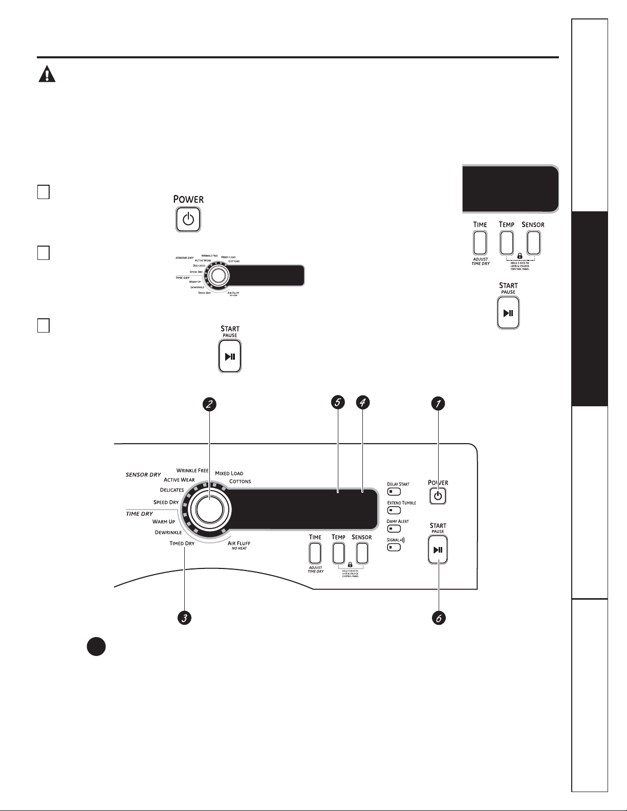
Quick Start
If the screen is dark, press the POWER button to “wake up”
the display.
1
Press the
2
Select a cycle by turning the
Cycle Knob.
3
If you selected a SENSOR DRYF\FOH³
just press the START/PAUSE button.
POWER
button.
If you selected a TIME DRY
F\FOH³VHOHFW\RXUKHDWVHWWLQJ
and the amount of time you
want your items to dry by
pressing the TIME button until
the desired time appears in
the display. Then press the START/
PAUSE button.
Power
1
Press to “wake up” the display. If the display is active, press to turn the dryer off.
NOTE: Pressing POWER does not disconnect the appliance from the power supply.
Consumer SupportTroubleshooting TipsOperating InstructionsSafety Instructions
5
Page 6
About the dryer control panel.
Dry Cycles
2
The dry cycle controls the cycle time for the drying process. The chart below will help you match
the dry setting with the loads.
Sensor Cycles
COTTONS For cottons and most linens.
MIXED LOAD For loads consisting of cottons and poly blends.
WRINKLE FREE For wrinkle-free/easy care and permanent press items.
ACTIVE WEAR Clothing worn for active sports exercise and some casual wear. Fabrics include new
technology finishes and stretch fibers such as spandex.
DELICATES For lingerie and special-care fabrics.
SPEED DRY For small loads that are needed in a hurry, such as sports or school uniforms. Can also be
used if the previous cycle left some items damp, such as collars or waistbands.
Time Dry Cycles
WARM UP Provides 10 minutes of warming time to warm up clothes.
DEWRINKLE For removing wrinkles from items that are dry or slightly damp. This cycle is not
recommended for delicate fabrics.
AIR FLUFF Use this feature to tumble items without heat.
Timed Dry
3
Operating Instructions Safety InstructionsConsumer Support Troubleshooting Tips
Use to set your own dry time. TIMED DRY is also recommended for small loads.
To use TIMED DRY:
1. Turn dry cycle dial to TIMED DRY.
2. Select the drying time by pressing the TIME button. You can increase the time in 10-minute
increments up to 1 hour and 20 minutes.
3. Select the DRY TEMP.
4. Close the door.
5. Press START/PAUSE.
Sensor Dry Level
4
The sensor continuously monitors the amount of moisture in the load. When the moisture in your
clothes reaches your selected dry level, the dryer will stop.
EXTRA DRY Use for heavy-duty fabrics or items that should be very dry, such as towels.
MORE DRY Use for heavy or mixed type of fabrics.
DRY Use for normal dryness level suitable for most loads. This is the preferred cycle
for energy saving.
LESS DRY Use for lighter fabric (ideal for ironing).
DAMP For leaving items partially damp.
NOTE: The Sensor Dry Levels can only be selected in a Sensory Dry Cycle.
6
Page 7
Dry Temp
5
You can change the temperature of your dry cycle.
ANTI-BACTERIAL This option may only be used with COTTONS or MIXED LOAD cycles. This option reduces
certain types of bacteria. The anti-bacterial process occurs when high heat is used
during a portion of this drying cycle.
NOTE: Do not use this cycle on delicate fabrics.
HIGH For regular to heavy cottons.
MEDIUM For synthetics, blends and items labeled permanent press.
LOW For delicates, synthetics and items labeled Tumble Dry Low.
EXTRA LOW For lingerie and special-care fabrics.
START/PAUSE
6
Press to start a dry cycle. If the dryer is running, press it once and it will pause the dryer.
Press it again to restart the dry cycle.
GEAppliances.com
“CLEAN LINT FILTER” (message)
This message stays on until the START button is pressed. This message is only a reminder.
Consumer SupportTroubleshooting TipsOperating InstructionsSafety Instructions
7
Page 8
About cycle options.
NOTE: Not all features are available on all dryer models.
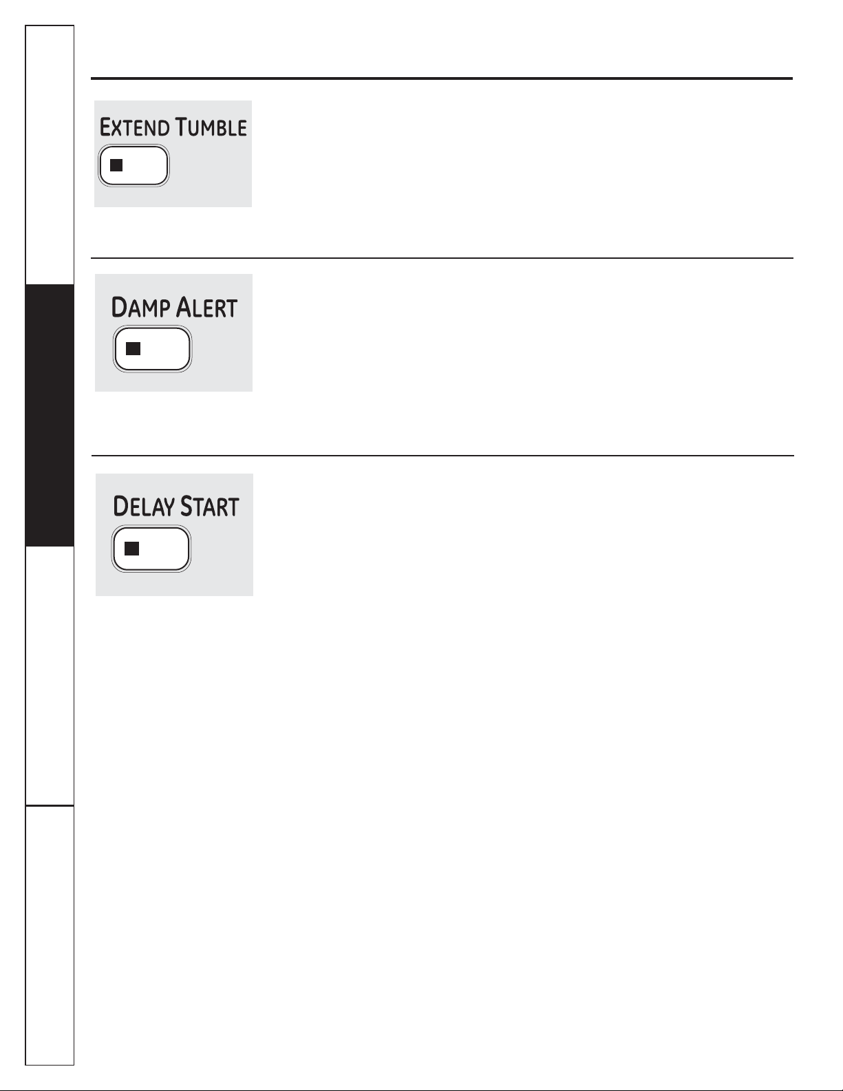
Extend Tumble
Operating Instructions Safety InstructionsConsumer Support Troubleshooting Tips
Minimizes wrinkles by adding
approximately 20 minutes of constant
no-heat tumbling followed by 70 minutes
of intermittent no-heat tumbling after
clothes are dry. The dryer is in EXTENDED
TUMBLE when the ESTIMATED CYCLE TIME
display is illuminated in a circular pattern.
Damp Alert
This option causes the dryer to beep when
clothes have dried to a damp level. Remove
items that you wish to hang dry. The
DAMP ALERT will only beep when this option
is selected (dry cycle keeps running).
Removing clothes and hanging them when
they are damp can reduce the need to iron
some items.
Delay Start
Use to delay the start of your dryer.
1. Choose your dry cycle and any options.
2. Press the DELAY START button. You
can change the delay time in 1-hour
increments (up to 18 hours) each time
you press the DELAY START button. Stop
pressing the button when your desired
time is displayed.
3. Press the START/PAUSE button to start
the countdown.
The countdown time will be shown in the
ESTIMATED TIME REMAINING display.
The light in the button will light up when
EXTEND TUMBLE is on.
NOTE: It is normal for the drum to pause
for short periods of time during EXTEND
TUMBLE.
The light in the button will light up when
DAMP ALERT is on.
NOTE: Only for DRY, MORE DRY and EXTRA
DRY sensor dry selections.
NOTES:
If the door is opened while the dryer is in
DELAY, the countdown time will continue
to count down the delay time. If the door
is not closed and the countdown time
expires, the cycle will not start until the
door is closed and the START/PAUSE
button is pressed.
You can delay the start of a dryer cycle
up to 18 hours.
The light in the button will light up when
DELAY START is on.
8
Page 9
GEAppliances.com
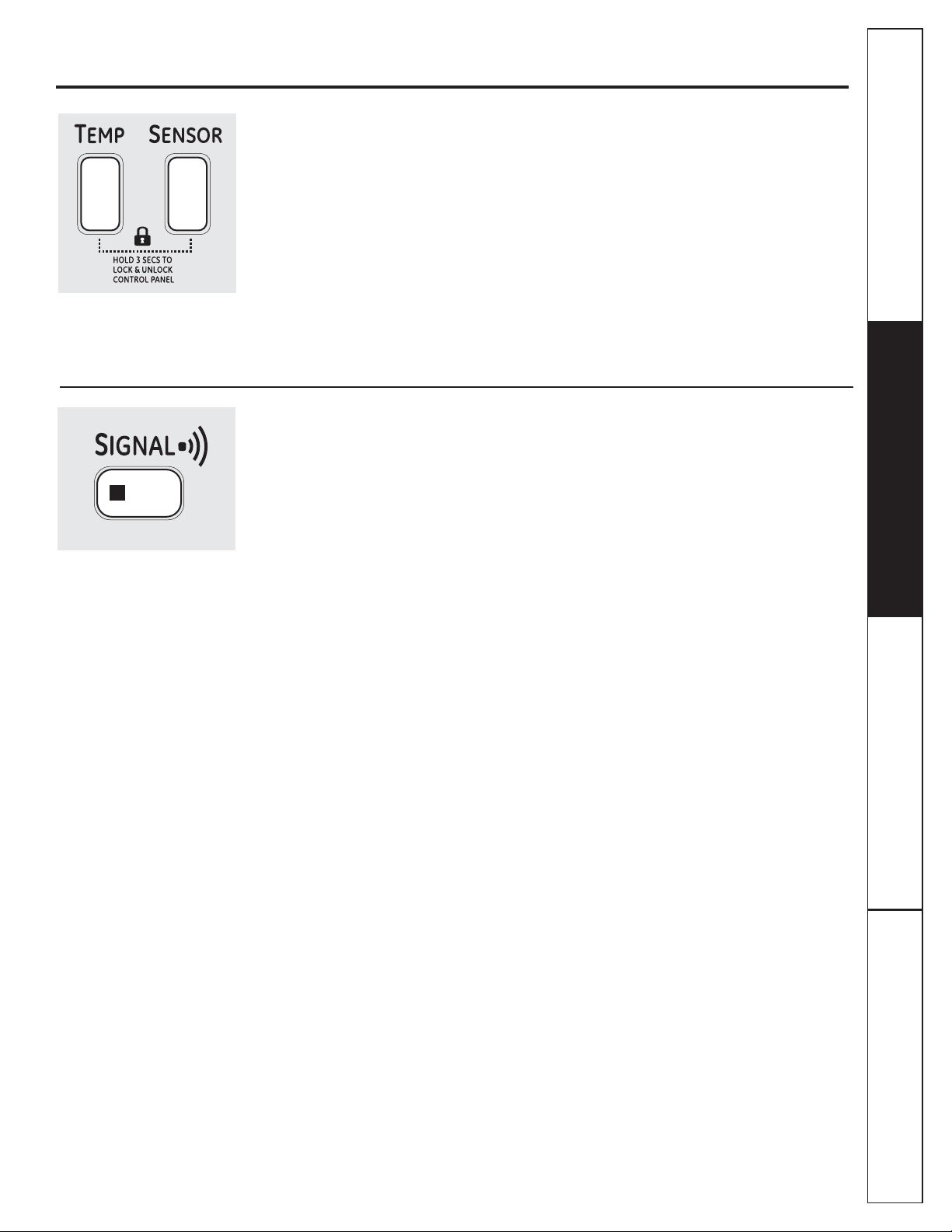
Lock
You can lock the controls to prevent any
selections from being made. Or you can
lock or unlock the controls after you have
started a cycle.
Children cannot accidentally start
the dryer by touching pads with
this option selected.
To lock the dryer, press and hold
the TEMP and SENSOR buttons together
for 3 seconds.
To unlock the dryer controls, press
and hold the TEMP and SENSOR buttons
together for 3 seconds. A sound will
indicate the lock/unlock status.
The control lock icon on the display will
light up when it is on.
NOTE: The POWER button can still be used
when the machine is locked.
Signal
When the light is “on,” the dryer will beep
at the end of the cycle and every time
you press a button on the control panel.
To turn the signal off, press the SIGNAL
button and the light will go off.
Consumer SupportTroubleshooting TipsOperating InstructionsSafety Instructions
9
Page 10
Using the dryer.
Always follow fabric manufacturer’s care label when laundering.
Operating Instructions Safety InstructionsConsumer Support Troubleshooting Tips
Sorting and Loading Hints
As a general rule, if clothes are sorted
properly for the washer, they are sorted
properly for the dryer. Try also to sort items
according to size. For example, do not dry
a sheet with socks or other small items.
Do not add fabric softener sheets once
the load has become warm. They may
cause fabric softener stains. Bounce®
Fabric Conditioner Dryer Sheets have
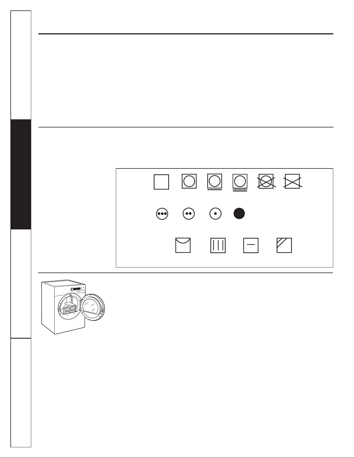
Fabric Care Labels
Below are fabric care label “symbols” that
affect the clothing you will be laundering.
Dry Labels
Tumble
dry
Dry
Normal
Permanent Press/
wrinkle resistant
Heat
setting
High
Medium
been approved for use in this dryer when
used in accordance with the manufacturer’s
instructions.
See below for lint filter cleaning instructions.
Do not overload. This wastes energy and
causes wrinkling.
Do not dry the following items: fiberglass
items, woolens, rubber-coated items, plastics,
items with plastic trim and foam-filled items.
Do not dry
(used with
do not wash)
Low
Gentle/
delicate
No heat/air
Do not tumble dry
10
Special
instructions
Line dry/
hang to dry
Drip dry
Care and Cleaning of the Dryer
Dryer Interior and Duct: The interior of
the appliance and exhaust duct should be
cleaned once a year by qualified service
personnel.
The Exterior: Wipe or dust any spills or
washing compounds with a damp cloth.
Dryer control panel and finishes may be
damaged by some laundry pretreatment
soil and stain remover products. Apply
these products away from the dryer. The
fabric may then be washed and dried
normally. Damage to your dryer caused
by these products is not covered by your
warranty.
Do not touch the surface or the display
with sharp objects.
The Lint Filter: Clean the lint filter before
each use. Remove by pulling straight up.
Open the filter and run your fingers across
the filter. A waxy buildup may form on the
lint filter from using dryer-added fabric
softener sheets. To remove this buildup,
wash the lint screen in warm, soapy
Dry flat
In the shade
water. Dry thoroughly and replace. Do not
operate the dryer without the lint filter
in place.
Vacuum the lint from the dryer lint
filter if you notice a change in dryer
performance.
Stainless Steel: To clean stainless steel
surfaces, use a damp cloth with a mild,
nonabrasive cleaner suitable for stainless
steel surfaces. Remove the cleaner
residue, and then dry with a clean cloth.
The stainless steel used to make
the dryer drum provides the highest
reliability available in a GE dryer. If
the dryer drum should be scratched or
dented during normal use, the drum
will not rust or corrode. These surface
blemishes will not affect the function
or durability of the drum.
The Exhaust Hood: Check with a mirror
that the inside flaps of the hood move
freely when operating. Make sure that
there is no wildlife (birds, insects, etc.)
nesting inside the duct or hood.
Page 11
Installation Dryer
Instructions
Questions? Call 800.GE.CARES (800.432.2737) or visit our Website at: GEAppliances.com
In Canada, call 1.800.561.3344 or visit www.GEAppliances.ca
DCVH480EK, DCVH485EK, PCVH480EK, PCVH485EK
If you are planning to stack the washer and dryer,
order Stacking Kit number GE24STACK to be used
for this dryer. Kit sold separately.
BEFORE YOU BEGIN
Read these instructions completely and carefully.
•
IMPORTANT – Save these instructions for local
electrical inspector’s use.
IMPORTANT – Observe all governing codes and
•
ordinances.
•
Install the clothes dryer according to the manufacturer’s
instructions and local codes.
•
Note to Installer – Be sure to leave these instructions
with the Consumer.
•
Note to Consumer – Keep these instructions for future
reference.
•
Clothes dryer installation must be performed by a
qualified installer.
•
This dryer must be exhausted to the outdoors.
•
Before the old dryer is removed from service or
discarded, remove the dryer door.
•
Service information and the wiring diagram are located
in the control console.
•
Do not allow children on or in the appliance. Close
supervision of children is necessary when the appliance
is used near children.
•
Proper installation is the responsibility of the installer.
•
Product failure due to improper installation is not
covered under the Warranty
• Install the dryer where the temperature is above 50°F
for satisfactory operation of the dryer control system.
• Remove and discard existing plastic or metal foil duct
and replace with UL-listed duct.
.
FOR YOUR SAFETY:
WARNING –
• To reduce the risk of severe injury or death, follow
all installation instructions.
• Clothes dryer installation must be performed by a
qualified installer.
• Install the clothes dryer according to these
instructions and in accordance with local codes.
• This dryer must be exhausted to the outdoors.
• Use only 4” rigid metal ducting for exhausting the
clothes dryer to the outdoors.
• DO NOT install a clothes dryer with flexible plastic
ducting materials. If flexible metal (semi-rigid or
foil-type) duct is installed, it must be UL-listed and
installed in accordance with the instructions found
in “Connecting the Dryer to House Vent” on page 18
of this manual. Flexible ducting materials are known
to collapse, be easily crushed and trap lint. These
conditions will obstruct dryer airflow and increase
the risk of fire.
• Do not install or store this appliance in any location
where it could be exposed to water and/or weather.
• The National Fuel Gas Code restricts installations of
gas appliances in garages. They must be 18 inches
off the ground and protected by a barrier from
vehicles.
• Save these instructions. (Installers: Be sure to leave
these instructions with the customer.)
Risk of Fire
11
Page 12
Installation Instructions
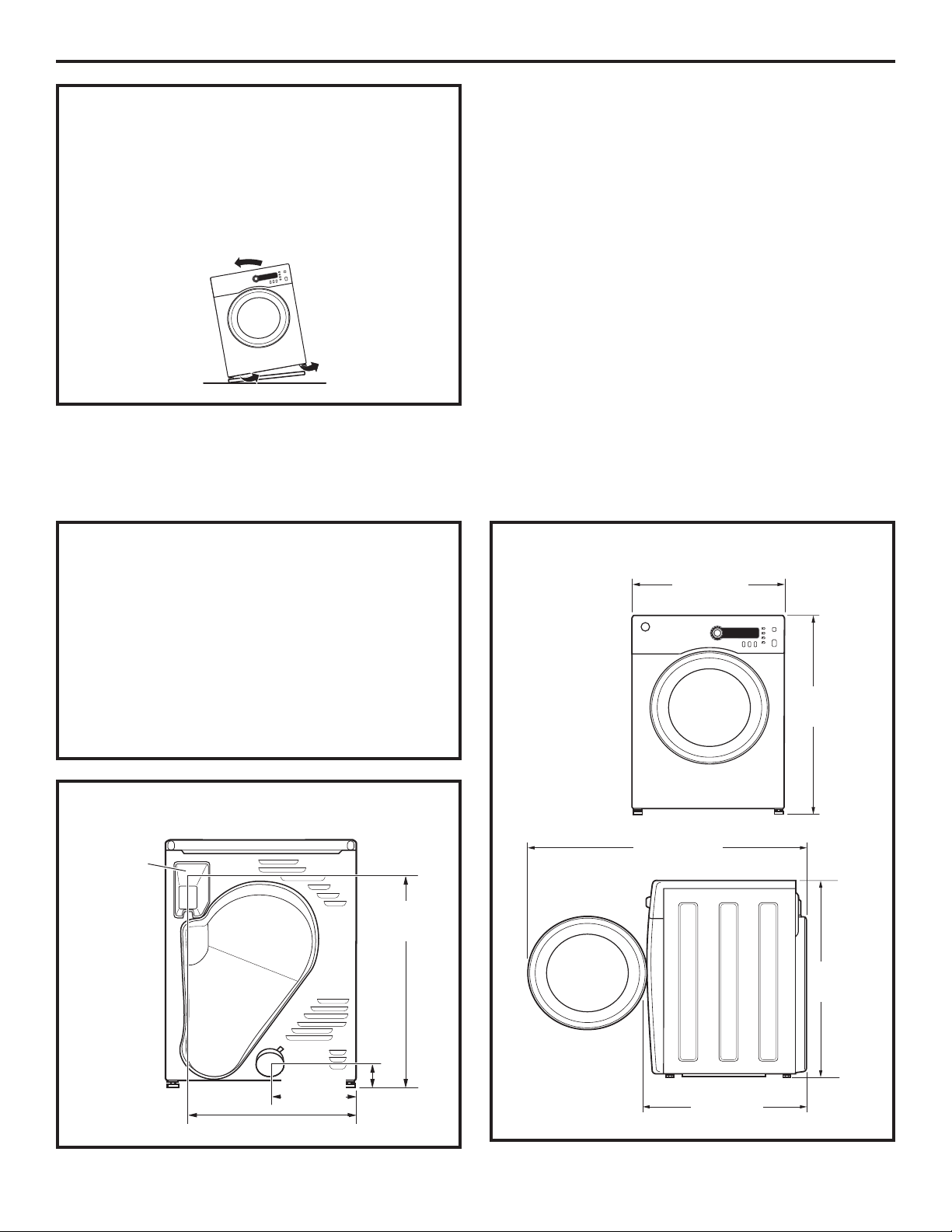
UNPACKING YOUR DRYER
Tilt the dryer sideways and remove the foam
shipping pads by pulling at the sides and breaking
them away from the dryer legs. Be sure to remove
all of the foam pieces around the legs.
Remove the bag containing the literature.
LOCATION OF YOUR DRYER
MINIMUM CLEARANCE OTHER THAN
ALCOVE OR CLOSET INSTALLATION
Minimum clearance to combustible surfaces and
for air openings are:
•
0 inch clearance both sides
•
3 inches front and rear
Consideration must be given to provide adequate
clearance for proper operation and service.
ELECTRICAL CONNECTION
Electrical
Connection
27.65”
Back View
(702 mm)
DRYER DIMENSIONS
23.5”
(598 mm)
Front View
33.4”
(848 mm)
42.9”
(1090 mm)
33.4”
(848 mm)
10.0”
(254 mm)
20.75” (527 mm)
4.0”
(101 mm)
Side View
25.7”
(653 mm)
12
Page 13
Installation Instructions
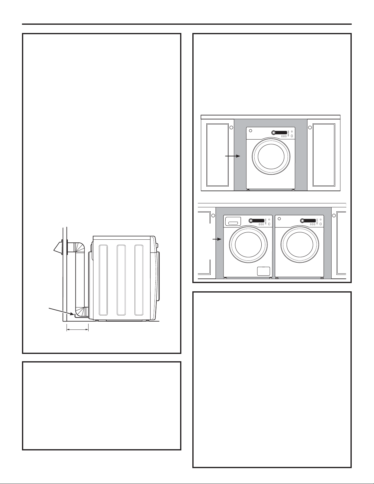
REQUIREMENTS FOR ALCOVE OR
CLOSET INSTALLATION
• Your dryer is approved for installation in
an alcove or closet, as stated on a label on
the dryer back.
The dryer MUST be vented to the outdoors. See
•
the EXHAUSTING THE DRYER section.
Minimum clearance between dryer cabinet and
•
adjacent walls or other surfaces is:
0” either side
3” front and rear
Minimum vertical space from floor to overhead
•
shelves, cabinets, ceilings, etc., is 52”.
Closet doors must be louvered or otherwise
•
ventilated and have at least 60 square inches
of open area equally distributed. If the closet
contains both a washer and a dryer, doors must
contain a minimum of 120 square inches of open
area equally distributed.
NOTE: WHEN THE EXHAUST DUCT IS LOCATED AT
THE REAR OF THE DRYER, MINIMUM CLEARANCE
FROM THE WALL IS 5.5 INCHES.
UNDERCOUNTER INSTALLATION
If an undercounter installation is desired:
•
No special dryer installation kit is required.
If the dryer is installed alone, a minimum of
•
60 square inches of open area is required.
If a washer and dryer are installed together,
a minimum of 120 square inches of open area
is required.
60
square
inches
min.
open
area
Dryer installed alone
Countertop and side cabinets
Washer and Dryer installed together
Countertop and side cabinets
Wire
frame
spacer
5.5”
(140 mm)
BATHROOM OR BEDROOM
INSTALLATION
• The dryer MUST be vented to the outdoors. See
EXHAUSTING THE DRYER.
The installation must conform with local codes or,
•
in the absence of local codes, with the NATIONAL
ELECTRICAL CODE, ANSI/NFPA NO. 70 (for electric
dryers) or NATIONAL FUEL GAS CODE, ANSI Z223
(for gas dryers).
120
square
inches
min.
open
area
MOBILE OR MANUFACTURED HOME
INSTALLATION
• The installation must conform to the
MANUFACTURED HOME CONSTRUCTION & SAFETY
STANDARD, TITLE 24, PART 32–80 or, when such
standard is not applicable, with AMERICAN
NATIONAL STANDARD FOR MOBILE HOME,
NO. 501B.
The dryer MUST be vented to the outdoors with
•
the termination securely fastened to the mobile
home structure. (See EXHAUSTING THE DRYER.)
The vent MUST NOT be terminated beneath a
•
mobile or manufactured home.
The vent duct material MUST BE METAL.
•
Do not use sheet metal screws or other
•
refastening devices which extend into the interior
of the exhaust vent.
Provide an opening with a free area of at least
•
25 sq. in. for introduction of outside air into the
dryer room.
13
Page 14
Installation Instructions
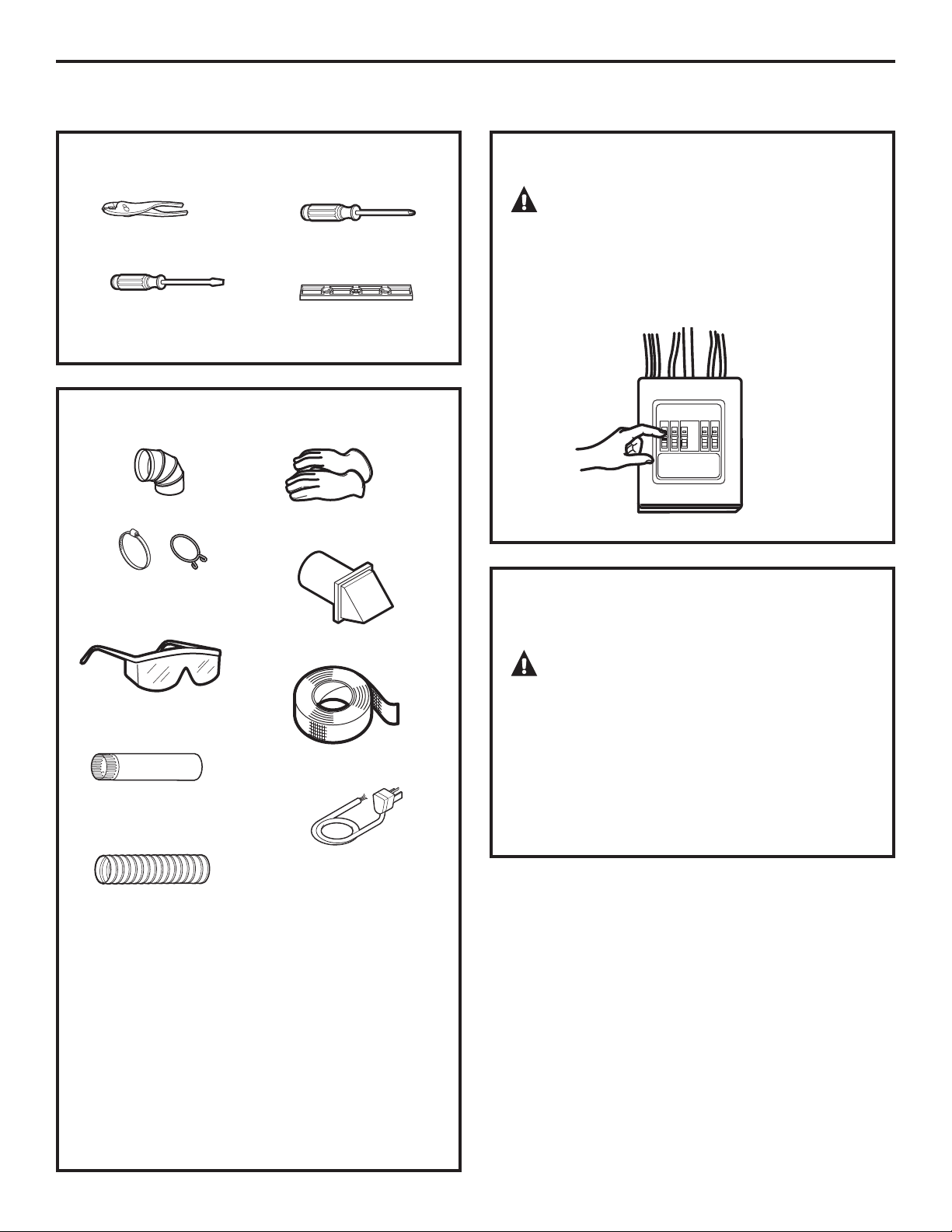
CONNECTING AN ELECTRIC DRYER
TOOLS YOU WILL NEED
Slip joint pliers
Flat-blade
screwdriver
Phillips screwdriver
Level
MATERIALS YOU WILL NEED
4” dia. metal elbow
4” duct clamps (2) or
4” spring clamps (2)
Gloves
FOR YOUR SAFETY:
WARNING
Before making the electrical connection, turn off
the circuit breaker(s) or remove the dryer’s circuit
fuse(s) at the electrical box. Be sure the dryer cord
is unplugged from the wall. NEVER LEAVE THE
ACCESS COVER OFF THE TERMINAL BLOCK.
ELECTRICAL CONNECTION
INFORMATION FOR ELECTRIC DRYERS
Safety glasses
4”-dia. metal duct
(recommended)
4”-dia., UL-listed
flexible metal duct (if
needed)
Exhaust hood
Duct tape
Dryer power cord kit
6 ft. long (not
provided with dryer)
UL-rated 120/240V,
30A with 3 or 4 prongs.
Identify the plug type as
per the house receptacle
before purchasing line
cord. (4-prong cord set
is included and installed
on Canadian models
PCVH480 and PCVH485.)
Stacking installations
may require a power
cord up to 6 feet in
length.
WARNING – To reduce the risk of
fire, electrical shock and personal injury:
•
Do not use an extension cord or an adapter
plug with this appliance.
The dryer must be electrically grounded in
•
accordance with local codes and ordinances
or, in the absence of local codes, in accordance
with the NATIONAL ELECTRICAL CODE,
ANSI/NFPA NO. 70.
14
Page 15
Installation Instructions
ELECTRICAL REQUIREMENTS
FOR ELECTRIC DRYERS
This dryer must be connected to an individual
branch circuit, protected by the required time-delay
fuses or circuit breakers. A three- or four-wire,
single-phase, 120/240V or 120/208V, 60Hz, 30-amp
circuit is required.
If the electric supply does not meet the above
specifications, then call a licensed electrician.
NOTE: For Canadian consumers with models
PCVH480 and PCVH485, cord set installation is not
required. Please skip to the next section, Exhausting
the Dryer.
GROUNDING INSTRUCTIONS
This dryer must be connected to a grounded
metal, permanent wiring system, or an equipmentgrounding conductor must be run with the circuit
conductors and connected to the equipmentgrounding terminal on the appliance.
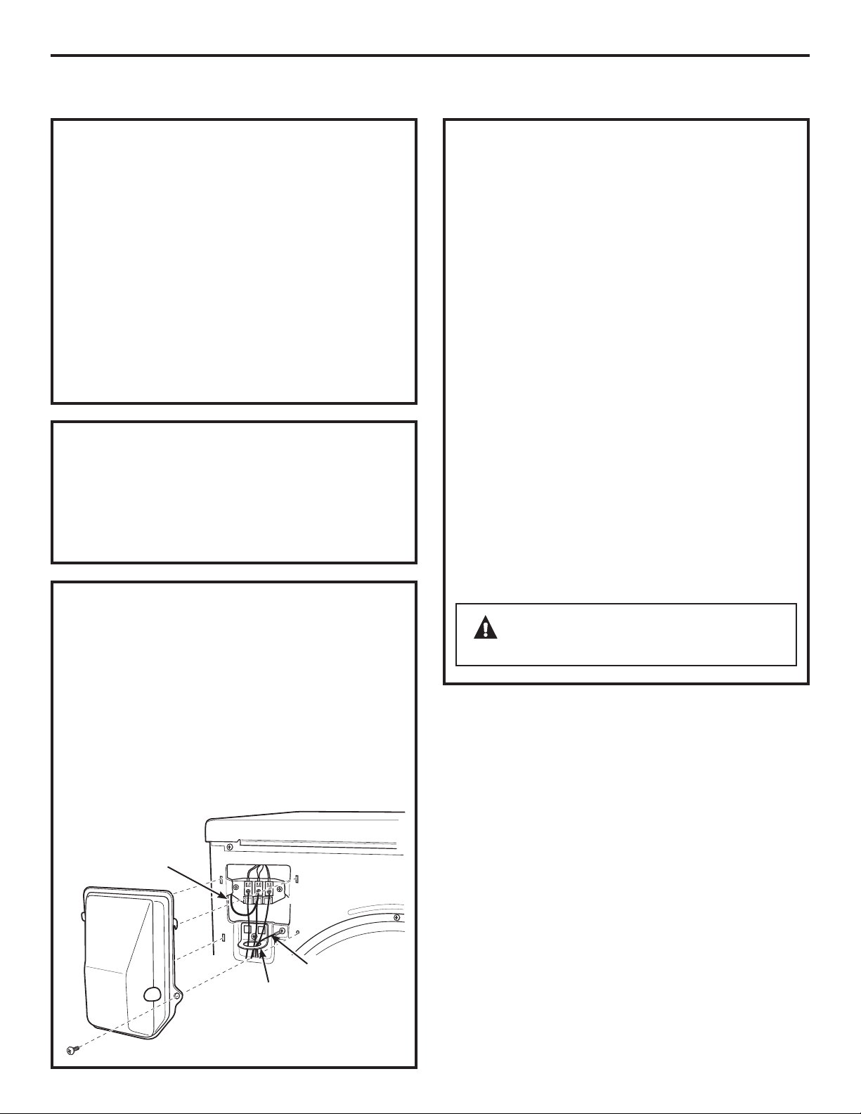
CONNECTING DRYER USING 4-WIRE
CONNECTION (MUST BE USED FOR
MOBILE HOME INSTALLATION) (cont.)
1. Turn off the circuit breaker(s) (30 amp) or remove
the dryer’s circuit fuse at the electrical box.
Be sure the dryer cord is unplugged from the wall
2.
receptacle.
Remove the power cord cover located at the
3.
upper back.
Remove the green ground screw and attach
4.
the ground strap to the center terminal along
with the (white) neutral line described below.
Keep the green ground screw for Step 7.
Bring the power cord through the bracket.
5.
Connect power cord as follows:
6.
A. Connect the 2 hot lines to the outer screws
of the terminal block (marked L1 and L2).
B. Connect the neutral (white) line to the center
of the terminal block (marked N).
Attach ground wire of power cord with the green
7.
ground screw (hole above strain relief bracket).
Tighten all terminal block screws (3) completely.
Reinstall the cover.
8.
CONNECTING DRYER USING 4-WIRE
CONNECTION (MUST BE USED FOR
MOBILE HOME INSTALLATION)
NOTE: Since January 1, 1996, the National
Electrical Code requires that new constructions
utilize a 4-wire connection to an electric dryer.
A 4-wire cord must also be used where local codes
do not permit grounding through the neutral.
3-wire connection is NOT for use on new
construction.
Ground strap
Green wire from
Bracket
power cord
WARNING – NEVER LEAVE THE
COVER OFF OF THE TERMINAL BLOCK.
15
Page 16
Installation Instructions
CONNECTING AN ELECTRIC DRYER (cont.)
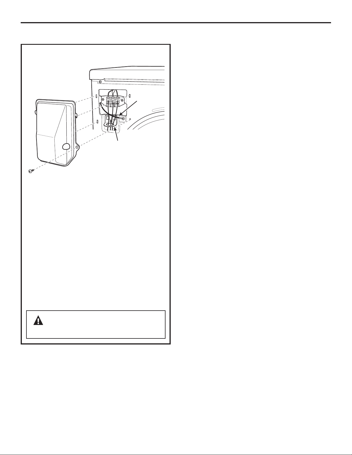
CONNECTING DRYER USING 3-WIRE
CONNECTION
Ground
strap
Bracket
1. Turn off the circuit breaker(s) (30 amp) or remove
the dryer’s circuit fuse at the electrical box.
Be sure the dryer cord is unplugged from the
2.
wall receptacle.
Remove the power cord cover located at the
3.
upper back.
Bring the power cord through the bracket.
4.
Connect power cord as follows:
5.
A. Connect the 2 hot lines to the outer screws
of the terminal block (marked L1 and L2).
B. Connect the neutral (white) line to the center
of the terminal block (marked N).
Be sure ground strap is connected to green
6.
ground screw on cabinet rear. Tighten all
terminal block screws (3) completely.
Reinstall the cover.
7.
WARNING – NEVER LEAVE THE
COVER OFF OF THE TERMINAL BLOCK.
16
Page 17
Installation Instructions
EXHAUSTING THE DRYER
WARNING – To reduce the
risk of fire or personal injury:
This clothes dryer must be exhausted to the outdoors.
•
”
• Use only 4
duct.
• Use only 4
(semi-rigid or foil-type) duct to connect the dryer
to the home exhaust duct. It must be installed in
accordance with the instructions found in “Connecting
the Dryer to House Vent” on page 18 of this manual.
• Do not terminate exhaust in a chimney, a wall, a
ceiling, gas vent, crawl space, attic, under an enclosed
floor, or in any other concealed space of a building.
• Never terminate the exhaust into a common duct with
a kitchen exhaust system. A combination of grease
and lint create a potential fire hazard.
• Do not use duct longer than specified in the exhaust
length table. Longer ducts can accumulate lint,
creating a potential fire hazard.
• Never install a screen in or over the exhaust duct. This
will cause lint to accumulate, creating a potential fire
hazard.
• Do not assemble ductwork with any fasteners that
extend into the duct. These fasteners can accumulate
lint, creating a potential fire hazard.
• Do not obstruct incoming or exhausted air.
• Provide an access for inspection and cleaning of the
exhaust system, especially at turns and joints. Exhaust
system shall be inspected and cleaned at least once
a year.
This dryer comes ready for rear exhausting. If space
•
is limited, use the instructions on pages 21–23 to
exhaust directly from the sides or bottom of the
cabinet.
rigid metal ducting for the home exhaust
”
rigid metal or UL-listed flexible metal
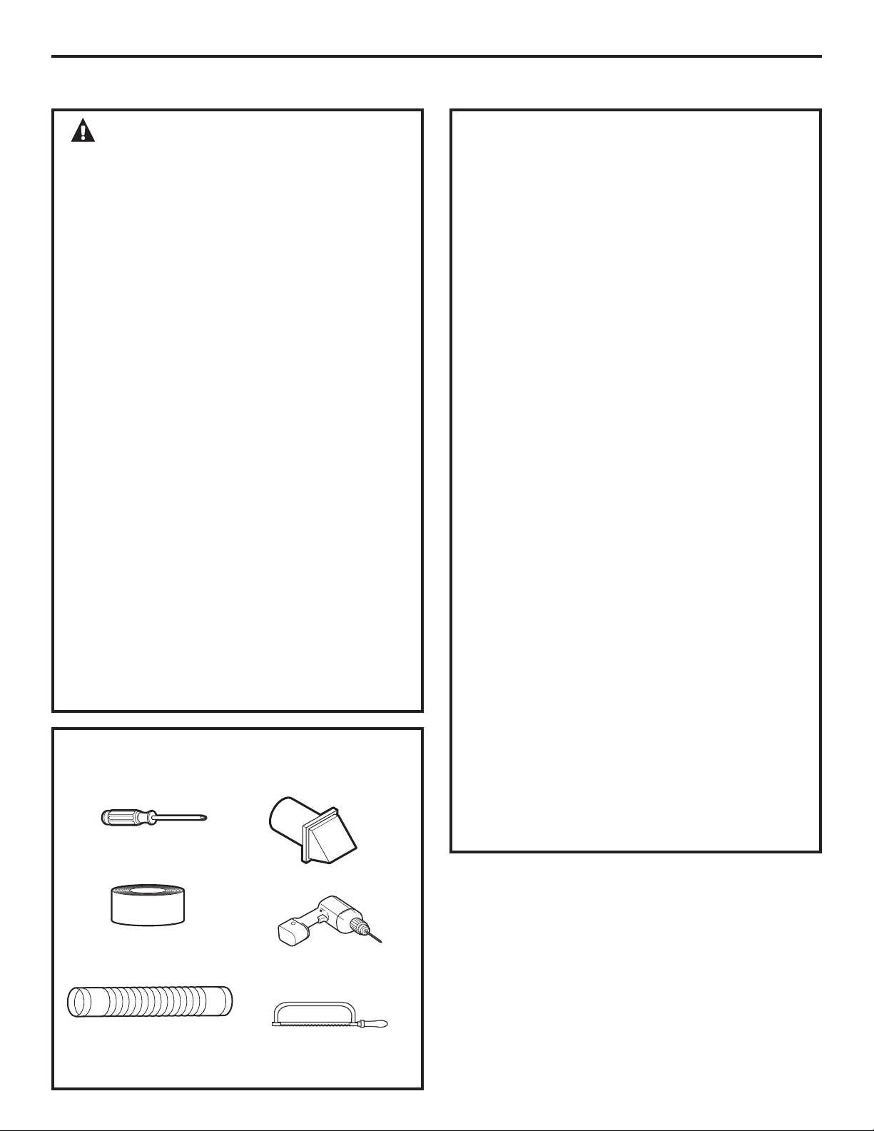
TOOLS AND MATERIALS YOU WILL
NEED TO INSTALL EXHAUST DUCT
Phillips-head
screwdriver
Vent hood
EXHAUST SYSTEM CHECKLIST
HOOD OR WALL CAP
•
Terminate in a manner to prevent back drafts
or entry of birds or other wildlife.
Termination should present minimal resistance
•
to the exhaust airflow and should require little
or no maintenance to prevent clogging.
Never install a screen in or over the exhaust
•
duct.
Wall caps must be installed at least 12” above
•
ground level or any other obstruction with the
opening pointed down.
SEPARATION OF TURNS
• For best performance, separate all turns by
at least 4 ft. of straight duct, including distance
between last turn and dampened wall cap.
For turns less than 4 ft. apart, see the Ducting
Component Equivalency Chart.
SEALING OF JOINTS
All joints should be tight to avoid leaks. The male
•
end of each section of duct must point away
from the dryer.
Do not assemble the ductwork with fasteners
•
that extend into the duct. They will serve as
a collection point for lint.
Duct joints should be made air- and
•
moisture-tight by wrapping the overlapped
joints with duct tape or aluminum tape.
Horizontal runs should slope down towards
•
outdoors 1/4” per foot.
INSULATION
•
Ductwork that runs through an unheated area
or is near air conditioning should be insulated
to reduce condensation and lint buildup.
Duct tape or duct
clamp
Rigid or UL-listed
flexible metal 4” (10.2
cm) duct
Drill with 1/8” drill bit
(for bottom venting)
Hacksaw
17
Page 18
Installation Instructions
EXHAUSTING THE DRYER (cont.)
CONNECTING THE DRYER TO
HOUSE VENT
RIGID METAL TRANSITION DUCT
For best drying performance, a rigid metal
•
transition duct is recommended.
Rigid metal transition ducts reduce the risk of
•
crushing and kinking.
UL-LISTED FLEXIBLE METAL (SEMI-RIGID)
TRANSITION DUCT
If rigid metal duct cannot be used, then UL-listed
•
flexible metal (semi-rigid) ducting can be used
(Kit WX08X10077).
Never install flexible metal duct in walls, ceilings,
•
floors or other enclosed spaces.
Total length of flexible metal duct should not
•
exceed 8 feet (2.4 m).
For many applications, installing elbows at both
•
the dryer and the wall is highly recommended (see
illustrations at right). Elbows allow the dryer to sit
close to the wall without kinking and/or crushing
the transition duct, maximizing drying performance.
Avoid resting the duct on sharp objects.
•
UL-LISTED FLEXIBLE METAL (FOIL-TYPE)
TRANSITION DUCT
In special installations, it may be necessary to
•
connect the dryer to the house vent using a flexible
metal (foil-type) duct. A UL-listed flexible metal
(foil-type) duct may be used ONLY in installations
where rigid metal or flexible metal (semi-rigid)
ducting cannot be used AND where a 4” diameter
can be maintained throughout the entire length
of the transition duct.
In Canada and the United States, only the flexible
•
metal (foil-type) ducts that comply with the “Outline
for Clothes Dryer Transition Duct, Subject 2158A”
shall be used.
Never install flexible metal duct in walls, ceilings,
•
floors or other enclosed spaces.
Total length of flexible metal duct should not
•
exceed 8 feet (2.4 m).
Avoid resting the duct on sharp objects.
•
For best drying performance:
•
1. Slide one end of the duct over the clothes
dryer outlet pipe.
2. Secure the duct with a clamp.
3. With the dryer in its permanent position,
extend the duct to its full length. Allow 2
duct to overlap the exhaust pipe. Cut off and
remove excess duct. Keep the duct as straight
as possible for maximum airflow.
4. Secure the duct to the exhaust pipe with the
other clamp.
”
of
FOR TRANSITION VENTING
(DRYER TO WALL), DO:
• DO cut duct
as short as
possible and
install straight
into wall.
DO use elbows
•
when turns are
necessary.
Elbows
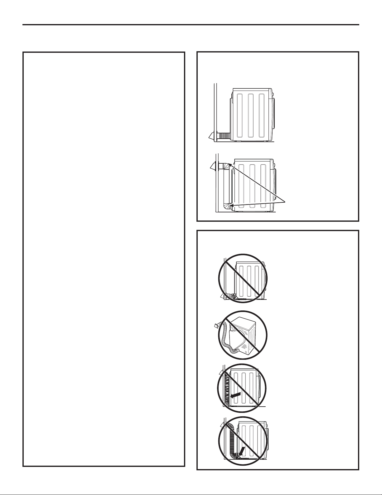
DO NOT:
• DO NOT bend or
collapse ducting.
Use elbows
if turns are
necessary.
DO NOT use
•
excessive
exhaust length.
Cut duct as short
as possible.
• DO NOT crush
duct against
the wall.
DO NOT set
•
dryer on duct.
18
Page 19
Installation Instructions
WARNING
USE ONLY METAL DUCT 4” DIAMETER (102 mm
FOR CANADA). DO NOT USE DUCT LONGER THAN
SPECIFIED IN THE EXHAUST LENGTH TABLE.
'U\HU([KDXVWLQJ,QIRUPDWLRQ³0HWDO'XFW2QO\
Ducting Materials: For best performance, this dryer
should be vented with 4” diameter all-rigid metal
exhaust duct.
Exhaust Length Calculation:
1. Determine the number of 90º turns needed for
your installation.
2. The maximum length of 4’ rigid (aluminum or
galvanized) duct which can be tolerated is shown
in the table.
A turn of 45º or less may be ignored. Two 45º
turns within the duct length should be treated
as a 90º elbow.
A turn over 45º should be treated as a 90º elbow.
Best Performance
Maximum Length
of a 4” Dia.
Rigid Metal Duct
CAUTION:
terminate exhaust into a chimney, under any
enclosed house floor (crawl space), or into an attic,
since the accumulated lint could create a fire hazard
or moisture could cause damage. Never terminate
the exhaust into a common duct or plenum with a
kitchen exhaust, since the combination of lint and
grease could create a fire hazard.
Exhaust ducts should be terminated in a dampered
wall cap to prevent back drafts, bird nesting, etc.
The wall cap must also be located at least 12” above
the ground or any other obstruction with
the opening pointed down.
Other terminations, such as louvered wall boxes,
are acceptable provided they are equivalent to
a 4” opening dampered wall cap.
For more information on venting kits and
accessories, please call 1.800.GE.CARES.
For personal safety, do not
Exhaust Hood Type
Number of A B
90º Turns 4” Opening 2-1/2” Opening
Front-Loading Dryers 0 90 ft. 60 ft.
1 60 ft. 45 ft.
2 45 ft. 35 ft.
3 35 ft. 25 ft.
4”
4”
2-1/2”
19
Page 20
Installation Instructions
EXHAUSTING THE DRYER (cont.)
BEFORE YOU BEGIN
• Remove and discard existing plastic or metal
duct and replace with UL-listed duct.
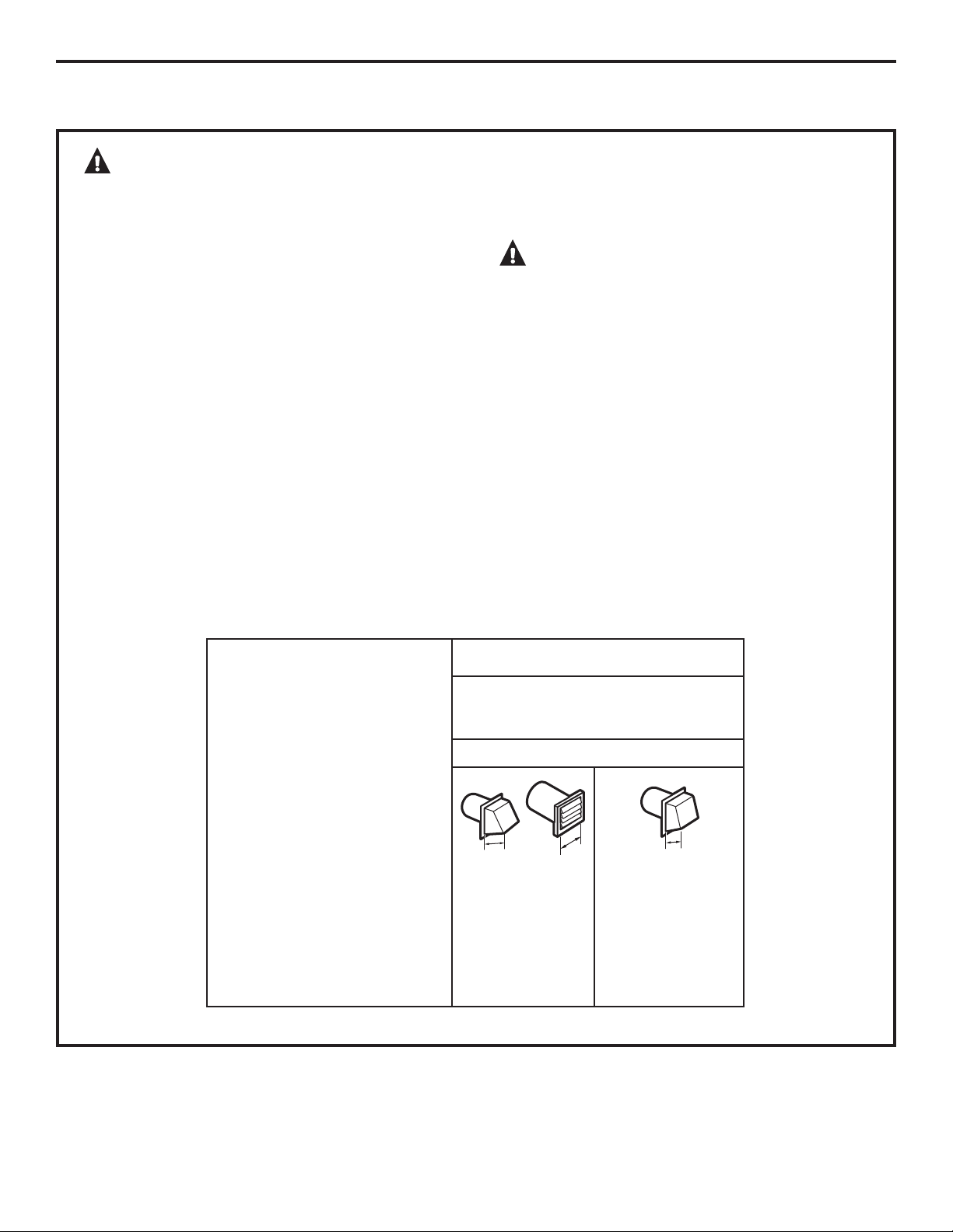
• Remove any lint from the wall exhaust opening.
Wall
Internal
duct
opening
Check that exhaust
hood damper
opens and closes
freely.
STANDARD REAR EXHAUST
We recommend that you install your dryer before
installing your washer. This will permit direct
access for easier exhaust connection.
Pull out the wire spacer and swing upward to its full
extension. Let the wire spacer lay flat and extended
on the floor. This will prevent the dryer from being
pushed too close to a wall or object, causing the
ducting to come loose from the dryer.
RECOMMENDED CONFIGURATION
TO MINIMIZE EXHAUST BLOCKAGE
Using duct elbows will prevent duct kinking and
collapsing.
Transition
ducting
Wire
frame
spacer
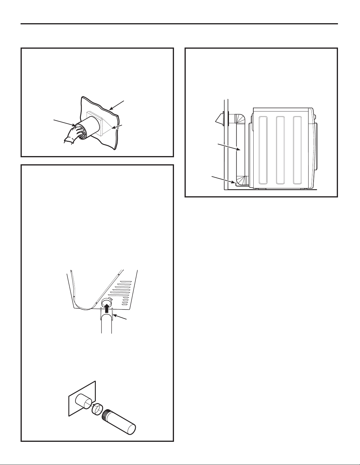
Slide the end of the exhaust duct on the back
of the dryer and secure with duct tape or a
hose clamp.
Wire frame
spacer
Duct
NOTE: We strongly recommend using rigid metal
exhaust duct.
•
For straight-line installation, connect the dryer
exhaust to the wall, using duct tape.
Wall side
Dryer
side
20
Page 21
Installation Instructions
SIDE VENTING:
Dryer Exhaust to side of cabinet
WARNING – BEFORE
PERFORMING THIS EXHAUST INSTALLATION, BE
SURE TO DISCONNECT THE DRYER FROM ITS
ELECTRICAL SUPPLY. PROTECT YOUR HANDS
AND ARMS FROM SHARP EDGES WHEN
WORKING INSIDE THE CABINET. BE SURE TO
WEAR GLOVES.
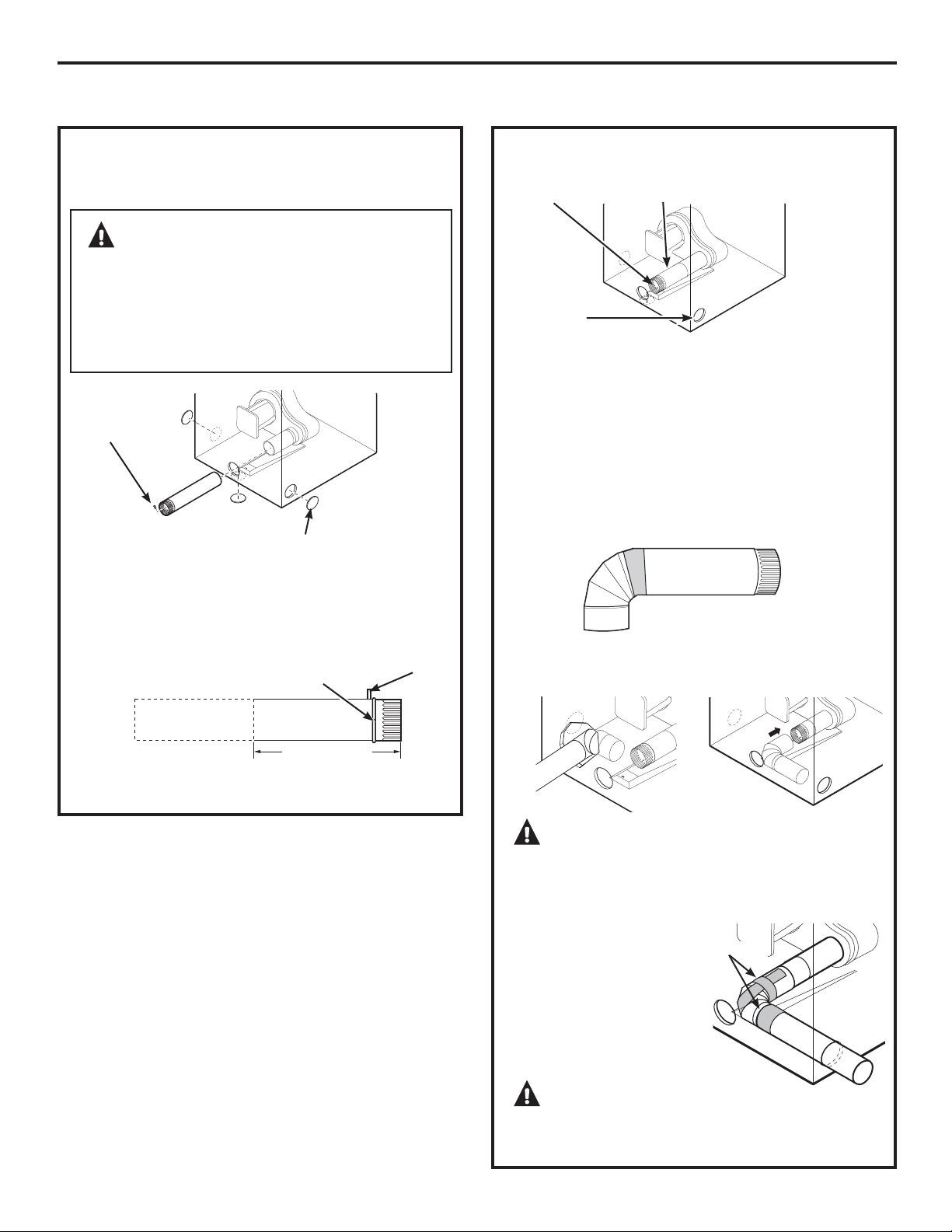
Remove
screw and
save
Detach and remove the bottom, right or left side
knockout as desired. Remove the screw from the
rear of the casing and save. Pull the duct out of
the dryer.
Right
Bottom
Remove desired
knockout (one only)
Fixing hole
Left
Tab
ADDING A NEW DUCT
Fixing hole
Left side
exhaust
Reconnect the cut portion (A) of the duct to the
blower housing. Make sure that the screw holes
in the duct and ramp base are aligned. Use the
screw saved previously to secure the duct in place
through the ramp on the appliance base.
Portion “A”
ADDING ELBOW AND DUCT FOR EXHAUST
TO LEFT OR RIGHT SIDE OF CABINET
• Tape the connection between the duct and elbow.
•
Insert the duct with elbow through the rear
opening and connect to the internal duct.
A
4.9” (125 mm)
Cut the duct as shown and keep portion A.
CAUTION: Be sure not to pull or
damage the electrical wires inside the dryer when
inserting the duct. A slight interference may
occur between the exhaust and the wire
components.
• Apply duct tape as
shown on the joint
between the dryer
internal duct and
the elbow, and also
the joint between the
elbow and the side duct.
Duct tape
CAUTION: Internal duct joints must be
secured with tape; otherwise, they may separate
and cause a safety hazard.
21
Page 22
Installation Instructions
EXHAUSTING THE DRYER (cont.)
SIDE VENTING (cont.)
ADDING COVER PLATE TO REAR OF CABINET
(SIDE EXHAUST)
Cover Plate
Connect standard metal elbows and ducts to
complete the exhaust system. Cover back opening
with a cover plate (Cover Plate – WE1M454)
available from your local service provider. Place
dryer in final location.
WARNING – NEVER LEAVE
THE BACK OPENING WITHOUT THE PLATE.
COVER BACK OPENING WITH A COVER PLATE
(COVER PLATE – WE1M454) AVAILABLE FROM
YOUR LOCAL SERVICE PROVIDER.
BOTTOM VENTING:
Dryer Exhaust to the bottom of cabinet
WARNING – BEFORE
PERFORMING THIS EXHAUST INSTALLATION, BE
SURE TO DISCONNECT THE DRYER FROM ITS
ELECTRICAL SUPPLY. PROTECT YOUR HANDS
AND ARMS FROM SHARP EDGES WHEN
WORKING INSIDE THE CABINET. BE SURE TO
WEAR GLOVES.
Remove
screw
and save
Bottom
Remove desired
knockout (one only)
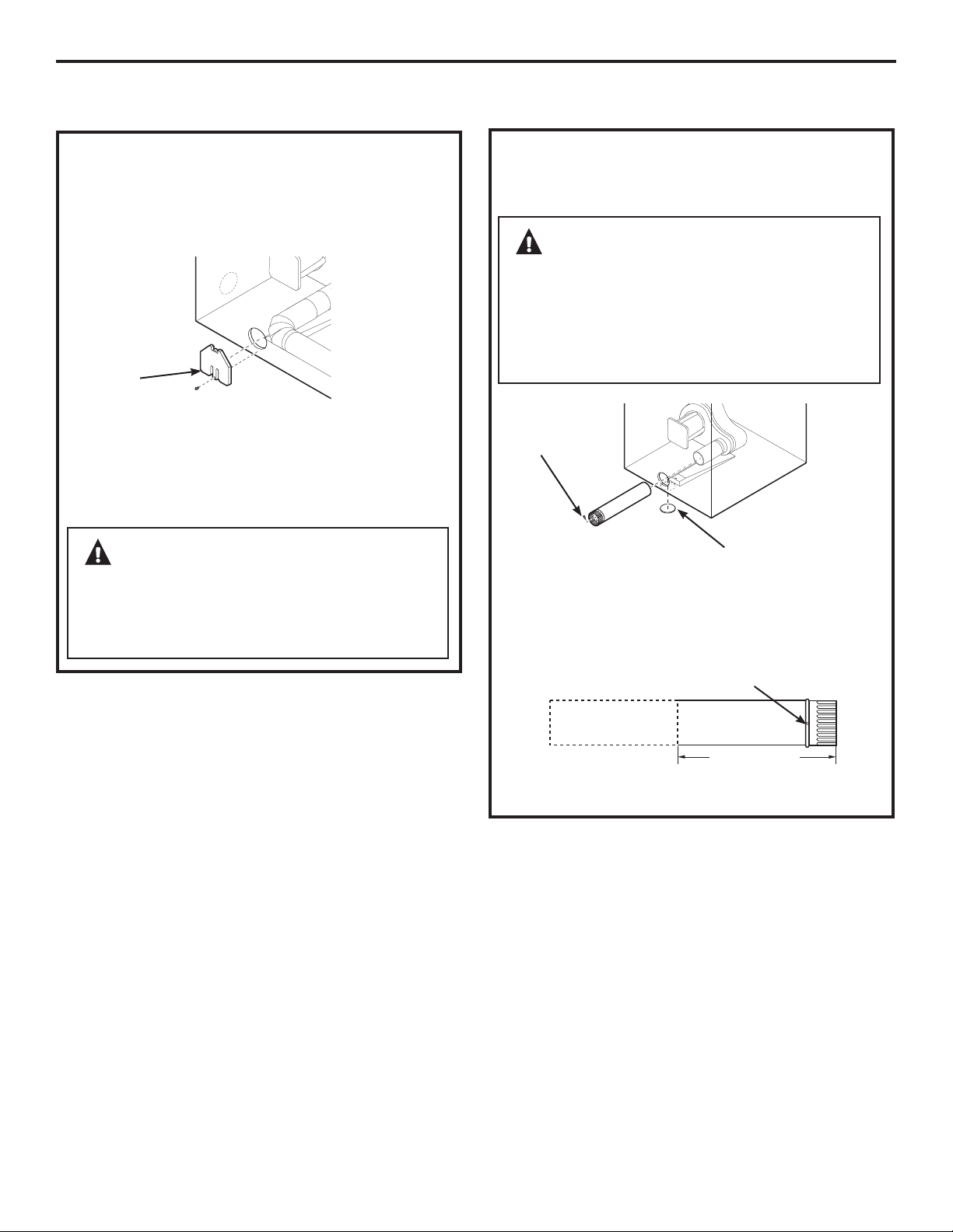
Remove the screw inside the dryer exhaust duct
and save. Pull the duct out of the dryer. Detach
and remove the bottom knockout.
Fixing hole
A
4.9” (125 mm)
Cut the duct as shown and keep portion A.
22
Page 23
Installation Instructions
BOTTOM VENTING (cont.)
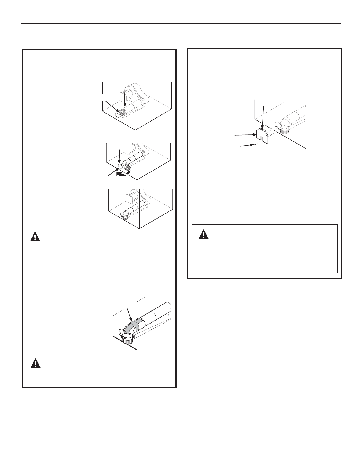
ADDING A NEW DUCT
• Reconnect the cut
portion A of the
duct to the blower
housing.
•
Tape the elbow
in a 90-degree
position to
prevent rotation.
•
Insert the elbow
through the rear hole
and connect it to
portion A. Rotate
the elbow through
the bottom opening.
Fixing hole
Portion “A”
Rear hole
Bottom
opening
Dryer Exhaust to the bottom of cabinet.
ADDING COVER PLATE TO REAR OF CABINET
(BOTTOM EXHAUST)
Tab
Cover Plate
Screw
Connect standard metal elbows and ducts to
complete the exhaust system. Cover back opening
with a cover plate (Cover Plate – WE1M454)
available from your local service provider.
Insert the tab at the top of the cover plate into the
opening. Fasten screw at the bottom of the cover
plate.
Place dryer in final location.
CAUTION: Be sure not to pull or
damage the electrical wires inside the dryer
when inserting the duct.
•
While still holding down
the pipe and elbow from
the rear opening, screw
the pipes in place with
the previously saved screw.
•
Apply duct tape
as shown on the joint
between the dryer internal
duct and the elbow.
NOTE: Make sure the tape
covers the screw hole in
portion A where it connects
to the elbow.
Duct tape
CAUTION: Internal duct joints must be
secured with tape; otherwise, they may separate
and cause a safety hazard.
WARNING – NEVER LEAVE
THE BACK OPENING WITHOUT THE PLATE.
COVER BACK OPENING WITH A COVER PLATE
(COVER PLATE – WE1M454) AVAILABLE FROM
YOUR LOCAL SERVICE PROVIDER.
23
Page 24
FINAL SETUP
1
LEVEL THE DRYER
Installation Instructions
4
DRYER STARTUP
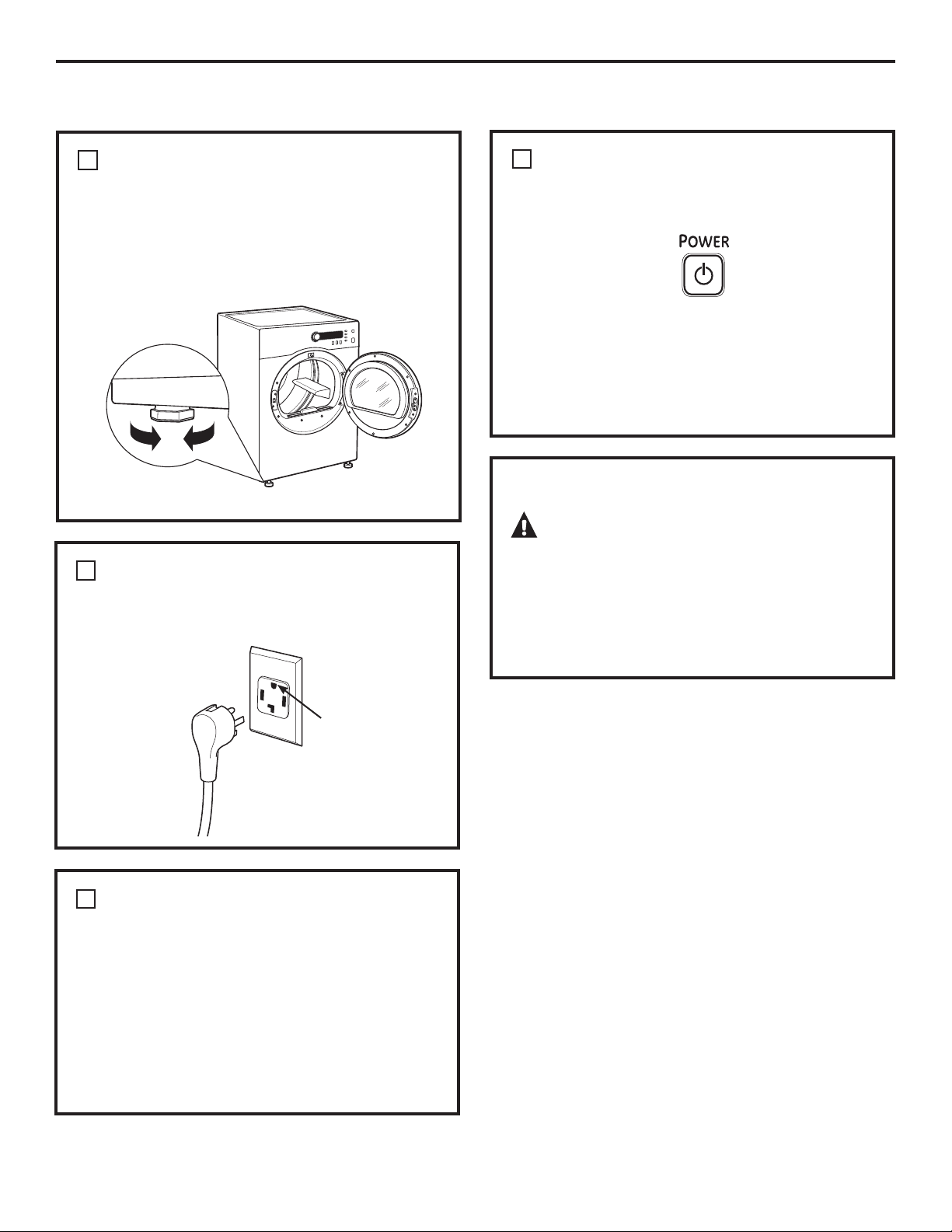
Stand the dryer upright near the final location
and adjust the four leveling legs at the corners
to ensure that the dryer is level from side to side
and front to rear.
Lower
2
PLUG DRYER IN
NOTE: Stacking installations may require a power
cord up to 6 feet in length.
Raise
Press the POWER button.
NOTE: If the dryer has been exposed to
temperatures below freezing for an extended
period of time, allow it to warm up before pressing
POWER. Otherwise, the display will not come on.
The dryer is now ready for use.
SERVICING
WARNING – Label all wires prior
to disconnection when servicing controls. Wiring
errors can cause improper and dangerous
operation after servicing/installation.
For replacement parts and other information,
refer to the back cover for servicing phone
numbers.
Ensure proper
ground exists
before use.
3
GROUNDING INSTRUCTIONS
This appliance must be grounded. In the event
of malfunction or breakdown, grounding will
reduce the risk of electric shock by providing
a path of least resistance for electric current.
This appliance is equipped with a cord having an
equipment-grounding conductor and a grounding
plug. The plug must be plugged into an appropriate
outlet that is properly installed and grounded in
accordance with all local codes and ordinances.
24
Page 25
Installation Instructions
REVERSING THE DOOR SWING (if desired)
IMPORTANT NOTES
• Read the instructions all the way through before
starting.
• Handle parts carefully to avoid scratching paint.
• Provide a nonscratching work surface for
the doors.
• Set screws down by their related parts to avoid
using them in the wrong places.
• All screws must be hand-tightened.
• Normal completion time to reverse the door
swing is 20–30 minutes.
IMPORTANT: Once you begin, do not move the
cabinet until door-swing reversal is completed.
These instructions are for changing the hinges
IURPWKHULJKWVLGHWRWKHOHIWVLGH³LI\RXHYHUZDQW
to switch them back to the right side, follow these
same instructions and reverse all references
to the left and right.
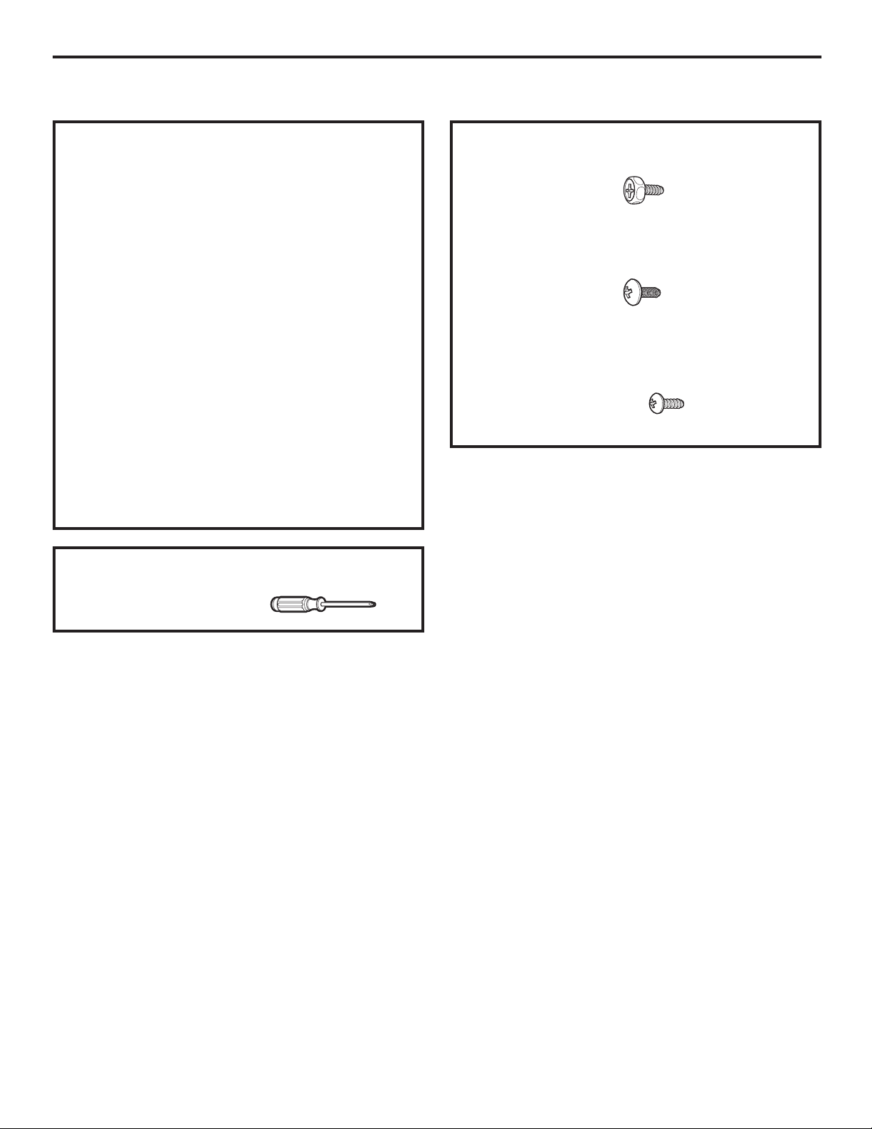
HARDWARE USED
Mounting Screw
Hinge Bracket
Anchoring Screws
Door and Latch Screws
TOOLS YOU WILL NEED
Phillips-head screwdriver
25
Page 26
Installation Instructions
REVERSING THE DOOR SWING (if desired)
2
BEFORE YOU START
DISASSEMBLE THE DOOR ASSEMBLY
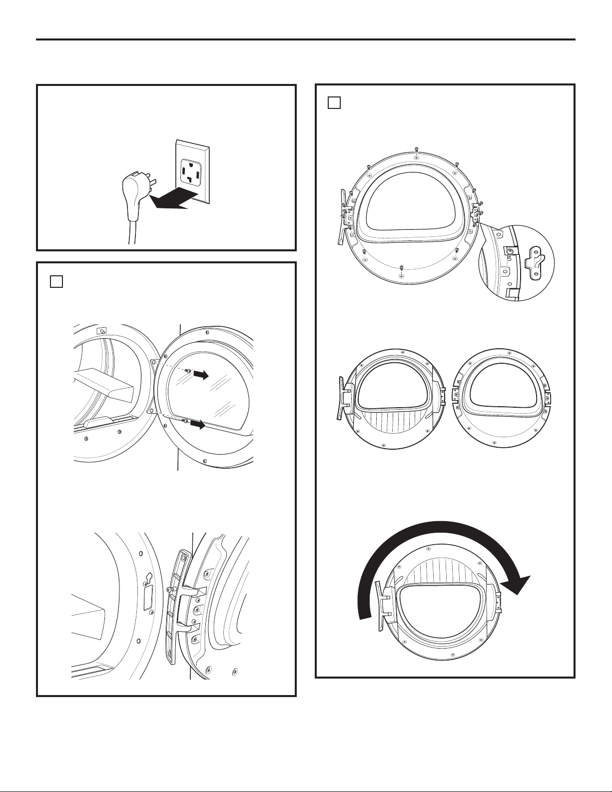
Unplug the dryer from its electrical outlet.
REMOVE THE DOOR ASSEMBLY
1
Remove hinge bracket anchoring screws.
Remove 16 door screws and male end of latch
from the inner side of the door.
Remove the inner face.
Slide door and hinge assembly upward; then
remove the assembly from the dryer front panel.
Lift and rotate the window assembly 180º and
replace. Also rotate the inner face 180° and
replace.
26
Page 27
Installation Instructions
3
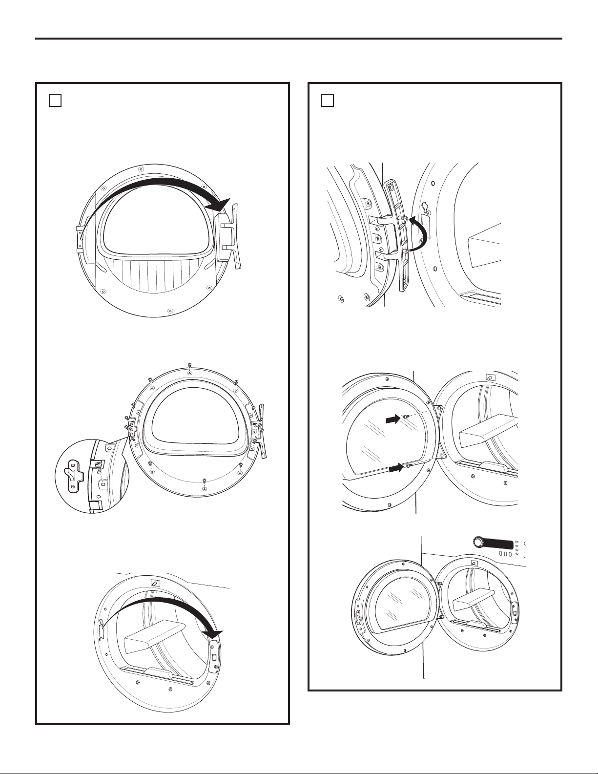
REPLACE DOOR ASSEMBLY
Replace a door screw in the center of the side
opposite the hinge. Then put the male end of the
latch into place and fasten with two door screws.
Replace all door screws that were removed.
3
REPLACE DOOR ASSEMBLY (CONT.)
Move the mounting screw to the upper screw hole
position on the hinge so that the door can be set
on the cabinet during final installation.
Fasten the hinge back on at the top and bottom
with the hinge mounting screws.
Remove the female end of the latch from the front
panel of the dryer, rotate 180° and replace on
the opposite side.
27
Page 28
Installation Instructions
STACKING THE WASHER AND DRYER (if desired)
If you are planning to stack the washer and dryer, order Stacking Kit number GE24STACK to be used for this dryer.
Kit sold separately.
BEFORE YOU BEGIN
Read these instructions completely and carefully.
IMPORTANT – Save these instructions
•
for local electrical inspector’s use.
IMPORTANT – Observe all governing
•
codes and ordinances.
•
Note to Installer – Be sure to leave these
instructions with the Consumer.
•
Note to Consumer – Keep these instructions
for future reference.
•
Service must be performed by a qualified
installer.
•
Proper installation is the responsibility of
the installer.
•
Stacking installations may require a power cord
up to 6 feet in length.
FOR YOUR SAFETY:
WARNING –
• Electric Shock Hazard. Disconnect power before
installing. Failure to do so could result in serious
injury or death.
• Potential Personal Injury. More than two people
are recommended to lift the dryer into position
because of its weight and size. Failure to do so
could result in personal injury or death.
MINIMUM CLEARANCE OTHER THAN
ALCOVE OR CLOSET INSTALLATION
Minimum clearance to combustible surfaces
and for air opening are: 0” both sides and 3” front
and rear. Consideration must be given to provide
adequate clearance for installation and service.
REQUIREMENTS FOR ALCOVE OR
CLOSET INSTALLATION
• Your dryer is approved for installation in
an alcove or closet, as stated on a label on
the dryer back.
The dryer MUST be vented to the outdoors. See
•
the EXHAUSTING THE DRYER section.
Minimum clearance between dryer cabinet and
•
adjacent walls or other surfaces is:
0” either side
3” front and rear
Minimum vertical space from floor to overhead
•
shelves, cabinets, ceilings, etc., is 67.7”.
Closet doors must be louvered or otherwise
•
ventilated and have at least 60 square inches
of open area equally distributed. If the closet
contains both a washer and a dryer, doors must
contain a minimum of 120 square inches of open
area equally distributed.
NOTE: WHEN THE EXHAUST DUCT IS LOCATED AT
THE REAR OF THE DRYER, MINIMUM CLEARANCE
FROM THE WALL IS 5.5 INCHES.
• Avoid Tipping and Rupture of Utility Services.
Dryer must be securely attached to the washer.
DO NOT place the washer on top of the dryer.
Failure to do so could result in personal injury/
death or property damage.
28
Page 29
Installation Instructions
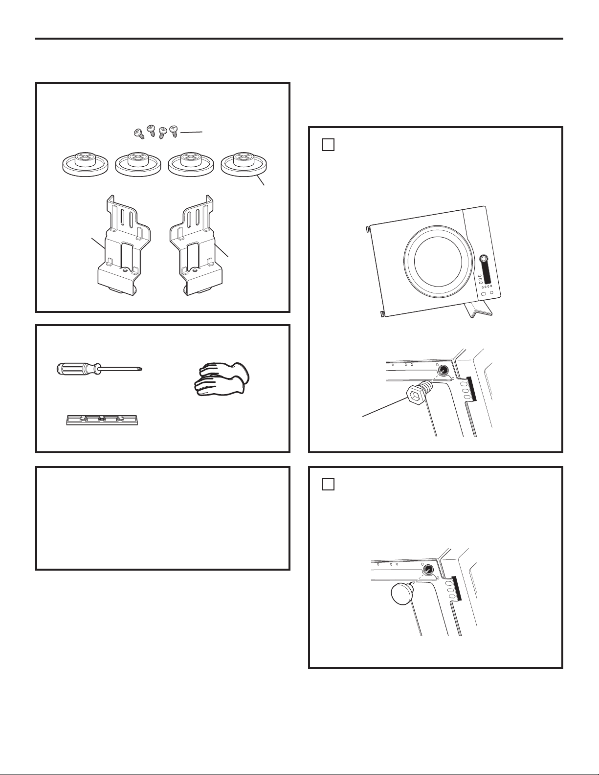
KIT CONTENTS (GE KIT #GE24STACK)
Screws (4)
Rubber
pads (4)
Bracketstack (R)
Bracketstack (L)
TOOLS YOU WILL NEED
INSTALLING THE STACK
BRACKET KIT
1
REMOVE THE DRYER LEVELING LEGS
A. Carefully lay the dryer on its side. Use the
packing material so you don’t scratch the finish
on the dryer.
B. Remove the dryer leveling legs.
Phillips screwdriver
Gloves
Level
INSTALLATION PREPARATION
Remove the packaging.
Flatten the product carton to use as a pad to lay the
dryer down on its side. Continue using the carton to
protect the finished floor in front of
the installation location.
Unscrew and remove
all 4 leveling legs
2
INSTALL RUBBER PADS
TO DRYER BASE
A. Locate the 4 rubber pads in the parts package.
Insert rubber pads into the leveling leg holes.
B. Set the dryer upright.
29
Page 30
Installation Instructions
STACKING THE WASHER AND DRYER (if desired) (cont.)
3
INSTALL BRACKET TO WASHER
A. Remove washer top cap screw from the rear
left. Align left bracket holes with top cap screw
hole on rear left of the unit and replace screw.
NOTE: Leave screws loose so dryer hole
alignment will be easier.
B. Drive next screw through the bracket into
the rear of the washer.
C. Repeat the above steps with the right side.
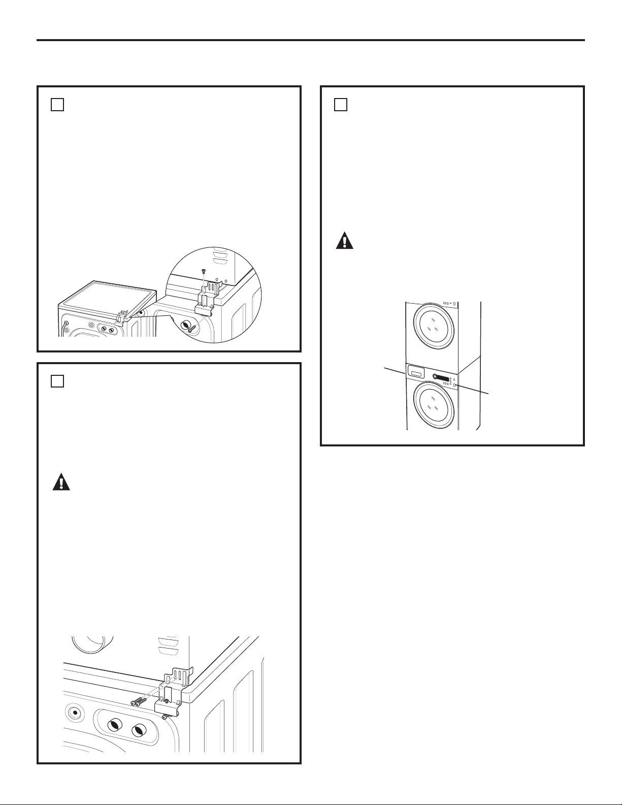
4
INSTALL DRYER AND BRACKET
ON DRYER
5
FINALIZE THE INSTALLATION
A. Refer to the washer Installation Instructions
to complete the washer installation.
B. Refer to the dryer Installation Instructions
to complete the dryer installation.
C. Carefully slide or walk the stacked washer and
dryer into place. Use felt pads or other sliding
device to assist moving and to protect flooring.
WARNING – Potential Personal
Injury. Do not push on the dryer once installed
to top of the washer. Pushing on the dryer may
result in pinched fingers.
Place
hands
here
Place
hands
here
A. Lift the dryer on top of the washer. Protect the
washer control panel with cardboard or other
protection. Be sure to lift the dryer high enough
to clear the washer control panel.
WARNING – Potential
Personal Injury. More than two people are
recommended to lift the dryer into position
because of its weight and size. Failure to do
so could result in personal injury or death.
B. Align the holes in the bracket with the holes
in the back of the dryer. Using a Phillips
screwdriver, attach the 2 #8 x 1/2” tapping
screws.
C. Tighten the dryer bracket screws; then tighten all
stacking kit screws.
30
Page 31

Notes. GEAppliances.com
31
Consumer SupportTroubleshooting TipsOperating InstructionsSafety Instructions
Page 32

Before you call for service…
Troubleshooting Tips
Save time and money! Review the charts on the following pages,
or visit GEAppliances.com. You may not need to call for service.
PROBLEM Possible Causes What To Do
Dryer shakes or Some shaking/noise is normal. • Move dryer to an even floor space, or adjust leveling legs
makes noise Dryer may be sitting unevenly as necessary until even.
Clothes take too long Improper or obstructed ducting • Check the Installation Instructions to make sure the
to dry dryer venting is correct.
• Make sure ducting is clean, free of kinks and
unobstructed.
• Check to see if outside wall exhaust hood operates
correctly and is clean.
Improper sorting • Separate heavy items from lightweight items (generally,
a well-sorted washer load is a well-sorted dryer load).
Large loads of heavy fabrics • Large, heavy fabrics contain more moisture and take
(like beach towels) longer to dry. Separate large, heavy fabrics into smaller
loads to speed drying time.
Controls improperly set • Match control settings to the load you are drying.
Lint filter is full • Clean lint filter before every load.
Blown fuses or tripped circuit • Replace fuses or reset circuit breakers. Since most
Operating Instructions Safety InstructionsConsumer Support Troubleshooting Tips
breaker dryers use 2 fuses/breakers, make sure both are
operating.
Overloading/combining loads • Do not put more than one washer load in the dryer at
a time.
Underloading • If you are drying only one or two items, add a few items
to ensure proper tumbling.
The DRY dryness level Load consists of a mixture • When combining heavy and light fabrics in a load,
was chosen but load is of heavy and light fabrics choose MORE DRY.
still damp
Exhaust system is blocked • Inspect and clean exhaust system.
Control pads not Controls accidentally put in • Press START/PAUSE.
responding service mode
Controls accidentally put in • Hold the LOCK button for 3 seconds to unlock the dryer.
lock mode
Controls performed an • Reset the in-house breaker.
incorrect operation
Dryer doesn’t start Control panel is “asleep” • This is normal. Press POWER to activate the control panel.
Dryer is unplugged • Make sure the dryer plug is pushed completely into
the outlet.
Fuse is blown/circuit breaker • Check the building’s fuse/circuit breaker box and
is tripped replace fuse or reset breaker. NOTE: Electric dryers
use two fuses or breakers.
Dryer was accidentally paused • If the light on the START/PAUSE button is flashing,
when starting Delay Start the dryer is paused. Press START/PAUSE to restart
the countdown.
32
Page 33

GEAppliances.com
PROBLEM Possible Causes What To Do
No numbers displayed Dryer is continuously • This is normal. When the dryer senses a low level of
during cycle, only lights monitoring the amount of moisture in the load, the dryer will display the dry time
moisture in the clothes remaining.
Time Remaining The estimated time may change • This is normal.
jumped to a when a smaller load than usual
lower number is drying
Cannot make a The DRYNESS LEVEL, TEMP • This is normal.
selection and the or OPTION that you are
dryer beeps twice trying to select is incompatible
with the chosen dry cycle
Dryer is running but The EXTEND TUMBLE • This is normal. During extended tumbling, the time
00 is displayed in option was chosen remaining is not displayed. The extended tumbling
Time Remaining option lasts approximately 20 minutes. It will then
tumble intermittently for approximately 70 minutes.
Clean Lint Filter (message) POWER button was activated • Press START/PAUSE to begin a dry cycle and the message
will disappear.
Dryer doesn’t heat Fuse is blown/circuit breaker • Check the building’s fuse/circuit breaker box and
is tripped; the dryer may tumble replace both fuses or reset both breakers. Your dryer
but not heat may tumble if only one fuse is blown or one breaker
tripped.
Inconsistent drying times Type of heat • Drying time will vary according to the type of heat used.
If you recently changed from an electric to a gas
(natural or LP) dryer, or vice versa, the drying time
could be different.
Type of load and • The load size, types of fabric, wetness of clothes and the
drying conditions length and condition of the exhaust system will affect
drying times.
Glow at the rear Heaters behind the drum • This is normal. Under certain drying conditions and
of the drum room ambient lighting, the glow of the heaters may be
visible at the rear of the drum.
Clothes are still wet The door was opened mid-cycle. • A dry cycle must be reselected each time a new load
and dryer shut off The load was then removed from is put in.
after a short time the dryer and a new load put in
without selecting a new cycle
Small load • When drying 3 items or less, choose SPEED DRY or
TIMED DRY.
Load was already dry except • Choose SPEED DRY or TIMED DRY to dry damp collars
for collars and waistbands and waistbands. In the future, when drying a load with
collars and waistbands, choose MORE DRY.
Dryer is not level • Move dryer to an even floor space or adjust leveling legs
as necessary until even.
Clothes are wrinkled Overdrying • Select a shorter drying time.
• Remove items while they still hold a slight amount of
moisture. Select a LESS DRY or DAMP setting.
Letting items sit in dryer after • Remove items when cycle ends and fold or hang
cycle ends immediately, or use the EXTEND TUMBLE option.
Overloading • Separate large loads into smaller ones.
Consumer SupportTroubleshooting TipsOperating InstructionsSafety Instructions
33
Page 34

Before you call for service…
Troubleshooting Tips.
PROBLEM Possible Causes What To Do
Clothes shrink Some fabrics will naturally shrink • To avoid shrinkage, follow garment care labels exactly.
when washed. Others can be
safely washed, but will shrink
in the dryer
item, do not machine wash or tumble dry it.
Greasy spots on clothes Improper use of fabric softener • Follow directions on fabric softener package.
Drying dirty items • Use your dryer to dry only clean items. Dirty items can
with clean ones stain clean items and the dryer.
Clothes were not • Sometimes stains which cannot be seen when the
completely clean clothes are wet appear after drying. Use proper washing
procedures before drying.
Lint on clothes Lint filter is full • Clean lint screen before each load.
Improper sorting • Sort lint producers (like chenille) from lint collectors
(like corduroy).
Static electricity can attract lint • See suggestions in this section under STATIC.
Operating Instructions Safety InstructionsConsumer Support Troubleshooting Tips
Overloading • Separate large loads into smaller ones.
Paper, tissue, etc., left in pockets • Empty all pockets before laundering clothes.
• Some items may be pressed back into shape after drying.
• If you are concerned about shrinkage in a particular
Static occurs No fabric softener was used • Try a fabric softener.
®
• Bounce
approved for use in all GE Dryers when used in
accordance with the manufacturer’s instructions.
Overdrying • Try a fabric softener.
• Adjust setting to LESS DRY or DAMP.
Synthetics, permanent press • Try a fabric softener.
and blends can cause static
Collars and waistbands The dryness monitor senses • Choose SPEED DRY or TIMED DRY to dry damp collars
still wet at end of cycle that the body of the clothes and waistbands. In the future, when drying a load with
is dry collars and waistbands, choose MORE DRY.
Slight variation This is normal • Due to the metallic properties of paint used for this unique
in metallic color product, slight variations of color may occur due to viewing
angles and lighting conditions.
Fabric Conditioner Dryer Sheets have been
34
Page 35

GE Dryer Warranty. (For customers in the United States)
All warranty service provided by our Factory Service Centers,
®
or an authorized Customer Care
technician. To schedule service
on-line, visit us at GEAppliances.com, or call 800.GE.CARES
(800.432.2737).
Staple your receipt here.
Proof of the original purchase
date is needed to obtain service
under the warranty.
Please have serial number and model number available when
calling for service.
For The Period Of: We Will Replace:
One Year Any part of the dryer which fails due to a defect in materials or workmanship. During this
From the date of the limited one-year warranty, GE will also provide, free of charge, all labor and related service costs
original purchase to replace the defective part.
What Is Not Covered (in the United States):
Service trips to your home to teach you how to use
the product.
Improper installation, delivery or maintenance.
Failure of the product if it is abused, misused or used for
other than the intended purpose or used commercially.
Replacement of the light bulb after its expected
useful life.
Damage to the product caused by accident, fire, floods
or acts of God.
Incidental or consequential damage caused by possible
defects with this appliance.
Damage caused after delivery.
Product not accessible to provide required service.
Replacement of house fuses or resetting of circuit
breakers.
(;&/86,212),03/,(':$55$17,(6³<RXUVROHDQGH[FOXVLYHUHPHG\LVSURGXFWUHSDLUDVSURYLGHGLQ
this Limited Warranty. Any implied warranties, including the implied warranties of merchantability or
fitness for a particular purpose, are limited to one year or the shortest period allowed by law.
This warranty is extended to the original purchaser and any succeeding owner for products purchased
for home use within the USA. If the product is located in an area where service by a GE Authorized Servicer
is not available, you may be responsible for a trip charge or you may be required to bring the product to an
Authorized GE Service location for service. In Alaska, the warranty excludes the cost of shipping or service calls
to your home.
Some states do not allow the exclusion or limitation of incidental or consequential damages. This warranty
gives you specific legal rights, and you may also have other rights which vary from state to state. To know
what your legal rights are, consult your local or state consumer affairs office or your state’s Attorney General.
Warrantor: General Electric Company. Louisville, KY 40225
Consumer SupportTroubleshooting TipsOperating InstructionsSafety Instructions
35
Page 36

GE Dryer Warranty. (For customers in Canada)
All warranty service provided by our Factory Service Centres or an authorized
technician. For service, call 1.800.561.3344.
Please have serial number and model number available when calling for service.
For The Period Of: We Will Replace:
One Year Any part of the dryer which fails due to a defect in materials or workmanship. During this
From the date of the limited one-year warranty, GE will also provide, free of charge, all labor and related service costs
original purchase to replace the defective part.
What Is Not Covered (in Canada):
Service trips to your home to teach you how to use
the product.
Improper installation, delivery or maintenance.
Failure of the product if it is abused, misused or used for
other than the intended purpose or used commercially.
Replacement of the light bulb after its expected
useful life.
Replacement of house fuses or resetting of circuit
breakers.
Damage to the product caused by accident, fire, floods
or acts of God.
Incidental or consequential damage caused by possible
defects with this appliance.
Damage caused after delivery.
Product not accessible to provide required service.
Operating Instructions Safety InstructionsConsumer Support Troubleshooting Tips
(;&/86,212),03/,(':$55$17,(6³<RXUVROHDQGH[FOXVLYHUHPHG\LVSURGXFWUHSDLUDVSURYLGHGLQWKLV/LPLWHG
Warranty. Any implied warranties, including the implied warranties of merchantability or fitness for a particular
purpose, are limited to one year or the shortest period allowed by law.
This warranty is extended to the original purchaser and any succeeding owner for products purchased in
Canada for home use within Canada. In-home warranty service will be provided in areas where it is available
and deemed reasonable by Mabe to provide.
WARRANTOR IS NOT RESPONSIBLE FOR CONSEQUENTIAL DAMAGES.
36
Warrantor: MABE CANADA INC.
Page 37

Mesures de sécurité ................ 38–40
Foncionnement
Options de cycle ....................................44, 45
Panneau de contrôle ........................ 41–43
Utilisation de la sécheuse ......................46
Installation
Avant de commencer ........................47, 48
Emplacement
de votre sécheuse ..............................48, 49
Évacuation de la sécheuse .......... 53–59
Installation finale ...........................................60
Inversion de l’ouverture
de la porte ................................................ 61–63
Raccordement
d’une sécheuse électrique .............50–52
Superposer la laveuse
à la sécheuse ........................................ 64–66
Conseils de dépannage ....... 67–69
Soutien au consommateur
Garantie .......................................................... 70
Soutien au
consommateur ............................................ 72
CONSERVEZ CES DIRECTIVES
Inscrivez ici les numéros
de modèle et de série :
Modèle N° ________________
Série N° __________________
Ces informations figurent
sur l’étiquette située à l’avant
de la sécheuse, derrière la porte.
Soutien au consommateurConseils de dépannageFonctionnementMesures de sécurité
37
Page 38

MESURES DE SÉCURITÉ IMPORTANTES.
LISEZ D’ABORD TOUTES LES DIRECTIVES.
AVERTISSEMENT!
Pour votre sécurité, suivez les directives fournies dans le présent manuel afin
de minimiser les risques d’incendie, d’explosion et de chocs électriques et prévenir
des dégâts matériels et des blessures graves ou mortelles.
N’entreposez pas ou n’utilisez pas
d’essence ou autres vapeurs ou
liquides inflammables à proximité
de cet appareil ou de tout autre
électroménager.
UNE INSTALLATION ADÉQUATE
Avant d’utiliser votre sécheuse, assurez-vous qu’elle a été adéquatement installée, conformément
aux Instructions d’installation. Les consignes d’installation figurent au dos de ce manuel.
Mettez l’appareil à la terre conformément à tous
les codes et règlements en vigueur. Suivez les Directives
Fonctionnement Mesures de sécuritéSoutien au consommateur Conseils de dépannage
d’installation.
Installez ou entreposez l’appareil dans une pièce
où la température est supérieure à 0°C, et où il sera
à l’abri des intempéries,
l’appareil et invalider la garantie.
Branchez l’appareil sur un circuit protégé et de capacité
appropriée afin d’éviter toute surcharge électrique.
Retirez tous les articles d’emballage tranchants et jetez
tous les matériaux de transport.
qui pourraient endommager
L’installation et les réparations doivent
être effectuées par un installateur
qualifié, une entreprise de réparation
ou votre fournisseur de gaz.
Conduit d’évacuation :
1
L’air des sécheuses DOIT être évacué à l’extérieur pour
empêcher que de grandes quantités d’humidité et de
charpie soient envoyées dans la pièce.
2
Utilisez uniquement des conduits métalliques rigides,
d’un diamètre de 4 po, à l’intérieur de la carrosserie de
la sécheuse. Utilisez uniquement un conduit métallique
rigide ou flexible de 4 po de diamètre pour l’évacuation
vers l’extérieur. N’utilisez jamais un conduit en plastique
ou autre matériau combustible facilement perforable.
Pour des détails complets, suivez les Instructions
d’installation.
38
Page 39

www.electromenagersge.ca
AVERTISSEMENT!
AUTOUR DE VOTRE SÉCHEUSE
Conservez la zone sous et autour de vos appareils libre
de tous matériaux combustibles (charpies, papiers,
chiffons, etc.), essence, produits chimiques et autres gaz
et liquides inflammables.
Gardez le sol propre et sec à proximité de vos
électroménagers afin de ne pas glisser.
Il faut exercer une étroite surveillance lorsque
vous faites fonctionner cet appareil en présence
d’enfants. Ne les laissez pas jouer sur, avec ou
dans cet appareil ou dans tout autre appareil.
LORSQUE VOUS UTILISEZ LA SÉCHEUSE
Ne vous penchez jamais dans la sécheuse pendant
que le tambour tourne. Avant de charger ou de
décharger la sécheuse ou d’y ajouter des vêtements,
attendez que le tambour se soit complètement arrêté.
Avant chaque séchage, nettoyez le filtre à charpie afin
de prévenir l’accumulation de charpie à l’intérieur
de la sécheuse ou dans la pièce. NE FAITES PAS
FONCTIONNER LA SÉCHEUSE SANS LE FILTRE
À CHARPIE.
Ne lavez pas ou ne faites pas sécher des articles qui ont
été lavés avec des produits combustibles ou explosifs,
ou qui ont été trempés dans ces produits ou qui en
sont tachés (cire, peinture, huile, essence, dégraissants,
solvants pour le nettoyage à sec, kérosène, etc.). Ces
substances émettent des vapeurs qui peuvent prendre
feu ou exploser. Ne versez pas ces substances dans l’eau
de la laveuse. N’utilisez pas ces substances à proximité
de votre laveuse ou de votre sécheuse pendant qu’elles
fonctionnent.
Ne rangez pas dans votre sécheuse des articles qui
ont été en contact avec des huiles de cuisson; ceux-ci
peuvent provoquer une réaction chimique susceptible
de faire s’enflammer vos vêtements.
Il ne faut pas mettre dans la sécheuse, ou à proximité
de celle-ci, tout article ayant été utilisé avec un solvant
dégraissant ou contenant une substance inflammable
(comme des chiffons de nettoyage, des vadrouilles,
des serviettes utilisées dans les salons de coiffure, etc.),
à moins qu’ils aient été débarrassés de toute trace et
de toute vapeur de substance inflammable. On utilise
à la maison de nombreux produits inflammables :
acétone, alcool dénaturé, essence, kérosène, nettoyants
ménagers, détachants, térébenthine, cire, décapants,
contenant du distillat de pétrole.
La lessive peut atténuer les propriétés ignifugeantes
des tissus. Pour éviter cette situation, suivez à la lettre
les directives données par le fabricant du vêtement.
Assurez-vous qu’il n’y ait aucune accumulation
de charpie, de poussière ou de saleté autour
et à proximité de l’orifice d’évacuation.
Gardez tous les produits pour la lessive (comme
les détersifs, les javellisants, etc.) hors de la portée des
enfants, de préférence dans une armoire fermée à clef.
Suivez toutes les mises en garde sur les étiquettes pour
éviter des blessures.
Ne montez jamais sur le dessus de la sécheuse.
Ne faites pas sécher des articles contenant du
caoutchouc, du plastique, de la mousse ou autres
matériaux similaires (comme des soutiens-gorge
préformés, des chaussures de tennis, des caoutchoucs,
des tapis de bain, des carpettes, des bavoirs, des culottes
de bébé, des sacs de plastique, des oreillers, etc.),
car ces matériaux peuvent fondre ou brûler. De plus,
dans certaines circonstances, certains matériaux de
caoutchouc peuvent causer un incendie par combustion
spontanée lorsqu’ils sont chauffés.
Ne rangez pas des articles qui peuvent fondre ou brûler,
comme du plastique, du papier, ou des vêtements sur
le dessus de la sécheuse pendant qu’elle fonctionne.
Les vêtements portant la mention «Faire sécher loin
de la chaleur» ou «Ne pas faire sécher par culbutage»
(comme les gilets de sauvetage contenant du Kapok)
ne doivent pas être séchés dans votre sécheuse.
Ne faites pas sécher d’articles en fibre de verre
dans votre sécheuse. Les particules qui restent dans
la sécheuse et qui pourraient être recueillies par
les vêtements lors d’un séchage subséquent risquent
de causer des irritations cutanées.
Pour réduire les risques de chocs électriques,
débranchez toujours l’appareil ou coupez l’alimentation
électrique au panneau de distribution en enlevant
le fusible ou en déclenchant le disjoncteur avant de
le réparer ou de le nettoyer (sauf pour enlever et
nettoyer le filtre à charpie). REMARQUE : Le fait d’appuyer
sur START/PAUSE (MISE EN MARCHE/PAUSE) ou POWER
(ALIMENTATION) NE coupe PAS l’alimentation électrique
à l’appareil.
Soutien au consommateurConseils de dépannageFonctionnementMesures de sécurité
39
Page 40

MESURES DE SÉCURITÉ IMPORTANTES.
LISEZ D’ABORD TOUTES LES DIRECTIVES.
AVERTISSEMENT!
LORSQUE VOUS UTILISEZ LA SÉCHEUSE (SUITE)
Ne faites pas fonctionner l’appareil s’il est
endommagé, défectueux, partiellement
démonté ou si des pièces sont manquantes
ou défectueuses, ou si le cordon d’alimentation
ou la fiche sont endommagés.
L’intérieur de l’appareil et le raccord du conduit
d’évacuation à l’intérieur de la sécheuse doivent
être nettoyés une fois par an par une personne
qualifiée. Voyez les conseils pour le tri
et le chargement en page 46.
Fonctionnement Mesures de sécuritéSoutien au consommateur Conseils de dépannage
LORSQUE VOTRE SÉCHEUSE N’EST PAS EN MARCHE
Lorsque vous débranchez l’appareil, tirez sur
la fiche et non pas sur le cordon afin d’éviter
d’endommager le cordon d’alimentation. Installez
le cordon de sorte que personne ne marche ou
ne trébuche dessus, ou qu’il ne soit pas exposé
à des dommages.
Il est possible que vous désiriez assouplir votre
lessive ou réduire le collement électrostatique
en utilisant un assouplissant textile dans votre
sécheuse ou un produit antistatique. Nous vous
recommandons d’utiliser un assouplissant liquide
au cours du programme de lavage, conformément
aux directives du fabricant de ce type de produit,
ou de faire l’essai d’un assouplissant textile pour
la sécheuse, pour lequel le fabricant certifie
sur l’emballage que son produit peut être
utilisé en toute sécurité dans la sécheuse. La
responsabilité des problèmes de rendement ou de
fonctionnement qui ne sont pas couverts par
la garantie de cet appareil et sont attribuables
à l’utilisation de ces produits relève du fabricant
de ces produits.
Avant de jeter ou d’entreposer une sécheuse,
enlevez toujours la porte afin d’empêcher
les enfants de se cacher à l’intérieur.
Ne trafiquez pas les commandes de l’appareil.
Ne réparez ou ne remplacez aucune pièce de cet
appareil, à moins que cela ne soit spécifiquement
recommandé dans le présent manuel ou dans
des directives de réparation que vous comprenez
et que vous êtes en mesure de suivre.
VEUILLEZ LIRE ET SUIVRE ATTENTIVEMENT CES MESURES
DE SÉCURITÉ.
CONSERVEZ CES DIRECTIVES
40
Page 41

À propos du panneau de contrôle de la sécheuse.
www.electromenagersge.ca
AVERTISSEMENT! Afin de réduire le risque d’incendie, de décharge électrique,
ou de blessure, lisez les MESURES DE SÉCURITÉ IMPORTANTES
avant de mettre cet appareil en marche.
Dans ce manuel, les caractéristiques et l’apparence peuvent varier selon votre modèle.
Démarrage
Si l’écran est noir, appuyez sur la touche POWER
(ALIMENTATION) afin de réactiver l’affichage.
1
Appuyez sur
POWER (ALIMENTATION)
2
Sélectionnez un cycle
en tournant
Cycle.
3
Si vous avez sélectionné SENSOR
DRY CYCLE (CYCLE PAR
SÉCHAGE CAPTEUR) – appuyez
simplement
sur
la touche
EN MARCHE/PAUSE).
la touche
le bouton
START/PAUSE (MISE
.
Si vous avez sélectionné un
cycle TIME DRY (SÉCHAGE
MINUTÉ)³VpOHFWLRQQH]OD
température et la durée de
séchage pour vos articles en
appuyant sur la touche TIME
(DURÉE) jusqu’à affichage du
temps souhaité. Puis appuyez
sur la touche START/PAUSE
(MISE EN MARCHE/PAUSE).
Power (alimentation)
1
Appuyez sur cette touche pour « allumer » l’écran. Si l’écran est actif, appuyez pour éteindre
la sécheuse.
REMARQUE : Le fait d’appuyer sur POWER (ALIMENTATION) ne coupe pas l’alimentation électrique
à l’appareil.
Soutien au consommateurConseils de dépannageFonctionnementMesures de sécurité
41
Page 42

A propos du panneau de contrôle de la sécheuse.
Dry Cycles (cycles de séchage)
2
Le cycle de séchage contrôle la durée du processus de séchage. Le tableau ci-dessous vous aidera à
trouver le bon réglage de séchage en fonction de votre brassée.
Cycles par capteur
COTTONS (cotons) Pour les cotons et la plupart des articles en toile.
MIXED LOAD Pour les brassées constituées de cotons et de mélanges de polyester.
(mixte)
WRINKLE FREE Pour les articles infroissables/entretien facile et sans repassage.
(infroissables)
ACTIVE WEAR Pour les vêtements de sports, d’exercice et certains vêtements décontractés. Les tissus
(vêtements de sport) bénéficient de finitions en nouvelle technologie et sont composés de fibres élastiques
DELICATES Pour la lingerie et les tissus délicats.
(délicats)
SPEED DRY Pour les petites brassées qui doivent être séchées rapidement, comme les tenues de
(séchage rapide) sport ou les uniformes d’école. Ce cycle peut aussi être utilisé si le cycle précédent a laissé
Timed Dry Cycles (cycles de séchage minuté)
WARM UP Fournit 10 minutes de réchauffage des vêtements.
(réchauffage)
Fonctionnement Mesures de sécuritéSoutien au consommateur Conseils de dépannage
DEWRINKLE Pour supprimer les plis des articles qui sont secs ou légèrement humides. Ce cycle n’est pas
(défroisser) recommandé pour les tissus délicats.
comme le Spandex.
quelques articles encore humides, comme des cols ou des ceintures.
AIR FLUFF Utilisez ce cycle pour faire culbuter les articles sans chaleur.
(duvetage)
Timed Dry (séchage minuté)
3
Utilisé pour ajuster votre propre temps de séchage. TIMED DRY (séchage minuté) est également
recommandé pour les petites charges.
Pour utiliser TIMED DRY (séchage minuté) :
1. Faites tourner le bouton des cycles de séchage sur TIMED DRY (séchage minuté).
2. Sélectionner la durée du séchage en appuyant sur la touche TIME (DURÉE). Vous pouvez augmenter
la durée par incréments de 10 minutes jusqu’au maximum de 1 heure et 20 minutes.
3. Sélectionnez DRY TEMP (TEMPÉRATURE DE SÉCHAGE).
4. Fermez la porte.
5. Appuyez sur START/PAUSE (MISE EN MARCHE/PAUSE).
Sensor Dry Level (détection du niveau d’humidité)
4
Le détecteur surveille en permanence le niveau d’humidité dans le linge. Quand l’humidité dans
vos vêtements atteint le niveau de séchage que vous avez choisi, la sécheuse s’arrête.
EXTRA DRY Utilisé pour les tissus résistants ou les articles qui ont besoin d’être très secs,
(extra sec) comme par exemple les serviettes.
MORE DRY (plus sec) Utilisé pour les types de tissus lourds ou mélangés.
DRY (sec) Utilisé pour un niveau de séchage normal adapté à la plupart des brassées. C’est le cycle
recommandé pour un fonctionnement en économie d’énergie.
42
LESS DRY (moins sec) Utilisé pour les tissus plus légers (idéal pour le repassage).
DAMP (humide) Pour laisser les articles partiellement humides.
REMARQUE : Le Sensor Dry Level (Détection du niveau d’humidité) ne peut être sélectionné qu’avec un cycle
Sensor Dry (Détection de l’humidité).
Page 43

Dry Temp (température de séchage)
5
Vous pouvez modifier la température de votre cycle de séchage.
ANTI-BACTERIAL Cette option peut uniquement être utilisée avec les cycles COTTONS (COTONS) ou MIXED
(anti-bactérien) LOAD (CHARGE MIXTE). Cette option permet de diminuer la possibilité que certains types de
REMARQUE : N’utilisez pas ce cycle pour des tissus délicats.
HIGH (haute) Pour les cotons normaux à lourds.
MEDIUM (moyenne) Pour les synthétiques, les mélanges et les articles étiquetés sans repassage.
bactéries soient présentes. Le processus antibactérien se produit quand des températures
élevées sont mises en oeuvre pendant une partie de ce cycle de séchage.
www.electromenagersge.ca
LOW (basse) Pour les tissus délicats, synthétiques et les articles étiquetés Tumble Dry Low (séchage par
EXTRA LOW Pour la lingerie et les tissus délicats.
(extra basse)
START/PAUSE (MISE EN MARCHE/PAUSE)
6
Appuyez sur cette touche pour lancer un cycle de séchage. Si la sécheuse est déjà en fonctionnement, le fait
d’appuyer sur cette touche interrompt le cycle en cours. Appuyez encore sur la touche pour reprendre le cycle
de séchage.
culbutage à basse température).
« CLEAN LINT FILTER » (Nettoyage du filtre à charpie) (message)
Ce message reste affiché jusqu’à la mise en marche. Ce message est uniquement un rappel.
43
Soutien au consommateurConseils de dépannageFonctionnementMesures de sécurité
Page 44

Options de cycle.
REMARQUE :
Certaines caractéristiques peuvent ne pas être offertes sur tous les modèles de sécheuses.
Fonctionnement Mesures de sécuritéSoutien au consommateur Conseils de dépannage
Extend Tumble (Culbutage prolongé)
Réduit le froissement en ajoutant environ
20 minutes de culbutage sans chauffage
suivi de 70 minutes de culbutage sans
chauffage par intermittence après séchage
des vêtements. La sécheuse est en mode
EXTENDED TUMBLE (culbutage prolongé)
quand l’affichage ESTIMATED CYCLE TIME
(temps de cycle estimé) est illuminé dans
une façon circulaire.
Damp Alert (Alerte d’humidité)
Cette option fait sonner la sécheuse quand
les vêtements ont été séchés jusqu’à un
certain niveau d’humidité. Retirez les articles
que vous souhaitez étendre pour sécher.
L’ALERTE DU NIVEAU D’HUMIDITÉ (damp
alert) retentira uniquement quand cette
option est sélectionnée (le cycle de séchage
sec se poursuit).
Le voyant dans la touche sera allumé lorsque
l’EXTEND TUMBLE (culbutage prolongé) est
activé.
REMARQUE : Il est normal que le tambour
s’arrête à intervalles réguliers pendant
l’EXTEND TUMBLE (culbutage prolongé).
Le fait de retirer les vêtements et les étendre
quand ils sont humides peut diminuer le
besoin de repasser certains articles.
Le voyant dans la touche sera allumé lorsque
l’option DAMP ALERT est sélectionnée.
REMARQUE : Uniquement pour les
sélections de séchage DRY (sec), MORE DRY
(plus sec) et EXTRA DRY (très sec).
Delay Start (Mise en marche différée)
Utilisez pour retarder le démarrage de votre
sécheuse.
1. Sélectionnez votre cycle de séchage et
toutes les options.
2. Appuyez sur la touche DELAY START
(MISE EN MARCHE DIFFÉRÉE). Vous pour
modifiez le délai par incrément d’1 heure
(jusqu’à 18 heures) chaque fois que vous
appuyez sur la touche DELAY START (MISE
EN MARCHE DIFFÉRÉE). Arrêtez d’appuyer
sur la touche lorsque le délai requis
s’affiche.
3. Appuyez sur la touche START/PAUSE
(MISE EN MARCHE/PAUSE) pour lancer
le compte à rebours.
Le compte à rebours sera indiqué sur
l’affichage « ESTIMATED TIME REMAINING »
(temps restant estimé).
REMARQUES :
Si la porte est ouverte alors que
la sécheuse est en mode DELAY (MISE
EN MARCHE DIFFÉRÉE), le compte à
rebours va se poursuivre. Si la porte n’est
pas fermée et que le compte à rebours
expire, le cycle ne redémarrera que
si la porte est fermée et que le bouton
START/PAUSE (MISE EN MARCHE/PAUSE)
est enfoncé.
Vous pouvez retarder le démarrage d’un
cycle de séchage jusqu’à 18 heures.
Le voyant dans la touche sera allumé lorsque
DELAY START (MISE EN MARCHE DIFFÉRÉE)
est sélectionné.
44
Page 45

www.electromenagersge.ca
Lock (Verrouillage)
Vous pouvez verrouiller les commandes
pour en éviter la sélection. Ou vous pouvez
verrouiller les commandes après le
démarrage d’un cycle.
Avec cette option sélectionnée, les enfants
ne peuvent plus démarrer la sécheuse
accidentellement en appuyant sur les touches.
Pour verrouiller les commandes de
la sécheuse, appuyez et maintenez
appuyées les touches TEMP (TEMP)
et SENSOR (CAPTEUR) simultanément
pendant 3 secondes.
Pour déverrouiller les commandes de
la sécheuse, appuyez et maintenez
appuyées les touches TEMP (TEMP)
et SENSOR (CAPTEUR) simultanément
pendant 3 secondes. Un bip sonore vous
indiquera l’état de verrouillage ou de
déverrouillage de la sécheuse.
L’icône de verrouillage des commandes
sera allumé lorsque les commandes sont
verrouillées.
REMARQUE : La touche POWER
(ALIMENTATION) peut encore être utilisé
lorsque la machine est verrouillée.
FonctionnementMesures de sécurité
Signal
Lorsque le voyant est allumé, la sécheuse
émettra un bip sonore à la fin du cycle
et à chaque fois que vous appuierez sur
une touche du panneau de contrôle.
Pour désactiver le signal, appuyez sur
la touche SIGNAL et le voyant s’éteindra.
Conseils de dépannage
Soutien au consommateur
45
Page 46

Utilisation de la sécheuse.
Suivez toujours l’étiquette du fabricant de tissus pour laver.
Fonctionnement Mesures de sécuritéSoutien au consommateur Conseils de dépannage
Conseils pour le tri
et le chargement
En règle générale, lorsque les vêtements sont
correctement triés pour le lavage, ils le sont aussi
pour le séchage. Essayez aussi de trier les articles
en fonction de leur taille. Par exemple, ne séchez
pas un drap avec des chaussettes ou d’autres
petits articles.
N’ajoutez pas votre feuille d’assouplissant
textile lorsque la brassée a commencé à
chauffer, car elle risque de provoquer des taches
d’assouplissant. Les feuilles d’assouplissant
de tissus Bounce
MD
pour sécheuses ont été
Étiquettes d’entretien de tissu
Ci-dessous figurent les « symboles » des
étiquettes d’entretien de tissu qui concernent
le linge à sécher.
Étiquettes de séchage
Séchage
Tumble
par
dry
culbutage
Dry
Séchage
Normal Doux/
Normal
Sans repassage/
Permanent Press/
wrinkle resistant
infroissables
approuvées pour cette sécheuse si elles sont
utilisées conformément aux instructions
du fabricant.
Voir ci-dessous pour les consignes de nettoyage
du filtre à charpie.
Ne surchargez pas. Ceci consomme inutilement
de l’énergie et cause des faux plis.
Ne séchez pas les articles suivants : Articles
en fibre de verre, lainages, articles recouverts
de caoutchouc, plastiques, articles dotés
d’une garniture en plastique, articles remplis
de mousse de caoutchouc.
Gentle/
delicate
délicat
Ne pas sécher
Do not tumble dry
par culbutage
Do not dry
Ne pas sécher
(used with
do not wash)
(utilisé avec
ne pas laver)
46
Réglage
Heat
de chaleur
setting
Special
Instructions
instructions
spéciales
Haut Moyen Bas Pas de chaleur/
High
Sécher en suspendant
Medium
Line dry/
hang to dry
après essorage
Low
Drip dry
Sécher par
égouttage
Entretien et nettoyage
de la sécheuse
Intérieur de la sécheuse et conduit : L’intérieur
de la machine et du conduit d’évacuation doit
être nettoyé une fois par
an par du personnel de service qualifié.
Extérieur : Essuyez les produits de lessive
renversés, et enlevez la poussière avec un linge
humide. Le fini et le panneau de contrôle
de la sécheuse peuvent être endommagés
par certains produits de traitement préliminaire
et détachants. Appliquez ces produits loin
de la sécheuse. Vous pouvez ensuite laver
et faire sécher les vêtements normalement.
Les dommages causés à votre sécheuse par
ces produits ne sont pas couverts par votre
garantie.
Ne touchez pas la surface ou l’écran avec
des objets pointus.
Filtre à charpie : Nettoyez le filtre à charpie
avant chaque utilisation. Sortez-le en le tirant
vers le haut. Ouvrez le filtre et faites passer
vos doigts sur le filtre. Un amas cireux peut
se former sur le filtre à charpie à cause de
l’utilisation des feuilles d’assouplissant textile.
Pour éliminer cet amas, lavez le filtre à l’eau
chaude savonneuse. Séchez-le soigneusement
No heat/air
aération
Dry flat
Sécher à plat Sécher à l’ombre
et replacez-le. N’utilisez pas la sécheuse sans le
filtre à charpie en place.
Aspirez la charpie de la zone du filtre à charpie
si vous remarquez une modification des
performances de la sécheuse.
Acier inoxydable : Pour nettoyer les
surfaces en acier inoxydable, utilisez un
chiffon humidifié avec un nettoyant doux et
non abrasif, adapté aux surfaces en acier
inoxydable. Éliminez les résidus de nettoyant,
puis séchez avec un chiffon propre.
L’acier inoxydable utilisé pour fabriquer
le tambour de séchage fournit la plus haute
fiabilité disponible dans une sécheuse GE.
Si le tambour de séchage est rayé ou ébréché
pendant une utilisation normale, le tambour
ne rouillera pas ou ne se corrodera pas.
Ces défauts de surface n’affecteront pas
le fonctionnement ou la durabilité du tambour.
Évent d’evacuation : Vérifiez avec un miroir
que les volets à l’intérieur de l’évent se
déplacent librement lors du fonctionnement.
Assurez-vous qu’aucun animal (oiseaux,
insectes, etc.) ne s’est introduit dans le conduit
ou l’évent.
In the shade
Page 47

Instructions
Sécheuse
d’installation
Des questions? Appelez le 1.800.561.3344 ou Visitez notre site Web à l’adresse : www.electromenagersge.ca
DCVH480EK, DCVH485EK, PCVH480EK, PCVH485EK
Si vous prévoyez placer la laveuse et la sécheuse
en superposition, commandez le nécessaire de
superposition no° GE24STACK à utiliser avec cette
sécheuse. Le nécessaire est vendu séparément.
AVANT DE COMMENCER
Lisez ces instructions entièrement et
soigneusement.
•
IMPORTANT – Conservez ces
instructions pour l’inspecteur local.
•
IMPORTANT – Observez tous les codes
et les ordonnances en vigueur.
• Installez la sécheuse conformément à la
réglementation locale et aux consignes du fabricant.
• Note à l’installateur – Assurez-vous de laisser
ces instructions au consommateur.
• Note au consommateur – Conservez ces
instructions à titre de référence.
• L’installation de la sécheuse doit être effectuée
par un technicien qualifié.
• L’air de cette sécheuse doit être évacué vers
l’extérieur.
• Avant d’enlever ou de jeter une ancienne sécheuse,
démontez la porte de la sécheuse.
• Les informations de service et le diagramme de
câblage sont situés dans la console de commande.
• N’autorisez pas les enfants à monter ou à entrer
dans la machine. Une surveillance rapprochée
est nécessaire lorsque la machine est utilisée à
proximité d’enfants.
• L’installateur est responsable de bien installer
cet appareil.
• Toute panne de produit due à une mauvaise
installation n’est pas couverte par la garantie.
• Afin de réduire le risque de blessure importante ou
de décès, suivez toutes les consignes d’installation.
• Installez la sécheuse dans un endroit où la
température est supérieure à 10 °C (50 °F) pour
un bon fonctionnement du système de contrôle
de la sécheuse.
• Enlevez et jetez le conduit d’évacuation existant s’il est
fait de plastique ou de métal souple, et remplacez-le
par un conduit d’évacuation listé par UL.
POUR VOTRE SÉCURITÉ :
AVERTISSEMENT –
Risque d’incendie
• Afin de réduire le risqué de blessures graves ou
de mort, suivre toutes les directives d’installation.
• L’installation de votre sécheuse doit être confiée
à un installateur qualifié.
• Installez votre sécheuse conformément à ces directives
et aux codes locaux.
• Cette sécheuse doit être évacuée vers l’extérieur.
• N’utilisez qu’un conduit métallique rigide de 10 cm (4 po)
de diamètre pour l’évacuation de l’air de la sécheuse vers
l’extérieur.
• N’installez PAS votre sécheuses avec un conduit
d’évacuation fait de plastique. Si l’utilisation d’un conduit
métallique flexible (semi-rigide ou souple) est nécessaire,
il doit être conforme aux directives « Connexion de
la sécheuse au conduit d’évacuation de la maison »
trouvées à la page 54 de ce manuel. Les matériaux
d’évacuation souples ont tendance à s’effondrer, être
écrasés et accumuler de la charpie. Ces conditions
peuvent obstruer la circulation d’air de la sécheuse
et augmenter le risque d’incendie.
• Installez ou entreposez la sécheuse dans un endroit où
elle ne sera pas exposée à l’eau et/ou aux intempéries.
• Le Code national du gaz des É.-U. restreint l’installation
d’appareils utilisant le gaz dans les garages. Ils doivent se
trouver à 45,7 cm (18 po) du sol et protégés des véhicules
par une cloison.
• Conservez ces directives. (Installateurs : assurez-vous
de laisser ces directives avec le client).
47
Page 48

Instructions d’installation
DÉBALLAGE DE VOTRE SÉCHEUSE
Inclinez la sécheuse latéralement et enlevez
les coussinets d’expédition en mousse en
les poussant sur les côtés et en les détachant
des pattes de la sécheuse. Assurez-vous d’enlevez
toutes les pièces en mousse autour des pattes.
Enlevez le sac contenant la documentation.
EMPLACEMENT DE VOTRE SÉCHEUSE
DÉGAGEMENTS MINIMUMS AUTRES
QUE POUR UNE INSTALLATION
ENCASTRÉE
Les dégagements minimums rapport aux surfaces
combustibles et pour les orifices d’aération sont
les suivants :
•
un dégagement de 0 mm (0 po) des deux côtés
• 75 mm (3 po) à l’avant et à l’arrière
Il est nécessaire de prévoir des dégagements
appropriés pour le fonctionnement et l’entretien
de la machine.
BRANCHEMENT ÉLECTRIQUE
Branchement
électrique
702 mm
Vue
arrière
(27.65 po)
DIMENSIONS DE LA SÉCHEUSE
598 mm
(23.5 po)
Vue avant
848 mm
(33.4 po)
1090 mm
(42.9 po)
848 mm
(33.4 po)
254 mm
(10.0 po)
527 mm (20.75 po)
Vue latérale
653 mm
(25.7 po)
101 mm
(4.0 po)
48
Page 49

Instructions d’installation
EXIGENCES RELATIVES
À UNE INSTALLATION ENCASTRÉE
• Votre sécheuse est homologuée pour une
installation dans une alcôve ou dans un placard,
comme l’indique l’étiquette figurant au dos
de la sécheuse.
L’air de la sécheuse DOIT être évacué vers
•
l’extérieur. Consultez la section ÉVACUATION
DE LA SÉCHEUSE.
L’espace minimum entre la sécheuse et les murs
•
adjacents ou d’autres surfaces est le suivant :
0 mm (0 po) des deux côtés
75 mm (3 po) avant et arrière
La distance verticale minimum du sol aux
•
étagères suspendues, armoires, plafonds, etc.
de 132 cm (52 po).
Les portes du placard doivent être perforées ou
•
ventilées et doivent disposer d’un espace ouvert
réparti de façon homogène d’au moins 1,5 m2
(60 po carrés) de superficie. Si une laveuse
et une sécheuse ont été installées dans le
placard, les portes doivent disposer d’un d’espace
ouvert réparti de façon homogène d’au moins
3 m2 (120 po carrés).
REMARQUE : SI LE TUYAU D’ÉVACUATION EST SITUÉ
À L’ARRIÈRE DE LA SÉCHEUSE, L’ESPACE MINIMUM
PAR RAPPORT AU MUR EST DE 14 CM (5,5 PO).
INSTALLATION SOUS LE COMPTOIR
Si l’on souhaite une installation sous le comptoir :
• Aucune trousse d’installation pour sécheuse n’est nécessaire.
• Si la sécheuse est installée seule, une surface minimale
de 388 cm
2
(60 po2) d’espace ouvert est requise. Si la
sécheuse est installée avec une laveuse, la surface
minimale requise est de 774 cm2 (120 po2).
Sécheuse installée seule
Comptoir et armoires latérales
Surface
minimale
de
2
388 cm
(60 po2)
Surface
minimale
de 774
2
cm
(120
2
po
)
Sécheuse et laveuse installées ensemble
Comptoir et armoires latérales
Entretoise
fil de fer
140 mm
(5.5 po)
INSTALLATION DANS UNE SALLE
DE BAIN OU UNE CHAMBRE
• L’air de la sécheuse DOIT être évacué vers
l’extérieur. Consultez la section ÉVACUATION
DE LA SÉCHEUSE.
• L’installation doit être conforme aux normes
locales ou, en l’absence de normes locales, avec
le CODE NATIONAL DE L’ÉLECTRICITÉ, ANSI/NFPA
N° 70 (pour les sécheuses électriques) ou le CODE
NATIONAL DU GAZ, ANSI Z223 (pour les sécheuses
à gaz).
INSTALLATION DANS UNE MAISON
MOBILE OU PRÉFABRIQUÉE
• L’installation doit être conforme à la NORME
DE SÉCURITÉ POUR LA CONSTRUCTION
DE MAISONS FABRIQUÉES, TITRE 24, PARTIE 32–80
ou, si la norme n’est pas applicable, à la NORME
NATIONALE AMÉRICAINE POUR LES MAISONS
MOBILES N° 501B.
• L’air de la sécheuse DOIT être évacué vers
l’extérieur avec les raccordements correctement
fixés à la structure de la maison mobile.
(Voyez ÉVACUATION DE LA SÉCHEUSE.)
• La ventilation NE DOIT PAS déboucher sous
une maison mobile ou fabriquée.
• Le matériau du tuyau de ventilation DOIT ÊTRE
LE MÉTAL.
• N’utilisez pas de vis à tôle ni d’autres dispositifs
de serrage qui dépassent à l’intérieur de l’évent
d’évacuation.
• Prévoyez une ouverture dotée d’une zone
ouverte de 63 cm
l’infiltration d’air extérieur dans la pièce
de la sécheuse.
49
2
(25 pouces carrés) pour
Page 50

Instructions d’installation
RACCORDEMENT D’UNE SÉCHEUSE ÉLECTRIQUE
OUTILS NÉCESSAIRES
Pince à joint
coulissant
Tournevis à tête plate
MATÉRIEL NÉCESSAIRE
Coude métallique 4
po diamètre
Colliers de conduit
4 po (2) ou brides
à ressort 4 po (2)
Lunettes de
protection
Tuyau métallique
4 po de diamètre
(recommandé)
Conduit métallique
souple de 4 po
de diam., homologué
UL (si nécessaire)
Gants
Tournevis cruciforme
Niveau
Ruban adhésif
Cordon d’alimentation
de la sécheuse de
1,8 m (6 pieds) de
longueur (non livré
avec l’appareil)
Conforme à la norme
UL 120/240 V, 30 A
avec
3 ou 4 broches.
Identifiez
le type de fiche selon
la prise murale de
votre domicile avant
d’acheter
le cordon. (Un cordon
à 4 broches est fourni
et installé sur les
modèles canadiens
PCVH480 et PCVH485.)
Les installations
superposées peuvent
nécessiter un cordon
d’alimentation d’une
longueur supérieure
à 1,8 m (6 pi).
POUR VOTRE SÉCURITÉ :
AVERTISSEMENT
Avant d’effectuer le branchement électrique,
déclenchez le disjoncteur ou enlevez le fusible
de la sécheuse au panneau de distribution
électrique. Assurez-vous que le cordon
d’alimentation de la sécheuse est débranché
de la prise murale. NE LAISSEZ JAMAIS LE CAPOT
DE LA PLAQUE À BORNES ENLEVÉ.
RENSEIGNEMENTS SUR LES RACCORDS
ÉLECTRIQUES POUR SÉCHEUSES
ÉLECTRIQUES
AVERTISSEMENT – Pour réduire
les risques d’incendie, de chocs électriques ou de
blessure :
•
N’utilisez pas de rallonge électrique
ou d’adaptateur de prise avec cette machine.
Cette sécheuse doit être mise à la terre en
•
conformité avec les codes et règlements locaux,
ou en l’absence de codes locaux, en conformité
avec le CODE NATIONAL DE L’ÉLECTRICITÉ, ANSI/
NFPA N° 70, ou au Canada la norme CSA C22.1 du
Code canadien de l’électricité, 1
re
partie.
L’event d’évacuation
50
Page 51

Instructions d’installation
EXIGENCES RELATIVES À L’ÉLECTRICITÉ
POUR LES SÉCHEUSES ÉLECTRIQUES
Cette sécheuse doit être raccordée à un circuit
domestique indépendant, protégé par un disjoncteur
ou un fusible temporisé. Un circuit monophasé de
120/240 V ou 120/208 V, 60 Hz et 30 ampères, à trois
ou quatre fils, est nécessaire.
Si l’alimentation électrique fournie n’est pas conforme
aux exigences ci-dessus, contactez alors un
électricien qualifié.
REMARQUE : Pour les clients canadiens possédant les
modèles PCVH480 et PCVH485, l’installation du cordon
d’alimentation n’est pas requise. Veuillez passer à
la section suivante Évacuation de la sécheuse.
INSTRUCTIONS DE MISE À LA TERRE
La sécheuse doit être branchée à un réseau de
fils en métal permanents et mis à la terre; ou
un conducteur de mise à la terre doit suivre les
conducteurs du circuit et être branché à la borne
de mise à la terre sur la sécheuse.
BRANCHEMENT DE LA SÉCHEUSE
À L’AIDE D’UN CÂBLE À 4 FILS
(À UTILISER POUR L’INSTALLATION
DANS UNE MAISON MOBILE)
REMARQUE : Depuis le 1er janvier 1996, le Code
national de l’électricité impose aux nouvelles
constructions d’utiliser un raccordement à 4 fils pour
une sécheuse électrique. Un cordon à 4 fils doit aussi
être utilisé lorsque les normes locales n’autorisent
pas une mise à la terre via le neutre.
Un raccordement à 3 fils NE doit PAS être utilisé dans
une nouvelle construction.
BRANCHEMENT DE LA SÉCHEUSE
À L’AIDE D’UN CÂBLE À 4 FILS
(À UTILISER POUR L’INSTALLATION
DANS UNE MAISON MOBILE) (suite)
1. Déclenchez le(s) disjoncteurs(s) ou retirez le(s)
fusible(s) du circuit du tableau électrique.
2. Assurez-vous que le cordon de la sécheuse est
débranché de la prise murale.
3. Retirez le cordon d’alimentation situé dans la
partie supérieure à l’arrière de la sécheuse.
4. Retirez la vis verte de mise à la terre et fixez
le conducteur de terre à la borne centrale en
même temps que le fil neutre (blanc) décrit
ci-dessous. Conservez la vis verte de mise à
la terre pour l’étape 7.
5. Faites passer le câble d’alimentation à travers
le support.
6. Connectez le cordon d’alimentation comme suit :
A. Connectez les 2 fils sous tension aux vis
extérieures de la plaque à bornes (L1 et L2).
B. Connectez le fil neutre (blanc) au centre
de la plaque à bornes (N).
7. Branchez le fil de terre du cordon à la vis verte de
mise à la terre (trou placé au-dessus du support
du réducteur de tension). Serrez toutes les vis de
la plaque à bornes (3) complètement.
8. Réinstallez le couvercle.
AVERTISSEMENT –
NE LAISSEZ JAMAIS LE COUVERCLE ENLEVÉ
DE LA PLAQUE À BORNES.
Conducteur
de terre
Support
Fil vert pour
le cordon
d’alimentation
51
Page 52

Instructions d’installation
RACCORDEMENT D’UNE SÉCHEUSE ÉLECTRIQUE (suite)
RACCORDEMENT DE LA SÉCHEUSE
À L’AIDE D’UN CÂBLE À 3 FILS
Conducteur
de terre
Support
1. Déclenchez le(s) disjoncteurs(s) ou retirez le(s)
fusible(s) du circuit du tableau électrique.
Assurez-vous que le cordon de la sécheuse est
2.
débranché de la prise murale.
Retirez le couvercle du câble d’alimentation
3.
situé dans la partie supérieure à l’arrière de
la sécheuse.
Faites passer le câble d’alimentation à travers
4.
le support.
Connectez le cordon d’alimentation comme suit :
5.
A. Connectez les 2 fils sous tension aux vis
extérieures de la plaque à bornes (L1 et L2).
B. Connectez le fil neutre (blanc) au centre
de la plaque à bornes (N).
Veillez à ce que la languette de mise à la terre
6.
soit connectée à la vis verte de mise
à la terre sur le boîtier. Serrez toutes les vis
de la plaque à bornes (3) complètement.
Réinstallez le couvercle.
7.
AVERTISSEMENT –
NE LAISSEZ JAMAIS LE COUVERCLE ENLEVÉ
DE LA PLAQUE À BORNES.
52
Page 53

Instructions d’installation
ÉVACUATION DE LA SÉCHEUSE
AVERTISSEMENT – Pour réduire le
risque d’incendie et de blessure :
• Cette sécheuse doit être évacuée vers l’extérieur.
• N’utilisez qu’un conduit métallique rigide de 10 cm (4 po)
de diamètre pour le conduit d’évacuation de la maison.
• N’utilisez qu’un conduit métallique rigide de 4 po ou un conduit
métallique flexible (semi-rigide ou souple) listé par UL pour
connecter la sécheuse au conduit d’évacuation de la maison.
La sécheuse doit être installée conformément aux directives
« Connexion de la sécheuse au conduit d’évacuation de la
maison », trouvées à la page 54 du manuel.
• Ne faites pas évacuer l’air de la sécheuse dans une cheminée,
une hotte de cuisinière, un évent à gaz, un plancher, un grenier,
un plafond, un mur ou un espace fermé d’un immeuble.
• Ne faites pas évacuer l’air de la sécheuse dans un conduit
commun avec le système d’évacuation de la cuisine. La
combinaison de graisse et de charpie crée un risque d’incendie.
• N’utilisez pas de conduit d’évacuation plus long que spécifié
dans le tableau de longueur de conduit d’évacuation. Des
conduits d’évacuation plus longs accumulent la charpie et crée
un risque d’incendie.
• N’installez pas de filtre ou de grille à l’intérieur ou à l’extrémité
du conduit d’évacuation. Ceci aura pour effet d’accumuler de la
charpie, créant un risque d’incendie.
• N’assembler pas le conduit d’évacuation avec des vis ou autre
mécanisme d’attache qui dépasse à l’intérieur du conduit. Ces
vis accumuleront de la charpie et créeront un risque d’incendie.
• N’obstruez pas l’entrée d’air ou la sortie d’air de la sécheuse.
• Prévoyez un accès pour l’inspection et le nettoyage du système
d’évacuation, surtout aux coudes et aux joints. Le système
d’évacuation doit être inspecté et nettoyé au moins une fois par
année.
• La sécheuse est préparée pour une évacuation de l’air par
l’arrière. Si l’espace est insuffisant, utilisez les instructions
figurant sur les pages 57–59 pour évacuer l’air par les côtés
ou le dessous de la carrosserie.
OUTILS ET MATÉRIEL NÉCESSAIRES
À L’INSTALLATION DU CONDUIT
D’ÉVACUATION
LISTE DE VÉRIFICATION DU SYSTÈME
D’ÉVACUATION
ÉVENT MURAL
•
Terminez le conduit de façon à éviter les retours
d’air ou l’entrée d’oiseaux ou d’autres animaux.
•
La terminaison doit présenter une résistance
minimale au flux d’air évacué et nécessiter
peu ou pas de maintenance pour empêcher
les obstructions.
•
N’installez jamais un filtre dans ou sur le conduit
d’évacuation.
•
Les évents muraux doivent être installés
à au moins 30,5 cm (12 po) au-dessus du niveau
du sol ou toute autre obstruction avec l’ouverture
dirigée vers le bas.
SÉPARATIONS DES COUDES
•
Pour de meilleures performances, séparez tous
les coudes par un conduit droit d’au moins 1,2 m
(4 pieds), y compris sur la distance entre le dernier
coude et l’évent mural à volet. Pour les coudes
inférieurs à 1,2 m (4 pieds), consultez le tableau
d’équivalence des conduits.
ÉTANCHÉITÉ DES JOINTS
•
Tous les joints doivent être serrés pour éviter
les fuites. L’extrémité mâle de chaque section
du conduit doit être dirigée vers l’extérieur
par rapport à la sécheuse.
•
N’assemblez pas les conduits avec des fixations
qui pénètrent dans le conduit. Elles serviraient
de point de collecte pour la charpie.
•
Les joints de conduit doivent être étanches
à l’air et à la poussière, recouverts de ruban
de toile ou en aluminium.
•
Les conduits horizontaux doivent être inclinés
vers l’extérieur de 6 mm (1/4 po) par pied
de longueur.
Tournevis cruciforme
Ruban de toile ou
colliers pour conduit
Conduit métallique
rigide ou souple
homologué UL de 10,2
cm (4 po)
Évent d’évacuation
Percez à l’aide d’un
foret de 1/8 po (pour
évacuation par le
dessous)
Scie à métaux
53
ISOLATION
•
Les conduits qui traversent une zone
non chauffée ou situés à proximité d’un
climatiseur doivent être isolés pour réduire
la condensation et la création de charpie.
Page 54

Instructions d’installation
ÉVACUATION DE LA SÉCHEUSE (suite)
CONNEXION DE LA SECHEUSE AU CONDUIT
D’EVACUATION DE LA MAISON
CONDUIT MÉTALLIQUE RIGIDE DE TRANSITION
• Pour les meilleures performances de séchage, un conduit
métallique rigide de transition est recommandé.
• Les conduits métalliques rigides de transition réduisent le
risque d’écrasement et de déformation du conduit.
CONDUIT MÉTALLIQUE FLEXIBLE (SEMI-RIGIDE) DE
TRANSITION LISTÉ PAR UL
• Si un conduit métallique rigide ne peut être utilisé, un conduit
métallique flexible (semi-rigide) listé par UL peut être utilisé
(Trousse WX08X10077).
• N’installez jamais de conduit métallique flexible dans un mur,
un plafond, un plancher ou autres espaces fermés.
• La longueur totale de conduit métallique flexible ne doit pas
excéder 8 pieds (2.4 m).
• Pour plusieurs applications, installer des coudes au mur et
à la sécheuse est hautement recommandé (voir illustration
à droit). Les coudes permettent à la sécheuse d’être près
du mur, sans écraser ou déformer le conduit de transition,
maximisant ainso la performance de la sécheuse.
• Évitez d’appuyer le conduit sur des objets coupants.
CONDUIT MÉTALLIQUE FLEXIBLE (SOUPLE) DE TRANSITION
LISTÉ PAR UL
• Dans certaines installations spéciales, il peut être nécessaire
de connecter la sécheuse au conduit d’évacuation de la
maison en utilisant un conduit métallique flexible (souple).
Un conduit métallique flexible (souple) listé par UL peut être
utilisé SEULEMENT dans des installations où un conduit
métallique rigide ou flexible (semi-rigide) ne peut être utilisé
ET où un diamètre de 4 po peut être maintenu tout au long
du conduit de transition.
• Au Canada et aux États-Unis, seulement les conduits
métalliques flexibles (souples) qui sont conformes au “Outline
for Clothes Dryer Transition Duct, Subject 2158A” doivent être
utilisé.
• N’installez jamais de conduit métallique flexible dans un mur,
un plafond, un plancher ou autres espaces fermés.
• La longueur totale de conduit métallique flexible ne doit pas
excéder 8 pieds (2.4 m).
• Évitez d’appuyer le conduit sur des objets coupants.
• Pour de meilleures performances de séchage :
1. Glissez une des extrémités du conduit par-dessus le
conduit de sortie de la sécheuse.
2. Sécurisez le conduit avec une bague de serrage.
3. Avec la sécheuse à sa position finale, étirez le conduit
à sa longueur totale. Permettez 2 po de conduit pour
se superposer au dessus du conduit d’évacuation.
Couper et enlever l’excès de conduit. Assurezvous que le conduit soit le plus droit possible pour
maximiser la circulation d’air.
4. Sécurisez le conduit au conduit d’évacuation avec
l’autre bague de serrage.
POUR L’ÉVACUATION TRANSITOIRE
(DE LA SÉCHEUSE AU MUR), FAITES :
• COUPEZ
le conduit aussi
court que possible
et installez-le droit
vers le mur.
UTILISEZ des
•
coudes lorsque
des changements
de direction sont
nécessaires.
Coudes
NE FAITES PAS :
• N’ÉCRASEZ PAS
ou ne pliez pas
le conduit. Utilisez
des coudes lorsque
des changements
de direction sont
nécessaires.
N’UTILISEZ PAS
•
une longueur
excessive de
conduit. Coupez
le conduit aussi
court que possible.
• N’ÉCRASEZ PAS
le conduit contre
le mur.
N’INSTALLEZ PAS
•
la sécheuse sur
le conduit.
54
Page 55

Instructions d’installation
AVERTISSEMENT
UTILISEZ UNIQUEMENT DES CONDUITS
MÉTALLIQUES DE DIAMÈTRE 4 PO (102 mm AU
CANADA). N’UTILISEZ PAS UN CONDUIT D’UNE
LONGUEUR PLUS IMPORTANTE QUE CELLE
DONNÉE DANS LE TABLEAU DE LONGUEUR DE
CONDUIT D’ÉVACUATION.
,QIRUPDWLRQVVXUO·pYDFXDWLRQGHODVpFKHXVH³
Conduit métallique uniquement
Matériaux pour le conduit : Pour une meilleure
efficacité, l’évacuation de la sécheuse doit se faire
par un conduit métallique rigide d’un diamètre
de 4 po.
Calculs des longueurs des conduits d’évacuation :
1. Déterminez le nombre de coudes à 90° requis
pour votre installation.
2. La longueur maximale tolérée de 1,22 m (4 pi)
pour un conduit rigide (en aluminium ou en acier
galvanisé) est indiquée dans le tableau ci-dessous.
Un angle de 45° ou moins peut être ignoré. Deux
coudes de 45° dans une longueur de conduit
doivent être considérés comme un coude de 90°.
Un retournement de 45° doit être considéré
comme un coude de 90°.
MISE EN GARDE :
sécurité personnelle, ne faites pas aboutir le conduit
d’évacuation dans un conduit de cheminée, dans
un sous-sol (ou vide sanitaire) ou dans un grenier.
L’accumulation de charpie peut provoquer un risque
d’incendie ou l’humidité peut causer des dommages.
Ne raccordez jamais le conduit d’évacuation de
la sécheuse à un conduit commun raccordé à un
système de ventilation de la cuisine. L’association de
charpie et de graisse peut provoquer des incendies.
Les conduits d’évacuation doivent être raccordés
à un évent mural équipé de volets. L’évent mural
doit être situé à une hauteur minimale de 30 cm (12
po) au dessus du sol ou de toute autre obstruction,
l’ouverture doit être dirigée vers le bas.
D’autres sorties telles que des boîtes murales à
persiennes sont acceptées à condition qu’elles
soient équivalentes à un évent mural de 102 mm
(4 po).
Pour de plus amples informations sur les trousses
et les accessoires d’évacuation, veuillez appeler :
1.800.GE.CARES.
Pour votre
Meilleure efficacité
Longueur maximale pour
un conduit métallique rigide
de 102 mm (4 po) de diamètre
Type de sortie d’évacuation
Nombre de A B
coudes de 90° Ouverture 4 po Ouverture 2-1/2 po
Sécheuses à 0 90 pi. 60 pi.
chargement frontal 1 60 pi. 45 pi.
2 45 pi. 35 pi.
3 35 pi. 25 pi.
4”
4”
2-1/2”
55
Page 56

Instructions d’installation
ÉVACUATION DE LA SÉCHEUSE (suite)
AVANT DE COMMENCER
• Enlevez et jetez le conduit d’évacuation existant
s’il est fait de plastique ou de métal souple, et
remplacez-le par un conduit d’évacuation listé
par UL.
Enlevez toute charpie de l’ouverture d’évacuation
•
murale.
Mur
Ouverture
du
conduit
interne
Vérifiez que le volet
de l’évent mural
s’ouvre et se ferme
librement.
ÉVACUATION ARRIÈRE STANDARD
Nous vous recommandons d’installer votre
sécheuse avant d’installer votre laveuse.
Cela permettra un accès direct pour faciliter
le raccordement de l’évacuation.
Retirer l’entretoise métallique et faites-la basculer vers
le haut jusqu’à ouverture complète. Posez l’entretoise
à plat sur le sol. Ceci évitera de pousser la sécheuse
trop près du mur ou d’un autre objet et ainsi d
que le conduit ne se détache de la sécheuse.
Insérez l’extrémité du conduit d’évacuation sur
le raccord arrière de la sécheuse et fixez-la avec
du ruban de toile ou un collier de fixation.
’
éviter
CONFIGURATION RECOMMANDÉE
POUR MINIMISER UN BLOCAGE
DU CONDUIT
L’utilisation de coudes empêchera les conduits
de se déformer et de s’écraser.
Conduit de
transition
Entretoise
fil de fer
Entretoise
fil de fer
Conduit
REMARQUE : Nous vous recommandons fortement
d’utiliser un conduit d’évacuation rigide et en métal.
•
Pour une installation droite, raccordez le conduit
d’évacuation de la sécheuse au mur l’aide
de ruban en toile.
Côté mur
Côté
sécheuse
56
Page 57

Instructions d’installation
ÉVACUATION LATÉRALE :
Évacuation par le côté de la carrosserie
AVERTISSEMENT –
AVANT DE PROCÉDER À L’INSTALLATION
DE L’ÉVACUATION, VEILLEZ À COUPER L’ALIMENTATION
ÉLECTRIQUE DE LA SÉCHEUSE. PROTÉGEZ VOS MAINS
ET VOS BRAS DES PARTIES COUPANTES LORQUE VOUS
TRAVAILLEZ SUR LA CARROSSERIE. MUNISSEZ-VOUS
DE GANTS.
Retirez la vis
et mettez-la
de côté
Détachez et retirez la débouchure inférieure,
gauche ou droite souhaitée. Retirez la vis à l’arrière
de la carrosserie et conservez-la. Sortez le conduit
de la sécheuse.
Droite
Dessous
Retirez la débouchure
appropriée (une seule)
Trou de fixation
Gauche
Languette
AJOUT D’UN NOUVEAU CONDUIT
Trou de fixation
Évacuation
gauche
Reconnectez la portion « A » du conduit au logement
du ventilateur. Assurez-vous que les trous pour les vis
dans le conduit et dans la base sont alignés. Utilisez la vis
conservée précédemment pour fixer le conduit à travers
la rampe à la base de l’appareil.
Portion “A”
AJOUT DE COUDE ET DE CONDUIT
D’ÉVACUATION SUR LE CÔTÉ GAUCHE
OU DROIT DE LA CARROSSERIE
• Fixez le raccord entre le conduit et le coude à l’aide
de ruban adhésif.
• Insérez le conduit et le coude par l’ouverture arrière
et raccordez-les au conduit interne.
A
125 mm (4.9”)
Coupez le tuyau comme indiqué et conservez
la portion A.
MISE EN GARDE : Assurez-vous de
ne pas tirer ou endommager les câbles électriques
à l’intérieur de la sécheuse lorsque vous insérez le
conduit. Il peut y avoir une légère interférence entre
l’évacuation et les câbles.
• Comme indiqué,
appliquez du ruban
adhésif en toile sur
le joint entre le conduit
interne de la sécheuse
et le coude et également
sur le joint entre le coude
et le conduit latéral.
Ruban adhésif
en toile
MISE EN GARDE : Les joints des
conduits internes doivent être fixés à l’aide de ruban
adhésif ; dans le cas contraire, ils risquent de s’ouvrir et
causer des risques à la sécurité.
57
Page 58

Instructions d’installation
ÉVACUATION DE LA SÉCHEUSE (suite)
ÉVACUATION LATÉRALE (suite)
AJOUTER UNE PLAQUE D’OBTURATION
À L’ARRIÈRE DE LA CARROSSERIE
(ÉVACUATION LATÉRALE)
Plaque
d’obturation
Connectez les coudes et les conduits métalliques
pour terminer l’installation du système d’évacuation.
Recouvrez l’orifice arrière d’une plaque d’obturation
(Plaque d’obturation – WE1M454) disponible auprès
de votre fournisseur local. Placez la sécheuse à son
emplacement final.
AVERTISSEMENT –
IL FAUT TOUJOURS LAISSER LA PLAQUE
D’OBTURATION SUR L’ORIFICE À L’ARRIÈRE
DE LA SÉCHEUSE. RECOUVREZ L’ORIFICE
ARRIÈRE D’UNE PLAQUE D’OBTURATION
(PLAQUE D’OBTURATION – WE1M454)
DISPONIBLE AUPRÈS DE VOTRE FOURNISSEUR
LOCAL.
ÉVACUATION PAR LE DESSOUS :
Orifice d’évacuation de la sécheuse
par le dessous de la carrosserie
AVERTISSEMENT –
AVANT DE PROCÉDER A L’INSTALLATION
DU SYSTEME D’ÉVACUATION, VEILLEZ À COUPER
L’ALIMENTATION ÉLECTRIQUE DE LA SÉCHEUSE.
PROTÉGEZ VOS MAINS ET VOS BRAS DES
PARTIES COUPANTES LORQUE VOUS TRAVAILLEZ
SUR LA CARROSSERIE. MUNISSEZ-VOUS
DE GANTS.
Retirez la vis
et mettez-la
de côté
Dessous
Retirez la débouchure
appropriée (une seule)
Retirez la vis située à l’intérieur du tuyau
d’évacuation de la sécheuse et conservez-la.
Retirez le tuyau de la sécheuse. Enlevez
la débouchure du dessous.
58
Trou de fixation
A
125 mm (4.9”)
Coupez le tuyau comme indiqué et conservez
la portion A.
Page 59

Instructions d’installation
ÉVACUATION PAR LE DESSOUS (cont.)
AJOUTER UN NOUVEAU CONDUIT
• Rebranchez
la portion
découpée A du
conduit
au boîtier
du ventilateur.
Placez du ruban
•
adhésif sur le
coude dans un angle
de 90 degrés afin d’éviter
toute rotation.
Introduisez le coude
•
dans l’orifice arrière
et connectez-le à
la portion A. Pivotez
le coude vers l’orifice
du dessous.
Portion « A »
Trou de
fixation
Orifice
arrière
Orifice
du dessous
ÉVACUATION PAR LE DESSOUS (suite)
Orifice d’évacuation de la sécheuse
par le dessous de la carrosserie
sur les modèles fonctionnant au gaz
et à l’électricité.
AJOUTER UNE PLAQUE D’OBTURATION
À L’ARRIÈRE DE LA CARROSSERIE
(ÉVACUATION PAR LE DESSOUS)
Languette
Plaque
d’obturation
Vis
Connectez les coudes et les conduits métalliques
pour terminer l’installation du système d’évacuation.
Recouvrez l’orifice arrière d’une plaque d’obturation
(Plaque d’obturation – WE1M454) disponible auprès
de votre fournisseur local.
MISE EN GARDE : Prenez soin de
ne pas tirer ou endommager les fils électriques
placés à l’intérieur de la sécheuse lors de l’insertion
du conduit.
•
Tout en tenant le tuyau
et le coude par l’orifice
arrière, vissez les tuyaux
en place à l’aide de la vis
précédemment mise
de côté.
Appliquez du ruban adhésif
•
sur le joint entre le tuyau
interne de la sécheuse
et le coude.
REMARQUE : Assurez-vous
que le ruban recouvre le
trou de vis de la portion A à
l’endroit où il se raccorde
au coude.
Ruban
adhésif
MISE EN GARDE : Les joints du
conduit interne doivent être fixés avec du ruban
adhésif afin d’éviter qu’ils ne se détachent et que
ceci n’entraîne un risque pour la sécurité.
Insérez la languette du dessus de la plaque
d’obturation dans l’orifice. Serrez la vis qui se
trouve sous la plaque d’obturation.
Placez la sécheuse à son emplacement final.
AVERTISSEMENT –
IL FAUT TOUJOURS LAISSER LA PLAQUE
D’OBTURATION SUR L’ORIFICE À L’ARRIÈRE
DE LA SÉCHEUSE. RECOUVREZ L’ORIFICE
ARRIÈRE D’UNE PLAQUE D’OBTURATION
(PLAQUE D’OBTURATION – WE1M454)
DISPONIBLE AUPRÈS DE VOTRE FOURNISSEUR
LOCAL.
59
Page 60

Instructions d’installation
INSTALLATION FINALE
1
METTEZ LA SÉCHEUSE DE NIVEAU
4
DÉMARRAGE DE LA SÉCHEUSE
Placez la sécheuse à proximité de l’emplacement
final. Réglez les quatre pattes de nivellement
pour la mettre de niveau de gauche à droite,
et de l’avant vers l‘arrière.
Baisser
2
BRANCHEZ LA SÉCHEUSE
REMARQUE : Les installations superposées peuvent
nécessiter un cordon d’alimentation d’une longueur
supérieure à 1,8 m (6 pi).
Monter
Appuyez sur la touche POWER (ALIMENTATION).
REMARQUE : Si la sécheuse a été exposée
à des températures inférieures au point de
congélation pendant une période prolongée,
laissez-la se réchauffer avant d’appuyer sur POWER
(ALIMENTATION). Sinon, l’écran ne s’allumera pas.
La sécheuse est maintenant prête à l’emploi.
MAINTENANCE
AVERTISSEMENT –
Étiquetez tous les câbles avant de les débrancher
pour les réparations. Les erreurs de câblage
peuvent provoquer un fonctionnement
inapproprié et dangereux après
une installation/réparation.
Assurez-vous au
préalable qu’une
mise à la terre
existe bien
et qu’elle fonctionne
correctement.
3
INSTRUCTIONS DE MISE À LA TERRE
Vous devez mettre à la terre cet appareil
électroménager. En cas de panne ou de mauvais
fonctionnement, cette mise à la terre réduira
le risque de secousse électrique en fournissant
au courant un passage de moindre résistance.
Cet appareil est équipé d’un cordon qui est muni
d’un conducteur et d’une fiche de mise à la terre.
Cette fiche doit être branchée dans une bonne
prise, bien installée et mise à la terre conformément
à tous les codes et à toutes les ordonnances
locales.
Pour les pièces de rechange et les autres
informations, consultez la page 100 du manuel
d’utilisation pour connaître les numéros
de téléphone du service après-vente.
60
Page 61

Instructions d’installation
INVERSION DE L’OUVERTURE DE LA PORTE (optionnel)
REMARQUES IMPORTANTES
• Lisez l’ensemble des instructions avant
de commencer.
• Manipulez les pièces avec soin afin d’éviter
d’abîmer la peinture.
• Prévoyez une surface non abrasive pour
les portes.
• Posez les vis à côté de leurs pièces respectives
afin d’éviter de les utiliser aux mauvais endroits.
• Toutes les vis doivent être vissées à la main.
• La procédure d’inversion de l’ouverture
de la porte dure de 20 à 30 minutes.
IMPORTANT : Après avoir commencé, ne déplacez
pas la sécheuse avant que l’inversion de l’ouverture
de la porte n’ait été effectuée.
Ces instructions permettent de transférer les
charnières du côté droit vers le côté gauche.
Si vous souhaitez les réinstaller du côté droit,
veuillez suivre ces mêmes instructions et inversez
toutes les références aux termes gauche et droite.
MATÉRIEL UTILISÉ
Vis de fixation
Vis d’ancrage du
support de charnière
Vis de portes et
anneaux plats à vis
OUTILLAGE NÉCESSAIRE
Tournevis Phillips
61
Page 62

Instructions d’installation
INVERSION DE L’OUVERTURE DE LA PORTE (optionnel)
2
AVANT DE COMMENCER
Débranchez la sécheuse de l’alimentation
électrique.
RETIREZ L’ASSEMBLAGE DE PORTE
1
Retirez les vis d’ancrage du support de charnière.
DÉMONTEZ L’ASSEMBLAGE
DE PORTE
Retirez les 16 vis de la porte et l’extrémité mâle
de la fermeture de l’intérieur de la porte.
Faites glisser l’ensemble porte et charnière vers
le haut, puis retirez-le du panneau frontal de
la sécheuse.
Retirez la face interne.
Soulevez et faites tourner l’ensemble de la fenêtre
de 180° et replacez. Faites aussi tourner la face
intérieure de 180° et replacez.
62
Page 63

Instructions d’installation
3
REMETTEZ L’ASSEMBLAGE DE PORTE
EN PLACE
Remettez une vis de porte au centre du côté opposé
à la charnière. Puis, remettez la partie
mâle de la fermeture en place et fixez à l’aide
de deux vis de porte.
Remettez en place toutes les vis de la porte que
vous avez retirées.
3
REMETTEZ L’ASSEMBLAGE DE PORTE
EN PLACE (SUITE)
Déplacez la vis de montage dans le trou de vis au
dessus de la charnière de façon à ce que la porte
puisse être fixée à la carrosserie pour la fin de
l’installation.
Fixez la charnière en haut et en bas à l’aide des
vis de montage de la charnière.
Retirez la partie femelle de la fermeture du
panneau avant de la sécheuse, faites-la tourner
de 180° et remettez-la en place du côté opposé.
63
Page 64

Instructions d’installation
COMMENT SUPERPOSER LA SÉCHEUSE À LA LAVEUSE (optionnel)
Si vous envisagez de superposer une sécheuse et une laveuse, commandez la Trousse de superposition GE24STACK à utiliser
avec cette sécheuse. La trousse est vendue séparément.
AVANT DE COMMENCER
Lisez ces instructions entièrement
et soigneusement.
•
IMPORTANT – Conservez
ces instructions pour l’inspecteur local.
•
IMPORTANT – Observez tous les codes
et les ordonnances en vigueur.
• Note à l’installateur – Assurez-vous de laisser
ces instructions au consommateur.
• Note au consommateur – Conservez
ces instructions à titre de référence.
L’installation de la sécheuse doit être effectuée
•
par un installateur qualifié.
• L’installateur est responsable de bien installer
cet appareil.
• Les installations superposées peuvent nécessiter
un cordon d’alimentation d’une longueur
supérieure à 1,8 m (6 pi).
POUR VOTRE SÉCURITÉ :
AVERTISSEMENT –
• Risque de décharge électrique. Coupez
l’alimentation électrique avant de procéder
à l’installation. Vous risquez de vous blesser
gravement si vous ne le faites pas.
• Blessure corporelle potentielle. La sécheuse
doit être soulevée par deux personnes en raison
de son poids et de sa taille. Vous risquez
de vous blesser gravement, voire mortellement
si vous ne tenez pas compte de cette
recommandation.
• Évitez le basculement et le débranchement
des services publics. La sécheuse doit être
correctement fixée à la laveuse. NE placez PAS
la laveuse au dessus de la sécheuse. Vous risquez
de vous blesser gravement, voire mortellement
ou des dommages matériels si vous ne tenez pas
compte de cette recommandation.
DÉGAGEMENTS MINIMUMS AUTRES QUE
POUR UNE INSTALLATION ENCASTRÉE
Les dégagements minimums par rapport aux
surfaces inflammables et pour l’orifice d’aération
sont les suivants : 0 po des deux côtés et 75 mm
(3 po) à l’avant et à l’arrière. Veillez à prévoir des
dégagements suffisants pour toute installation
et réparation.
EXIGENCES RELATIVES
À UNE INSTALLATION ENCASTRÉE
• Votre sécheuse a été conçue pour être installée
dans une alcôve ou un placard, comme l’indique
une étiquette figurant sur l’arrière de la sécheuse.
L’air de la sécheuse DOIT être évacué vers
•
l’extérieur. Se reporter au chapitre ÉVACUATION
DE LA SÉCHEUSE.
L’espace minimum entre la carrosserie
•
de la sécheuse et les murs adjacents ou
d’autres surfaces :
0 mm (0 po) des deux côtés
75 mm (3 po) avant et arrière
Distance verticale minimum du sol aux étagères
•
suspendues, armoires, plafonds, etc. de 171,8 cm
(67,7 po).
Les portes du placard doivent être perforées
•
ou bien ventilées et disposer d’au moins 150 cm
(60 pouces carrés) d’espace ouvert réparti
de façon homogène. Si le placard abrite
une laveuse et une sécheuse, les portes
doivent disposer de 3 m
au minimum d’espace ouvert réparti de façon
homogène.
REMARQUE : SI LE TUYAU D’ÉVACUATION EST SITUÉ
À L’ARRIÈRE DE LA SÉCHEUSE, L’ESPACE MINIMUM
PAR RAPPORT AU MUR EST DE 14 cm (5,5 POUCES).
2
(120 pouces carrés)
2
64
Page 65

Instructions d’installation
CONTENU DE LA TROUSSE (TROUSSE
GE GE24STACK)
COMMENT INSTALLER L’ENSEMBLE
DE SUPPORT DE SUPERPOSITION
Support
d’emboîtage
(Droit)
OUTILS NÉCESSAIRES
Tournevis cruciforme
Gants
Vis (4)
Cale en
caoutchouc
(4)
Support
d’emboîtage
(Gauche)
1
COMMENT RETIRER LES PIEDS
DE NIVELLEMENT DE LA SÉCHEUSE
A. Posez avec précaution la sécheuse sur le côté.
Utilisez le matériau d’emballage de manière
à ne pas égratigner le fini de la sécheuse.
B. Retirez les pieds de nivellement de la sécheuse.
Niveau
COMMENT PRÉPARER L’INSTALLATION
Retirez l’emballage.
Aplatissez le carton pour l’utiliser comme cale pour
coucher la sécheuse sur le côté. Utilisez le carton
pour protéger également le sol en face de l’endroit
choisi pour l’installation.
Dévissez et retirez les 4
pieds de nivellement
2
COMMENT INSTALLER LES CALES
EN CAOUTCHOUC SUR LA BASE
DE LA SÉCHEUSE
A. Retrouvez les 4 cales en caoutchouc dans
le sac de pièces détachées. Insérez les cales
en caoutchouc dans les trous des pieds
de nivellement.
B. Remettez la sécheuse en position verticale.
65
Page 66

Instructions d’installation
COMMENT SUPERPOSER LA SÉCHEUSE À LA LAVEUSE (optionnel)
3
INSTALLEZ LE SUPPORT SUR
LA LAVEUSE
A. Retirez la vis du couvercle de la laveuse du côté
gauche. Alignez les trous dans le support gauche
avec le trou de vis du couvercle sur le côté gauche
de l’appareil et remettez la vis en place.
REMARQUE : Ne revissez pas les vis de façon à ce
que l’alignement des trous de la sécheuse soit facilité.
B. Enfoncez la vis suivante à travers le support
à l’arrière de la laveuse.
C. Répétez les étapes précédentes pour le côté droit.
5
COMMENT TERMINER L’INSTALLATION
A. Reportez-vous aux consignes d’installation pour
terminer l’installation de la laveuse.
B. Reportez-vous aux consignes d’installation pour
terminer l’installation de la sécheuse.
C. Poussez avec précaution la laveuse
et la sécheuse superposées à leur emplacement
définitif. Utilisez des cales en feutre ou tout autre
dispositif coulissant pour faciliter le déplacement
et protéger le revêtement du sol.
(suite)
AVERTISSEMENT – Blessure
corporelle potentielle. Ne poussez pas sur
la sécheuse lorsqu’elle est installée au-dessus
de la laveuse. Si vous poussez sur la sécheuse,
vous risquez de vous coincer vos doigts.
Placez
vos
mains
4
INSTALLEZ LA SÉCHEUSE ET
LE SUPPORT SUR LA SÉCHEUSE
A. Placez la sécheuse sur la laveuse. Protégez le
panneau de contrôle de la laveuse avec du carton
ou autre. Assurez-vous de lever la sécheuse
suffisamment haut pour passer au-dessus du
panneau de contrôle de la laveuse.
ici
Placez
vos
mains
ici
AVERTISSEMENT –
corporelle potentielle.
plus de deux personnes pour mettre la sécheuse dans
sa position finale à cause de sa taille et de son poids.
Le non-respect de ces règles peut entraîner des
blessures corporelles sérieuses, voire la mort.
B. Alignez les trous dans le support avec les trous au
dos de la sécheuse. A l’aide d’un tournevis Phillips,
fixez les 2 vis autotaraudeuses n°8 x 1/2 po.
C. Serrez les vis de support de la sécheuse, puis serrez
les vis du dispositif de superposition.
Il est recommandé d’avoir
Blessure
66
Page 67

Avant d’appeler un réparateur…
&RQVHLOVGHGpSDQQDJH³eFRQRPLVH]GXWHPSVHWGH
l’argent! Consultez d’abord les tableaux ci-dessous ou visitez
www.GEAppliances.ca. Vous pourrez peut-être éviter de faire
appel à un réparateur.
Problème Causes possibles Correctifs
La sécheuse émet Le bruit/ou les secousses sont • Placez l’appareil sur une surface plane, ou ajustez les pieds
des secousses et des bruits normaux. La sécheuse est peut-être au besoin jusqu’à ce qu’il soit bien de niveau.
placée sur une surface inégale
Le séchage est trop long Des conduits inadéquats ou bouchés • Consultez les consignes d’installation afin de vous assurer
que l’évacuation de l’air de la sécheuse est correcte.
• Veillez à ce que le conduit soit propre, non déformé et non
bouché.
• Vérifiez si la hotte à évacuation du mur extérieur est propre
et fonctionne correctement.
Tri erroné • Séparez les articles lourds des légers (en général un linge
Charges de tissus lourds • Les tissus lourds et de grande taille contiennent de l’humidité
(serviettes par exemple) et tardent davantage à sécher. Répartissez les tissus lourds
Les commandes sont mal réglées • Réglez les commandes conformément à la charge que vous
Le filtre à charpie est plein • Nettoyez le filtre à charpie avant chaque utilisation.
Fusibles grillés ou disjoncteur • Remplacez les fusibles ou réenclenchez les disjoncteurs.
déclenché La plupart des sécheuse étant équipées de 2 fusibles/disjoncteurs,
assurez-vous que les deux fonctionnent.
Surcharge/charges mixtes • Ne mettez pas plusieurs charges dans la sécheuse à la fois.
Charge insuffisante • Si vous ne séchez qu’un ou deux articles, ajoutez d’autres
correctement trié dans la laveuse l’est aussi dans la sécheuse).
et de grande taille en de plus petites charges pour accélérer
le séchage.
séchez.
vêtements afin d’obtenir un bon culbutage.
Le niveau de séchage DRY La brassée est composée • Lorsque vous mélangez les tissus lourds et légers,
a été sélectionné mais de vêtements lourds et légers sélectionnez MORE DRY (PLUS SEC).
le linge est toujours humide
Le système d’évacuation est bloqué • Inspectez et nettoyez-le.
Les touches de commande
ne répondent pas réglées au mode réparation
réglées au mode verrouillage 3 secondes pour déverrouiller la sécheuse.
Les commandes fonctionnement mal • Réenclenchez le disjoncteur de votre domicile.
La sécheuse Le panneau de contrôle • C’est normal. Appuyez sur POWER (ALIMENTATION) pour activer
ne démarre pas est en « veille » le panneau de contrôle.
La sécheuse est débranchée • Veillez à ce que la fiche de la sécheuse soit entièrement branchée
Fusible grillé/disjoncteur déclenché • Vérifiez le fusible disjoncteur et remplacez le fusible
La sécheuse a été arrêtée • Si la lumière de la touche START/PAUSE (MISE EN
par inadvertance au moment MARCHE/PAUSE) clignote, la sécheuse est arrêtée.
de régler la fonction Delay Start Appuyez sur START/PAUSE (MISE EN MARCHE/PAUSE) pour lancer
(Mise en marche différée) le compte à rebours.
Aucun chiffre n’apparaît La sécheuse évalue la quantité • C’est normal. Lorsque la sécheuse détectera un faible niveau
pendant le cycle, il ne fait d’humidité du linge d’humidité dans le linge, elle affichera le temps de séchage
que s’allumer restant.
Les commandes ont été accidentellement
Les commandes ont été accidentellement
• Appuyez sur START/PAUSE (MISE EN MARCHE/PAUSE).
• Maintenez la touche LOCK (VERROUILLAGE) enfoncée pendant
dans la prise.
ou réenclenchez le disjoncteur. REMARQUE : Les sécheuses
électriques utilisent deux fusibles ou disjoncteurs.
67
Soutien au consommateurConseils de dépannageFonctionnementMesures de sécurité
Page 68

Avant d’appeler un réparateur…
Problème Causes possibles Correctifs
Le temps restant a Le temps estimé risque de • C’est normal.
diminué changer lorsqu’une charge
plus petite est en train de sécher
Impossible de procéder
à une sélection et
la sécheuse émet (TEMPERATURE) ou l’OPTION
un double bip que vous tentez de sélectionner
est incompatible avec le cycle
de séchage sélectionné
La sécheuse fonctionne L’option EXTEND TUMBLE • C’est normal. Pendant un culbutage prolongé, le temps
mais 00 est le temps (CULBUTAGE PROLONGÉ) a été restant n’est pas affiché. L’option de culbutage
restant affiché sélectionnée prolongé dure environ 20 minutes. Elle culbutera par
intermittence pendant environ 70 minutes.
Nettoyez le filtre Le bouton POWER (ALIMENTATION) • Appuyez sur START/PAUSE (MISE EN MARCHE/PAUSE)
pour à charpie (message) a été activé lancer un cycle de séchage et le message disparaîtra.
La sécheuse Fusible grillé/disjoncteur • Vérifiez le fusible disjoncteur et remplacez le fusible
ne chauffe pas déclenché, la sécheuse peut ou réenclenchez le disjoncteur. Votre sécheuse
tourner mais ne chauffe pas peut tourner si un fusible est grillé ou un disjoncteur
est déclenché.
Temps de séchage Type de chaleur • Le temps de séchage variera en fonction du type de
non uniformes chauffage utilisé. Si vous avez récemment remplacé votre
Fonctionnement Mesures de sécuritéSoutien au consommateur Conseils de dépannage
Type de charge et conditions • La taille du linge, les types de tissus, l’humidité du linge
de séchage et la longueur et l’état du système d’évacuation auront
Lueur à l’arrière Éléments chauffants derrière • C’est normal. Dans certaines conditions de séchage et
du tambour le tambour d’éclairage de la pièce, la lueur des éléments peut être
visible à l’arrière du tambour.
Le linge est toujours La porte a été ouverte au milieu • Un cycle de séchage doit être sélectionné chaque fois
humide et la sécheuse du cycle. Le linge a été ensuite qu’une nouvelle brassée est placée dans l’appareil.
s’est arrêtée après retiré de la sécheuse et une nouvelle
quelques instants charge introduite sans sélectionner
un nouveau cycle
Charge petite • Si vous séchez 3 articles au plus, sélectionnez SPEED DRY
Le linge est déjà sec à l’exception • Sélectionner SPEED DRY (SÉCHAGE RAPIDE) ou TIMED DRY
des cols et les ceintures (SÉCHAGE MINUTÉ) pour sécher des cols et des ceintures.
La sécheuse n’est pas placée • Placez l’appareil sur une surface plane, ou ajustez les pieds
sur une surface plane au besoin jusqu’à ce qu’il soit bien de niveau.
Le linge est froissé Séchage excessif • Sélectionnez un temps de séchage plus court.
• Retirez du linge pendant qu’il est encore légèrement
Linge laissé dans la sécheuse • Retirez le linge une fois le cycle terminé, pliez et suspendez-
alors que le cycle est fini le immédiatement, ou utilisez l’option EXTEND TUMBLE
Surcharge • Répartissez les tissus lourds et de grande taille
L’option DRYNESS LEVEL
(NIVEAU DE SÉCHAGE),
• C’est normal.
TEMP
sécheuse électrique par un modèle à gaz propane, ou
vice-versa, le temps de séchage peut ne pas être le même.
une influence sur le temps de séchage.
(SÉCHAGE RAPIDE) ou TIMED DRY (SÉCHAGE MINUTÉ).
À l’avenir, lorsque vous séchez des articles possédant
des cols et des ceintures, sélectionnez plutôt MORE DRY
(PLUS SEC).
humide. Sélectionnez les options LESS DRY (MOINS SEC)
ou DAMP (HUMIDE).
(CULBUTAGE PROLONGÉ).
en de plus petites charges.
68
Page 69

www.electromenagersge.ca
Problème Causes possibles Correctifs
Le linge a rétréci Certains tissus rétréciront • Afin d’éviter tout rétrécissement, suivez les indications
naturellement au lavage. figurant sur les étiquettes des vêtements.
pas à la machine ou ne le séchez pas dans la sécheuse.
Des tâches de gras Une utilisation inadéquate • Suivez le mode d’emploi figurant sur l’emballage
sur le linge de l’assouplissant de l’assouplissant.
Séchage de linge propre • Utilisez votre sécheuse pour ne sécher que du linge
avec du linge sale propre. Le linge sale risque de tacher le linge propre
Le linge n’était pas • Il arrive parfois que des taches ne soient pas visibles
complètement propre lorsque le linge est humide et apparaissent après
De la charpie sur le linge Le filtre à charpie est plein • Nettoyez le filtre à charpie avant chaque utilisation.
Tri erroné • Triez les tissus producteurs de charpie (chenille par
L’électricité statique peut attirer • Se reporter aux suggestions de la section
la charpie ÉLECTRICITÉ STATIQUE.
Surcharge • Répartissez les tissus lourds et de grande taille en de plus
Papier, mouchoir, etc., oubliés • Videz toutes les poches avant de laver le linge.
dans les poches
D’autres peuvent être lavés
sans problème, mais rétréciront
dans la sécheuse
• Si vous avez peur qu’un vêtement rétrécisse, ne le lavez
• Certains vêtements doivent être étirés après le séchage
afin qu’ils retrouvent leur forme d’origine.
et la sécheuse.
le séchage. Utilisez des procédures de lavage adéquates
avant le séchage.
exemple) des tissus collecteurs de charpie (le velours côtelé
par exemple).
petites charges.
Électricité statique Aucun assouplissant n’a été utilisé • Essayez un assouplissant.
• Les feuilles d’assouplissant textile de marque Bounce
ont été approuvées pour toutes les sécheuses GE
lorsqu’elles sont utilisées conformément aux instructions
du fabricant.
Séchage excessif • Essayez un assouplissant.
• Réglez l’option LESS DRY (MOINS SEC)
ou DAMP (HUMIDE).
Les synthétiques, les mélanges • Essayez un assouplissant.
et les infroissables peuvent
provoquer de l’électricité statique
Les cols et les ceintures Le capteur d’humidité • Sélectionnez SPEED DRY (SÉCHAGE RAPIDE)
sont toujours humides détecte que la majeure partie ou TIMED DRY (SÉCHAGE MINUTÉ) pour sécher
à la fin du cycle du linge est sèche les cols et les ceintures humides. À l’avenir, lorsque vous
séchez des articles possédant des cols et des ceintures,
sélectionnez plutôt MORE DRY (PLUS SEC).
Légère variation C’est normal • En raison des propriétés métalliques de la peinture utilisée
de la couleur métallique pour ce produit, de légères variations de couleur peuvent
se produire en raison des conditions d’éclairage et des
angles d’observation.
MD
Soutien au consommateurConseils de dépannageFonctionnementMesures de sécurité
69
Page 70

Garantie de la sécheuse GE.
Tout le service sous garantie est fourni par nos Centres de service ou par un technicien autorisé.
Pour le service, appelez le 1.800.561.3344.
Veuillez fournir le numéro de série et le numéro de modèle lorsque vous appelez pour obtenir le service.
Pour une période de : Nous remplacerons :
Un an Toute pièce de la sécheuse qui se révèle défectueuse en raison d’un vice de matériaux ou
À partir de la date de fabrication. Pendant cette garantie limitée de un an, GE prendra en charge également,
d’achat d’origine gratuitement, tous les frais de main-d’œuvre et les frais connexes de service pour remplacer
la pièce défectueuse.
Ce qui n’est pas couvert :
Les frais de déplacements à votre maison pour vous
apprendre à utiliser votre produit.
Une mauvaise installation, livraison ou entretien.
Une panne du produit si celui-ci est maltraité, mal utilisé
ou utilisé à des fins autres que celles auxquelles il est
destiné, ou utilisé commercialement.
Remplacement de l’ampoule lumineuse après
sa durée de vie utile prévue.
Le remplacement de fusibles de la maison
Fonctionnement Mesures de sécuritéSoutien au consommateur Conseils de dépannage
ou le réenclenchement des disjoncteurs.
Des dommages au produit causés par un accident, un
incendie, une inondation ou une catastrophe naturelle.
Tout dommage indirect ou consécutif causé par des
pannes possibles de cet appareil électroménager.
Des dommages après la livraison.
Le service s’il est impossible d’avoir accès au produit
pour l’effectuer.
EXCLUSION DE GARANTIES IMPLICITES – Votre seul et unique recours est la réparation du produit
selon les dispositions de cette Garantie limitée. Toutes les garanties implicites, incluant les garanties
de qualité marchande et de convenance, sont limitées à une année ou à la période la plus courte
autorisée par la législation.
Cette garantie est étendue à l’acheteur d’origine et aux propriétaires suivants pour tout produit acheté au
Canada en vue d’une utilisation domestique au Canada. Le service à domicile en vertu de la garantie sera
fourni dans les régions où il est disponible et où Mabe estime raisonnable de le fournir.
70
LE GARANT N’EST PAS RESPONSABLE DES DOMMAGES INDIRECTS.
Garant : MABE CANADA INC.
Page 71

Notes. www.electromenagersge.ca
Soutien au consommateurConseils de dépannageFonctionnementMesures de sécurité
71
Page 72

Soutien au consommateur.
Site Web appareils électroménagers GE www.electromenagersge.ca
Vous avez une question ou vous avez besoin d’aide pour votre appareil électroménager? Contactez-nous par
Internet au site www.electromenagersge.ca 24 heures par jour, tous les jours de l’année.
Service de réparations 1.800.561.3344
Service de réparations GE tout près de vous.
Pour faire réparer votre électroménager GE, il suffit de nous téléphoner.
Studio de conception réaliste
Sur demande, GE peut fournir une brochure sur l’aménagement d’une cuisine pour les personnes
à mobilité réduite.
Écrivez: Directeur, Relations avec les consommateurs, Mabe Canada Inc.
Bureau 310, 1 Factory Lane
Moncton, N.B. E1C 9M3
Prolongation de garantie www.electromenagersge.ca
Achetez un contrat d’entretien GE avant que votre garantie n’expire et bénéficiez d’un rabais substantiel.
Ainsi le service après-vente GE sera toujours là après expiration de la garantie.
Visitez notre site web ou contactez votre fournisseur local de garanties prolongées.
Pièces et accessoires
Ceux qui désirent réparer eux-mêmes leurs électroménagers peuvent recevoir pièces et accessoires
directement à la maison (cartes VISA, MasterCard et Discover acceptées).
Les directives stipulées dans le présent manuel peuvent être suivies par n’importe quel utilisateur.
Les autres réparations doivent généralement être effectuées par un technicien qualifié. Soyez prudent,
car une réparation inadéquate peut affecter le fonctionnement sécuritaire de l’appareil.
Vous trouverez dans les pages jaunes de votre annuaire le numéro du Centre de service Mabe le plus proche.
Autrement, appelez-nous au 1.800.661.1616.
Contactez-nous
Si vous n’êtes pas satisfait du service après-vente dont vous avez bénéficié :
Premièrement, communiquez avec les gens qui ont réparé votre appareil.
Ensuite, si vous n’êtes toujours pas satisfait envoyez tous les détails–numéro de téléphone compris–au
Directeur, Relations avec les consommateurs, Mabe Canada Inc.
Bureau 310, 1 Factory Lane
Moncton, N.B. E1C 9M3
Inscrivez votre appareil électroménager www.electromenagersge.ca
Inscrivez votre appareil électroménager en direct, aussitôt que possible. Cela améliorera nos
communications et notre service après-vente. Vous pouvez également nous envoyer par la poste
le formulaire d’inscription joint à votre documentation.
72
Page 73

Instrucciones
de seguridad .................................. 74–76
Instrucciones de funcionamiento
Cómo usar la secadora ............................82
Controles ...................................................77–79
Opciones de ciclo ................................80, 81
Instrucciones de instalación
Antes de comenzar ............................83, 84
Cómo apilar la lavadora
y la secadora .................................. 100–102
Cómo conectar
una secadora eléctrica .................. 86–88
Cómo invertir la apertura
la puerta ...................................................97–99
Configuración final .....................................96
Salida al exterior
de la secadora ...................................... 89–95
Ubicación de la secadora ..............84, 85
Consejos para solución
de problemas .......................... 103–105
Soporte al consumidor
Garantía (EE.UU.) ..................................... 106
Soporte al consumidor ........................ 107
Instrucciones
de seguridad
de funcionamiento
Instrucciones
GUARDE ESTAS INSTRUCCIONES
Escriba los números de
modelo y de serie aquí:
Consejos para la solución
de problemas
Soporte al consumidor
Modelo # _____________
Serie # _______________
Se encuentran en una etiqueta
en el frente de la secadora
detrás de la puerta.
73
Page 74

INFORMACIÓN IMPORTANTE DE SEGURIDAD.
LEA TODAS LAS INSTRUCCIONES ANTES DE USAR.
de seguridad
Instrucciones
¡ADVERTENCIA!
Para su seguridad, debe cumplirse con la información de este manual a fin
de minimizar el riesgo de incendio o explosión, descarga eléctrica o para prevenir
daños a la propiedad, lesiones personales o la muerte.
Instrucciones
de funcionamiento
No almacene o use gasolina u otros
vapores o líquidos inflamables cerca
de este o cualquier otro artefacto.
La instalación y servicio técnico deben
realizarlos un instalador calificado, una
agencia de servicio o el proveedor de gas.
INSTALACIÓN ADECUADA
Esta secadora debe instalarse de manera adecuada y ubicarse de acuerdo con las Instrucciones
de Instalación antes de comenzar el uso. Las Instrucciones de instalación están incluidas
en la parte trasera de esta manual.
Conecte a tierra la secadora para cumplir con los
códigos y ordenanzas vigentes. Siga los detalles
de las Instrucciones de instalación.
Almacene e instale el artefacto donde no
sufra temperaturas bajo cero o condiciones
climáticas externas, lo que podría provocar daños
permanentes e invalidar la garantía.
Conecte a un circuito de suministro de energía
con clasificación, protección y tamaño adecuados
para evitar una sobrecarga eléctrica.
Quite todos los elementos de empaque filosos
y elimine todos los materiales de empaque
correctamente.
Salida al exterior/Conductos
1
Las secadoras DEBEN tener una salida al exterior
para evitar que grandes cantidades de humedad
y pelusas queden dentro de la habitación.
2
Use sólo conductos rígidos de metal de 4”
de diámetro dentro del gabinete de la secadora.
Utilice sólo conductos rígidos o flexibles de metal
de 4 pulgadas de diámetro para la salida al
exterior. Nunca use conductos de plástico u otros
conductos combustibles fáciles de perforar.
Para detalles completos, siga las Instrucciones
de instalación.
de problemas
Consejos para la solución
Soporte al consumidor
74
Page 75

GEAppliances.com
¡ADVERTENCIA!
SU ÁREA DE LAVADERO
Mantenga el área debajo y alrededor de sus
artefactos libre de materiales combustibles
(pelusas, papel, trapos, etc.), gasolina, químicos
y otros vapores y líquidos inflamables.
Mantenga el piso cercano a sus artefactos limpio
y seco para reducir la posibilidad de resbalarse.
Se requiere una supervisión estricta cuando
cualquier artefacto es utilizado por niños o en su
cercanía. No permita que los niños jueguen sobre,
con o dentro de este o cualquier otro artefacto.
CUANDO USE SU SECADORA
Nunca introduzca las manos dentro de la secadora
mientras el tambor esté en movimiento. Antes
de cargar, descargar o agregar ropa, espere a
que el tambor se haya detenido por completo.
Mantenga el área alrededor de la salida y las áreas
cercanas libres de acumulación de pelusas, polvillo
y suciedad.
Mantenga los elementos de lavado (tales como
detergentes, lejías, etc.) fuera del alcance de los
niños, preferentemente en un gabinete cerrado
con llave. Cumpla con todas las advertencias
de las etiquetas para evitar lesiones.
Nunca se suba o pare sobre la secadora.
El proceso de lavado puede reducir la resistencia
al fuego de las telas. Para evitarlo, siga
detenidamente las instrucciones de cuidado
del fabricante de la prenda.
Instrucciones
de seguridad
de funcionamiento
Instrucciones
Limpie el filtro de pelusa antes de cada carga
para evitar la acumulación de pelusa dentro
de la secadora o dentro de la habitación.
NO HAGA FUNCIONAR LA SECADORA SIN
EL FILTRO DE PELUSAS EN SU LUGAR.
No lave o seque artículos que se hayan limpiado,
lavado, sumergido o manchado con sustancias
combustibles o explosivas (tales como cera, aceite,
pintura, gasolina, desgrasantes, solventes para
limpieza en seco, querosén, etc.). Estas sustancias
emiten vapores que pueden encenderse o explotar.
No agregue estas sustancias al agua del lavado.
No utilice o coloque estas sustancias alrededor de
su lavadora o secadora durante el funcionamiento.
No coloque elementos expuestos a aceites
comestibles dentro de su secadora. Los elementos
contaminados con aceites para cocinar pueden
generar una reacción química que podría provocar
que una carga de ropa se prenda fuego.
Cualquier artículo que se haya utilizado con
solventes de limpieza o que contenga materiales
inflamables (tales como trapos de limpieza,
trapeadores, toallas utilizadas en salones de
belleza, restaurantes o peluquerías, etc.) no deben
colocarse dentro o cerca de la secadora hasta que
los solventes o materiales inflamables se hayan
eliminado. Existen muchos productos altamente
inflamables en los hogares, tales como acetona,
alcohol desnaturalizado, gasolina, querosén,
algunos limpiadores domésticos, algunos
removedores de manchas, aguarrás, ceras,
removedores de cera y productos que contienen
destilados de petróleo.
No seque artículos que contengan goma, plástico
o materiales similares, tales como sostenes con
relleno, zapatillas, galochas, alfombrillas de baño,
alfombras, baberos, pantalones para bebés, bolsas
plásticas, almohadas, etc. que podrían derretirse
o quemarse. Cuando se calientan, algunos
materiales de goma pueden, en algunas
circunstancias, producir un incendio por
combustión espontánea.
No almacene plástico, papel o prendas que
puedan quemarse o derretirse sobre la secadora
durante
el funcionamiento.
Las prendas con etiquetas como Secar alejado
del calor o No secar en secadora (como los
chalecos salvavidas que contienen Kapok) no debe
colocarse en su secadora.
No seque artículos de fibra de vidrio en la
secadora. Puede producirse irritación en la piel
debido a las partículas que se pegan a la ropa
durante usos posteriores.
Para minimizar la posibilidad de una descarga
eléctrica, desenchufe este artefacto del suministro
de energía o desconecte la secadora desde
el panel de distribución doméstico quitando
los fusibles o apagado el disyuntor antes
de realizar mantenimiento o limpiar (excepto
la remoción y limpieza del filtro de pelusas).
NOTA: Presionar START/PAUSE (inicio/pausa)
o POWER (encendido) NO desconecta el artefacto
del suministro de energía.
75
Consejos para la solución
de problemas
Soporte al consumidor
Page 76

INFORMACIÓN IMPORTANTE DE SEGURIDAD.
LEA TODAS LAS INSTRUCCIONES ANTES DE USAR.
de seguridad
Instrucciones
¡ADVERTENCIA!
CUANDO USE SU SECADORA (cont.)
Nunca trate de utilizar este artefacto si está
dañado, parcialmente desarmado, funciona mal,
o tiene piezas rotas o faltantes, incluyendo
un cable o enchufe dañados.
Un técnico calificado debe limpiar la parte interna
de la máquina y la conexión del conducto de salida
dentro de la secadora por lo menos una vez al año.
Ver la sección Consejos de clasificación y carga
de la página 82.
Quizás desee suavizar las telas o reducir
la electricidad estática de ellas utilizando
un suavizante de telas aplicado en la secadora
o un acondicionador anti-estática. Recomendamos
que use un suavizante de telas
en el ciclo de lavado, de acuerdo con las
instrucciones del fabricante de dichos productos,
o que pruebe un producto para uso en secadoras
del cual el fabricante ofrezca una garantía escrita
en el paquete de que su producto puede usarse
en forma segura en la secadora. Los arreglos
o problemas de funcionamiento provocados por
el uso de tales productos son responsabilidad
de los fabricantes de dichos productos y no
se encuentran cubiertos por la garantía de este
artefacto.
Instrucciones
de funcionamiento
de problemas
Consejos para la solución
CUANDO NO USA SU SECADORA
Tome el enchufe con firmeza cuando desconecte
este artefacto para no dañar el cable mientras tira
del mismo. Coloque el cable alejado de áreas
de tránsito para que nadie lo pise, lo dañe
o se tropiece con él.
No trate de reparar o cambiar ninguna pieza
de este artefacto ni trate de efectuar arreglos
a menos que se recomiende en este Manual
de usuario o en instrucciones de reparación
publicadas que usted comprenda y cuente
con las habilidades para efectuarlas.
Antes de deshacerse de la secadora, o quitarla
del servicio, quite la puerta para evitar que
los niños se escondan en su interior.
No altere o modifique los controles.
LEA Y SIGA ESTA INFORMACIÓN DE SEGURIDAD
CUIDADOSAMENTE
GUARDE ESTAS INSTRUCCIONES
Soporte al consumidor
76
Page 77

Sobre el panel de control de la secadora.
GEAppliances.com
¡ADVERTENCIA! Para reducir el riesgo de incendio, descarga eléctrica o lesiones a
personas, lea las INSTRUCCIONES IMPORTANTES DE SEGURIDAD
antes de utilizar este aparato.
A lo largo de este manual, las características y apariencia pueden ser
diferentes a las de su modelo.
Inicio rápido
Instrucciones
de seguridad
Si la pantalla está oscura, presione el botón POWER
(encendido) para “despertar” la pantalla.
1
Presione el botón POWER.
2
Seleccione un ciclo
girando la perilla
Cycle (ciclo).
3
Si seleccionó SENSOR DRY CYCLE
(ciclo con secado sensor) sólo
presione el botón START/PAUSE
(inicio/pausa).
Si usted seleccionó un ciclo TIME DRY
(secado temporizado): seleccione su
configuración de calor y el tiempo que
desea secar las prendas presionando
el botón TIME (tiempo) hasta que
el tiempo deseado aparezca en la
pantalla. Luego presione el botón
START/PAUSE (iniciar/pausa).
de funcionamiento
Instrucciones
Consejos para la solución
de problemas
Power (encendido)
1
Presione para “despertar” la pantalla. Si la pantalla está activa, presione para apagar la secadora.
NOTA: Presionar POWER no desconecta el artefacto del suministro de energía.
Soporte al consumidor
77
Page 78

Sobre el panel de control de la secadora.
de seguridad
Instrucciones
Dry Cycles (ciclos de secado)
2
El ciclo de secado controla el tiempo del ciclo para el proceso de secado. La tabla siguiente lo ayudará
a combinar la configuración de secado con las cargas.
Sensor Cycles (ciclos con sensor)
COTTONS Para algodones y la mayoría de los linos.
MIXED LOAD Para cargas que cuentan con algodones y mezclas de poliéster.
WRINKLE FREE Para prendas libres de arrugas/cuidado sencillo y de planchado permanente.
ACTIVE WEAR Prendas utilizadas para ejercicio físico activo y algunas prendas informales. Las telas
incluyen acabados de tecnología nueva y fibras elásticas como el Spandex.
DELICATES Para lencería y telas delicadas.
SPEED DRY Para cargas pequeñas que se necesitan cuando antes, como uniformes deportivos o
escolares. También puede usarse si el ciclo anterior dejó húmedas algunas partes, como
cuellos o cinturas.
Timed Dry Cycles (ciclos de secado temporizado)
WARM UP Brinda 10 minutos de calentamiento de las ropas.
DEWRINKLE Para quitar arrugas de prendas que se encuentran secas o apenas húmedas. No se
recomienda este ciclo para telas delicadas.
Instrucciones
de funcionamiento
3
4
de problemas
Consejos para la solución
AIR FLUFF Utilice esta característica para secar prendas sin calor.
Timed Dry (secado temporizado propio)
Utilícelo para configurar su propio tiempo de secado. TIMED DRY también se recomienda para
pequeñas cargas.
Para usar TIMED DRY:
1. Gire la perilla de ciclo de secado a TIMED DRY.
2. Seleccione el tiempo de secado presionando el botón TIME (tiempo). Usted puede incrementar
el tiempo en unidades de 10 minutos hasta 1 hora y 20 minutos.
3. Seleccione la DRY TEMP (temperatura de secado).
4. Cierre la puerta.
5. Presione START/PAUSE (iniciar/pausa).
Sensor Dry Level (nivel de secado con sensor)
El sensor continuamente monitorea la cantidad de humedad de la carga. Cuando la humedad de sus
ropas alcanza su nivel de secado seleccionado, la secadora se detendrá.
EXTRA DRY Para telas muy resistentes o prendas que deben estar muy secas, como las toallas.
MORE DRY Úselo para telas pesadas o de tipo mixto.
DRY Úselo para un nivel de secado normal adecuado para la mayoría de las cargas.
Este es el ciclo preferido para ahorrar energía.
LESS DRY Úselo para telas más livianas (ideal para planchado).
DAMP Para dejar las prendas parcialmente húmedas.
NOTA: Los niveles de secado por sensor sólo pueden seleccionarse en un ciclo de secado por sensor.
Soporte al consumidor
78
Page 79

Dry Temp (temperatura de secado)
5
Usted puede cambiar la temperatura de su ciclo de secado.
ANTI-BACTERIAL Esta opción sólo puede usarse con los ciclos COTTONS (algodones) o MIXED LOAD (carga
mixta). Esta opción reduce de ciertos tipos de bacterias. El proceso antibacterial ocurre
cuando se utiliza calor elevado durante una parte del ciclo de secado.
NOTA: No use este ciclo con telas delicadas.
HIGH Para algodones normales a pesados.
MEDIUM Para sintéticos, mezclas y prendas marcadas como planchado permanente.
LOW Para delicados, sintéticos y prendas marcadas como Tumble Dry Low (secado bajo en
secadora).
EXTRA LOW Para lencería y telas delicadas.
GEAppliances.com
Instrucciones
de seguridad
START/PAUSE (inicio/pausa)
6
Presione para comenzar un ciclo de secado. Si la secadora está funcionando, presiónelo una vez
y la secadora se detendrá. Presiónelo de nuevo para volver al ciclo de secado.
“CLEAN LINT FILTER” (limpiar filtro de pelusas) (mensaje)
Este mensaje se mantiene encendido hasta que se presione el botón START (iniciar).
Este mensaje es sólo un recordatori.
de funcionamiento
Instrucciones
Consejos para la solución
de problemas
79
Soporte al consumidor
Page 80

Sobre las opciones de ciclo
NOTA: No todas las características se encuentran disponibles en todos los modelos de secadora.
Extend Tumble (secado prolongado)
de seguridad
Instrucciones
Instrucciones
de funcionamiento
de problemas
Consejos para la solución
Minimiza las arrugas agregando
aproximadamente 20 minutos de rotación
constante sin calor seguido de 70 minutos
de rotación intermitente sin calor después de
que las prendas ya están secas. La secadora
se encuentra en EXTENDED TUMBLE (secado
prolongado) cuando la pantalla ESTIMATED
CYCLE TIME (tiempo de ciclo estimado) se
ilumina en un formato circular.
Damp Alert (alerta de humedad)
Esta opción hace que la secadora emita un
pitido cuando las prendas se han secado
hasta un nivel húmedo. Retire las prendas
que quiere colgar. DAMP ALERT sólo sonará
cuando se selecciona esta opción (el ciclo de
secado sigue funcionando).
Quitar algunas prendas y colgarlas cuando
están húmedas puede reducir la necesidad
de plancharlas.
Delay Start (inicio retardado)
Utilícelo para retardar el inicio de su
secadora.
1. Elija un ciclo de secado y cualquier otra
opción.
2. Presione el botón DELAY START (inicio
retardado). Usted puede cambiar el
tiempo de retardo en unidades de 1 hora
(hasta 18 horas) cada vez que presiona
el botón DELAY START. Deje de presionar
el botón cuando vea el tiempo deseado.
3. Presione START/PAUSE (inicio/pausa)
para iniciar la cuenta regresiva.
El tiempo restante podrá verse en la pantalla
de ESTIMATED TIME REMAINING (tiempo
restante estimado).
La luz del botón se encenderá cuando
EXTEND TUMBLE esté accionado.
NOTA: Es normal que el tambor realice
pausas durante períodos cortos de tiempo
en EXTEND TUMBLE.
La luz del botón se encenderá cuando DAMP
ALERT esté funcionando.
NOTA: Sólo para selecciones de secado por
sensor DRY (seco), MORE DRY (más seco) y
EXTRA DRY (extra seco).
NOTAS:
Si la puerta se abre mientras
la secadora se encuentra en DELAY
(retardo), el tiempo de cuenta regresiva
continuará realizando la cuenta
regresiva del tiempo de retardo.
Si la puerta no se cierra y el tiempo de
cuenta regresiva se termina, el ciclo no
comenzará hasta que se cierre la puerta
y se presione el botón START/PAUSE
(inicio/pausa).
Se puede retardar el inicio de un ciclo
de secado hasta 18 horas.
La luz del botón se encenderá cuando
DELAY START esté funcionando.
Soporte al consumidor
80
Page 81

Lock (bloqueo)
Se pueden bloquear los controles para evitar
que se hagan otras selecciones. O se pueden
bloquear los controles después de iniciado
un ciclo.
Cuando se selecciona esta opción,
los niños no pueden encender la secadora
accidentalmente presionando los botones.
Para bloquear la secadora, presione y
sostenga los botones TEMP y SENSOR
al mismo tiempo durante 3 segundos.
Para desbloquear los controles de
la secadora, presione y sostenga
los botones TEMP y SENSOR al mismo
tiempo durante 3 segundos. Se escuchará
un sonido que indica la condición de
bloqueado/desbloqueado.
El ícono de bloqueo de control de
la pantalla se prenderá cuando esté
encendido.
GEAppliances.com
Instrucciones
de seguridad
Signal (señal)
Cuando la luz está encendida, la secadora
emitirá un pitido al final del ciclo y cada
vez que se presione un botón del panel
de control.
Para apagar la señal, presione el botón
SIGNAL (señal) y la luz se apagará.
NOTA: El botón POWER (encendido) puede
utilizarse aún cuando la máquina esté
bloqueada.
de funcionamiento
Instrucciones
Consejos para la solución
de problemas
81
Soporte al consumidor
Page 82

Cómo usar la secadora.
Siempre siga las instrucciones de la etiqueta del fabricante de la prenda cuando realice los lavados.
de seguridad
Instrucciones
Instrucciones
de funcionamiento
Consejos de clasificación y carga
Como regla general, si las prendas están
bien clasificadas para la lavadora, estarán
bien clasificadas para la secadora. También
trate de clasificar las prendas de acuerdo al
tamaño. Por ejemplo, no seque una sábana
con medias u otros elementos pequeños.
No agregue suavizante de telas
una vez que la carga se ha calentado.
Esto puede provocar manchas de suavizante.
El acondicionador de telas Bounce®
en hojas para secadoras ha sido aprobado
Etiquetas sobre cuidado
de las telas
A continuación incluimos los “símbolos” de
Etiquetas de secado
Secado en
Tumble
secadora
dry
Secado
Dry
Normal No secar en
Normal
Planchado
Permanent Press/
wrinkle resistant
permanente/
resistente a
las arrugas
para su uso en esta secadora cuando
se utiliza de acuerdo con las instrucciones
del fabricante.
Ver abajo para las instrucciones de limpieza
del filtro de pelusas.
No la sobrecargue. Eso malgasta energía
y provoca arrugas.
No seque los siguientes elementos:
Productos de fibra de vidrio, prendas de lana,
productos revestidos en caucho, plásticos,
productos con ribetes plásticos y rellenos
con espuma.
las etiquetas sobre cuidado de las telas que
podrían afectar a las ropas que está lavando.
Suave/
Gentle/
delicate
delicado
Do not tumble dry
secadora
Do not dry
No secar
(used with
do not wash)
(utilizado con
no lavar)
de problemas
Consejos para la solución
Soporte al consumidor
82
Configuración
Heat
de calor
setting
Instrucciones
Special
especiales
instructions
Alto Medio Bajo Sin calor/aire
High
Medium
Colgar para
Line dry/
hang to dry
secar
Low
Secado por
Drip dry
goteo
Cuidado y limpieza de la secadora
Interior y conducto de la secadora: Un técnico
calificado debe limpiar la parte interna del
artefacto y el conducto de salida una vez por año.
Parte externa: Limpie los derrames o compuestos
de limpieza con un paño húmedo. El panel de
control y los acabados de la secadora pueden
resultar dañados por productos removedores de
manchas y suciedad utilizados como tratamiento
previo al lavado. Aplique estos productos lejos de
la secadora. La tela luego puede lavarse y secarse
de manera normal. Los daños provocados a su
secadora por estos productos no están cubiertos
por la garantía.
No toque la superficie o la pantalla con objetos
afilados.
El filtro de pelusas: Limpie el filtro de pelusas
antes de cada uso. Quítelo tirando hacia arriba.
Abra el filtro y p
Puede formarse una acumulación cerosa en
el filtro de pelusas por utilizar suavizantes de
telas para secadora en hojas. Para quitar esta
ase los dedos por el filtro.
No heat/air
Dry flat
Secar
extendido
A la sombra
In the shade
acumulación, lave el filtro de pelusas en agua tibia
jabonosa. Seque bien y vuelva a colocar. No opere
la secadora sin el filtro de pelusas en su lugar.
Pase la aspiradora al filtro de pelusas si nota un
cambio en el desempeño de la secadora.
Acero inoxidable: Para limpiar superficies
de acero inoxidable, utilice un paño húmedo
con un limpiador suave y no abrasivo para
superficies de acero inoxidable. Quite los restos
de limpiador y luego seque con un paño limpio.
El acero inoxidable utilizado para fabricar
el tambor de la secadora ofrece la mayor
confiabilidad de una secadora GE. Si el tambor
de la secadora se raya o abolla durante un uso
normal, éste no se oxidará o corroerá. Estas
imperfecciones de la superficie no afectan
la función o durabilidad del tambor.
La campana de salida: Verifique con un espejo
que las solapas internas de la campana se
muevan libremente durante el funcionamiento.
Verifique que no haya vida silvestre (pájaros,
insectos, etc.) dentro del conducto o la campana.
Page 83

Instrucciones
Secadora
de instalación
Si tiene alguna pregunta, llame a 800.GE.CARES (800.432.2737) o visite nuestro sitio Web en: GEAppliances.com
DCVH480EK, DCVH485EK, PCVH480EK, PCVH485EK
Si planea apilar la lavadora y secadora, solicite el kit
de apilado número GE24STACK para usar con esta
secadora. El kit se vende por separado.
ANTES DE COMENZAR
Lea detenidamente todas las instrucciones.
IMPORTANTE – Guarde estas
•
instrucciones para uso del inspector local.
IMPORTANTE – Cumpla todos los
•
códigos y ordenanzas regulatorias.
• Instale la secadora de acuerdo con las
instrucciones
del fabricante y los códigos locales.
• Nota al instalador – Asegúrese de dejar estas
instrucciones al usuario.
• Nota al usuario – guarde estas instrucciones
para consultas futuras.
• La instalación de la secadora debe efectuarla
un instalador calificado.
• Esta secadora debe tener una salida al exterior.
• Antes de que la secadora antigua sea retirada
del servicio o eliminada, quítele la puerta.
• La información sobre reparaciones y el diagrama
del cableado se encuentran en la consola de
control.
• No permita que niños se suban o se metan dentro
del artefacto. Se requiere una supervisión estricta
cuando el artefacto es utilizado cerca de niños.
• La instalación adecuada es responsabilidad
del instalador.
• La garantía no cubre fallas producidas por
la instalación inadecuada del producto.
• Para reducir el riesgo de una lesión grave o
de muerte, cumpla con todas las instrucciones
de instalación.
• Instale la secadora en lugares donde la
temperatura sea mayor a 50°F para un
funcionamiento satisfactorio del sistema
de control de la secadora.
• Quite y descarte el conducto existente de plástico
o de papel de aluminio y coloque un conducto
aprobado por UL.
PARA SU SEGURIDAD:
ADVERTENCIA:
Riesgo de incendio
• Para reducir el riesgo de una lesión grave o
de muerte, cumpla con todas las instrucciones
de instalación.
• La instalación de la secadora de ropa debe
efectuarla
un instalador calificado.
• Instale la secadora de ropa de acuerdo con estas
instrucciones y con los códigos locales.
• Esta secadora debe tener una salida al exterior.
• Utilice sólo un conducto de metal rígido de 4”
para la salida al exterior de la secadora de ropa.
• NO instale una secadora de ropa con materiales
de ventilación de plástico flexible. Si se instalan
conductos de metal flexible (semi-rígido o tipo
papel de aluminio), deben estar aprobados por
UL e instalarse de acuerdo con las instrucciones
incluidas en “Cómo conectar la secadora a la
ventilación doméstica” de la página 90 de este
manual. Los materiales de ventilación flexibles
a menudo se desploman, se aplastan y atrapan
pelusas. Estas condiciones obstruyen la corriente
de aire de la secadora y aumentan el riesgo de
incendio.
• No instale o almacene este aparato en un
lugar donde se vea expuesto al agua y/o a las
inclemencias del tiempo.
• El Código Nacional de Gas Combustible restringe
las instalaciones de artefactos de gas en garajes.
Deben estar a 18 pulgadas del piso y protegidos
de los vehículos mediante una barrera.
• Guarde estas instrucciones. (Instalador: Asegúrese
de dejar estas instrucciones al consumidor).
83
Page 84

Instrucciones de instalación
CÓMO DESEMPACAR LA SECADORA
Incline la secadora de costado y saque los paños
de espuma de embalaje tirando de los costados y
quitándolos de las patas de la secadora. Asegúrese
de quitar todas las piezas de espuma de las patas.
Saque la bolsa que contiene la información.
UBICACIÓN DE SU SECADORA
ESPACIO LIBRE MÍNIMO EN OTROS
ESPACIOS QUE NO SEAN INSTALACIONES
EN NICHOS O ARMARIOS
Los espacios libres mínimos respecto de superficies
combustibles y de aberturas de aire son:
•
Un espacio libre de 0 pulgadas sobre ambos
lados
•
3 pulgadas hacia el frente y atrás
Debe tenerse en cuenta un espacio libre adecuado
para un funcionamiento y reparación correctos.
CONEXIÓN ELÉCTRICA
Conexión
eléctrica
27.65”
Visión
trasera
(702 mm)
DIMENSIONES DE LA SECADORA
23.5”
(598 mm)
Visión
frontal
(848 mm)
42.9”
(1090 mm)
33.4”
33.4”
(848 mm)
10.0”
(254 mm)
20.75” (527 mm)
Visión
lateral
25.7”
(653 mm)
4.0”
(101 mm)
84
Page 85

Instrucciones de instalación
REQUERIMIENTOS PARA INSTALACIÓN
EN NICHOS O ARMARIOS
• Su secadora puede instalarse en un nicho
o armario, como se indica en la etiqueta
de la parte trasera del aparato.
• Esta secadora DEBE tener una ventilación
al exterior. Ver la sección SALIDA AL EXTERIOR
DE LA SECADORA.
• El espacio libre mínimo entre el armario
de la secadora y las paredes adyacentes
u otras superficies es:
0” sobre ambos lados
3” sobre el frente y la parte trasera
• El espacio vertical mínimo desde el piso
a los estantes superiores, gabinetes, cielorrasos,
etc., es de 52”.
• Las puertas del armario deben contar con
rejillas u otro tipo de ventilación y tener por
lo menos 60 pulgadas cuadradas de espacio
abierto igualmente distribuido. Si el armario
incluye una lavadora y una secadora, las
puertas deben contener un mínimo de 120
pulgadas cuadradas de espacio abierto
distribuido uniformemente.
NOTA: CUANDO EL CONDUCTO DE SALIDA ESTÁ
UBICADO EN LA PARTE TRASERA DE LA SECADORA,
EL ESPACIO LIBRE MÍNIMO DESDE LA PARED DEBE
SER 5.5 PULGADAS.
INSTALACIÓN BAJO EL MOSTRADOR DE ENCIMERA
Si desea una instalación bajo mostrador de encimera:
• No se necesita un kit especial de instalación de secadoras.
• Si la secadora se instala sola, se necesita un mínimo
de 60 pulgadas cuadradas de espacio abierto. Si la
lavadora y la secadora se instalan juntas, se necesita
un mínimo de 120 pulgadas cuadradas de espacio abierto.
Secadora instalada sola
Mostrador de encimera y gabinetes laterales
60
pulgadas
cuadradas
mínimas
de espacio
abierto
Lavadora y secadora instaladas juntas
Mostrador de encimera y gabinetes laterales
120
pulgadas
cuadradas
mínimas
de espacio
abierto
Espaciador
de
armazón
de alambre
5.5”
(140 mm)
,167$/$&,Ï1(1%$³262'250,725,26
• Esta secadora DEBE tener una ventilación
al exterior. Ver SALIDA AL EXTERIOR
DE LA SECADORA.
• La instalación debe cumplir con los códigos
locales o, si no los hubiera, con el CÓDIGO
NACIONAL ELÉTRICO, ANSI/NFPA NC. 70 (para
secadoras eléctricas) o el CÓDIGO NACIONAL
DE GAS, ANSI Z223 (para secadoras a gas).
INSTALACIÓN EN CASAS MÓVILES
O PREFABRICADAS
• La instalación debe cumplir con la NORMA
SOBRE CONSTRUCCIÓN Y SEGURIDAD DE CASAS
PREFABRICADAS, TÍTULO 24, PARTE 32-80 o,
cuando dicha norma no sea aplicable,
con la NORMA NACIONAL ESTADOUNIDENSE
PARA CASAS MÓVILES, Nº 501B.
• La secadora DEBE tener ventilación al exterior
con la terminación bien sujeta a la estructura
de la casa móvil. (Ver SALIDA AL EXTERIOR
DE LA SECADORA).
• La ventilación NO DEBE terminar debajo
de una casa móvil o prefabricada.
• El material del conducto de ventilación
DEBE SER METAL.
• No utilice tornillos para placas de metal u otros
dispositivos de sujeción que se extiendan
al interior de la ventilación de salida.
• Debe contar con una abertura con un espacio
libre de por lo menos 25 pulgadas cuadradas
para el ingreso de aire exterior dentro del cuarto
de la secadora.
85
Page 86

Instrucciones de instalación
CÓMO CONECTAR UNA SECADORA ELÉCTRICA
HERRAMIENTAS NECESARIAS
Pinzas
Destornillador de
lados planos
Destornillador Phillips
Nivel
MATERIALES NECESARIOS
Codo de metal de
4” de diámetro
Abrazaderas de
tubería de 4” (2)
o abrazaderas de
resorte de 4” (2)
Gafas de seguridad
Conducto de metal
de 4” de diámetro
(recomendado)
Conducto de metal
flexible de 4” de
diámetro aprobado
por UL (si fuese
necesario)
Guantes
Campana de salida
Cinta aislante
Kit de cable de
energía de la
secadora de 6’
de largo (no incluido
con la secadora)
Clasificado UL, de
120/240V, 30A con
3 o 4 patas. Identifique
el tipo de enchufe
según el tomacorriente
de la vivienda antes
de comprar el cable.
(Se incluye e instala
un cable de 4 espigas
en los modelos
canadienses PCVH480
y PCVH485.) Si realiza la
instalación sobre una
base apilable podrá
necesitar un cable de
hasta 6 pies de longitud.
PARA SU SEGURIDAD:
ADVERTENCIA:
Antes de efectuar la conexión eléctrica, desactive
los disyuntores o quite los fusibles del circuito
de la secadora de la caja eléctrica. Verifique
que el cable de la secadora esté desenchufado
del tomacorriente. NUNCA OLVIDE DE VOLVER
A COLOCAR LA TAPA DE ACCESO DEL BLOQUE
TERMINAL.
INFORMACIÓN SOBRE CONEXIÓN
ELÉCTRICA DE LAS SECADORAS
ELÉCTRICAS
ADVERTENCIA: Para
reducir el riesgo de incendio, descarga eléctrica
y lesiones personales:
•
No utilice un cable de extensión o un enchufe
adaptador con este artefacto.
La secadora debe contar con una conexión
•
eléctrica a tierra en cumplimiento con
los códigos y ordenanzas locales, o si éstos
no existieran, de acuerdo con el CÓDIGO
ELÉCTRICO NACIONAL, ANSI/NFPA Nº. 70.
86
Page 87

Instrucciones de instalación
REQUERIMIENTOS ELÉCTRICOS
PARA SECADORAS ELÉCTRICAS
Esta secadora debe conectarse a un circuito
derivado individual, con la protección de un
disyuntor o fusible de tiempo retardado. Se
requiere un circuito de tres o cuatro cables, fase
única, 120/240V ó 120/208V, 60Hz y 30 amperios.
Si el suministro eléctrico no cumple con dichas
especificaciones, entonces llame a un electricista
matriculado.
NOTA: Para los consumidores canadienses con
modelos PCVH480 y PCVH485, no se requiere
la instalación del cable. Tenga a bien pasar a la
sección siguiente, Salida al exterior de la secadora.
INSTRUCCIONES DE CONEXIÓN A TIERRA
Esta secadora debe conectarse a un sistema de cableado
permanente con conexión a tierra o debe utilizarse
un conductor de conexión a tierra del equipamiento
con los conductores de circuito y conectarse
a la terminal de conexión a tierra del artefacto.
CÓMO CONECTAR LA SECADORA
USANDO UNA CONEXIÓN DE 4 CABLES
(DEBE UTILIZARSE EN INSTALACIONES
DE CASAS RODANTES)
NOTA:
Nacional exige que las nuevas construcciones utilicen
una conexión de 4 cables a una secadora eléctrica.
También debe usarse un cable de 4 alambres cuando
los códigos locales no permiten una conexión a tierra
a través de cable neutral.
NO debe usarse una conexión de tres cables en
una construcción nueva.
Desde el 1 de enero de 1996, el Código Eléctrico
CÓMO CONECTAR LA SECADORA
USANDO UNA CONEXIÓN DE 4 CABLES
(DEBE UTILIZARSE EN INSTALACIONES
DE CASAS RODANTES) (cont.)
1. Desactive el disyuntor (30 amperios)
o quite el fusible del circuito de la secadora
de la caja eléctrica.
Verifique que el cable de la secadora esté
2.
desenchufado del tomacorriente.
Quite la tapa del cable de energía ubicada en
3.
la parte trasera superior.
Quite el tornillo verde con conexión a tierra
4.
y sujete la cinta a tierra a la terminal central
junto a la línea neutral (blanca) descripta abajo.
Conserve el tornillo verde con conexión a tierra
para el Paso 7.
Pase el cable de energía a través del soporte.
5.
Conecte el cable de energía de la siguiente
6.
manera:
A. Conecte los dos cables vivos a los tornillos
externos del bloque terminal (marcado
L1 y L2).
B. Conecte el cable neutral (blanco) al centro
del bloque terminal (marcado N).
Conecte el cable a tierra del cable de energía
7.
con el tornillo verde de conexión a tierra (orificio
sobre el soporte de alivio de tensión). Ajuste
por completo todos los tornillos (3) del bloque
terminal.
Vuelva a instalar la tapa.
8.
ADVERTENCIA:
NUNCA OLVIDE DE VOLVER A COLOCAR
LA TAPA DEL BLOQUE TERMINAL.
Cinta de
conexión a tierra
Soporte
Cable verde
del cable de
energía
87
Page 88

Instrucciones de instalación
CÓMO CONECTAR UNA SECADORA ELÉCTRICA (cont.)
CÓMO CONECTAR LA SECADORA
UTILIZANDO UNA CONEXIÓN
DE 3 CABLES
Cinta de
conexión
a tierra
Soporte
1. Desactive el disyuntor (30 amperios) o quite
el fusible del circuito de la secadora de
la caja eléctrica.
Verifique que el cable de la secadora esté
2.
desenchufado del tomacorriente.
Quite la tapa del cable de energía ubicada en
3.
la parte trasera superior.
Pase el cable de energía a través del soporte.
4.
Conecte el cable de energía de la siguiente
5.
manera:
A. Conecte los dos cables vivos a los tornillos
externos del bloque terminal (marcado
L1 y L2).
B. Conecte el cable neutral (blanco) al centro
del bloque terminal (marcado N).
Asegúrese de que la cinta de conexión a tierra esté
6.
conectada al tornillo verde de conexión a tierra de
la parte trasera del gabinete. Ajuste por completo
todos los tornillos (3) del bloque terminal.
Vuelva a instalar la tapa.
7.
ADVERTENCIA:
NUNCA OLVIDE DE VOLVER A COLOCAR
LA TAPA DEL BLOQUE TERMINAL.
88
Page 89

Instrucciones de instalación
SALIDA AL EXTERIOR DE LA SECADORA
ADVERTENCIA: Para reducir
el riesgo de incendio o lesiones personales:
• Esta secadora de ropa debe contar con una salida al exterior.
• Utilice sólo un conducto de metal rígido de 4” para el
conducto de salida doméstico.
• Utilice sólo un conducto de metal rígido de 4” o de metal flexible
aprobado por UL (semi-rígido o tipo papel de aluminio) para
conectar la secadora al conducto de salida doméstico. Debe
instalarse de acuerdo con las instrucciones incluidas en “Cómo
conectar la secadora a la ventilación doméstica” de la página 90
de este manual.
• No instale la boca de salida dentro de una chimenea, pared,
cielorraso, ventilación de gas, espacio entre pisos, ático, bajo
un piso con cerramiento o en cualquier otro espacio oculto
de un edificio.
• Nunca instale la boca de salida dentro de un conducto
común con el sistema de salida de la cocina. La combinación
de grasa y pelusas podría provocar un riesgo de incendio.
• No utilice un conducto de una longitud mayor a la
especificada en la tabla de longitud de salida. Los conductos
más largos acumulan pelusa, lo que genera
un riesgo potencial de incendio.
• Nunca instale un filtro dentro o sobre el conducto de salida.
Esto provocará la acumulación de pelusas, lo que genera un
riesgo potencial de incendio.
• No arme la red de conductos con sujeciones que se
extiendan dentro del conducto. Estas sujeciones pueden
acumular pelusa, lo que genera un riesgo potencial de
incendio.
• No obstruya el aire que entra y sale.
• Incluya un acceso para inspección y limpieza del sistema de
salida, especialmente en las curvas y juntas. El sistema de
salida debe inspeccionarse y limpiarse por lo menos una vez
al año.
• Esta secadora viene lista para una boca de salida por la parte
trasera. Si el espacio es limitado, utilice las instrucciones de
las páginas 93–95 para poder instalar la salida desde los
lados o la parte inferior del gabinete.
HERRAMIENTAS Y MATERIALES NECESARIOS
PARA INSTALAR UN CONDUCTO DE SALIDA
Destornillador Phillips
Campana de
ventilación
Cinta aislante o
abrazaderas de
tubería
Perfore con una
broca de 1/8” (para
ventilación inferior)
LISTA DE CONTROL DEL SISTEMA
DE SALIDA
CAMPANA O CUBIERTA DE PARED
•
Instale la salida de modo de evitar contracorrientes
o el ingreso de pájaros u otros insectos o animales.
La boca de salida debe presentar una resistencia
•
mínima al flujo de salida y debe requerir poco
mantenimiento para evitar las obstrucciones.
Nunca instale un filtro dentro o sobre
•
el conducto de salida.
Las cubiertas de pared deben instalarse por lo
•
menos a 12” sobre el nivel del suelo o cualquier
otra obstrucción con la abertura apuntando
hacia abajo.
SEPARACIÓN DE CURVAS
Para un mejor desempeño, separe todas
•
las curvas con 4 pies de conducto recto como
mínimo, incluyendo la distancia entre la última
curva y la cubierta de pared con regulador
de tiro. Para curvas ubicadas a una distancia
menor de 4 pies, ver la Tabla de equivalencia
de componentes de conductos.
SELLADO DE JUNTAS
•
Todas las juntas deben estar bien selladas
para evitar pérdidas. El extremo macho de cada
sección de conducto debe apuntar en dirección
opuesta de la secadora.
No arme la red de conductos con sujeciones que
•
se extiendan dentro del conducto. Funcionarán
como un punto de acumulación de pelusas.
Las juntas de los conductos deben ser
•
herméticas al aire y a la humedad mediante
la superposición de juntas con cinta aislante
o cinta de aluminio.
Los tramos horizontales deben tener
•
una inclinación hacia el exterior de 1/4” por pie.
AISLACIÓN
•
Los conductos instalados a través de una área sin
calefacción o ubicados cerca de un acondicionador
de aire deben aislarse para reducir la condensación
y la acumulación de pelusas.
Conducto de metal de
4” (10,2 cm) flexible o
rígido listado UL
Sierra para metales
89
Page 90

Instrucciones de instalación
SALIDA AL EXTERIOR DE LA SECADORA (cont.)
CÓMO CONECTAR LA SECADORA A LA
VENTILACIÓN DOMÉSTICA
CONDUCTO DE TRANSICIÓN DE METAL RÍGIDO
• Para un mejor desempeño de secado, se recomienda un
conducto de transición de metal rígido.
• Los conductos de transición de metal rígido reducen el
riesgo de aplastamientos y torceduras.
CONDUCTO DE TRANSICIÓN DE METAL FLEXIBLE (SEMIRÍGIDO) APROBADO POR UL
• Si no puede utilizarse un conducto de metal rígido,
entonces puede usarse un conducto de metal flexible
(semi-rígido) aprobado por UL (Kit WX08X10077).
• Nunca instale conductos de metal flexible en paredes,
cielorrasos, pisos u otros espacios ocultos.
• La longitud total del conducto de metal flexible no deberá
superar los 8 pies (2.4 m).
• Para muchas aplicaciones, se recomienda enfáticamente
la instalación de codos en la secadora y en la pared
(ver ilustraciones en derecho). Los codos permiten que
la secadora se ubique cerca de la pared sin torcer o
aplastar el conducto de transición, lo que potencia al
máximo el desempeño de secado.
• No coloque el conducto sobre objetos afilados.
CONDUCTO DE TRANSICIÓN DE METAL FLEXIBLE (TIPO
PAPEL DE ALUMINIO) APROBADO POR UL
• En instalaciones especiales, puede ser necesario conectar
la secadora a la ventilación doméstica utilizando un
conducto de metal flexible (tipo papel de aluminio). Puede
utilizarse un conducto de metal flexible (tipo papel de
aluminio) aprobado por UL SÓLO en instalaciones en
las que no pueden usarse conductos de metal rígido o
flexible (semi-rígidos) Y en las que puede mantenerse
un diámetro de 4” a lo largo de todo el conducto de
transición.
• En Canadá y los Estados Unidos, solamente deberán
utilizarse los conductos de metal flexible (tipo papel de
aluminio) que cumplan con el “Resumen para conductos
de transición para secadoras de ropa, Tema 2158A”.
• Nunca instale conductos de metal flexible en paredes,
cielorrasos, pisos u otros espacios ocultos.
• La longitud total del conducto de metal flexible no deberá
superar los 8 pies (2.4 m).
• No coloque el conducto sobre objetos afilados.
• Para un mejor desempeño de secado:
1. Deslice un extremo del conducto sobre la tubería
de salida de la secadora de ropa.
2. Fije el conducto con una abrazadera.
3. Con la secadora en su posición permanente,
extienda el conducto en su longitud total. Deje
que se superpongan 2
de salida. Corte y quite el tramo de conducto que
sobre. Mantenga el conducto lo más recto posible
para lograr una corriente de aire máxima.
4. Fije el conducto a la tubería de salida con la otra
abrazadera.
”
de conducto con la tubería
PARA VENTILACIÓN DE TRANSICIÓN
(SECADORA A PARED), HAGA LO SIGUIENTE:
• CORTE el
conducto lo más
corto posible e
instálelo derecho
en la pared.
UTILICE codos
•
cuando hagan
falta curvas.
Codos
NO HAGA LO SIGUIENTE:
• NO doble o pliegue
los conductos. Utilice
codos si algunos
codos resultan
necesarios.
NO utilice una
•
longitud de salida
excesiva. Corte los
conductos con
la longitud más
corta posible.
• NO aplaste el
conducto contra
la pared.
NO coloque
•
la secadora en
el conducto.
90
Page 91

Instrucciones de instalación
ADVERTENCIA
UTILICE SÓLO CONDUCTOS DE METAL DE UN
DIÁMETRO DE 4” (102 mm EN CANADÁ). NO
UTILICE UN CONDUCTO DE UNA LONGITUD MAYOR
A LA ESPECIFICADA EN LA TABLA DE LONGITUD
DE SALIDA.
Información sobre salida de la secadora: Sólo
conducto de metal
Materiales de los conductos: Para lograr un mejor
desempeño, esta secadora debe contar con un
conducto de ventilación de metal rígido de un
diámetro de 4”.
Cálculo de longitud de la salida de ventilación:
1. Establezca la cantidad de giros de 90º necesarios
para su instalación.
2. La longitud máxima de un conducto rígido de 4’
(aluminio o galvanizado) que puede tolerarse se
indica en la tabla.
Un giro de 45º o menos puede ignorarse. Dos
giros de 45º dentro de la longitud del conducto
deben tratarse como un codo de 90º.
Un giro de más de 45º debe tratarse como
un codo de 90º.
PRECAUCIÓN:
personal, no instale la boca de salida dentro de una
chimenea, bajo un piso con cerramiento (espacio
entre pisos) o dentro de un ático, ya que las pelusas
acumuladas pueden generar un riesgo de incendio
o la humedad podría provocar daños. Nunca instale
la boca de salida dentro de un conducto o cámara
común con una salida de cocina, ya que la
combinación de pelusas y grasa podría provocar
un riesgo de incendio.
Los conductos de salida deben finalizar en
una cubierta de pared con regulador de tiro para
evitar contracorrientes de aire, la presencia de
nidos de aves, etc. La cubierta de pared también
debe ubicarse por lo menos a 12” sobre el suelo o
cualquier otra clase de obstrucción con la abertura
apuntando hacia abajo.
Otras terminaciones, como cajas de pared con
rejillas, resultan aceptables siempre que sean
equivalentes a una cubierta de pared con
regulador de tiro con una abertura de 4”.
Para seguridad
Para más información sobre kits y accesorios
de ventilación, llame al 1.800.GE.CARES.
Mejor desempeño
Longitud máxima de
un conducto rígido de metal
de 4” de diámetro
Tipo campana de salida
Cantidad de A B
giros de 90º Abertura de 4” Abertura de 2-1/2”
Secadoras de 0 90 pies 60 pies
carga frontal 1 60 pies 45 pies
2 45 pies 35 pies
3 35 pies 25 pies
4”
4”
2-1/2”
91
Page 92

Instrucciones de instalación
SALIDA AL EXTERIOR DE LA SECADORA (cont.)
ANTES DE COMENZAR
• Quite y descarte el conducto existente de plástico
o de papel de aluminio y coloque un conducto
aprobado por UL.
Quite las pelusas de la abertura de salida
•
de la pared.
Pared
Abertura
de
conducto
interno
Verifique que
el regulador de tiro
de la campana
de salida se abra
y cierre libremente.
SALIDA TRASERA ESTÁNDAR
Recomendamos instalar la secadora antes
que la lavadora. Esto permitirá un acceso directo
para poder efectuar la conexión de salida.
Quite el espaciador de alambre y gírelo hacia
arriba hasta alcanzar su extensión total. Coloque
el espaciador de alambre extendido sobre el piso.
Esto evitará que la secadora se acerque demasiado
a una pared u objeto, lo que provocaría que el
conducto se afloje y salga de la secadora.
Deslice el extremo del conducto de salida hacia
la parte trasera de la secadora y sujete con cinta
aislante o una abrazadera de mangueras.
CONFIGURACIÓN RECOMENDADA
PARA MINIMIZAR LAS OBSTRUCCIONES
DE LA SALIDA
El uso de codos evitará que los conductos
se tuerzan y caigan.
Conducto
de
transición
Espaciador
de
armazón
de alambre
Espaciador de
armazón de
alambre
Conducto
NOTA: Recomendamos el uso de un conducto
de salida rígido de metal.
• Para una instalación en línea recta, conecte
la salida de la secadora a la pared con cinta
aislante.
Lado de la pared
Lado
de la
secadora
92
Page 93

Instrucciones de instalación
VENTILACIÓN LATERAL:
Salida de la secadora en el costado
de un gabinete
ADVERTENCIA:
ANTES DE EFECTUAR ESTA INSTALACIÓN
DE SALIDA, ASEGÚRESE DE DESCONECTAR
LA SECADORA DEL SUMINISTRO ELÉCTRICO.
PROTEJA SUS MANOS Y BRAZOS DE LOS LADOS
AFILADOS CUANDO TRABAJE DENTRO DEL
GABINETE. ASEGÚRESE DE USAR GUANTES.
Quite el
tornillo y
consérvelo
Derecha
Izquierda
Parte inferior
Quite la tapa
deseada (sólo una)
CÓMO AGREGAR UN CONDUCTO NUEVO
Orificio de
montaje
Salida del lado
izquierdo
Vuelva a conectar la porción cortada (A) del conducto
a la carcasa del ventilador. Verifique que los orificios de
los tornillos del conducto y la base de la rampa estén
alineados. Utilice el tornillo conservado con anterioridad
para sujetar el conducto en su lugar a través de la
rampa de la base del aparato.
Porción “A”
CÓMO AGREGAR CODOS Y CONDUCTOS DE
SALIDA HACIA LA IZQUIERDA O DERECHA DEL
GABINETE
• Selle con cinta la conexión entre el conducto y el codo.
Despegue y quite la tapa inferior, derecha o
izquierda, según corresponda. Quite el tornillo
de la parte trasera de la caja y consérvelo. Saque
el conducto de la secadora.
Orificio de montaje
A
125 mm (4.9”)
Corte el conducto como puede verse y conserve
la porción A.
Lengüeta
• Introduzca el conducto con el codo a través de la
abertura trasera y conéctelo al conducto interno.
PRECAUCIÓN: Asegúrese de no tirar
o dañar los cables eléctricos ubicados dentro de la
secadora cuando introduzca el conducto. Una leve
interferencia puede ocurrir entre la salida y los
componentes de cables.
• Aplique cinta aislante
como puede verse en
la junta entre el conducto
interno de la secadora
y el codo, y también en
la junta entre el codo y
el conducto lateral.
Cinta aislante
PRECAUCIÓN:
Las juntas del conducto interno deben sujetarse
con cinta; caso contrario, pueden separarse
y provocar un riesgo de seguridad.
93
Page 94

Instrucciones de instalación
SALIDA AL EXTERIOR DE LA SECADORA (cont.)
VENTILACIÓN LATERAL: (cont.)
CÓMO AGREGAR LA PLACA DE CUBIERTA
A LA PARTE TRASERA DEL GABINETE
(SALIDA LATERAL)
Placa
de cubierta
Conecte los codos y conductos de metal estándar
para completar el sistema de salida. Cubra
la abertura trasera con la placa de cubierta
(Placa de cubierta – WE1M454), disponible en su
proveedor de servicios local. Coloque la secadora
en su ubicación final.
ADVERTENCIA:
VENTILACIÓN POR LA PARTE INFERIOR:
La secadora cuenta con una salida por
la parte inferior del gabinete
ADVERTENCIA:
ANTES DE EFECTUAR ESTA INSTALACIÓN
DE SALIDA, ASEGÚRESE DE DESCONECTAR
LA SECADORA DEL SUMINISTRO ELÉCTRICO.
PROTEJA SUS MANOS Y BRAZOS DE LOS LADOS
AFILADOS CUANDO TRABAJE DENTRO DEL
GABINETE. ASEGÚRESE DE USAR GUANTES.
Quite el
tornillo y
consérvelo
Parte
inferior
Quite la tapa
deseada (sólo una)
NUNCA DEJE LA ABERTURA TRASERA
SIN LA PLACA EN SU LUGAR. CUBRA
LA ABERTURA TRASERA CON LA PLACA DE
CUBIERTA (PLACA DE CUBIERTA – WE1M454),
DISPONIBLE EN SU PROVEEDOR DE SERVICIOS
LOCAL.
Quite el tornillo ubicado dentro del conducto
de salida de la secadora y consérvelo. Saque
el conducto de la secadora. Desconecte
y quite la tapa inferior.
Orificio de montaje
A
123ø8”
Corte el conducto como puede verse y conserve
la porción A.
94
Page 95

Instrucciones de instalación
CÓMO AGREGAR UN CONDUCTO NUEVO
• Vuelva a conectar
la porción cortada “A”
del conducto a la caja
del ventilador.
Sujete el codo
•
con cinta en
una posición
de 90 grados
para evitar la rotación.
Introduzca el codo
•
a través del orificio
trasero y conéctelo
a la porción “A”.
Gire el codo
a través de
la abertura inferior.
Orificio de
montaje
PRECAUCIÓN:
o dañar los cables eléctricos ubicados dentro de
la secadora cuando introduzca el conducto.
Porción “A”
Orificio trasero
Abertura
de la parte
inferior
Asegúrese de no tirar
VENTILACIÓN POR LA PARTE INFERIOR
(cont.)
• Aplique cinta aislante
como puede verse en la
junta entre el conducto
interno de la secadora
y el codo.
NOTA: Asegúrese de que
la cinta cubra el orificio
del tornillo de la porción A donde se conecta con
el codo.
PRECAUCIÓN:
conducto interno deben sujetarse con cinta; caso
contrario, pueden separarse y provocar un riesgo
de seguridad.
La secadora cuenta con una salida por
la parte inferior del gabinete en modelos
a gas y eléctricos.
CÓMO AGREGAR LA PLACA DE CUBIERTA
A LA PARTE TRASERA DEL GABINETE
(SALIDA POR LA PARTE INFERIOR)
Lengüeta
Cinta
aislante
Las juntas del
Mientras todavía sostiene la tubería y codo de
•
la abertura trasera, atornille las tuberías
en su lugar con el tornillo conservado con
anterioridad.
Placa
de cubierta
Tornillo
Conecte los codos y conductos de metal estándar
para completar el sistema de salida. Cubra
la abertura trasera con la placa de cubierta
(Placa de cubierta – WE1M454), disponible en
su proveedor de servicios local.
Introduzca la lengüeta de la parte superior de la
placa de cubierta dentro de la abertura. Ajuste el
tornillo de la parte inferior de la placa de cubierta.
Coloque la secadora en su ubicación final.
ADVERTENCIA:
NUNCA DEJE LA ABERTURA TRASERA
SIN LA PLACA EN SU LUGAR. CUBRA
LA ABERTURA TRASERA CON LA PLACA DE
CUBIERTA (PLACA DE CUBIERTA – WE1M454),
DISPONIBLE EN SU PROVEEDOR DE SERVICIOS
LOCAL.
95
Page 96

Instrucciones de instalación
CONFIGURACIÓN FINAL
1
NIVELE LA SECADORA
Coloque la secadora en posición vertical cerca
de la ubicación definitiva y ajuste las cuatro patas
niveladoras para garantizar que la secadora
se encuentre nivelada de lado a lado y del frente
a la parte trasera.
Bajar
2
ENCHUFE LA SECADORA
NOTA: Si realiza la instalación sobre una base
apilable podrá necesitar un cable de hasta 6 pies
de longitud.
Elevar
4
INICIO DE LA SECADORA
Presione el botón POWER (encendido).
NOTA: Si la secadora ha sido expuesta a
temperaturas bajo cero por un período prolongado,
deje que suba la temperatura antes de presionar
POWER. De otra manera, la pantalla no se
encenderá.
Su secadora ya está lista para usar.
REPARACIÓN
ADVERTENCIA:
Etiquete todos los cables antes
de la desconexión cuando haga reparaciones
de los controles. Los errores de cableado
pueden provocar un funcionamiento
inadecuado y peligroso después
de la reparación/instalación.
Verifique que haya
una conexión a tierra
adecuada antes del uso.
3
INSTRUCCIONES DE CONEXIÓN A TIERRA
Este electrodoméstico se debe conectar
a tierra. En caso de mal funcionamiento o avería,
la conexión a tierra reducirá el riesgo de descarga
eléctrica, al brindar un camino de menor resistencia
para la corriente eléctrica. El electrodoméstico
se encuentra equipado con un cable que posee
un equipo de conducción a tierra y un enchufe
de conexión a tierra. El enchufe se debe colocar
en un tomacorriente instalado de forma adecuada
y se deberá conectar a tierra de acuerdo con todos
los códigos y ordenanzas locales.
Para piezas de repuesto y otra información,
diríjase a la página 151 para obtener números
telefónicos de servicio.
96
Page 97

Instrucciones de instalación
CÓMO INVERTIR LA APERTURA DE LA PUERTA (si así se desea)
NOTAS IMPORTANTES
• Lea todas las instrucciones antes de comenzar.
• Manipule las piezas con cuidado para no rayar
la pintura.
• Coloque las puertas sobre una superficie
de trabajo que no raye.
• Separe los tornillos por sus piezas relacionadas
para evitar usarlos en lugares equivocados.
• Todos los tornillos deben ajustarse a mano.
• El tiempo normal utilizado para invertir
la apertura de la puerta es de 20–30 minutos.
IMPORTANTE: Una vez que haya comenzado,
no mueva el gabinete hasta haber finalizado
la inversión de la apertura de la puerta.
Estas instrucciones son para cambiar las bisagras
del lado derecho al lado izquierdo; si alguna
vez desea cambiarlas de nuevo al lado derecho,
siga las mismas instrucciones e invierta todas
las referencias de izquierda a derecha.
PIEZAS UTILIZADAS
Tornillo de montaje
Tornillos de sujeción
del soporte de
la bisagra
Tornillos para puerta
y trabas
HERRAMIENTAS NECESARIAS
Destornillador de estrella
97
Page 98

Instrucciones de instalación
CÓMO INVERTIR LA APERTURA DE LA PUERTA (si así se desea)
2
ANTES DE COMENZAR
DESARME EL MONTAJE DE LA PUERTA
Desenchufe la secadora del tomacorriente.
QUITE EL MONTAJE DE LA PUERTA
1
Quite los tornillos de sujeción del soporte de
la bisagra.
Quite los 16 tornillos de la puerta y el extremo
macho de la traba del lado interior de la puerta.
Quite la cara interna.
Deslice la puerta y el montaje de bisagra hacia
arriba; luego quite el montaje del panel frontal
de la secadora.
Levante y gire el montaje de la ventana en 180º y
vuelva a colocar. También gire la cara interna en
180° y vuelva a instalar.
98
Page 99

Instrucciones de instalación
3
VUELVA A COLOCAR EL MONTAJE
DE LA PUERTA
Vuelva a colocar el tornillo de la puerta en el centro
del lado opuesto a la bisagra. Luego coloque el
extremo macho de la traba dentro de su lugar
y sujete con dos tornillos de la puerta.
Coloque todos los tornillos de la puerta que se
quitaron.
3
VUELVA A COLOCAR EL MONTAJE
DE LA PUERTA (CONT.)
Desplace el tornillo de montaje a la posición
superior de orificio de tornillo de la bisagra para
que la puerta pueda colocarse en el gabinete
durante la instalación final.
Vuelva a sujetar la bisagra en la parte superior e
inferior con los tornillos de montaje de la bisagra.
Quite el extremo macho de la traba del panel
frontal de la secadora, gire en 180° y vuelva a
colocarlo en el lado opuesto.
99
Page 100

Instrucciones de instalación
CÓMO APILAR LA LAVADORA Y LA SECADORA (si así lo desea)
Si planea apilar la lavadora y secadora, solicite el kit de apilado número GE24STACK para usar con esta secadora.
El kit se vende por separado.
ANTES DE COMENZAR
Lea detenidamente todas las instrucciones.
•
IMPORTANTE – Guarde estas
instrucciones para uso del inspector local.
•
IMPORTANTE – Cumpla todos
los códigos y ordenanzas regulatorias.
• Nota al instalador – Asegúrese de dejar
estas instrucciones al usuario.
• Nota al usuario – Guarde estas instrucciones
para consultas futuras.
• La instalación debe efectuarla un instalador
calificado.
• La instalación adecuada es responsabilidad
del instalador.
Si realiza la instalación sobre una base apilable
•
podrá necesitar un cable de hasta 6 pies de
longitud.
PARA SU SEGURIDAD:
ADVERTENCIA:
• Peligro de descarga eléctrica. Desconecte
la energía antes de instalar. No hacerlo puede
provocar una lesión personal grave o la muerte.
• Lesiones personales potenciales.
Se recomienda que más de dos personas
levanten la secadora hasta su posición
debido a su peso y tamaño. No hacerlo puede
provocar una lesión personal o la muerte.
• Evite la inclinación y ruptura de los servicios
públicos. La secadora debe estar bien sujeta
a la lavadora. NO coloque la lavadora sobre
la secadora. Hacerlo puede provocar una lesión
personal/la muerte o daños a la propiedad.
ESPACIO LIBRE MÍNIMO
EN OTROS ESPACIOS QUE NO SEAN
INSTALACIONES EN NICHOS
O ARMARIOS
Los espacios libres mínimos respecto de
superficies combustibles y de aberturas de aire
son: 0” a ambos lados y 3” en el frente y en la parte
trasera. Debe tenerse en cuenta un espacio libre
adecuado para un funcionamiento y reparación
correctos.
REQUERIMIENTOS PARA INSTALACIÓN
EN NICHOS O ARMARIOS
• Su secadora puede instalarse en un nicho
o armario, como se indica en la etiqueta
de la parte trasera del aparato.
Esta secadora DEBE tener una ventilación
•
al exterior. Ver la sección SALIDA AL EXTERIOR
DE LA SECADORA.
El espacio libre mínimo entre el armario
•
de la secadora y las paredes adyacentes
u otras superficies es:
0” sobre ambos lados
3” sobre el frente y la parte trasera
El espacio vertical mínimo desde el piso a
•
los estantes superiores, gabinetes, cielorrasos,
etc., es de 67,7”.
Las puertas del armario deben contar con
•
rejillas u otro tipo de ventilación y tener por
lo menos 60 pulgadas cuadradas de espacio
abierto igualmente distribuido. Si el armario
incluye una lavadora y una secadora,
las puertas deben contener un mínimo
de 120 pulgadas cuadradas de espacio
abierto distribuido uniformemente.
NOTA: CUANDO EL CONDUCTO DE SALIDA ESTÁ
UBICADO EN LA PARTE TRASERA DE LA SECADORA,
EL ESPACIO LIBRE MÍNIMO DESDE LA PARED DEBE
SER 5.5 PULGADAS.
100
 Loading...