

Page 1
www.GEAppliances.com
Safety Information .......... 2-5
Proper Installation ............. 3
When Using the Dryer .......... 4
Operating lnstructions
Control Panels ................. 6
Control Settings ................ 7
Loading and Using the Dryer . .8, 9
Installation Instructions
Electrical Requirements ....... 11
Exhausing the Dryer ........... 12
Installing the Dryer ........ 13-19
Preparing to Install the Dryer ... 10
Troubleshooting Tips ..... 20, 21
Consumer Support
Consumer Support .... Back (;over
Warranty ..................... 23
DBL333
DCL333
DVL223
NLL113
NVL333
Write the model and serial
numbers here:
Model #
Serial #
You can find them on the label
on the front of the left side of
the door opening.
134047400 175D1807P265 49-9996-1 04-01 JR
Page 2
IMPORTANTSAFETYINFORMATION.
READALLINSTRUCTIONSBEFOREUSING.
A WARNING!
For your safety, the information in this manual must be followed to minimize the risk of fire
or explosion, electric shock, or to prevent property damage, personal injury, or death.
• Do not store or use gasoline or other
flammable vapors and liquids in the
vicinity of this or any other appliance.
• Installation and service must be performed
by a qualified installer, service agency or
the gas supplier.
WHATTODOIF YOUSMELLGAS:
_-_ Do not try to light a match, or cigarette, or
turn on any gas or electrical appliance.
[] Do not touch any electrical switch;
do not use any phone in your building.
[] Clear the room, building or area of all
occupants.
Cafifomia Safe Drinking Water and Toxic Enforcement Act
This act requires the governor of California to publish a list of substances hloxm to the state to cause cancer,
birth defects or other reproductive haml and requires businesses to warn customers of potential exposure
to such substances.
(;as appliances can cause minor exposure to fbur of these substances, namely benzene, carbon monoxide,
fbrmaldehyde and soot, caused primarily by the incomplete combustion of natural gas or LP fimls.
Properly adjusted dryers _4ll minimize incomplete combustion. Exposure to these substances can be
minimized further by properly venting the duer to the outdoors.
F_ lmmediately call your gas supplier from a,
neighbors phone. Follow the gas suppliers
instructions carefully,
[] ff you cannotreach yourgas supplier,
call the fire department.
2
Page 3
www.GEAppliances.com
WARNING!
PROPERINSTALLATION
This dryer must be properly installed and located in accordance with the Installation Instructions
before it is used.
• Properly ground &Ter to conform with all
governing codes and ordinances. Follow
details in the Installation Instructions section.
• Install or store where it _411not be exposed
to temperatures below fi'eezing or exposed
to the weather.
• Connect to a properly- rated, protected and
sized power supply circuit to avoid electrical
overload.
• Remove all sharp packing items and dispose
of all shipping materials properly.
YOURLAUNDRYAREA
Keep the area underneath and around your
appliances fl'ee of combustible materials, such
as lint, paper, rags, chemicals, gasoline and
other flammable vapors and liquids.
Keep the floor around your appliances clean
and d,y to reduce the possibility of slipping.
Keep area around the exhaust opening and
surrounding areas fl'ee fl'om the accunmlation
of lint, dust and dirt.
Exhaust/Ducting:
E_] This &Ter MUSTbe exhausted to the outside.
[2-_Use only rigid metal or flexible metal 4"
diameter d'uctwork inside the &yer cabinet or
for exhausting to the outside. USE OFPLASTIC
OROTHERCOMBUSTIBLEDUCTWORKCAN
CAUSEA FIRE.PUNCTUREDDUCTWORKCAN
CAUSEA FIREIFIT COLLAPSESORBECOMES
OTHERWISERESTRICTEDIN USEORDURING
INSTALLATION.
Follow details in the Installation Instructions section.
• Close supex_Tision is necessa D,if this appliance
is used by or near children. Do not allow
children to play on, with, or inside this or
aW other appliance.
• Keep all laundry aids (such as detergents,
bleaches, etc.) out of the reach of children,
preferably in a locked cabinet. Obsm_:e all
warnings on container labels to avoid injm y.
• Never climb on or stand on the dxTer top.
Do not obstruct the flow of ventilating air.
Do not stack or place laundx T or throw rugs
against the fl'ont or back of the dD,er.
• Do not install or store this appliance where
it will be exposed to the weather.
3
Page 4
IMPORTANTSAFETYINFORMATION.
READALLINSTRUCTIONSBEFOREUSING.
WARNING'!
WHENUSINGYOURDRYER
• Never reach into the dryer while the drum is
moving. Beibre loading, unloading or adding
clothes, wait until the drum has completely
stopped.
• Cleanthelint filter beforeeach loadto prevent
lint accumulation inside the dryer or in the
room. DONOTOPERATETHEDRYERWITHOUT
THELINTFILTERIN PLACE,UNLESSTHEDRYING
RACKISIN USE.
• Do not wash or dry articles that have been
cleaned in, washed in, soaked in, or spotted
with combustible or explosive substances
(such as wax, oil, paint, gasoline, degreasers, •
dry-cleaning solvents, kerosene, etc.) which
may ignite or explode. Do not add these
substances to the wash water. Do not use or
place these substances around your washer •
or dryer during operation.
• Any article on which you have used a cleaning
solvent or that contains flammable materials
(such as cleaning cloths, mops, towels used in
beauty salons, restaurants, or barber shops,
etc.) must not be placed in or near the dryer
until solvents or flammable materials have
been removed. There are many highly
flammable items used in homes such as
acetone, denatured alcohol, gasoline,
kerosene, some household cleaners, some spot
removers, turpentines, waxes, wax removers •
and products containing petroleum distillates.
The laundry process can reduce the flame
retardancy ofi_tbrics. To avoid such a resuh,
carefully ibllow the garment manufacturer's
care instructions.
Do not dry articles containing rubber, plastic,
or similar materials such as padded bras, tennis
shoes, galoshes, bath mats, rugs, bibs, baby
pants, plastic bags, pillows, etc. that may meh
or burn. Some rubber materials, when heated,
can under certain circumstances produce fire
by spontaneous combustion.
Do not store plastic, paper or clothing that
may burn or meh on top of the dryer during
operation.
Garments labeled Dry Away from Heat or Do
Not rumble Dry (such as life jackets containing
Kapok) must not be put in your dryer.
Do not dry fiberglass articles in your dryer.
Skin irritation could result from the remaining
particles that may be picked up by clothing
during subsequent dryer uses.
4
To minimize the possibility of electric shock,
unplug this appliance fl'om the power supply
or disconnect the &Ter at the household
distribution panel by removing the fllse or
switching off the circuit breaker before
attempting any maintenance or cleaning
(except the removal and cleaning of the lint
filter). NOTE:Turning the Cycle Selector knob
to an OFFposition does NOTdisconnect the
appliance fi'om the power supply.
Do not spray any type of aerosol into, on or
near dtTer at any time.
Do not place items exposed to cooking oils in
your dryer. Items contaminated with cooking
oils may contribute to a chemical reaction that
could cause a load to catch fire.
Never attempt to operate this appliance if
it is damaged, malflmctioning, partially
disassembled, or has missing or broken parts,
including a damaged cord or plug.
The interior of the machine and the exhaust
duct connection inside the dryer should be
cleaned at least once a year by a qualified
technician. See the Loading and Using the Dryer
section. Do not use any type of spray cleaner
when cleaning dryer interior. Hazardous imnes
or electrical shock could occur.
If yours is a gas &Ter, it is equipped with an
automatic elecu'ic ignition and does not have
a pilot light. DONOTATTEMPTTOLIGHTWITH
A MATCH.Burns may resuh fi'om having your
hand in the vicinity of the burner when the
automauc zgnltzon turns on.
You may wish to soften your laundered fabrics
or reduce the static electricity in them by using
a drye>applied fabric softener or an anti-static
conditioner. We recommend you use either a
fabric softener in the wash cycle, according to
the manufacturer's instructions for those
products, or try a dryer-added product for
which the manufacturer gives written
assurance on the package that their product
can be safely used in your dryer. Set_'ice or
performance problems caused by use of
these products are the responsibility of the
znanufacmrers of those products and are not
covered under the warrant), to this appliance.
Page 5
WHENNOTUSINGYOURDRYER
www.GEAppliances.com
Grasp the plug firmly when disconnecting this
appliance to avoid damage to the cord while
pulling. Place the cord aw W fl'om traffic areas
so it will not be stepped on, u'ipped over or
subjected to damage.
Do not attempt to repair or replace any part
of this appliance or attempt any sex_,icing
unless specifically recommended in this
Owner's Manual or in published use>repair
insuuctions that you understand and have the
skills to car Wout.
• Befbre discarding a duer, or removing it
fl'om se,_,ice, remove the d,Ter door to
prevent children fl'om hiding inside.
• Do not tamper with controls.
READAND FOLLOWTHISSAFETYINFORMATIONCAREFULLY
SAVETHESEINSTRUCTIONS
5
Page 6
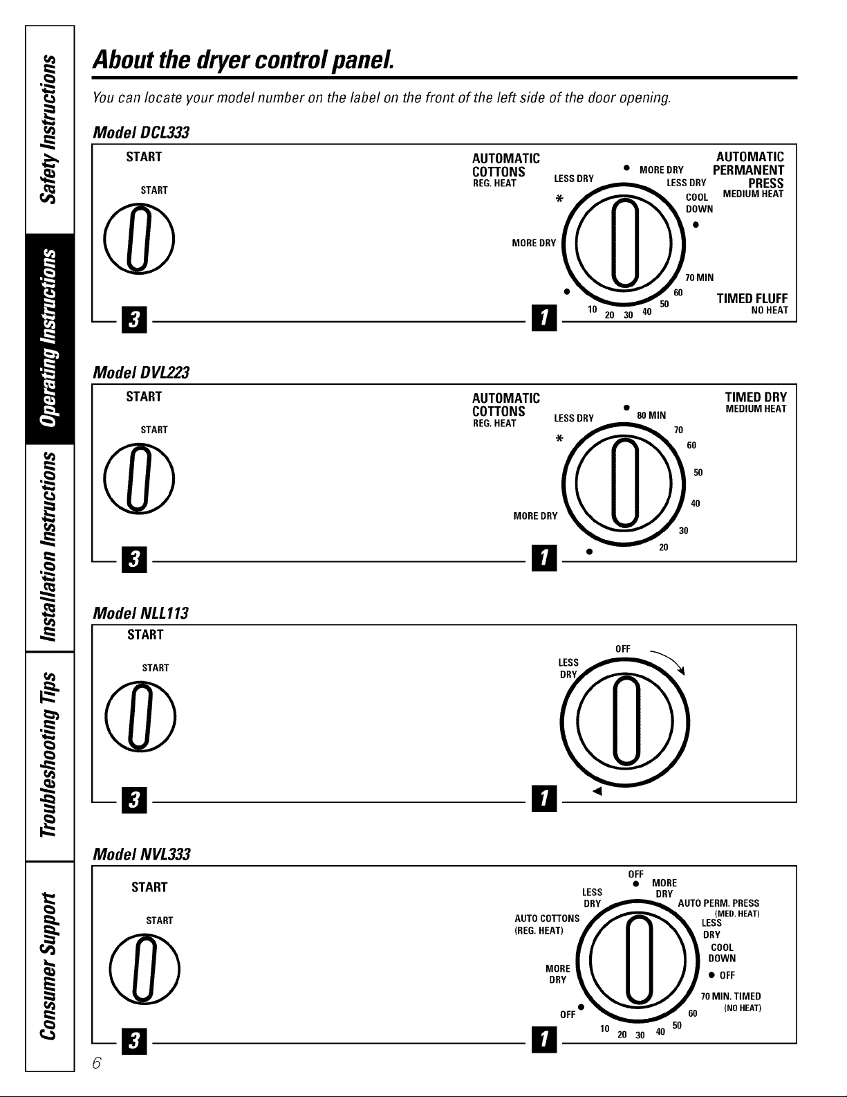
Aboutthe dryercontrolpanel
You can locate your model number on the label on the front of the left side of the door opening.
Model DCL333
START
START
AUTOMATIC AUTOMATIC
COTTONS • MOREDRY PERMANENT
REG.HEAT _LESS DRY PRESS
LESS DRY
,'X..,_"-_"_L COOL
f/! I_'V:=
MEDIUM HEAT
@
Model DVL223
START
START
@
Model NLL113
START
START
oo...._[_,II ))
%_._ZJJ/ 70MIN
• _-""'"_j 60
-- lO_ 50 TIMED FLUFF
H 20 30 40 NOHEAT
AUTOMATIC TIMED DRY
COTTONS • 80 MIN MEDIUM HEAT
REG.HEAT 70_0
LESS DRY
'-X" 6O
5O
40
MOREDRY
• 20
OFF
LESS
@
-El
Model NVL333
START
START
@
8
ii
OFF
LESS DRY
DRY _,= AUTO PERM, PRESS
AUTOCOTTONS f_"_ LES(_ED'HEAT)
• MORE
=EO,HEAT_// I I \\ DR,,
I I I I \ t COOL
I I I I I | DOWN
,_o_\II 21.o,,
% _ %,,l_J" J 70MIN,TIMED
• _ 60 (NOHEAT)
OFF
O 10 20 30 40 50
Page 7
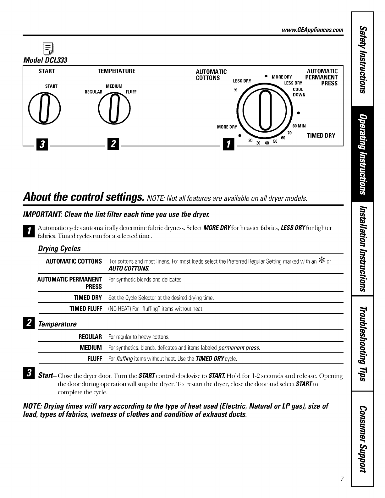
Model DCL333
START TEMPERATURE
www.GEAppliances.com
AUTOMATIC AUTOMATIC
COTTONS • MOREDRY PERMANENT
LESS DRY LESSDRY
DOWN
PRESS
START MEDIUM '-X._
REGUL_UFF COOL
MOREDRY / 00MIN
TIMED DRY
_1_ 20 30 40 50
Aboutthe control
IMPORTANT" Clean the lint filter each time you use the dryer.
_r_ Automatic cycles automatically determine fabric chyness. Select MOREDRYfor heavier fabrics, LESSDRYfbrlighter
fabrics. Timed cycles run fbr a selected time.
Drying Cycles
AUTOMATICCOTTONS Forcottonsandmostlinens.FormostloadsselectthePreferredRegularSettingmarkedwithan :_ or
AUTOMATICPERMANENT Forsyntheticblendsanddelicates.
PRESS
aLlL m_ __
serungs.NOTE: Not all features are available on all dryer models.
AUTOCOTTONS.
TIMEDDRY SettheCycleSelectorat thedesireddryingtime.
TIMEDFLUFF (NOHEAT)For"fluffing"itemswithoutheat.
B Temperature
REGULAR Forregulartoheavycottons.
MEDIUM Forsynthetics,blends,delicatesanditemslabeledpermanentpress.
FLUFF Forfluffingitemswithoutheat.Usethe TIMEDDRYcycle.
_iStart- Close the &yer door. Turn the STARTconu'ol clock_4se to STARTHold tbr 1-2 seconds and release. Opening
the door during operation will stop the &yet. To restm't the &yet, close the door and select STARTto
complete the cycle.
NOTE: Drying times will vary according to the type of heat used (Electric, Natural or LP gas), size of
load, types of fabrics, wetness of clothes and condition of exhaust ducts.
7
Page 8
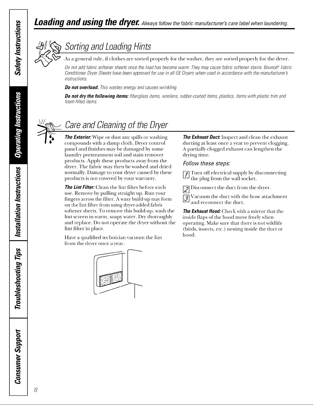
Loadingand usingthe dryer.Always follow the fabric manufacturer's care label when laundering.
SortingandLoadingHints
As a general rule, if clothes are sorted properly for the washer, they are sorted properly for the dryer.
Donotaddfabricsoftenersheetsoncetheloadhasbecomewarm.Theymaycausefabricsoftenerstains.Bounce_ Fabric
ConditionerDryerSheetshavebeenapprovedfor usein a//GEDryerswhenusedinaccordancewith themanufacturer's
instructions.
Do notoverload.Thiswastesenergyandcauseswrinkling.
Do notdrythe following items:fiberglassitems,woolens,rubber-coateditems,plastics,itemswith plastictrimand
foam-filleditems.
\1/.-_.,
CareandCleaningof theDryer
TheExterior:Wipe or dust any spills or washing
compounds with a damp cloth. D_Ter control
panel and finishes may be damaged by some
laun& T pretreatment soil and stain remover
products. Apply these products away from the
duer. The fabric may then be washed and dried
normally. Damage to your dlTer caused by these
products is not covered by your warranty.
The LintFilter: Clean the lint filter beibre each
use. Remove by pulling straight up. Run your
fingers across the filter. A waxy build-up may form
on the lint filter from using due>added fabric
softener sheets. To remove this buil&up, wash the
lint screen in warm, soapy water. DU thoroughly
and replace. Do not operate the dtTer without the
lint filter in place.
Have a qualified technician vacuum the lint
fi'om the dtTer once a year.
TheExhaustDuct:Inspect and clean the exhaust
ducting at least once a year to prevent clogging.
A partially clogged exhaust can lengthen the
dtTing time.
Follow these steps:
Z] Turn off electrical supply by disconnecting
the plug fl'om the wall socket.
[2--]Disconnect the duct from the d_Ter.
[-_ Vacuum the duct with the hose attachment
and reconnect the duct.
TheExhaustHood:Check with a mirror that the
inside flaps of the hood move freely when
operating. Make sure that there is not wildlife
(birds, insects, etc.) nesting inside the duct or
hood.
8
Page 9

FabricCareLabels
WASH LABELS
www.GEAppliances.com
Machine ___
wash
cycle Normal
Water
temperature
BLEACHLABELS
Bleach
symbols
DRY LABELS
Any bleach
(when needed)
U
Permanent Press/
wrinkle resistant
000
Hot
(50°C/120°F)
Only non-chlorine bleach
(when needed)
_U
Gentle!
delicate
O0
Warm
(40°C/105°F)
A
Hand wash Do not wash Do not wring
0
Cold/cool
(30°C/85°F)
Do not bleach
Tumble
dry
Heat_GGO
setting
Special
instructions
Fq
Dry
High Medium Low
Normal Permanent Press/ Gentle/ Do not tumble dry (used with
wrinkle resistant delicate do not wash)
D
Line dry! Drip dry
hang to dry
No heat!air
Dry flat
Do not dry
Pq
Inthe shade
9
Page 10

Prepartingto installyourdryer.
Read these instructions completely and carefully.
WARNING
This dryer must be exhausted to the outdoors
using only rigid metal or flexible metal 4"
diameter ductwork tar inside the dryer cabinet
or exhausting.
• Never useplastic or othercombustibleductwork.
See Exhaustingsection.
• This appliance must be properly grounded
and installed as described in these Installation
Instructions.
• Do not install or store appliance in an area
where it _ill be exposed to water/weather.
See Location of YourOryorsection.
• The National Fuel Gas code resu'icts installations
of gasappliancesin garages. They must be 18"
(45.7 cm) off the ground and protected fl'om
vehicles by a barrier. See Location of Your Dolor
section.
• The electrical serviceto the dryer must conform
with local codes and ordinances and the latest
edition of the National Electrical Code,
ANSI/NFPA 70.
• The gasserviceto the dryer nmst confbrm with
local codes and ordinances or the latest edition
of the National Fuel (;as Code ANSI Z223.1.
The gas dryer is designed under ANSI Z 21.5.1
fbr homeuse only.This d_Ter is not
recommended for commercial applications
such as restaurants or beauty salons, etc.
ToolsandMaterialsRequiredforDryerInstallation
• Phillips head screwdriver
• Channel-lock adjustable pliers
• Carpenter's level
• Flat or su'aight blade screwdriver
• Duct tape
• Rigid or flexible metal 4" (10.2cm) duct
• Vent hood
• Pipe thread sealer (GAS DRYER)
• Plastic knife
• 1/2" open-end wrench
10
UnpackingtheDryer
_] Using the tour shipping carton corner posts
(two on each side), careflflly lay the dryer on
its letY side and remove foam shipping pad.
CAUTION:To prevent damage, do not use
the control panel as a means to pick up or
move the dryer.
[2-_Return the dtTer to an upright position.
I-j] Adjust the leveling legs to match the washer
height. The dxTer must be level and rest firmly
on all four leveling legs.
Page 11
Electrical requirements.
Read these instructions completely and carefully.
ElectricalConnectionInformationforElectricDryers
WARNING--To reduce the risk of fire,
elecu'ic shock, or personal injm7:
• DONOT USEAN EXTENSIONCORDWITH THIS
APPLIANCE.
• THISAPPLIANCEMUSTBE PROPERLYGROUNDED.
Thisdryermustbe electrically groundedin
accordance with local codesandordinances,or in
the absenceof local codes,inaccordancewith the
NATIONALELECTRICALCODE,ANSI/NFPANO.70.
Electrical Requirements
• This dxyer must be connected to an individual
branch circuit, protected by the required time-
delay fllses or circuit breakers. 208V or 240V
installation 30 amps.
• Use copper conductors only.
• If the electric supply does not meet the above
specifications, call a licensed electrician.
NOTE:A wiring diagram is located inside the
control panel.
ElectricalConnectionInformationfor GasDryers
WARNING--To reduce tile risk of fire,
electric shock, or personal injmy:
• DONOT USEAN EXTENSIONCORDORAN
ADAPTERPLUGWITH THISAPPLIANCE.
• DONOT UNDERANYCIRCUMSTANCES,CUTOR
REMOVETHETHIRDGROUNDINGPRONGFROM
THEPOWERCORD.
Thisdryermustbe electrically groundedin
accordance with local codesandordinances,or in
theabsenceof localcodes, in accordancewith the
NATIONALELECTRICALCODE,ANSI/NFPANO.70.
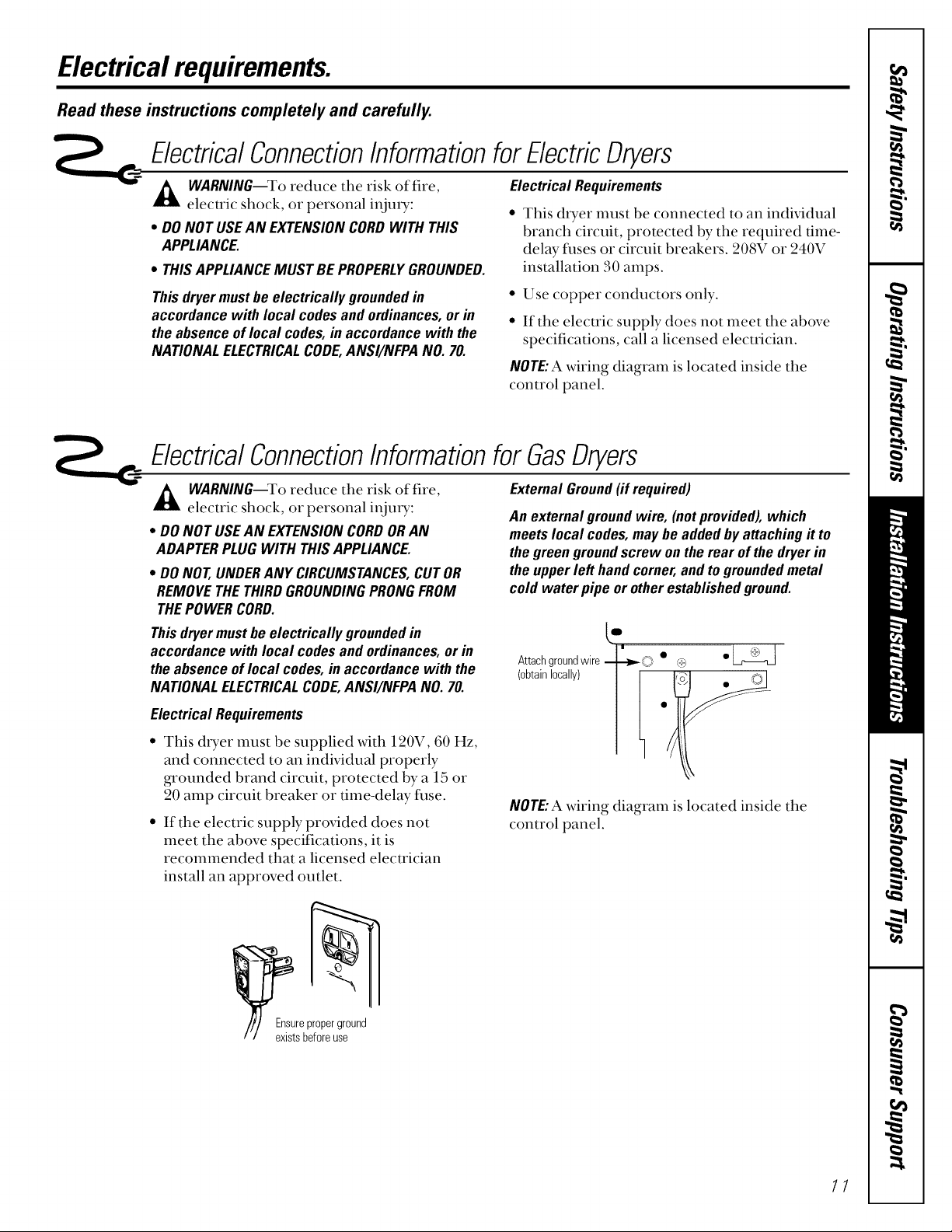
ExternalGround(ifrequired)
An externalgroundwire, (notprovided),which
meetslocal codes,maybe addedby attachingit to
thegreen groundscrew onthe rear of thedryer in
theupperleft handcorner,and togroundedmetal
cold water pipe or otherestablished ground.
Attachgroundwire ,v _+)
........................
Electrical Requirements
This dUeT must be supplied with 120V, 60 Hz,
and connected to an individual properly
grounded brand circuit, protected by a 15 or
20 amp circuit breaker or time-delay fuse.
If the electric supply provided does not
meet the above specifications, it is
recommended that a licensed elecu'ician
install an approved outlet.
Io to, oc l]
NOTE:A wiring diagram is located inside the
control panel.
11
Page 12

Exhausingthedryer.
Read these instructions completely and carefully.
ExhaustSystemRequirements
Useonly4" (10.2cm)diameter(minimum)rigidmetal A
ductforbestperformance,orflexiblemetalduct.Use
approved vent 11oo(!which has swing-out dampers
that open when the dryer is in operation. _qmn the
dryer stops, the dampers automatically close to
prevent drafLs and the entrance of insects and
rodents. To avoid restricting the outlet, maintain a A
mininmm of 12" (. 0.a cm) clearance between the
vent hood and the ,ground or any other obsmmtion.
If all rigid metal duct cannot be used, then flexible
all-metal venting can be used, but it _411reduce the
maximum recommended duct length. See Additional
InstallationInstructionsfollowing.
Do_ Don't
3 -
Correct
Incorrect
ThedryerexhaustsystemMUSTBEEXHAUSTED
AHt
TOTHEOUTSIDEofthedwelling.
DONOTallow combustible materials (for example:
clothing, draperies/curtains, paper) to come in
contact Mth exhaust system.
ThedryerMUSTNOTbeexhaustedintoagasvent,
chimney,a wall, a ceiling,acommonductwith a
kitchenexhaustoranyconcealedspaceofa
buildingwhichcanaccumulatelint,resultingin
a firehazard.
DONOTexceed die lengdl of duct pipe or
A
number of elbows allowed in the MaximumLength
charts. Lint can accumulate in the exhaust
system, plugging the system and creating a fire
hazard, aswell as increasing &)4ng times.
DONOTscreen the exhaust ends of the vent
A
sysmm, nor use aW screws or rivets to assemble
the exhaust system. Lint can become caught in
the screen, on the screws or rivets, clogging the
duct work and creating a fire hazard aswell as
increasing chTing tilnes. Use an approved vent
hood to terminate the duct outdoors, and seal
alljoints with duct tape. All male duct pipe
fittings MUSTbe installed do_lsu'emn with
the flow of air.
12
WARNING:Thefollowingarespecificrequirements
forproperandsafeoperationofyour dryer.Failure
to followtheseinstructionscancreateexcessive
dryingtimes andfirehazards.
DONOTuseplastic flexible duct toexhaust the
dryer.Excessivelintcanbuildupinsideexhaust
systemandcreateafirehazardandrestrictair
flow.Restrictedairflow will increasedryingtimes.
ffFourpresentsystemismadeupofplasticductor
metalfoilduct,replaceitwith rigidorflexible
metalduct.Ensurethepresentductisfreeofany
lintpriortoinstallingdryerduct.
Additional Installation Instructions
If all rigid metal duct cannot be used, then flexible
all-metal venting can be used, but it will reduce the
m>Lximum recommended duct length. In special
installations when it is impossible to make a
connection with the above recommendations, then
UL-listedclothes dryertransitionductmay be used as
mmsition venting between the &yer and wall
connection only. The use of this ducting will affect
&Ting time.
Ifflexibletransitionductisnecessary,onlyUL-listedduct
identifiedforusewith clothesdryersisapproved.
EXPLOSIONHAZARD.Do not install the dtTer
A
where gasoline or odmr flammables are kept
or stored. If the dryer is installed in a garage,
it must be a minimum of 18" (45.7 cm) above
the floor. Failure to do so can result in death,
explosion, fire or bums.
_ rovide an access for inspection and cleaning of
the exhaust system, especially at turns. Inspect
and clean at least once per year.
Do not obsu'uct incoming or exhausted air.
Thefollowingdirectionsmustbe followed.
• Use the shortest length possible.
• Su'etch the duct to its maximum length.
• Do not crash or collapse.
• Never use u'ansition duct inside the wall, flooring,
ceiling or inside the dryer.
• Avoid resting the duct on sharp objects.
• Venting must conibmi to local building codes.
Page 13

Installingthedryer.
Exhaust Ducting Length
The exhaust system should be inspected and cleaned
at least once a year _dth nomml usage. The more the
dUeT is used, the more often you should check the
exhaust system and vent hood for proper operation.
Kroofvents or louvered plenums are used, they must
be equivalent to a 4" dampered wall cap in regard to
resistance to aid]ow, prevention of back drafts and
maintenance required to prevent clogging.
MAXIMUM LENGTH of 4" 110.2cm)Dia. RIGIDMETALDUCT
PREFERREDVENTHOODTYPE
4" 110.2cm) Louvered
• DONOTassemble the duct work with fksteners that
extend into the duct. They will serve as collection
points for lint.
• Ductworkwhich rims through an unheated area or
is near an air conditioning duct should be insulated
to reduce condensation and lint build-up.
MAXIMUM LENGTHof4" 110.2cm)Dia.FLEXIBLEMETALDUCT
PREFERREDVENTHOODTYPE
4" (102 cm) Louvered
Number of
90°turns
0 60' !10.28m)
1 52' (15.04m)
2 44' (13.41m) (9.75m)
3 32' (9.75m) (7.31m)
4 20' (0.53m) (4.87 m)
48' (14.63m)
40' (12.19m)
32'
24'
16'
INSTALL MALE FITTINGSIN
CORRECTDIRECTION
ExhaustDirection
All dryers shipped fi'om fl_efactory are set up for
rear exhausting. However, on ELECTRICDRYERS,
exhausting can be on the right or left side of the
cabinet or the bottom of the dryer. On GAS DRYERS,
exhausting can be on the right side of the cabinet or
the bottom of the dUeT. Directional exhausting can
be accomplished by installing Exhaust Kit, Pub.
No. 14-A018, available through your parts distributor.
Follow the instructions supplied _4th the kit.
Use only rigid metal ducting inside the dryer cabinet.
0
1
2
3 notrecommended
/ Same as EXHAUST DUCT LOCATING
| It" other side DIMENSIONS
(I,_ 5-7/8"
L (15cm) 4-3/8"
3-3/4"(9.5cm)t
30"!9.14m)
22' !6.71m)
14' (4.27m)
_/' 3-I/2" cm)
(34cm)
10' (5.49 m)
14' t4.27m)
10' (3.05m)
gas SupplyRequirements
A Replace brass connecting pipe that is not
plastic-coated. Stainless steel or plastic-coated
brass MUSTbeused.
WARNING:Never reuse old flexible connectors.
The use of old flexible connectors can cm_segas
leaks and personal injury. Alwa}_use NEWflexible
connectors when installing a gas appliance.
Installation MUSTconibrm _dth local codes, or
in the absence of local codes, with the National
Fuel Gas Code, ANSI Z223.1 (latest edition).
The gas supply line should be of 1/2" 11.27 cm)
rigid pipe.
If codes allow, flexible metal tubing may be used
to connectyour dryer to the gas supply line. The
tubing MUSTbeconsu'ucted of stainless steel or
pla_stic-coated brass.
V_]The gas supply line MUSThave an indMdual
shut_ffvalve.
[_-]A 1/8" (0.32 cm) NPT minimum plugged
tapping, accessible for test gauge con_'lection,
MUSTbe installed immediately upstream of the
ga_ssuppb_ connection to the dryer.
V6-]The dryer and its indMdual shutoffvah;e MUST
be disconnected fi'om the gas supply piping
system during aW pressure testing of the gas
supply piping system at test pressures in excess
of 1/2 psig (3.45 kPa).
V_The dryer MUSTbe isolated from the gas supply
piping system by closing its indMdual manual
shutoffvalve during any pressure testing of the
gas supply piping system at test pressures
equal to or less than 1/2 psig (3.45 kPa). 13
Page 14

Installingthedryer.
Read these instructions completely and carefully.
Locationof YourDryer
Do Not Install the Dryer:
p] Donot installthe dryerin an area exposed to
dripping water or outside weather conditions.
]Do not install the &yorin an area where it _s411
come in contact _s4thcurtains, drapes, or
anything that will obstruct the flow of
combustion and ventilation air.
Installation in Recess or Closet
[] ThisdryerMUSTbeexhaustedoutdoors.
f_ No other fuel burning appliance shall be
installed in the same closet as the GAS DRYER.
_] Your dryer needs the space around it for proper
ventilation. DONOTINSTALLYOURDRYERINA
CLOSETWITHASOLIDDOOR
f-_A minimum of 120 square inches (774.2 square
cm) of opening, equally dMded at the top and
bottom of the door, is required. Air openings are
required to be unobstructed when a door is
installed. A louvered door with equivalent air
openings for the fifll length of the door is
acceptable.
[] Do not install the dryer on cmpet.
Floor MUSTbe solid with a maximum slope
of 1" (_2.54cm).
Allow the followingclearancesfor easeofinstallation:
FRONT SIDES REAR TOP
Alcove O(Ocm) O(Ocm) O(Ocm) 15"(38.1cm)
Closet 1"(2.54cm) 0 (0cm) 0(0cm) 15"(38.1cm)
Closet door ventilation required: 2 louvered
openings each 60 square inches (387.1 square cm)
-3" (7.6 cm) fl'om bottom and mp of door.
0
!
|
|
Closetdoor
I
J
!
60 sq. in.
(387.1sq.cm)
sq. in.
(387.1sq.cm)
15"
(38.1cm)
1
0"(0cm)
14
Page 15

Mobile Home Installation
Fff]D1Ter MUSTbe exhausted outside (outdoors, not
beneath the mobile home) using metal ducting
that _411not support combustion. Metal ducting
nmst be 4" (10.16 cm) in dimneter xdth no
obsu'uctions. Rigid metal duct is preferred.
_-_ Ifdxyer is exhausted through the floor, the
exhaust system MUSTNOT'terminate beneath the
mobile home. Termination MUSTbe securely
fastened to the mobile home su'ucture.
f-_ %t_en installing a dxyer into a mobile home,
a provision mt_st be made tbr outside make-up
air. Provide an opening _4th a flee area of at least
25 square inches for inu'oduction of outside air
into the dxyer room.
[-_Gas duets MUSTbe fastened to the floor
using Mobile Home Installation Kit
Pub. No. 14-D346-33.
f_See the ExhaustSystemRequirementssection for
other important venting information.
_-] Installation MUSTconfbrm to current
Manufactured Home Construction & Safeb"
Standard (which is a Federal Regulation Title
24 CFR--Part 32-80) or, when such standard is
not applicable, with American National Standard
fbr Mobile Homes, ANSI/NFPA No. 50lB.
Correct
Incorrect
Don't
Thedryer isdesignedunderANSIZ21.5.1for HOME
USEonly.
flough-lnDimensions
_-_ 267/8" --_,
-- (68.3cm)
471/2"
1
[_ Dooropen
[3-- Electricalconnection
29/16'1_,.
(6.5 cm) I
131/2" -_1
(34.4cm)/
! ©
n-
"_ L._.. 3/8"(O.96cm) Dia.
3 3/4" gaspipe
(9.5cm)
REARVIEW SIDEVIEW
Servicing - Considerationmustbegiven to provide adequate clearances for installation and servicing.
435/8"
(110.7cm)
36"
(91.5cm)
L !
f
1" (2.54cm)
90°
l°
43/8"
(11.1cm)""_!
Optional------_ "
ventknockout .
27" ,_
(68.6cm)
1
m
1
33/4"
(9.5 cm)
CAUTION:Label all wires prior to disconnection when se_icin_ conu'ols. _ iring errors can cause
improper and dangerous operation (verify proper operation after self,icing/installation).
15
Page 16

Installingthedryer.
Read these instructions completely and carefully.
ElectricalInstallationforElectricDryers
A WARNING:Tile fbllo_4ng are specific A WARNING:AUL-approved su'ain relief must be
requirements far proper and safe electrical
installation of your dtTer. Failure to follow
these instructions can create electrical shock
and/or a fire hazard.
A
WARNING: This appliance MUSTbe properly
grounded. Electrical shock can resuh if the
dlyer is not properly grounded. Follow tile
instructions in this manual for proper
grounding.
A
WARNING:DONOTuse an extension cord _dth
this dpyer. Some extension cords are not
designed to _dthstand tile amounts of
electrical current this &yet" utilizes and carl
meh, creating elecuical shock and/or fire
hazard. Locate the duer within reach of the
wall outlet, taking into account the length
of power cord to be purchased and allowing
some slack in the cord. Refer to Electrical
Requirements in this manual for the proper
power cord to be purchased.
installed onto power cord. If the strain relief is
not attached, tile cord can be pulled out of the
dpyer and can be cut by any movement of the
cord, resulting in electrical shock.
A WARNIN& Usecopperreceptaclesonly.
NOTE:Dlyers operating on 208-voh power supply will
have longer d*ying times than those operating on
240-voh power supply.
A wiring diagram is located inside fire conu'ol panel.
Grounding Requirements
A DANGER:Improperconnectionofthe
equipment-_'ounding conductor can result in a risk
of electric shock. Check with a licensed elecu'ician if
you are in doubt a_sto whether the appliance is
properly grounded.
Grounding must be in accordance with local codes
and ordinances, or in the absence of local codes, in
accordance _4th the National Elecuical Code
ANSI/NFPA No. 70.
Foragrounded,cord-connectedelectricdryer:
I-]]Tile &yer MUSTbe grounded. In the event of
a malfimction or breakdown, _'ounding will
reduce the risk of electrical shock by creating
a path of least resistance fbr electrical current.
[_ If your duer is equipped with a power supply
cord having an equipment-_'ounding conductor
and a grounding plug, tile plug MUSTbe plugged
into an appropriate, copper-wired receptacle that
is properly installed and grounded in accordance
with all local codes and ordinances. Ifin doubt, call
a licensedelectrician.
Forapermanently-connectedelectricdryer:
• The &Ter MUSTbe connected to a grounded
metal, permanent wMng system; or an equipment-
grounding conductor must be run _4th the circuit
conductors and connected to the equipment-
grounding terminal or lead on the appliance.
Foracord-connectedgasdryer:
• This &Ter is equipped with a three-prong
(grounding) plug for your protection against
shock hazard and should be plugged directly into
a properly grounded three-prong receptacle.
Do not cut or remove the grounding prong fl'om
this plug.
16
Page 17

3-Wire System for Electric Dryers-DO NOT use for Mobile Home Installations
_] Remove the screws securing the temfinal block
access cover and the strain relief mounting
bracket located on the back of the duer
upper corner.
[2-_Install a UL-approved su'ain relief into the power
cord entry"hole of the mounting bracket. Use
a su'ain relief which attaches to the mounting
bracket with a nut. Finger-tighten the nut only
at this time.
Vj] Thread a UL-approved 30A, 240V, 3 #10 AWG
minimum copper conductor power cord through
the strain relief.
Green gl
Green neutral
gr°undwire _//__ _/"(\Nu_
Use copper Strain elief Po_wercord
Silverterminal
_/'/"'%lighten nut to
thesethreads
conductorsonly. mountingbracket
V_ Attach the power cord neuu'al (center _4re)
conductor to the silver-colored center terminal
on the terminal block. Tighten the screw
securely.
_] Attach the remaining two power cord outer
conductors to the ol{ter brass-colored temnnals
on the terminal block. Tighten both screws
securely.
WARIVING:Donot make a sharp bend or crimp
wiring/conductor at connections.
_-] Reattach the su'ain relief mounting bracket to
the back of the dryer _4th two screws" Tighten
screws securely.
[--_Tighten the f_steners securing the cord restraint
firl'nly against the power cor&
[_ Tighten the strain relief nut securely so that the
strain relief does not turn.
V_ Reinstall the temnnal block access cover.
4-Wire System for Electric Dryers--MUST be used for Mobile Home Installations
[7] emove the screws securing the temfinal block
access cover and the strain relief mounting
bracket located on the back of tim dtTer
upper corner.
[_-]Install a UL-approved smtin relief in the enuy
hole of the mounting bracket. Use a strain relief
which attaches to the mounting bracket with a
nut. Finger-tighten the nut only at this time.
V_]Remove the green neutral _'ound _4re from
the _een _ound screw located at)ove the
temfinal block.
Typical4
conductor| | | ]
receptacle_J
Typical
4conductorcord_
Black240V
,_- Whiteneutral
_,_ Red240V
" Greenground
V_ Thread a UL-approved 30A, 240V, 4 #10 AWG
minimum copper conductor power cord fllrough
the strain relief.
_ ttach the _een power cord ground wire to the
cabinet with the _'een _'ound screw.
_-] Attach the white (neuu'al) power cord conductor
fi'om the power cord and the green ground _4re
V-_ Attach the red and black power cord conductors
to the outer bra_ss-colored terminals on the
temfinal block.
Greenground _ /
screw Silverterminal
Greenneutral _ __'_,
groundwire mJ_,_)'S/_i_ --'_'_ Black
Red!,,,,,,____['/_White / Nut lighten nutto
Powercord/ _ [nounting[_)_ "_
Green power cord ground wire
_'__'_J_ _._Terminal block
_!_ _, _i¢'_ these threads
//..,. ,J/// Strain_._
'/'_" _ relief T .Y"/_&
bracket
WARNING:Donot make a sharp bend or crimp
wiring/conductor at the connections.
_-] Tighten the fasteners securing the cord
restraint firmly against the p[)wer cord.
_-_ Tighten the strain relief nut securely so the strain
relief does not tuna.
-0]Reinstall the terminal block access cover.
fi'om the dryer harness to the silver-colored
center terminal on the terminal block. Tighten
the screw securely.
17
Page 18

Installingthedryer.
Read these instructions completely and carefully.
GasConnectionforGasDryers
[-_ Rentove the shipping cap from gas pipe at tile
rear of tile dtTer.
NOTE:DONOTconnect tile dryer m LP gas setx_ce
without converting tile gas valve. An LP conversion
kit (Pub. No. 14-A038) MUSTbe installed bya
qualified gas technician.
[] Connect a 1/2" (1.27 cm) I.D. semi-rigid
or approved pipe from gas supply line to
the 3/8" (0.96 cm) pipe located on the back
of the dryer. Use a 1/2" to 3/8" (1.27 cmm
0.96 cm) reducer for a connection. Apply an
approved thread sealer that is resistant m the
CO1TOSiveaction of liquefied gases on all pipe
connections.
BeforeOperatingtheDryer
Connect the exhaust duct to outside exhaust
system. Use duct tape to seal all joints.
[2-_With the dryer in its final position, adjust one or
more of the legs until tim dryer is resting solidly
on all fbur legs. Place a level on top of the dryer.
THEDRYERMUSTBELEVELANDRESTING
SOLIDLYONALLFOURLEGS.Turn tile lock nuts
on each of the fbur legs up toward tile base of the
dryer and snug with a 1/2" open-end _u'ench.
I-j] Plug the power cord into a grounded oudet.
NOTE:Cl{eck to ensure the })ower is offat circuit
breaker/fuse box befbre plugging the power
cord into tile outlet.
[_ Turn on the at the circuit breaker/
fuse box.
power
I-j] Open the shutoffvalve in the gas supply line.
[-_ Test all connections by brushing on a soapy water
solution.
CAUTION:NEVERTESTFORGASLEAKSWITH
AN OPENFLAME.
NOTE:On gas dryers, before the burner will light,
it is necessary fbr the gas line to be bled of air. If
the burner does not light within 45 seconds the first
time the dryer is turned on, the safety switch will
shut the burner off. If this happens, mm the timer
m OFFandwait 5 minutes before making another
attempt m light.
CAUTION:Before operating tim dryer, make
sure the dryer area is clear and flee front
combustible materials, gasoline, and other
flmmnable vapors. Also see that nothing
(such as boxes, clothing, etc.) obstructs the
flow of combustion and ventilation air.
_-]Run the dryer through a cycle check for proper
operation.
[-6-]If your dryer does not operate, please review the
TroubleshootingTips section in this manual befbre
calling fbr set-dce.
_-] Place these instructions in a location near the
dryer for future reference.
18
Page 19
ReplacementParts
If replacement par_s are needed for your dryer,
contact the source where you purchased your duer.
CAUTION:Label all _dres prior to disconnection
A
when servicing conu'ols. Wiring errors can
cause improper and dangerous operation.
Veriff proper operation after set_"icing.
WARNING:Destroy the carton and plastic bags
A
after the dryer isunpacked. Children might use
them/or pl W. Cartons covered _"ith rags,
bedspreads or plastic sheets can become
airtight chambers causing suffocation. Place all
materials in a garbage container or make
materials inaccessible to children.
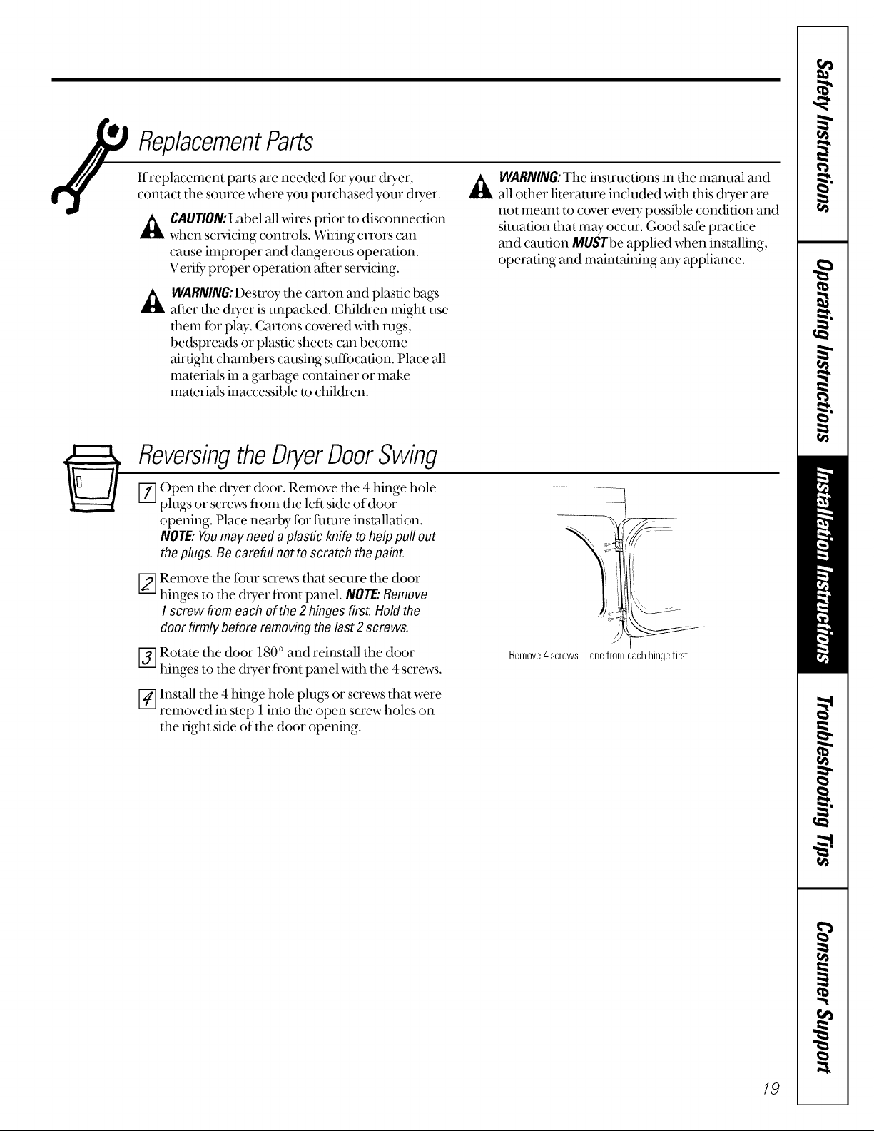
ReversingtheDryerDoorSwing
F_] Open the dryer door. Remove the 4 hinge hole
plugs or screws fl'om the left side of door
opening. Place nearby tbr filmre installation.
NOTE:Youmayneedaplastic knife to helppullout
theplugs.Be careful notto scratch the paint.
F2-]Remove the ibm" screws that secure the door
hinges to the dryer front panel. NOTE."Remove
I screw fromeach of the2 hinges first.Holdthe
door firmlybeforeremovingthelast2 screws.
,_WARNING: The instructions in the manual and
all other literature included _dth this duet are
not meant to cover eve U possible condition and
situation that may occur. Good s_e practice
and caution MUSTbe applied when installing,
operating and maintaining any appliance.
_] Rotate the door 180° and reinstall the door
hinges to the dryer front panel with the 4 screws.
[-_ Install the 4 hinge hole plugs or screws that were
removed in step 1 into the open screw holes on
the right side of the door opening.
Remove4screws--onefromeachhingefirst
19
Page 20

Beforeyoucall forservice...
Troubleshooting tips
Save time and money! Review the charts on the following
pages first and you may not need to call for service.
Problem Possible Causes What ToDo
Drier doesn'tstatt Dryer is unplugged * Make sure the chyer plug is pushed completely into
Fuse is blown/circuit breaker * Check the household Disu'ibution Panel iilse/circuit
is tripped breaker box in your home, and replace fuse or reset
Thermal limiter tripped * Call authorized service person for replacement.
Drier doesn't heat Fuse is blown/circuit breaker * Check the fuse/circuit breaker box in yore" home, and
is tripped, the dryer may replace iilse or reset breaker.
tumble but not heat
Gas service is off * Make sure gas shutoffat &yer and main shutoffare
There are 2 fuses in the • Replace ihse.
household Distribution Panel
for the dryer circuit. If 1 of the
2 fuses in the household
Distribution Panel is blown,
the drum may turn but the heat
will not operate
the outlet.
breaker. NOTE:Most elecu'ic dryers require your home
to use 2 fuses or a breaker.
fiflly open.
Gas supply valve is not open * Check to make sure supply valve is open.
(gas models) See InstallationInstructionsibr procedure.
Dryer does not have enough air • See Installation Instructions
supply to support the burner
flame (gas models)
LP gas supply tank is empty * Refill or replace tank. D_yer should heat when utility
or there has been a utility service is restored.
interruption of natural gas
(gas models)
Drier shakes or Some shaking/noise is normal. * Move &yer to an even floor space, or adjust leveling legs
makes noise Dryer may be sitting unevenly as necessmy until even.
Greasy spots on clothes Improper use of labile softener * Follow directions on fabric softener package.
Drying dirty items with • Use your duer to dU only clean items. Dirty"items can
clean ones stain clean items and the duet.
Clothes were not * Sometimes stains which cannot be seen when the clothes
completely clean are wet appear after duing. Use proper washing
procedures before drying.
Linton clothes Lint filter is full • Clean lint screen before each load.
Improper sorting * Sort lint producers (like chenille) from lint collectors
(like corduroy).
Static electricity can attract lint • See suggestions in this section under STATIC.
Overloading • Sepatvtte large loads into smaller ones.
Paper, tissue, etc. left in pockets * Empty all pockets before laundering clothes.
2O
Page 21

www.GEAppliances.com
Problem Possible Causes
Static occurs No fabric softener was used
Overdrying • T_y a iabfic soi_ener.
Synthetics, permanent press • T*y a ihbfic soi_ener.
and blends can cause static
Inconsistent Type of heat • Automatic dD_ng times will valy according to the t3qoe
drying times of heat used (elecu'ic, natural or LP ga_s), size of load,
Clothes take Improper sorting • Separate heax T items fl'om lightweight items (generally,
too long to dry a well-sorted washer load is a welbsorted &yet load).
Large loads of heavy fabrics • Large, heax T fabrics contain more moisture and take
(like beach towels) longer to dU. Separate large, heax T fabrics into smaller
Controls improperly set • Match conu'ol settings to the load you are duing.
Lint Filter is full • Clean lint filter befbre eve U load.
Improper or obstructed dueling • Check installation insu'uctions fbr proper
What ToDo
* Try a fabric softener.
• Bounce ®Fabric Conditioner Dlyer Sheets have been
approved fbr use in all GE Duers when used in
accordance _th the manufacturer's insu'uctions.
• Adjust controls for less &ying.
t}_es of fabrics, wemess of clothes and condition of
exhaust ducts.
loads to speed dly_ng time.
ducting/venting.
• Make sure ducting is clean, ii'ee of kinks and
unobstructed.
• Check to see if outside wall damper operates easily.
• Check the Installation Insu'uctions m make sure the
d*yer venting is correct.
Blown fuses or tripped • Replace filses or reset circuit breakers. Since most duets
circuit breaker use 2 ruses/breakers, make sure both are operating.
Overloading/combining loads • Do not put more than one washer load in the duer
at a time.
Underloading • If you are drying only one or two items, add a iew items
to ensure proper rambling.
Clothes are wrinkled Overdrying • Select a shorter &ying time.
• Remove items while they- still hold a slight amount of
moisture.
Letting items sit in dryer • Remove items when ©'cle ends and fold or hang
after cycle ends immediately.
Clothes shrink Some fabrics will nattwally shrink • To avoid shrinkage, itllow gammnt care labels exactly.
when washed. Others can be • Some items may be pressed back into shape after drying.
safelywashed, but will shrink
in the dryer • If you are concerned about shrinkage in a particular
item, do not machine wa_shor ramble d_yit.
27
Page 22

m
__ Notes.
m
m
w
m
m
m
1=
w
m
w
_ L
22
Page 23

GEDryer Warranty.
All warranty service provided by our Factory Service Centers,
or an authorized Customer Care®technician. Toschedule service,
on-line, 24 hours aday, vis# us at www.GEAppliances.com,
or call 800.GECARES(800.432.2737).
For The Period Of: GE Will Replace:
One}'ear
Fromthedateof the
originalpurchase
What GE Will Not Cover:
• Service trips to your home to teach you how to use the
product.
• Improper installation.
• Failure of the product if it is abused, misused, or used for
other than the intended purpose or used commercially.
This warranty is extended to the original purchaser and any succeeding owner for products purchased for home
use within the USA. In Alaska, the warranty excludes the cost of shipping or service calls to your home.
Anypartof the chyer which fails due to a defect in materials or worlananship. During this
full one-year warranty, GE will also provide, free ofcharge, all labor and in-home setx_iceto
replace the defective parc
• Replacement of house ['uses or resetting of circuit
breakers.
• Damage to the product caused by accident, fire, floods or
acts of God.
• Incidental or consequential damage caused by possible
defects with this appliance.
Staple your receipt here.
Proof of the original purchase
date is needed to obtain service
under the warranty.
Some states do not allow the exclusion or limitation of incidental or consequential damages. This warranty gives
you specific legal rights, and you may also have other rights which vary from state to state. To know what your
legal rights are, consult your local or state consumer affairs office or your state's Attorney General
Warrantor: General Electric Company.Louisville, KY 40225
23
Page 24

ConsumerSupport.
GEAppliancesWebsite wvvvv.GEAppliances.com
Have a question or need assistance with your appliance? T_y the GE Appliances Website 24 hours a day,
aW day of the year! For ,greater convenience and faster sewice, you can now download Owner's Manuals,
order parts, catalogs, or even schedule selMce on-line. You can also "Ask Our Team of Experts rv''
your questions, and so much more...
ScheduleService
Expert GE repair service is only one step mvayfrom your door. Get on-line and schedule your sewice at
your convenience 24 hours any day of the year! Or call 800.GE.CARES (800.432.2737) during normal
business hours.
RealLifeDesignStudio
GE supports the Universal Design concept-products, services and environments that can be used by
N
people of all ages, sizes and capabilities. We recognize the need to desi_l tot a wide range of physical and
mental abilities and impairments. For details of (;E's Universal Desi_l applications, including kitchen
design ideas tot people with disabilities, check out our Website today. For the hearing impaired, please call
800.TDD.GEAC (800.833.4322).
ExtendedWarranties
Purchase a GE extended warranty and learn about special discounts that are mTailablewhile your wan'an_ _
is still in effect. You can purchase it on-line anytime, or call 800.626.2224 during normal business hours.
GE Consumer Home Smvices will still be there after your wan'anty expires.
PartsandAccessories
wvvvv.GEAppliances.com
wvvvv.GEAppliances.com
wvvvv.GEAppliances.com
wvvvv.GEAppliances.com
IndMduals qualified to sets,ice their own appliances can have parts or accessories sent directly to their homes
(VISA, MasterCard and Discover cards are accepted). Order on-line today, 24 hours every day or by phone at
800.626.2002 during nomml business hours.
Instructionscontainedinthismanualcoverprocedurestobe performedbyanyuser.Otherservicing generally
shouldbe referredto qualifiedservicepersonnelCautionmustbeexercised,sinceimproperservicingmaycause
unsafeoperation.
ContactUs
Ifyou are not satisfied _4th the service you receive front GE, contact us on our Website with all the details
including your phone number, or write to: General Manager, Customer Relations
GE Appliances, Appliance Park
Louisville, KY 40225
vvvvvv.GEAppliances.com
RegisterYourApplbnce wvvvv.GEAppliances.com
Register your new appliance on-line--at your convenience! Timely product registration will allow for
enhanced communication and prompt set_4ce under the temps of your wan'anty, should the need arise.
You may also mail in the pre-printed regisu'ation card included in the packing material, or detach and
use the torm in this ()_mr's Manual.
Printed in the United States
 Loading...