

GE DCCB330GG3WC, DCCB330GG4WC, DCCB330GG5WC, DCCB330GJ0WC, DCCD330GG4WC Installation Guide
...Page 1
Installation GasDryeri
nstructions I 45 l@
If yours is a coin operated dryer:
a. Post in a prominent location instructions to be followed in
the event the user smells gas. The intbrmation to be posted
shall be obtained by consulting with the local gas supplier.
b. Post this caution in a prominent location.
BEFOREYOU BEGIN
Read these instructions completely and carefully"
• IMPORTANT -s_,,_these
instructions for local inspector's use.
• IMPORTANT -,:'bser,eaII
,( - "_,- codes and ordinances.
,% )_v el 1]tl
• Note to Installer Be sure to leave these instructions with
tile custoIner
• Note to Customer - Keep these instructions with yore: tse
and Care Book fl_r f:utttre retk_rence.
• This dryer must be exhausted to the outdoors.
• Betbre ihe old dryer is removed from service or discarded,
remove the dryer" door
• Service Information and the wiring diagram are located in
the control console.
• Service of this dryer must be performed by a qualified
installer, service agency, or the gas supplier.
• Do not allow children on or in the appliance. Close
supervision of children is necessary when the appliance is
used near children.
i i ,
FORYOUR SAFETY !1
Do not store or use gasoline or other flammable
vapors and liquids in the vicinity of this or any
other appliance.
ii ii i
FORYOUR SAFETY:
_, WARNING
• [se o _lv rioid metal or flexible metal _-in. diameter
ductwork for exhausting to the outdoors. Ne_er use
plastic or other combustible easy to-puncture ductwork.
" This appliance must be properly gTounded and installed
as describe(] in these instructions.
• Do not install or store appliance in an area where it
will be exposed to water and/or weather:
• The National Fuel Gas Code restricts installations of
gas appliances in garages. They nmst be 18 in. off the
ground and protected by a barrier from vehicles.
• Install the dryer where the temperature is above 50°F
lot satisfactory operation of the dryer control system.
n u I
In the state of Massachusetts
Installation must be performed by a qualified or
licensed contractor, plumber, or gasfitter qualified or
licensed by the state.
al
{I
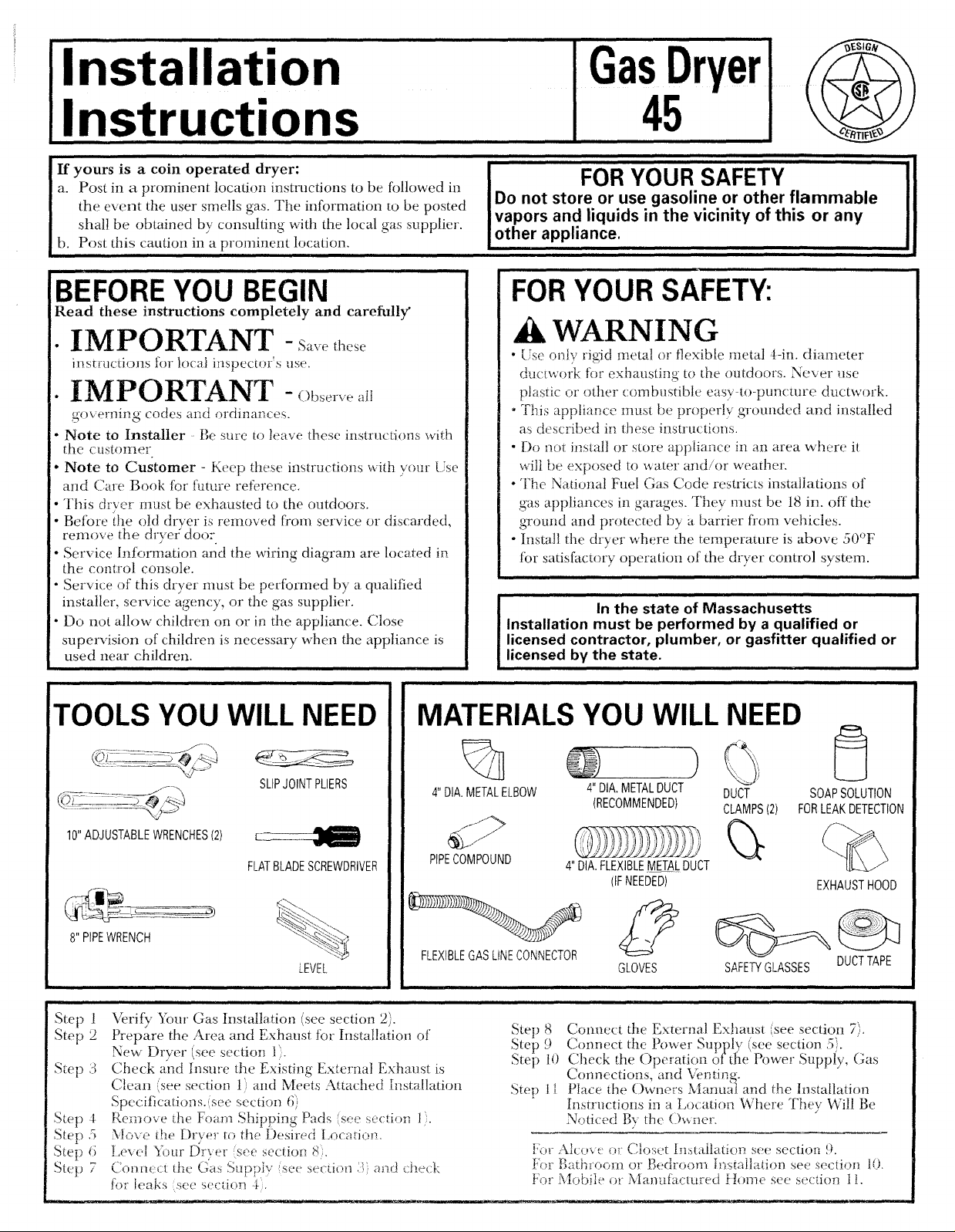
TOOLS YOU WILL NEED
SLIPJOINTPLIERS
10"ADJUSTABLEWRENCHES(2)
FLATBLADESCREWDRIVER
_.'_,.
_.
8" PIPEWRENCH
LEVEL
,lll l
Step !
Step 2
Step 3
Step 4
Step 5
Step ti
Step 7 (onm:_:ltEeGas" _ " ' .....
Verify Your Gas Installation (see section 2).
Prepare the Area and Exhaust tbr Installation of
New' Dryer (see section 1).
Check and Insure tile Existing External Exhaust is
Clean (see section 1) and Meets Attached Installation
Specifications.(see section 6)
Rem,_ve the Foam Shipping Pads (so,,, see*don 1).
Move the Dryer to the Desired kocatio!>
[,e_ el _)ur 15r_er (see section 8}.
_>u[piy se< section::' andche(k
for leaks see s_'ction 4:,
MATERIALSYOU WILL NEED
%
4"DIA.METALELBOW
4" DIA.METALDUCT DUCT
(RECOMMENDED) CLAMPS(2)
)
Of-
PIPECOMPOUND
FLEXIBLEGASLiNECONNECTOR
Step 8 Connect the External Exhaust (see section 7).
Step9 " _ " _" - "" -" '
Step t i) Check the Operation ottl:{e Power Suppl'y, (;as
Step 1I Place the ()whets Manual and the Installation
4" DIA.FLEXIBLEMETALDUCT
(IFNEEDED)
GLOVES
Connect the ! ovver 5upplx. ksee sectum .),.
Connections and Venti_ ,-
Insiructions in a t,ocation Where They Will Be
Nt__ticedB? the ()_ler.
Fo_ :\icoxe or Closet [nstaitati(m see section 9.
For Bathroom or Bedroom b'_,4ailation see s_:ction t0.
For Mobile _)_ Mantfl'acmred }[ome see secticm 11.
SAFET"/GLASSESDUCTTAPE
I
SOAPSOLUTION
FORLEAKDETECTION
EXHAUSTHOOD
Page 2
i| I IIN I II IN
Installation Instructions
Minimum clearance to combustible surfaces and for air opening are: 0 in. clearance both sides and ! in. rear. Consideration
must be Nven to provide adequate clearance for proper operation and service.
i II HU. I N. I Iml. I III I .
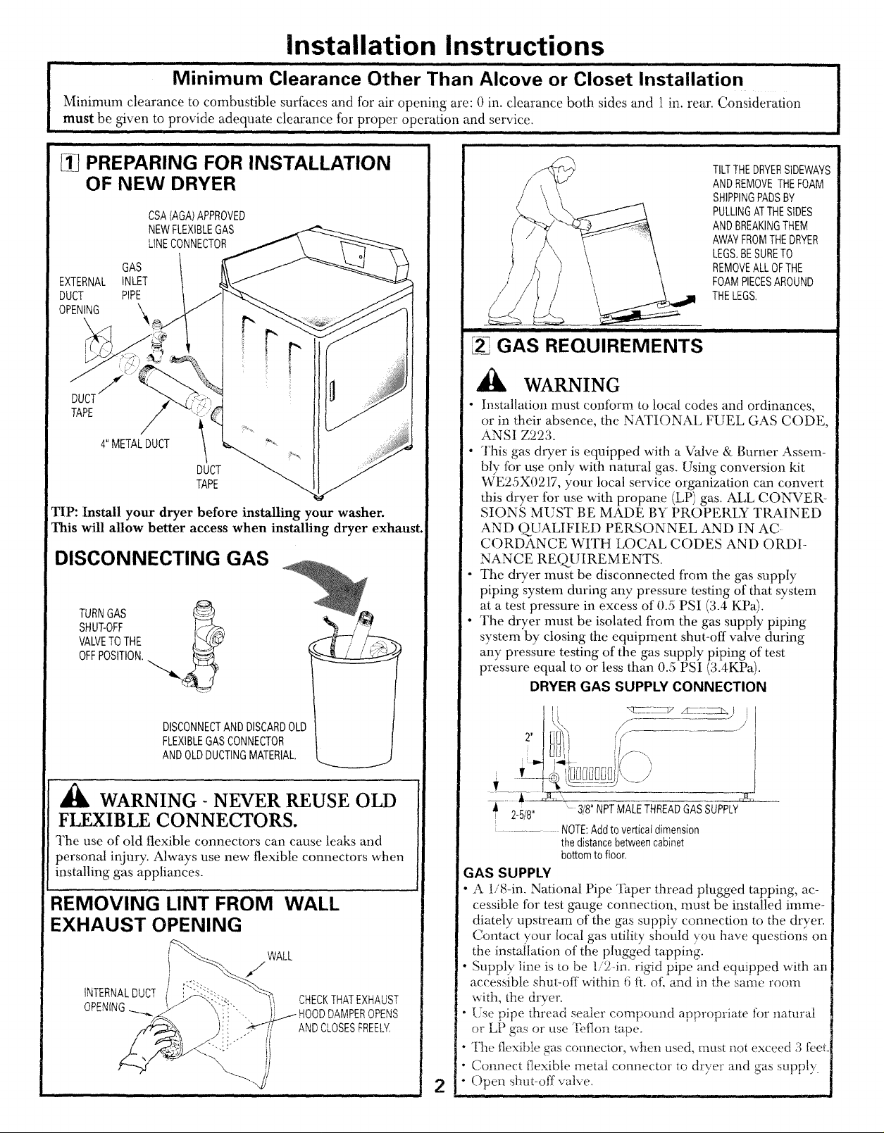
[_ PREPARING FOR INSTALLATION
OF NEW DRYER
GAS
EXTERNAL INLET
DUCT PIPE
OPENING '_
Minimum Clearance Other Than Alcove or Closet Installation
II I I
/
CSA(AGA)APPROVED
NEWFLEXIBLEGAS
LINECONNECTOR
i iii ii i i
iii
,, i i i
TILTTHEDRYERSIDEWAYS
ANDREMOVETHEFOAM
SHIPPINGPADSBY
PULLINGATTHESIDES
ANDBREAKINGTHEM
AWAYFROMTHEDRYER
LEGS.BESURETO
REMOVEALLOFTHE
FOAMPIECESAROUND
THELEGS,
GAS REQUIREMENTS
WARNING
TAPE
4" METALDUCT
DUCT
TAPE
TIP: Install your dryer before installing your washer.
This will allow better access when installing dryer exhaust.
DISCONNECTING GAS
TURNGAS
SHUT-OFF
VALVETOTHE
OFFPOSITION.
• Installation must conform to local codes and ordinances,
or in their absence, the NATIONAl, FUEL GAS CODE,
ANSI Z223.
• This gas dryer is equipped with a Valve & Burner Assem-
bly for use only with natural gas. Using conversion kit
WE25X0217, your local service organization can convert
this dryer for use with propane (LP) gas. ALL CONVER-
SIONS MUST BE MADE BY PROPERLY TRAINED
AND QUALIFIED PERSONNEL AND IN AC-
CORDANCE WITH LOCAL CODES AND ORDI-
NANCE REQUIREMENTS.
• The dryer must be disconnected from the gas supply
piping system during any pressure testing of that system
at a test pressure in excess of 0.5 PSI (3.4 KPa).
• The dryer nrust be isolated from the gas supply piping
system by closing the equipment shut-off valve during
any pressure testing of the gas supply piping of test
pressure equal to or less than 0.5 PSI (3.4KPa).
DRYER GAS SUPPLY CONNECTION
DISCONNECTANDDISCARDOLD
FLEXIBLEGASCONNECTOR
ANDOLDDUCTINGMATERIAL.
WARNING- NEVER REUSE OLD
FLEXIBLE CONNECTORS.
The use of old flexible connectors can cause leaks and
personal injury. Always use new flexible cormectors when
installing gas appliances.
REMOVING LINT FROM WALL
EXHAUST OPENING
WALL
CHECKTHATEXHAUST
DAMPEROPENS
ANDCLOSESFREELY,
I 3,, ,f-- -- ./
t[3i/
f
! {li i!/---.
7__
2-5/8" -3/8" NPTMALETHREADGASSUPPLY
....... NOTE:Addtoverticaldimension
thedistancebetweencabinet
bottomtofloor.
GAS SUPPLY
" A !/8-in. National Pipe Taper thread plugged tapping, ac-
cessible for test gauge connection, must be installed imme-
diately upstream of the gas supply connection to the dryer.
Contact your local gas utility should you have questions on
the instailation of the plugged tapping.
• Supply line is to be 1/24n. rigid pipe and equipped with an
accessible shut-off within 6 fL of\ and in the same room
with, the drver.
Ese pipe thlead sealer compound appropriate for natural
or LP gas or use -[bflon tape.
" The flexible gas connector, _&en used, must not exceed 3 feet.
• Connect flexible metal connector to dryer and gas supply.
• Open shut-off vane.
2
Page 3
i, i i
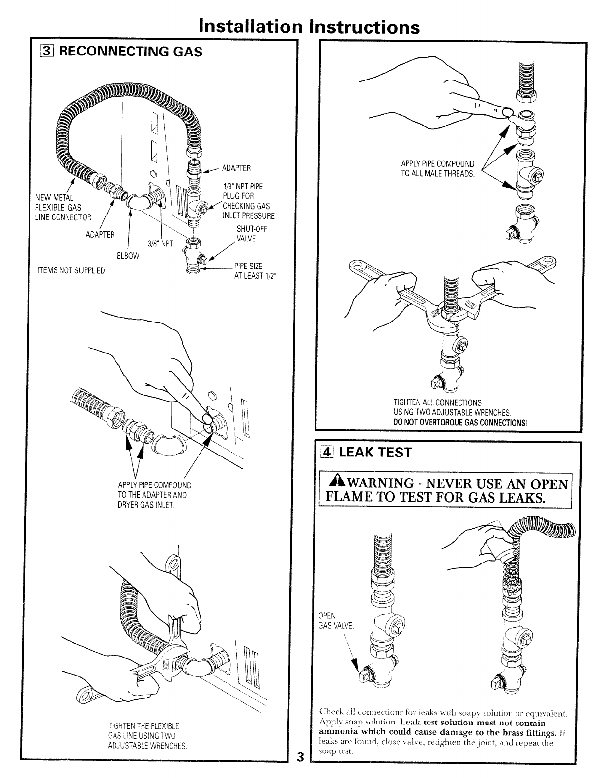
RECONNECTING GAS
Installation Instructions
!
NEWMETAL
FLEXIBLEGAS
LINECONNECTOR
ADAPTER
ITEMSNOTSUPPLIED
ELBOW
ADAPTER
1/8"NPTPIPE
PLUGFOR
INLETPRESSURE
SHUT-OFF
VALVE
f
PIPESIZE
ATLEAST1/2"
APPLYPIPECOMPOUND
TOALLMALETHREADS.
TIGHTENALLCONNECTIONS
USINGTWOADJUSTABLEWRENCHES.
DONOTOVERTORQUEGASCONNECTIONS!
APPLYPIPECOMPOUND
TOTHEADAPTERAND
DRYERGASINLET,
TIGHTENTHEFLEXIBLE
GASLINEUSINGf'l/VO
ADJUSTABLEWRENCHES.
LEAK TEST
[ ,_kWARNING - NEVER USE AN OPEN
FLAME TO TEST FOR GAS LEAKS.
OPEN _I
GASVALVE, _
Check al! connections for leaks with soapy ,_;oludcmor equivalent.
Apply soap solution. Leak test solution must not contain
ammooia which could cause damage to the brass fittings, If
leaks are found, close v'a!_e, ret:igh_e_) the,joint, and repea( the
,soap test.
3
i i ,i
Page 4

Installation Instructions
i
ELECTRICAL CONNECTION
INFORMATION
,_ WARNING- TO REDUCE THE RISK OF
FIRE, ELECrRICAL SHOCK, AND PERSONAL
INJURY:
• DO NOT USE AN EXTENSION CORD OR AN
ADAPTER PLUG WITH THIS APPLIANCE.
Dryer must be electrically grounded in accordance with
local codes and ordinances, or in the absence of local
codes, in accordance with the NATIONAI, ELECTRI-
CAL CODE, ANSIiNFPA NO. 70.
ELECTRICAL REQUIREMENTS
This appliance nmst be supplied with 120V, 60Hz, and connected
to a properly grounded branch circuit, protected by a 15- or 20-
amp circuit breaker or time-delay tuse. If eleclricat supply provid
ed does not meet the above specifications, it is recommended that
a licensed electrician install an approved outlet.
WARNING - THIS DRYER IS EQUIPPED
A THREE-PRONG (GROUNDING) PLUG FOR
YOUR PROTECTION AGAINST SHOCK
HAZARD AND SHOULD BE PLUGGED
DIRECTLY INTO A PROPERLY GROUNDED
THREE-PRONG RECEPTACLE. DO NOT CUT
OR REMOVE THE GROUNDING PRONG
FROM THIS PLUG.
,.|=
EXHAUST INFORMATION
,_ WARNING- USE ONLY METAL 4-IN. DUCT.
DO NOT USE DUCT LONGER THAN SPECIFIED
IN THE EXHAUST LENGTH TABLE.
Exhaust longer than specified wilt:
• Increase the drying times and the energy cost.
• Reduce the dryer life.
• Accumulate lint, creating a potential fire hazard.
The correct exhaust installation is your responsibility.
Problems due to incorrect installation are not covered
by the warranty.
The MAXIMUM ALLOWABLE length of the exhaust system
depends upon the type of duct, number of turns, the type of
exhaust hood (wall cap), and all conditions noted below. Boih
rigid and flexible metal duct are shown in the table below.
EXHAUST LENGTH
RECOMMENDED MAXIMUM LENGTH
Exhaust Hood Types
Recommended
€ -4;
"_] 4" i"4--
No. of 90° Rigid Flexible
Elbows Metal Metal
0 90 Feet 55 Feet
t 60 Feet 40 Feet
2 45 Feet 30 Feet
3 35 Feet 20 Feet
If using flexible metal duct, please refer to page 6,
Use only for short
run installations
4" DIA.
]IL/
...._ "4--2-1/2"
Rigid Flexible
Metal Metal
60 Feet 45 Feet
45 Feet 30 Feet
35 Feet 20 Feet
25 Feet ....t5 Feet
ENSURE PROPER GROUND EXISTS BEFORE USE.
IFLOCALCODESPERMIT,
ANEXTERNALGROUNDWIRE
(NOTPROVIDED),WHICHMEETS
LOCALCODES,MAYBEADDED
BYATTACHINGTOTHEGREEN
GROUNDSCREWONTHEREAR
OFTHEDRYER,ANDTOAGROUNDED
METALCOLDWATERPIPEOROTHER
ESTABLISHEDGROUND.
EXHAUST SYSTEM CHECK LIST
HOOD OR WALl 2AP
• Terminate in a manner to prevent back drafts or entry of birds or
other wildlife.
• %rmination should present minimal resistance to 1he exhaust air flow
and should require little or no maintenance to prevent clogging.
• Never install a screen in or over the exhaust duct.
• Wall caps must be installed at least 12in. above ground level or any other
obstruction with the opening pointed down,
• If roof vents or louvered plenums are used, they must be equivalent to a
4in. dampened wall cap in regard to resistance to air flow, prevention of
back drafts, and maintenance required to prevent clogging.
SEPARATION OF TURNS
For besl perlbrmance, separate all turns by al: least 4 ft. of' straight duct,
including distance between last turn and dampened wall cap.
TURNS C £HER THAN 90°
• One turn of 45° or less may be ignored.
• Two 45`=turns should be treated as one 90° turn.
• Each turn over 15" should be treated as one 90° turn.
SEALING OF JOINTS
• All ioh3tsshould be fight to avoid leaks. The nmle end of each section of
duct must point away froln the dryer,
•Do not assembb the ductwork with fasteners that extend into the duct.
They will serw_as a collection point f.r lint.
• Duct joints should be made air and moistureqighi by wrapping the
overlapped joints with duct tape.
• Itorizenta] runs should slope down towards outdoors 1/2 inch per toot,
INSULATION
•Du<t work that runs threugh an mJ3ea_ed area or is uear air conditioning
should be insulated to >,&ace condensation and lint build up.
4
Page 5

Installation Instructions
EXHAUST CONNECTION
,_WARNING - TO REDUCE THE RISK
OF FIRE OR PERSONAL INJURY:
• This dryer must be exhausted to the outdoors.
• Use only metal duct.
• Do not terminate exhaust in a chimney, any gas vent,
under an enclosed floor (crawl space), or into an attic.
The accumulated lint could create a fire hazard.
• Provide an access tot inspection and cleaning of the
exhaust system, especially at turns. Inspect and clean at
least once a year.
• Never terminate the exhaust into a common duct with a
kitchen exhaust. A combination of lint and grease could
create a fire hazard.
• Do not obstruct incoming or exhausted air.
WE RECOMMEND THAT YOU INSTALL YOUR DRYER
BEFOREYOUR WASHER. THIS WILL PERMITDIRECT
ACCESS FOREASIER EXHAUST CONNECTION
THIS DRYERCOMES READYFOR REAREXHAUSTING. IF
SPACEIS LIMITED, USE THEINSTRUCTIONS INSECTION
12 TO EXHAUST DIRECTLYFROM THE LEFTSIDEOR
BOTTOM OFTHE CABINET.
FORSTRAIGHT
LINEINSTALLATION,
CONNECTTHE
DRYEREXHAUST
TOTHEWALLUSING
DUCTTAPE.
ELBOWHIGHLY
RECOMMENDED.
ELBOWHIGHLY
RECOMMENDED.
RECOMMENDED
CONFIGURATION
TOMINIMIZE
EXHAUST
BLOCKAGE.
NOTE: ELBOWS WILL PREVENT DUCT
KINKING AND COLLAPSING.
STANDARD REAR EXHAUST
LEVELING DRYER
LEVEL
FRONT-TO-BACK.
4LEVELINGLEGS
LEVEL
SIDE-TO-SIDE,
WESTRONGLYRECOMMENDTHEUSEOF
RIGIDMETALEXHAUSTDUCT.iFUSING
FLEXABLEMETALDUCT,CUTtTTOTHEPROPER
LENGTHANDAVOIDBUNCHINGOFTHEDUCT
BEHINDTHEDRYER.
i
STANDTHEDRYERUPRIGHTNEARTHE
2ANTI-TIPLEGS
FINALLOCATIONANDADJUSTTHE4LEVELING
LEGSTOMATCHTHEHEIGHTOFYOURWASHER.
ADJUSTTHE2ANT!-TIPLEGSTOCONTACT
THEFLOOR.
5
Page 6

Installation Instructions
USING FLEXIBLE METAL DUCTS
If rig4d all-metal duct cannot he used, then flexible albmetal
venting can be used, but it will reduce the maximum
recommended duct length. In special installations when it is
impossible to make connection with the above recommendations,
then UI, listed clothes dryer transition duct may be used as
transition venting between the dryer and wall connection only. The
use of this ducting will affect dry time.
If flexible transition duct is necessary, the following directions must
be followed.
• Use the Shortest Length Possible.
• Stretch the Duct to Its Maxinmm Length.
• Do Not Crush or Collapse.
• Never Use 'l_cansition Duct Inside the Wall or
Inside the Dryer.
• Avoid Resting the Duct on Sharp Objects.
• \i_nting Must Conform to Local Buildin Codes.
ALCOVE OR CLOSET INSTALLATION
•If your dryer is approved for installation in an alcove or
closet, it will be stated on a label on the dryer back.
• The dryer MUST be vented to the outdoors. See the
EXHAUST INFORMATION section.
• Minimum clearance between dryer cabinet and adjacent
walls or other surfaces is:
() in. either side
3 in. front and rear
• Minimum vertical space from floor to overhead cabinets,
ceiling, etc. is 52 in.
• Closet doors must be louvered or otherwise ventilated and
must contain a minimum of 60 sq. in. of open area equally
distributed. If the closet contains both a washer and a
dryer, doors must contain a minimum of 120 sq. in. of open
area equally distributed.
• The closet should be vented to the outdoors to prevent gas
pocketing in case of a gas leak in the supply line.
• No other fuel-burning appliance shall be installed in the
same closet with the dryer.
1 0] BATHROOM OR BEDROOM
INSTALLATION
!LBOWHIGHLY
DONOTUSE
EXCESSIVE
EXHAUST
):.....
ELBOWSHIGHLY
)(
CRUSH I
_ FLEXIBLE[ l
_EXHAUST I I
[_ AGAINSTI
• The dryer MUST be vented to the outdoors. See
EXHAUST INFORMATI()N section 6.
• The installation must conform with local codes or, in the
absence of local codes, with the NATIONAL FUEL GAS
CODE, ANSI Z223.
MOBILE OR MANUFACTURED
HOME INSTALLATION
•Installation must conform to the MANUFACTURED
HOME CONSTRUCTION & SAFETY S_IANDARD,
TITLE 24, PART 32-80 or, when such standard is not
applicable, with AMERICAN NATIONAL STANDARD
FOR MOBILE HOME, NO. 50lB.
• The dryer MUST be vented to the outdoors with the
termination securely fastened to the mobile home
structure. (See EXHAUST INFORMATION section 6.)
• The vent MUST NOT be terminated beneath a mobile or
manufactured home.
• The vent duct material MUST BE METAL.
• KIT 14-D346-33 MUST be used to attach the dryer
securely to the structure.
• The vent MUST NOT be connected to any other duct,
vent, or chimney.
•Do not use sheet metal screws or other refastening
devices which extend into the interior of the exhaust vent.
•Provide an opening with a free area of at least 25 sq. in.
tbr introduction of outside air into the dryer room.
6
Page 7

1,1,1
DRYER EXHAUST TO LEFT OR
BOTTOM OF CABINET
Installation Instructions
ADDING NEW DUCT
FIXING
HOLE
WARNING- PROTECT YOUR HANDS
AND ARMS FROM SHARP EDGES
WHEN WORKING INSIDE CABINET.
REMOVE
SCREW
ANDSAVE.
_ REMOVE
DESIRED
KNOCKOUT
(ONEONLY).
Detach and remove the bottom or left side knockout as
desired. Remove the screw inside the dryer exhaust duct
and save. Pull the duct out of tile dryer. Protect sharp edges
around the knockout and exhaust opening with tape.
FIXINGHOLE
\
R
B
PORTION"A" i ..........."
\
LEFTSIDE
EXHAUST
Reconnect the cut portion (A) of the duct to the blower
1-musing. Make sure that the fi:dng hole is aligned with the
tab in the base. Use the screw saved previously to secure the
duct in place through the tab on the appliance base.
ADDING ELBOW AND DUCT FOR
EXHAUST TO SIDE OF CABINET
• Pre-assemble 4" elbow with 4" duct. Wrap duct tape
around joint.
• Insert duct assembly, elbow first, through the side opening
and connect the elbow to the dryer internal duct.
CAUTION: Be sure not to pull or damage the
electrical wires inside the dryer
when inserting the duct.
Cut the duct as shown and keep portion A.
TAB LOCATION
BEND
TAB450
m'ough the rear opening, Iocate the tab in the iniddle of
tile appliance base. I,ift the tat? to about 1,5° using a fiat
blade screwdriver.
j ,
>4_ DUCT
• Apply duct tape as shown on the joint between the dryer
internal duct and the elbow.
DUCT
CAUTION:
Internal duct joints must be
....secured with tape, otherwise
they may separate and cause
7
a safety hazard.
TAPE
Page 8

Installation Instructions
ADDING ELBOW FOR EXHAUST
THROUGH BOTTOM OF CABINET
• Insert the elbow through the rear opening and connect it to
the dryer internal duct.
• Apply duct tape on the joint between the dryer internal
duct and elbow, as shown on page 7.
l
CAUTION: " /_"
Internal duct joints must be secured with tape,
otherwise they may separate and cause a
safety hazard.
ADDING COVER PLATE TO REAR
OF CABINET
CHANGING DIRECTION OF
DOOR OPENING
1. Open the door and remove the filler plugs opposite the
hinges. With the door completely open, remove the
bottom screws from each hinge on the dryer face. Insert
these screw's about half way into the TOP holes, for each
hinge on the opposite side (where yon removed the filler
plugs). Apply firm pressure to get the screw started.
2. Loosen the top screws from each hinge on the dryer lace
half way. With one hand holding the top of the door and
the other hand holding the bottom, remove the door
t)om the dryer by lifting it UP and OUT.
3. Rotate the door 180° . Insert the door on the opposite side
of the opening by moving the door IN and DOWN
until the top hinge and the bottom hinge are resting on
the top screws inserted in step t.
4. Remove the remainiug screx_.s fio,n the side of the
ope_ing from which the door was removed. With these
screws secure each hinge at the bc,ttom. Tighten the two
top screws on each hinge. Reinsert ihe plasiic plugs on
the side from which the door was removed.
REMOVETHE SCREWSFROM
BOTTOMSCREW EACHHINGEON
FROMEACHHINGE THEDRYERFACE
ONTHEDRYER HALFWAY,
t.OOSENTHETOP
PLATE
(KITWE1M454)
Connect standard metal elbows and ducts to complete the
exhaust system. Cover back opening with a plate (Kit
WI:;I M4,54) available from your local service provider.
Place dryer in final location.
,i_WARNING - NEVER LEAVE THE
BACK OPENING WITHOUT THE PLATE.
MOVETHEDOORINAND
DOWNUNTILTHETOPHINGE
ANDTHEBOTTOMHINGEARE
RESTINGONTHETOPSCREWS
INSERTEDINSTEP1.
SECUREEACHHINGE
ATTHEBOTTOMAND
TIGHTENTHETWOTOP
SCREWSOFEACHHINGE.
',i41SERVICING
,_ WARNING- LABEL ALL WIRES
PRIOR TO DISCONNECTION WHEN
SERVICING CONTROLS. WIRING
ERRORS CAN CAUSE IMPROPER AND
DANGEROUS OPERATION AFTER
SERVICING/INSTALLATION.
_7!'{ I } Pt Loading...