

Page 1
Installation
lectric Drger
Instructions
Questions on Installation? Call: 800.GE.CARES (US)
or visit our web site at: www.GEAppliances.com (US)
BEFORE YOU BEGIN
Readthese instructions completely and
carefully.
• IM PORTANT- savethese instructions
for local inspector's use.
• IMPORTANT- Observe all governing
codes and ordinances.
• Note to Installer - Be sure to leave these
instructions with the customer.
• Note to Customer - Keep these instructions
with your Owner's Manual for future
reference.
• Before the old dryer is removed from service
or discarded, remove the dryer door.
• Service information and the wiring diagram
are located in the control console.
• Do not allow children on or in the appliance.
Close supervision of children isnecessary
when the appliance is used near children.
• Install the dryer where the temperature is
above 50°F for satisfactory operation of the
dryer control system.
• Product failure due to improper installation
is not covered under the Warranty.
06
I
- WARNING RISK OF FIRE
• To reduce the risk of severe injury or death, follow all installation
instructions.
• Clothes dryer installation must be performed by a qualified installer.
• Install the clothes dryer according to these instructions and in
accordance with local codes.
• This dryer must be exhausted to the outdoors.
• Useonlyrigid metal 4" diameter ductwork insidethe dryer cabinet and use
only ULapproved transition ducting between the dryer and the home duct.
• DONOTinstall a clothes dryer with flexible plastic ducting materials. If
flexible metal (semi-rigid or foil-type) duct isinstalled, it must be UL listed
and installed in accordance with the instructions found in "Connecting
The Dryer To House Vent" on pages 4-5 of this manual. Flexibleventing
materials are known to collapse, be easily crushed, and trap lint. These
conditions will obstruct dryer airflow and increase the risk of fire.
• Do not install or store this appliance in any location where it could be
exposed to water and or weather.
• Save these instructions. (Installers: Besure to leave these instructions
with the customer).
NOTE: Installation and service of this drger requires basic
mechanical and electrical skills. It is gour responsibilitg to
contact a qualified installer to make the electrical connections.
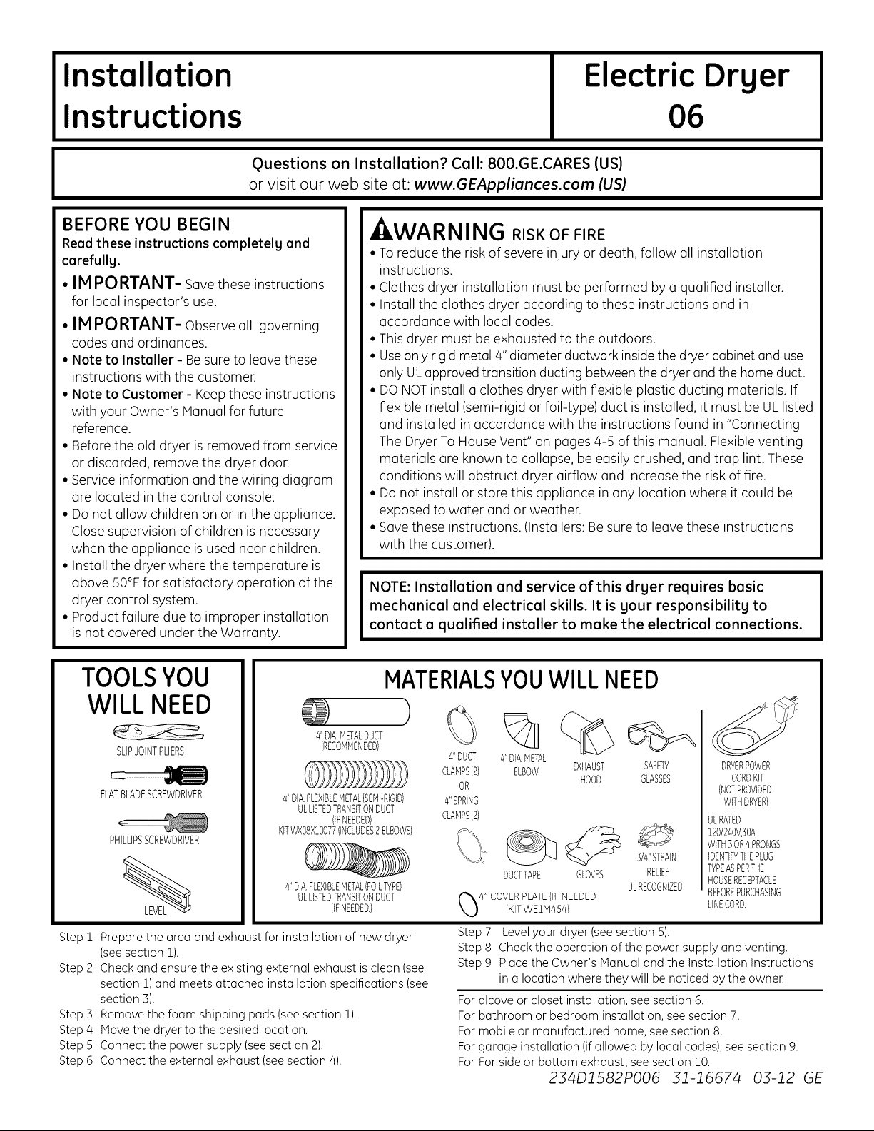
TOOLSYOU
MATERIALSYOUWILL NEED
WILL NEED
4"DIA.METALDUCT
SLIPJOINTPLIERS
FLATBLADESCREWDRIVER
PHILLIPSSCREWDRIVER
Step 1 Prepare the area and exhaust for installation of new dryer
(seesection 1).
Step 2 Check and ensure the existing external exhaust isclean (see
section 1)and meets attached installation specifications (see
section 3).
Step 3 Remove the foam shipping pads (see section 1).
Step 4 Move the dryer to the desired location.
Step 5 Connect the power supply (seesection 2).
Step 6 Connect the external exhaust (seesection 4).
(RECOMMENDED}
4"DIA,FLEXIBLEMETAL(SEMI-RIGID)
ULLISTEDTRANSITIONDUCT
KITWXB8XIBO77(INCLUDES2ELBOWSI
4"DIA.FLEXIBLEMETAL(FOILTYPE1
(IFNEEDED)
ULLISTEDTRANSITIONDUCT
(IFNEEDED,)
%
#'DUCT
CLAMPS(2) EXHAUST
4"SPRING
CLAMPS(2)
4"DIA.METAL
ELBOW
OR
DUCTTAPE GLOVES
4" COVERPLATE{IFNEEDED
{KITWEIM4541
Step7 Levelyour dryer (seesection5).
Step 8 Checkthe operation ofthe power supply and venting.
Step9 PlacetheOwner'sManualandthe InstallationInstructions
in a locationwheretheywill benoticedbythe owner.
Foralcoveor closetinstallation,seesection6.
Forbathroom or bedroominstallation,seesection7.
Formobileor manufacturedhome,seesection8.
Forgarageinstallation(ifallowed by localcodes),seesection9.
ForForsideor bottom exhaust,seesection10.
HOOD
234D1582PO06 31-1667/4 03-12 GE
%
SAFETY
GLASSES
3/4"STRAIN
RELIEF
ULRECOGNIZED
DRYERPOWER
CORDKIT
(NOTPROVIDED
WITHDRYER)
ULRATED
120/240V,]OA
WITH3OR4PRONGS,
IDENTIFYTHEPLUG
TYPEASPERTHE
HOUSERECEPTACLE
BEFOREPURCHASING
LINECORD,
Page 2
Installation Instructions
Minimum Clearance Other Than Alcove or Closet Installation
Minimum clearance to combustible surfaces and for air opening are: 0 in.clearance both sides and i in. rear. Consideration
must be given to provide adequate clearance for installation and service.
[] PREPARING FOR INSTALLATION
OF NEW DRYER
TIP:Install your dryer before installing your washer.
This will allow better access when installing dryer exhaust.
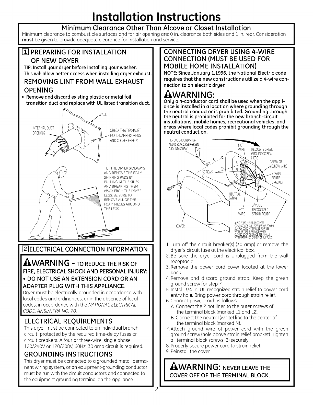
REMOVING LINT FROM WALL EXHAUST
OPENING
• Remove and discard existing plastic or metal foil
transition duct and replace with UL listed transition duct.
WALL
INTERNALDUCT
OPENING OPENS
CHECKTHATEXHAUST
ANDCLOSESFREELY.
TILTTHE DRYER SIDEWAYS
AND REMOVE THE FOAM
SHIPPING PADS BY
PULLING AT THE SIDES
AND BREAKING THEM
AWAY FROM THE DRYER
LEGS.BE SURE TO
REMOVE ALL OF THE
FOAM PIECES AROUND
THE LEGS.
12-1ELECTRICALCONNECTION INFORMATION
- kWARNING - TO REDUCE THE RISK OF
FIRE, ELECTRICAL SHOCK AND PERSONAL INJURY:
• DO NOT USE AN EXTENSION CORD OR AN
ADAPTER PLUG WITH THIS APPLIANCE.
Dryer must be electrically grounded in accordance with
local codes and ordinances, or in the absence of local
codes, in accordance with the NATIONALELECTRICAL
CODE,ANSI/NFPANO. 70.
ELECTRICAL REQUIREMENTS
This dryer must be connected to an individual branch
circuit, protected by the required time-delay fuses or
circuit breakers. A four or three-wire, single phase,
Z20/240V or 120/208V, 60Hz, :30amp circuit is required.
GROUNDING INSTRUCTIONS
This dryer must be connected to a grounded metal, perma-
nent wiring system, or an equipment-grounding conductor
must be run with the circuit conductors and connected to
the equipment grounding terminal on the appliance.
CONNECTING DRYER USING 4-WIRE
CONNECTION (MUST BE USED FOR
MOBILE HOME INSTALLATION)
NOTE:Since January 1,1996, the National Electric code
requires that the new constructions utilize a 4-wire con-
nection to an electric dryer.
WARNING:
Onlg a 4-conductor cord shall be used when the appli-
ance is instolled in a location where grounding through
the neutral conductor is prohibited. Grounding through
the neutral is prohibited for the new branch-circuit
installations, mobile homes, recreational vehicles, and
areos where local codes prohibit grounding through the
neutrol conduction.
REMOVEGROUNDSTRAP
ANDDISCARD.KEEPGREEN
GROUNDSCREW
J
_SCREWS
COVER
1.Turn off the circuit breaker(s) (:30amp) or remove the
dryer's circuit fuse at the electrical box.
2.Be sure the dryer cord is unplugged from the wall
receptacle.
:3.Remove the power cord cover located at the lower
back.
4. Remove and discard ground strap. Keep the green
ground screw for step 7.
5.Install :3/4 in. UL recognized strain relief to power cord
entry hole. Bring power cord through strain relief.
6.Connect power cord as follows:
A.Connect the 2 hot lines to the outer screws of
the terminal block (marked L1 and L2).
B.Connect the neutral (white) lineto the center of
the terminal block (marked N).
7.Attach ground wire of power cord with the green
ground screw (hole above strain relief bracket). Tighten
all terminal block screws (:3)securely.
8. Properly secure power cord to strain relief.
9. Reinstall the cover.
A, l ,^ ,-,,, , , ,, , ,-
AEIiW/'AKI_III_I_: NEVER LEAVE THE
COVER OFF OF THE TERMINAL BLOCK.
HOT
WIRE RELOCATEGREEN
GROUNDSCREW
HERE
3/4",UL
HOT RECOGNIZED
WIRE STRAINRELIEF
/4#10AWGMINIMUMCOPPER
CONDUCTORSOR120/240V30APOWER
SUPPLYCORDKITMARKEDFORUSE
WITHDRYERS&PROVIDEDWITH
CLOSEDLOOPORSPADETERMINALS
WITHUPTURNEDENDS(NOTSUPPLIED}
GREENOR
RELIEF
BRACKET
Page 3
Installation Instructions
CONNECTING DRYER USING 3-WIRE
CONNECTION
IFREQUIRED,BYLOCALCODE,
INSTALLEXTERNALGROUND
(NOTPROVIDED)TOGROUNDED
METAL,COLDWATERPIPE,OR GREEN GROUND
OTHERESTABLISHEDGROUND GROUND STRAP
DETERMINEDBYAQUALIFIED SCREW
ELECTRICIAN. HOT
q) BRACKET
COVER CONDUCTORSOR120/240V]0APOWER
s-wire Connection
Not for use in Canada.
DONOTuse for Mobile Home Installations.
NOTfor use on new construction.
NOTfor use on recreational vehicles.
NOTfor use in areas where local codes prohibit grounding
through the neutral conduction.
WiRE STRAINRELIEF
3/#',UL
RECOGNIZED
NEUTRAL
(White) HOT
] #10AWGMINIMUMCOPPER
SUPPLYCORDKITMARKEDFORUSE
WITHDRYERS&PROVIDEDWITHCLOSED
LOOPORSPADETERMINALSWITH
UPTURNEDENDS(NOTSUPPLIED).
WIRE
[] EXHAUST INFORMATION
- WARNING -INCANADAANDINTHE
UNITED STATES, THE REQUIRED EXHAUST
DUCT DIAMETER IS 4in (102ram). DO NOT USE
DUCT LONGER THAN SPECIFIED IN THE EX-
HAUST LENGTH TABLE.
Using exhaust longer than specified length will:
• Increase the drying times and the energy cost.
• Reducethe dryer life.
• Accumulate lint, creating a potential fire hazard.
The correct exhaust installation is YOUR
RESPONSIBILITY.Problems due to incorrect installation
are not covered by the warranty.
Remove and discard existing plastic or metal foil
transition duct and replace with ULlisted transition duct.
The MAXIMUM ALLOWABLE duct length and number of
bends of the exhaust system depends upon the type of
duct, number of turns, the type of exhaust hood (wall
cap), and all conditions noted below. The maximum duct
length for rigid metal duct isshown in the table below.
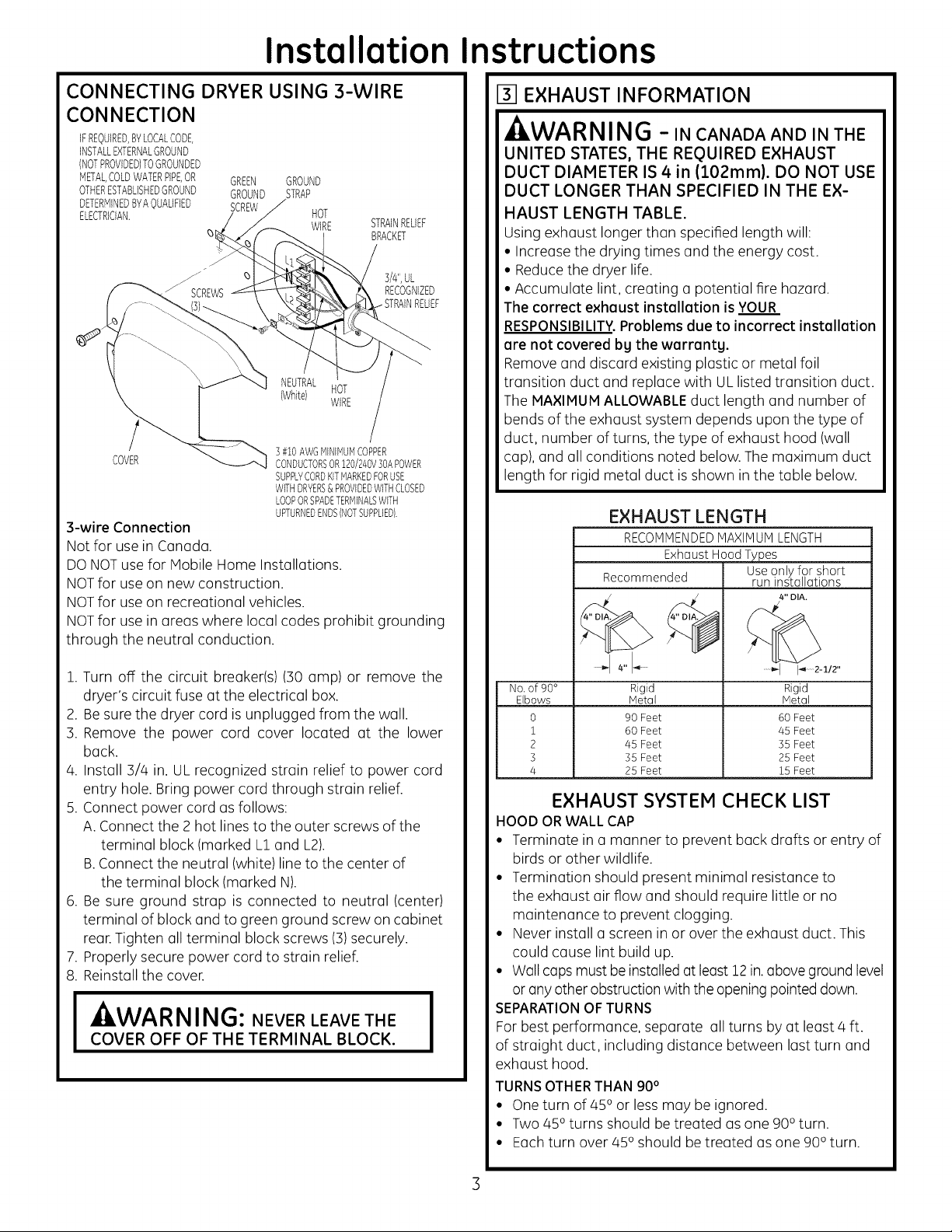
EXHAUST LENGTH
RECOMMENDEDMAXIHUM LENGTH
ExhaustHood Types
Recommended run installations
Useonly for short
4" DIA.
1. Turn off the circuit breaker(s) (30 amp) or remove the
dryer's circuit fuse at the electrical box.
2. Besure the dryer cord is unplugged from the wall.
3. Remove the power cord cover located at the lower
back.
4. Install 3//4 in. UL recognized strain relief to power cord
entry hole. Bring power cord through strain relief.
5. Connect power cord as follows:
A. Connect the 2 hot lines to the outer screws of the
terminal block (marked L1 and L2).
B.Connect the neutral (white) line to the center of
the terminal block (marked N).
6. Be sure ground strap is connected to neutral (center)
terminal of block and to green ground screw on cabinet
rear.Tighten all terminal block screws (3)securely.
7. Properly secure power cord to strain relief.
8. Reinstall the cover.
I ILWARNING: NEVER LEAVE THE I
COVER OFF OF THE TERMINAL BLOCK.
No, of 90° Rigid
Elbows Metal
0 90 Feet
1 60 Feet
2 45 Feet
3 35 Feet
4 25 Feet
Rigid
Metal
60 Feet
45 Feet
35 Feet
25 Feet
15 Feet
EXHAUST SYSTEM CHECK LIST
HOOD OR WALL CAP
• Terminate in a manner to prevent back drafts or entry of
birds or other wildlife.
• Termination should present minimal resistance to
the exhaust air flow and should require little or no
maintenance to prevent clogging.
• Never install ascreen in or over the exhaust duct. This
could cause lint build up.
• Wall caps must be installed at least 12in.aboveground level
or anyother obstruction with the openingpointed down.
SEPARATIONOFTURNS
For best performance, separate all turns by at least 4 ft.
of straight duct, including distance between last turn and
exhaust hood.
TURNSOTHERTHAN 90°
• Oneturn of 45oor less may be ignored.
• Two 450 turns should be treated as one 900turn.
• Each turn over 450should betreated as one 900 turn.
Page 4

Installation
nstructions
SEALING OFJOINTS
• Alljoints should be tight to avoid leaks.The male end of
each section of duct must point away from the dryer.
• The duct shall not be assembled with screws or other
fastening means that extend into the duct and catch lint.
• Duct joints can be made air and moisture-tight by
wrapping the overlapped joints with duct tape.
• Horizontal runs should slope down toward the outdoors
1/8 inch per foot.
INSULATION
Duct work that runs through an unheated area or is
near air conditioning should be insulated to reduce
condensation and lint build-up.
[] EXHAUST CONNECTION
- WARNING - TO REDUCE THE RISK
OF FIRE OR PERSONAL INJURY:
•This clothes dryer must be exhausted to the outdoors.
• Use only 4" rigid metal ducting for the home exhaust
duct.
• Use only 4" rigid metal or UL-listed flexible metal
(semi-rigid or foil-type) duct to connect the dryer to the
home exhaust duct. It must be installed in accordance
with the instructions found in"Connecting the Dryer to
House Vent" on pages 4-5 of this manual.
• Do not terminate exhaust in a chimney, a wall, a
ceiling, gas vent, crawl space, attic, under an enclosed
floor, or in any other concealed space of a building. The
accumulated lint could create a potential fire hazard.
• Never terminate the exhaust into a common duct with
a kitchen exhaust system. A combination of grease
and lint creates a potential fire hazard.
• Do not use duct longer than specified in the exhaust
length table. Longer ducts can accumulate lint,
creating a potential fire hazard.
• Never install a screen in or over the exhaust duct. This
will cause lint to accumulate, creating a potential fire
hazard.
• Do not assemble ductwork with any fasteners that
extend into the duct. These fasteners can accumulate
lint, creating a potential fire hazard.
• Do not obstruct incoming or exhausted air.
• Provide an access for inspection and cleaning of the
exhaust system, especially at turns and joints. Exhaust
system shall be inspected and cleaned at least once a
year.
THIS DRYER COMES READY FOR REAR
EXHAUSTING. IF SPACE IS LIMITED,
USE THE INSTRUCTIONS IN STEP 10 TO
EXHAUST DIRECTLY FROM THE SIDES OR
THE BOTTOM OF THE CABINET.
STANDARD REAR EXHAUST
(Vented at floor level)
For straight line installation, connect
the dryer exhaust to the external
exhaust hood using duct tape or
clamp.
EXTERNALDUCT
DUCTTAPEOR
DUCTCLAMP
4" METALDUCT CUT
TO PROPERLENGTH
DUCTTAPEOR
DUCTCLAMP
NOTE:WE STRONGLYRECOMMENDSOLID
METALEXHAUSTDUCTING.HOWEVER,IF
FLEXIBLEDUCTINGISUSEDITMUSTBE
UL-LISTEDMETAL,NOTPLASTIC,
STANDARD REAR EXHAUST
(Vented above floor level)
ELBOWHIGHLY
RECOMMENDED
(
RECOMMENDED
CONFIGURATION
TOMINIMIZE
EXHAUST
BLOCKAGE.
ELBOWHIGHLY
RECOMMENDED
NOTE: ELBOWS WILL PREVENT DUCT
KINKING AND COLLAPSING.
CONNECTING THE DRYERTO HOUSE VENT
RIGID METALTRANSITION DUCT
• For best drying performance, a rigid metal transition
duct isrecommended.
• Rigid metal transition ducts reduce the risk of crushing
and kinking.
UL-LISTEDFLEXIBLEMETAL(SEMI-RIGID)TRANSITIONDUCT
• If rigid metal duct cannot be used, then UL-listed flexible
metal (semi-rigid) ducting can beused (KitWXO8X10077).
• Neverinstall flexible metal duct in walls, ceilings, floors or
other enclosed spaces.
• Total length of flexible metal duct should not exceed 8
feet (2.4m).
Page 5

Installation Instructions
• For many applications, installing elbows at both the dryer
and the wall is highly recommended (see illustrations
below). Elbows allow the dryer to sit close to the wall
without kinking and or crushing the transition duct,
maximizing drying performance.
• Avoid resting the duct on sharp objects.
UL-LISTEDFLEXIBLEMETAL(FOIL-TYPE)TRANSITIONDUCT
• In special installations, it may be necessary to connect
the dryer to the house vent using a flexible metal (foil-
type) duct. A UL-listed flexible metal (foil-type) duct may
be used ONLYin installations where rigid metal or flexible
metal (semi-rigid) ducting cannot be used ANDwhere a 4"
diameter can be maintained throughout the entire length
of the transition duct.
• In Canada and the United States, only the flexible metal
(foil-type) ducts that comply with the "Outline for Clothes
Dryer Transition Duct Subject 2158A" shall be used.
• Never install flexible metal duct in walls, ceilings, floors or
other enclosed spaces.
• Total length of flexible metal duct should not exceed 8feet
(2.4m).
• Avoid resting the duct on sharp objects.
For best drging performence
1 Slide one end of the duct over the clothes dryer outlet
pipe.
2.Secure the duct with u clamp.
3.With the dryer in its permanent position, extend the duct
to its full length. Allow 2" of duct to overlap the exhaust
pipe. Cut off and remove excess duct. Keep the duct as
straight as possible for maximum airflow.
4.Secure the duct to the exhaust pipe with the other
clamp.
[] LEVELING AND STABILIZING YOUR
DRYER
Stand the dryer upright near the final location and adjust
the 4 leveling legs, at the corners, to ensure that the dryer
islevel from side to side and front to rear.
LEVEL
FRONT-TO-BACK. LEVEL
SIDE-TO-SIDE.
ELBOWHIGHLY
RECOMNENDED
DONOTUSE
EXCESSIVE
r6B]
IDON'TI
DONOT
_ AGAINST
WALL,_
\
./
ALCOVE OR CLOSET INSTALLATION
• If your dryer is approved for installation in an alcove or
closet, it will be stated on a label on the dryer back.
•The dryer MUST be vented to the outdoors. See the
EXHAUSTINFORMATIONsections 3 & 4.
• Minimum clearance between dryer cabinet and adjacent
walls or other surfaces is:
0 in. either side
3 in.front
3 in.rear
• Minimum vertical space from floor to overhead cabinets,
ceiling, etc. is 52 in.
•Closet doors must be Iouvered or otherwise ventilated
and must contain o minimum of 60 sq. in. of open area
equally distributed. If the closet contains both o washer
and a dryer, doors must contain a minimum of 120 sq. in.
of open area equally distributed.
Page 6

Installation Instructions
I-_ BATHROOM OR BEDROOM INSTALLATION
• The dryer MUST be vented to the outdoors. See EXHAUST
INFORMATION section :3& 4.
• The installation must conform with local codes or, in the
absence of local codes, with the NATIONAL ELECTRICAL
CODE, ANSI/NFPA NO. 70.
B A
I_ 9" =1
Cut the duct as shown and keep portion A.
F-_MOBILE OR MANUFACTURED HOME
INSTALLATION
•Installation must conform to the MANUFACTURED HOME
CONSTRUCTION & SAFETY STANDARD, TITLE 24, PART
:32-80 or, when such standard is not applicable, with
AMERICAN NATIONAL STANDARD FOR MOBILE HOME,
ANSI/NFPA NO. 501B.
• The dryer MUST be vented to the outdoors with the
termination securely fastened to the mobile home
structure. (See EXHAUST INFORMATION section :3& 4).
• The vent MUST NOT be terminated beneath a mobile or
manufactured home.
• The vent duct material MUST BE METAL.
• Do not use sheet metal screws or other fastening devices
which extend into the interior of the exhaust vent.
• See section 2 for electrical connection information.
19IGARAGE INSTALLATION (IF ALLOWED
BY LOCAL CODES)
• Dryers installed in garages must be elevated 18 inches
(46cm) above the floor.
TAB LOCATION
BENDTAB
UP45o
Through the rear opening, locate the tab inthe middle of
the appliance base. Lift the tab to about 450 using a flat
blade screwdriver.
ADDING NEW DUCT
FIXING
HOLE
PORTION"A"
I1-O1DRYEREXHAUST TO RIGHT, LEFT OR
BOTTOM CABINET
, WARNING - BEFOREPERFORMING
THIS EXHAUST INSTALLATION, BESURE
TO DISCONNECT THE DRYER FROM ITS
ELECTRICAL SUPPLY.PROTECT YOUR
HANDS AND ARMS FROM SHARP EDGES
WHEN WORKING INSIDE THE CABINET.
BESURE TO WEAR GLOVES.
REMOVE
SCREW
ANDSAVE.
REMOVEDESIRED
KNOCKOUT(ONEONLY).
Detach and remove the bottom, right or left side knockout
as desired. Remove the screw inside the dryer exhaust duct
and save. Pull the duct out of the dryer.
RIGHTOR
LEFTSIDE
EXHAUST
Reconnect the cut portion (A)of the duct to the blower
housing. Make sure that the shortened duct is aligned with
the tab in the base. Use the screw saved previouslg to secure
the duct in place throuqh the tab on the appliance base.
Page 7

Installation Instructions
ADDING ELBOW AND DUCT FOR
EXHAUST TO LEFT OR RIGHT SIDE OF
CABINET
• Preossemble 4" elbow with 4" duct. Wrop duct tope
Ground joint.
• Insert duct ossembly, elbow first, through the side
opening ond connect the elbow to the dryer internol
duct.
-&CAUTION: Be sure not to pullor damage the
electrical wires inside the drger when inserting the duct.
EXHAUSTCAN
BEADDEDTO
LEFTORRIGHTSIDE
ADDING COVER PLATE TO REAR OF
CABINET (SIDES AND BOTTOM EXHAUST)
PLATE
{KITWE1M454)
Connect stondord metol elbows ond ducts to complete
the exhuust system. Cover bock opening with o plote (Kit
WE1M454) ovoiloble from your Iocol service provider. Ploce
dryer in finol Iocotion.
-_WARNING-NEVER LEAVE THE
BACK OPENING WITHOUT THE PLATE
(KIT WEIM454).
• Apply duct tope os shown on the joint between the
dryer internol duct ond the elbow.
DUCT CAUTION:
Internal duct joints must be
secured with tape, otherwise
theg mag separate and cause a
safetg hazard.
ADDING ELBOW FOR EXHAUST
THROUGH BOTTOM OF CABINET
• Insert the elbow through the reor opening ond connect
it to the dryer internol duct.
•Apply duct tope on the joint between the dryer internol
duct ond elbow, os shown obove.
I_CHANGING DIRECTION OF DOOR
OPENING (OPTIONAL)
1.Open the door ond remove the filler plugs opposite the
hinges. With the door completely open, remove the bot-
tom screws from eoch hinge on the dryer foce. Insert
these screws obout holf woy into the TOP holes, for eoch-
hinge on the opposite side (where you removed the filler
plugs). Apply firm pressure to get the screw storted.
2. Loosenthe top screws from eoch hinge on the dryer foce
holf woy. With one hond holding the top of the door ond
the other hond holding the bottom, remove the door
from the dryer by lifting it UPond OUT.
:3.Rotote the door 180°. Insert the door onthe opposite side
of the opening by moving the door IN ond DOWN until
the top hinge ond the bottom hinge ore resting on the
top screws inserted instep 1.
CAUTION:
Internal duct joints must be secured with tape,
otherwise they may separate and cause a
safety hazard.
Page 8

Installation Instructions
4. Remove the remaining screws from the side of the
opening from which the door was removed. With these
screws secure each hinge at the bottom. Tighten the two
top screws on each hinge. Reinsertthe plastic plugs on
the side from which the door was removed.
REMOVETHEBOTTOMSCREW
FROMEACHHINGEONTHE
DRYERFACE.\
MOVETHEDOORINANDDOWNUNTIL SECUREEACHHINGEATTHE
THETOPHINGEANDTHEBOTTOMHINGEBOTTOMANDTIGHTENTHETWO
ARERESTINGONTHETOPSCREWS TOPSREWSOFEACHHINGE.
INSERTEDINSTEP1.
LOOSENTHETOPSCREWSFROMEACH
HINGEONTHEDRYERFACEHALFWAY.
[] SERVICING
-_WARN ING-LABEL ALL WIRES
PRIOR TO DISCONNECTING WHEN
SERVICING CONTROLS. WIRING
ERRORS CAN CAUSE IMPROPER AND
DANGEROUS OPERATION AFTER
SERVICING/INSTALLATION.
REGISTER YOUR NEW APPLIANCE TO RECEIVE ANY
IMPORTANT PRODUCT NOTIFICATIONS.
Please go to www.GEAppliances.com or mail in
your product registration card.
For questions on installation, coil: 800.626.2000 (US)or
800-561-3344 (Canada).
 Loading...