

GE DASH 3000 V5, DASH 4000 V5 Quick Reference Manual
BEDSIDE MONITORING
Dash 3000/4000 V5
TAB
TRIM
COVER &
NON-TAB
TRIM
Quick Reference Guide
© 2004 General Electric Company
PN: 0304-CS-QRGD Rev. A
2018408-010
COVER &
NON-TAB
TRIM
TAB
TRIM
BEDSIDE MONITORING
Dash 3000/4000 V5
TAB
TRIM
COVER &
NON-TAB
TRIM
Quick Reference Guide
COVER &
NON-TAB
TRIM
TAB
TRIM
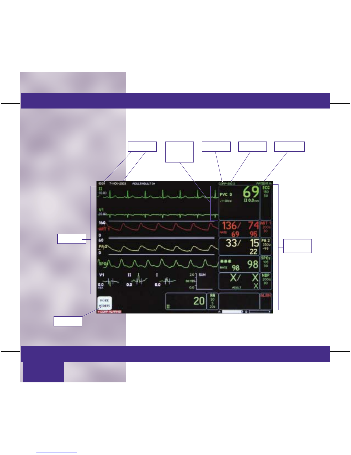
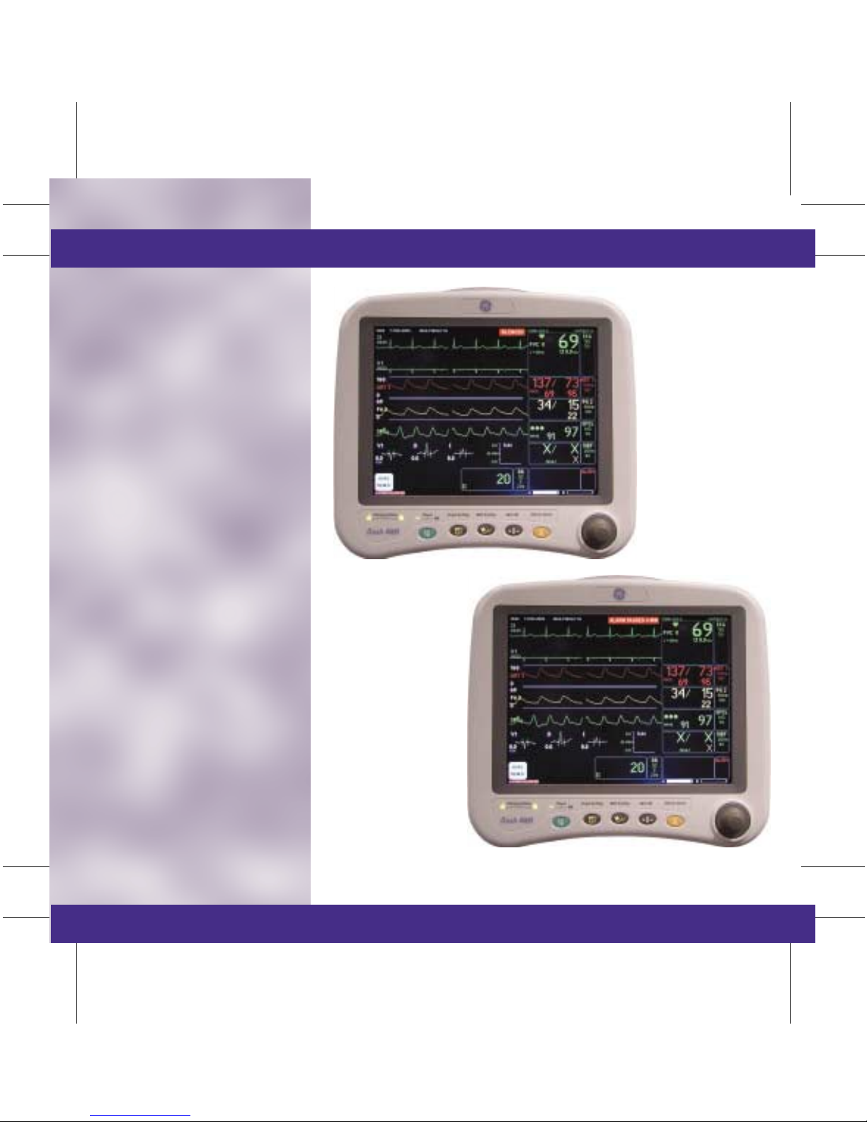
Components
■ Display
• Date
• Time
• Unit Name
• Bed Number
• Patient Name
• Parameter
Window
• More Menus
• Waveforms
Time / Date
ECG
Parameter
Window
Unit Name Bed Number
TAB
TRIM
COVER &
NON-TAB
TRIM
Patient Name
Waveforms
More Menus
Basic Use/
Admit/Discharge
Parameter
Windows
COVER &
NON-TAB
TRIM
TAB
TRIM
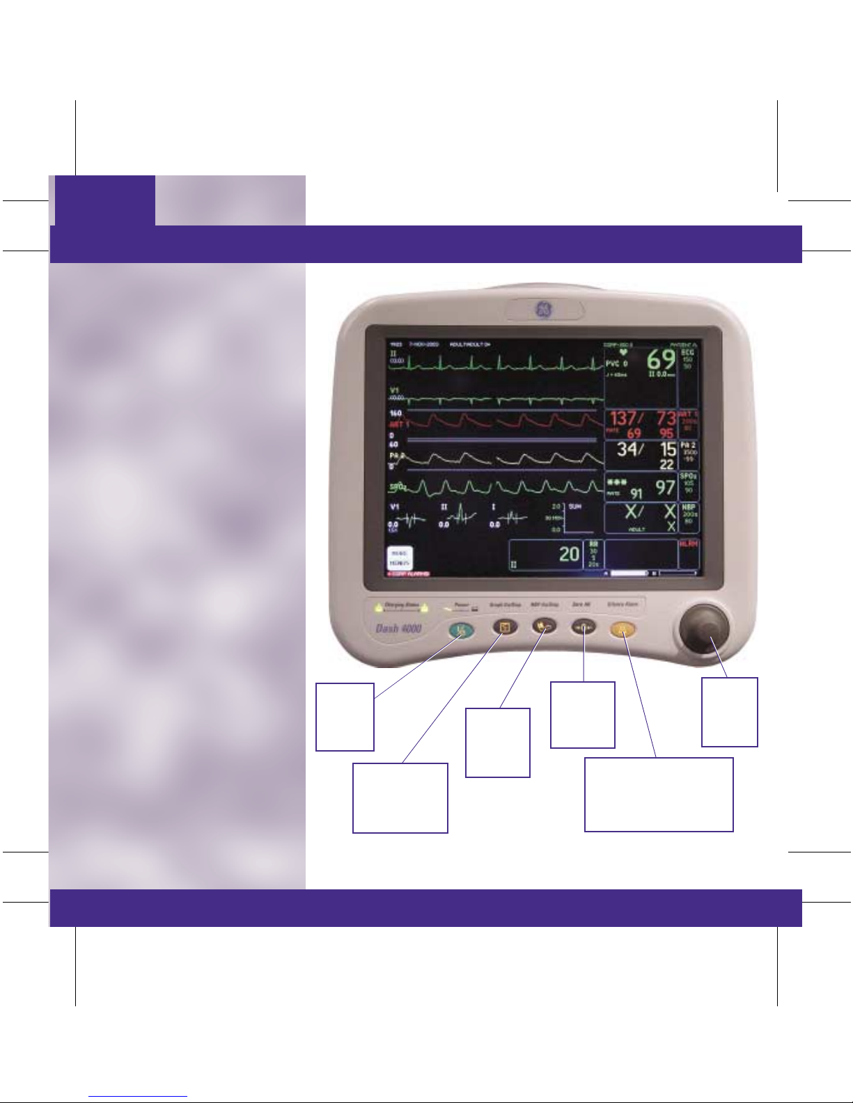
Basic Use/
Admit/Discharge
The Basics
■ Direct Action Keys
■ Operations
• Trim Knob: The Trim Knob
is found on the monitor or
remote control and is used for
highlighting and selecting
menu options.
– Turn the Trim Knob to
highlight desired menu
options.
– Once you have highlighted
the menu option, press to
select.
TAB
TRIM
COVER &
NON-TAB
TRIM
POWER:
Tur ns
Display
On or Off
GRAPH GO/STOP:
Starts and Stops
Manual Strips
and Print Window.
NBP
GO/STOP:
Starts and
Stops NBP.
ZERO ALL:
Zeros
Invasive
Pressures.
SILENCE ALARM:
Silences and Pauses Alarms.
Also Serves as a
Quick Admit Key
TRIM
KNOB:
Turn and
Push.
COVER &
NON-TAB
TRIM
TAB
TRIM
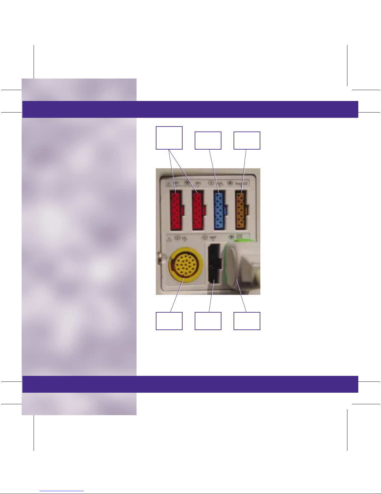
■ Patient Cable Connectors
• All patient cable connectors
are located on the side of the
monitor.
■ Definition of Terms
• Hardwire: This means that
the ECG signal is being
acquired from a cable
attached to the patient and
connected to a bedside
monitor.
• Telemetry: This means that
the ECG signal is being
acquired from a telemetry
transmitter/transceiver. This
patient is able to ambulate
without being limited by a
cable.
• TTX: Refers to a telemetry
transmitter/transceiver.
RED:
Invasive
Pressures
BLUE:
SPO
TAB
TRIM
COVER &
NON-TAB
TRIM
BROWN:
2
CO / Temp
YELLOW:
CO
2
BLACK:
NBP
GREEN:
ECG
COVER &
NON-TAB
TRIM
TAB
TRIM
■ Silence Alarm
• Pressing the Silence Alarm key
once will silence an active
alarm for one minute. The
message SILENCED will
appear on the display. Any
new alarm at an equal or
greater priority will sound.
NOTE: If Crisis Alarm Breakthrough is set in defaults, all crisis
alarms will break through Alarm Silence and Alarm Pause.
• Pressing the Silence Alarm key
twice if an alarm is sounding
will start an ALARM PAUSE.
The length of pause will vary
depending on the monitor’s
mode. The message ALARM
PAUSE will appear on the
display.
NOTE: Alarm Pause Lengths:
— Adult ICU Mode: 5 minutes.
— Neonatal ICU Mode: 3 minutes.
— Operating Room Mode: 5 minutes. 15 minutes,
Alarm Paused (permanent pause).
• Alarms will reactivate if the
Silence Alarm key is pressed
again.
• An Alarm Pause will
immediately be activated if
the Silence Alarm key is
pushed in the absence of an
alarm.
TAB
TRIM
COVER &
NON-TAB
TRIM
COVER &
NON-TAB
TRIM
TAB
TRIM
Monitor Applications
The bedside monitor can be used in
four different ways depending on
hospital need. Differences between
each application will be apparent in
the monitor’s admit menu.
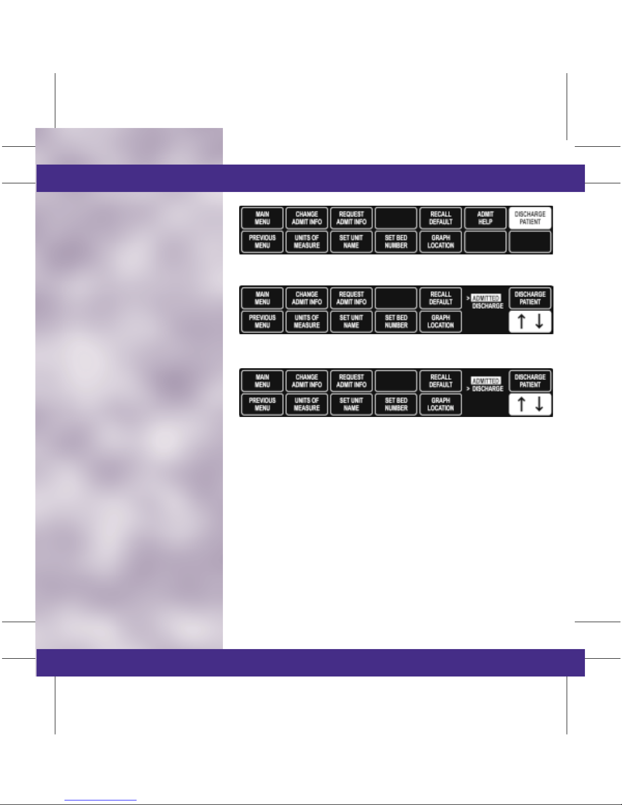
Standard
This application uses a monitor
mounted in a room. It has only
hardwire capability and does not
accommodate telemetry.
■ To Admit a Patient
• Select MORE MENUS.
• Select ADMIT MENU.
• Select ADMIT PATIENT.
NOTE: The Admit key, on the front of the monitor, can also be
used to admit the monitor.
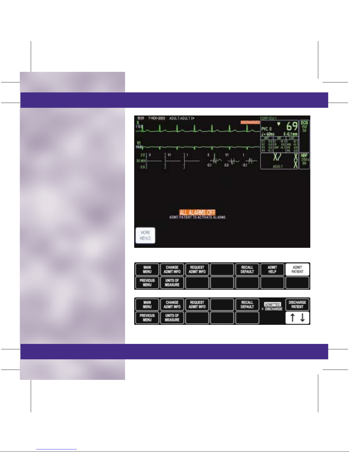
■ To Discharge a Patient
• Remove all ECG leads from
the patient.
• Select MORE MENUS.
• Select ADMIT MENU.
• Select DISCHARGE
PATIENT.
• Turn the Trim Knob to move
the cursor in front of
Discharge and press to select.
• A message DISCHARGED
and ALL ALARMS OFF will
appear on the display when
the monitor is in a discharged
mode.
TAB
TRIM
COVER &
NON-TAB
TRIM
COVER &
NON-TAB
TRIM
TAB
TRIM

■ How to Enter Demographic
Information:
• Select MORE MENUS.
• Select ADMIT MENU.
• Select CHANGE ADMIT
INFO. An information
window with menu options
is displayed.
• Rotate the Trim Knob
control to move the pointer
(>); repeat the press, turn,
press process to enter
characters or make
selections.
• Select RETURN after all
information is entered.
• Select desired option:
SAVE CHANGES or DO
NOT SAVE CHANGES.
TAB
TRIM
COVER &
NON-TAB
TRIM
■ Recall Defaults:
• This menu allows the
clinician to recall previously
named monitor defaults
while monitoring an
admitted patient.
• Up to five sets of defaults
can be programmed.
COVER &
NON-TAB
TRIM
TAB
TRIM
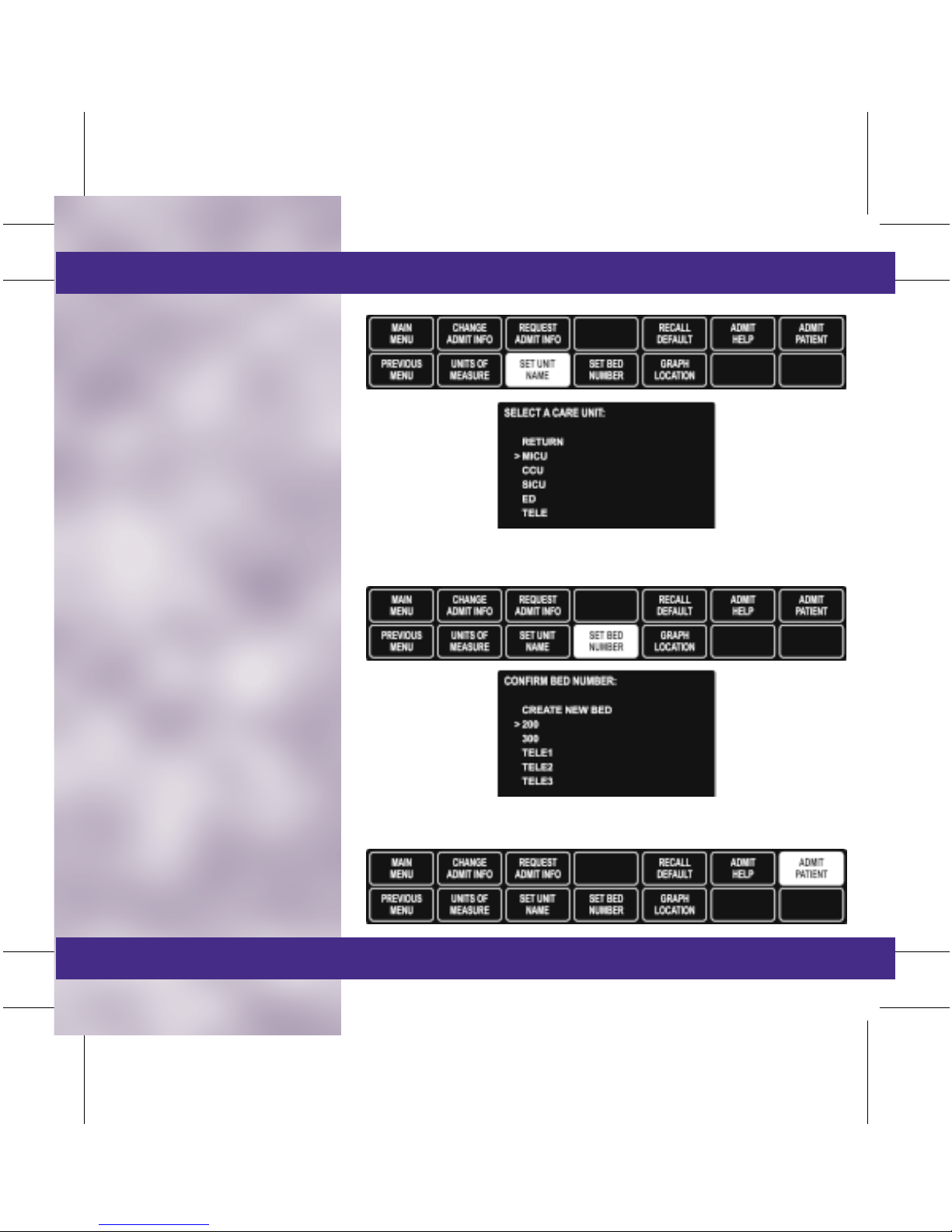
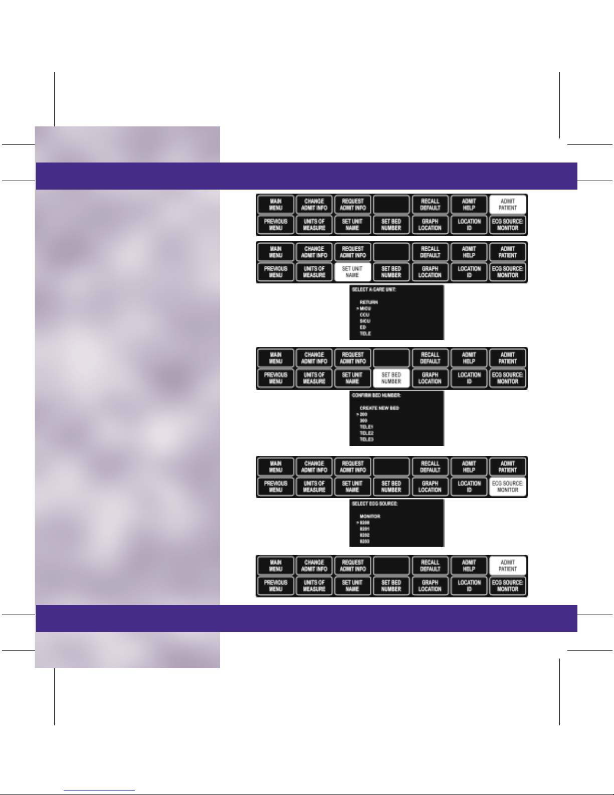
Rover
This application allows the monitor
to be moved or “roved” to the
patient’s bedside. It has only
hardwire capability and does not
accommodate telemetry.
■ To Admit a Patient
• Connect the AC Power source.
• Connect the Network cable.
NOTE: This step is not required when using wireless
Dash monitors. It is required for all other Dash
monitors.
• Push the Power button to
activate the display.
• Select MORE MENUS.
• Select ADMIT MENU.
• Select SET UNIT NAME.
• From the information window,
move cursor in front of the
desired unit.
• Select BED SET NUMBER.
• From the information window,
move cursor in front of the
desired bed number.
• Select ADMIT PATIENT.
NOTE: If the Unit Name or Bed Number windows do not
appear, check that the network cable is connected.
TAB
TRIM
COVER &
NON-TAB
TRIM
COVER &
NON-TAB
TRIM
TAB
TRIM
Rover
■ To Discharge a Patient
• Remove all ECG leads from
the patient.
• Select MORE MENUS.
• Select ADMIT MENU.
• Select DISCHARGE
PATIENT.
• Turn the Trim Knob to move
the cursor in front of
Discharge and press to select.
• A message DISCHARGED
and ALL ALARMS OFF will
appear on the display when
the monitor is in a discharged
mode.
NOTE: It is recommended to leave the network cable plugged
in and the Dash display on for two minutes following
discharge (if applicable).
• Push the Power button to turn
the display off.
• Store the monitor with AC
power cord plugged in and
display off.
TAB
TRIM
COVER &
NON-TAB
TRIM
COVER &
NON-TAB
TRIM
TAB
TRIM

Combo
This application uses a monitor
mounted in a room, but the ECG
data can be acquired from either a
hardwire cable from the monitor or
a telemetry transmitter/transceiver.
■ To Admit a Patient to
Hardwire
• Select MORE MENUS.
• Select ADMIT MENU.
• Select ADMIT PATIENT.
■ To Change the ECG
Source from Hardwire to
Telemetry
• Select MORE MENUS.
• Select ADMIT MENU.
• Select ECG SOURCE.
• Turn the Trim Knob to move
the cursor in front of the
desired telemetry transmitter/
transceiver number or
Monitor (Discharge Telem)
for hardwire capability from
the information window and
press to select.
TAB
TRIM
COVER &
NON-TAB
TRIM
NOTE: If the Telemetry transmitter/transceiver is being used
for the ECG signal, the TTX number will appear in the ECG
parameter box.
COVER &
NON-TAB
TRIM
TAB
TRIM

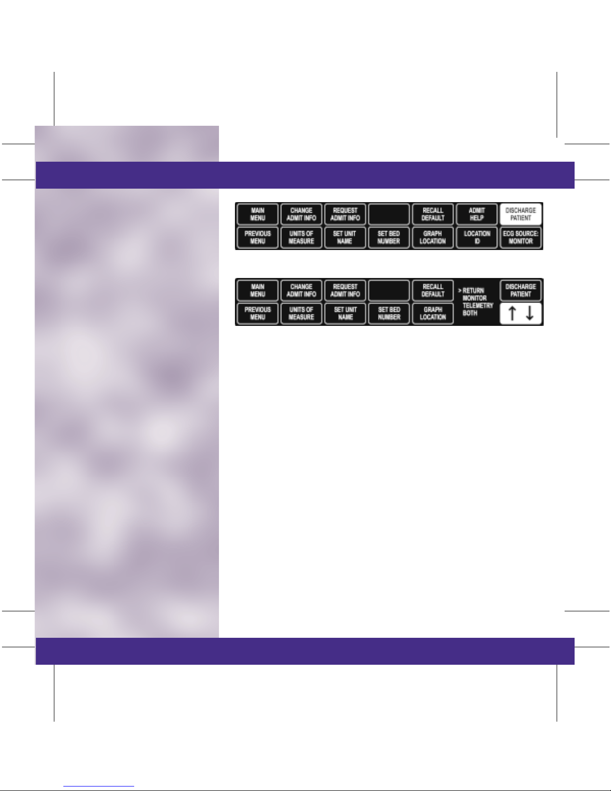
Combo
■ To Discharge a Patient:
• Remove all ECG leads from
the patient.
• Select MORE MENUS.
• Select ADMIT MENU.
• Select DISCHARGE
PATIENT.
• Turn the Trim Knob to move
the cursor in front of the
desired discharge option and
press to select.
– Return: Exit to Main Menu.
– Monitor: Discharges only
the bedside monitor.
– Telemetry: Discharges
patient from telemetry.
– Both: Discharges both the
monitor and telemetry.
• A message DISCHARGED
and ALL ALARMS OFF will
appear on the display when
the monitor is in a discharged
mode.
NOTE: When discharging ONLY the bedside monitor, all stored
vital sign data will be deleted. The only data which remain
available will be: HR, ST, PVC, and Alarm Histories.
TAB
TRIM
COVER &
NON-TAB
TRIM
COVER &
NON-TAB
TRIM
TAB
TRIM
Rover-Combo
This application combines the
mobility feature of Rover
monitoring with the telemetry
capabilities of Combo monitoring.
■ To Admit a Patient
• Connect the AC Power source.
• Connect the Network cable.
NOTE: This step is not required when using wireless
Dash monitors. It is required for all other Dash
monitors.
• Push the Power button to
activate the display.
• Select MORE MENUS.
• Select ADMIT MENU.
• Select SET UNIT NAME.
• From the information window,
move cursor in front of the
desired unit.
• Select SET BED NUMBER.
• From the information window,
move cursor in front of the
desired bed number.
• Select ECG SOURCE.
• From the information window,
move cursor in front of the
desired transmitter/
transceiver or monitor
(hardwire) and press to select.
NOTE: If the Unit Name, Bed Number or ECG Source windows
do not appear, check that the network cable is connected.
• Select ADMIT PATIENT.
TAB
TRIM
COVER &
NON-TAB
TRIM
COVER &
NON-TAB
TRIM
TAB
TRIM
Rover-Combo
■ To Discharge a Patient:
• Remove all ECG leads
from the patient.
• Select MORE MENUS.
• Select ADMIT MENU.
• Select DISCHARGE
PATIENT.
• Turn the Trim Knob to move
the cursor in front of the
desired discharge option and
press to select:
– Return: Exit to Main
Menu.
– Monitor: Discharges only
the bedside monitor.
– Telemetry: Discharges
patient from telemetry.
– Both: Discharges both the
monitor and telemetry.
NOTE: When discharging ONLY the bedside monitor, all stored
vital sign data will be deleted. The only data which remain
available will be: HR, ST, PVC, and Alarm Histories.
• A message DISCHARGED
and ALL ALARMS OFF will
appear on the display when
the monitor is in a discharged
mode.
• Push the Display On/Off
button to turn the display off.
NOTE: It is recommended to leave the network cable plugged
in and the Dash display on for two minutes following
discharge.
• Store the monitor with the AC
power cord plugged in and
the display off.
TAB
TRIM
COVER &
NON-TAB
TRIM
COVER &
NON-TAB
TRIM
TAB
TRIM
ECG
■ Skin Preparation and Lead
Placement:
The quality of the signal
received from the electrodes is a
direct result of skin prep and
lead placement.
• Clip or shave hair from
application sites.
• Gently rub the area with a
gauze pad to remove dead
skin cells.
• Cleanse site with alcohol or
mild soap and water.
• Dry skin completely.
• Apply electrodes according
to manufacturers
recommendations.
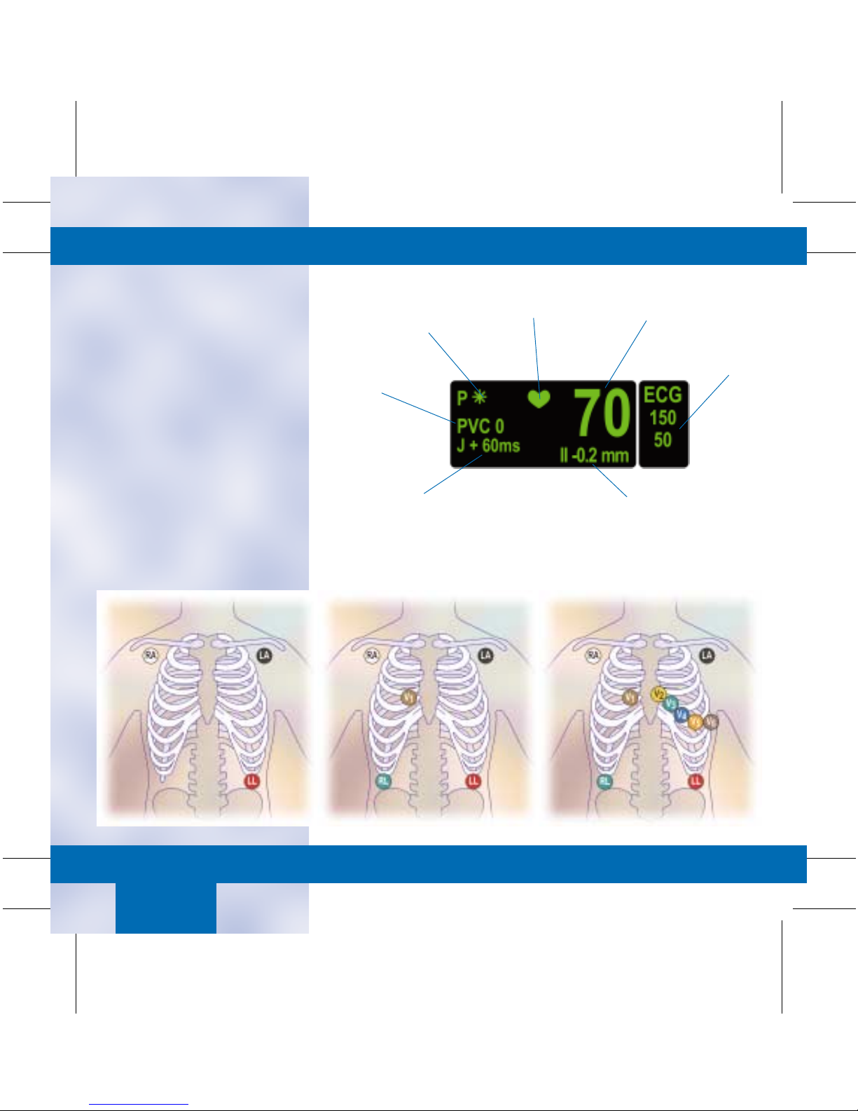
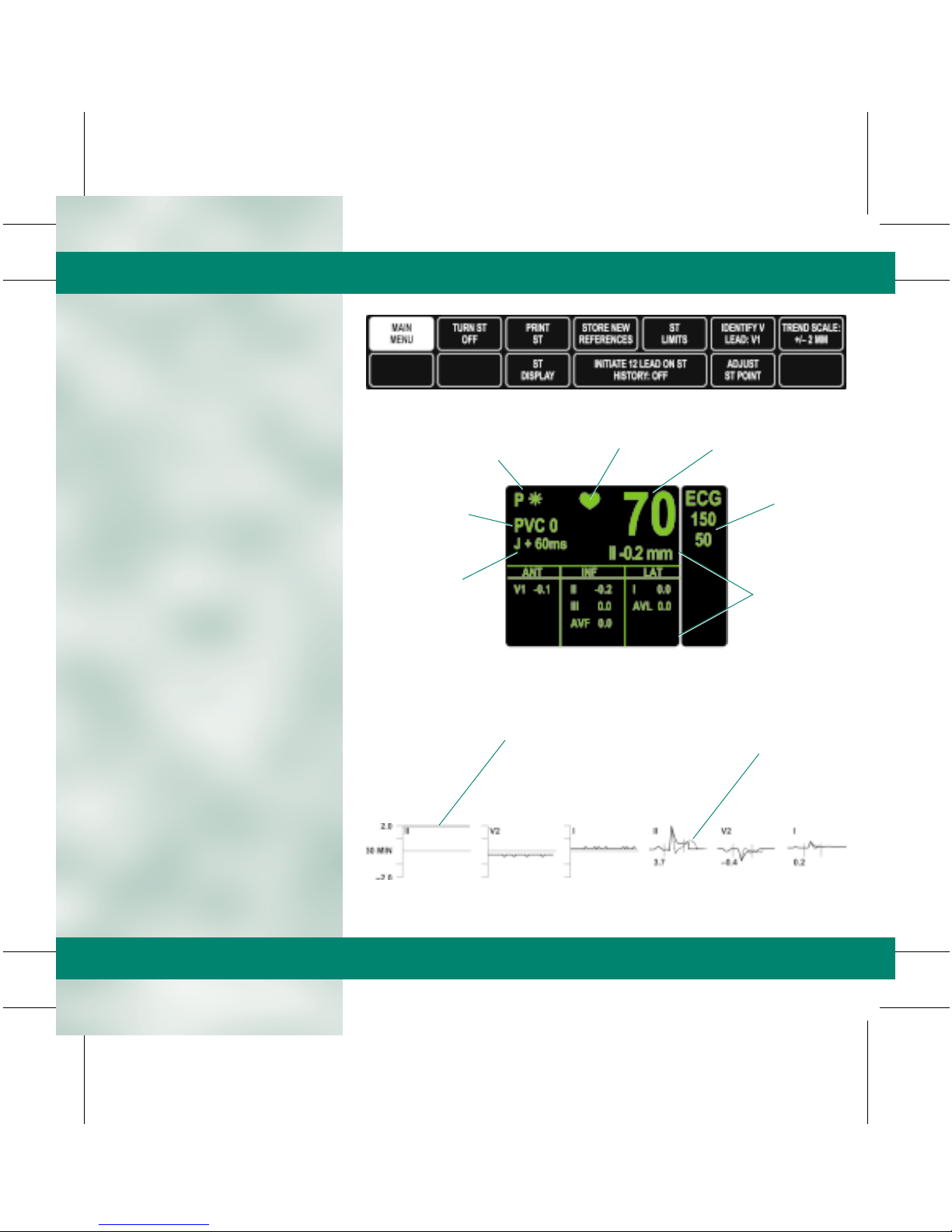
Pace Detection
Indicators
PVC Count
(Full Arrhythmia Only)
ST Measurement
Point
QRS
Indicator
TAB
TRIM
COVER &
NON-TAB
TRIM
Heart Rate
Heart Rate
Alarm Limits
ST Analysis Data
ECG/
Pace
COVER &
NON-TAB
TRIM
TAB
TRIM
ECG/
Pace
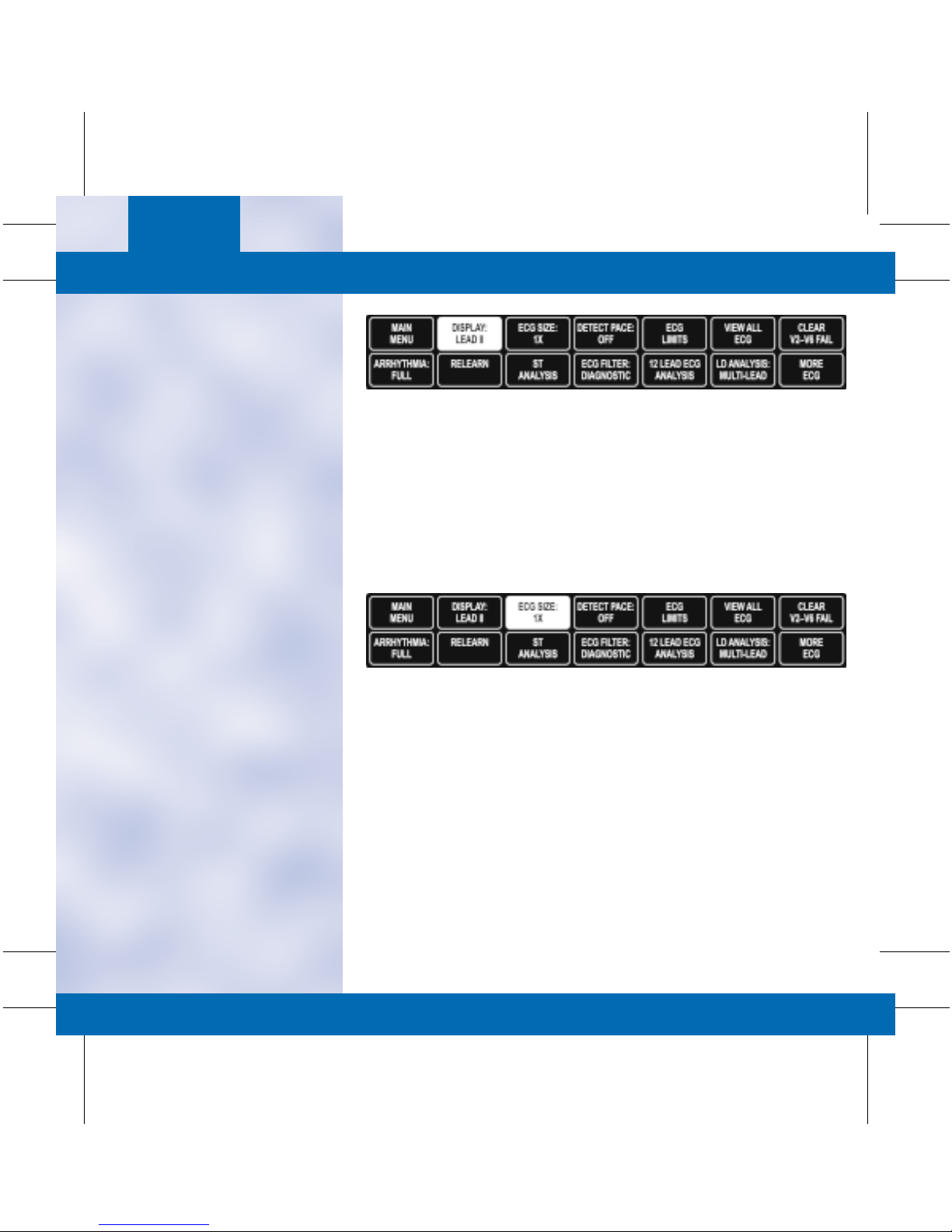
■ Display Lead: Top or first lead
displayed on the bedside and
graphed with alarms and
manual prints.
• To Change the Display Lead:
– Select ECG.
– Select DISPLAY LEAD II.
– A popup menu opens.
– Move the cursor in front of
the desired display lead and
press to select.
– Select MAIN MENU to
exit.
■ Size: Changes the size of all
ECG waveforms displayed and
graphed. 1X is the standard
size.
NOTE: At least a 0.5 millivolt QRS complex at standard size is
needed for beat detection.
• To Adjust ECG Size:
– Select ECG.
– Select ECG SIZE.
– Turn the Trim Knob to
highlight desired selection
and press to select.
– Select MAIN MENU to
exit.
TAB
TRIM
COVER &
NON-TAB
TRIM
COVER &
NON-TAB
TRIM
TAB
TRIM
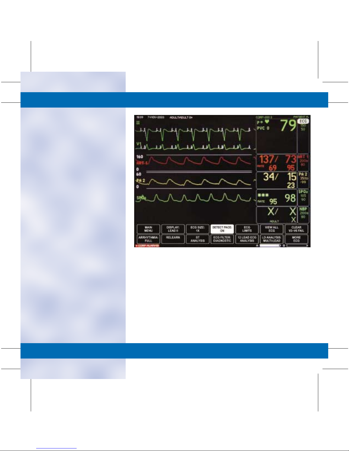
■ Detect Pace: Turns pacemaker
detection On/Off.
• Two different options of
pacemaker modes are
available. The clinician must
judge which mode is best for
each patient. Pace 2 is the
recommended pacemaker
detection mode. Pace 1
should be used if Pace 2 does
not adequately detect
pacemaker spikes.
• To Activate or Deactivate the
Pacemaker Mode:
– Select ECG.
– Select DETECT PACE.
– Turn the Trim Knob in
front of the desired
pacemaker mode and press
to select.
– Select MAIN MENU to
exit.
NOTE: A “P” appears in the ECG parameter window when pace
detection is enabled. An “*” will appear if a paced beat is
detected.
■ Pace 2 Mode: Analyzes
waveforms with the added
capability of minimizing the
chance of counting severe
residual pacemaker energy as a
QRS complex. Pace 2 may not
adequately detect all QRS
morphologies. Arrhythmia calls
such as Asystole or Pause may
be made with heart rate
identified as less than actual.
NOTE: Pacemaker patients should be kept under close
observation.
TAB
TRIM
COVER &
NON-TAB
TRIM
■ Pace 1 Mode: Analyzes the
presence of pacer spikes,
assesses the waveform for
residual pacemaker energy and
determines the presence of an
R-wave following the pacemaker
spike. If an event occurs during
the first few milliseconds
following the spike, it will be
counted as a paced spike.
COVER &
NON-TAB
TRIM
TAB
TRIM
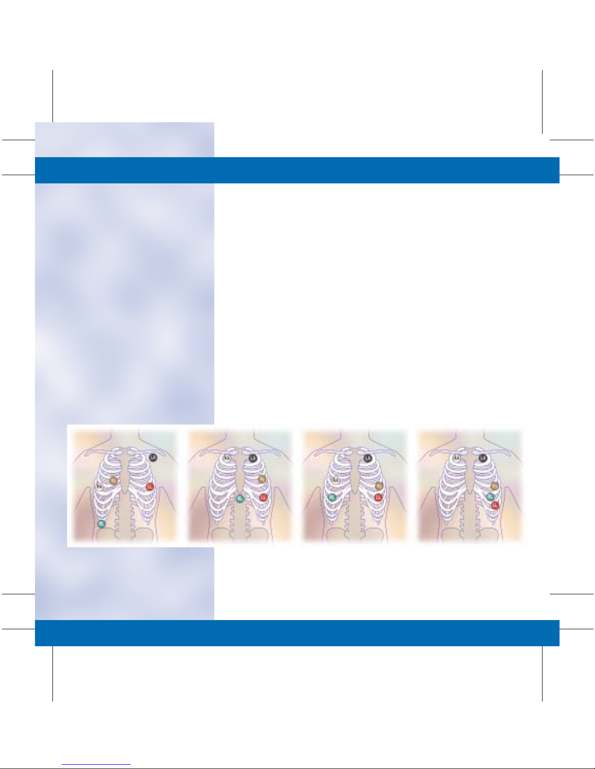
■ Guidelines for Successful
Pacemaker Monitoring:
• Multi-vector pace detection is
determined by simultaneous
analysis of the displayed ECG
Lead and the Vector Lead.
• Adequate pacemaker
detection is directly
dependant on the quality of
the ECG waveform. Proper
skin preparation and
electrode placement are
essential.
• Ensure that the pace detection
mode is activated.
• All detected pacemaker spikes
will appear upright, uniform
and white on the display
screen.
• If the monitor is not
adequately detecting
pacemaker spikes —
as evidenced by heart rate
double counting, pacemaker
spikes not detected, alarms for
low heart rate or asystole —
it is recommended that you
change the electrode
placement to a recommended
configuration.
• After changing electrode
placement, always RELEARN
the ECG waveform.
If adjusting the electrode
placement does not resolve
the detection issue, change
the pace detection mode to
Pace 1 and RELEARN.
TAB
TRIM
COVER &
NON-TAB
TRIM
Recommended Alternative Lead Placements
COVER &
NON-TAB
TRIM
TAB
TRIM
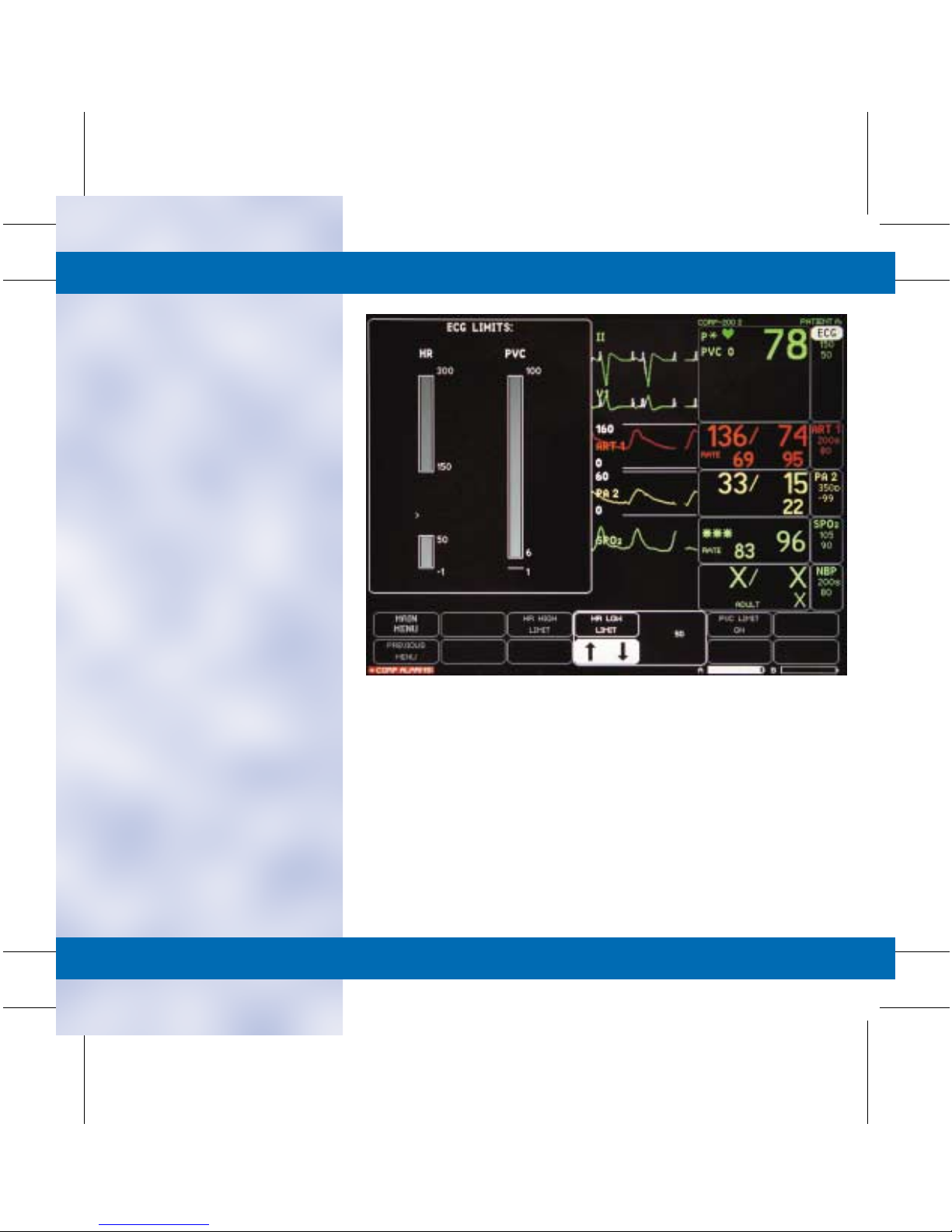
■ Limits:
• To Change the ECG Alarm
Limit:
– Select ECG.
– Select ECG LIMITS.
– Select desired alarm limit.
– Turn the Trim Knob to the
desired alarm limit and
press to select.
– Select MAIN MENU to
exit.
TAB
TRIM
COVER &
NON-TAB
TRIM
COVER &
NON-TAB
TRIM
TAB
TRIM
■ View All ECG: Allows six leads
of ECG to be viewed on the
display.
• To View All ECG:
– Select ECG.
– Select VIEW ALL ECG.
– Six waveforms will be
displayed.
– Press GRAPH GO/STOP to
print displayed leads.
– Press the Trim Knob to
remove displayed leads.
– Select MAIN MENU to
exit.
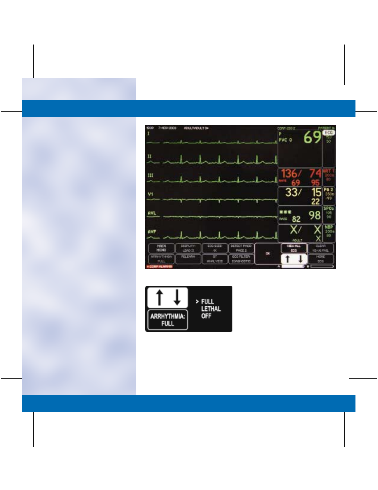
■ Arrhythmia: Arrhythmia
processing can be manually
changed to one of the following
conditions:
• Full: Expands detection to all
arrhythmia conditions
defined by the software level.
• Lethal: Arrhythmia
processing is limited to
Asystole, VFib/VTac and
VTach.
• Off: Disables all arrhythmia
alarms. Parameter alarms
remain active.
• To Change the Arrhythmia
Processing Mode:
– Select ECG.
– Select ARRHYTHMIA.
– Turn the Trim Knob to
move the cursor in front of
the desired arrhythmia
processing mode and press
to select.
– Select MAIN MENU to
exit.
TAB
TRIM
COVER &
NON-TAB
TRIM
COVER &
NON-TAB
TRIM
TAB
TRIM
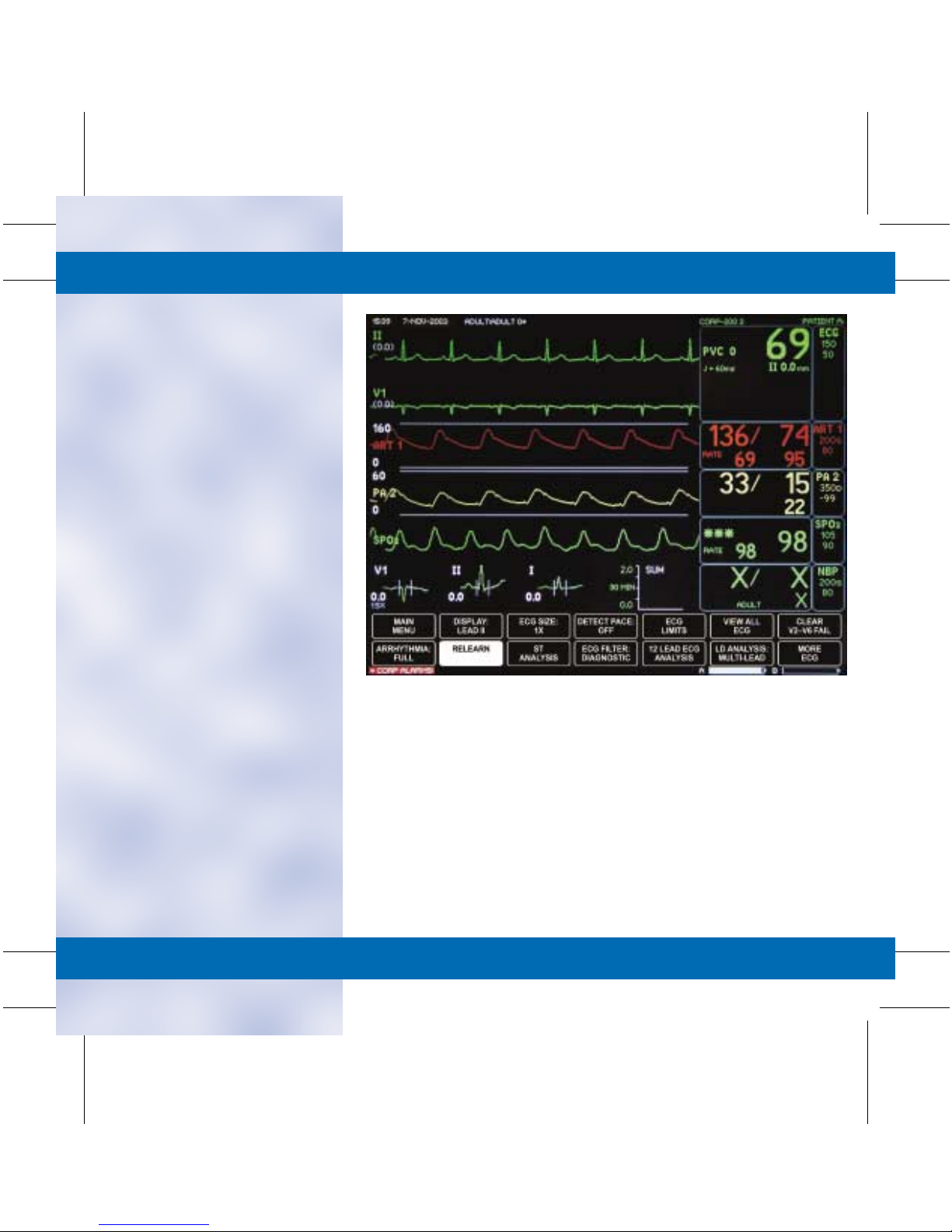
■ Relearn: During ECG
monitoring, it may be necessary
to relearn the ECG waveform if
a change in the patient’s normal
ECG pattern has occurred, or
the electrode placement has
changed.
• A change in the ECG pattern
could result in:
– Incorrect arrhythmia calls.
– Loss of ST measurement.
– Inaccurate heart rate
detection.
• To Relearn the ECG
Waveform:
– Select the ECG parameter
window.
– Select RELEARN.
– The ECG parameter
window will replace the HR
with an “X” and the
message “Learning” will
appear above the display
lead.
– Select MAIN MENU to
exit.
TAB
TRIM
COVER &
NON-TAB
TRIM
■ Turning the ECG Parameter
Off or On: See monitor setup
for details.
COVER &
NON-TAB
TRIM
TAB
TRIM
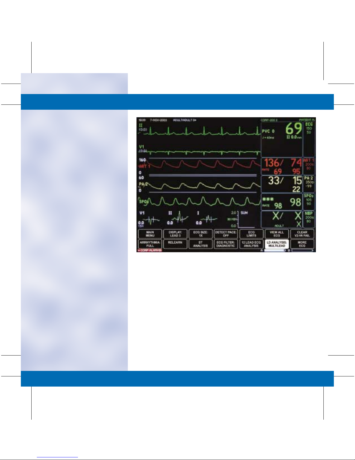
■ Single Lead vs. Multi-Lead:
This option examines ECG
leads utilized for arrhythmia
analysis.
• Multi-Lead Analysis examines
ECG leads I, II, III and V to
help eliminate false alarms
and improve the ability of the
system to:
– Detect beats that occur
isoelectric to a single chest
lead.
– Discriminate artifact that
appears in one lead
compared to other lead
vectors.
– Provides a “Smart Lead
Fail” feature where the
failed lead is identified and,
if available, another lead is
provided for display.
– Continue arrhythmia
processing after a lead
change.
• Single Lead Analysis uses
only the top displayed lead
to process heart rate and
arrhythmia information.
• Single lead analysis can be
beneficial when
troubleshooting heart rate
and arrhythmia alarms.
• To Change to Single Lead
Analysis:
– Select the ECG Parameter
Window.
– Select LD ANALYSIS:
MULTI-LEAD.
– Move the cursor in front of
Single Lead and press to
select.
– Select MAIN MENU to
exit.
TAB
TRIM
COVER &
NON-TAB
TRIM
COVER &
NON-TAB
TRIM
TAB
TRIM
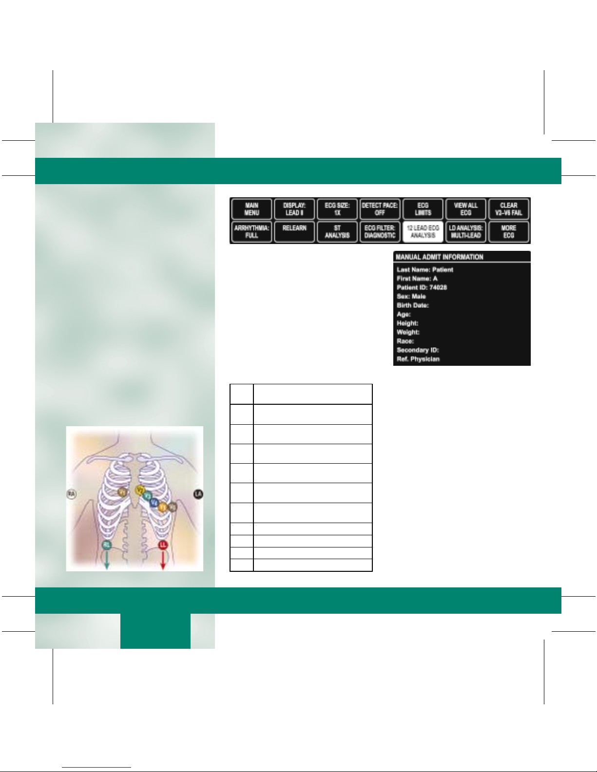
12 Lead ECG Analysis
NOTE: For the most accurate serial comparison, use the same
electrode configuration used on previous analysis.
■ To Obtain a 12-Lead on a
Patient:
• Place patient in a supine
position.
• Correctly identify and apply
all 10 electrodes.
• Select the ECG Parameter
Window.
• Select 12 LEAD ECG
ANALYSIS.
NOTE: Accurate demographics must be entered to ensure
proper analysis.
• Select ADMIT INFO
• Select CHANGE ADMIT
INFO.
Electrode Placement
• Enter Information:
– First Name: Completely
entered.
– Last Name: Completely
entered.
– Patient ID: Facility Specific,
(i.e., Medical Record
Number, Social Security
Number, etc.)
– Sex
Front
Leads
V1 Fourth intercostal space at the right
V2 Fourth intercostal space at the left
V3 Midway, between locations V2 and
V4 Mid-clavicular line in the fifth
V5 Anterior axillary line on the same
V6 Mid-axillary line on the same
LA Left deltoid or left wrist.
RA Right deltoid or right wrist.
LL Left thigh or left ankle.
LA Right thigh or right ankle
12 Lead Electrode Placement
sternal border; right chest.
sternal border; left chest.
V4; left chest.
intercostal space; left chest.
horizontal level as V4; left chest.
horizontal level as V4 & V5; left chest.
– Birth Date
– Age: Correct age impacts
the analysis.
– Height
– Weight
– Location ID: Identifies
origin of 12-lead to MUSE
for transmission.
(Set in defaults. For rover
modes, set in admit menu).
– Site Number: Identifies
hospital to MUSE for
transmission.
(Set in defaults).
NOTE: Depending on facility policy, other fields may be
required; i.e., Technician ID, Optional Field, Order Number.
(continued on next card)
TAB
TRIM
COVER &
NON-TAB
TRIM
COVER &
NON-TAB
TRIM
ST
12 Lead ECG
TAB
TRIM

ST
12 Lead ECG
(continued from previous card)
• Select 12 LEAD ECG NOW.
Message appears:
“PERFORMING ANALYSIS.
Please wait…” After 30
seconds, an unconfirmed
12-lead ECG Analysis window
will appear.
• Transmission and/or printing
options include the following:
– Transmit–Print: Send
12 lead for storage to
MUSE and print copy to
laser printer.
– Transmit: Send
12 lead for storage to
MUSE. No printed copy
on unit.
– Print: Print copy to laser
printer on unit. No 12 lead
stored at MUSE.
– Delete: Erase the analysis
without storing or printing.
– Return: Exit to 12-lead
menu.
TAB
TRIM
COVER &
NON-TAB
TRIM
12 Lead is completed. The last 12
lead analysis window is available for
review under REVIEW 12 LEAD
ECG TO TRANSMIT OR PRINT.
COVER &
NON-TAB
TRIM
TAB
TRIM
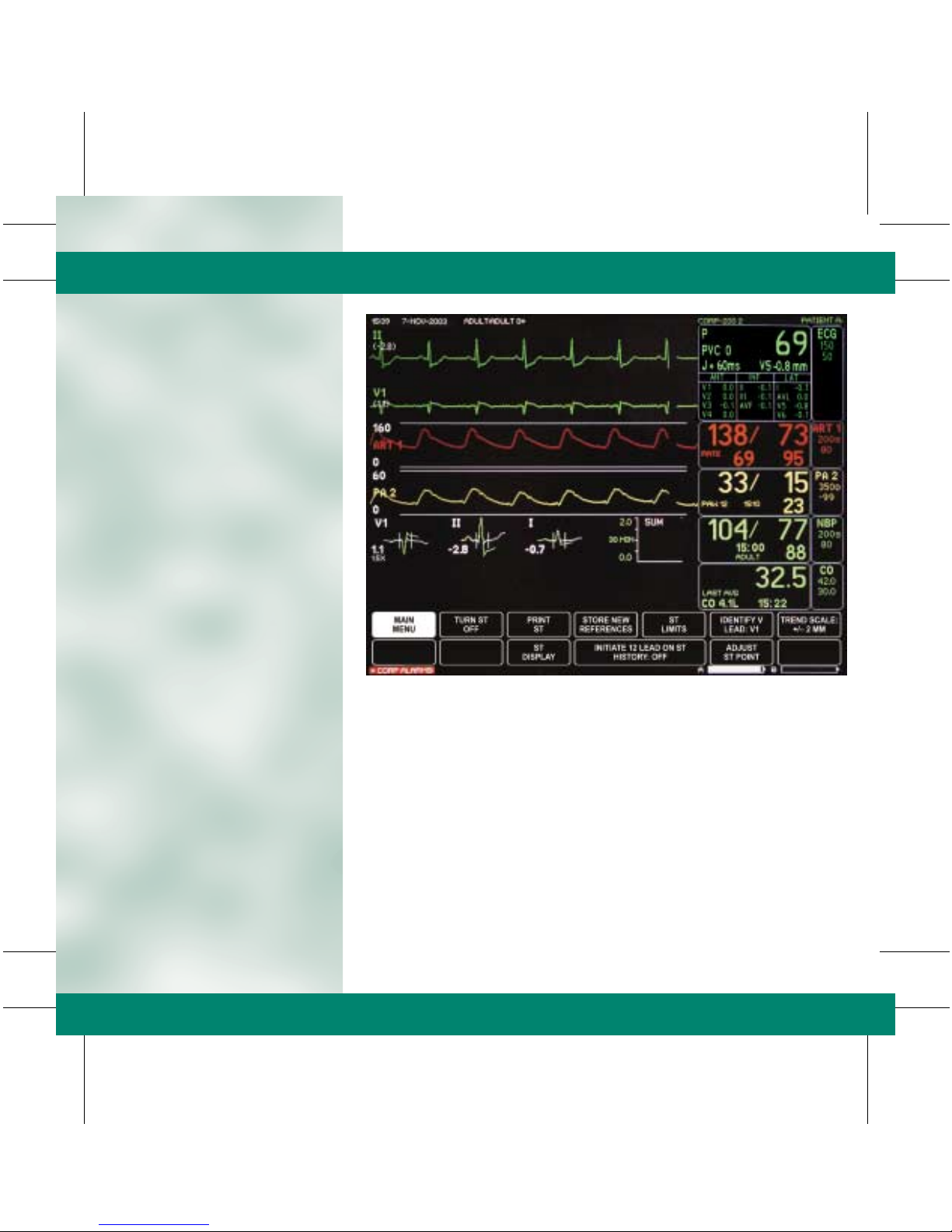
ST Analysis
■ ST Menu Options:
• ST information with trends
and complexes may appear in
a waveform position.
• ST by lead data may appear
in the ECG Parameter
Window.
• The lead with the most
deviation from the isoelectric
line appears in the ECG
window. The ST value is
updated regularly and
changes to the alarming lead
when limits are exceeded.
NOTE: ST options may vary depending on monitor default
configuration.
NOTE: The accuracy of the ST Analysis is dependent on the
placement of the electrodes.
Pace Detection
Indicators
PVC Count
(Full Arrhythmia Only)
ST Measurement
Point
QRS
Indicator
TAB
TRIM
COVER &
NON-TAB
TRIM
Heart Rate
Heart Rate
Alarm Limits
ST Analysis Data
■ ST Trends and Complexes
• The monitor has an ST
display which consists of
three 30-minute ST trends
OR three ECG complexes.
• A reference complex for each
of the selected leads is
displayed for visual reference
purposes when ST is on.
• The current complex is
superimposed (green) over
the reference complex (gray).
Data is outside of
the displayed
scale
The reference
complex is in back
of the current
complex
COVER &
NON-TAB
TRIM
TAB
TRIM
■ Turn ST ON/OFF: Turns ST
analysis off and returns to the
main menu.
• To Turn ST Analysis
Program Off:
– Select the ECG parameter
window.
– Select ST ANALYSIS.
– Select TURN ST OFF.
– Display automatically
returns to the Main Menu.
• To Turn ST Analysis
Program On:
– Select the ECG parameter
window.
– Select ST ANALYSIS.
– ST complexes and numerics
automatically appear on the
display.
– Select MAIN MENU to
exit.
■ Store New References:
Displays a new set of reference
complexes on the screen to use
as a visual reference.
• To store new references:
– Select the ECG parameter
window.
– Select ST ANALYSIS.
– Select STORE NEW
REFERENCES.
– Select YES from the popup
menu.
The reference complexes
shown on the display will
now reflect the current
complexes.
– Select MAIN MENU to
exit.
NOTE: Selecting STORE NEW REFERENCE does not affect
actual ST processing, it is for visual reference only.
TAB
TRIM
COVER &
NON-TAB
TRIM
COVER &
NON-TAB
TRIM
TAB
TRIM
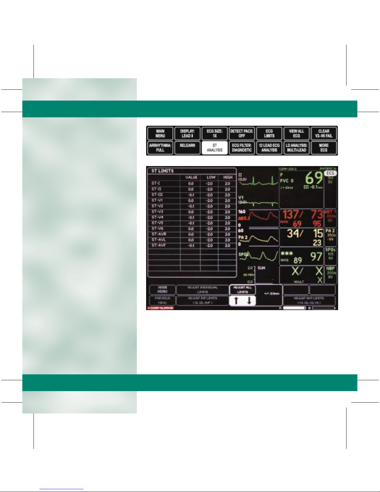
■ ST Limits: Displays a menu
and information window to set
and adjust ST deviation limits.
• To Adjust All ST Limits:
– Select the ECG parameter
window.
– Select ST ANALYSIS.
– Select ADJUST ALL
LIMITS.
– Turn the Trim Knob to the
+ / – desired limit and
press to select.
– All limits are automatically
adjusted in the information
window.
– The monitor adjusts the low
and high limits around the
current value of the lead(s).
– Select MAIN MENU to
exit.
TAB
TRIM
COVER &
NON-TAB
TRIM
COVER &
NON-TAB
TRIM
TAB
TRIM
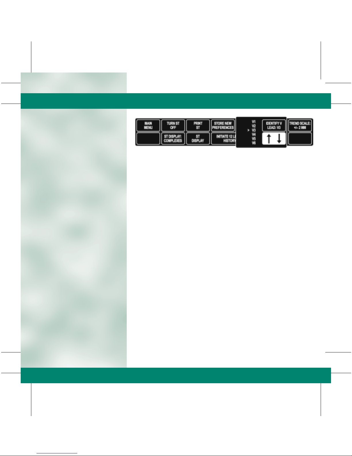
■ Identify V Lead: Identifies the
V Lead being used for ECG and
ST analysis.
• To Change the V Lead:
– Select the ECG parameter
window.
– Select ST ANALYSIS.
– Select IDENTIFY V LEAD.
– Move the cursor in front of
the desired V Lead and
press to select.
NOTE: With a 5-leadwire cable, the V Lead is used in ST
Analysis and arrhythmia analysis.
Changing this label changes the label on the V-lead trend and
complex.
NOTE: With a 10-leadwire cable, the V Lead is used for
arrhythmia analysis only. Changing this label DOES NOT
change the label on the ST display. Use the ST display menu
to change the label.
– Select MAIN MENU to
exit.
TAB
TRIM
COVER &
NON-TAB
TRIM
COVER &
NON-TAB
TRIM
TAB
TRIM
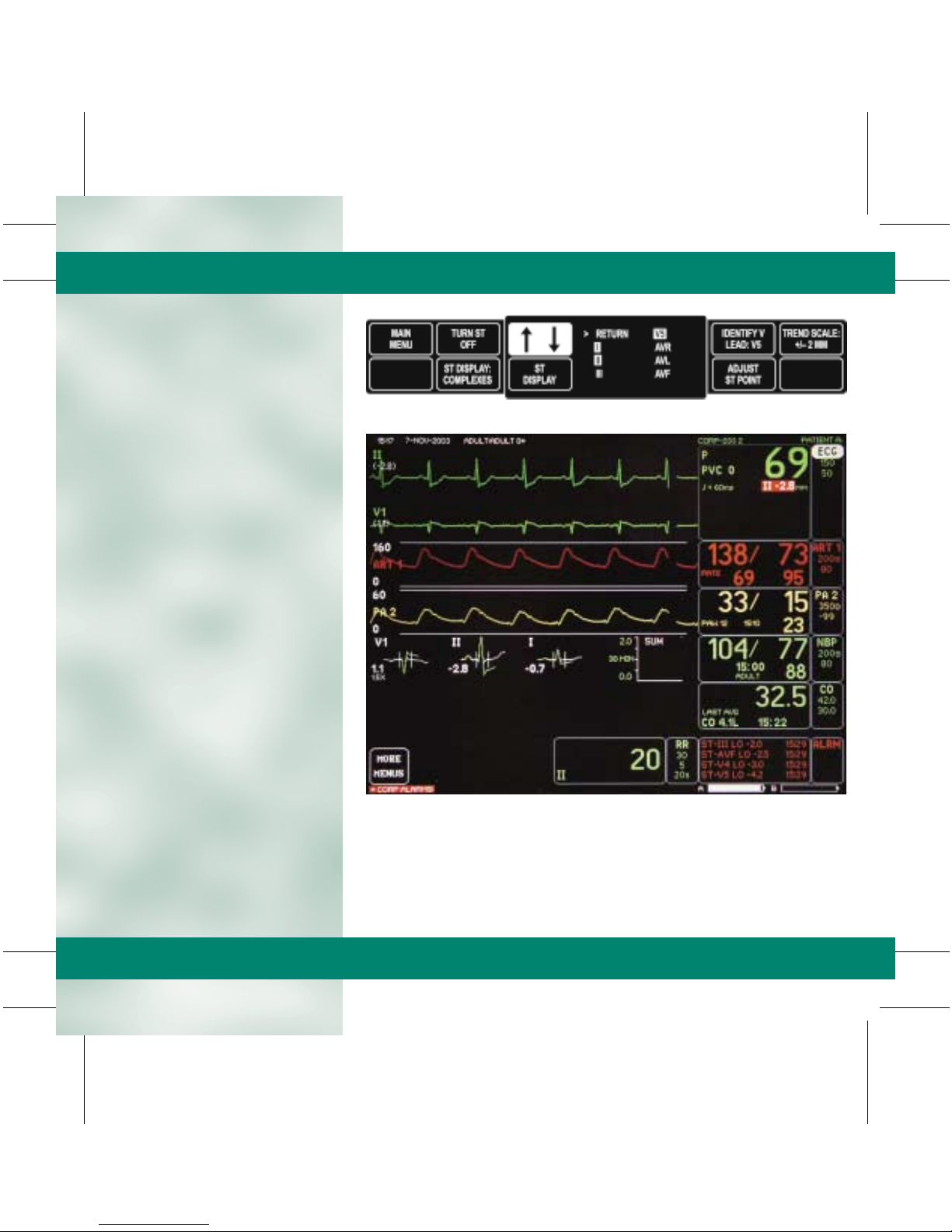
■ ST Display: Changes the leads
for the trends and complexes
display.
• To Change the Displayed ST
Leads:
– Select the ECG parameter
window.
– Select ST ANALYSIS.
– Select ST DISPLAY.
– Turn the Trim Knob to
deselect one of the three
selections before selecting
another.
– Select MAIN MENU to
exit.
NOTE: A maximum of three choices can be selected for the ST
Display.
TAB
TRIM
COVER &
NON-TAB
TRIM
COVER &
NON-TAB
TRIM
TAB
TRIM

TAB
TRIM
COVER &
NON-TAB
TRIM
COVER &
NON-TAB
TRIM
TAB
TRIM
 Loading...