

Page 1
GE Healthcare
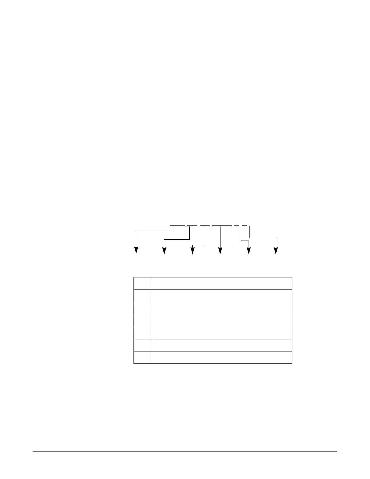
Trim Knob
NBP Go/Stop
Zero All
Silence Alarm/
Admit
Graph
Power
Charging Status
A
B
AC Battery
Dash 3000/4000/5000™ Patient Monitor
Service Manual
Software Version 6.5 or later
Dash 3000/4000/5000
English
2023909-008 (CD)
2023896-100 (paper)
© 2008, 2009 General Electric Company
All Rights Reserved
Page 2

NOTE: The information in this manual only applies to Dash 3000/4000/5000 patient monitors with software version 6.5 or
later. It does not apply to earlier software versions. Due to continuing product innovation, specifications in this manual are
subject to change without notice.
NOTE: The assembly drawings in this manual only support patient monitors with the SD0 product code. Patient monitors with
the SD0 product code are only compatible with software version 6.5 or later.
NOTE: For technical documentation purposes, the abbreviation GE is used for the legal entity name, GE Medical Systems
Information Technologies.
Listed below are GE Medical Systems Information Technologies trademarks. All other trademarks contained herein are the
property of their respective owners.
DASH, DINAMAP, EAGLE, MULTI-LINK, MUSE, SAM, SOLAR, TRIM KNOB, and UNITY NETWORK are trademarks
of GE Medical Systems Information Technologies registered in the United States Patent and Trademark Office.
12SL, CENTRALSCOPE, INTELLIRATE, MENTOR, and SUPERSTAT are trademarks of GE Medical Systems Information
Technologies.
T-2 Dash 3000/4000/5000 2000966-456D
19 October 2009
Page 3

Contents
1 Introduction . . . . . . . . . . . . . . . . . . . . . . . . . . . . . . . . . . . . 1-1
Manual information . . . . . . . . . . . . . . . . . . . . . . . . . . . . . . . . . . . . . . . . . . . . . . . . . . 1-2
Revision history . . . . . . . . . . . . . . . . . . . . . . . . . . . . . . . . . . . . . . . . . . . . . . . . . . .1-2
Manual purpose . . . . . . . . . . . . . . . . . . . . . . . . . . . . . . . . . . . . . . . . . . . . . . . . . . .1-2
Intended audience . . . . . . . . . . . . . . . . . . . . . . . . . . . . . . . . . . . . . . . . . . . . . . . . .1-2
Ordering manuals . . . . . . . . . . . . . . . . . . . . . . . . . . . . . . . . . . . . . . . . . . . . . . . . .1-2
Safety information . . . . . . . . . . . . . . . . . . . . . . . . . . . . . . . . . . . . . . . . . . . . . . . . . . . 1-3
Responsibility of the manufacturer . . . . . . . . . . . . . . . . . . . . . . . . . . . . . . . . . . . . .1-3
General . . . . . . . . . . . . . . . . . . . . . . . . . . . . . . . . . . . . . . . . . . . . . . . . . . . . . . . . .1 -3
Warnings, cautions, and notes . . . . . . . . . . . . . . . . . . . . . . . . . . . . . . . . . . . . . . . .1-4
Equipment symbols . . . . . . . . . . . . . . . . . . . . . . . . . . . . . . . . . . . . . . . . . . . . . . . . . . 1-5
Service information . . . . . . . . . . . . . . . . . . . . . . . . . . . . . . . . . . . . . . . . . . . . . . . . . . 1-8
Service requirements . . . . . . . . . . . . . . . . . . . . . . . . . . . . . . . . . . . . . . . . . . . . . . .1-8
Equipment identification . . . . . . . . . . . . . . . . . . . . . . . . . . . . . . . . . . . . . . . . . . . . .1-8
2 Equipment overview . . . . . . . . . . . . . . . . . . . . . . . . . . . . . 2-1
Components . . . . . . . . . . . . . . . . . . . . . . . . . . . . . . . . . . . . . . . . . . . . . . . . . . . . . . . . 2-2
Monitoring system . . . . . . . . . . . . . . . . . . . . . . . . . . . . . . . . . . . . . . . . . . . . . . . . .2-2
Patient monitor . . . . . . . . . . . . . . . . . . . . . . . . . . . . . . . . . . . . . . . . . . . . . . . . . . . .2-2
Controls and indicators . . . . . . . . . . . . . . . . . . . . . . . . . . . . . . . . . . . . . . . . . . . . .2-5
Exchangeable or compatible battery packs . . . . . . . . . . . . . . . . . . . . . . . . . . . . . . 2-9
Optional components . . . . . . . . . . . . . . . . . . . . . . . . . . . . . . . . . . . . . . . . . . . . . .2-10
Optional remote control . . . . . . . . . . . . . . . . . . . . . . . . . . . . . . . . . . . . . . . . . . . .2-13
Software packages and software options . . . . . . . . . . . . . . . . . . . . . . . . . . . . . . . 2-14
Software packages . . . . . . . . . . . . . . . . . . . . . . . . . . . . . . . . . . . . . . . . . . . . . . .2-14
Software options . . . . . . . . . . . . . . . . . . . . . . . . . . . . . . . . . . . . . . . . . . . . . . . . .2-14
Ethernet communication . . . . . . . . . . . . . . . . . . . . . . . . . . . . . . . . . . . . . . . . . . . . . 2-15
About Ethernet . . . . . . . . . . . . . . . . . . . . . . . . . . . . . . . . . . . . . . . . . . . . . . . . . . .2-15
Twisted pair . . . . . . . . . . . . . . . . . . . . . . . . . . . . . . . . . . . . . . . . . . . . . . . . . . . . .2-15
Network Terms . . . . . . . . . . . . . . . . . . . . . . . . . . . . . . . . . . . . . . . . . . . . . . . . . . .2-16
Theory of operation . . . . . . . . . . . . . . . . . . . . . . . . . . . . . . . . . . . . . . . . . . . . . . . . . 2-17
Components . . . . . . . . . . . . . . . . . . . . . . . . . . . . . . . . . . . . . . . . . . . . . . . . . . . . .2-17
Overall patient monitor block diagram . . . . . . . . . . . . . . . . . . . . . . . . . . . . . . . . .2-17
Power supply . . . . . . . . . . . . . . . . . . . . . . . . . . . . . . . . . . . . . . . . . . . . . . . . . . . .2-18
Data Acquisition System (DAS) . . . . . . . . . . . . . . . . . . . . . . . . . . . . . . . . . . . . . .2-18
2000966-456D Dash 3000/4000/5000 i
Page 4

Processor/power management subsystem . . . . . . . . . . . . . . . . . . . . . . . . . . . . .2-27
Lithium-Ion battery power . . . . . . . . . . . . . . . . . . . . . . . . . . . . . . . . . . . . . . . . . .2-35
Speaker . . . . . . . . . . . . . . . . . . . . . . . . . . . . . . . . . . . . . . . . . . . . . . . . . . . . . . . .2-40
Handle subassembly . . . . . . . . . . . . . . . . . . . . . . . . . . . . . . . . . . . . . . . . . . . . . .2-40
Interfaces . . . . . . . . . . . . . . . . . . . . . . . . . . . . . . . . . . . . . . . . . . . . . . . . . . . . . . .2-40
Storage and backup . . . . . . . . . . . . . . . . . . . . . . . . . . . . . . . . . . . . . . . . . . . . . . .2-42
Optional thermal printer . . . . . . . . . . . . . . . . . . . . . . . . . . . . . . . . . . . . . . . . . . . .2-43
3 Installation . . . . . . . . . . . . . . . . . . . . . . . . . . . . . . . . . . . . . 3-1
Installation overview . . . . . . . . . . . . . . . . . . . . . . . . . . . . . . . . . . . . . . . . . . . . . . . . . 3-2
Inspection . . . . . . . . . . . . . . . . . . . . . . . . . . . . . . . . . . . . . . . . . . . . . . . . . . . . . . . . . . 3-3
Before you begin... . . . . . . . . . . . . . . . . . . . . . . . . . . . . . . . . . . . . . . . . . . . . . . . . . . 3-4
Connections . . . . . . . . . . . . . . . . . . . . . . . . . . . . . . . . . . . . . . . . . . . . . . . . . . . . . . . . 3-5
Back panel connections . . . . . . . . . . . . . . . . . . . . . . . . . . . . . . . . . . . . . . . . . . . . .3-5
Power up . . . . . . . . . . . . . . . . . . . . . . . . . . . . . . . . . . . . . . . . . . . . . . . . . . . . . . . .3-7
Configure . . . . . . . . . . . . . . . . . . . . . . . . . . . . . . . . . . . . . . . . . . . . . . . . . . . . . . . .3-7
Dash installation checkout procedure . . . . . . . . . . . . . . . . . . . . . . . . . . . . . . . . . . . 3-8
4 Configuration . . . . . . . . . . . . . . . . . . . . . . . . . . . . . . . . . . . 4-1
Before you begin... . . . . . . . . . . . . . . . . . . . . . . . . . . . . . . . . . . . . . . . . . . . . . . . . . . 4-2
Service menus . . . . . . . . . . . . . . . . . . . . . . . . . . . . . . . . . . . . . . . . . . . . . . . . . . . . . . 4-3
Boot Loader Service Menu . . . . . . . . . . . . . . . . . . . . . . . . . . . . . . . . . . . . . . . . . .4-4
Main menu service mode . . . . . . . . . . . . . . . . . . . . . . . . . . . . . . . . . . . . . . . . . . . .4-5
Procedures . . . . . . . . . . . . . . . . . . . . . . . . . . . . . . . . . . . . . . . . . . . . . . . . . . . . . . . . . 4-9
Set print locations . . . . . . . . . . . . . . . . . . . . . . . . . . . . . . . . . . . . . . . . . . . . . . . . . . 4-10
Service Mode settings . . . . . . . . . . . . . . . . . . . . . . . . . . . . . . . . . . . . . . . . . . . . . . . 4-11
Set Unit Name . . . . . . . . . . . . . . . . . . . . . . . . . . . . . . . . . . . . . . . . . . . . . . . . . . .4-11
Set Bed Number . . . . . . . . . . . . . . . . . . . . . . . . . . . . . . . . . . . . . . . . . . . . . . . . .4-11
Patient-Monitor Type . . . . . . . . . . . . . . . . . . . . . . . . . . . . . . . . . . . . . . . . . . . . . .4-11
Admit Menu . . . . . . . . . . . . . . . . . . . . . . . . . . . . . . . . . . . . . . . . . . . . . . . . . . . . .4-13
Confirm or configure wireless LAN . . . . . . . . . . . . . . . . . . . . . . . . . . . . . . . . . . .4-14
Boot Code settings . . . . . . . . . . . . . . . . . . . . . . . . . . . . . . . . . . . . . . . . . . . . . . . . . 4-16
Set Defib Sync Voltage and pulse width . . . . . . . . . . . . . . . . . . . . . . . . . . . . . . .4-16
Set Line Frequency . . . . . . . . . . . . . . . . . . . . . . . . . . . . . . . . . . . . . . . . . . . . . . .4-16
Set CIC and QS protocol . . . . . . . . . . . . . . . . . . . . . . . . . . . . . . . . . . . . . . . . . . .4-17
Set MUSE system protocol . . . . . . . . . . . . . . . . . . . . . . . . . . . . . . . . . . . . . . . . .4-17
ii Dash 3000/4000/5000 2000966-456D
Page 5

Transcutaneous Pace Blank Length . . . . . . . . . . . . . . . . . . . . . . . . . . . . . . . . . .4-17
Set Country Selection . . . . . . . . . . . . . . . . . . . . . . . . . . . . . . . . . . . . . . . . . . . . .4-18
Set Language . . . . . . . . . . . . . . . . . . . . . . . . . . . . . . . . . . . . . . . . . . . . . . . . . . . .4-18
Enable or disable AFIB Identification . . . . . . . . . . . . . . . . . . . . . . . . . . . . . . . . . .4-19
Enable or disable IntelliRate . . . . . . . . . . . . . . . . . . . . . . . . . . . . . . . . . . . . . . . .4-19
Analog Out Buzz . . . . . . . . . . . . . . . . . . . . . . . . . . . . . . . . . . . . . . . . . . . . . . . . .4-20
Completion . . . . . . . . . . . . . . . . . . . . . . . . . . . . . . . . . . . . . . . . . . . . . . . . . . . . . .4-20
Advanced user procedures . . . . . . . . . . . . . . . . . . . . . . . . . . . . . . . . . . . . . . . . . . . 4-21
Procedures . . . . . . . . . . . . . . . . . . . . . . . . . . . . . . . . . . . . . . . . . . . . . . . . . . . . . .4-21
Set time and date . . . . . . . . . . . . . . . . . . . . . . . . . . . . . . . . . . . . . . . . . . . . . . . . .4-21
Transfer monitor defaults . . . . . . . . . . . . . . . . . . . . . . . . . . . . . . . . . . . . . . . . . . .4-22
5 Preventive maintenance . . . . . . . . . . . . . . . . . . . . . . . . . . 5-1
Maintenance schedule . . . . . . . . . . . . . . . . . . . . . . . . . . . . . . . . . . . . . . . . . . . . . . . . 5-2
Visual inspection . . . . . . . . . . . . . . . . . . . . . . . . . . . . . . . . . . . . . . . . . . . . . . . . . . . . 5-3
Cleaning and disinfecting the patient monitor . . . . . . . . . . . . . . . . . . . . . . . . . . . . 5-3
Procedure . . . . . . . . . . . . . . . . . . . . . . . . . . . . . . . . . . . . . . . . . . . . . . . . . . . . . . .5-3
Cautions . . . . . . . . . . . . . . . . . . . . . . . . . . . . . . . . . . . . . . . . . . . . . . . . . . . . . . . . .5-4
Impact or results of improper cleaning products and processes . . . . . . . . . . . . . .5-5
Cleaning products to avoid . . . . . . . . . . . . . . . . . . . . . . . . . . . . . . . . . . . . . . . . . .5-5
Storage . . . . . . . . . . . . . . . . . . . . . . . . . . . . . . . . . . . . . . . . . . . . . . . . . . . . . . . . .5-5
Clean the print head . . . . . . . . . . . . . . . . . . . . . . . . . . . . . . . . . . . . . . . . . . . . . . . .5-6
Cleaning, disinfecting and storing GE ECG cables and leadwires . . . . . . . . . . . . 5-7
Cleaning and disinfecting . . . . . . . . . . . . . . . . . . . . . . . . . . . . . . . . . . . . . . . . . . . .5-7
Sterilization . . . . . . . . . . . . . . . . . . . . . . . . . . . . . . . . . . . . . . . . . . . . . . . . . . . . . .5-8
Cautions . . . . . . . . . . . . . . . . . . . . . . . . . . . . . . . . . . . . . . . . . . . . . . . . . . . . . . . . .5-8
Storage . . . . . . . . . . . . . . . . . . . . . . . . . . . . . . . . . . . . . . . . . . . . . . . . . . . . . . . . .5-8
Improper cleaning products and processes impact or results . . . . . . . . . . . . . . . .5-8
Cleaning products to avoid . . . . . . . . . . . . . . . . . . . . . . . . . . . . . . . . . . . . . . . . . .5-9
Cleaning other applied parts . . . . . . . . . . . . . . . . . . . . . . . . . . . . . . . . . . . . . . . . . . 5-9
Battery maintenance . . . . . . . . . . . . . . . . . . . . . . . . . . . . . . . . . . . . . . . . . . . . . . . . 5-10
How to charge the battery . . . . . . . . . . . . . . . . . . . . . . . . . . . . . . . . . . . . . . . . . .5-10
How to condition the battery . . . . . . . . . . . . . . . . . . . . . . . . . . . . . . . . . . . . . . . .5-10
How to store the battery . . . . . . . . . . . . . . . . . . . . . . . . . . . . . . . . . . . . . . . . . . . .5-12
How to wake up the battery . . . . . . . . . . . . . . . . . . . . . . . . . . . . . . . . . . . . . . . . .5-12
How to replace the batteries . . . . . . . . . . . . . . . . . . . . . . . . . . . . . . . . . . . . . . . .5-14
Rechargeable battery recycling . . . . . . . . . . . . . . . . . . . . . . . . . . . . . . . . . . . . . .5-14
About the Cadex SMart Two+ charger . . . . . . . . . . . . . . . . . . . . . . . . . . . . . . . . .5-15
Clear the stored patient data memory . . . . . . . . . . . . . . . . . . . . . . . . . . . . . . . . . . 5-16
2000966-456D Dash 3000/4000/5000 iii
Page 6

6 Troubleshooting . . . . . . . . . . . . . . . . . . . . . . . . . . . . . . . . 6-1
Fault analysis . . . . . . . . . . . . . . . . . . . . . . . . . . . . . . . . . . . . . . . . . . . . . . . . . . . . . . . 6-2
Overview . . . . . . . . . . . . . . . . . . . . . . . . . . . . . . . . . . . . . . . . . . . . . . . . . . . . . . . .6-2
Required tools or equipment . . . . . . . . . . . . . . . . . . . . . . . . . . . . . . . . . . . . . . . . .6-2
Problems . . . . . . . . . . . . . . . . . . . . . . . . . . . . . . . . . . . . . . . . . . . . . . . . . . . . . . . .6-2
Acquisition PCB symptoms . . . . . . . . . . . . . . . . . . . . . . . . . . . . . . . . . . . . . . . . . .6-4
Processor PCB symptoms . . . . . . . . . . . . . . . . . . . . . . . . . . . . . . . . . . . . . . . . . . .6-4
Error messages . . . . . . . . . . . . . . . . . . . . . . . . . . . . . . . . . . . . . . . . . . . . . . . . . . . . . 6-5
Battery alarms and messages . . . . . . . . . . . . . . . . . . . . . . . . . . . . . . . . . . . . . . . . . 6-7
Battery messages displayed in the ECG waveform area . . . . . . . . . . . . . . . . . . . .6-7
Battery messages displayed in the Battery Status information window . . . . . . . . .6-8
Battery Messages Displayed in the Battery Fuel Gauge Icon . . . . . . . . . . . . . . . .6-8
Writer or printer . . . . . . . . . . . . . . . . . . . . . . . . . . . . . . . . . . . . . . . . . . . . . . . . . . . . . 6-9
External . . . . . . . . . . . . . . . . . . . . . . . . . . . . . . . . . . . . . . . . . . . . . . . . . . . . . . . . .6-9
Internal . . . . . . . . . . . . . . . . . . . . . . . . . . . . . . . . . . . . . . . . . . . . . . . . . . . . . . . . . .6-9
No waveform at central station . . . . . . . . . . . . . . . . . . . . . . . . . . . . . . . . . . . . . . . 6-10
Monitor defaults transfer . . . . . . . . . . . . . . . . . . . . . . . . . . . . . . . . . . . . . . . . . . . . 6-11
Storing monitor defaults . . . . . . . . . . . . . . . . . . . . . . . . . . . . . . . . . . . . . . . . . . . .6-11
Copying stored monitor defaults . . . . . . . . . . . . . . . . . . . . . . . . . . . . . . . . . . . . .6-11
Change internet address . . . . . . . . . . . . . . . . . . . . . . . . . . . . . . . . . . . . . . . . . . . . . 6-12
Review errors . . . . . . . . . . . . . . . . . . . . . . . . . . . . . . . . . . . . . . . . . . . . . . . . . . . . . . 6-13
View output or input errors . . . . . . . . . . . . . . . . . . . . . . . . . . . . . . . . . . . . . . . . . .6-13
Useful error data . . . . . . . . . . . . . . . . . . . . . . . . . . . . . . . . . . . . . . . . . . . . . . . . .6-14
Get error logs . . . . . . . . . . . . . . . . . . . . . . . . . . . . . . . . . . . . . . . . . . . . . . . . . . . . . . 6-16
Get logs via PC using netUpdate . . . . . . . . . . . . . . . . . . . . . . . . . . . . . . . . . . . . .6-16
Get logs via CIC . . . . . . . . . . . . . . . . . . . . . . . . . . . . . . . . . . . . . . . . . . . . . . . . . .6-21
Get logs via Centralscope . . . . . . . . . . . . . . . . . . . . . . . . . . . . . . . . . . . . . . . . . .6-21
Wireless LAN . . . . . . . . . . . . . . . . . . . . . . . . . . . . . . . . . . . . . . . . . . . . . . . . . . . . . . 6-24
Access Service Mode . . . . . . . . . . . . . . . . . . . . . . . . . . . . . . . . . . . . . . . . . . . . .6-24
Identify the wireless technology . . . . . . . . . . . . . . . . . . . . . . . . . . . . . . . . . . . . . .6-24
802.11b . . . . . . . . . . . . . . . . . . . . . . . . . . . . . . . . . . . . . . . . . . . . . . . . . . . . . . . .6-26
802.11 . . . . . . . . . . . . . . . . . . . . . . . . . . . . . . . . . . . . . . . . . . . . . . . . . . . . . . . . .6-29
7 Field replaceable units . . . . . . . . . . . . . . . . . . . . . . . . . . . 7-1
Ordering field replaceable units . . . . . . . . . . . . . . . . . . . . . . . . . . . . . . . . . . . . . . . . 7-2
Field replaceable units . . . . . . . . . . . . . . . . . . . . . . . . . . . . . . . . . . . . . . . . . . . . . . . 7-3
iv Dash 3000/4000/5000 2000966-456D
Page 7

Disassembly guidelines . . . . . . . . . . . . . . . . . . . . . . . . . . . . . . . . . . . . . . . . . . . . . . 7-7
Tools required . . . . . . . . . . . . . . . . . . . . . . . . . . . . . . . . . . . . . . . . . . . . . . . . . . . .7-7
Before disassembly . . . . . . . . . . . . . . . . . . . . . . . . . . . . . . . . . . . . . . . . . . . . . . . .7-7
Hardware precautions . . . . . . . . . . . . . . . . . . . . . . . . . . . . . . . . . . . . . . . . . . . . . .7-8
Electrostatic discharge (ESD) precautions . . . . . . . . . . . . . . . . . . . . . . . . . . . . . .7-8
Remove or replace handle assembly . . . . . . . . . . . . . . . . . . . . . . . . . . . . . . . . . . . . 7-9
Remove or replace display assembly . . . . . . . . . . . . . . . . . . . . . . . . . . . . . . . . . . 7-12
Replace display flex assembly . . . . . . . . . . . . . . . . . . . . . . . . . . . . . . . . . . . . . . . . 7-18
Replace display assembly parts . . . . . . . . . . . . . . . . . . . . . . . . . . . . . . . . . . . . . . . 7-20
Open display assembly . . . . . . . . . . . . . . . . . . . . . . . . . . . . . . . . . . . . . . . . . . . .7-21
Replace Dash 4000/5000 alarm light . . . . . . . . . . . . . . . . . . . . . . . . . . . . . . . . . .7-22
Replace display inverter . . . . . . . . . . . . . . . . . . . . . . . . . . . . . . . . . . . . . . . . . . . .7-23
Replace keypad assembly or Trim Knob control . . . . . . . . . . . . . . . . . . . . . . . . .7-24
Replace display components without LCD . . . . . . . . . . . . . . . . . . . . . . . . . . . . .7-25
Replace main unit parts . . . . . . . . . . . . . . . . . . . . . . . . . . . . . . . . . . . . . . . . . . . . . 7-28
Replace DAS assembly . . . . . . . . . . . . . . . . . . . . . . . . . . . . . . . . . . . . . . . . . . . .7-28
Replace wireless card . . . . . . . . . . . . . . . . . . . . . . . . . . . . . . . . . . . . . . . . . . . . .7-32
Replace NBP pump assembly . . . . . . . . . . . . . . . . . . . . . . . . . . . . . . . . . . . . . . .7-33
Replace writer assembly or writer flex . . . . . . . . . . . . . . . . . . . . . . . . . . . . . . . . .7-34
Replace speaker assembly . . . . . . . . . . . . . . . . . . . . . . . . . . . . . . . . . . . . . . . . .7-35
Replace CPU/battery housing assembly . . . . . . . . . . . . . . . . . . . . . . . . . . . . . . .7-37
Replace power supply assembly . . . . . . . . . . . . . . . . . . . . . . . . . . . . . . . . . . . . .7-40
Replace battery door . . . . . . . . . . . . . . . . . . . . . . . . . . . . . . . . . . . . . . . . . . . . . . . . 7-42
Replace foot . . . . . . . . . . . . . . . . . . . . . . . . . . . . . . . . . . . . . . . . . . . . . . . . . . . . . . . 7-43
Replace writer cover . . . . . . . . . . . . . . . . . . . . . . . . . . . . . . . . . . . . . . . . . . . . . . . . 7-44
Recommended checkout . . . . . . . . . . . . . . . . . . . . . . . . . . . . . . . . . . . . . . . . . . . . 7-45
8 Functional and electrical safety checks . . . . . . . . . . . . . 8-1
Overview . . . . . . . . . . . . . . . . . . . . . . . . . . . . . . . . . . . . . . . . . . . . . . . . . . . . . . . . . . . 8-2
Manufacturer recommendations . . . . . . . . . . . . . . . . . . . . . . . . . . . . . . . . . . . . . .8-2
Frequency . . . . . . . . . . . . . . . . . . . . . . . . . . . . . . . . . . . . . . . . . . . . . . . . . . . . . . .8-2
Test equipment . . . . . . . . . . . . . . . . . . . . . . . . . . . . . . . . . . . . . . . . . . . . . . . . . . .8 -2
Functional Checkout procedures . . . . . . . . . . . . . . . . . . . . . . . . . . . . . . . . . . . . . .8-3
Electrical safety tests . . . . . . . . . . . . . . . . . . . . . . . . . . . . . . . . . . . . . . . . . . . . . . . . 8-4
General . . . . . . . . . . . . . . . . . . . . . . . . . . . . . . . . . . . . . . . . . . . . . . . . . . . . . . . . .8 -4
Recommendations . . . . . . . . . . . . . . . . . . . . . . . . . . . . . . . . . . . . . . . . . . . . . . . . .8-4
Power outlet test . . . . . . . . . . . . . . . . . . . . . . . . . . . . . . . . . . . . . . . . . . . . . . . . . .8-5
Power cord and plug . . . . . . . . . . . . . . . . . . . . . . . . . . . . . . . . . . . . . . . . . . . . . . .8-5
Ground (earth) integrity . . . . . . . . . . . . . . . . . . . . . . . . . . . . . . . . . . . . . . . . . . . . .8-6
2000966-456D Dash 3000/4000/5000 v
Page 8

Ground (earth) wire leakage current tests . . . . . . . . . . . . . . . . . . . . . . . . . . . . . . .8-8
Enclosure (Touch) leakage current test . . . . . . . . . . . . . . . . . . . . . . . . . . . . . . . . .8-9
Patient (source) leakage current test . . . . . . . . . . . . . . . . . . . . . . . . . . . . . . . . . .8-12
Patient (sink) leakage current test (mains voltage on the applied part) . . . . . . . .8-14
BISx (option) current leakage tests . . . . . . . . . . . . . . . . . . . . . . . . . . . . . . . . . . . . 8-16
BISx patient (source) leakage current test . . . . . . . . . . . . . . . . . . . . . . . . . . . . . .8-16
BISx patient (sink) leakage current test . . . . . . . . . . . . . . . . . . . . . . . . . . . . . . . .8-18
Test completion . . . . . . . . . . . . . . . . . . . . . . . . . . . . . . . . . . . . . . . . . . . . . . . . . .8-19
Functional Checkout procedures . . . . . . . . . . . . . . . . . . . . . . . . . . . . . . . . . . . . . . 8-20
Frequency . . . . . . . . . . . . . . . . . . . . . . . . . . . . . . . . . . . . . . . . . . . . . . . . . . . . . .8-20
Identify enabled patient parameters and software options . . . . . . . . . . . . . . . . .8-20
Patient monitor power-up tests . . . . . . . . . . . . . . . . . . . . . . . . . . . . . . . . . . . . . .8-21
ECG tests . . . . . . . . . . . . . . . . . . . . . . . . . . . . . . . . . . . . . . . . . . . . . . . . . . . . . . .8-22
Respiration tests . . . . . . . . . . . . . . . . . . . . . . . . . . . . . . . . . . . . . . . . . . . . . . . . .8-25
Temperature tests . . . . . . . . . . . . . . . . . . . . . . . . . . . . . . . . . . . . . . . . . . . . . . . .8-26
Cardiac output tests (option) . . . . . . . . . . . . . . . . . . . . . . . . . . . . . . . . . . . . . . . .8-27
Invasive blood pressure tests (option) . . . . . . . . . . . . . . . . . . . . . . . . . . . . . . . . .8-27
Pulse oximetry tests for GE Ohmeda SPO2 oximeter . . . . . . . . . . . . . . . . . . . . .8-31
Pulse oximetry tests for Masimo SET SPO2 . . . . . . . . . . . . . . . . . . . . . . . . . . . .8-33
Pulse oximetry tests for Nellcor OxiMax SPO2 . . . . . . . . . . . . . . . . . . . . . . . . . .8-35
Noninvasive blood pressure tests . . . . . . . . . . . . . . . . . . . . . . . . . . . . . . . . . . . .8-37
NBP calibration . . . . . . . . . . . . . . . . . . . . . . . . . . . . . . . . . . . . . . . . . . . . . . . . . .8-39
Analog output and defibrillator synchronization tests . . . . . . . . . . . . . . . . . . . . . .8-42
End-tidal CO
Battery tests . . . . . . . . . . . . . . . . . . . . . . . . . . . . . . . . . . . . . . . . . . . . . . . . . . . . .8-46
Graph or print tests (option) . . . . . . . . . . . . . . . . . . . . . . . . . . . . . . . . . . . . . . . . .8-46
Display test . . . . . . . . . . . . . . . . . . . . . . . . . . . . . . . . . . . . . . . . . . . . . . . . . . . . .8-47
Speaker test . . . . . . . . . . . . . . . . . . . . . . . . . . . . . . . . . . . . . . . . . . . . . . . . . . . . .8-47
Network test (option) . . . . . . . . . . . . . . . . . . . . . . . . . . . . . . . . . . . . . . . . . . . . . .8-48
Remote control test (option) . . . . . . . . . . . . . . . . . . . . . . . . . . . . . . . . . . . . . . . . .8-48
BISx test (option) . . . . . . . . . . . . . . . . . . . . . . . . . . . . . . . . . . . . . . . . . . . . . . . . .8-49
Wireless LAN test (option) . . . . . . . . . . . . . . . . . . . . . . . . . . . . . . . . . . . . . . . . . .8-51
Dash Port 2 docking station test (option) . . . . . . . . . . . . . . . . . . . . . . . . . . . . . . .8-53
TRAM-rac 2A module housing peripheral device test (option) . . . . . . . . . . . . . .8-53
ICG Module test (option) . . . . . . . . . . . . . . . . . . . . . . . . . . . . . . . . . . . . . . . . . . .8-53
test (option) . . . . . . . . . . . . . . . . . . . . . . . . . . . . . . . . . . . . . . . . . .8-46
2
Checkout procedures completion . . . . . . . . . . . . . . . . . . . . . . . . . . . . . . . . . . . . . 8-54
A Electromagnetic compatibility (EMC) . . . . . . . . . . . . . . . . .A-1
Electromagnetic Compatibility (EMC) . . . . . . . . . . . . . . . . . . . . . . . . . . . . . . . . . . . A-2
Guidance and Manufacturer’s Declaration – Electromagnetic Emissions . . . . . . .A-2
Guidance and manufacturer’s declaration – electromagnetic immunity . . . . . . . .A-3
Guidance and Manufacturer’s Declaration – Electromagnetic Immunity . . . . . . . .A-4
Recommended separation distances . . . . . . . . . . . . . . . . . . . . . . . . . . . . . . . . . . .A-5
Compliant cables and accessories . . . . . . . . . . . . . . . . . . . . . . . . . . . . . . . . . . . .A-6
vi Dash 3000/4000/5000 2000966-456D
Page 9

B Network troubleshooting . . . . . . . . . . . . . . . . . . . . . . . . . . .B-1
Network traffic . . . . . . . . . . . . . . . . . . . . . . . . . . . . . . . . . . . . . . . . . . . . . . . . . . . . . . B-2
Traffic types . . . . . . . . . . . . . . . . . . . . . . . . . . . . . . . . . . . . . . . . . . . . . . . . . . . . . .B-2
Flow . . . . . . . . . . . . . . . . . . . . . . . . . . . . . . . . . . . . . . . . . . . . . . . . . . . . . . . . . . . .B-2
Problem: No waveforms or parameters are displayed at the CIC Pro center . . . B-3
C Checklist . . . . . . . . . . . . . . . . . . . . . . . . . . . . . . . . . . . . . . . .C-1
Checklist . . . . . . . . . . . . . . . . . . . . . . . . . . . . . . . . . . . . . . . . . . . . . . . . . . . . . . . . . . . C-2
2000966-456D Dash 3000/4000/5000 vii
Page 10

viii Dash 3000/4000/5000 2000966-456D
Page 11

1 Introduction
2000966-456D Dash 3000/4000/5000 1-1
Page 12

Manual information
Revision history
Each page of this manual has the document part number and revision letter at the
bottom of the page. The revision letter identifies the document’s update level. The
revision history of this document is summarized below.
Revision Comment
Manual purpose
Introduction: Manual information
A Initial release of this manual.
B Updated electrical safety tests and software release content.
C Updated Appendix B.
D Added Appendix for network troubleshooting.
Intended audience
Ordering manuals
This manual supplies technical information for service representatives and technical
personnel so they can maintain the equipment to the assembly level. Use it as a
guide for maintenance and electrical repairs considered field repairable. Where
necessary the manual identifies additional sources of relevant information and
technical assistance.
See the operator’s manual for the instructions necessary to operate the equipment
safely in accordance with its function and intended use.
This manual is intended for service representatives and technical personnel who
maintain, troubleshoot, or repair this equipment.
A paper copy of this manual will be provided upon request. Contact your local GE
representative and request the part number on the first page of the manual.
1-2 Dash 3000/4000/5000 2000966-456D
Page 13

Introduction: Safety information
Safety information
Responsibility of the manufacturer
GE is responsible for the effects of safety, reliability, and performance only if:
Assembly operations, extensions, readjustments, modifications, or repairs are
carried out by persons authorized by GE.
The electrical installation of the relevant room complies with the requirements
of the appropriate regulations.
The equipment is used in accordance with the instructions for use.
General
This device is intended for use under the direct supervision of a licensed health care
practitioner.
This device is not intended for home use.
Federal law restricts this device to be sold by or on the order of a physician.
Contact GE for information before connecting any devices to the equipment that are
not recommended in this manual.
Parts and accessories used must meet the requirements of the applicable IEC 60601
series safety standards, and/or the system configuration must meet the requirements
of the IEC 60601-1-1 medical electrical systems standard.
Periodically, and whenever the integrity of the device is in doubt, test all functions.
The use of accessory equipment not complying with the equivalent safety
requirements of this equipment may lead to a reduced level of safety of the resulting
system. Consideration relating to the choice shall include:
use of the accessory in the patient vicinity; and
evidence that the safety certification of the accessory has been performed in
accordance to the appropriate IEC 60601-1 and/or IEC 60601-1-1 harmonized
national standard.
If the installation of the equipment, in the USA, will use 240V rather than 120V, the
source must be a center-tapped, 240V, single-phase circuit.
2000966-456D Dash 3000/4000/5000 1-3
Page 14

Introduction: Safety information
Warnings, cautions, and notes
The terms danger, warning, and caution are used throughout this manual to point out
hazards and to designate a degree or level or seriousness. Familiarize yourself with
their definitions and significance.
Hazard is defined as a source of potential injury to a person.
DANGER indicates an imminent hazard which, if not avoided, will result in death
or serious injury.
WARNING indicates a potential hazard or unsafe practice which, if not avoided,
could result in death or serious injury.
CAUTION indicates a potential hazard or unsafe practice which, if not avoided,
could result in minor personal injury or product/property damage.
NOTE provides application tips or other useful information to assure that you get
the most from your equipment.
1-4 Dash 3000/4000/5000 2000966-456D
Page 15
Equipment symbols
NOTE: Some symbols may not appear on all equipment.
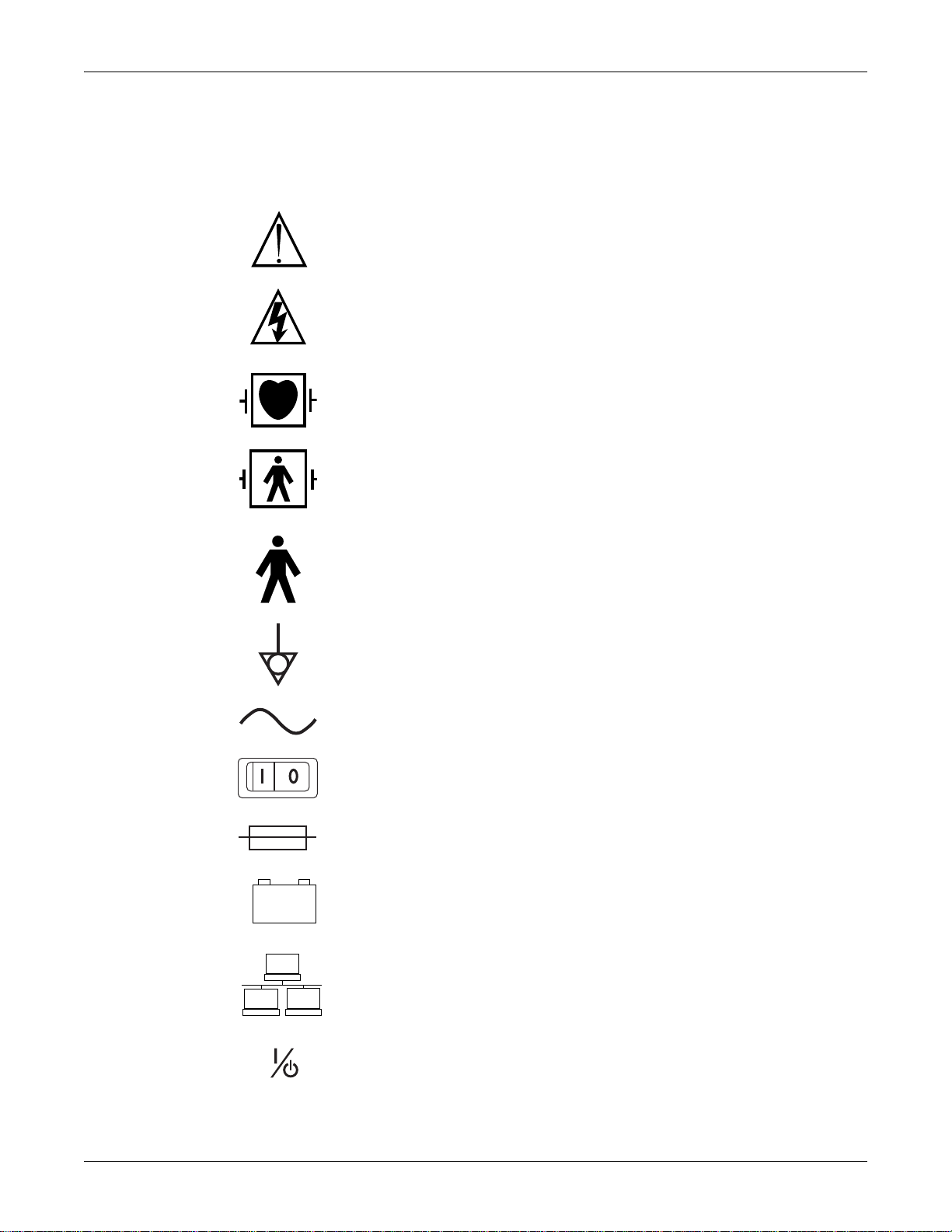
ATTENTION: Consult accompanying documents before using the equipment.
In Europe, this symbol means dangerous or high voltage. In the United States, this symbol
represents the caution notice below:
To reduce the risk of electric shock, do not remove cover (or back). Refer servicing to
qualified personnel.
Defibrillator-proof type CF equipment; type CF equipment is specifically designed for
applications where a conductive connection directly to the heart is established. The paddles
indicate the equipment is defibrillator proof.
Defibrillator-proof type BF equipment; type BF equipment is suitable for intentional external
and internal application to the patient, excluding direct cardiac application. Type BF
equipment is type B equipment with an F-type isolated (floating) part. The paddles indicate
the equipment is defibrillator proof.
Introduction: Equipment symbols
Type B equipment; type B equipment is suitable for intentional external and internal
application to the patient, excluding direct cardiac application.
Equipotential Stud: A ground wire from another device can be tied here to ensure the
devices share a common reference.
Alternating current (AC)
Power;
I = ON; O= OFF
Fuse
Battery
Indicates the Ethernet connection for the patient monitor.
POWER (Dash 3000/4000)
2000966-456D Dash 3000/4000/5000 1-5
Page 16
Introduction: Equipment symbols
4P41
2005-08
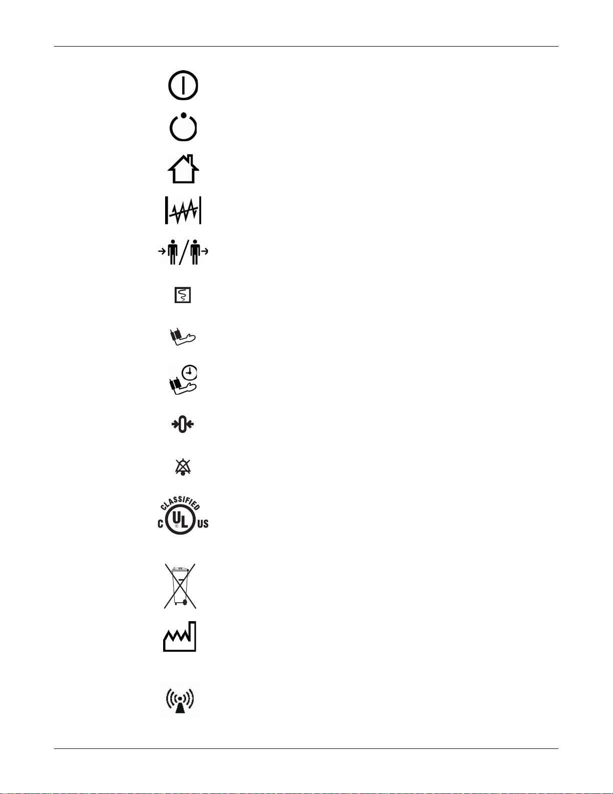
Power (Dash 5000)
Standby (Dash 5000)
Main Display (Dash 5000)
Trend (Dash 5000)
Admit/Discharge (Dash 5000)
Print (Graph Go/Stop on older Dash 3000/4000)
NBP Go/Stop (on older Dash 3000/4000)
NBP Auto (Dash 5000)
Zero All
Silence Alarm/Admit
Medical Equipment
With respect to electric shock, fire and mechanical hazards only in accordance with UL
60601-1, CAN/CSA C22.2 NO. 601, IEC 60601-1, IEC 60601-2-27, IEC 60601-2-30, IEC
60601-2-34, and IEC 60601-2-49.
This symbol indicates that the waste of electrical and electronic equipment must not be
disposed as unsorted municipal waste and must be collected separately. Please contact an
authorized representative of the manufacturer for information concerning the
decommissioning of your equipment.
This symbol indicates the date of manufacture of this device. The first four digits identify the
year and the last two digits identify the month.
Non-ionizing electromagnetic radiation: To indicate elevated, potentially dangerous, levels
of non-ionizing radiation. Note - In case of application in a warning sign the rules according
to ISO 3864-1 shall be adhered to.
IEC 60878 note: See safety sign ISO 7010 - W005 “Warning, non-ionizing radiation”.
1-6 Dash 3000/4000/5000 2000966-456D
Page 17
Introduction: Equipment symbols
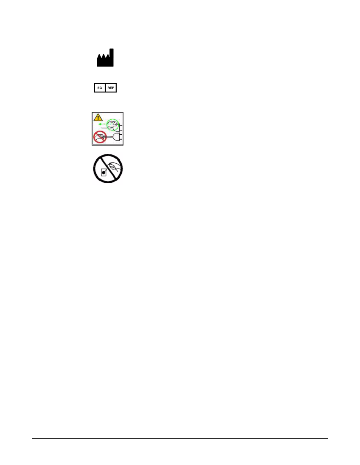
Manufacturer name and address.
European authorized representative.
CAUTION — Safety ground precaution. Remove power cord from the mains source by
grasping the plug. Do not pull on the cable.
2000966-456D Dash 3000/4000/5000 1-7
Page 18
Service information
### ## ## #### # #
ABCDEF
Service requirements
Follow the service requirements listed below.
Refer equipment servicing to GE-authorized service personnel only.
Any unauthorized attempt to repair equipment under warranty voids that
It is the user’s responsibility to report the need for service to GE or to one of
Failure on the part of the responsible individual, hospital, or institution using
Regular maintenance, irrespective of usage, is essential to ensure that the
Equipment identification
Introduction: Service information
warranty.
their authorized agents.
this equipment to implement a satisfactory maintenance schedule may cause
undue equipment failure and possible health hazards.
equipment will always be functional when required.
Every GE device has a unique serial number for identification. A sample of the
information found on a serial number label is shown below.
Description
A
product code
B year manufactured
C fiscal week manufactured
D production sequence number
E manufacturing site
F miscellaneous characteristic
1. The current Dash patient monitor product code is SD0.
1
NOTE
Dash 3000/4000/5000 patient monitors with the SD0 product
code are only compatible with software version 6.5 or later.
1-8 Dash 3000/4000/5000 2000966-456D
Page 19

2 Equipment overview
2000966-456D Dash 3000/4000/5000 2-1
Page 20
Components
Trim Knob
NBP Go/Stop
Zero All
Silence Alarm/
Admit
Graph
Power
Charging Status
A
B
AC Battery
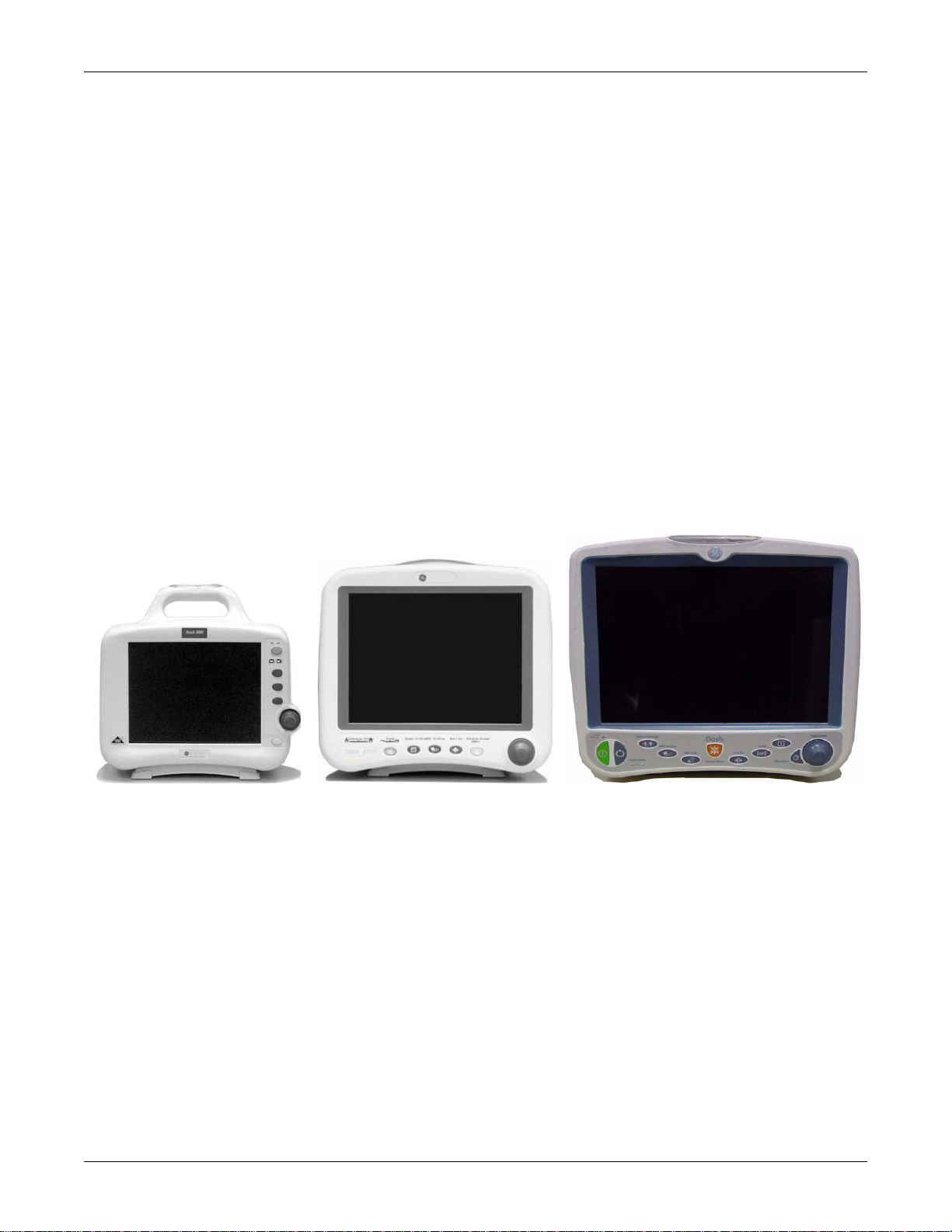
Dash 4000 monitorDash 3000 monitor
001C 051D 003A
Dash 5000 monitor
Monitoring system
Patient monitor
Equipment overview: Components
The Dash patient monitor can function as a portable monitoring device with a builtin writer, or as a flexible care monitoring device connected to the optional Unity
Network™ via Ethernet. If using the wireless card or Ethernet connection, optional
components are a Clinical Information Center (CIC Pro™) and a Centralscope™
central station.
This device is designed to monitor a fixed set of parameters including ECG,
noninvasive blood pressure, impedance respiration, SpO2, and temperature.
Invasive pressure, BISx, and EtCO2 are optional features. Additional specialized
features include cardiac output, cardiac calculations, pulmonary calculations, dose
calculations, PA wedge (PA wedge is only available with the invasive pressure
option), ICG module interface, and SAM™ module interface.
NOTE
For compatibility information, contact Technical Support.
2-2 Dash 3000/4000/5000 2000966-456D
Page 21
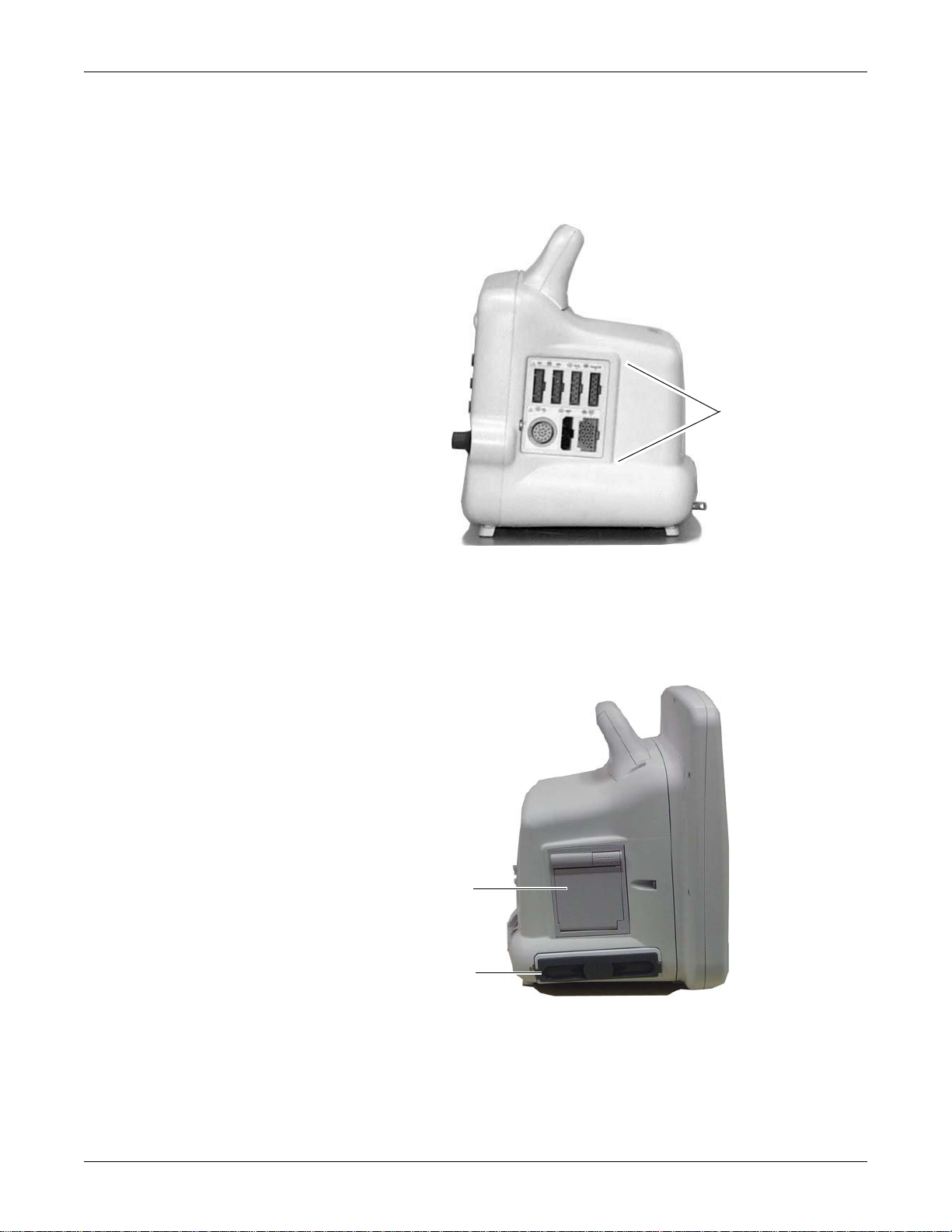
Right side view
Patient cable
connectors
002A
925B
A
B
Equipment overview: Components
All of the patient cable connectors are located on the right side of the patient
monitor. A Trim Knob™ control provides single control operation of virtually all
patient monitor functions.
Left side view
On the left of the patient monitor, you can find the built-in writer and the battery
compartment.
2000966-456D Dash 3000/4000/5000 2-3
Page 22
Equipment overview: Components
004A
A
B
HGFEDC
Name Description
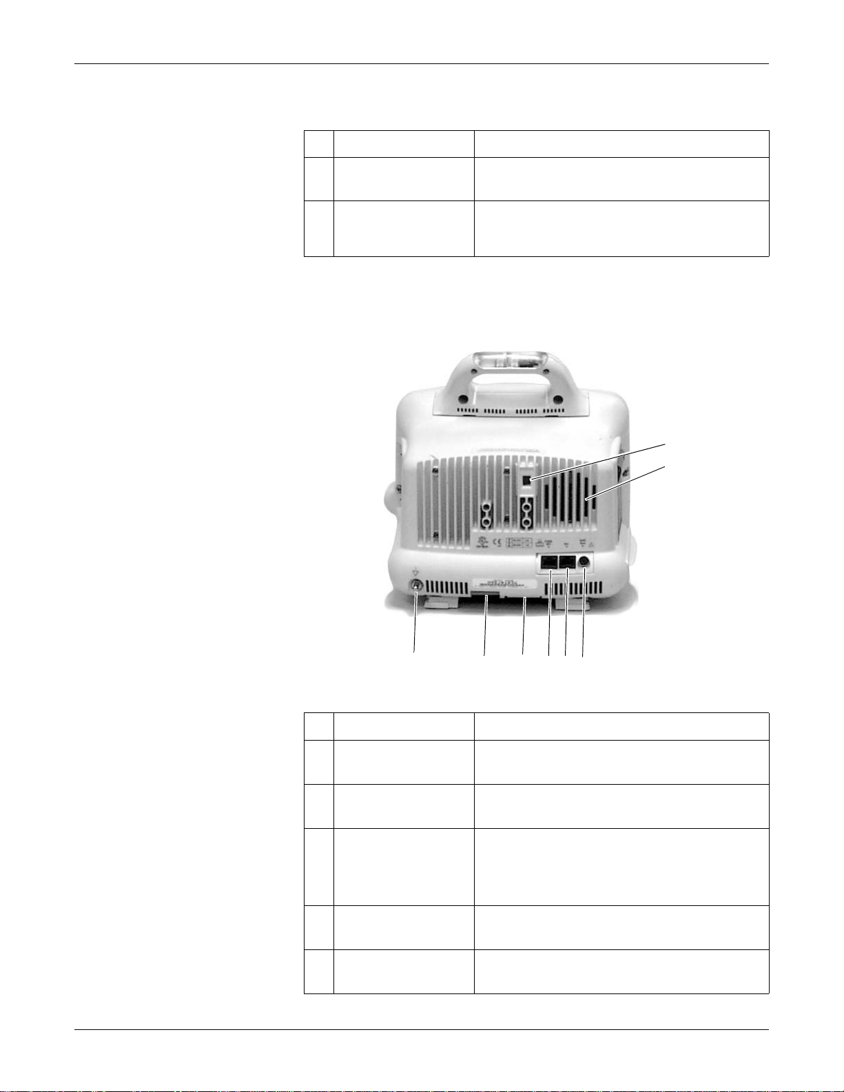
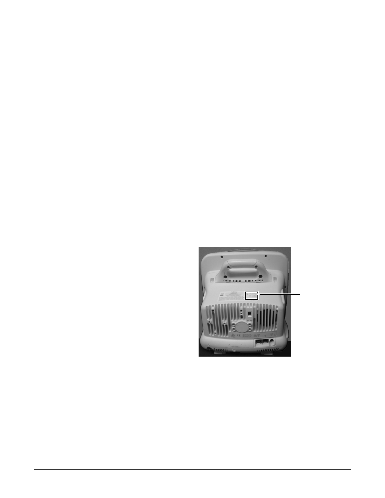
Back view
Built-in writer
A
(optional)
Battery compartment The battery packs are located in this compartment.
B
The built-in, 4 channel writer is located in the
center of the left side of the monitor.
The battery compartment may be a single plastic
door or two silicone doors.
All ports for equipment and network are on the back of the patient monitor.
Name Description
line voltage selector This selector is factory set to match the line voltage
A
audible alarm enunciator The internal speaker provides sound for audible alarms.
B
Defib Sync port Provides ECG analog output signals to user-supplied
C
rating for your country.
For better sound quality do not block speaker.
equipment. A 5-volt, 2-millisecond artificial pacer spike
is added to the analog output when PACE is on and
detection occurs.
Aux port Used for TRAM-rac 2A, BISx and other compatible
D
Ethernet port Used to connect a monitor to the Unity Network for
E
2-4 Dash 3000/4000/5000 2000966-456D
auxiliary devices.
patient monitoring or for software installation.
Page 23
Equipment overview: Components
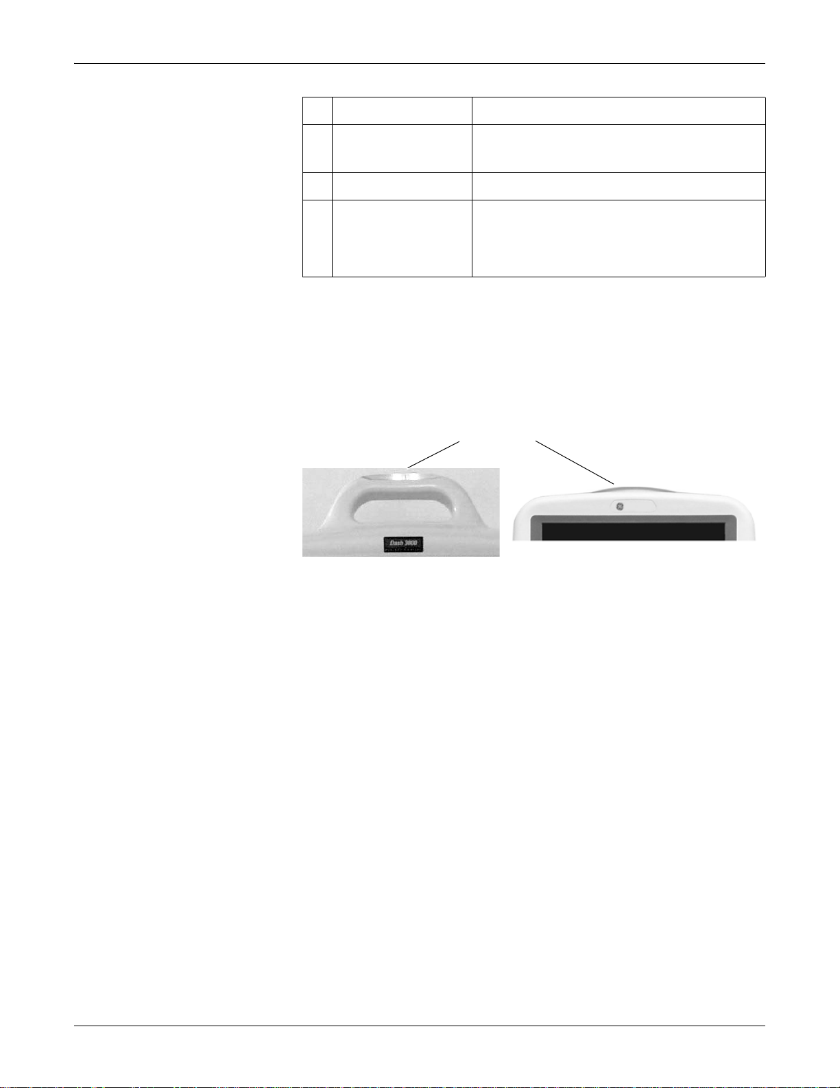
Alarm light indicator
Dash 3000 monitor Dash 4000 and Dash 5000 monitors
052B536A
Name Description
Optional alarm light indicator
An optional alarm light indicator may be built into the handle of the Dash 3000
patient monitor or into the display bezel of the Dash 4000/5000 patient monitor.
When activated, the LED indicator flashes red for Crisis patient status alarms and
yellow for Warning patient status and system alarms.
peripheral expansion
F
port
G AC power Used for connecting an AC power cable.
equipotential terminal For measurements in or near the heart we recommend
H
Used for connecting to a Dash™ Port
other compatible auxiliary devices.
connecting the monitor to the potential equalization
system. Use the green and yellow potential equalization
cable and connect it to this pin.
docking station or
Controls and indicators
The user interface consists of a flat panel display and the keypad assembly that
includes a Trim Knob control, function keys, and LED indicators.
Flat panel display
The active-matrix color liquid crystal display (LCD) is assembled into a shock
absorbing isolator that fits within the patient monitor’s front bezel to protect the
display from mechanical shock during use.
The acrylic optical filter protects the display panel from impact and enhances
visibility with its non-glare surface coating on the viewing side of the filter. It also
has a scratch-resistance surface coating.
Trim Knob control
The Trim Knob control is a 24-position rotary control with a push selection switch.
2000966-456D Dash 3000/4000/5000 2-5
Page 24

Function or power keys
Indicators
Equipment overview: Components
Dash 3000/4000 patient monitors
Power, Print, NBP Go/Stop, Zero All, Silence Alarm/Admit.
Dash 5000 patient monitor
Power, Standby, Admit/Discharge, NBP Go/Stop, NBP Auto, Print, Silence
Alarm, Zero All, Trend, Main Display.
Power key
The patient monitor is powered at all times when it is plugged into AC power. When
the patient monitor is not plugged in to AC power, press this key to turn on and turn
off the patient monitor.
When AC power is present, this key toggles the operational mode of the patient
monitor between normal operation and stand-by mode. In standby mode patient
monitoring discontinues. Only the charging function continues and the charging
status indicators operate as described below.
While the patient monitor powers up or changes between normal mode and standby
mode, all four front panel indicators illuminate.
AC power indicator
The indicator lights green when AC mains power is applied to the patient monitor
(including when the patient monitor is in the standby mode). The indicator does not
illuminate when the patient monitor has no AC mains power.
Battery power indicator
The indicator lights yellow when the patient monitor is operating on battery power.
The indicator does not illuminate when the patient monitor has no battery power.
2-6 Dash 3000/4000/5000 2000966-456D
Page 25
Equipment overview: Components
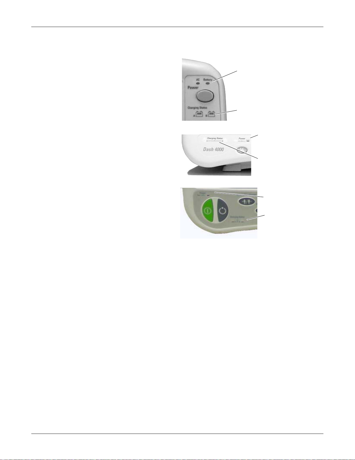
Charge status indicators
Battery power indicators
Battery power
indicators
Charge status
indicators
Dash 3000
Dash 4000
Charge status
indicators
Battery power
indicators
Dash 5000
009A
053A
868A
Battery indicators are located on the front panel of the patient monitor. They indicate
when battery power is used and the battery charging status.
Charging status indicators
An icon for each battery indicates its charging status. The battery icon lights yellow
when the respective battery is being charged. If both batteries are present and require
charging, then both icons illuminate even though they will be charged sequentially.
The battery icon lights green when the respective battery is fully charged.
When the patient monitor is operating under battery power the battery icons are not
illuminated. The icons are also not illuminated when the respective battery is either
not being charged, not installed, or has failed.
The following table explains what the charging status indicators mean.
NOTE
No specific indicator distinguishes a failed battery pack condition from a
condition where the battery is not installed or is not being charged. Go to the
Service Menu for Battery Status. Refer to “Battery alarms and messages” on
2000966-456D Dash 3000/4000/5000 2-7
Page 26

Equipment overview: Components
page 6-7 for further information.
LED color Explanation
Yellow Two battery icons, labeled Charging Status A and B, illuminate yellow
when the respective battery is being charged. If both batteries are present
and require charging, then both icons illuminate yellow even though they
charge sequentially.
Green The icon lights green when the respective battery is fully charged.
No light The icon does not illuminate under the following conditions:
The respective battery is not installed.
The patient monitor is operating on battery power.
A failure condition has been detected for the respective battery.
Battery status indicators
The battery status indicators are located inside the battery compartment. One green
LED indicator is located above each of the two battery slots and lights green when
the patient monitor is receiving power solely from the respective battery. The
indicators do not illuminate when the patient monitor is not battery powered.
Neither indicator lights when the patient monitor is operating from both batteries
simultaneously (e.g., in a very low battery charge condition when both batteries are
joined together in order to sustain operation of the patient monitor).
2-8 Dash 3000/4000/5000 2000966-456D
Page 27
Equipment overview: Components
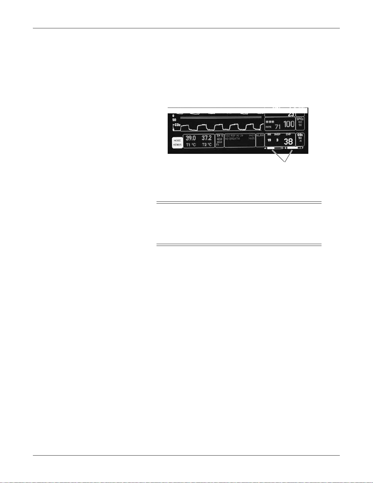
Battery capacity gauges
809A
Battery capacity gauge
On-screen capacity gauges indicate the battery's current state of health and charge
status. A battery capacity gauge for each battery present displays below the
parameter blocks in the lower right corner of the display. The capacity gauge
indicates the remaining charge capacity (usable energy left) for each battery.
The capacity gauges fill in from left to right proportional to the battery charge level.
The solid portion represents the full charge capacity of the battery as a percentage of
its design capacity.
Exchangeable or compatible battery packs
WARNING
EXPLOSION OR FIRE - Using non-recommended batteries
could result in injury/burns to patients and users. Only use
batteries recommended or manufactured by GE. The warranty can
be voided if non-recommended batteries are used.
Dash patient monitors running software versions 5.4 or later only recognize and
charge GE recommended batteries. Non-recommended batteries will run, but not
charge, the Dash patient monitor. If battery is labeled GE Approved, the battery is
compatible.
NOTE
Incompatible batteries display an “ERROR” message in the Battery Capacity
Gauge on the bottom right corner of the patient monitor screen.
Verify compatibility of an unmarked battery as follows.
1. Install a battery pack in the patient monitor.
2. Using the Trim Knob control, access the Service Mode menu starting from the
Main Menu. Select MORE MENUS > MONITOR SETUP > SERVICE
MODE.
3. Enter password using the Trim Knob control to select the day and month from
patient monitor screen with leading zeros. (e.g. July 4 = 0407).
4. Select BATTERY SERVICE.
5. Verify that the MANUFACTURER NAME does not display INCOMPAT,
NME, or UNKNOWN for the battery corresponding to BATTERY A or
BATTERY B slot.
2000966-456D Dash 3000/4000/5000 2-9
Page 28
Optional components
797B
823B
TRAM-rac 2A module housing
The TRAM-rac 2A module housing currently supports the SAM and ICG modules.
An integral power supply is used to run the TRAM-rac 2A and support the needed
voltages.
Equipment overview: Components
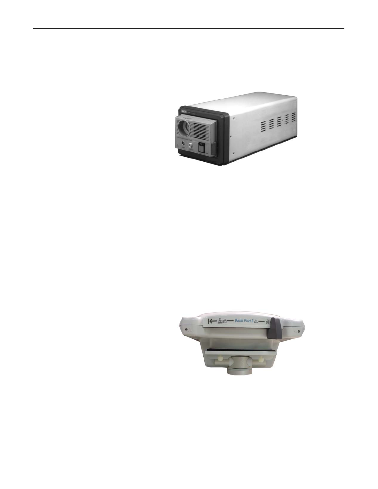
Dash Port 2 docking station
The docking station is a quick mount/dismount base for a Dash patient monitor. It
gives the patient monitor easy connect or disconnect access to AC power, Unity
Network
™
, a remote display, and auxiliary devices.
See the Dash Port 2 Docking Station Operating Instructions and the Dash Port 2
Docking Station Service Manual for additional information.
NOTE
When a Dash patient monitor is connected to the docking station, only the
docking station’s Ethernet port is active. The Dash patient monitor’s network
port remains inactive until the patient monitor is disconnected from the docking
station.
An optional remote display can be connected to the system for viewing on a larger
monitor, or in a separate room. The remote display requires:
Dash Port 2 docking station,
Dash 3000/4000 patient monitor software version 5 or later, or
Dash patient monitor software version 6 with Dash Port 2 software version 2.0,
and
Must be within 150 feet of the Dash patient monitor.
2-10 Dash 3000/4000/5000 2000966-456D
Page 29
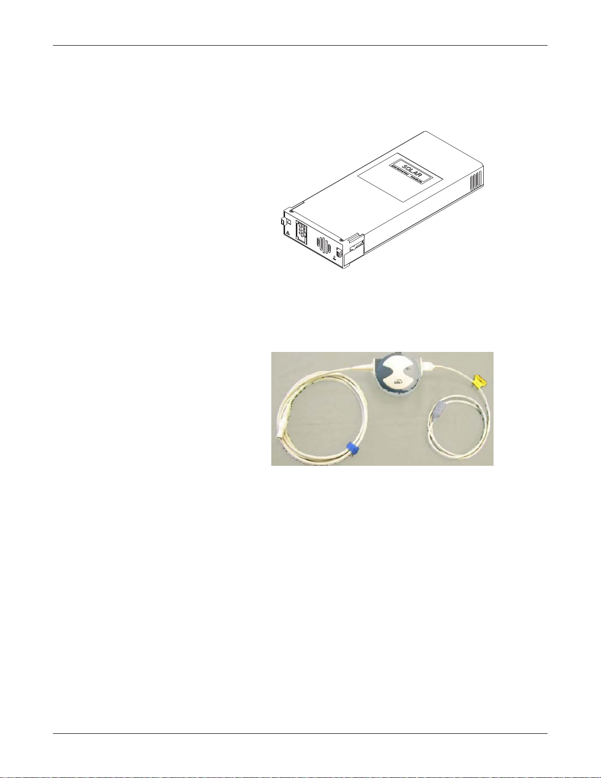
ICG module
825A
935A
BISx
Equipment overview: Components
The ICG module (impedance cardiography) measures and processes patient
hemodynamic data.
Available in software version 6 or later, BISx measures the effect of anesthetics and
sedatives on the brain.
2000966-456D Dash 3000/4000/5000 2-11
Page 30
Wireless connection
940A
Wireless
LAN label
Equipment overview: Components
The flexibility of the optional GE Unity Network is increased by using the wireless
network. The wireless connection allows the user to roam from one access point to
another, maintaining a strong seamless connection to the Unity Network. GE offers
802.11 and 802.11b wireless options.
The patient monitor, with its optional built-in wireless card, functionally performs
the same as a patient monitor connected directly to the optional Unity Network. It
can be viewed at the central station and by other GE monitors on the network (e.g.,
Dash 3000/4000/5000, Eagle
™
4000, and Solar™ patient monitors). Patient
monitors with a wireless connection can send and receive patient data via the access
points to the Unity Network.
NOTE
It is recommended that wireless patient monitors that are moved from room to
room have their patient monitor type conf igured as Rover or Rover/Combo
monitoring.
To extend the Unity Network to a hospital’s 802.11b wireless network, a proper
installation and configuration needs to be performed. To maintain continuous
wireless patient monitoring, refer to the wireless LAN Configuration Guide and
contact GE for consultation in integrating the Unity Network to a 802.11b wireless
network.
To identify a patient monitor with the wireless option, look for the wireless LAN
label.
2-12 Dash 3000/4000/5000 2000966-456D
Page 31

Optional remote control
821A
The optional remote control provides all patient monitor controls on a portable
component with a Trim Knob control, and allows the user to operate the patient
monitor from across the room. Eighteen hard keys are configured for adult, neonatal,
or operating room applications.
Equipment overview: Components
2000966-456D Dash 3000/4000/5000 2-13
Page 32

Equipment overview: Software packages and software options
Software packages and software options
Software packages
The Dash patient monitor comes configured with the Basic software package. This
package consists of standard-of-care parameters, lethal arrhythmia detection, dose
calculations, and features required by clinicians caring for acutely ill patients.
Two additional software packages can be purchased separately or in any
combination. These packages provide a variety of features that allow the patient
monitor to be configured to best meet the needs of its intended environment.
The Cardiac software package focuses on cardiac conductivity. Its features include
full arrhythmia analysis and storage, as well as ST segment trending, storage, and
templates. The ability to adjust the ST measurement point is also included in this
package.
The Cardiopulmonary software package centers on cardiac and pulmonary
hemodynamics. Features include the PA insert and wedge algorithms, the intraaortic balloon pump algorithm, and the thermodilution cardiac output algorithm,
including predefined computation constants for the catheters of major
manufacturers. Also included are cardiac and pulmonary calculations.
Software options
Three software options can be purchased separately or in any combination with the
software packages and software options.
The High Resolution CRG Trends option provides storage of up to 100 CRG events,
and up to 24 hours of CRG trend data, in addition to the CRG feature set found in
the Basic software package.
The 12SL™ ECG analysis program with Gender Specific Criteria and the Acute
Cardiac Ischemia–Time Insensitive Predictive Instrument (ACI-TIPI) analysis
option uses recorded ECG data to produce a numerical score which is the predicted
probability of acute cardiac ischemia. In addition, the gender-specific criteria
improves the detection of acute myocardial infarctions (AMI) in women.
The Unity Network option enables you to view other patients on the network,
interface with a central station and other network devices, and perform Combo or
Rover Combo monitoring.
2-14 Dash 3000/4000/5000 2000966-456D
Page 33

Equipment overview: Ethernet communication
Segment
Dash
Dash
CIC Pro
CIC Pro
Switches
1 to n
054B
Ethernet communication
About Ethernet
The GE Unity Network uses Ethernet for device to device communications. This
local area network links all patient monitors, clinical information centers, and other
GE equipment throughout the hospital. Depending on the construction of the
hospital, thick-net, thin-net, or CAT-5 twisted pair cabling is used. The Dash patient
monitor is designed to be used with twisted-pair cabling. Consult GE when trying to
interface with either thick-net or thin-net cabling. The real-time GE Unity Network
operates at 10 Mbps, half-duplex.
Twisted pair
Twisted pair is the most popular cabling because it is easy to install and flexible to
work with. It uses the star topology with a switch as the hub of the segment. A
maximum of 100 meters or 328 feet is the longest length of twisted pair cable
allowed. The maximum number of devices on the GE Unity Network is 1,000.
2000966-456D Dash 3000/4000/5000 2-15
Page 34

Equipment overview: Ethernet communication
Network Terms
Node
Each network device or node is assigned a Media Access Control (MAC) Address
number and requires a network connection to interface between the network device
and the network.
Media Access Control (MAC) address
A 48-bit address assigned by the manufacturer to uniquely identify a node of the
network. This is also known as the Ethernet address.
Switch
To implement the star topology, each network device is connected to a network
switch. The switch passes all network data between each network device in the star
segment. Typically, the switch supports 12 to 48 network devices and may be linked
to other switches to form larger networks.
Segment
IP address
Subnet
A network segment is comprised of all devices connected to one or many switches
which are in-turn connected together to form a larger network. The boundaries of the
segment are defined by networking equipment that regulate the flow of packets into
and out of the segment (e.g. routers and switches).
A 32-bit (IPv4) address assigned by the user (either statically or dynamically from a
server) to uniquely identify the packets from a device for routing purposes.
A subnet is a logical segment of a larger network that shares a common IP address
range as defined by a subnet mask. Proper subnetting can improve the performance
and security of a network.
2-16 Dash 3000/4000/5000 2000966-456D
Page 35

Equipment overview: Theory of operation
516A
Theory of operation
Components
The patient monitor is housed in a single package. The main components of the
assembly are:
Power supply
Data Acquisition System
Processor and power management subsystem (incl uding battery case and
expansion port)
Speaker
Handle subassembly (including the Alarm Light option)
Thermal printer (optional)
Battery
Overall patient monitor block diagram
2000966-456D Dash 3000/4000/5000 2-17
Page 36

Equipment overview: Theory of operation
Power supply
The subsystems within the patient monitor operate from a common 9 to 18 V power
bus. Due to the wide variety of voltages required by the various subsystems, power
is converted locally by each subsystem. This architecture results in an efficient and
compact system by reducing the number of conversions required and optimizing the
physical size of each converter for the specific application.
When operating on AC mains power, the power bus voltage is 18 V, generated by
the offline switching power supply.
No AC mains power switch is provided.
The line voltage range switch must be set to select 115 V or 230 V (90 to 132 VAC
or 190 to 264 VAC, respectively).
Data Acquisition System (DAS)
All interfaces to the patient occur through the DAS. The ECG function uses a direct
connection to the patient; therefore it is separately isolated from the other functions
(except respiration, which shares the ECG patient interface) to substantially reduce
coupling of noise and leakage currents to/from other functions. All remaining DAS
functions (e.g., pulse oximetry, NBP, invasive pressure, temperature, cardiac output,
and CO
) share a common isolation barrier.
2
NOTE
The patient monitor supports three SPO2 configurations, Generic Ohmeda
SPO2, Masimo SET SPO2, and Nellcor OxiMax SPO2.
2-18 Dash 3000/4000/5000 2000966-456D
Page 37

Equipment overview: Theory of operation
DEFIB PROTECTION MODULE -- 414639-002
DUAL TEMP/
CARDIAC
OUTPUT
INV BP1
INV BP2
SpO2
NBP
ETCO2
11 PIN
ECG
INPUT
CONNECTOR
22.1184
MHz
MOTOROLA
68332
RESET IC
DUAL INVASIVE BP -- 801466-001
NON-INVASIVE BP -- 2008654-001
TEMP CH1 -- 401788-004
TEMP CH2 -- 402100-004
PULSE-OXIMETRY -- 801368-001
NBP CUFF
PRESSURE SENSOR
CO2 SIGNAL PROCESSING & BARO PRESS -- 801368-001
CO2 IR SOURCE DRIVE / HEATER CONTROL -- 801370-001
TRANSDUCER
SIGNAL
CONDITIONING
H0H1H2H3H4H5H6
H7
HA0
HA1
HA2
HRD*
HWR*
HCS*
HOST_DMA_REQ*
+3.3V
+3.3V
+5V
+5V
+9-18V
+9-18V
GND
GND
GND
GND
GND
GND
GND
GND
SERIAL _DATA_IN
SERIAL_DATA_OUT
NBP_ENABLE
RESET*
7.3728
MHz
68HSC05
RESPIRATION
COUPLING CAP
MUX & A/D
VREF
DC-DC
CONVERTER
SECONDARY
CIRCUITRY
+12V
-12V
+5V
+12V
-12V
+5.5V
BAROMETRIC
PRESSURE
SENSOR
(MOUNTED ON
801368-001 HYBRID)
LDO
REG
+5V
(TO DIGITAL
CIRCUITRY)
ISOLATION BARRIER ISOLATION BARRIERISOLATION BARRIER
DC-DC
CONVERTER
SECONDARY
CIRCUITRY
DC-DC
CONVERTER
PRIMARY
CIRCUITRY
DC-DC
CONVERTER
PRIMARY
CIRCUITRY
+9-18V
+9-18V
38.4
KHz
PS FEEDBACK
COUPLER
7.5KV SPARK GAP
DIGITAL DATA
COUPLERS
PS FEEDBACK
COUPLER
DIGITAL DATA
COUPLERS
TRANSCUTANEOUS
PACE - BLANKING
CONTROL
7.5KV SPARK GAP
DAS_ID0
DAS_ID1
ISOLATION
BARRIER
Serial
E
2
PROM
4K x 8
CO2
CONTROL
LOGIC
FLASH
128K x 16
SRAM
128K x 8
MUX & A/D
VREF
RESPIRATION DEMODULATOR -- 400871-004
RESPIRATION CARRIER -- 400870-001
ECG PREAMP (I,II,III,V/V1) -- 400869-004
ECG PREAMP II (V2-V6) -- 401790-001
PACE DETECT (I,II,III,V/V1,V2-V6)-- 800982-001
FINAL AMP (I,II,III,V/V1) -- 401787-001
FINAL AMP (V2-V6) -- 401787-001
PACE REJECT (I,II,III,V/V1) -- 2007009-001
PACE REJECT (V2-V6) -- 401786-001
GENERAL
PURPOSE
8-BIT
HOST
INTERFACE
+9-18V
+9-18V
ACQ_TIMER_IRQ*
PWR_ENABLE*
TC_PACER_BLANK*
NBP
INTERFACE
TO PUMP,VALVES &
OVERPRESSURE
TRANSDUCER
+V_PUMP
PUMP_DRV
+12V_VALVE
GND
VALVE1_DRV
VALVE0_DRV
+5V
PRESSURE
NBP
INTERFACE
ASIC
528B
DAS block diagram with generic Ohmeda SPO2
2000966-456D Dash 3000/4000/5000 2-19
Page 38

Equipment overview: Theory of operation
The DAS block diagram with generic Ohmeda SPO2 consists of the following three
sections.
Section Description
ECG/Respiration Separately isolated section includes a 7.3728MHz 68HSC05
microcontroller, A/D conversion, signal processing hybrids and
DC-DC isolation converter.
Main DAS Separately isolated section includes a 22.1184MHz 68332
microcontroller with FLASH and SRAM memory, A/D conversion,
signal processing hybrids and DC isolation converter.
Non-Isolated
circuits
Includes serial and parallel host interfaces and NBP pump, valves,
and over-pressure circuitry.
ECG
The ECG function detects heartbeats and arrhythmias, measures heart rate (HR) and
ST segment deviation, and generates a 12SL diagnostic interpretation. Patient
alarms with adjustable high and low limits for HR and ST segment deviation are
provided. Additional patient alarms are provided for arrhythmias and PVCs. System
alarms for individual lead failure and all leads failure are provided.
The patient monitor accepts the green 3, 5, and 10-leadwire Multi-link ECG
connectors (compatible with Eagle 3000 monitor, Eagle 4000 monitor, and Tram
modules).
Respiration
The respiration function measures respiration rate (RR) and detects apnea through
the ECG leadwires using the impedance variation technique. Patient alarms for RR
(with adjustable high and low limits) and apnea (with adjustable time limit) are
provided. System alarms for lead failure, cardiac artifact, and learning are provided.
Generic Ohmeda pulse oximetry (SpO2)
The pulse oximetry function measures arterial oxygen saturation (SpO2) and
peripheral pulse rate (PPR). Patient alarms with adjustable high and low limits for
SpO
and PPR are provided. System alarms for probe off patient, low-quality signal,
2
and pulse search are provided.
The patient monitor accepts the blue color-coded pulse oximetry connector
(compatible with Eagle 3000 monitor, Eagle 4000 monitor, and the Tram x50-series
modules). The patient monitor with Generic Ohmeda SPO2 supports Nellcor probes.
2-20 Dash 3000/4000/5000 2000966-456D
Page 39

Equipment overview: Theory of operation
Non-Invasive blood pressure
The NBP function measures systolic pressure, diastolic pressure, mean pressure, and
heart rate. Patient alarms with adjustable high and low limits for systolic, diastolic,
and mean pressures are provided. System alarms for deflation failure, inflation
failure, maximum pressure exceeded, measurement time exceeded, pulse too weak,
hardware malfunction, and system pressure leak are provided.
The NBP function operates in manual, auto, and stat measurement modes. The
patient monitor has backup protections for magnitude and duration of applied cuff
pressure (with different settings in adult and neonatal modes).
The patient monitor accepts the rectangular NBP connector (compatible with the
Eagle 3000 monitor and some versions of the Tram module).
Invasive pressure
The invasive pressure function measures two blood pressures and calculates systolic
pressure, diastolic pressure, mean pressure, and pulsatile pressure rate where
applicable. Patient alarms with adjustable high and low limits for systolic pressure,
diastolic pressure, mean pressure, and pulse rate are provided for each channel.
System alarms for sensor status (failure and disconnected), Smart BP event
(artifact), zeroing status (not zeroed, failure, and pressure sensed), and PA Wedge
status (wait, inflate, processing, complete, and no pulse) are provided.
The user can set an adjustable low-pass filter to 12 or 40 Hz. The 12 Hz filter is
implemented in software; the filter is disabled at the 40 Hz setting.
The patient monitor accepts the red color-coded invasive pressure connectors
(compatible with the Eagle 3000 monitor, Eagle 4000 monitor, and Tram modules).
Temperature
The temperature function measures two temperatures. Patient alarms with adjustable
high and low limits for temperature are provided. System alarms for sensor and
calibration failures are provided.
The patient monitor accepts the brown color-coded connector (compatible with the
Eagle 3000 monitor, Eagle 4000 monitor, and Tram modules). The patient monitor
supports EN 12470-4 compliant probes. The probe type is determined by
identification signals in the probe adapter cable.
The temperature connector and measurement circuits are shared with the cardiac
output monitoring function; therefore you cannot use both functions concurrently. A
signal in the patient cable indicates the appropriate function.
2000966-456D Dash 3000/4000/5000 2-21
Page 40

Equipment overview: Theory of operation
Cardiac output
The cardiac output function measures blood temperature and injectate temperature,
and uses the thermal dilution method to calculate cardiac output. Patient alarms with
adjustable high and low limits for blood temperature are provided. System alarms
for sensor failure and unstable blood temperature are provided.
The patient monitor accepts the brown color-coded connector (compatible with the
Eagle 4000 monitor and Tram modules).
The cardiac output connector and measurement circuits are shared with the
temperature monitoring function. You cannot use both functions concurrently. A
signal in the patient cable indicates the appropriate function.
Carbon dioxide (CO2)
The CO2 function measures inspired and expired CO2 and respiration rate using the
infrared light absorption technique. The patient monitor connects to an external
CapnoFlex Low Flow Sidestream module or Novametrix Capnostat III sensor that
clips to an airway adapter in the patient’s ventilation circuit. The circuits to drive the
sensor and process its incoming signal are located within the DAS.
Patient alarms with adjustable high and low limits for inspired CO
and respiration rate are provided. An additional patient alarm for no breath detected
is provided. System alarms for various sensor conditions are provided.
The patient monitor accepts the yellow color-coded connector.
, expired CO2,
2
2-22 Dash 3000/4000/5000 2000966-456D
Page 41

Equipment overview: Theory of operation
931B
DAS block diagram with Masimo SET SPO2
2000966-456D Dash 3000/4000/5000 2-23
Page 42

Equipment overview: Theory of operation
The DAS system block diagram with Masimo SET SPO2 and four SuperStat BP
channels consists of the following three sections.
Section Description
ECG/Respiration Separately isolated section includes a 7.3728MHz Motorola
MC68HSC705C8A microcontroller, A/D conversion, signal
processing hybrids and DC-DC isolation converter.
Main DAS Separately isolated section includes a 22.1184MHz Motorola
MC68332 microcontroller with FLASH and SRAM memory, an
Analog Devices ADSP-21062 32-bit floating point digital signal
processor running at 12.096MHz, A/D conversion, signal
processing hybrids/modules and DC-DC isolation converter.
Non-Isolated
circuits
Includes ECG and Main DAS isolation power conversion circuitry,
serial and parallel host interfaces and NBP pump, valves, and
over-pressure circuitry.
Parameter functions of the DAS with Masimo SET SPO2,
four BP channels and Dinamap SuperSTAT NIBP
Except for the SPO2 parameter and additional 2 IBPs, the DAS with the Masimo
SET SPO2 parameter supports the same parameters as DAS with the GE Ohmeda
SPO2 parameter. Refer to “ECG” on page 2-20.
Probes and cable
The Masimo compatible DAS is intended for use exclusively with pulse-oximetry
probes from Masimo Corporation. An adapter cable is used to interface the probes to
the DAS front panel Nicolay connector. The Nicolay connector utilizes a key pattern
unique to Masimo.
2-24 Dash 3000/4000/5000 2000966-456D
Page 43

Equipment overview: Theory of operation
DEFIB PROTECTION MODULE 414639-
001
004
004
p
y
Y
ASSEMBLY
E
C
E
R
R
001
001
R
G
R
Y
DIGITAL
R
R
R
Y
R
R
+9-18V
FLASH
001
001
004
001
001
001
001
001
001
I
S
O
L
A
T
I
O
N
932A
DAS block diagram with Nellcor 05 (OxiMax) SPO2
4-IBP and SUPER BP -- 2013329-
REG
REG
TC_PACER_BLANK*
NBP_ENABLE
PWR_ENABLE*
SERIAL _DATA_IN
SERIAL_DATA_OUT
RESET*
DAS_ID0
+9-18V +9-18V
GND GND GND GND GND
GND
+5V +5V
+3.3V +3.3V
DAS_ID1
+9-18V +9-18V
GND
GND
COUPLER
PS FEEDBACK
(TO SPO2
MP100
+3.3V
(TO
+5V
CONNECTOR)
CIRCUITRY)
RESET IC
22.1184
38.4
KHz
NBP CUFF
(MOUNTED ON
801368-001 HYBRID)
PRESSURE SENSO
CO2 SIGNAL PRO CESSING & BA RO PRESS -- 801368-
PRESSURE
SENSOR
BAROMET RIC
7.5KV SPARK GAP
PCB
Module
MHz
68332
MOTOROL
Serial
2
VREF
CO2 IR SOURCE DRIVE / HEATER CONTROL -- 801370-
COUPLERS
DIGITAL DATA
UART
SRAM
128K x 8
PROM
4K x 8
E
CO2
ASIC
INTERFAC
512K x 8
MUX & A/D
H0 H1
H2 H3
ASSEMBL
NBP PUMP
NBP VAL VE/MANIFOL D
H4
H6
H5
H7
HA1
HA0
8-BIT
HOST
GENERAL
PURPOSE
INTERFACE
HA2
HRD*
HCS*
HWR*
I
SIGNAL
TRANSDUCE
OVERPRESSUR
DC-DC
TRANSDUCE
CONDITIONIN
PRIMARY
CIRCUITRY
CONVERTE
PS FEEDBACK
INTERFAC
NBP
COUPLER
7.5KV SPARK GAP
PACE - BLANKING
TRANSCUTANEOUS
CONTROL
COUPLERS
DIGITAL DATA
+9-18V
BARRIE
DC-DC
PRIMARY
CIRCUITRY
CONVERTE
DC-DC
CIRCUITRY
CONVERTE
SECONDAR
DC-DC
+12V
ISOLATION
CIRCUITRY
CONVERTE
SECONDAR
+5V
-12V
MHz
7.3728
68HSC05
VREF
MUX & A/D
RESPIRATION
COUPLING CAP
RESPIRATION CARRIER -- 400870-
RESPIRATION DEMODUL AT OR -- 400871-
ECG PREAMP (I,II,III,V/V1) -- 400869-
ECG PREAMP II (V2-V6) -- 401790-
PACE DETECT (I,II,III,V/V1,V2-V6)-- 800982-
FINAL AMP (I,II,III,V/V1) -- 401787-
PACE REJECT (I,II,III,V/V1) -- 401786-
FINAL AMP (V2-V6) -- 401787-
PACE REJECT (V2-V6) -- 401786-
BARRIE
ISOLATION
TEMP CH1 -- 401788-
+12V
TEMP CH2 -- 402100-
LDO
LDO
-12V
+5.5V
t
Em
ECG
11 PIN
INPUT
CONNECTOR
BARRIER
ISOLATION
DUAL TEMP/
INV BP1/ BP3 INV BP2/ BP4
SpO2
NBP
ETCO2
DASH Nellcor 05 Data
DETAILED BLOCK DIAGRAM
OUTPUT
CARDIAC
2000966-456D Dash 3000/4000/5000 2-25
Page 44

Equipment overview: Theory of operation
The DAS block diagram with Nellcor 05 DAS PCB assembly consisting of three
sections:
The DAS design includes the Nellcor MP100 Module technology. Nellcor SPO2 is
classified as motion-resistant. It uses advanced digital signal processing algorithms
to extract very low-level SPO2 signals in the presence of artifact induced noise.
Section Description
ECG/Respiration Separately isolated section includes a 7.3728MHz 68HSC05
microcontroller, A/D conversion, signal processing hybrids and
DC-DC isolation converter.
Main DAS Separately isolated section includes a 22.1184MHz Motorola
MC68332 microcontroller with FLASH and SRAM memory, an
Analog Devices ADSP-21062 32-bit floating point digital signal
processor running at 12.096MHz, A/D conversion, signal
processing hybrids/modules and DC-DC isolation converter.
Non-isolated circuits Includes serial and parallel host interfaces and NBP pump, valves,
and over-pressure circuitry.
The DAS contains all circuitry necessary to support the MP100 Module. The
Nellcor MP100 Module contains:
All SPO2 front end circuitry, such as the digitally programmable photodetector
signal conditioning, A/D conversion, digitally programmable back-to-back
LED IR/RED emitter drive and on-board diagnostic / sensor identification
signal processing circuits.
A digital signal processor (DSP), clock circuitry, and program memory. The
Nellcor SPO2 algorithms executes on the DSP. No external memory interface is
provided. The DSP is "reset-able" by the DAS CPU.
A UART for communication of commands and data.
Parameter functions of the DAS with Nellcor OxiMax SPO2,
four BP channels and Dinamap SuperSTAT NIBP
Except for the SPO2 parameter and additional 2 IBPs, the DAS with the Nellcor
OxiMax SPO2 parameter supports the same parameters as DAS with the GE
Ohmeda SPO2 parameter. Refer to “ECG” on page 2-20.
Probes and cable
The DAS is intended for use only with Nellcor digital probes. It is not for use with
non-Nellcor probes or with Nellcor R-cal (resistor id) probes. An adapter cable is
used to interface the probes to the DAS front panel Nicolay connector.
2-26 Dash 3000/4000/5000 2000966-456D
Page 45

Equipment overview: Theory of operation
Processor/power management subsystem
Overview
The main processor/power management PCB contains the electrical hardware to
provide data processing and display of patient and monitor configuration data,
communication and interface circuitry, and power conversion and battery
management functions for the patient monitor.
The high level of integration attained in the design of the processor/power
management PCB is attributed to the use of several highly integrated devices. A
complex communications controller, ASIC, and battery management hardware
significantly improve the performance and reduce the complexity and cost of the
assembly. In addition to the CPU, the main microcontroller contains a six-channel
communications processor as well as memory, PC Card, and video controllers. The
devices used in the core processing architecture all operate at 3.3 V to minimize
power consumption, yet the main processor and ASIC are tolerant of 5 V hardware
peripherals.
2000966-456D Dash 3000/4000/5000 2-27
Page 46

Equipment overview: Theory of operation
574A
Block diagram of microprocessor and power management subsystem
2-28 Dash 3000/4000/5000 2000966-456D
Page 47

Main microcontroller
Equipment overview: Theory of operation
The microcontroller contains two processors:
a true internal and external 32-bit CPU core, and
a communications processor module (CPM).
The CPM contains an 8 kilobyte dual port RAM to communicate with the CPU core,
and once configured communicates with external devices with minimum CPU
intervention. External logic is reduced by the internal memory controllers and a
system interface unit which provides a clock synthesizer and timers used in this
design. Writer communications is supported by direct memory access and
processing performance is enhanced by 4-kilobyte instruction and data caches.
Microcontroller feature Patient monitor function
Serial Communications Controller 1 Unity Network
Serial Communications Controller 2 DAS communication
Serial Management Controller 1 Peripheral expansion communication
Serial Management Controller 2 Reserved
Interprocessor-Integrated Controller Batteries, battery charger,
Real-time clock,
EEPROM,
digital potentiometer for display
brightness control
Serial Peripheral Interface DAC for ECG and BP analog outputs;
ASIC configuration
User Programmable Machine A Memory controller for synchronous
graphics RAM
User Programmable Machine B Memory controller for synchronous flash
General-Purpose Chip-Select Machine Memory and peripheral device control
LCD Controller Color display
PC Card Controller Future use
DMA Writer communication
System Phase-Locked Loop (SPLL) Generation of system clock from crystal
oscillator
2000966-456D Dash 3000/4000/5000 2-29
Page 48

Equipment overview: Theory of operation
Microprocessor supervisory circuit, microcontroller internal Watchdog timer
The microprocessor supervisory circuit provides reliable operation of the main
processor board. This circuit monitors the +3.3 V power supply and asserts a 140
mS active low reset pulse when the power supply voltage is below +3.0 V during
power-up and power-down conditions. A 3 V, 0.5 A hour lithium battery is used to
preserve the contents of two SRAM devices and a real-time clock (RTC) when VCC
is below the reset threshold.
System control logic
The system ASIC contains all of the system control logic for the processor/power
management PCB. Such functions include address decoding, peripheral read and
write control strobes, smart battery control logic, display control, multiple I/O ports,
and front panel key switch debouncing.
Memory
Eight megabytes of non-volatile memory are provided to support the boot code and
expansion memory such as high resolution graphic trends data storage. The boot
block is write protected.
Eight megabytes of non-volatile memory are provided to support the main software
application code.
Sixty-four megabytes of volatile memory are provided by the synchronous graphics
RAM. This memory is used for stack, variable storage, dynamically allocated
memory and video data storage.
One megabytes of battery-backed SRAM supports storage of 24 hours of 1-minute
resolution patient trends, an error log containing 50 input errors, and 50 output
errors and storage for the CPM buffers.
The patient monitor configuration data such as Internet and Ethernet addresses, unit
name and bed number are maintained in the 2 kilobytes EEPROM. The serial device
resides on the I
2
C bus.
2-30 Dash 3000/4000/5000 2000966-456D
Page 49

Real-time clock
Audio subsystem
Video subsystem
Equipment overview: Theory of operation
The real-time clock incorporates an on-board quartz crystal. This feature simplifies
the design and eliminates adjustments. The time of day on a standalone patient
monitor is maintained to an accuracy of 15 seconds in 24 hours to support 24 hour
trend data. The RTC device is one of the devices on the I
Audio tones are generated using a tone generator , a n audio amplifier, and an 8,
2.5-in. speaker. The tone generator has built in D/A converters and a mixer to
generate the dual frequency tones. Frequencies ranging from 150 Hz to 2800 Hz are
produced.
The microprocessor contains a video controller that supports real-time and non-realtime waveform drawing, menu drawing, and parameter display.
Display brightness is controlled by a 50 k digital potentiometer. The potentiometer
is interfaced to the brightness control input of an inverter.
2
C bus.
Analog outputs
Defib Sync
Two analog output channels support ECG and BP. The pace pulse is generated on
the main processor board and inserted into the analog out ECG signal. The digitalto-analog conversion for both ECG and blood pressure output signals are performed
on the main processing board via a two channel 12-bit serial DAC. Cal data is stored
on the processor/power management PCB.
The QRS complex of ECG data acquired from the DAS generates the marker-out
signal. A software selectable pulse width and pulse amplitude is provided in the
Boot Loader Menu.
2000966-456D Dash 3000/4000/5000 2-31
Page 50

Optional thermal printer
The thermal printer includes complete control of the print head to print the desired
waveforms and text as well as monitor power consumption. The host processor on
the main processing board has direct communication via an 8-bit data bus to the
processor residing within the thermal recorder.
The +9-18 V power supplied to the writer is heavily filtered to provide the storage
capability to smooth power surges and transients caused by abnormal thermal
printing. Such printing may occur if the patient monitor is subject ed to ESU noise.
In addition, a writer current limiting circuit restricts the current to the writer to 2.5
A. If this current limit is exceeded, the circuit faults and requires the current limiting
circuit to reset through a microprocessor port.
Optional alarm light indicator
An alarm light indicating two levels of visual alarms resides in the handle of the
Dash 3000 patient monitor and in the display bezel of the Dash 4000/5000 patient
monitors. Red and yellow alarm lights illuminate by addressing an ASIC output
port. The Dash 3000 alarm light interfaces to the processor/power management PCB
via the 40-pin writer interface. The Dash 4000/5000 alarm lights interface to the
processor/power management PCB via the 100-pin DAS/Display /Keyboard
interface.
Equipment overview: Theory of operation
PC card
The main processor contains a PC Card controller, which complies with the
PCMCIA standard. One 68-pin fully compliant Type II PC Card slot is supported in
this design for wireless card.
Peripheral expansion interface
A 20-pin peripheral expansion interface is provided to support future use. An active
low peripheral present signal may be polled by software to identify when a
peripheral is attached to the patient monitor. Asynchronous, AUX, and a switched
Ethernet serial communication channels are supported as well as switched +9-18 V
and +5 V power.
DAS communication
The microprocessor communicates with the DAS processor using the second serial
communication controller (SCC) of the communication processor module (CPM).
This asynchronous communication channel operates at TTL levels and is optically
isolated within the DAS.
2-32 Dash 3000/4000/5000 2000966-456D
Page 51

Equipment overview: Theory of operation
Optional Unity Network communication
The microprocessor provides an Ethernet controller, which is implemented on SCC1
in order to benefit from the additional buffer descriptors compared to SCC2.
Ethernet packets are stored in SRAM buffers and are transmitted and received by the
10BASE-T transceiver. The Ethernet clocks are generated from a 20 MHz crystal
oscillator circuit and the transceiver. The transceiver also provides a visual
indication in the form of four LEDS to identify packet transmit, receive, collision,
and link integrity. The status of received data is indicated by the link integrity signal,
which is used by the microprocessor to determine if the patient monitor is connected
to the Unity Network.
An isolation transformer provides basic insulation to the twisted pair interface
required to meet the ANSI/IEEE 802.3 standard (Ethernet). Isolation is required
because during transport the power cord with the ground conductor is not available
to provide a path for a fault condition. An 8-pin RJ-45 port containing two isolated,
differential pairs is provided to connect the patient monitor to a network hub.
NOTE
Power is not provided in the twisted pair interface as in the attachment user
interface (AUI) of other monitoring products.
Ethernet priority
Async communication
Ethernet communications are prioritized in the following order.
1. Top priority is the Peripheral Expansion interface.
2. Next priority is the Hardwired Ethernet connection at the back of the patient
monitor.
3. Lowest priority is the optional wireless connection.
If none of the above exist, then the patient monitor is a stand-alone monitor.
Asynchronous communication ports comply with the GEMMS AutoPort protocol
and are provided through an 8-pin RJ-45 port and the 20-pin peripheral interface
described in the next section.
2000966-456D Dash 3000/4000/5000 2-33
Page 52

Equipment overview: Theory of operation
Debug patient monitor and diagnostic LEDs
An integrated debugger operating in the debug mode within the main processor
provides basic emulator-like features such as modification of register and memory
locations and setting of breakpoints. The connector required for this serial
communication is a dual row 10-pin header. This connector is located within the
patient monitor and is not intended for field service use. Tracing of instructions and
logic analysis is provided by an adapter board that connects to a socket installed on
the main processor board instead of the microprocessor.
Three diagnostic LEDs located along the front edge of the board are provided for
general purpose use and are under software control. The LEDs interface directly to
port A of the microprocessor. A flashing green LED indicates normal monitoring
operation.
Main DC-DC converter section
The main DC-DC converter consists of two independent synchronous rectifier buck
regulators with one common controller.
The patient monitor uses a “point of use” power conversion architecture with +9-18
V being the main power distribution bus.
Battery subsystem
Four voltage outputs are developed on the processor/power management PCB:
+3.3 V,
+5 V,
+12 V, and
–12 V.
Each one of the four outputs are individually current limit protected against overload
and short circuit.
Battery charging and control is accomplished on the processor/power management
PCB.
The battery is a smart battery and features an on-pack fuel gauge.
2-34 Dash 3000/4000/5000 2000966-456D
Page 53

Equipment overview: Theory of operation
Lithium-Ion battery power
The patient monitor is designed to operate on battery power during transport or
whenever AC power is interrupted. A complete battery management system allows
you to obtain maximum battery performance. Audible and visual alarm s alert you
when loss of power is imminent and on-screen capacity gauges indicate battery
charge condition and capacity.
Depending on usage, you can get up to 2.5 hours of run time per battery for new,
fully-charged batteries. Monitoring NBP, CO2 and SpO2 drain battery power faster
than other parameters. The display technology and brightness, graphing, and
connection to a wireless network can also alter battery run times.
NOTE
A BATTERY LOW message at the top of the screen warns you prior to
complete loss of battery power. Replace the battery or connect the patient
monitor to an AC power source when the message displays.
The Lithium-Ion battery is a rechargeable battery containing Lithium-Ion cells. Each
battery contains an integrated electronic fuel gauge and a safety protection circuit.
Impact of Lithium-Ion Battery technology on the battery
The following are key points to know about Lithium-Ion battery technology:
The battery self-discharges on its own, even when it is not installed in a patient
monitor. This discharge is the result of the Lithium-Ion cells and the bias current
required for the integrated electronics.
The battery self-discharges. The self-discharge rate doubles for every 10 C
(18 F) rise in temperature.
The capacity loss of the battery degrades significantly at higher temperatures.
As the battery ages, the full-charge capacity of the battery degrades and will
permanently be lost. As a result, the amount of charge that is stored and
available for use is reduced.
How to improve battery performance
Installation guideline
Position the patient monitor in a location that does not artificially increase the
operating temperature of the battery.
To optimize battery life and performance, choose a location that does not
artificially increase the ambient temperature surrounding the patient monitor.
Do not place the patient monitor near a heat vent or near heat-generating
equipment, such as computer monitors.
Avoid placing the patient monitor in corners where the airflow may be
restricted.
2000966-456D Dash 3000/4000/5000 2-35
Page 54

Equipment overview: Theory of operation
857A
Design Capacity and Full Charge Capacity
Charging guideline
Use the Cadex SMart Two+ charger to charge the battery instead of charging the
battery inside the patient monitor.
The Cadex SMart Two+ charger maintains a lower battery cell temperature
during the charge cycle than the patient monitor. This reduction in temperature
will extend the life of the battery.
The Cadex SMart Two+ charger charges one battery in less than 4 hours and
two batteries in less than 8 hours. When two batteries are used, the charger
applies half of the charging current to each battery.
Conditioning guideline
Remove the battery from the patient monitor every six months and condition it using
the Cadex SMart Two+ charger. This condition cycle recalibrates the electronic fuel
gauge.
Storage guidelines
Do not purchase more batteries than you will use in one year. The battery does not
have an indefinite shelf-life. See “How to store the battery” on page 5-12.
How to identify battery charge capacity
Battery capacity definitions
The following terms are used to define the capacity of the battery:
Design Capacity — The theoretical capacity of the battery cells when the
battery is new.
Full Charge Capacity — The actual amount of charge the battery can store and
deliver to the patient monitor.
Remaining Charge Capacity — The amount of Full Charge Capacity currently
remaining in the battery. This is a percent of Full Charge Capacity.
Identify battery charge capacity using the patient monitor
One new, fully charged battery lasts about 2.5 hours. Two new, fully charged
batteries last about 5 hours.
A battery that has 100% Design Capacity and is charged to 100% of this capacity
lasts approximately 2.5 hours. However, as the Full Charge Capacity declines, the
approximate run time of a fully charged battery will decrease.
Single battery run time: approximately 2.5 hours – An icon fully outlined with
solid lines and completely filled indicates a new battery, fully charged to its Design
Capacity.
2-36 Dash 3000/4000/5000 2000966-456D
Page 55

Equipment overview: Theory of operation
858A
Full Charge Capacity
859A
Full Charge Capacity
50% Available Capacity
Single battery run time: approximately 2.0 hours – The dotted portion of the
icon outline shows that the battery has lost 20% of its Design Capacity. The solidoutline portion is filled in, showing that the battery is charged to 100% Full Charge
Capacity.
Single Battery Run Time: Approximately 1.0 Hours – The dotted portion of the
icon outline shows that the battery has lost 20% of its Design Capacity. The solidoutline portion is half filled in, showing that the battery is charged to only 50% of
available capacity.
Identify battery capacity using the Cadex SMart Two+
charger
When you select the Target Capacity switch on the charger, the charger compares
the battery’s performance to a 60%, 70%, or 80% target capacity set on the battery
charger. If the battery fails to meet the target performance, the battery charger will
prompt you to condition the battery. If after the condition cycle has been completed,
the battery does NOT meet the target performance, then the battery charger will
illuminate a “fail” light.
2000966-456D Dash 3000/4000/5000 2-37
Page 56

Equipment overview: Theory of operation
Identify battery status using the BATTERY STATUS menu
This menu option opens a menu and information window that provides current
battery status information.
1. Select MORE MENUS from the Main Menu.
2. Select BATTERY STATUS to display the BATTERY STATUS Menu and
information window.
If a battery is not present, NO BATT displays in the SLOT STATUS
column.
If communication with the battery has failed, NO COMM displays in the
SLOT STATUS row and UNKNOWN displays in all other rows.
If a battery is incompatible, INCOMPAT displays in the SLOT STATUS
column and UNKNOWN displays in all other fields.
2-38 Dash 3000/4000/5000 2000966-456D
Page 57

Battery Help menu
↓ ↑
835A
Equipment overview: Theory of operation
Each menu option opens an information window that includes the following
information:
RETURN — Returns to the Battery Status menu.
SLOT STATUS — Provides definitions of the battery conditions.
NO BATT — No battery is installed in this slot.
INIT... — Battery is just installed, establishing communication.
NO COMM — Communication with this battery has failed because it is
either sleeping, defective, or not a SMart Battery.
INCOMPAT — The battery is not compatible with this patient monitor’s
battery management system.
FAIL — See message displayed in the lower half of the display.
IN USE — This battery is currently powering the patient monitor.
FULL — Fully charged.
CHARGING — Currently being charged.
IDLE — Not currently in use or charging.
TIMES — Defines “time to empty” and “time to full.”
TIME TO EMPTY: — The time to empty represents an estimate of how
much longer the patient monitor will be able to run with the current
monitored parameters. Changi ng the setup, running NBPs, printing graphs,
etc. will likely change the value of the time remaining. This value is only
displayed when the patient monitor is powered by battery.
TIME TO FULL: — The time to full represents an estimate of the time
remaining before this battery is fully charged. Total recharge time for this
unit is the sum of both batteries’ time to full.
FUEL GAUGES — Explains the battery capacity gauges.
The fuel gauge is filled from the left to right proportional with the battery’s
charge level. The full rated capacity of a new battery of this type is represented
by a dashed outline. The maximum charge level for the battery currently
installed is represented by a solid outline. As a battery ages, its maximum
charge level becomes a smaller percentage of its Design Capacity. The solid
portion represents the current charge level of the battery as a percentage of its
maximum Full Charge Capacity.
2000966-456D Dash 3000/4000/5000 2-39
Page 58

Speaker
Handle subassembly
Equipment overview: Theory of operation
ALARMS — Explains low battery and battery fault alarms and messages.
FAULT STATUS MESSAGES: — General, charging, and temperature
failures indicate that the battery has failed, or the charging of the battery
has failed. Replace it with a different battery.
CONDITION: — Condition this battery using an external battery charger.
LOW BATTERY ALARMS: — The patient monitor will issue a System
Warning alarm when there is approximately 10 minutes per battery run
time remaining. The patient monitor will issue a System Warning alarm
when shutdown is imminent (less than one minute left of remaining run
time).
The speaker is used for audible notification of alarms.
The handle serves multiple purposes in the patient monitor. The modular design
enables the user to add adapters for specialized applications.
Interfaces
Ethernet
AUX
The Dash 3000 handle houses the optional alarm light. This light is visible for 360°
surrounding the patient monitor. The light is intended for applications when the
audible notification is not useful or effective, such as noisy environments (e.g.,
emergency vehicles) or quiet environments (e.g., neonatal care areas). The alarm
light indicates two levels of visual alarms:
Crisis alarms (red LED) and
Warning alarms (amber LED).
The handle also houses the wireless card antennas required for the optional wireless
card subsystem.
The Ethernet RJ-45 port provides a hardware connection to the optional Unity
Network. The patient monitor has a built-in transceiver for twisted-pair wire. Basic
insulation (1500 VAC) isolates the patient monitor from networked devices.
The AUX RJ-45 port provides an asynchronous communication connection to
devices within the bedside care area. Basic insulation (1500 VAC) isolates the
patient monitor from other devices.
Defib Sync
The Defib Sync port provides signals needed to perform synchronized cardioversion
with a defibrillator. The Marker Out signal is a pulse with selectable amplitude and
width that coincides with the patient’s ECG R-wave. The Marker In signal is
2-40 Dash 3000/4000/5000 2000966-456D
Page 59

Peripheral expansion
Wireless LAN
Equipment overview: Theory of operation
returned to the patient monitor by the defibrillator. The Marker In signal causes the
patient monitor to insert a defib marker in the displayed ECG waveform.
This port also provides two analog signals: ECG and invasive pressure. The patient
monitor provides the top displayed ECG signal with reconstructed pace pulses. You
can use this signal to trigger a defibrillator or intra-aortic balloon pump. BP1
produces the pressure signal and is intended for triggering an intra-aortic balloon
pump.
Asynchronous communication, Ethernet (shared with the Ethernet RJ-45 port), 9-18
V power, 5 V power, and discrete I/O signals are provided in the peripheral
expansion interface ports. The expansion port pairs with the AC mains power inlet
to supply power to the patient monitor through a peripheral device.
Initialization
Initialization begins on a card insertion function call from card services. The card
insertion function checks the manufacturer and card ID.
Initialization includes:
Access Configuration Register - Set through card services to the manufacturer's
recommended value.
The MAC Address is set to the Dash's MAC address to provide seamless
transition from hardwire to wireless and back.
SSID - Set to stored value. This ID must be the same between a card and an
access point for them to associate.
Reception
The read task waits on a receive interrupt from the card. When awakened, the packet
length is validated and the packet is copied into an ethernet buffer. A transfer
function using byte-sized transfers is used to ensure the access time to the card is
minimized. The packet length and pointer is returned to the ethernet stream.
2000966-456D Dash 3000/4000/5000 2-41
Page 60

Equipment overview: Theory of operation
Transmission
The write task waits on a transmission packet to be queued. When awakened, the
card is checked for association to an access point and for an available transmit
buffer. Transmits are discarded if both are not true. The packet is copied into the
card and a transmit command is issued to the card. The transmit task waits on a
transmit complete interrupt from the card. This ensures a transmit buffer will be
ready for the write.
Error handling
The card does not support partial packets or other receive errors. On a transmit error
the buffer will not be resent. Other events like buffer and queue overflows are
reported through the error log system.
Association status
Each association change is reported through the error log system.
Command queue
Commands are queued if the Wait On Command (WOC) bit indicates the card has
not completed the previous command. Commands that must complete are issued
through a function call that ensures the command is completed before returning.
This function delays between each check of the card to allow other tasks to run and
must not be called with interrupts off or from within an interrupt.
Storage and backup
Program code storage
Patient monitor settings
Card enable/disable
The patient monitor network task determines which active network media should be
used for ethernet communication. The peripheral connector has the highest priority
followed by the rear connector then wireless. Interrupts to the wireless card are
disabled until an enable wireless call is made by the patient monitor network task.
Disabling the card simply turns these interrupts back off. Card events like
association changes and receive overflows may be logged when interrupts are
enabled, but this provides faster switch over between hardwire and wireless than
resetting the card and re-initializing it on an enable.
Executable program code for the main processor, DAS processor, and thermal
printer are stored in non-volatile programmable memory. To display the revision of
the currently stored code, access the submenu of the main application’s Monitor
Setup menu.
The processor/power management PCB stores default patient monitor settings in
non-volatile memory. The user must restore the original settings if replacing the
board.
2-42 Dash 3000/4000/5000 2000966-456D
Page 61

Patient data storage
Time and date
Calibration data
Error log
Equipment overview: Theory of operation
Static RAM backed up by a lithium battery soldered onto the processor/power
management PCB stores patient data.
A patient monitor on the network maintains time and date for at least five years.
Time is accurate to within one second in ten hours. The clock is synchronized with a
time master on the optional Unity Network.
Calibration factors for NBP and CO2 are stored in non-volatile memory on the DAS
board.
Calibration factors for the analog output signals are stored in non-volatile memory
on the processor/power management PCB.
Input and output errors are retained in static RAM backed up by a lithium battery
soldered onto the processor/power management PCB. Contents are retained for at
least five years, provided that you exercise caution when you handle the board to
prevent inadvertently discharging the battery (e.g. when you ship the board for
problem diagnosis).
Optional thermal printer
The patient monitor uses the same 50-mm th ermal p rin ter mo dule that is used in th e
PRN 50 stand-alone printer. It prints up to four waveforms at chart speeds ranging
from 0.1 to 50 mm/s. The printer software is loaded independently from the patient
monitor’s software.
In the patient monitor, the printer module limits its current consumption to stay
within its allocated system power budget.
2000966-456D Dash 3000/4000/5000 2-43
Page 62

Equipment overview: Theory of operation
2-44 Dash 3000/4000/5000 2000966-456D
Page 63

3 Installation
2000966-456D Dash 3000/4000/5000 3-1
Page 64

Installation overview
599A
The following illustrates the installation steps for patient-ready monitoring.
1. Check received equipment against the sales order.
2. Unpack equipment and inventory contents.
3. Inspect the equipment and its components carefully prior to installation. Refer
to “Inspection” on page 3-3.
4. (Optional) Insert two batteries into the battery compartment slots. (Batteries
should be charged for 4 hours before using device on patients.)
5. Connect the power cord to the power supply inlet on the Dash patient monitor.
Secure the power cord to the back of the Dash using the power cord retention
clamp, unless the Dash is used with the Dash Port 2 docking station. Then plug
the power cord into the AC power outlet.
Installation: Installation overview
6. Connect peripheral equipment and network, if applicable.
7. Power up the Dash monitor. Go to “Configuration” on page 4-1 to configure for
stand-alone or networked monitoring.
8. Connect patient cables per the operator’s manual.
9. Qualified personnel must perform the “Dash installation checkout procedure”
on page 3-8, and should record the values of each required electrical safety test
in the “Checklist” on page C-1.
3-2 Dash 3000/4000/5000 2000966-456D
Page 65

Inspection
Installation: Inspection
Inspect the equipment and its components carefully prior to installation. Do not use
the equipment if damage is determined. Refer damaged equipment to qualified
service personnel.
1. Inspect the case for cracks or other physical damage to the case, the display
screen, and the keypad.
2. Inspect cables for fraying or other damage.
3. Inspect all plugs and connectors for bent pins or other damage.
4. Inspect the display face for marks, scratches, or other damage.
NOTE
Physical damage to the flat panel display glass may pose an implosion
hazard.
5. Safety labels and inscription on the device are legible.
NOTE
Damaged cables or equipment should be replaced by service personnel.
2000966-456D Dash 3000/4000/5000 3-3
Page 66

Before you begin...
634B
635A
Insert this end first
928A
Insert the battery packs in
the battery compartment.
The battery compartment
may be a single plastic
door or two silicone doors.
Battery status indicator
The following installation information assumes that the equipment is new from GE
manufacturing. The monitor was thoroughly tested before it was shipped. If
intending to use the Dash patient monitor under battery power, consider charging the
batteries in a charger during the checkout procedures. Otherwise, insert batteries in
the battery compartment as shown.
The battery compartment is located on the lower left side of the patient monitor.
Depending on your model, the battery doors may be one of the two variations shown
below. Battery indicators let you know when the patient monitor is using battery
power.
Installation: Before you begin...
CAUTION
Leaks from battery cells can occur under extreme conditions. The
liquid is caustic to eyes and skin. If the liquid comes into contact
with eyes or skin, flush with clean water and seek medical
attention.
WARNING
Make sure the batteries are completely inserted and that the
battery door is securely latched. Falling batteries could seriously
or fatally injure a neonatal patient.
3-4 Dash 3000/4000/5000 2000966-456D
Page 67

Connections
ETHERNET
Defib Sync connector
Aux Port
power connector
004A
peripheral expansion port
Back panel connections
The back of the patient monitor has all ports for equipment and network
connections.
Installation: Connections
ETHERNET
The ETHERNET port provides an ANSI/IEEE 802.3 10BaseT Ethernet standard
interface to the Unity Network.
TRAM-rac 2A housing connectors
The TRAM-rac 2A module housing connects to the patient monitor via a standard
category 5 patch cable (PN 418335-002) that plugs into the Aux port on the patient
monitor and to the Auto Port on the back of the TRAM-rac 2A module housing.
2000966-456D Dash 3000/4000/5000 3-5
Page 68

BISx module
AC power
Auto Port to the patient
monitor’s Aux Port
Async Comm
power switch
006A
822A
remote control
Aux port adapter
Installation: Connections
The TRAM-rac 2A module housing does not have an Analog Output connector.
The BISx module connects to the patient monitor via a RJ-45 cable that plugs into
the Aux port on the patient monitor and a Y-cable. One end of the Y-cable plugs into
a power supply and the other end plugs into the BISx module cable.
Remote control
The remote control connects to the patient monitor via a communications cable
which plugs into an Autoport to M-port adapter before it is inserted into the Aux
port on the Dash patient monitor or the Dash Port 2 docking station.
The remote control is programmed for specific care areas (adult, neonatal, or
operating room).
NOTE
The error message WARNING: REMOTE MISMATCHED WITH
MONITORING MODE displays if a mismatched remote control is connected
to the patient monitor.
3-6 Dash 3000/4000/5000 2000966-456D
Page 69

Defib sync
115V
line voltage selector:
115V for a 100-120V power source
230V for a 220-240V power source
004A
829A
AC power
Installation: Connections
The connector provides ECG analog output signals to user-supplied equipment.
CAUTION
Equipment damage. Connect all peripheral equipment before
plugging the power cord into an AC outlet. Otherwise, connectors
may be damaged.
Use this connector to apply power to the patient monitor. The patient monitor will be
powered at all times when using AC power (there is no AC power switch). The
patient monitor is preset at the factory for a specific line voltage. Before applying
power, verify the patient monitor’s line voltage setting matches your power supply.
If required, use a small bladed screw driver to change the line voltage setting. Refer
to the label on the back of the unit for the voltage and current requirements.
Power up
Configure
CAUTION
Verify the line voltage selector setting before plugging the power
cord into an AC outlet. The power supply may be damaged if the
power source applied is different from the line voltage setting.
After making all connections, plug the power cord into an AC wall outlet.
When all cables are properly connected, press the Power button to turn the patient
monitor on. All front panel indicators will illuminate until the power-up sequence is
complete. After approximately 20 seconds you should see a display on the screen.
Go to “Configuration” on page 4-1 to configure and set up the Dash patient monitor
for patient use.
2000966-456D Dash 3000/4000/5000 3-7
Page 70

Installation: Dash installation checkout procedure
Dash installation checkout procedure
GE recommends that qualified personnel shall perform the following tests, and
should record the results on the “Checklist” on page C-1
The Dash unit has been thoroughly tested before leaving manufacturing. There is no
need to re-test the parameters or operation of the unit upon installation except for the
following:
1. Electrical safety test. Refer to “Electrical safety tests” on page 8-4.
2. Refer to “Patient monitor power-up tests” on page 8-21.
3. Battery check. Ensure the battery indicator displays on the patient monitor
without an error.
4. If the Dash is networked:
Connect Dash to the MC network (wired or wireless) with any other GE
bedside monitor.
Select Vie w Other.
Select another bed.
Verify you can view another bed over the network.
5. If the Dash has TRAM-rac 2A housing connected via the Aux port:
Verify communication with a module in the TRAM-rac 2A housing by
confirming that the parameter for the ICG or SAM module displays on the
Dash.
6. If the Dash has a BISx module connected via the Aux port:
Verify communication with the BISx module by confirming that the
parameter for the module displays on the Dash.
3-8 Dash 3000/4000/5000 2000966-456D
Page 71

4 Configuration
2000966-456D Dash 3000/4000/5000 4-1
Page 72

Before you begin...
To configure a new patient monitor, you must first:
know that the new patient monitor’s software revision is compatible with the
write down the exact care unit name from the central station.
write down the bed name for the new patient monitor.
know if the patient monitor will be used for either stationary or ambulatory
know if the patient monitor will be connected to a wireless network.
know if the patient monitor will be moved from one intern et connection to
This section explains how to configure a patient monitor in both types of patient
monitoring system configurations:
Stand-alone patient monitor — the monitor is not interconnected to other
Networked patient monitor — the monitor is interconnected to other patient
Configuration: Before you begin...
other patient monitors connected to the Unity Network.
(telemetry) monitoring or both.
another.
patient monitoring system devices, and
monitoring system devices over the Unity Network for the sake of sharing
patient data. The patient monitor communicates with central stations, printers,
and other related equipment. This network is essentially an internet
implementation.
NOTE
The Unity Network is a purchased option.
4-2 Dash 3000/4000/5000 2000966-456D
Page 73

Service menus
Configuration: Service menus
There are two distinct service menus for the patient monitor. The Boot Loader
Service Menu is found in the Boot Code and is used for configuring the patient
monitor or when downloading the Boot Code and main processor code. The Service
Mode menu is located from the Main Menu and is used for various functions like
monitor settings, calibration, graph tests, and downloading patient monitor interface
software.
WARNING
The Boot Loader Service Menu and the Service Mode menus are
intended for qualified personnel only. Do not ‘experiment’ with
any commands found in the service menus. Experimenting with
service commands can lead to lost patient data, damaged
operating system software for the patient monitor, and even affect
the Unity Network.
2000966-456D Dash 3000/4000/5000 4-3
Page 74

Boot Loader Service Menu
Activate the Boot Loader program as follows:
1. Hold down NBP Go/Stop (or NBP Auto on Dash 5000) and ZERO ALL
(FUNCTION) on the front panel.
2. Press and release the Trim Knob control.
3. Keep holding NBP Go/Stop (or NBP Auto) and ZERO ALL (FUNCTION)
until the Boot Loader information appears on the display.
Following is a list of options in the boot code service menu.
Configuration: Service menus
Boot Loader Service Menu options
Menu Option Description
CHANGE INTERNET
ADDRESS
WARNING
Duplication of an Internet address on a network causes data
loss and possible Unity Network problems. If you change the
factory assigned Internet address, you must record all other
Internet addresses used on your network to avoid duplication.
SHOW INSTALL OPTIONS This option lists the options installed on the patient
CLEAR CONFIGURATION
MEMORY
SET CONFIGURATION This menu contains options for configuring the patient
VIDEO TEST SCREENS Various color screens for testing the display.
BATTERY SIMULATION This option is for engineering use only.
This option is used when changing the internet
protocol (IP) address.
monitor.
This option erases all patient histories and
programmed defaults in the monitor’s protected
memory. Clearing the configuration memory returns
the patient monitor defaults to the factory installed
defaults.
monitor. Refer to “Boot Code settings” on page 4-16.
WAKE UP BATTERY This option is used when the battery is dead. Refer to
“How to wake up the battery” on page 5-12.
OPTIONS MENU A unique password is required for each option.
Contact your sales/service representative to obtain a
password. You must provide your product serial
number and internet address. (The internet address
is displayed in the Boot Code banner information.)
4-4 Dash 3000/4000/5000 2000966-456D
Page 75

Main menu service mode
The Service Mode menu option items provide the service technician access to
general and technical built-in software functions of the patient monitor. Only
persons responsible for configuring and maintaining the patient mo nitor should
access the service mode menu option items.
The service technician can use the Service Mode menu to:
relay software information to design engineers,
calibrate and troubleshoot NBP functions of the patient monitor,
set admit menu options, operating mode of the patient monitor, and monitor
configure the patient monitor unit name, bed number and Internet address for
enter or change the time and date on the patient monitor.
Configuration: Service menus
default password,
use on the network, and
WARNING
The Boot Loader Service Menu and the Service Mode menus are
intended for qualified personnel only. Do not ‘experiment’ with
any commands found in the service menus. Experimenting with
service commands can lead to lost patient data, damaged
operating system software for the patient monitor, and even affect
the Unity Network.
Access the Service Mode
Access the Service Mode menu starting from the Main menu.
1. Select MORE MENUS > MONITOR SETUP > SERVICE MODE >
2. Enter password using the Trim Knob control to select the day and month from
patient monitor screen with leading zeros. (e.g. July 4 = 0407).
2000966-456D Dash 3000/4000/5000 4-5
Page 76

Service Mode options
Configuration: Service menus
Following is a list of options in the main code service menu.
Service Mode menu options
Menu option Description
REVIEW ERRORS For advanced troubleshooting by GE engineers. Error
log data can be transferred over the network to a central
station and then loaded onto a diskette for review. Refer
to “Error messages” on page 6-5 for details.
CALIBRATE For checkout or calibration of the noninvasive blood
pressure, ECG analog output, BP analog output, CO
service, and SAM service menu functions of the patient
monitor.
BATTERY SERVICE Provides battery data.
NOTE
If an INCOMPAT message displays in the Manufacturer Name column
and UNKNOWN displays in all other columns, the installed battery is
incompatible.
2
PATIENT-MONITOR TYPE For selecting the type of patient monitor desired, i.e
adult, neonatal or operating room. Refer to “Patient-
Monitor Type” on page 4-11 for detailed procedures.
WARNING
Changing the patient-monitor type will default the admit function
to Standard configuration. Different alarms and parameters are
activated for each selection.
NOTE
The keypad/remote control is DIDCA programmed for specific patient
monitor types. The error message, “WARNING: REMOTE
MISMATCHED WITH MONITORING MODE” displays if the patient
monitor and keypad/remote control do not match.
MENU SETUP Provides the following sub-menus: (Refer to “Service
Mode settings” on page 4-11 for detailed procedures.)
ADMIT MENU: STANDARD
Allows you to determine the function of the patient
monitor. The four variables include stationary or
ambulatory (telemetry) patient monitoring with a
monitor that always stays in one room (STANDARD)
or a monitor that moves from room to room (ROVER).
MONITOR DEFAULTS PASSWD
Allows you to set the patient monitor so that a
password is Required or Not Required for entry into
the Monitor Defaults menu section. If selected, the
password will be the same as the Service Mode menu
password.
4-6 Dash 3000/4000/5000 2000966-456D
Page 77

Configuration: Service menus
Service Mode menu options (Continued)
Menu option Description
MONITOR SETTINGS Provides the following sub-menus: (Refer to “Service
Mode settings” on page 4-11 for detailed procedures.)
SET UNIT NAME
Allows changes to the care unit name. After initial
setup, this name should not be changed or
communication to the central station will be corrupted.
Note that the care unit name must be registered
exactly the same in the central station and the patient
monitor.
SET BED NUMBER
Allows changes to the bed number. After initial setup,
this number should not be changed or communication
to the central station will be corrupted. Note that the
bed number must be registered exactly the same in
the central station and the patient monitor.
SET INTERNET ADDRESS
Allows changes to the internet (IP) address. An
incorrect internet address may also prevent the
patient monitor from viewing other monitors on the
network even though the unit names match. Whether
or not this can occur depends on the network topology
at the installed site.
WARNING
Duplication of an internet (IP) address on a network causes lost
data. If you change the factory assigned internet address, you
must first record all other internet addresses used on your
network to avoid duplication.
NOTE
An incorrect internet address may also prevent the patient monitor from
viewing other monitors on the network even though the unit names match.
Whether or not this can occur depends on the network topology at the
installed site.
2000966-456D Dash 3000/4000/5000 4-7
Page 78

Configuration: Service menus
Service Mode menu options (Continued)
Menu option Description
MONITOR SETTINGS (cont.) CONFIGURE WIRELESS LAN
Enable and configure the wireless LAN option. (Refer
to “Confirm or configure wireless LAN” on page 4-14
for detailed procedures.)
WIRELESS LAN STATUS
Displays wireless LAN status.
STORE DEFAULTS FOR NETWORK TRANSFER
Saves the patient monitor defaults for transfer to
another patient monitor with the same software
version, software package, patient monitor type, and
country code. It stores all patient monitor defaults,
(including WLAN configuration) custom default
names, and 12 SL location and site.
SET LOCATION ID
Enter the location identification for the MUSE system.
SET SITE NUMBER
Enter a site number if your institution has multiple
buildings. A MUSE system can be used as a site
number.
COPY UNIT DEFAULTS Use to copy patient monitor defaults from one patient
monitor to another patient monitor. Refer to
“Configuration” on page 4-1 for detailed procedures.
PRINT TEST PATTERN Allows you to run a graph test pattern. The choices are
Start and Stop.
TIME AND DATE Allows changes to the time and date and may affect the
time and date for the entire monitoring network. (Refer to
“Set time and date” on page 4-21 for detailed
procedures.)
WARNING
Loss of patient history. This menu should rarely be used because
patient histories will be lost.
4-8 Dash 3000/4000/5000 2000966-456D
Page 79

Procedures
Configuration: Procedures
Listed below are the patient monitor settings that can be configured. Each procedure
is described on the next pages.
From the Main Menu
“Set print locations” on page 4-10
From Service Mode
“Set Unit Name” on page 4-11
“Set Bed Number” on page 4-11
“Patient-Monitor Type” on page 4-11
“Admit Menu” on page 4-13
“Confirm or configure wireless LAN” on page 4-14
From Boot Code
“Set Defib Sync Voltage and pulse width” on page 4-16
“Set Line Frequency” on page 4-16
“Set CIC and QS protocol” on page 4-17
“Set MUSE system protocol” on page 4-17
“Transcutaneous Pace Blank Length” on page 4-17
“Set Country Selection” on page 4-18
“Set Language” on page 4-18
“Enable or disable AFIB Identification” on page 4-19
“Enable or disable IntelliRate” on page 4-19
“Analog Out Buzz” on page 4-20
Also see “Advanced user procedures” on page 4-21 to
“Set time and date” on page 4-21
“Transfer monitor defaults” on page 4-22
After completing all necessary procedures, go to “Functional and electrical safety
checks” on page 8-1.
2000966-456D Dash 3000/4000/5000 4-9
Page 80

Set print locations
Configuration: Set print locations
NOTE
Dash patient monitors and printers must be networked prior to setting locations.
Access the Manual Print Location option as follows.
1. Select MORE MENUS > MONITOR SETUP > PRINT SETUP > PRINT
LOCATION > MANUAL PRINT LOCATION.
2. Using the Trim Knob control, choose the manual print location from the list.
3. Select PRINT ON ALARM LOCATION.
4. Using the Trim Knob control, choose the alarm print location from the list.
5. Select PRINT WINDOW LOCATION.
6. Using the Trim Knob control, choose the print window location from the list.
7. Select 12 LEAD PRINT LOCATION.
8. Using the Trim Knob control, choose the 12 lead print location from the list.
4-10 Dash 3000/4000/5000 2000966-456D
Page 81

Configuration: Service Mode settings
↓ ↑
040A
↓ ↑
041A
Service Mode settings
From the Main Menu,
1. Select MORE MENUS > MONITOR SETUP > SERVICE MODE.
2. Enter password using the control to select the day and month from patient
monitor screen with leading zeros. (e.g. July 4 = 0407)
Set Unit Name
Up to seven characters are used to identify the care unit. These characters display at
the top right of the screen immediately preceding the bed number.
1. Enter Service Mode (See “Service Mode settings” on page 4-11) and select
MONITOR SETTINGS > UNIT NAME.
Set Bed Number
Patient-Monitor Type
2. Use the Trim Knob control to select and change each character. Up to seven
characters may be entered.
3. Select SET UNIT NAME and press the Trim Knob control to exit.
The bed number identifies a particular patient bed. Up to five characters are used to
identify bed number. This number displays at the top right of the screen.
1. Enter service mode (See “Service Mode settings” on page 4-11) and select
MONITOR SETTINGS > UNIT NAME > SET BED NUMBER.
2. Use the Trim Knob control to select and change each character. Up to five
characters may be entered.
3. Select SET BED NUMBER and press the Trim Knob control to exit.
The Patient-Monitor Type selection determines the type of patient monitor desired,
e.g., adult, neonatal or operating room. Different alarms and parameters are
activated for each selection.
2000966-456D Dash 3000/4000/5000 4-11
Page 82

Configuration: Service Mode settings
↓ ↑
042A
CAUTION
Each time the patient-monitor type is changed, the ADMIT
MENU function defaults to STANDARD configuration. Be aware
that some patient alarms and parameters may be changed.
NOTE
The keypad/remote control is DIDCA programmed for specific patient monitor
types. The error message, “WARNING: REMOTE MISMATCHED WITH
MONITORING MODE” displays if the patient monitor and keypad/remote
control do not match.
1. Enter service mode (See “Service Mode settings” on page 4-11) and select
PATIENT-MONITOR TYPE. Be sure to read the information in the Attention
box before changing anything.
2. Rotate Trim Knob control to select the type of environment the patient monitor
will be used in.
3. Press Trim Knob control to exit. Your selection displays at the top left of the
screen after the date.
4-12 Dash 3000/4000/5000 2000966-456D
Page 83

Admit Menu
↓ ↑
513A
Configuration: Service Mode settings
The Admit Menu selection determines the function of the patient monitor. Before
configuring the Admit Menu, you must know if the patient monitor will be used for
standard adult, neonatal, or operating room monitoring, and if the patient monitor
will be moved from room to room. All combinations are explained below.
STANDARD—configures the patient monitor to stay in one room for stationary
monitoring only. Patient monitors not connected to the Unity Network (Ethernet
connection) must use STANDARD configuration only.
ROVER—configures the patient monitor to move from room to room for
stationary monitoring only.
COMBO—configures the patient monitor to stay in one room for both
stationary and ambulatory (telemetry) monitoring. This patient monitor displays
all Tram module data combined with ECG data for ambulatory patients.
NOTE
Users should be aware of a possible time discrepancy between the
waveforms from the Telemetry device and the waveforms hard-wired to the
Dash patient monitor. Users should not consider these waveforms to be
synchronous. If absolute synchronicity is desired, Combo mode should be
discontinued and the ECG waveforms should be acquired via the hardwired bedside patient monitor.
ROVER COMBO—configures the patient monitor to move from room to room
for both stationary and ambulatory (telemetry) monitoring.
1. Enter service mode (See “Service Mode settings” on page 4-11) and select
MENU SETUP > ADMIT MENU.
2. Use the Trim Knob control to select the function of the patient monitor.
3. Press Trim Knob control to exit.
2000966-456D Dash 3000/4000/5000 4-13
Page 84

Configuration: Service Mode settings
933C
hex key index #1
hex key index #2
hex key index #3
hex key index #4
PMK calculation,
if TKIP
Confirm or configure wireless LAN
Confirm or configure the optional wireless LAN as follows.
1. Enter Service Mode (See “Service Mode settings” on page 4-11) and select
MONITOR SETTINGS > CONFIGURE WIRELESS LAN.
2. Select WIRELESS and set to ENABLED.
3. Select and enter SSID. If you change the SSID for TKIP, you must enter the
PASS KEY (even if it didn’t change) to recalculate the PMK.
4. For 802.11b, select and enter SECURITY.
5. If WEP, enter PASS KEY or hex key and KEY INDEX to match the
configuration on the access point. (See the definitions table on the following
page.)
If TKIP, enter PASS KEY. PMK is calculated and displayed below the hex
keys. Hex keys display although not used by TKIP.
NOTE
Entering a WEP hex key clears out the pass key.
The Hospital IT or a group that is responsible for the hospital's wireless
network can obtain the SSID and security settings (type, pass key and key
index) for the 802.11b wireless Dash.
Type in the PASS KEY exactly, using no extra spaces. PASS KEY entries
must be at least 8 characters for TKIP. The message TKIP KEY MUST BE
AT LEAST 8 CHARACTERS displays.
The SSID and PASS KEY entries are limited to 20 characters of upper/
lower case letters and numbers.
The SSID and PASS KEY entries are case sensitive.
Do not use special characters or quotes.
6. Select PRIORITY. Set to NORMAL unless otherwise specified by the network
4-14 Dash 3000/4000/5000 2000966-456D
specialist.
Page 85

Configuration: Service Mode settings
7. Manually reboot the Dash patient monitor.
Term Definition
SSID SSID is an acronym for Service Set Identifier.The SSID is a sequence of
numbers and characters that represents the ID, a name, of the wireless
network. For the 802.11b wireless Dash to connect wirelessly, the SSID
from the wireless network must match the SSID of the 802.11b wireless
Dash. A 802.11b wireless Dash has a default SSID of rtGEHClinical.
SECURITY A 802.11b wireless Dash provides three levels of security: NONE, WEP
128 bit, WPA-PSK (TKIP).·
NONE provides no security to the wireless communication
WEP 128 bit, Wired Equivalency Privacy, provides some level of
security, but it is less secure than WPA-PSK (TKIP).
WPA-PSK (TKIP), Temporal Key Integrity Protocol, is more secure than
WEP. TKIP has a method to change it's security key for each data
connection every second. For the 802.11b wireless Dash, WPA-PSK
(TKIP) is recommended.
PASS KEY Pass Key is equivalent to passphrase. This is a sequence of words for the
wireless Dash to connect to a security enabled wireless network, WEP
128 bit or WPA-PSK (TKIP). When WEP 128 bit security is selected, the
wireless Dash generates the 26 hex characters for four different keys,
displayed in four different rows (1st row represents a key index of one, 2nd
row for a key index of two, 3rd row for a key index of three and 4th row for
a key index of four). One of these keys needs to match the WEP 128
security setting in the access point for the wireless Dash to communicate
properly. When WPA-PSK (TKIP) is selected, the wireless Dash will not
generate the 26 hex characters. Pass Key or passphrase needs to match
the WPA-PSK (TKIP) setting in the access point in order for it to
communicate properly.
KEY INDEX (only required for WEP 128 bit)
When WEP 128 bit security is selected, the wireless Dash and the
wireless network need to share a same key index.
2000966-456D Dash 3000/4000/5000 4-15
Page 86

Configuration: Boot Code settings
Boot Code settings
To activate the Boot Code,
1. With power on, hold down NBP Go/Stop (or NBP Auto on Dash 5000) and
ZERO ALL.
2. Press and release the Trim Knob control.
3. Keep holding NBP Go/Stop (or NBP Auto) and ZERO ALL until the Boot
Code information appears on the display.
Set Defib Sync Voltage and pulse width
The patient monitor controls the analog out signal used to trigger a defibrillator.
Refer to the defibrillator manufacturer’s manual for the required pulse amplitude
and duration.
Configure or change the Marker Out signal of the DEFIB SYNC connector as
follows.
Set Line Frequency
1. Activate Boot Code (“Boot Code settings” on page 4-16) and select SET
CONFIGURATION menu option.
2. In the CONFIGURATION MENU, select:
1 Defib Sync Voltage: and choose 5V or 12V amplitude.
2 Defib Sync Pulse Width: and choose 10 ms or 100 ms for pulse duration.
3. Select Exit and wait for the patient monitor to display the message, “Writing
settings to EEPROM...”
4. Manually reboot the patient monitor to implement this change.
Configure or change the patient monitor line frequency to 50 or 60 Hz as follows.
The default is 60 Hz.
1. Activate Boot Code (“Boot Code settings” on page 4-16) and select SET
CONFIGURATION menu option.
2. Select Line Frequency then choose 50 Hz or 60 Hz line frequency.
3. Select Exit and wait for the patient monitor to display the message, “Writing
settings to EEPROM...”
4. Manually reboot the patient monitor to implement this change.
4-16 Dash 3000/4000/5000 2000966-456D
Page 87

Set CIC and QS protocol
The CIC and QS Protocol default setting is Seg50/51 (Segment 50/51) and should
not be changed. However, future products may require Hilltop protocol. Use the
Boot Code Service Menu to change the CIC Protocol and QS Protocol.
Set MUSE system protocol
The patient monitor transmits 12SL and ACI-TIPI data over the optional Unity
Network to the MUSE System and ST Guard. The formats used for this process are
Hilltop and Segment 50/51. Since the Segment 50/51 format does not support 500
Hz ECG data or ACI-TIPI, records originally stored on the MUSE System in Hilltop
format cannot display at the ST Guard. The default setting is Hilltop.
1. Activate Boot Code (“Boot Code settings” on page 4-16) and select SET
2. Select MUSE System Protocol then choose Hilltop or Seg50/51.
Configuration: Boot Code settings
CONFIGURATION menu option.
Hilltop—Sends 12SL records to the MUSE System in Hilltop format. The
12SL records contain 500 samples per second of ECG data. ST Guard will
not be able to retrieve 12SL records stored on the MUSE System in Hilltop
format.
Seg50/51—Sends 12SL records to the MUSE System in Segment 50/51
format with MAC Rhythm statements. The 12SL records stored on the
MUSE System contain 240 samples per second of ECG data. ST Guard can
retrieve 12SL records from the MUSE System. ACI-TIPI data can not be
retrieved at the MUSE System if this protocol is selected.
3. Select Exit and wait for the patient monitor to display the message, “Writing
settings to EEPROM...”
4. Manually reboot the patient monitor to implement this change.
NOTE
Before you can transmit data to the MUSE System and ST Guard, you must
set up the MUSE system’s Location ID and Site Number.
Do not configure MUSE system’s location at Site 0. Site 0 appears invalid
to MUSE and any message coming from a device on Site 0 is dumped.
5. Refer to “Service Mode settings” on page 4-11 and select MONITOR
SETTINGS > SET LOCATION, then select SET SITE NUMBER.
Transcutaneous Pace Blank Length
This menu option is reserved for future use and should not be changed.
2000966-456D Dash 3000/4000/5000 4-17
Page 88

Set Country Selection
Set Language
Configuration: Boot Code settings
Select DEFAULT or FRANCE to choose a particular set of GE factory defaults.
1. Activate Boot Code (“Boot Code settings” on page 4-16) and select SET
CONFIGURATION menu option.
2. Select Country Selection and choose language.
3. Select Exit and wait for the patient monitor to display the message, “Writing
settings to EEPROM...”
4. Manually reboot the patient monitor to implement this change.
Select Set Language to change the language of the displayed text.
1. Activate Boot Code (“Boot Code settings” on page 4-16) and select SET
CONFIGURATION menu option.
2. Select the SET LANGUAGE menu option.
3. Select the appropriate language.
4. Manually reboot the patient monitor to display the new language.
French language information
When the patient monitor Locale (language) is set to French_France, alarm pause
duration is three minutes. Refer to the Alarms chapter in the operator’s manual.
Czech, Hungarian, Polish, or Russian language information
Special characters within alarm broadcasts, messages, patient name, site name, or
location fields that are sent over the optional Unity Network cannot be displayed by
equipment that does not support these languages. Special characters may appear as
either blanks, asterisks, a series of square boxes, or no character is displayed at all
because the ability to display Cyrillic (Russian alphabet) and special Czech,
Hungarian, or Polish characters does not exist on this equipment.
Chinese and Japanese language information
When the patient monitor Locale (language) is set to Chinese or Japanese, the
following conditions apply:
Text for alarm broadcast over the optional network is in English.
All text input is in English only (e.g., text for unit name, bed name, patient
information, and custom default name).
Chinese Language
NOTE
The following two items are only available when the Chinese language is
selected. The factory default is disabled.
4-18 Dash 3000/4000/5000 2000966-456D
Page 89

Configuration: Boot Code settings
Select 3.2s baseline filter coefficent to enable or disable the 3.2 second baseline
filter time constant.
Select Minimum Waveform Width Reduction to enable or disable the size
reduction of the LCD waveform line width.
Enable or disable AFIB Identification
NOTE
This feature is already enabled if the Cardiac software option is purchased.
Select AFIB Identification to enable or disable the atrial fibrillation detection
feature.
To verify the option has been enabled on the patient monitor,
1. Select the following menu options: MORE MENUS > MONITOR SETUP >
SOFTWARE CONFIGURATION.
2. Verify that ATRIAL FIB is listed under “ENABLED SOFTWARE
OPTIONS.”
To change the status of this feature,
1. Activate Boot Code (“Boot Code settings” on page 4-16) and select SET
CONFIGURATION menu option.
2. Select the AFIB Identification menu option.
3. Select enabled to activate this option, or disabled to deactivate this option.
4. Select Exit and wait for the patient monitor to display the message, “Writing
settings to EEPROM...”
5. Manually reboot the patient monitor to implement this change.
6. Refer to the operator’s manual to configure the patient monitor to use this
feature.
Enable or disable IntelliRate
IntelliRate heart rate calculation feature is enabled from the factory.
To verify the option has been enabled on the patient monitor,
1. Select the following menu options: MORE MENUS > MONITOR SETUP >
SOFTWARE CONFIGURATION.
2. Verify that ECG INTELLIRATE is listed under “ENABLED SOFTWARE
OPTIONS.”
To change the status of this feature,
1. Activate Boot Code (“Boot Code settings” on page 4-16) and select SET
CONFIGURATION menu option.
2. Select the IntelliRate menu option.
3. Select enabled to activate this option, or disabled to deactivate this option.
4. Select Exit and wait for the patient monitor to display the message, “Writing
settings to EEPROM...”
5. Manually reboot the patient monitor to implement this change.
2000966-456D Dash 3000/4000/5000 4-19
Page 90

Analog Out Buzz
Completion
Configuration: Boot Code settings
6. Refer to the operator’s manual to configure the patient monitor to use this
feature.
Select Analog Out Buzz to identify an ECG or an invasive BP “leads off” condition
via a supported analog out device. The default is 0 volts.
1. Activate Boot Code (“Boot Code settings” on page 4-16) and select SET
CONFIGURATION menu option.
2. Select the Analog Out Buzz menu option.
3. Select 60Hz sine wave to display a 60 Hz sine wave, or select 0 volts to display
a flat line.
4. Select Exit and wait for the patient monitor to display the message, “Writing
settings to EEPROM...”
5. Manually reboot the patient monitor to implement this change.
The patient monitor is now ready for normal operation. At this time, perform
procedures in “Functional and electrical safety checks” on page 8-1.
4-20 Dash 3000/4000/5000 2000966-456D
Page 91

Configuration: Advanced user procedures
Advanced user procedures
The following procedures are for advanced users only. These procedures should
rarely be used, and only experienced technicians should proceed.
Procedures
The following procedures are discussed in this chapter.
Set time and date
Transfer monitor defaults
Set time and date
Change the time only when the system is switched to or from daylight savings time.
NOTE
When a patient monitor is first connected to the optional Unity Network, the
time and date is automatically updated from the network time.
WARNING
Loss of patient data history. Changing the time or date settings
may result in the loss of patient data history. If one patient
monitor’s time or date is changed, all patient monitors on the
network “listen” and follow suit within 3-5 seconds. Changing the
time base of one patient monitor may cause some loss of patient
data history for all the patient monitors on the network.
The following procedure explains how to use the TIME AND DATE option in the
patient monitor SERVICE MODE menu.
1. Access the TIME AND DATE menu starting from the Main Menu. Select
MORE MENUS > MONITOR SETUP > SERVICE MODE.
2. Enter password using the Trim Knob control to select the day and month from
patient monitor screen with leading zeros. (e.g. July 4 = 0407)
3. Select SET TIME and use the Trim Knob control to change the time. The time
displays as a 24-hour military clock.
4. Select SET DATE and use the Trim Knob control to change the date.
2000966-456D Dash 3000/4000/5000 4-21
Page 92

Configuration: Advanced user procedures
Transfer monitor defaults
NOTE
Transfer Monitor Defaults feature is part of the Unity Network software option
and is available in software version 3 or later. You must purchase and enable
this software option before you can transfer patient monitor defaults.
The patient monitor defaults set on one patient monitor (server) may be transferred
to another patient monitor (client), provided that the client patient monitor shares the
following:
the same software revision (version),
the same patient-monitor type (e.g., ADULT, NEO, or OR),
the same wireless LAN configuration (if applicable),
the same software package (e.g., Basic, Cardiac, Cardiopulmonary), and
the same country code (e.g., Default or France).
The following defaults transfer when using this feature:
all patient monitor defaults
wireless LAN configuration (if applicable)
custom default names
12 SL location
12 SL site
Store monitor defaults for transfer
To transfer monitor defaults, they must be set, then stored on the patient monitor that
is used as the server.
1. At the server patient monitor, set up the monitor defaults you want to store.
Refer to the following sections of the operator’s manual for reference:
Defaults Worksheet located in the preface of the manual. These are blank
Monitor Setup chapter.
Adult ICU, Neonatal ICU, Operating Mode Factory Default Appendices.
2. When defaults are set, start from the Main Menu and select MORE MENUS >
MONITOR SETUP > SERVICE MODE.
3. Enter password using the Trim Knob control to select the day and month from
patient monitor screen with leading zeros. (e.g. July 4 = 0407)
4. Select MONITOR SETTINGS.
5. Select STORE DEFAULTS FOR NETWORK TRANSFER.
6. Select YES to the confirmation popup menu.
and allow you to enter your own default settings.
4-22 Dash 3000/4000/5000 2000966-456D
Page 93

Copy stored monitor defaults
To copy patient monitor defaults from the server patient monitor, the client patient
monitor must be in the Discharged state. If the client patient monitor is set to the OR
patient-monitor type, it must not be in Combo or Rover Combo Admit mode.
NOTE
1. At the client patient monitor, start from the Main Menu and select MORE
2. Enter password using the Trim Knob control to select the day and month from
Configuration: Advanced user procedures
WARNING
Loss of Defaults. Copying patient monitor defaults from the
server patient monitor erases all of the patient monitor defaults on
the client patient monitor.
Make sure that the client patient monitor shares the same configuration as the
server patient monitor. Refer to “Transfer monitor defaults” on page 4-22.
MENUS > MONITOR SETUP > SERVICE MODE.
patient monitor screen with leading zeros. (e.g. July 4 = 0407)
3. Select COPY UNIT DEFAULTS.
4. Select SELECT UNIT TO COPY MONITOR DEFAULTS FROM.
5. From the list of units on the Unity Network, choose the unit the server patient
monitor is in.
6. Select SELECT BED TO COPY MONITOR DEFAULTS FROM.
7. Scroll through the list of beds within the selected unit until the desired server
patient monitor is found. Select it, and answer YES to the confirmation popup
menu.
NOTE
After copying patient monitor defaults, the first set of defaults is automatically
activated. If another set of defaults is desired, the user must manually select it
from the Recall Defaults menu.
Wireless LAN configuration settings that are transferred do not take ef fect until
the patient monitor is rebooted.
After copying patient monitor defaults from another bed (the server patient
monitor), verify that the defaults were transferred and arrhythmia levels are as
desired. See “Monitor defaults transfer” on page 6-11 for troubleshooting any errors
during this process.
2000966-456D Dash 3000/4000/5000 4-23
Page 94

Configuration: Advanced user procedures
4-24 Dash 3000/4000/5000 2000966-456D
Page 95

5 Preventive maintenance
2000966-456D Dash 3000/4000/5000 5-1
Page 96

Preventive maintenance: Maintenance schedule
Maintenance schedule
WARNING
Failure on the part of all responsible individuals, hospitals or
institutions, employing the use of this device, to implement the
recommended maintenance schedule may cause equipment failure
and possible health hazards. The manufacturer does not, in any
manner, assume the responsibility for performing the
recommended maintenance schedule, unless an Equipment
Maintenance Agreement exists. The sole responsibility rests with
the individuals, hospitals, or institutions utili zing the device.
To ensure the patient monitor is always functional when required, qualified service
personnel should perform the following regular maintenance every 12 months
unless indicated differently. For a detailed checklist of all maintenance items, refer
to the “Checklist” on page C-1.
NOTE
Qualified personnel must perform all functional and safety tests found in
Chapter 8, “Functional and electrical safety checks” every 12 months after
installation.
“Visual inspection” on page 5-3.
“Cleaning and disinfecting the patient monitor” on page 5-3—Clean the print
head every 12 months or as usage demands.
“Battery maintenance” on page 5-10—Condition the batteries once every six
months or as needed.
“Clear the stored patient data memory” on page 5-16—Adm it and discharge a
test patient every 12 months to clear the patient monitor’s stored patient data
memory.
“Functional and electrical safety checks” on page 8-1—Perform electrical
safety tests, checkout procedures and calibration every 12 months after
installation. GE recommends that the qualified personnel performing the tests
should record the values of the tests in the “Checklist” on page C-1.
5-2 Dash 3000/4000/5000 2000966-456D
Page 97

Preventive maintenance: Visual inspection
Visual inspection
The patient monitor and its components should be carefully inspected once every 12
months.
Carefully inspect the equipment for physical damage to the case, the display
screen, and the keypad. Do not use the patient monitor if damage is determined.
Refer damaged equipment to qualified service personnel.
Inspect all external connections for loose connectors or frayed cables. Have any
damaged connectors or cables replaced by qualified service personnel.
Inspect the display face for marks, scratches, or other damage. Physical damage
to a flat panel display glass may pose an implosion hazard. Have the flat panel
display replaced by qualified service personnel if necessary.
Safety labels and inscription on the device are clearly legible.
Cleaning and disinfecting the patient monitor
WARNING
Disconnect AC-powered equipment from the power line before
cleaning or disinfecting its surface. Turn off the power to batterypowered equipment before cleaning or disinfecting its surface.
Procedure
NOTE
Clean the exterior surface on a regular basis in compliance with your
institution’s infection control and biomedical engineering department.
Complete the following procedure to clean the exterior surfaces of this equipment:
1. For cleaning all displays, including touchscreen and standard displays, do the
following:
a. Turn off the power to the touchscreen and standard displays before you
start cleaning the displays.
b. Wipe the exterior with a soft lint-free cloth, lightly moistened with
household glass cleaner.
2. For cleaning and disinfecting the equipment, wipe the exterior with a soft lintfree cloth, using the following solution as recommended in the APIC
Guidelines for Selection and Use of Disinfectants (1996):
Sodium hypochlorite (5.2% household bleach) minimum 1:500 dilution
(minimum 100 ppm free chlorine) and a maximum 1:10 dilution.
Any sodium hypochlorite wipe product that meets the above guidelines can
be used.
NOTE
Wring excess disinfectant from wipe before using.
NOTE
Any contact of the disinfectant solutions with metal parts may cause
2000966-456D Dash 3000/4000/5000 5-3
Page 98

Cautions
Preventive maintenance: Cleaning and disinfecting the patient monitor
corrosion.
3. When disinfecting the equipment, allow disinfectant solution to remain on
device for a minimum of one minute per hospital guidelines.
4. Wipe off cleaning solutions with a clean, lightly moistened cloth.
5. Dry thoroughly with a dry lint-free cloth and let air dry for at least 30 minutes.
NOTE
Drying times may vary based on the environmental conditions.
6. Take care not to let fluid “pool” around connection pins. If this should happen,
blot dry with a soft lint-free cloth.
Use the following precautions to prevent damaging the equipment:
Never immerse the device in any liquid.
Do not pour or spray any liquid directly on the device or permit fluid to seep
into connections or openings.
Never use conductive solutions, solutions that contain chlorides, wax, or wax
compounds to clean the device.
Never use solutions or products that contain the following:
Any type of Ammonium Chloride such as, but not limited to Dimethyl
Benzyl Ammonium Chloride and Quaternary Ammonium Chloride
solutions.
Abrasive cleaners or solvents of any kind.
Acetone
Ketone
Betadine
Alcohol-based cleaning agents
Sodium salts
Never autoclave or steam clean the device.
Always use household glass cleaner to clean the touchscreen or standard
displays.
5-4 Dash 3000/4000/5000 2000966-456D
Page 99

Preventive maintenance: Cleaning and disinfecting the patient monitor
Impact or results of improper cleaning products and processes
The following consequences can occur if you do not follow the cautionary
guidelines when cleaning the equipment:
Product discoloration.
Melting, dulling, or distorting of the device case.
Brittle and breaking device case.
Blurring the lettering on label text.
Equipment malfunction or failure.
Void warranty.
Cleaning products to avoid
Cleaning products known to cause the types of problems listed previously include,
but are not limited to:
Sani-Cloth
Ascepti
HB Quat
®
®
Wipes
®
Wipes
Storage
Clorox® Wipes (they do not contain bleach)
Over-the-counter detergents (e.g., Fantastic
®
, Tilex®, etc.)
Products that contain active ingredients and solutions similar to these products
should be avoided.
Always remove batteries when the device is not in use (even for short periods of
time).
Store in a dry well-ventilated area.
2000966-456D Dash 3000/4000/5000 5-5
Page 100

Preventive maintenance: Cleaning and disinfecting the patient monitor
print head
paper drive roller
594A
Clean the print head
Materials required
Procedure
Heavy usage causes debris to build up on the print head. This build can cause the
printed images to appear distorted. It is recommended that this procedure be
performed when necessary, depending on usage.
A nonabrasive material/cloth and isopropyl alcohol are all that are necessary to
perform this procedure.
1. Disconnect the power cord from the mains source.
2. Open the writer door to expose the print head.
3. Remove paper roll.
4. Locate print head shown in the figure above. A flashlight may help illuminate
the print head for closer examination.
5. Wipe the print head with alcohol and a nonabrasive material/cotton swab in an
side to side motion. Continue wiping until the cloth/swab wipes clean.
6. Wipe paper drive roller clean of any bits of paper and debris with alcohol and a
nonabrasive material.
5-6 Dash 3000/4000/5000 2000966-456D
 Loading...