

Page 1
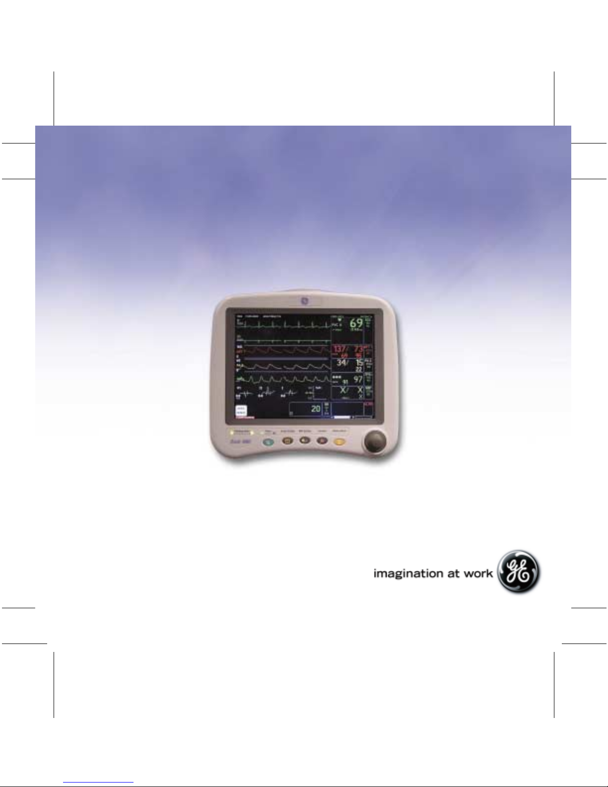
BEDSIDE MONITORING
Dash 3000/4000 V5
TAB
TRIM
COVER &
NON-TAB
TRIM
Quick Reference Guide
© 2004 General Electric Company
PN: 0304-CS-QRGD Rev. A
2018408-010
COVER &
NON-TAB
TRIM
TAB
TRIM
Page 2
BEDSIDE MONITORING
Dash 3000/4000 V5
TAB
TRIM
COVER &
NON-TAB
TRIM
Quick Reference Guide
COVER &
NON-TAB
TRIM
TAB
TRIM
Page 3
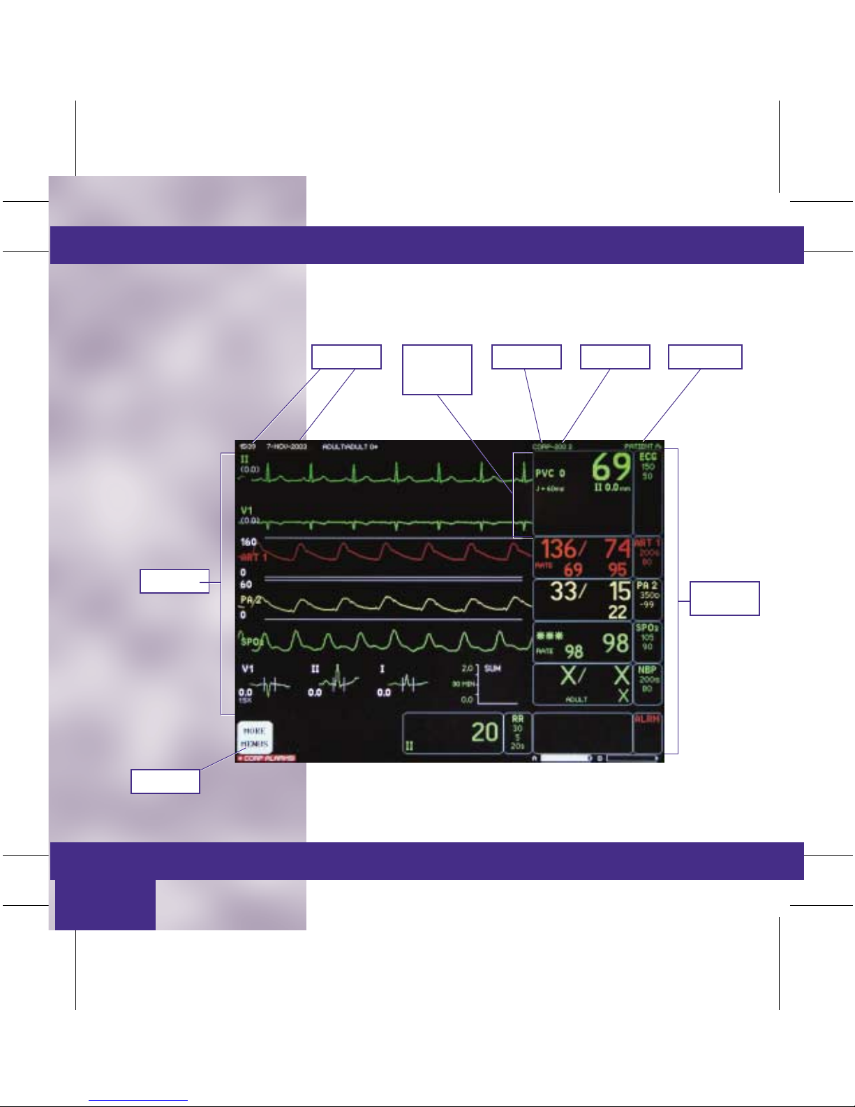
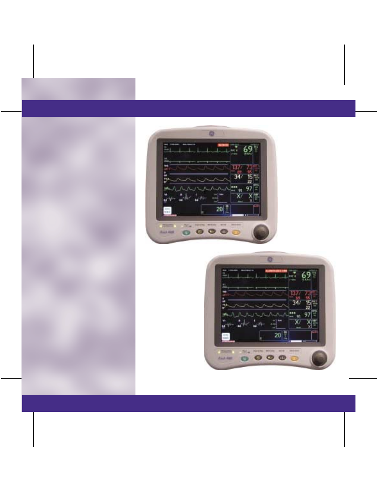
Components
■ Display
• Date
• Time
• Unit Name
• Bed Number
• Patient Name
• Parameter
Window
• More Menus
• Waveforms
Time / Date
ECG
Parameter
Window
Unit Name Bed Number
TAB
TRIM
COVER &
NON-TAB
TRIM
Patient Name
Waveforms
More Menus
Basic Use/
Admit/Discharge
Parameter
Windows
COVER &
NON-TAB
TRIM
TAB
TRIM
Page 4
Basic Use/
Admit/Discharge
The Basics
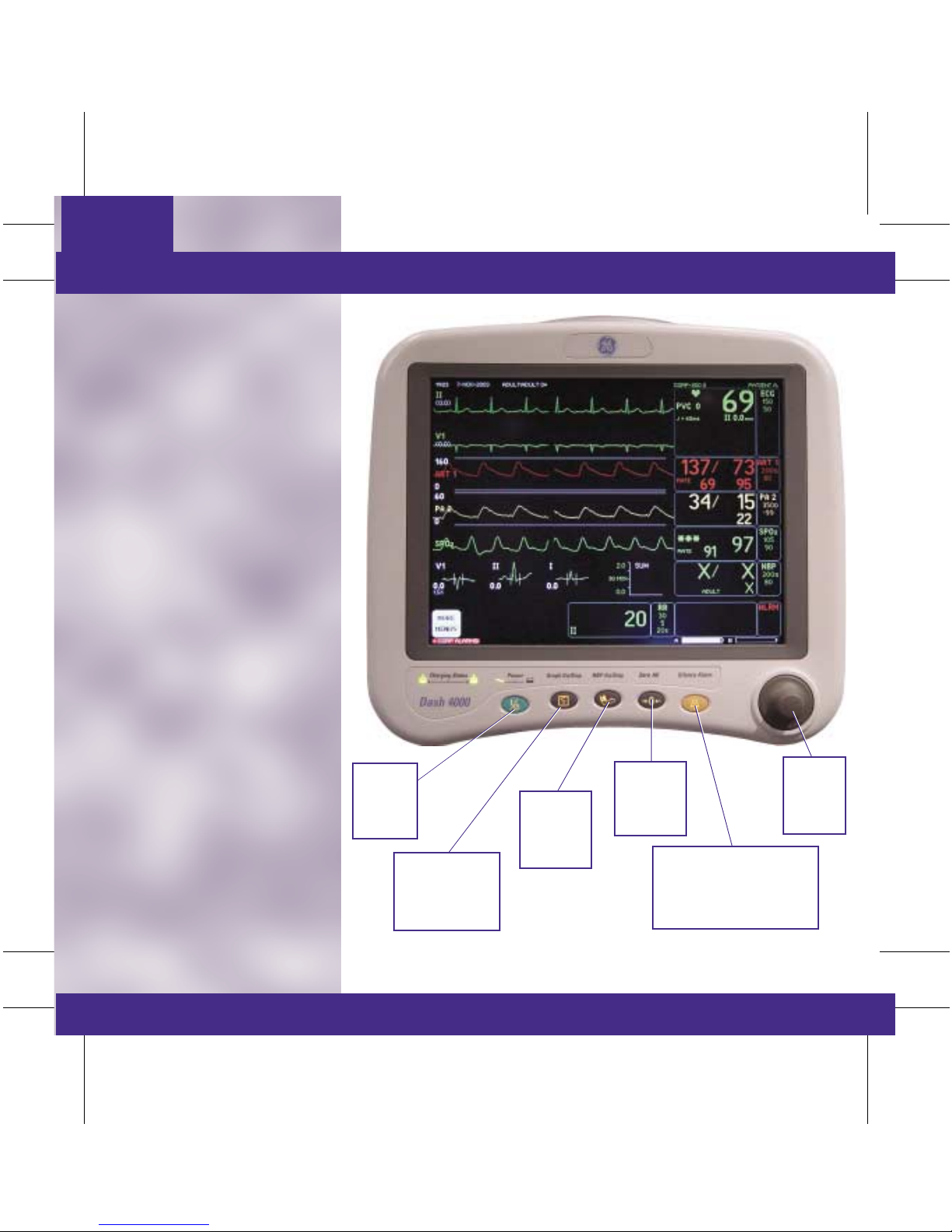
■ Direct Action Keys
■ Operations
• Trim Knob: The Trim Knob
is found on the monitor or
remote control and is used for
highlighting and selecting
menu options.
– Turn the Trim Knob to
highlight desired menu
options.
– Once you have highlighted
the menu option, press to
select.
TAB
TRIM
COVER &
NON-TAB
TRIM
POWER:
Tur ns
Display
On or Off
GRAPH GO/STOP:
Starts and Stops
Manual Strips
and Print Window.
NBP
GO/STOP:
Starts and
Stops NBP.
ZERO ALL:
Zeros
Invasive
Pressures.
SILENCE ALARM:
Silences and Pauses Alarms.
Also Serves as a
Quick Admit Key
TRIM
KNOB:
Turn and
Push.
COVER &
NON-TAB
TRIM
TAB
TRIM
Page 5
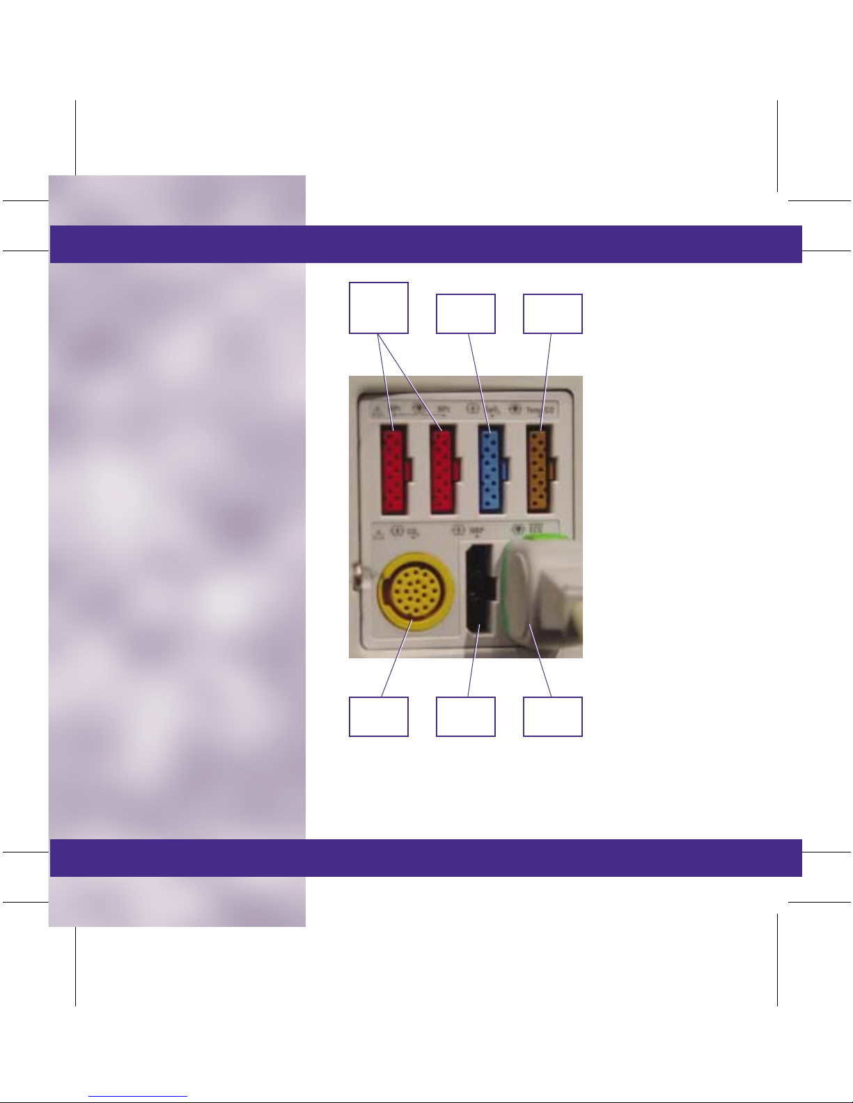
■ Patient Cable Connectors
• All patient cable connectors
are located on the side of the
monitor.
■ Definition of Terms
• Hardwire: This means that
the ECG signal is being
acquired from a cable
attached to the patient and
connected to a bedside
monitor.
• Telemetry: This means that
the ECG signal is being
acquired from a telemetry
transmitter/transceiver. This
patient is able to ambulate
without being limited by a
cable.
• TTX: Refers to a telemetry
transmitter/transceiver.
RED:
Invasive
Pressures
BLUE:
SPO
TAB
TRIM
COVER &
NON-TAB
TRIM
BROWN:
2
CO / Temp
YELLOW:
CO
2
BLACK:
NBP
GREEN:
ECG
COVER &
NON-TAB
TRIM
TAB
TRIM
Page 6
■ Silence Alarm
• Pressing the Silence Alarm key
once will silence an active
alarm for one minute. The
message SILENCED will
appear on the display. Any
new alarm at an equal or
greater priority will sound.
NOTE: If Crisis Alarm Breakthrough is set in defaults, all crisis
alarms will break through Alarm Silence and Alarm Pause.
• Pressing the Silence Alarm key
twice if an alarm is sounding
will start an ALARM PAUSE.
The length of pause will vary
depending on the monitor’s
mode. The message ALARM
PAUSE will appear on the
display.
NOTE: Alarm Pause Lengths:
— Adult ICU Mode: 5 minutes.
— Neonatal ICU Mode: 3 minutes.
— Operating Room Mode: 5 minutes. 15 minutes,
Alarm Paused (permanent pause).
• Alarms will reactivate if the
Silence Alarm key is pressed
again.
• An Alarm Pause will
immediately be activated if
the Silence Alarm key is
pushed in the absence of an
alarm.
TAB
TRIM
COVER &
NON-TAB
TRIM
COVER &
NON-TAB
TRIM
TAB
TRIM
Page 7
Monitor Applications
The bedside monitor can be used in
four different ways depending on
hospital need. Differences between
each application will be apparent in
the monitor’s admit menu.
Standard
This application uses a monitor
mounted in a room. It has only
hardwire capability and does not
accommodate telemetry.
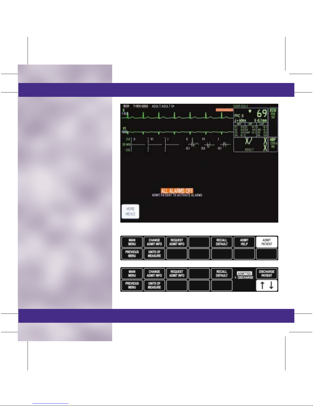
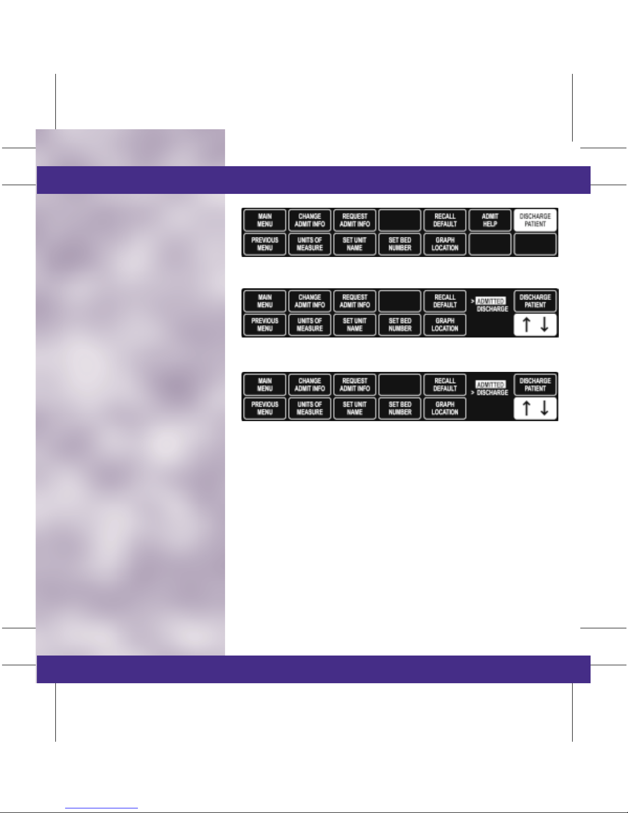
■ To Admit a Patient
• Select MORE MENUS.
• Select ADMIT MENU.
• Select ADMIT PATIENT.
NOTE: The Admit key, on the front of the monitor, can also be
used to admit the monitor.
■ To Discharge a Patient
• Remove all ECG leads from
the patient.
• Select MORE MENUS.
• Select ADMIT MENU.
• Select DISCHARGE
PATIENT.
• Turn the Trim Knob to move
the cursor in front of
Discharge and press to select.
• A message DISCHARGED
and ALL ALARMS OFF will
appear on the display when
the monitor is in a discharged
mode.
TAB
TRIM
COVER &
NON-TAB
TRIM
COVER &
NON-TAB
TRIM
TAB
TRIM
Page 8

■ How to Enter Demographic
Information:
• Select MORE MENUS.
• Select ADMIT MENU.
• Select CHANGE ADMIT
INFO. An information
window with menu options
is displayed.
• Rotate the Trim Knob
control to move the pointer
(>); repeat the press, turn,
press process to enter
characters or make
selections.
• Select RETURN after all
information is entered.
• Select desired option:
SAVE CHANGES or DO
NOT SAVE CHANGES.
TAB
TRIM
COVER &
NON-TAB
TRIM
■ Recall Defaults:
• This menu allows the
clinician to recall previously
named monitor defaults
while monitoring an
admitted patient.
• Up to five sets of defaults
can be programmed.
COVER &
NON-TAB
TRIM
TAB
TRIM
Page 9
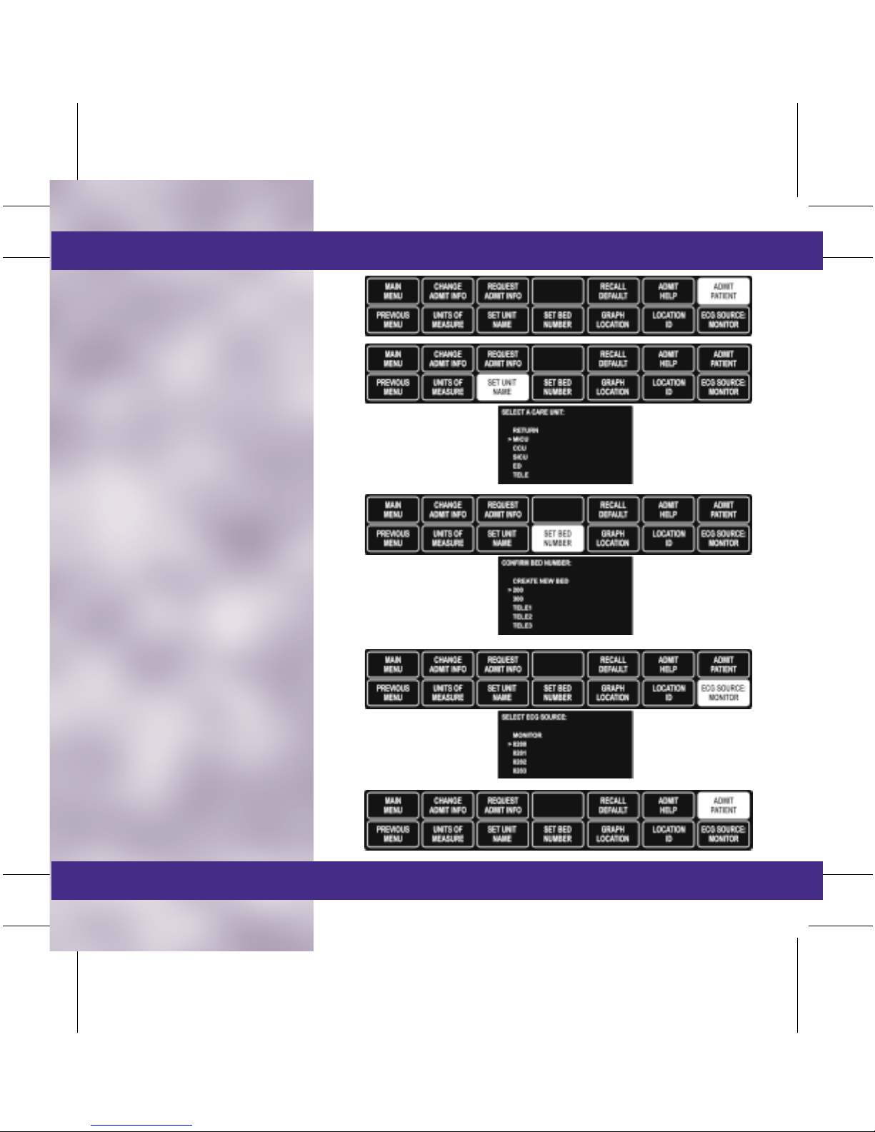
Rover
This application allows the monitor
to be moved or “roved” to the
patient’s bedside. It has only
hardwire capability and does not
accommodate telemetry.
■ To Admit a Patient
• Connect the AC Power source.
• Connect the Network cable.
NOTE: This step is not required when using wireless
Dash monitors. It is required for all other Dash
monitors.
• Push the Power button to
activate the display.
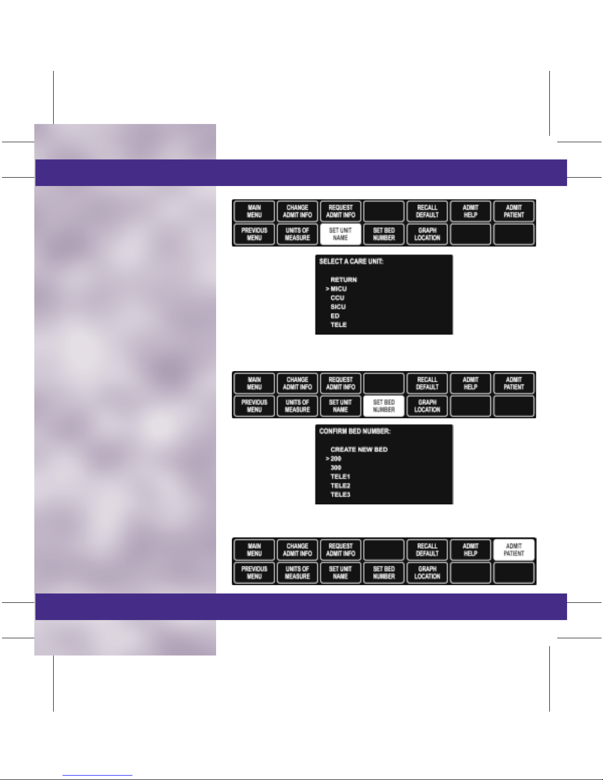
• Select MORE MENUS.
• Select ADMIT MENU.
• Select SET UNIT NAME.
• From the information window,
move cursor in front of the
desired unit.
• Select BED SET NUMBER.
• From the information window,
move cursor in front of the
desired bed number.
• Select ADMIT PATIENT.
NOTE: If the Unit Name or Bed Number windows do not
appear, check that the network cable is connected.
TAB
TRIM
COVER &
NON-TAB
TRIM
COVER &
NON-TAB
TRIM
TAB
TRIM
Page 10
Rover
■ To Discharge a Patient
• Remove all ECG leads from
the patient.
• Select MORE MENUS.
• Select ADMIT MENU.
• Select DISCHARGE
PATIENT.
• Turn the Trim Knob to move
the cursor in front of
Discharge and press to select.
• A message DISCHARGED
and ALL ALARMS OFF will
appear on the display when
the monitor is in a discharged
mode.
NOTE: It is recommended to leave the network cable plugged
in and the Dash display on for two minutes following
discharge (if applicable).
• Push the Power button to turn
the display off.
• Store the monitor with AC
power cord plugged in and
display off.
TAB
TRIM
COVER &
NON-TAB
TRIM
COVER &
NON-TAB
TRIM
TAB
TRIM
Page 11

Combo
This application uses a monitor
mounted in a room, but the ECG
data can be acquired from either a
hardwire cable from the monitor or
a telemetry transmitter/transceiver.
■ To Admit a Patient to
Hardwire
• Select MORE MENUS.
• Select ADMIT MENU.
• Select ADMIT PATIENT.
■ To Change the ECG
Source from Hardwire to
Telemetry
• Select MORE MENUS.
• Select ADMIT MENU.
• Select ECG SOURCE.
• Turn the Trim Knob to move
the cursor in front of the
desired telemetry transmitter/
transceiver number or
Monitor (Discharge Telem)
for hardwire capability from
the information window and
press to select.
TAB
TRIM
COVER &
NON-TAB
TRIM
NOTE: If the Telemetry transmitter/transceiver is being used
for the ECG signal, the TTX number will appear in the ECG
parameter box.
COVER &
NON-TAB
TRIM
TAB
TRIM
Page 12

Combo
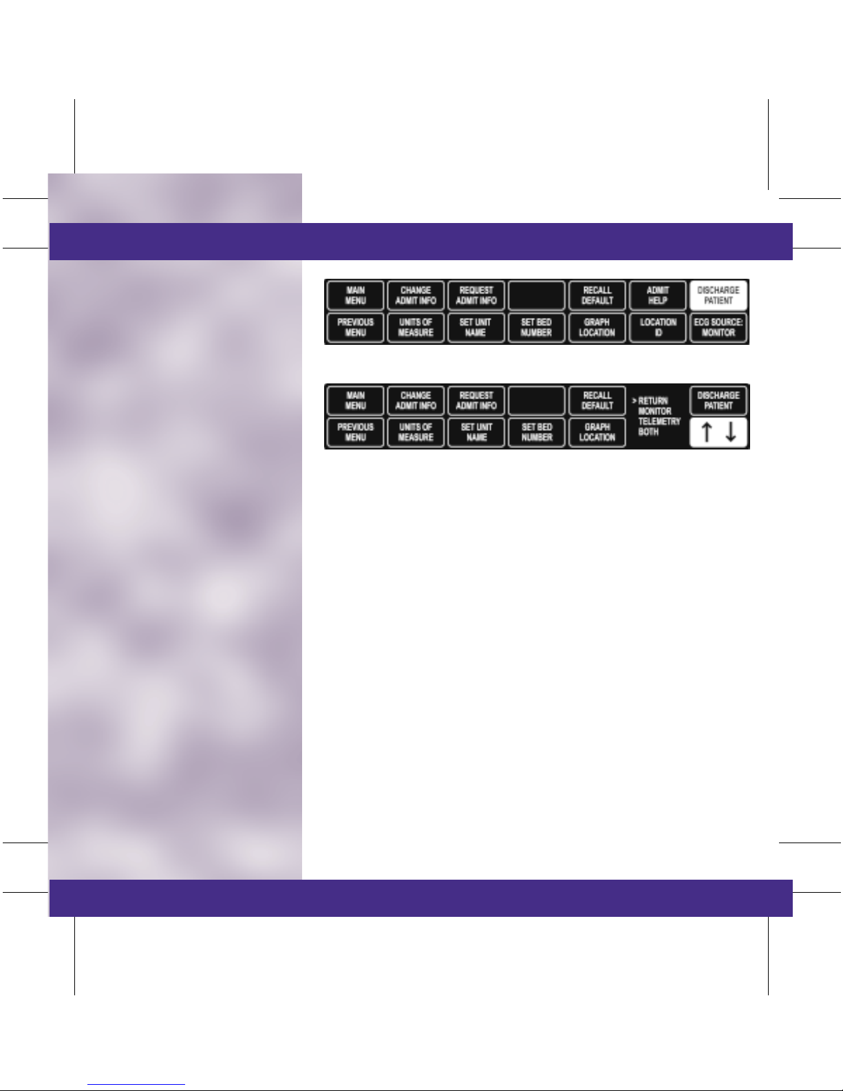
■ To Discharge a Patient:
• Remove all ECG leads from
the patient.
• Select MORE MENUS.
• Select ADMIT MENU.
• Select DISCHARGE
PATIENT.
• Turn the Trim Knob to move
the cursor in front of the
desired discharge option and
press to select.
– Return: Exit to Main Menu.
– Monitor: Discharges only
the bedside monitor.
– Telemetry: Discharges
patient from telemetry.
– Both: Discharges both the
monitor and telemetry.
• A message DISCHARGED
and ALL ALARMS OFF will
appear on the display when
the monitor is in a discharged
mode.
NOTE: When discharging ONLY the bedside monitor, all stored
vital sign data will be deleted. The only data which remain
available will be: HR, ST, PVC, and Alarm Histories.
TAB
TRIM
COVER &
NON-TAB
TRIM
COVER &
NON-TAB
TRIM
TAB
TRIM
Page 13
Rover-Combo
This application combines the
mobility feature of Rover
monitoring with the telemetry
capabilities of Combo monitoring.
■ To Admit a Patient
• Connect the AC Power source.
• Connect the Network cable.
NOTE: This step is not required when using wireless
Dash monitors. It is required for all other Dash
monitors.
• Push the Power button to
activate the display.
• Select MORE MENUS.
• Select ADMIT MENU.
• Select SET UNIT NAME.
• From the information window,
move cursor in front of the
desired unit.
• Select SET BED NUMBER.
• From the information window,
move cursor in front of the
desired bed number.
• Select ECG SOURCE.
• From the information window,
move cursor in front of the
desired transmitter/
transceiver or monitor
(hardwire) and press to select.
NOTE: If the Unit Name, Bed Number or ECG Source windows
do not appear, check that the network cable is connected.
• Select ADMIT PATIENT.
TAB
TRIM
COVER &
NON-TAB
TRIM
COVER &
NON-TAB
TRIM
TAB
TRIM
Page 14
Rover-Combo
■ To Discharge a Patient:
• Remove all ECG leads
from the patient.
• Select MORE MENUS.
• Select ADMIT MENU.
• Select DISCHARGE
PATIENT.
• Turn the Trim Knob to move
the cursor in front of the
desired discharge option and
press to select:
– Return: Exit to Main
Menu.
– Monitor: Discharges only
the bedside monitor.
– Telemetry: Discharges
patient from telemetry.
– Both: Discharges both the
monitor and telemetry.
NOTE: When discharging ONLY the bedside monitor, all stored
vital sign data will be deleted. The only data which remain
available will be: HR, ST, PVC, and Alarm Histories.
• A message DISCHARGED
and ALL ALARMS OFF will
appear on the display when
the monitor is in a discharged
mode.
• Push the Display On/Off
button to turn the display off.
NOTE: It is recommended to leave the network cable plugged
in and the Dash display on for two minutes following
discharge.
• Store the monitor with the AC
power cord plugged in and
the display off.
TAB
TRIM
COVER &
NON-TAB
TRIM
COVER &
NON-TAB
TRIM
TAB
TRIM
Page 15
ECG
■ Skin Preparation and Lead
Placement:
The quality of the signal
received from the electrodes is a
direct result of skin prep and
lead placement.
• Clip or shave hair from
application sites.
• Gently rub the area with a
gauze pad to remove dead
skin cells.
• Cleanse site with alcohol or
mild soap and water.
• Dry skin completely.
• Apply electrodes according
to manufacturers
recommendations.
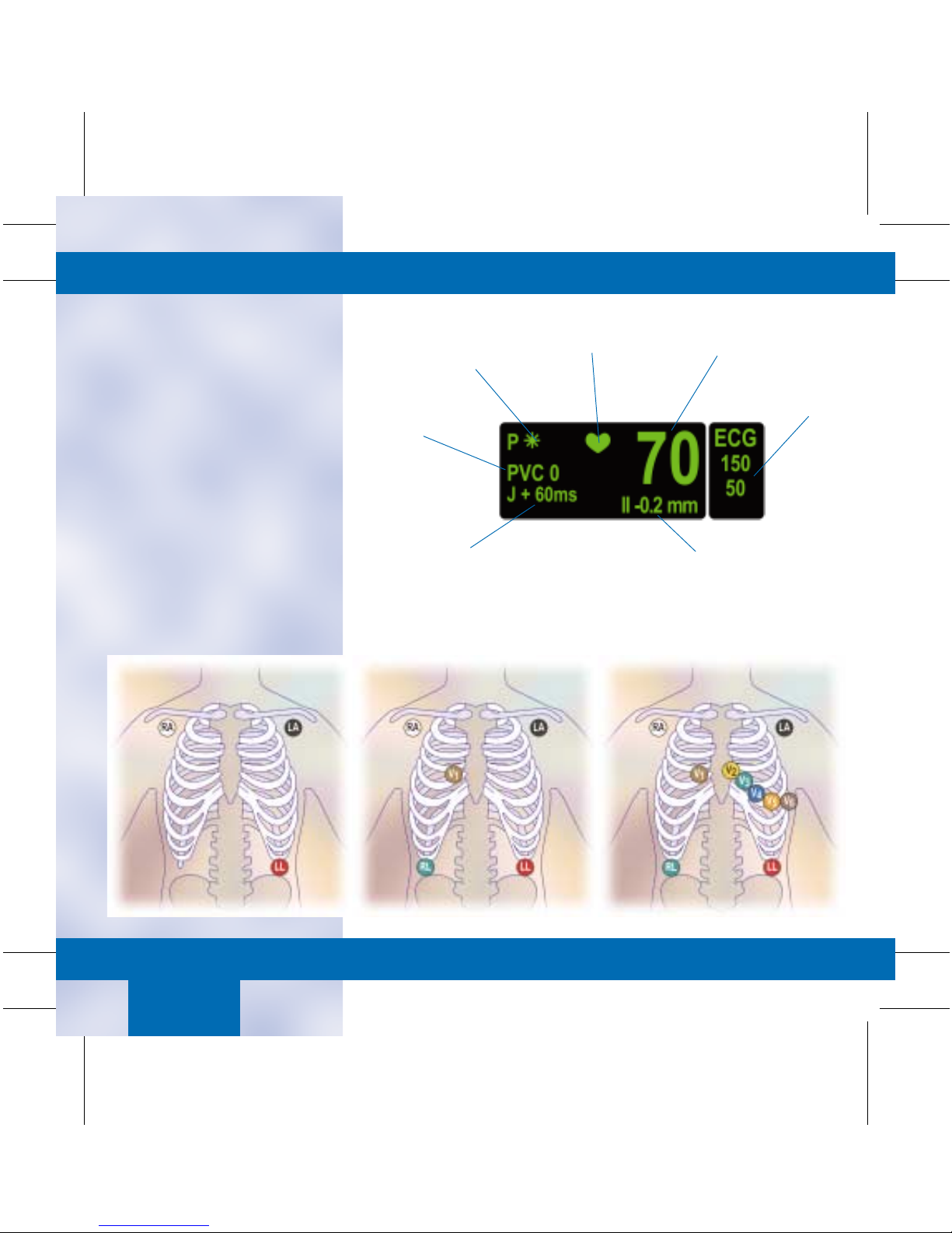
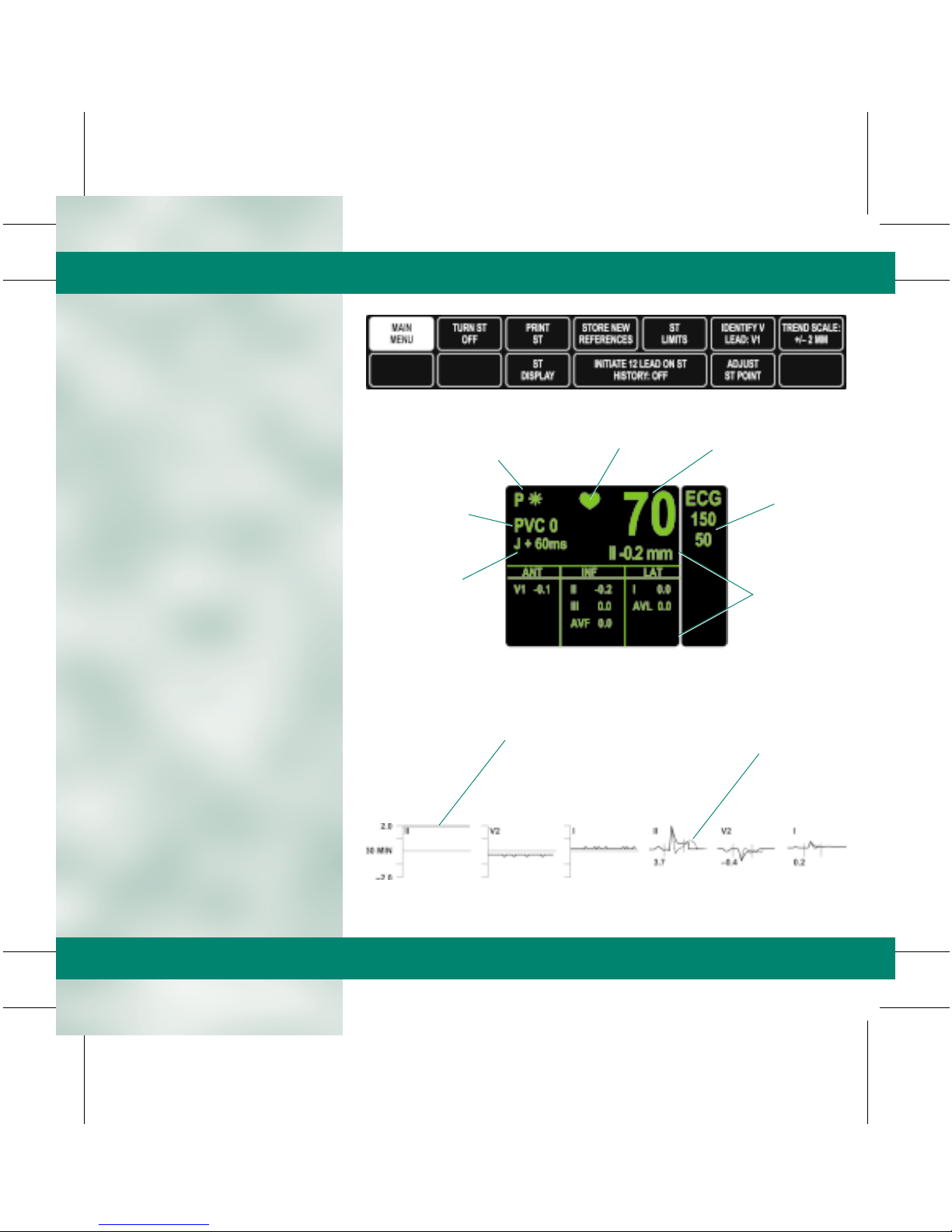
Pace Detection
Indicators
PVC Count
(Full Arrhythmia Only)
ST Measurement
Point
QRS
Indicator
TAB
TRIM
COVER &
NON-TAB
TRIM
Heart Rate
Heart Rate
Alarm Limits
ST Analysis Data
ECG/
Pace
COVER &
NON-TAB
TRIM
TAB
TRIM
Page 16
ECG/
Pace
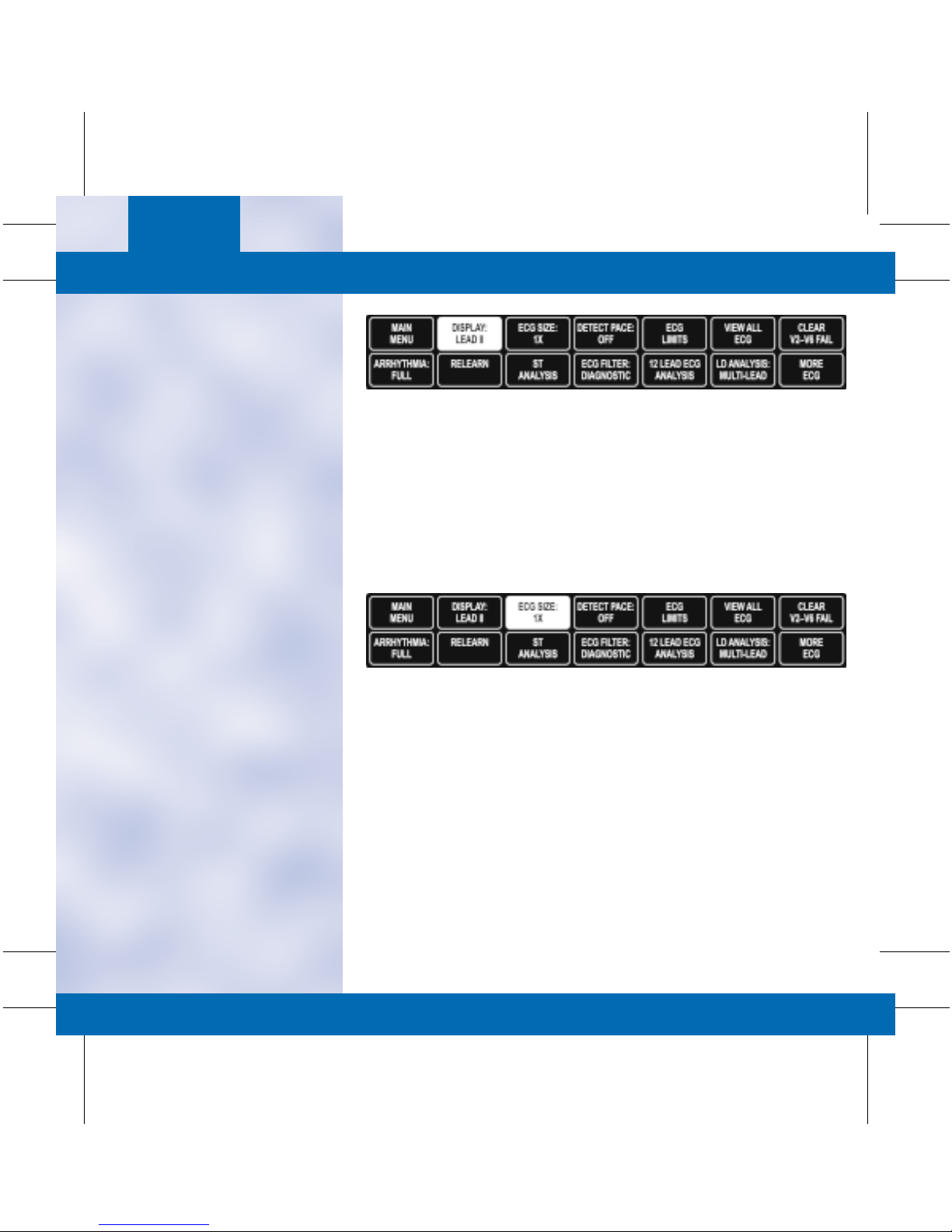
■ Display Lead: Top or first lead
displayed on the bedside and
graphed with alarms and
manual prints.
• To Change the Display Lead:
– Select ECG.
– Select DISPLAY LEAD II.
– A popup menu opens.
– Move the cursor in front of
the desired display lead and
press to select.
– Select MAIN MENU to
exit.
■ Size: Changes the size of all
ECG waveforms displayed and
graphed. 1X is the standard
size.
NOTE: At least a 0.5 millivolt QRS complex at standard size is
needed for beat detection.
• To Adjust ECG Size:
– Select ECG.
– Select ECG SIZE.
– Turn the Trim Knob to
highlight desired selection
and press to select.
– Select MAIN MENU to
exit.
TAB
TRIM
COVER &
NON-TAB
TRIM
COVER &
NON-TAB
TRIM
TAB
TRIM
Page 17
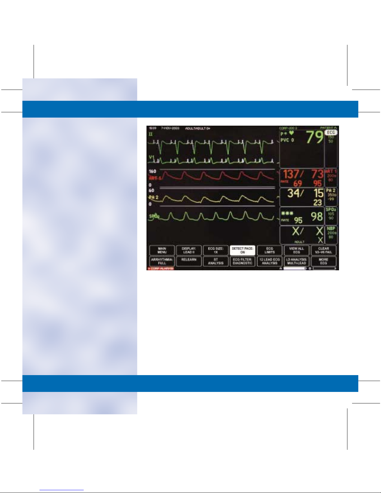
■ Detect Pace: Turns pacemaker
detection On/Off.
• Two different options of
pacemaker modes are
available. The clinician must
judge which mode is best for
each patient. Pace 2 is the
recommended pacemaker
detection mode. Pace 1
should be used if Pace 2 does
not adequately detect
pacemaker spikes.
• To Activate or Deactivate the
Pacemaker Mode:
– Select ECG.
– Select DETECT PACE.
– Turn the Trim Knob in
front of the desired
pacemaker mode and press
to select.
– Select MAIN MENU to
exit.
NOTE: A “P” appears in the ECG parameter window when pace
detection is enabled. An “*” will appear if a paced beat is
detected.
■ Pace 2 Mode: Analyzes
waveforms with the added
capability of minimizing the
chance of counting severe
residual pacemaker energy as a
QRS complex. Pace 2 may not
adequately detect all QRS
morphologies. Arrhythmia calls
such as Asystole or Pause may
be made with heart rate
identified as less than actual.
NOTE: Pacemaker patients should be kept under close
observation.
TAB
TRIM
COVER &
NON-TAB
TRIM
■ Pace 1 Mode: Analyzes the
presence of pacer spikes,
assesses the waveform for
residual pacemaker energy and
determines the presence of an
R-wave following the pacemaker
spike. If an event occurs during
the first few milliseconds
following the spike, it will be
counted as a paced spike.
COVER &
NON-TAB
TRIM
TAB
TRIM
Page 18
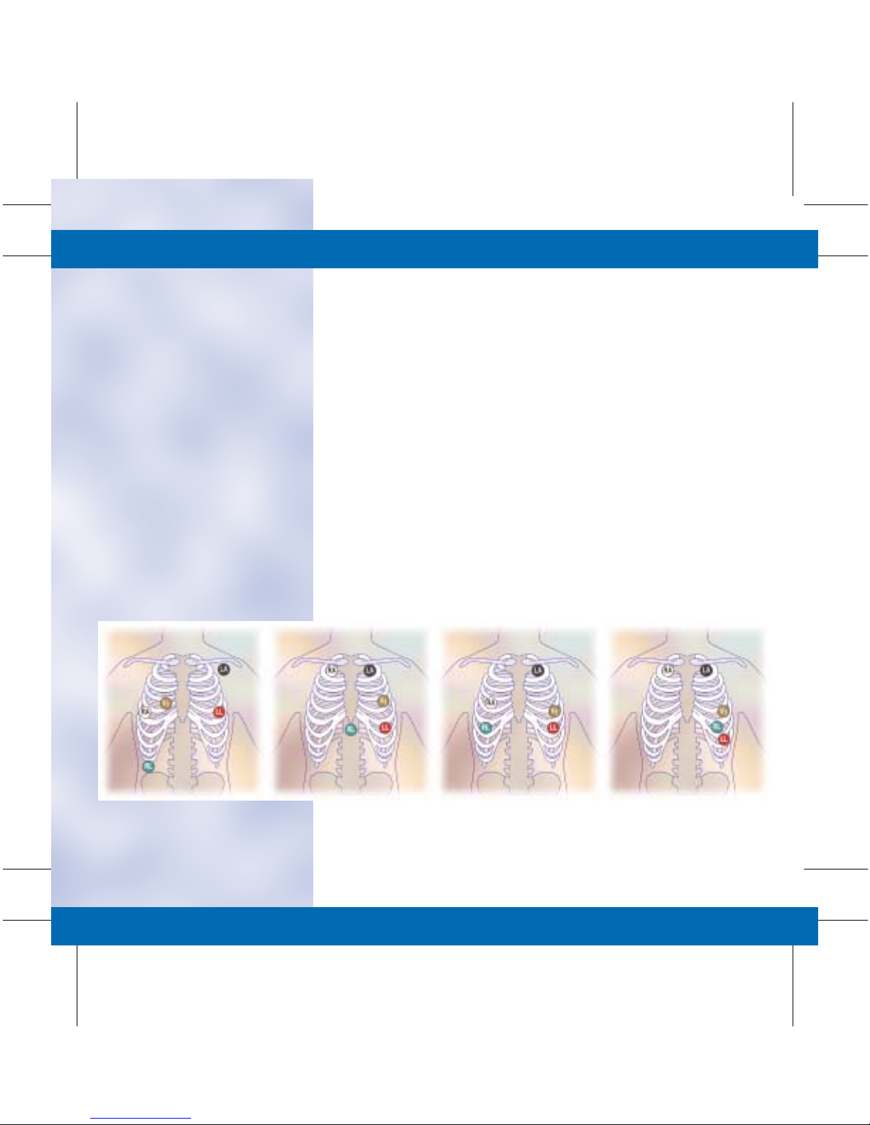
■ Guidelines for Successful
Pacemaker Monitoring:
• Multi-vector pace detection is
determined by simultaneous
analysis of the displayed ECG
Lead and the Vector Lead.
• Adequate pacemaker
detection is directly
dependant on the quality of
the ECG waveform. Proper
skin preparation and
electrode placement are
essential.
• Ensure that the pace detection
mode is activated.
• All detected pacemaker spikes
will appear upright, uniform
and white on the display
screen.
• If the monitor is not
adequately detecting
pacemaker spikes —
as evidenced by heart rate
double counting, pacemaker
spikes not detected, alarms for
low heart rate or asystole —
it is recommended that you
change the electrode
placement to a recommended
configuration.
• After changing electrode
placement, always RELEARN
the ECG waveform.
If adjusting the electrode
placement does not resolve
the detection issue, change
the pace detection mode to
Pace 1 and RELEARN.
TAB
TRIM
COVER &
NON-TAB
TRIM
Recommended Alternative Lead Placements
COVER &
NON-TAB
TRIM
TAB
TRIM
Page 19
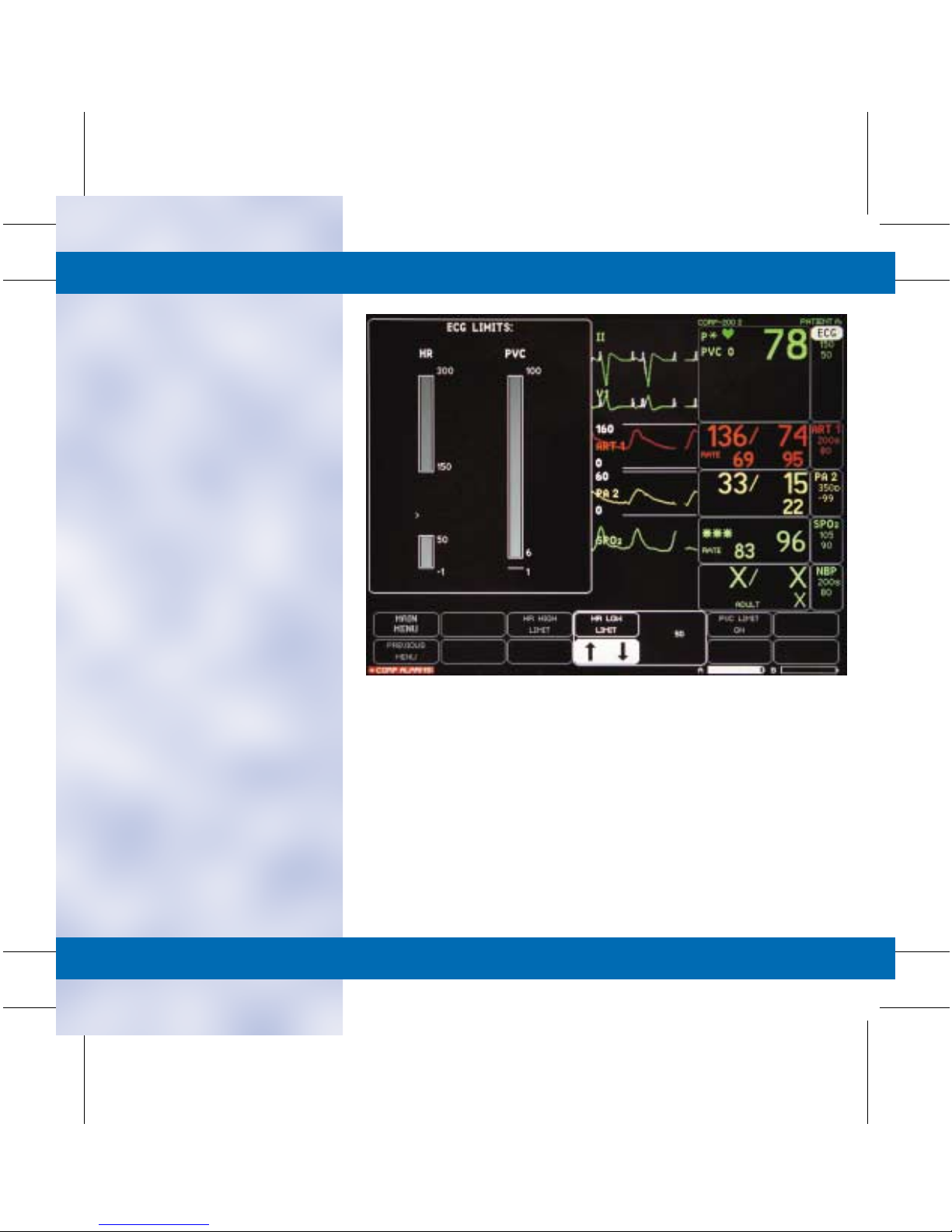
■ Limits:
• To Change the ECG Alarm
Limit:
– Select ECG.
– Select ECG LIMITS.
– Select desired alarm limit.
– Turn the Trim Knob to the
desired alarm limit and
press to select.
– Select MAIN MENU to
exit.
TAB
TRIM
COVER &
NON-TAB
TRIM
COVER &
NON-TAB
TRIM
TAB
TRIM
Page 20
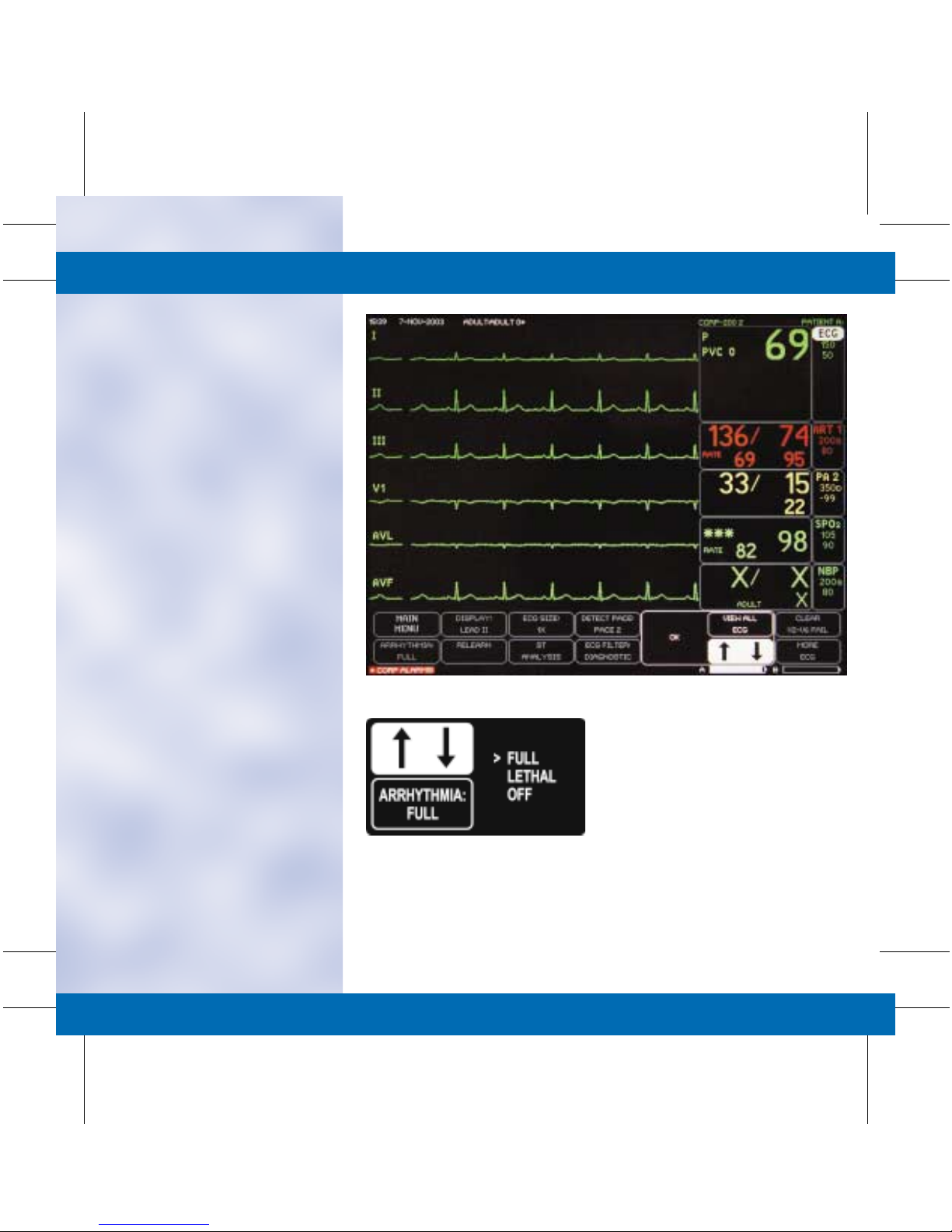
■ View All ECG: Allows six leads
of ECG to be viewed on the
display.
• To View All ECG:
– Select ECG.
– Select VIEW ALL ECG.
– Six waveforms will be
displayed.
– Press GRAPH GO/STOP to
print displayed leads.
– Press the Trim Knob to
remove displayed leads.
– Select MAIN MENU to
exit.
■ Arrhythmia: Arrhythmia
processing can be manually
changed to one of the following
conditions:
• Full: Expands detection to all
arrhythmia conditions
defined by the software level.
• Lethal: Arrhythmia
processing is limited to
Asystole, VFib/VTac and
VTach.
• Off: Disables all arrhythmia
alarms. Parameter alarms
remain active.
• To Change the Arrhythmia
Processing Mode:
– Select ECG.
– Select ARRHYTHMIA.
– Turn the Trim Knob to
move the cursor in front of
the desired arrhythmia
processing mode and press
to select.
– Select MAIN MENU to
exit.
TAB
TRIM
COVER &
NON-TAB
TRIM
COVER &
NON-TAB
TRIM
TAB
TRIM
Page 21
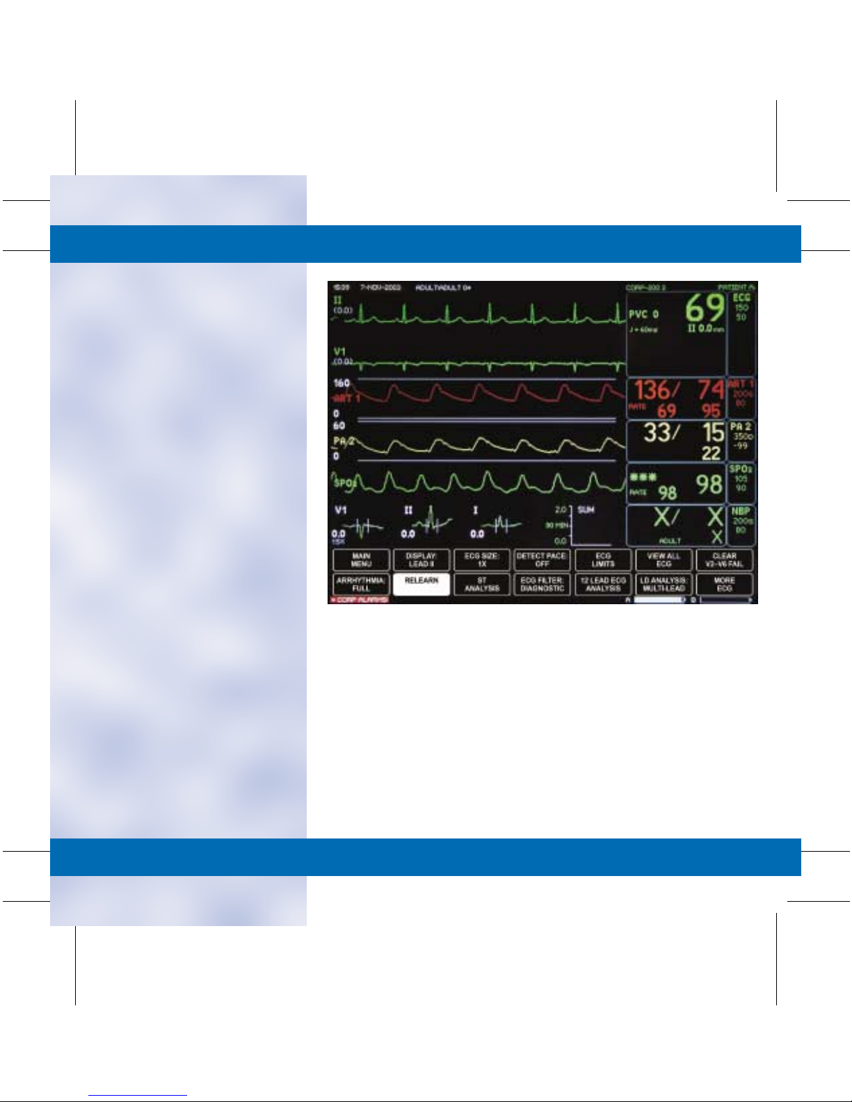
■ Relearn: During ECG
monitoring, it may be necessary
to relearn the ECG waveform if
a change in the patient’s normal
ECG pattern has occurred, or
the electrode placement has
changed.
• A change in the ECG pattern
could result in:
– Incorrect arrhythmia calls.
– Loss of ST measurement.
– Inaccurate heart rate
detection.
• To Relearn the ECG
Waveform:
– Select the ECG parameter
window.
– Select RELEARN.
– The ECG parameter
window will replace the HR
with an “X” and the
message “Learning” will
appear above the display
lead.
– Select MAIN MENU to
exit.
TAB
TRIM
COVER &
NON-TAB
TRIM
■ Turning the ECG Parameter
Off or On: See monitor setup
for details.
COVER &
NON-TAB
TRIM
TAB
TRIM
Page 22
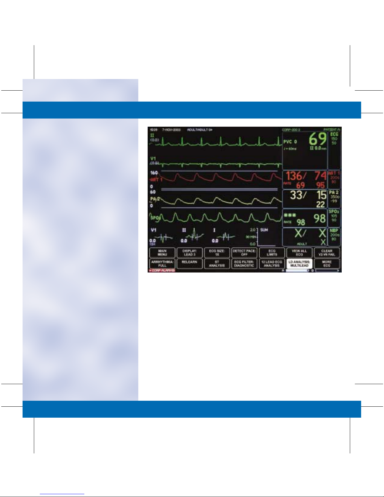
■ Single Lead vs. Multi-Lead:
This option examines ECG
leads utilized for arrhythmia
analysis.
• Multi-Lead Analysis examines
ECG leads I, II, III and V to
help eliminate false alarms
and improve the ability of the
system to:
– Detect beats that occur
isoelectric to a single chest
lead.
– Discriminate artifact that
appears in one lead
compared to other lead
vectors.
– Provides a “Smart Lead
Fail” feature where the
failed lead is identified and,
if available, another lead is
provided for display.
– Continue arrhythmia
processing after a lead
change.
• Single Lead Analysis uses
only the top displayed lead
to process heart rate and
arrhythmia information.
• Single lead analysis can be
beneficial when
troubleshooting heart rate
and arrhythmia alarms.
• To Change to Single Lead
Analysis:
– Select the ECG Parameter
Window.
– Select LD ANALYSIS:
MULTI-LEAD.
– Move the cursor in front of
Single Lead and press to
select.
– Select MAIN MENU to
exit.
TAB
TRIM
COVER &
NON-TAB
TRIM
COVER &
NON-TAB
TRIM
TAB
TRIM
Page 23
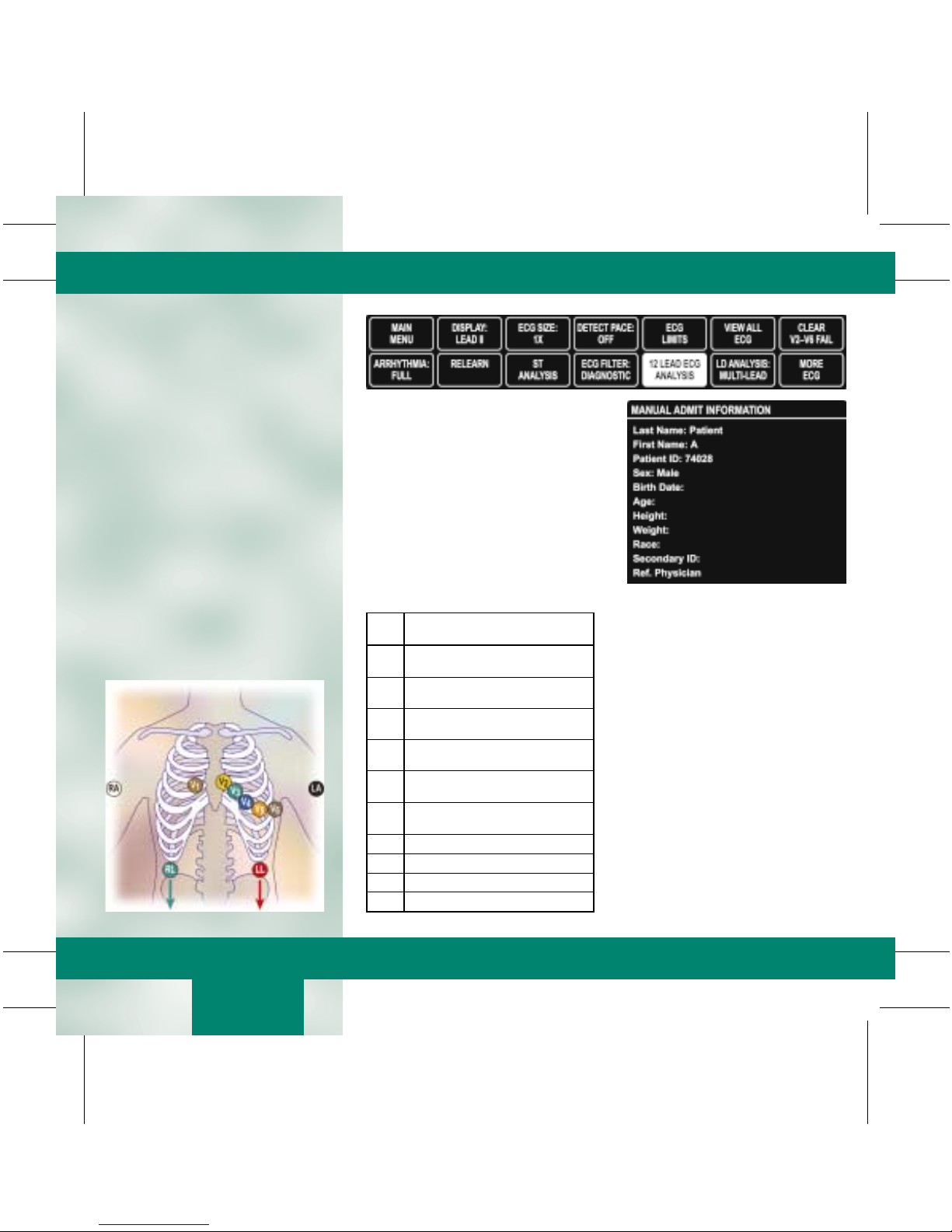
12 Lead ECG Analysis
NOTE: For the most accurate serial comparison, use the same
electrode configuration used on previous analysis.
■ To Obtain a 12-Lead on a
Patient:
• Place patient in a supine
position.
• Correctly identify and apply
all 10 electrodes.
• Select the ECG Parameter
Window.
• Select 12 LEAD ECG
ANALYSIS.
NOTE: Accurate demographics must be entered to ensure
proper analysis.
• Select ADMIT INFO
• Select CHANGE ADMIT
INFO.
Electrode Placement
• Enter Information:
– First Name: Completely
entered.
– Last Name: Completely
entered.
– Patient ID: Facility Specific,
(i.e., Medical Record
Number, Social Security
Number, etc.)
– Sex
Front
Leads
V1 Fourth intercostal space at the right
V2 Fourth intercostal space at the left
V3 Midway, between locations V2 and
V4 Mid-clavicular line in the fifth
V5 Anterior axillary line on the same
V6 Mid-axillary line on the same
LA Left deltoid or left wrist.
RA Right deltoid or right wrist.
LL Left thigh or left ankle.
LA Right thigh or right ankle
12 Lead Electrode Placement
sternal border; right chest.
sternal border; left chest.
V4; left chest.
intercostal space; left chest.
horizontal level as V4; left chest.
horizontal level as V4 & V5; left chest.
– Birth Date
– Age: Correct age impacts
the analysis.
– Height
– Weight
– Location ID: Identifies
origin of 12-lead to MUSE
for transmission.
(Set in defaults. For rover
modes, set in admit menu).
– Site Number: Identifies
hospital to MUSE for
transmission.
(Set in defaults).
NOTE: Depending on facility policy, other fields may be
required; i.e., Technician ID, Optional Field, Order Number.
(continued on next card)
TAB
TRIM
COVER &
NON-TAB
TRIM
COVER &
NON-TAB
TRIM
ST
12 Lead ECG
TAB
TRIM
Page 24

ST
12 Lead ECG
(continued from previous card)
• Select 12 LEAD ECG NOW.
Message appears:
“PERFORMING ANALYSIS.
Please wait…” After 30
seconds, an unconfirmed
12-lead ECG Analysis window
will appear.
• Transmission and/or printing
options include the following:
– Transmit–Print: Send
12 lead for storage to
MUSE and print copy to
laser printer.
– Transmit: Send
12 lead for storage to
MUSE. No printed copy
on unit.
– Print: Print copy to laser
printer on unit. No 12 lead
stored at MUSE.
– Delete: Erase the analysis
without storing or printing.
– Return: Exit to 12-lead
menu.
TAB
TRIM
COVER &
NON-TAB
TRIM
12 Lead is completed. The last 12
lead analysis window is available for
review under REVIEW 12 LEAD
ECG TO TRANSMIT OR PRINT.
COVER &
NON-TAB
TRIM
TAB
TRIM
Page 25
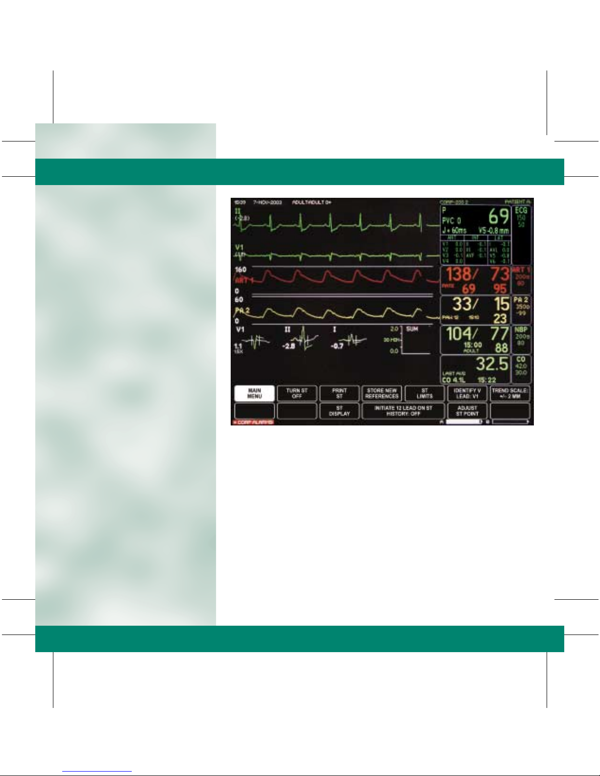
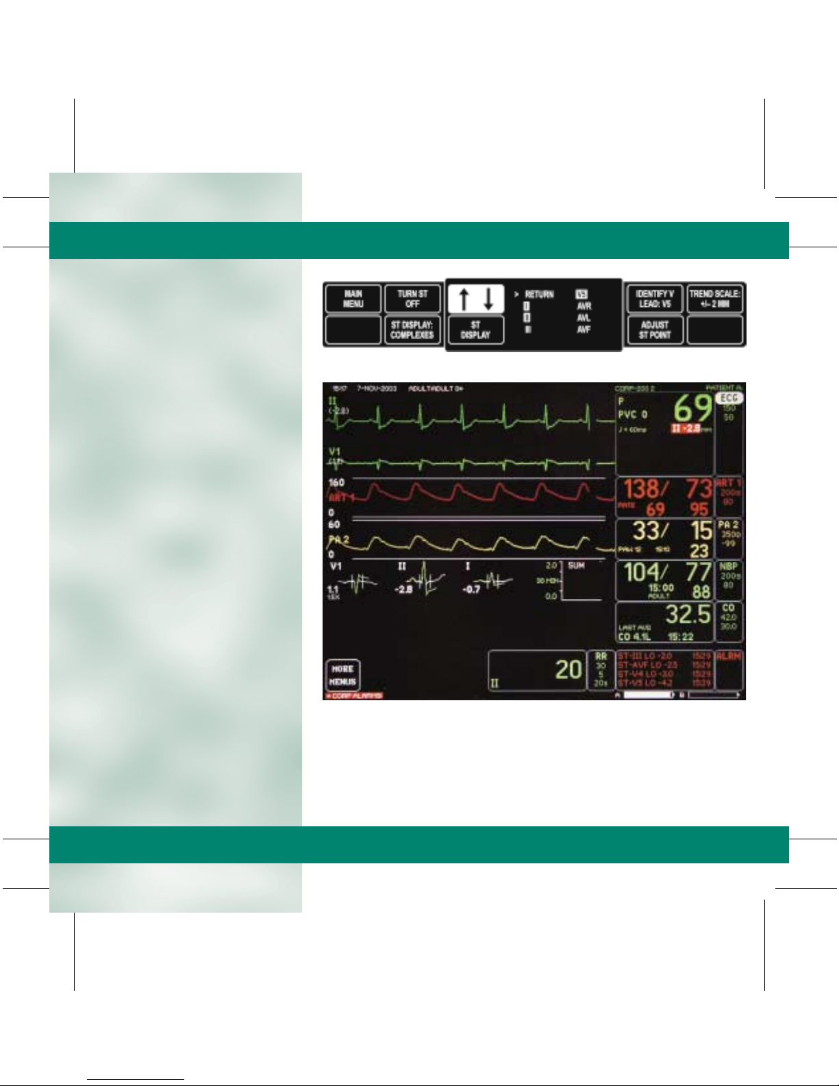
ST Analysis
■ ST Menu Options:
• ST information with trends
and complexes may appear in
a waveform position.
• ST by lead data may appear
in the ECG Parameter
Window.
• The lead with the most
deviation from the isoelectric
line appears in the ECG
window. The ST value is
updated regularly and
changes to the alarming lead
when limits are exceeded.
NOTE: ST options may vary depending on monitor default
configuration.
NOTE: The accuracy of the ST Analysis is dependent on the
placement of the electrodes.
Pace Detection
Indicators
PVC Count
(Full Arrhythmia Only)
ST Measurement
Point
QRS
Indicator
TAB
TRIM
COVER &
NON-TAB
TRIM
Heart Rate
Heart Rate
Alarm Limits
ST Analysis Data
■ ST Trends and Complexes
• The monitor has an ST
display which consists of
three 30-minute ST trends
OR three ECG complexes.
• A reference complex for each
of the selected leads is
displayed for visual reference
purposes when ST is on.
• The current complex is
superimposed (green) over
the reference complex (gray).
Data is outside of
the displayed
scale
The reference
complex is in back
of the current
complex
COVER &
NON-TAB
TRIM
TAB
TRIM
Page 26
■ Turn ST ON/OFF: Turns ST
analysis off and returns to the
main menu.
• To Turn ST Analysis
Program Off:
– Select the ECG parameter
window.
– Select ST ANALYSIS.
– Select TURN ST OFF.
– Display automatically
returns to the Main Menu.
• To Turn ST Analysis
Program On:
– Select the ECG parameter
window.
– Select ST ANALYSIS.
– ST complexes and numerics
automatically appear on the
display.
– Select MAIN MENU to
exit.
■ Store New References:
Displays a new set of reference
complexes on the screen to use
as a visual reference.
• To store new references:
– Select the ECG parameter
window.
– Select ST ANALYSIS.
– Select STORE NEW
REFERENCES.
– Select YES from the popup
menu.
The reference complexes
shown on the display will
now reflect the current
complexes.
– Select MAIN MENU to
exit.
NOTE: Selecting STORE NEW REFERENCE does not affect
actual ST processing, it is for visual reference only.
TAB
TRIM
COVER &
NON-TAB
TRIM
COVER &
NON-TAB
TRIM
TAB
TRIM
Page 27
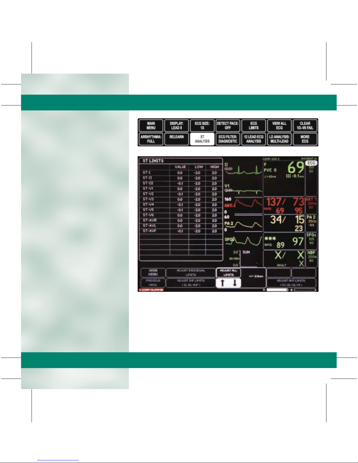
■ ST Limits: Displays a menu
and information window to set
and adjust ST deviation limits.
• To Adjust All ST Limits:
– Select the ECG parameter
window.
– Select ST ANALYSIS.
– Select ADJUST ALL
LIMITS.
– Turn the Trim Knob to the
+ / – desired limit and
press to select.
– All limits are automatically
adjusted in the information
window.
– The monitor adjusts the low
and high limits around the
current value of the lead(s).
– Select MAIN MENU to
exit.
TAB
TRIM
COVER &
NON-TAB
TRIM
COVER &
NON-TAB
TRIM
TAB
TRIM
Page 28
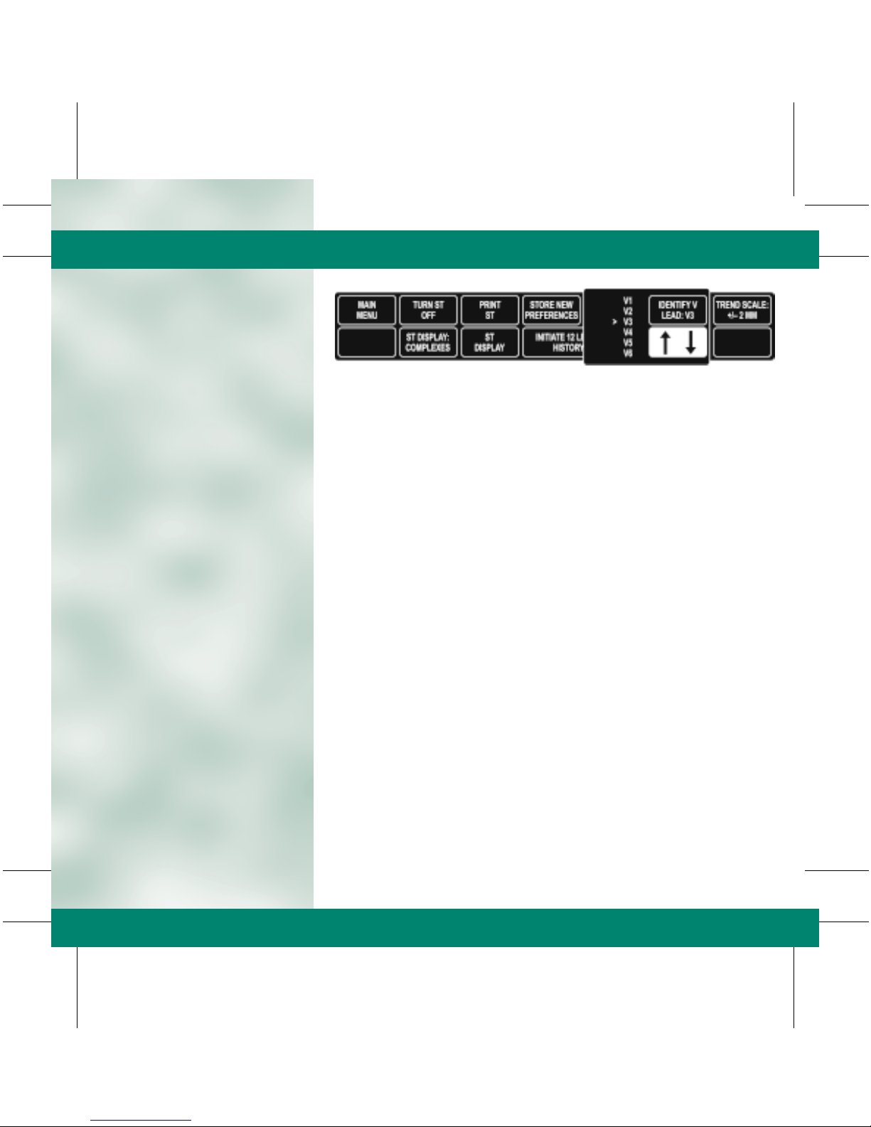
■ Identify V Lead: Identifies the
V Lead being used for ECG and
ST analysis.
• To Change the V Lead:
– Select the ECG parameter
window.
– Select ST ANALYSIS.
– Select IDENTIFY V LEAD.
– Move the cursor in front of
the desired V Lead and
press to select.
NOTE: With a 5-leadwire cable, the V Lead is used in ST
Analysis and arrhythmia analysis.
Changing this label changes the label on the V-lead trend and
complex.
NOTE: With a 10-leadwire cable, the V Lead is used for
arrhythmia analysis only. Changing this label DOES NOT
change the label on the ST display. Use the ST display menu
to change the label.
– Select MAIN MENU to
exit.
TAB
TRIM
COVER &
NON-TAB
TRIM
COVER &
NON-TAB
TRIM
TAB
TRIM
Page 29
■ ST Display: Changes the leads
for the trends and complexes
display.
• To Change the Displayed ST
Leads:
– Select the ECG parameter
window.
– Select ST ANALYSIS.
– Select ST DISPLAY.
– Turn the Trim Knob to
deselect one of the three
selections before selecting
another.
– Select MAIN MENU to
exit.
NOTE: A maximum of three choices can be selected for the ST
Display.
TAB
TRIM
COVER &
NON-TAB
TRIM
COVER &
NON-TAB
TRIM
TAB
TRIM
Page 30

TAB
TRIM
COVER &
NON-TAB
TRIM
COVER &
NON-TAB
TRIM
TAB
TRIM
Page 31

NBP
■ Non-Invasive Blood Pressure
(NBP): Non-invasive blood
pressure is measured using the
oscillometric method. The cuff
is inflated to occlude the artery
and then released in increments.
The monitor determines the
point of maximum pulsation,
which is the mean arterial blood
pressure. The systolic and
diastolic pressures are then
determined.
■ NBP: Display
• NBP Values: Current systolic,
diastolic, and mean values.
• Limits and Units: The upper
and lower systolic alarm limits
and units of measure may be
displayed.
• Countdown Timer: When the
NBP AUTO is selected, the
countdown timer shows the
amount of time remaining
until the next NBP
measurement.
Time of Last
Measurement
and Cuff Size
Countdown
Tim er
Systolic Value
Diastolic Value
Mean Value
TAB
TRIM
COVER &
NON-TAB
TRIM
Limits
and Units
NBP
COVER &
NON-TAB
TRIM
TAB
TRIM
Page 32

NBP
■ NBP Go/Stop: The NBP
Go/Stop button on the monitor
is a quick way to start or stop a
blood pressure measurement.
■ NBP Auto: This option allows
the monitor to be programmed
to take NBP readings
automatically at specific time
intervals.
• To Program NBP for the
Auto Mode:
– Select the NBP.
– Select NBP AUTO.
– A popup menu appears.
– Select MAIN MENU to
exit.
NOTE:
The NBP measurement for the auto option is set in
the monitor defaults and can be timed in two different ways:
1.
Regular Timing:
time interval regardless of the actual clock times.
2.
Clock Sync Timing:
specific clock times.
NBP measurement is taken at a specific
NBP measurement is synchronized to
TAB
TRIM
COVER &
NON-TAB
TRIM
NOTE: Turning the Auto mode Off, then On, restarts the timing
cycle.
NOTE: If a time interval greater than 60 minutes is selected,
AUTO is displayed in the NBP parameter window.
NBP GO/STOP:
Starts and Stops NBP.
COVER &
NON-TAB
TRIM
TAB
TRIM
Page 33

■ Review NBP: The monitor can
store up to 96 NBP readings for
review.
• To Review NBP Readings:
– Select the NBP.
– Select REVIEW NBP.
– An information window is
displayed.
– Select VIEW NEWER/
VIEW OLDER from the
menu options to obtain all
data.
– Press the GRAPH GO/
STOP button on the
monitor to print displayed
vital signs.
– Select MAIN MENU to
exit.
■ NBP Limits: Allows
NBP alarm limits to
be adjusted.
• To Change NBP
Limits:
– Select the NBP.
– Select NBP
LIMITS.
– Select the
desired NBP
limit.
– Turn the Trim
Knob to the
desired limit
and press to
select.
– Select MAIN
MENU to exit.
NOTE: The above steps apply to changes
made to systolic, diastolic and mean NBP
limits.
TAB
TRIM
COVER &
NON-TAB
TRIM
COVER &
NON-TAB
TRIM
TAB
TRIM
Page 34

■ Cuff Size: The cuff size option
determines the initial inflation
pressure. This option sets the
monitor for the appropriate cuff
inflation. Three options are
available:
• Adult: 160 mmHg.
• Pediatric: 140 mmHg.
• Neonatal: 125 mmHg.
With additional blood pressure
measurements the cuff inflation
pressure is 30 mmHg for Adults
and 25 mmHg for Pediatric/
Neonatal over the last systolic
blood pressures.
• To Change the Cuff Size:
– Select the NBP.
– Select CUFF SIZE.
– Move the cursor in front of
the desired cuff size and
press to select.
– Select MAIN MENU to
exit.
NOTE: The cuff size is automatically set if the patient’s age is
entered in the Admit Menu.
■ Clear NBP Reading: This
option removes the current NBP
reading from the parameter
window and vital signs history.
An “X” will replace the numeric
values in the parameter window
if no previous NBP reading is
available.
• To Clear NBP Reading in the
Parameter Window:
– Select the NBP.
– Select CLEAR NBP
READING.
– Xs will be placed in the
parameter window.
– Select Main Menu to exit.
NOTE: Clearing the NBP reading also removes the value from
the vital signs history.
NOTE: The NBP values change to Xs if no NBP monitor has
taken place for two hours in the Adult ICU mode, 15 minutes in
Operating Room mode and 12 hours in Neonatal ICU mode.
TAB
TRIM
COVER &
NON-TAB
TRIM
COVER &
NON-TAB
TRIM
TAB
TRIM
Page 35

SPO
2
■ SPO
monitoring is a
2
non-invasive technique used to
measure the amount of
oxygenated hemoglobin and
pulse rate by measuring
absorption of selected
wavelengths of light.
■ To activate SPO
securely connect the SPO
monitoring,
2
cable
2
into the appropriate blue port
on the Dash monitor. The SPO
2
parameter window will
automatically appear once the
probe is connected to the
SPO
2
cable and plugged into the
monitor.
■ To discontinue SPO
2
monitoring, remove the cable
from the monitor or disconnect
the SPO
The SPO
probe from the cable.
2
window will be
2
removed from the display.
NOTE: Correct probe placement and patient movement may
affect SPO2 signal quality and displayed numeric value.
Good clinical practice includes proper probe placement and
maintenance of probe position on the finger to prevent false
SPO2 readings from ambient light interference.
■ There are three indications from
the monitor that verify the
quality of the data being
displayed:
• Signal Strength Indicators:
– Three asterisks (***) =
Good signal strength.
– Two asterisks (**) =
Adequate signal strength.
– One asterisk (*) =
Poor signal strength.
• Quality of a Good SPO
Waveform:
– Noise or artifact may be
due to poor probe
placement or patient
movement.
2
Signal
Strength
Indicator
SPO
2
Value
Limits
and Units
Pulse Rate
Value
– Frequent, erratic changes in
the value or waveform may
indicate a poor signal.
NOTE: When using Masimo technology, the waveform cannot
be utilized as a quality indicator due to the fact that the
motion artifact is filtered.
• The Stability of the SPO
2
Numeric Value:
– Compare the heart rate in
the SPO
parameter
2
window with the heart rate
in the ECG parameter
window to confirm accuracy.
NOTE: It is critical to observe all three indicators at the same
time.
TAB
TRIM
COVER &
NON-TAB
TRIM
COVER &
NON-TAB
TRIM
SPO
2
TAB
TRIM
Page 36

■ Patient Preparation for SPO
2
Monitoring:
• Choose the probe that is best
suited for your patient’s
needs: ear, finger, disposable,
reusable, etc.
• Clean the surface of the probe
before and after each patient
use.
• Following the instructions
provided with the probe,
correctly position and attach
the probe to your patient.
• When a Masimo sensor is
repositioned at any time,
disconnect the cable from the
sensor before repositioning.
• Reconnect the sensor to the
cable after proper patient
preparation and placement.
SPO
2
■ It is Important to be Aware
of the Following when
Monitoring SPO2:
• A poor SPO2 signal may result
if the probe detector is
exposed to strong ambient
light.
• When securing the probe,
ensure nothing is blocking the
probe light detector.
• Prolonged monitoring may
require changing the probe
site periodically. Monitor the
probe site. Move the probe if
there is any sign of skin
irritation or impaired
circulation.
• Change the probe site at least
EVERY FOUR HOURS to
prevent skin breakdown. With
neonate, you may need to
reduce application periods to
half the recommended time.
TAB
TRIM
COVER &
NON-TAB
TRIM
COVER &
NON-TAB
TRIM
TAB
TRIM
Page 37

■ The Dash monitor incorporates
several different technology
options for interpreting SPO
values:
• Masimo Set
• Nellcor (Oxismart XL)
• GE
■ All SPO
technologies include
2
the following menu options:
• Size: Adjusts the size of the
displayed SPO2 waveform.
The default size is 1X.
To Change the Size:
– Select SPO
.
2
– Select SIZE.
– Turn the Trim Knob to
highlight the desired size
and press to select.
– Select MAIN MENU to
exit.
• Rate: A pulse rate is derived
from the SPO
signal and is
2
displayed in the parameter
window.
To Turn the Displayed Rate
On/Off:
– Select SPO
.
2
– Select RATE.
– This menu option directly
turns the rate option On or
Off.
– Select MAIN MENU to
exit.
2
SPO2 Menu — GE and Nellcor Probes
■ SPO
Rate Volume: The rate
2
volume turns on a tone that
sounds each time an SPO
pulse
2
is detected. This is a variable
pitch tone which changes as the
patient’s saturation level
changes. A drop in saturation
results in a change in pitch of
the tone.
• To Change the Rate Volume:
– Select SPO
.
2
– Select RATE VOLUME.
– Turn the Trim Knob to the
desired SPO
volume and
2
press to select.
– Select MAIN MENU to
exit.
NOTE: Turning the SPO2 rate volume on automatically turns
the QRS volume off and vice-versa.
NOTE: When two SPO2 sites are being monitored, the rate
volume can only be turned on for one site at a time.
■ SPO
Limits: Allows SPO
2
2
percent and rate alarm limits to
be adjusted.
• To Change SPO
– Select SPO
– Select SPO
– Select the desired SPO
Limits:
2
.
2
LIMITS.
2
2
limit.
– Turn the Trim Knob to the
desired SPO
limit and
2
press to select.
– Select MAIN MENU to
exit.
■ Persistent SPO
allows the SPO
2
2
parameter box to remain on the
display after the SPO
cable has
2
been disconnected. The
parameter box displays PROBE
OFF PATIENT the cable is
disconnected and an alarm
sounds at both the monitor and
central station. This option may
be turned on or off in the SPO2
menu if enabled in the defaults.
NOTE: The type of SPO2 technology available is based on
equipment purchased.
TAB
TRIM
COVER &
NON-TAB
TRIM
COVER &
NON-TAB
TRIM
TAB
TRIM
Page 38

■ SPO
— Masimo SET allows the
2
sensitivity and averaging times
to be adjusted:
• Sensitivity options include:
– Normal, for routine patient
monitoring purposes.
– Maximum for improved low
perfusion performance and
for faster tracking of SPO
changes.
– Averaging menu options
determine how many
seconds the collected SPO
information is averaged.
Options for averaging times
are: 2, 4, 8, 10, 12, 14, or
16 seconds.
TAB
TRIM
COVER &
NON-TAB
TRIM
SPO2 Menu — Masimo SET Probes
■ Rejuvenating the Adhesive
Properties of the Disposable
2
2
Saturation Probe:
• Rejuvenate the probe at least
once per shift and PRN.
• Rub the adhesive sides of the
probes with an alcohol
preparation pad.
• After the probe has dried for
at least one minute, replace it
on the site.
NOTE: It is recommended that the adhesive tapes be changed
with every site change. Adhesive tape can not be rejuvenated.
COVER &
NON-TAB
TRIM
TAB
TRIM
Page 39

Respiratory Rate
■ Respirations are detected by
measuring thoracic
impedance. Respirations can
be monitored in Lead I for
chest breathers or Lead II for
abdominal breathers.
• To Change the Respiratory
Lead:
– Select RESPIRATION.
– Select LEAD.
– This option switches
between Lead I and
Lead II.
– Select MAIN MENU to
exit.
NOTE: Changing the leads automatically starts the relearning
process.
■ Relearn Respiration: This
option may be necessary if
the patient’s breathing
pattern has changed or the
monitor is not calculating the
respiratory rate correctly.
This process takes eight
breaths to complete.
• To Relearn the Respiration:
– Select RESPIRATION.
– Select RELEARN.
– A learning message will
appear in the respirations
parameter window.
– Select MAIN MENU to
exit.
Breath Indicator
Lead Monitored
Upper Chest Breathers — Lead I Abdominal Breathers — Lead II
Expiration MarkerInspiration Marker
Example of a Good Respiratory Waveform
Respiration Rate
Limits
and Units
TAB
TRIM
COVER &
NON-TAB
TRIM
COVER &
NON-TAB
TRIM
Respirations /
Temp
TAB
TRIM
Page 40

■ Sensitivity: The monitor
automatically sets the
detection sensitivity at 40% of
the average amplitude. The
sensitivity may need to be
changed due to varying
amplitudes or artifact. The
lower the percentage, the
greater the detection
sensitivity.
• To Change the Sensitivity:
– Select RESPIRATIONS.
– Select SENSITIVITY.
– Turn the Trim Knob to the
desired percent and press
to select.
– Select MAIN MENU to
exit.
NOTE: The RELEARN option will return the sensitivity to 40%.
TAB
TRIM
Respirations /
Temp
COVER &
NON-TAB
TRIM
■ Respiration Limits:
• To Change the Respiration
Limits:
– Select RESPIRATIONS.
– Select the desired
respiratory rate limit.
– Turn the Trim Knob to the
desired respiratory rate and
press to select.
– Select MAIN MENU to
exit.
COVER &
NON-TAB
TRIM
TAB
TRIM
Page 41

Temperature
■ Temperature monitoring can
be done using multiple sites
with internal or external
temperature sensors. The
temperature sites are
identified in the parameter
window as T1 and T2. Only
numeric information is
displayed in the temperature
parameter window.
• Temperature menu options
include:
– T1: This turns monitoring
ON or OFF at temperature
site 1.
– T2: This turns monitoring
ON or OFF at temperature
site 2.
– Units: Switches the units of
measure between Celsius
and Fahrenheit.
• To Change the Temperature
Limits:
– Select TEMPERATURE.
– Select T1 or T2.
– Turn the Trim Knob to the
desired temperature limit
and press to select.
– Select MAIN MENU to
exit.
Temp Value
Temp Sites and Units
TAB
TRIM
COVER &
NON-TAB
TRIM
Temp Limits
for One Site
COVER &
NON-TAB
TRIM
TAB
TRIM
Page 42

TAB
TRIM
COVER &
NON-TAB
TRIM
COVER &
NON-TAB
TRIM
TAB
TRIM
Page 43

Invasive Pressures
■ The invasive pressure labels
are displayed on the monitor
with a number (1 – 4). These
numbers identify the location
in the Dash monitor.
A maximum of six waveforms
and eight parameters can be
displayed on the monitor
when using individual scale
mode.
■ Invasive Pressure —
Insertion.
• To activate invasive pressure
monitoring, securely connect
the transducer cable into the
appropriate red port on the
side of the Dash monitor.
– The invasive parameter
window will automatically
appear once the cable is
plugged into the Dash
monitor.
– To discontinue invasive
monitoring, remove the
cable from the monitor.
The parameter window
will be removed from
the display.
• Preset names are assigned
to each pressure port:
– BP 1: Arterial Line
– BP 2: PA Line
NOTE: Up to two additional Invasive Pressures can be
monitored when using bifurcated cable plugged into the
invasive ports. (Available with Masimo only).
ART
BP 1
ART
BP 2
TAB
TRIM
COVER &
NON-TAB
TRIM
COVER &
NON-TAB
TRIM
Invasive Pressure /
PA
TAB
TRIM
Page 44

Pressure Menu Options:
■ Invasive Pressures —
Zeroing: In order to obtain
accurate pressure
measurements, it is important
to zero the transducers.
Transducers can be zeroed all
at once or individually.
• To Zero Pressure
Transducers:
– Open the transducers to air.
– Press the ZERO ALL
button on the monitor.
– Verify the zero reference is
established.
– Close the transducer to air.
Once the transducer is
closed, the pressure
numerics will be displayed.
NOTE: Transducers can be zeroed individually under the
appropriate parameter window menu option labeled ZERO.
NOTE: A Smart BP feature is found in ART and FEM pressure
menus. This program is designed to reduce nuisance alarms
associated with zeroing the transducer, drawing blood, etc.
The user is allowed 14 seconds for zeroing transducers and
two minutes for drawing blood before the alarms are
activated.
TAB
TRIM
Invasive Pressure /
PA
COVER &
NON-TAB
TRIM
ZERO ALL:
Zeros Invasive
Pressures.
COVER &
NON-TAB
TRIM
TAB
TRIM
Page 45

■ Invasive Pressures — Scale:
• To Change the Scale of the
Pressure Waveform:
– Select the desired pressure
parameter window.
– Select SCALES.
– A popup menu opens
indicating the available
options.
– Move the cursor in front of
the desired scale and press
to select.
– Select MAIN MENU to
exit.
NOTE: AUTO is an option only if the pressure has been zeroed.
Auto-scaled waveforms graph differently than displayed.
■ Invasive Pressures —
Cursor:
• The cursor option places a
moveable, dashed, horizontal
line across the pressure
waveform to give accurate
values at selected points on
the pressure waveform.
Numeric data is displayed to
the right of the cursor.
• To Use the Cursor Option:
– Select the desired pressure
parameter window.
– Select CURSOR.
– A popup menu opens
indicating the available
options.
– Turn the Trim Knob to
move the cursor and press
to select.
– Select MAIN MENU to
exit.
TAB
TRIM
COVER &
NON-TAB
TRIM
• To Remove the Cursor from
the Waveform:
– Select the desired pressure
parameter window.
– Select CLEAR CURSOR.
– This is a direct action menu
option.
– Select MAIN MENU to
exit.
COVER &
NON-TAB
TRIM
TAB
TRIM
Page 46

■ Invasive Pressures —
Smart BP:
• Smart BP is a feature found in
the ART and FEM pressure
menus that reduces nuisance
alarms associated with zeroing
the transducer, fast flushing
and drawing blood.
• To Turn Smart BP On or Off:
– Select ART or FEM
parameter window.
– Select SMART BP and
press to select.
– On/Off status is noted in
the menu option.
– Select MAIN MENU to
exit.
TAB
TRIM
COVER &
NON-TAB
TRIM
Smart BP
■ Disconnect Alarm:
• A feature found in the ART
and FEM pressure menus.
• If the mean pressure falls
below 25 mmHg and the
disconnect alarm is on, a
Warning Alarm sounds and
the message
DISCONNECTED is
displayed in the parameter
window.
• Check the patient
immediately in the event the
catheter has dislodged.
Disconnect Alarms
COVER &
NON-TAB
TRIM
TAB
TRIM
Page 47

■ Graph BP Waveform
• To Graph Waveforms
(without ECG lead):
– Select MORE MENUS.
– Select MONITOR SETUP.
– Select GRAPH SETUP.
– Select GRAPH BP
INVASIVE.
– Highlight desired
waveforms to be graphed.
– Highlight GRAPH.
– Select MAIN MENU to
exit.
– Press the GRAPH GO/
STOP button on the
monitor to stop the graph.
NOTE: This feature is also available in the PA Insert/Wedge
menu.
■ Invasive Pressures —
Limits:
• To Change Invasive Line
Pressure Limits:
– Select the appropriate
parameter window.
– Select LIMITS.
– Select the appropriate limit
(systolic, diastolic or mean).
– Turn the Trim Knob to
the desired limit and press
to select.
– Select MAIN MENU to
exit.
■ Invasive Pressures —
Change Names:
• Be sure that the
invasive pressure
parameter window is
labeled correctly.
Having the invasive
pressure port named
properly is important
for proper waveform
processing and
scaling.
• To Change the Name:
– Select the desired
pressure parameter
window.
– Select NAME
CHANGE.
– A popup menu
opens, indicating
the available
options.
– Turn the cursor in
front of the desired
name and press to
select.
– Select MAIN
MENU to
exit.
TAB
TRIM
COVER &
NON-TAB
TRIM
Graph BP Waveforms
Changing Pressure Limits
COVER &
NON-TAB
TRIM
TAB
TRIM
Page 48

■ Invasive Pressures — IABP:
• The IABP program
compensates for the
irregularities in the pressure
waveform caused by the use of
an intra-aortic balloon pump.
• To ensure that the trigger
signal is compatible with all
modes of the IABP, the signal
source used to trigger an
intra-aortic balloon pump
should be the pump itself.
• If the trigger is from the
monitor, be certain that the
manufacturer is compatible
with the GE Medical Systems
Information Technologies analog
output signal.
• If the trigger is off of the
R-Wave, review the patient’s
ECG leads and place the one
with the greatest amplitude in
the display (top) lead
position.
• If blood pressure is used to
trigger the balloon, the first
red pressure port labeled
ART will be used.
• Cable the balloon pump to
the monitor through the
Defib Sync connector on the
back of the monitor.
• The Parameter Window
Displays:
– Systolic Value = Highest
pressure in one cardiac
cycle.
– Diastolic Value = Lowest
pressure in one cardiac
cycle.
– Mean Value = Average
pressure in one cardiac
cycle.
NOTE: The values displayed will differ depending on the
timing of the pump.
TAB
TRIM
COVER &
NON-TAB
TRIM
• To Turn the IABP Program
On:
– Select ART 1.
– Select IABP.
– On/Off status is noted in
the menu option.
– Select MAIN MENU to
exit.
COVER &
NON-TAB
TRIM
TAB
TRIM
Page 49

PA
PA Insert/Wedge is a feature
found in the PA Invasive
Pressures Menu. There are two
modes for doing a PA Wedge
measurement: Auto and
Manual.
■ The Auto Mode allows a PA
Wedge measurement to be
performed without having to
touch the monitor after
starting the program. The
Manual Mode defaults when
the PA Insert/Wedge menu
option is selected.
NOTE: The monitor must detect a 30% change in the
waveform to measure a wedge. If the waveform does not
change accordingly, the Wedge Processing message will not
appear and you must use the manual mode for wedge
measurements.
• To Complete an Auto PA
Wedge:
– Select PA.
– Select PA INSERT/
WEDGE.
– Select MODE:MANUAL
(this changes the mode to
Auto).
– An INFLATE BALLOON
message appears in the PA
parameter window.
– Deflate the balloon.
– PA Wedge Review
Information window is
automatically displayed.
PA Wedge Review
– To change the PA value,
select MOVE WEDGE
CURSOR.
– Turn the Trim Knob to
move the cursor to the
desired position and press
to select.
PA Insert/Wedge
– Press the GRAPH GO/
STOP button on the
monitor to print window.
– Select MAIN MENU to
exit.
NOTE: The last PAW with a time stamp will be displayed in the
PA parameter window.
TAB
TRIM
COVER &
NON-TAB
TRIM
COVER &
NON-TAB
TRIM
TAB
TRIM
Page 50

■ The Manual Mode overrides
the Auto Mode and requires
additional steps at the
monitor to complete the
measurement. Under certain
patient conditions (valvular
disease or respiratory
variation in PA reading), the
monitor is unable to detect a
change in the waveform.
NOTE: The monitor must detect a 30% change in the
waveform to measure a wedge. If the waveform does not
change accordingly, the Wedge Processing message will not
appear and you must use the manual mode for wedge
measurements.
• To Complete a Manual PA
Wedge:
– Select PA.
– Select PA INSERT/
WEDGE.
– Verify that the
MODE:MANUAL is
displayed.
– Inflate the balloon.
– Watch PA waveform for
wedging.
– Deflate the balloon.
– Select REVIEW WEDGE.
– The PA Wedge Review
Information window is
displayed.
– Select MOVE WEDGE
CURSOR.
PA Wedge Review
– Turn the Trim Knob to
move the cursor to the
desired position and press
to select.
PA Insert/Wedge
– Press the GRAPH GO/
STOP button on the
monitor to print window.
– Select Main Menu to exit.
NOTE: The last PAW with a time stamp will be displayed in the
PA window.
TAB
TRIM
COVER &
NON-TAB
TRIM
COVER &
NON-TAB
TRIM
TAB
TRIM
Page 51

Cardiac Output
■ The Cardiac Output Program
measures cardiac output by
use of a thermodilution
catheter.
■ To activate monitoring,
securely connect the cardiac
output patient cable into the
Temp/CO connector port on
the side of the Dash monitor.
The CO parameter window
will automatically appear one
the cable is plugged into the
monitor. The parameter
window displays the patient’s
blood temperature.
■ To discontinue CO
monitoring, remove the cable
from the monitor. The
parameter window will
be removed from the display.
• To Obtain a Cardiac Output
(CO):
– Select CARDIAC
OUTPUT or CO.
– Verify Menu options:
- Use PAW, PAD, or LA for
cardiac calculations.
- Catheter type.
- Injection Temp.
- Size of catheter.
- Injectate volume.
- Computation constant.
TAB
TRIM
COVER &
NON-TAB
TRIM
NOTE: If a Baxter, Abbott, Ohmeda or Arrow catheter is being
used, the software will automatically enter a computation
constant. If OTHER is selected as the catheter type, the
monitor will prompt the user to enter the Computation
Constant manually based on the manufacturer’s
recommendations. If the catheter type is changed, the user is
prompted to verify all other options.
NOTE: The computation constant will read 0.000 when the
cable is first connected and prior to the first injection.
NOTE: When the computation constant is manually entered,
the other menu options (volume, temp and size) are not
needed. These menu options may be changed but will have no
effect on the software.
COVER &
NON-TAB
TRIM
Cardiac
Output
TAB
TRIM
Page 52

• When the INJECT WHEN
READY is displayed, proceed
with injection.
• Seconds after injecting,
COMPUTING CO is
displayed.
• CO COMPLETE is displayed
with the CO value upon
completion and the data is
placed in the trial window.
NOTE: Up to four trials are displayed in the trial window, the
fifth trial automatically deletes the first. All trials are
averaged and the data is stored in the cardiac calcs.
• Select DELETE CO TRIALS.
• Move the cursor in front of
the trial that is to be deleted
and press to highlight.
• Move the cursor to RETURN
and press to select.
NOTE: Trials are deleted permanently.
TAB
TRIM
Cardiac
Output
COVER &
NON-TAB
TRIM
• Select CARDIAC CALCS.
• Select CHANGE VALUE to
edit or add unmonitored
parameter values.
• Move the cursor to RETURN
and press to select.
• Select SAVE CALCS.
• Select REVIEW CALCS.
• Select MAIN MENU to exit.
NOTE: The last average CO value, along with a time stamp,
will be displayed in the parameter window.
COVER &
NON-TAB
TRIM
TAB
TRIM
Page 53

■ A Manual Cardiac Output
may be preferred for patients
with extreme blood
temperature fluctuations.
• Select CARDIAC OUTPUT
NOW from the Cardiac
Output menu.
• Watch for the INJECT NOW
message and inject desired
fluid volume.
NOTE: With this option, it is particularly important to inject
immediately upon seeing the INJECT NOW message. If too
much time elapses, the monitor will cycle itself and the
message PUSH CO NOW OR TURN AUTO ON is displayed.
• A COMPUTING CO message
is displayed and the washout
curve begins to move across
the display.
• The message
CO COMPLETE is displayed
with the CO value.
NOTE: Up to four trials are displayed in the trial window. The
fifth trial automatically deletes the first. All trials are
averaged and the data is stored in the cardiac calcs.
• Select CARDIAC CALCS.
• Select CHANGE VALUE to
exit or add unmonitored
parameter values.
• Move the cursor to RETURN
and press to select.
• Select SAVE CALC.
• Select REVIEW CALCS.
• Select MAIN MENU to exit.
TAB
TRIM
COVER &
NON-TAB
TRIM
COVER &
NON-TAB
TRIM
TAB
TRIM
Page 54

Calculated Parameters
Parameter Label Units Formula
TAB
TRIM
COVER &
NON-TAB
TRIM
Body Surface Area BSA m
2
Cardiac Index CI L/min/m
0.725
HT
2
• WT
CO/BSA
0.425
• 0.007185
Stroke Volume SV mL/beat CO/HR • 1000
Systemic Vascular Resistance SVR dyn • sec • cm
Systemic Vascular Resistance Index SVRI dyn • sec • cm-5 • m
Pulmonary Vascular Resistance PVR dyn • sec • cm
Pulmonary Vascular Resistance Index PVRI dyn • sec • cm-5 • m
Left Ventricular Stroke Work Index LVSWI g • m/m
Right Ventricular Stroke Work Index RVSWI g • m/m
*
If using pulmonary artery diastolic (PAD) pressure or left atrial (LA pressure, PAW will be substituted with PAD or LA.
-5
2
-5
2
-5
-5
[(MAP–CVP) • 79.92] / CO
[(PAM–PAW) • 79.92] / CO
[SV • (MAP–PAW) • 0.0136] / BSA*
[SV • (PAM–CVP) • 0.0136] / BSA*
SVR • BSA
PVR • BSA
COVER &
NON-TAB
TRIM
TAB
TRIM
Page 55

Alarm Control
■ Alarm Structure: The monitor’s
alarm structure is divided into
two classifications:
• Patient Status Alarms:
Triggered by a patient
condition which exceeds a
parameter limit or by an
arrhythmia condition.
• System Status Alarms:
Triggered by a mechanical or
electrical problem (lead
failure, arrhythmia suspend).
TAB
TRIM
COVER &
NON-TAB
TRIM
Key Icons
Patient Status Alarms
Key Icons
System Status Alarms
COVER &
NON-TAB
TRIM
Alarm
Control
TAB
TRIM
Page 56

■ Arrhythmia Alarms and
Parameter Alarms are very
different and help ensure alarm
processing of patient data.
• Arrhythmia Alarms: Refers to
the specific, interpretive, ECG
algorithm processing
conditions.
• Parameter Alarms: Refers to
the individual parameter
window label and limit
violations.
NOTE: Only arrhythmia alarm waveforms are stored in alarm
history. No information is stored in the alarm history for
parameter alarms.
■ Alarm Pause Breakthrough:
The Alarm Pause Breakthrough
feature allows any crisis alarm to
“break through” or interrupt an
alarm pause with an audible
alarm. When a crisis alarm
breaks through the alarm pause
feature, the alarms will sound
and the event will print, but no
storage of that event will be
found in the Alarm History.
This option is set up in the
monitor defaults.
TAB
TRIM
Alarm
Control
COVER &
NON-TAB
TRIM
COVER &
NON-TAB
TRIM
TAB
TRIM
Page 57

■ All Limits: This information
window shows all the high and
low alarm limits for all
parameters that are currently
being monitored.
• To Set Parameter Alarm
Limits:
– Select MORE MENUS.
– Select ALARM
CONTROL.
– Select ALL LIMITS.
– An Information Window is
displayed.
– Turn Trim Knob to move
the cursor in front of the
desired parameter that
requires an alarm limit
adjustment and press to
highlight parameter label.
– Turn Trim Knob to
highlight HIGH LIMIT or
LOW LIMIT and press to
select.
– Turn Trim Knob to change
limit and press to select.
– Turn Trim Knob to
highlight PARAMETER
LABEL and press to select.
– Move the cursor in front of
RETURN to close window
and press to select and
close window.
– Select MORE MENUS.
– Select MAIN MENU to
exit.
TAB
TRIM
COVER &
NON-TAB
TRIM
NOTE: Parameter alarm limits can also be adjusted in the
individual parameter menus.
NOTE: Any changes made with the Parameter Alarm Level
menu options are temporary and return to the default settings
upon patient discharge.
COVER &
NON-TAB
TRIM
TAB
TRIM
Page 58

■ Arrhythmia Alarm Level:
This option allows the
arrhythmia alarm levels to be
viewed and changed.
• To Adjust Arrhythmia Alarm
Levels:
– Select MORE MENUS.
– Select ALARM
CONTROL.
– Select ARRHYTHMIA
ALARM LEVEL.
– An information window is
displayed.
– Turn the Trim Knob to the
desired alarm level (Crisis,
Warning, Advisory or
Message), and press to
select.
– Move the cursor in front of
RETURN and press to
select, and close the
window.
– Select MAIN MENU to
exit.
NOTE: Any changes made with the Arrhythmia Alarm Level
menu options are temporary and return to the default settings
upon patient discharge.
NOTE: Asystole and VFib/VTach cannot be moved from a Crisis
alarm level.
TAB
TRIM
COVER &
NON-TAB
TRIM
COVER &
NON-TAB
TRIM
TAB
TRIM
Page 59

■ Parameter Alarm Level:
This option allows the
parameter alarm levels to be
viewed or reassigned to other
levels if desired.
• To Adjust Parameter Alarm
Levels:
– Select MORE MENUS.
– Select ALARM
CONTROL.
– Select PARAMETER
ALARM LEVEL.
– An information window is
displayed.
– Move the cursor in front of
the Parameter to be
changed and press to
highlight.
– Turn the Trim Knob to the
desired level (Crisis,
Warning, Advisory or
Message), and press to
select.
– Move the cursor in front of
RETURN and press to
select, and close the
window.
– Select Main Menu to exit.
NOTE: Any changes made with the Parameter Alarm Level
menu options are temporary and return to the default settings
upon patient discharge.
TAB
TRIM
COVER &
NON-TAB
TRIM
COVER &
NON-TAB
TRIM
TAB
TRIM
Page 60

■ Alarm Volume: The alarm tone
volume can be adjusted at the
bedside.
• To Adjust Alarm Tone
Volume:
– Select MORE MENUS.
– Select ALARM
CONTROL.
– Select ALARM VOLUME.
– Turn the Trim Knob to the
desired alarm tone and
press to select.
– Select MAIN MENU to
exit.
NOTE: The alarm volume at the bedside monitor does not
affect the alarm volume at the central station.
NOTE: A minimum alarm volume can be set up in the monitor
defaults.
■ Clear Alarms: Allows for any
alarm information displayed in
the alarm parameter window to
be cleared from the display.
• To Clear Alarms:
– Select More Menus.
– Select Alarm Control.
– Select Clear Alarms.
– Information from the alarm
parameter window is
removed.
NOTE: Arrhythmia alarms are not deleted and can be found in
the Alarm History.
■ Alarm History: See Patient
Data Tab.
■ Display Off/Alarm Pause: This
option allows the user to
disconnect the patient from the
monitor for an extended period
of time. There are several alarm
pause choices available:
• Display Off/Alarm Pause:
This option turns off the
bedside monitor and pauses
the alarms at both the bedside
and the central station for an
indefinite period of time.
• Monitor Pause: This option
turns off the bedside monitor,
but allows alarm notification
to remain active at the central
station.
• To Activate the Display Off/
Alarm Pause Feature:
– Select MORE MENUS.
– Select ALARM
CONTROL.
– Select DISPLAY OFF/
ALARM PAUSE.
– Move the cursor in front of
the desired alarm pause
choice and press to select.
– The display screen is now
paused.
– Press the Power button on
the monitor to reactivate
the display and alarms.
NOTE: Pressing the Power Button will turn the Dash display off
and stop communication with the Central Station. Depending
on your configuration, a NO COMM alarm may sound.
TAB
TRIM
COVER &
NON-TAB
TRIM
COVER &
NON-TAB
TRIM
TAB
TRIM
Page 61

■ Alarm History: Allows storage
of up to 36 arrhythmia
waveforms and 10 ST events
(including reference) that are set
in a Crisis, Warning, or Advisory
alarm level.
• To Retrieve Alarm History
Information:
– Select MORE MENUS.
– Select PATIENT DATA.
– Select ALARM HISTORY.
– An information window is
displayed.
– Move the cursor in front of
the desired event to be
viewed.
– Press the Trim Knob to view
a 10-second condensed
window of the arrhythmia.
– Press GRAPH GO/STOP
on the monitor to print the
displayed arrhythmia.
– Select MAIN MENU to
return.
NOTE: Ten seconds of three ECG leads or two ECG leads and
the ART waveform are displayed in a compressed format.
NOTE: Alarm History information can also be reviewed under
Alarm Control.
TAB
TRIM
COVER &
NON-TAB
TRIM
COVER &
NON-TAB
TRIM
Patient
Data
TAB
TRIM
Page 62

■ Vital Signs: Provides 24 hours
of stored parameter data. In
addition, the last 20 cardiac
calculations and the last 10
pulmonary calculations are
stored.
• To Retrieve Vital Sign
Information:
– Select MORE MENUS.
– Select PATIENT DATA.
– Select VITAL SIGNS.
– An information window is
displayed.
– Select the desired time
interval. This menu option
allows the selection of time
interval between the data.
– Select VIEW OLDER/
VIEW NEWER. This
menu option moves the
displayed data either
backward or forward
in time, if data are
available.
– Select PAGE UP/PAGE
DOWN menu option allows
for viewing of information
that is not able to be
displayed on a single page.
– Press the Trim Knob to view
a 10-second condensed
window of the arrhythmia.
TAB
TRIM
Patient
Data
COVER &
NON-TAB
TRIM
– Press GRAPH GO/STOP
on the monitor to print
displayed vital signs.
– Select MAIN MENU to
return.
COVER &
NON-TAB
TRIM
TAB
TRIM
Page 63

■ Graphic Trends: Allows
graphic representation of data
over a specified period of time.
• To Retrieve Graphical
Trended Information:
– Select MORE MENUS.
– Select PATIENT DATA.
– Select GRAPHIC
TRENDS.
– An information window is
displayed with the graphic
trends that were last
selected.
– Select MAIN MENU to
return.
■ View Older/View Newer: This
option moves the displayed date
either backward or forward in
time if data is available.
TAB
TRIM
COVER &
NON-TAB
TRIM
■ Select Parameters: This option
allows parameters to be chosen
for graphic trends display:
• To Select Parameters:
– Turn Trim Knob to
highlight SELECT
PARAMETERS.
– An information window is
displayed with all the
parameter options.
– Turn Trim Knob and move
the cursor in front of the
desired parameter and
press to highlight.
– Select up to three
parameters using these
same steps.
– Move the cursor in front of
RETURN to close window.
– Select MAIN MENU to
exit.
COVER &
NON-TAB
TRIM
TAB
TRIM
Page 64

■ Dose Calculations: Provides a
method of determining drug
dosages. Different monitor
modes utilize different drug
libraries. The Adult Monitoring
Mode offers 21 different drugs
and four unspecified drugs,
while the Neonatal Monitoring
Mode offers 14 different drugs
and four unspecified drugs.
• To Obtain Dose Calculations:
– Select MORE MENUS.
– Select PATIENT DATA.
– Select DOSE CALCS.
– Select the CHANGE
VALUES option.
– Move the cursor to DRUG
NAME and press to select.
– Scroll to the desired drug
and press to select.
– Repeat the above procedure
to enter the following
values:
- Weight
- Solution volume
- Drug quantity
NOTE: When using the option of Drug A, B, C, D (unspecified
drugs), be sure to select the proper drug administration units
for the medication
– Select the appropriate drug
units for the medication.
– Scroll to the desired dose
and press to select.
– The infusion rate will be
automatically calculated
and displayed.
– Press the GRAPH GO/
STOP button on the
monitor to print the
displayed calculation.
TAB
TRIM
COVER &
NON-TAB
TRIM
– Move the cursor in front of
RETURN and press to
select.
– Select SAVE CALC store
dose calculation in monitor
(optional).
– Select MAIN MENU to
exit.
COVER &
NON-TAB
TRIM
TAB
TRIM
Page 65

■ Titration Table: A titration
table can be accessed after
completing a dose calculation.
• To Obtain Drug Titration
Table:
– Complete drug dose
calculation.
– Select titration table and an
information window will
appear.
– The calculated dose
appears in the center of the
table. To change the table
range, repeat the drug dose
calculation procedure and
enter a different dose to be
calculated.
– Press the GRAPH GO/
STOP button on the
monitor to print the
displayed titration table.
– Select MAIN MENU to
exit.
TAB
TRIM
COVER &
NON-TAB
TRIM
COVER &
NON-TAB
TRIM
TAB
TRIM
Page 66

■ Cardiac Calculations: The
20 most current Cardiac
Calculations are stored.
• To Review Stored Cardiac
Calculations:
– Select MORE MENUS.
– Select PATIENT DATA.
– Select CARDIAC CALCS.
– Review Cardiac
Calculations.
– Press the GRAPH GO/
STOP button on the
monitor to print the
displayed calculations.
– Select MAIN MENU to
exit.
TAB
TRIM
COVER &
NON-TAB
TRIM
COVER &
NON-TAB
TRIM
TAB
TRIM
Page 67

Monitor Setup
■ Waveforms On/Off: Reassigns
waveform positions on the
display.
• To Turn Waveforms On/Off:
– Select MORE MENUS.
– Select MONITOR SETUP.
– Select WAVEFORMS ON/
OFF.
– Select the desired
waveform: 1 thru 6.
– Turn Trim Knob to move
the cursor in front of the
desired waveform and press
to select.
– Select ALIGN
WAVEFORMS to align with
parameter windows.
– Select MAIN MENU to
exit.
TAB
TRIM
COVER &
NON-TAB
TRIM
COVER &
NON-TAB
TRIM
Monitor
Setup
TAB
TRIM
Page 68

■ Parameters On/Off: Adds or
removes parameter windows.
• To Turn Parameters On/Off:
– Select MORE MENUS.
– Select MONITOR SETUP.
– Select PARAMETERS ON/
OFF.
– An information window
appears with available
options.
– Turn Trim Knob to move
the cursor in front of the
desired parameter and
press to select.
– Select RETURN to close
window.
– Select MAIN MENU to
exit.
NOTE: The ECG parameter can be turned off. When the ECG
parameter is turned off, the SPO2 parameter is the primary
parameter for monitoring a patient. The SPO
parameter alarms default automatically to a warning.
and SPO2 Rate
2
TAB
TRIM
Monitor
Setup
COVER &
NON-TAB
TRIM
COVER &
NON-TAB
TRIM
TAB
TRIM
Page 69

Graph Setup
All Printing Options
■ Graph Go/Stop:
• To Print a Waveform Strip:
– Press the GRAPH GO/
STOP button on the front
of the monitor.
• To print an information
window:
– Press the GRAPH GO/
STOP button on the front
of the monitor.
■ Changing Graphing Waveform
Leads:
• To Change the Leads that are
being Graphed:
– Select MORE MENUS.
– Select MONITOR SETUP.
– Select GRAPH SETUP.
– Select waveform 2, 3, or 4
to change graphing
waveforms.
– Turn Trim Knob to move
the cursor in front of the
desired waveform and press
to select.
– Select MAIN MENU to
exit.
TAB
TRIM
COVER &
NON-TAB
TRIM
COVER &
NON-TAB
TRIM
TAB
TRIM
Page 70

■ BP Waveform:
• To Graph Waveforms
(without ECG lead):
– Select MORE MENUS.
– Select MONITOR SETUP.
– Select GRAPH SETUP.
– Select GRAPH BP
INVASIVE.
– Highlight desired
waveforms to be graphed.
– Highlight GRAPH.
– Select MAIN MENU to
exit.
– Press the GRAPH GO/
STOP button on the
monitor to stop the graph.
NOTE: This option is also available in the PA Insert/Wedge
menu.
TAB
TRIM
COVER &
NON-TAB
TRIM
■ Graph Location:
• To Change the Graph
Locations:
– Select MORE MENUS.
– Select MONITOR SETUP.
– Select GRAPH SETUP.
– Select GRAPH
LOCATION.
– Select MANUAL, ALARM
or PRINT WINDOW
GRAPH LOCATION.
An information window is
displayed with a list of
available writers.
– Turn Trim Knob to move
the cursor to select the
specific writer and press to
select.
– Select MAIN MENU to
exit.
COVER &
NON-TAB
TRIM
TAB
TRIM
Page 71

■ Timed Graph:
• To Change a Timed Graph:
– Select MORE MENUS.
– Select MONITOR SETUP.
– Select GRAPH SETUP.
– Select TIMED GRAPH.
– Highlight desired
waveforms to be graphed.
– Highlight GRAPH.
– Turn Trim Knob to move
the cursor to select the
desired time and press to
select.
– Select MAIN MENU to
exit.
TAB
TRIM
COVER &
NON-TAB
TRIM
COVER &
NON-TAB
TRIM
TAB
TRIM
Page 72

■ Display Mode: This option
controls the view of the display.
• Individual 3 Waveform:
When monitoring up to three
waveform parameters, the
three individual waveform
display options may be
selected. This will double the
size of displayed parameters
and automatically align
waveforms with their
respective parameter
windows. A maximum of ten
parameters and six waveforms
can be viewed in this mode.
• To Change from Six
Individual Waveforms to
Three:
– Select MORE MENUS.
– Select MONITOR SETUP.
– Select DISPLAY.
– From popup menu, select
INDIVIDUAL 3
WAVEFORMS.
NOTE: If additional waveform parameters are added, the
display must be changed back to INDIVIDUAL 6 WAVEFORM in
order to view all waveforms on the display.
• Individual 6 Display:
A maximum of six waveforms
and eight parameter windows
can be displayed with each
waveform having an
independent scale.
• Full Display:
A maximum of four (4)
waveforms can be displayed
on a full common scale.
TAB
TRIM
COVER &
NON-TAB
TRIM
• Full Grid Display:
This option allows for the
display to be on a full or
common scale with graticules
displayed on the screen.
COVER &
NON-TAB
TRIM
TAB
TRIM
Page 73

View Other Patients
■ Allows patient data to be viewed
from another patient’s bedside.
• To View Another Patient:
– Select MORE MENUS.
– Select VIEW OTHER
PATIENTS.
– Select a bed to view.
– Turn the Trim Knob to
move the cursor in front of
the desired bed and press
to select
– The display will be divided
into two with the Viewed
Patient on the left,
(the message VIEWED
PATIENT will be displayed
on the bottom) and the
current monitored bed on
the right.
• To Remove the
Viewed Patient:
– Select MORE
MENUS.
– Select VIEW
OTHER
PATIENTS.
– Select a bed to view.
– Note that the cursor
is in front of the
Viewed Patient and
press to select
– The Viewed Patient
will be removed and
only the current
monitored bed will
be displayed.
TAB
TRIM
COVER &
NON-TAB
TRIM
Select a Bed to View Display
Viewed Patient Display
COVER &
NON-TAB
TRIM
View Other
Patients /
AVOA
TAB
TRIM
Page 74

AVOA
(Future feature development —
requires purchased software option.)
■ When the Auto View On Alarm
(AVOA) feature is activated,
selected beds in alarm will
automatically pop up. A split
screen on the host monitor,
shows real-time information
along with a popup menu
related to the alarm bed.
The user can graph the alarm,
silence the alarm, pull up vital
signs or graphic trends from the
popup menu.
• To Set Up AVOA XM at the
Host Monitor:
– Select MORE MENUS.
– Select VIEW OTHER
PATIENTS.
– Select VIEW ON ALARM
OPTIONS.
TAB
TRIM
View Other
Patients /
AVOA
COVER &
NON-TAB
TRIM
COVER &
NON-TAB
TRIM
TAB
TRIM
Page 75

• The Following Choices Will
Appear in the Menu:
– VIEW OTHER BEDS ON
ALARM allows you to turn
the feature on or off at the
host monitor.
– SEND AUTO VIEWS
turns On/Off the host
bed’s broadcast of alarms
to other beds on the
network.
– ALERT TONE selects the
audio alert at On, Off, or
Repeating Tones.
– CONFIGURE AUTO
VIEW ON ALARM allows
you to select the care unit
and beds to view
automatically on alarm.
It also allows selection of
alarm levels to trigger this
function.
– CURRENT
CONFIGURATIONS
displays the current AVOA
settings for the host
monitor — which beds are
selected to view on alarm
and at which alarm levels.
• When Viewing an Alarm
Bed:
– MAIN MENU closes the
split patient view and
returns to the main
display.
– RETURN closes the split
patient view and returns to
the VIEW OTHER
PATIENTS menu.
– GRAPH 20 SEC starts a
20-second graph strip of
the viewed patient data.
– SILENCE silences the
viewed alarm bed for 60
seconds.
– LAST EVENT retrieves
the last arrhythmia event
from the viewed alarm
bed. Select OK to return
to the VIEW OTHER
PATIENTS menu.
– VITAL SIGNS displays
the vital signs for the
alarming bed.
– GRAPHIC TRENDS
displays the graphic trends
for the viewed alarm bed.
TAB
TRIM
COVER &
NON-TAB
TRIM
COVER &
NON-TAB
TRIM
TAB
TRIM
Page 76

TAB
TRIM
COVER &
NON-TAB
TRIM
COVER &
NON-TAB
TRIM
TAB
TRIM
Page 77

TAB
TRIM
COVER &
NON-TAB
TRIM
The docking station is a quick mount/dismount base for a Dash
®
patient monitor.
It gives the monitor easy connect/disconnect access to AC power, the Unity Network®, to a remote display,
and to auxiliary devices.
The docking station can be used with ALL Dash monitors. However, some Dash monitors DO NOT
support the docking station’s Ethernet Network, auxiliary 1, auxiliary 2, or remote display communication
links. See Dash® Port 2 Docking Station operation instructions for more detailed information.
Equipment Overview — Front View
①
Security Lever
Slide left to lock the monitor
onto the docking station, then
slide right to unlock the monitor.
➁
AC Mains Power Indicator
Illuminates green when AC power is
applied to the docking station.
➂
Communication Indicator
Green LED:
■ A steady green color indicates the
docking station has established
communication with the monitor.
Amber LED:
■ A flashing amber color indicates that
the docking station and the Dash
monitor are not compatible. See
“Troubleshooting” on the last card
in this section.
LOCK
UNLOCK
①
➁
➂
COVER &
NON-TAB
TRIM
DASH® Port 2 Docking Station
TAB
TRIM
Page 78

DASH® Port 2 Docking Station
Equipment Overview — Back View
①
Ethernet Connector
Connect to the Unity Network
➁
Video Out Connector
Connect to a compatible remote
display. The remote display allows you
to display the Dash monitor screen
items in a larger size.
➂
Auxiliary 1 & 2 Connectors
Connect to a compatible auxiliary
device that is supported by the Dash
monitor and by the docking station.
See “Compatible Auxiliary Devices” on
Dash Port 2 Docking Station Operator
Instructions.
®
.
TAB
TRIM
COVER &
NON-TAB
TRIM
①➁
√
AC Power Connector
Insert AC power cable
➂√
Refer to Operators Manual for Any Specific Questions.
!
For Customer Support or Clinical Helpline,
Call: 1-800-558-7044.
COVER &
NON-TAB
TRIM
TAB
TRIM
Page 79

Connecting the Monitor
Position and Lock the Monitor
Ensure the docking station is positioned a
safe distance AWAY from the patient while
connecting or disconnecting the monitor.
Hold onto the monitor’s handle when the
docking station’s security lever is in the
unlock position and until you verify the
monitor is properly secured to the docking
station.
①
Verify the security lever starts in the
unlock (far right) position.
TAB
TRIM
COVER &
NON-TAB
TRIM
①
➁
Position the front of the Dash monitor
onto the front channel of the docking
station.
➂
Hold onto the monitor and allow the
weight of the monitor to descend
firmly onto the docking station. The
security lever should move
automatically to the central position
and lock the monitor into place.
√
Try to pivot the monitor from front to
back to verify it is secure.
∞
Establish the monitor’s AC Power and
Communication Link.
(See procedure on next card)
➂
➁
COVER &
NON-TAB
TRIM
TAB
TRIM
Page 80

Establish the Monitor’s AC Power and Communication Links
①
Slide the security lever to the far left
position.
TAB
TRIM
COVER &
NON-TAB
TRIM
➁
Verify the green-colored AC power
indicator is illuminated on both the
docking station and the monitor.
➂
Verify the green-colored
communication indicator is illuminated
on the docking station.*
√
To verify the Ethernet connection to
the Unity Network is working, view a
remote bed.*
∞
To verify the connection to the remote
display is working, view the text and
waveform data shown on the remote
display.
NOTE: Some Dash 2000 monitors do not
*
support the docking station’s Ethernet or
auxiliary communication links. See “Dash
Monitor Compatibility” of the Dash Port 2
Docking Station Operator Instructions.
➁
➂
①
➁
Refer to Operators Manual for Any Specific Questions.
!
For Customer Support or Clinical Helpline,
Call: 1-800-558-7044.
COVER &
NON-TAB
TRIM
TAB
TRIM
Page 81

Disconnecting the Monitor
①
Hold onto the monitor.
➁
Slide and hold the security lever in the
unlock (far right) position.
①
➂
Pivot the monitor forward to release it
from the locking mechanism.
√
Use both hands to remove the monitor
from the docking station.
TAB
TRIM
COVER &
NON-TAB
TRIM
➁
➂
COVER &
NON-TAB
TRIM
TAB
TRIM
Page 82

Troubleshooting
When troubleshooting problems, ALWAYS rule out that the easiest solution is NOT the cause of the problem.
■ Reattempt connectincting the Dash Monitor to the Dash Port 2.
■ Verify the power, network, display, and auxiliary device cables are securely connected to the equipment.
■ Verify the network, display, and auxiliary device cables are inserted into the correct equipment connectors. (See Back View card).
■ Verify the docking station’s security lever is in the far left position when a monitor is connected to the docking station.
(See “Establish the Monitor’s AC and Communication Links).
PROBLEM SOLUTIONCAUSE
TAB
TRIM
COVER &
NON-TAB
TRIM
The docking station’s amber-colored
communication indicator IS flashing.
The docking station’s communication
indicator IS NOT illuminated.
The monitor IS NOT communicating with the
Unity Network.
■ The docking station’s green-colored
communication indicator IS illuminated.
The monitor does not support the remote
display and auxiliary two communication
Use a monitor that is fully compatible with the
docking station.
links.
The Dash 2000 monitor does not have the
communication PCB required to interface
Use the Dash 2000 monitor that has the
communication PCB installed.
with the docking station.
The network cable is damaged.
1. Disconnect the network cable from the
2. Remove the monitor from the docking station
3. If the monitor cannot view a remote bed from
4. If the monitor can view a remote bed from the
Refer to Operators Manual for Any Specific Questions.
!
For Customer Support or Clinical Helpline,
Call: 1-800-558-7044.
docking station.
and connect the network cable to the monitor.
the network, replace the network cable.
network, contact GE Service.
COVER &
NON-TAB
TRIM
TAB
TRIM
Page 83

Troubleshooting (continued)
PROBLEM SOLUTIONCAUSE
TAB
TRIM
COVER &
NON-TAB
TRIM
The monitor IS NOT
communicating with the
auxiliary device.
auxiliary device.
The auxiliary cable is damaged. 1. Disconnect the auxiliary cable from the docking station.
The auxiliary device may need to be
configured to function with the
docking station.
The AC power indicator on
the monitor and docking
station IS NOT illuminated.
The docking station is not connected
to an electrical power outlet.
The electrical power outlet does not
have power.
The electrical power cable to the
docking station is defective.
The docking station is defective. 1. Verify the docking station is defective by connecting a known good
Use a monitor that supports the auxiliary device.The monitor does not support the
2. Connect the auxiliary cable to the monitor.
3. If the monitor cannot communicate with the auxiliary device, replace the
auxiliary cable.
See the Dash Patient Monitor operator’s manual and the operator’s manual
provided with the auxiliary device for configuration recommendations.
Connect the docking station to an electrical power outlet.
1. Verify the electrical power outlet is functioning by connecting a known
good device to the outlet.
2. If the known good device does not work, then plug the docking station
into a known good electrical power outlet.
1. Verify the electrical power cable is defective by connecting a known
good electrical power cable to the docking station.
2. If the docking station’s AC power indicator is now illuminated, replace
the defective power cable.
docking station.
2. If the docking station’s AC power indicator is now illuminated, replace
the defective docking station.
COVER &
NON-TAB
TRIM
TAB
TRIM
Page 84

Troubleshooting
(continued)
PROBLEM SOLUTIONCAUSE
TAB
TRIM
COVER &
NON-TAB
TRIM
No electrical power is going to the monitor
The monitor is defective.
and the AC power indicators show the
following conditions:
■ The docking station’s AC power
indicator IS illuminated.
The docking station has a mechanical
failure.
■ The monitor’s AC power indicator
IS NOT illuminated.
The monitor is not properly secured to the
docking station.
The docking station’s clamping mechanism
is not properly engaged or is defective.
Have a qualified service personnel troubleshoot
and repair the equipment.
Have a qualified service personnel troubleshoot
and repair the equipment.
See “Connecting the Monitor”.
1. Verify the security lever starts in the far right
position BEFORE placing the monitor onto the
docking station.
2. Verify the monitor is seated properly on the
docking station.
3. Move the security lever to the far left position.
4. If the monitor cannot be properly secured to
the docking station, replace the defective
docking station.
Refer to Operators Manual for Any Specific Questions.
!
For Customer Support or Clinical Helpline,
Call: 1-800-558-7044.
COVER &
NON-TAB
TRIM
TAB
TRIM
Page 85

CapnoFlex LF CO2 is a continuous, non-invasive technique for determining
the concentration of carbon dioxide (CO
CapnoFlex LF CO2 Setup Procedure
Caution: Do not use this module on patients that cannot tolerate the removal of
50ml / 1 min from their total minute ventilation.
) in respiratory gas.
2
TAB
TRIM
COVER &
NON-TAB
TRIM
CapnoFlex LF CO2 Module Connection to Dash Monitor
CapnoFlex LF CO
1. Plug the module into the CO
connector (yellow port)
2
on the Dash monitor
■
The CO2 parameter window will automatically display once the
module is connected.
■
The message “WARMING UP” will be displayed for approximately
two minutes after the module has been connected.
CO2 Parameter Window with Warming Up Message
Refer to Operators Manual for Any Specific Questions.
!
For Customer Support or Clinical Helpline,
Call: 1-800-558-7044.
2
COVER &
NON-TAB
TRIM
TAB
TRIM
Page 86

TAB
TRIM
CapnoFlex LF CO
CapnoFlex LF CO2 Setup Procedure (continued).
CO2 Menu with Calibrate Sample Line
2. Complete the appropriate steps based
on the message appearing in the CO
parameter window.
CALIBRATE SAMPLE LINE
■
Connect the cannula to the module,
but not the patient.
■
Select CO2 parameter window.
■
Select CALIBRATE SAMPLE LINE.
■
Select READY.
The message “CALIBRATING” will be displayed.
■
Connect the cannula to the patient after
“CHECK SAMPLE LINE” message appears.
NOTE: Refer to manufacturers recommendations for cannula application.
Refer to Operators Manual for Any Specific Questions.
!
For Customer Support or Clinical Helpline,
Call: 1-800-558-7044.
2
CHECK ADAPTER/ADAPTER CAL
■
■
CO2 Parameter Window
with Check Adapter/
Adapter Cal Message
2
CO2 Parameter Window
with Calibrate Sample
Line Message
The module is ready for use.
Connect the patient sample line and the O
with a male adapter to the module and the patient.
tubing
2
COVER &
NON-TAB
TRIM
COVER &
NON-TAB
TRIM
TAB
TRIM
Page 87

3. CO2 monitoring begins when the patient is
properly connected and a breath is detected.
Numerics will be displayed in the CO
parameter window and the CO
2
waveform may
2
be displayed on the screen.
To Adjust CO2 Parameter Limits:
■
Select the CO2 parameter window.
■
Select the CO2 LIMITS
■
Select desired limit to be adjusted
(Expired CO2, Inspired CO2,
Respiration Rate, No Breath).
■
Rotate the Trim Knob until the desired limit
is displayed.
■
Press the Trim Knob to confirm change and
close menu.
■
Repeat the procedure to adjust other CO
parameter limits.
2
TAB
TRIM
COVER &
NON-TAB
TRIM
Respiration Rate
Limits
and Units
CO2 Parameter Window
Inspired and Expired CO2 Values
CapnoFlex LF CO
COVER &
NON-TAB
TRIM
2
TAB
TRIM
Page 88

CapnoFlex LF CO2 — Troubleshooting
CO2 Parameter Menu Options
■
Units: Change the units of measure for Expired
CO2 and Inspired CO2.
■
CO2 Scale: Selects a scale for the displayed CO
capnogram.
■
CO2 Limits: Displays a new menu and information
window to adjust Expired CO2, Inspired CO2,
Respiration Rate and No Breath limits.
■
O2 Compensation: Compensates for effects of
O2 on CO2 reading.
TAB
TRIM
COVER &
NON-TAB
TRIM
■
CO2 Averaging: Opens a pop-up menu to select a
time for averaging CO2 readings.
■
2
Calibrate Sample Line: Opens a pop-up menu to
calibrate the sample line.
■
Speed: Change the sweep speed of the displayed
CO2 waveform.
Troubleshooting
MESSAGE PROBLEM SOLUTION
CHECK ADAPTER/
ADAPTER CAL
NOTE: Refer to the CO2 chapter of the Dash Patient Monitor Operators Manual for additional information
■
The cannula is not connected
■
The cannula is blocked
■
The module was calibrated
without the cannula connected
■
Connect cannula to the module
■
Replace the cannula
■
Connect the cannula to the
module and calibrate
COVER &
NON-TAB
TRIM
TAB
TRIM
Page 89

Modules
■ CO
■ Mainstream ETCO
NOTE: Once the CO2 cable is connected to the module, a
“Warming Up” message is displayed on the CO2 parameter
window, which takes approximately two minutes.
: End-tidal CO2 monitoring
2
is a continuous, non-invasive
technique for determining the
concentration of carbon dioxide.
The CO
level is measured by
2
the absorption of infrared light
of specific wavelengths in
respiratory gases.
Setup:
2
• Securely insert module into
the Dash monitor.
• Connect capnostat sensor
cable to module.
• To CAL SENSOR TO ZERO
CELL:
– Remove adapter from
sensor.
– Ensure cell windows are
clean and dry.
– Place sensor on the cell
marked “0”.
– Select the CO
parameter
2
window.
– Select the CAL SENSOR
TO ZERO CELL option
from the CO
parameter
2
window.
– Popup menu opens with
READY or ABORT.
– Select READY. The
message “Calibrating”
appears. When calibration
is complete, “0” appears.
– Remove sensor from the
“0” cell and place it on the
REF cell. An EXP value of
38 mmHg (+/– 2 mmHg) is
displayed. If the value is
not within this range, the
sensor is out of tolerance
and should be replaced.
• Snap mainstream adapter into
sensor and attach to ventilator
system.
Adapter calibration is required if:
• Adapter types are changed.
• Monitor displays: “CHECK
ADAPTER/ADAPTER CAL”
• To calibrate the adapter:
– Place the sensor and
adapter away from all
sources of CO
.
2
– With the adapter connected
to the sensor, and the
sensor connected to the
monitored, select the
CALIBRATE ADAPTER
option from the CO
menu.
2
A popup menu opens with
READY or ABORT.
– Select READY. The
message CALIBRATING is
displayed in the CO
2
parameter window. When
the calibration is complete,
the popup menu closes and
the message clears.
TAB
TRIM
COVER &
NON-TAB
TRIM
COVER &
NON-TAB
TRIM
Optional Equipment
TAB
TRIM
Page 90

Optional Equipment
TAB
TRIM
COVER &
NON-TAB
TRIM
COVER &
NON-TAB
TRIM
TAB
TRIM
Page 91

ECG
TAB
TRIM
COVER &
NON-TAB
TRIM
Problem:
Why is the monitor alarming for asystole, bradycardia,
Intervention:
■ Check the ECG signal acquired from the patient:
pause or inaccurate heart rate when a visible QRS is
present?
Answer:
The monitor may not be seeing sufficient QRS
amplitude in all analyzed leads. Multiple leads
(I, II, III and V) are used for arrhythmia processing.
For best results, a 1.0 mV amplitude in all analyzed leads
is recommended.
• Review the VIEW ALL ECG option to assess the
amplitude of the QRS complexes. A minimum of
0.5 mV amplitude in all analyzed ECG waveforms
at normal size (1x) is required for QRS detection.
For best results, a 1.0 mV amplitude in all
analyzed leads is recommended. Amplitude is
viewed in one direction (positive or negative).
For borderline signals, validate the ECG
waveform on a graph.
• If the amplitude is low in any analyzed leads,
perform skin preparation and adjust electrode
placement. When adjusting placement, utilize
fresh electrodes.
– Increasing the amplitude >2X when using the
ECG SIZE option is for the clinicians viewing
only. It will not affect the ECG analysis.
– It may be beneficial to move the V-Lead
electrode (chest lead) to an alternate precordial
electrode placement to improve detection.
(continued on back of card)
COVER &
NON-TAB
TRIM
TROUBLESHOOTING and
FREQUENTLY ASKED QUESTIONS
TAB
TRIM
Page 92

(continued)
TROUBLESHOOTING and
FREQUENTLY ASKED QUESTIONS
ECG
TAB
TRIM
COVER &
NON-TAB
TRIM
■ Relearn:
• It is important to RELEARN anytime the
electrode configuration is adjusted.
• Select the ECG parameter box.
• Select RELEARN.
• Remember to ensure that there is a clean ECG
signal displayed when relearning a rhythm.
• Current ECG templates are now updated.
■ If the Problem Continues:
• Select the ECG Parameter Window.
• Select VIEW ALL ECG to determine the best
display lead. Select the lead with the greatest
amplitude. (Remember that a minimum of
0.5 mV of amplitude in one direction, positive or
negative, is required for QRS detection).
• Select DISPLAY LEAD: II.
• Select the desired display lead.
• Select LD ANALYSIS MULTI-LEAD.
• Select SINGLE LEAD.
• All arrhythmia interpretations will now be based
on this single ECG lead.
COVER &
NON-TAB
TRIM
TAB
TRIM
Page 93

ECG
TAB
TRIM
COVER &
NON-TAB
TRIM
Problem:
■ Relearn:
Why is the monitor calling VTach when a patient is not
in VTach?
Answer:
The monitoring system may be detecting a wider QRS or
artifact in some of the analyzed ECG waveforms. In
addition, the V-leads may be exhibiting polarity changes
which may occasionally cause an inaccurate call.
■ If the Problem Continues:
Intervention:
■ Check the ECG signal acquired from the patient:
• Review the VIEW ALL ECG option to assess the
width of the QRS complexes in all analyzed leads
(I, II, III and V).
• If artifact exists in any analyzed leads perform
skin preparation and adjust the electrode
placement. When adjusting placement, utilize
fresh electrodes.
• It may be beneficial to move the V-Lead electrode
(chest lead) to an alternate precordial electrode
placement to improve detection.
• It is important to RELEARN anytime the
electrode configuration is adjusted.
• Select the ECG Parameter window.
• Select RELEARN.
• Remember to ensure that there is a clean ECG
signal displayed when relearning a rhythm.
• Select the ECG Parameter Window.
• Select VIEW ALL ECG to determine the best
display lead. Select the lead with the greatest
amplitude. (Remember that a minimum of
0.5 mV of amplitude in one direction, positive or
negative, is required for QRS detection).
• Select DISPLAY LEAD: II.
• Select the desired display lead.
• Select LD ANALYSIS MULTI-LEAD.
• Select SINGLE LEAD.
• All arrhythmia interpretations will now be based
on this single ECG lead.
COVER &
NON-TAB
TRIM
TROUBLESHOOTING and
FREQUENTLY ASKED QUESTIONS
TAB
TRIM
Page 94

TROUBLESHOOTING and
FREQUENTLY ASKED QUESTIONS
Pacemakers
TAB
TRIM
COVER &
NON-TAB
TRIM
Problem:
Why is the monitor double-counting the heart rate,
alarming for a low heart rate or not detecting pacemaker
spikes?
Answer:
The monitor is not detecting the pacemaker activity.
Causes may include:
• Pace Program turned off.
• Pacemaker signal is too weak for detection by the
monitor.
• ECG signal is too weak for detection by the
monitor.
• Monitor is detecting atrial pacemaker artifact or
non-QRS features as beats.
Intervention:
■ Ensure the pace detection mode is selected. A “P”
should be present in the ECG parameter box. An
asterisk (
pacemaker spike is detected. Examine a graph strip
) will appear next to the “P” each time a
*
to verify pacemaker activity. The pacemaker spikes
will appear upright and uniform in amplitude.
■ If the monitor is NOT detecting pacemaker activity:
• Ensure the Pace Detection mode is on (the Pace
detection program is enabled in the ECG
parameter window).
• Perform skin preparation and reposition fresh
electrodes. (Refer to Electrode Placement for
Pacemaker Patients under the Pacemaker tab or
refer to the Operator manual).
The V-Lead (chest lead) can be repositioned to
any of the precordial sites.
• Select RELEARN.
■ Assess QRS amplitude if alarming for low heart
rate or asystole:
• Select VIEW ALL ECG to assess amplitude.
(Remember, a minimum of 0.5 mV of amplitude
in one direction, positive or negative, in all
analyzed leads is required for QRS detection).
• Perform skin preparation and reposition fresh
electrodes.
• Select RELEARN.
■ Adjust Pace Detection mode:
• Select ECG.
• Select DETECT PACE.
• Select PACE 1 or PACE 2. Pace 1 should be an
alternate if Pace 2 does not adequately detect
pacemaker activity. For low heart rate, select
Pace 1. For high heart rates, select Pace 2.
COVER &
NON-TAB
TRIM
TAB
TRIM
Page 95

NBP
TAB
TRIM
COVER &
NON-TAB
TRIM
Problem:
Why are my NBP readings inaccurate?
Problem:
Why do the MAP readings for the calculated not match
the NBP MAP from the monitor reading?
Answer:
The monitor is unable to detect adequate pulsations or is
detecting excessive movement.
Answer:
The formula used to calculate assumes the ausculative
measurement was used to determine the SBP and DBP.
Intervention:
■ Check for proper cuff size. Make sure the cuff is not
too loose or too tight:
These numbers are used to calculate a MAP. When
utilizing the oscillometric method in the monitor, the
MAP is determined and the SBP and DBP are then
calculated.
• A cuff that is too small will give an erroneously
high value.
• A cuff that is too large, will give an erroneously
low value.
Intervention:
■ One method of determination should be selected as it
■ Check for residual air left in the cuff from the
previous measurement.
■ Make sure the cuff and heart are at the same level,
otherwise hydrostatic pressure will offset the NBP
value.
■ Minimize patient movement during assessment.
■ Watch for pulsus paradoxes.
■ Check for a leak in the cuff or tubing.
■ Patient may have a weak pulse.
■ Calibration may be necessary.
■ Confirm Blood Pressure utilizing the ausculatory
method.
is not possible to compare different measurement
methods.
COVER &
NON-TAB
TRIM
TROUBLESHOOTING and
FREQUENTLY ASKED QUESTIONS
TAB
TRIM
Page 96

TROUBLESHOOTING and
FREQUENTLY ASKED QUESTIONS
NBP
TAB
TRIM
COVER &
NON-TAB
TRIM
Problem:
Why is the monitor displaying a only MAP
measurement?
Intervention:
■ Check for proper cuff size and placement.
■ Minimize patient movement during measurement.
■ Blood pressure cuff should have bladder width that
Answer:
Oscillometric measurement is based on the fact that a
maximum cuff oscillation occurs at MAP. This means
that the signal should be the strongest and easiest to
■ Wrap cuff snugly around arm or limb (tight enough
measure at MAP. The DINAMAP algorithm is designed
to display only a MAP reading if the systolic blood
pressure (SBP) or diastolic blood pressure (DBP) values
are in question.
There are a couple of conditions which cause the values
to be in question:
■ Check for residual air left in the cuff from a previous
■ In low blood flow states, consider auscultation with
■ If the measured oscillations in the cuff are very small
and the algorithm has a difficult time matching
oscillations at the individual pressure steps due to
noise.
■ If the calculated values for the systolic and diastolic
are determined to be too close to the MAP value.
The BP questions the accuracy of the values and displays
only the MAP as a safety mechanism. This MAP reading
is accurate and appropriate for clinical use.
is 40% of the arm circumference at the greatest
diameter of the arm with a bladder length of 80% of
arm circumference at its greatest point.
to allow one finger to be slipped snugly under the
wrapped cuff).
measurement.
a manual cuff to verify reading.
COVER &
NON-TAB
TRIM
TAB
TRIM
Page 97

SPO
TAB
TRIM
COVER &
NON-TAB
2
TRIM
Problem:
Why does the monitor not display an SPO
reading after
2
changing the Masimo probe site?
Answer:
The Masimo probe is not recognized by the monitor.
Intervention:
■ When a Masimo sensor is repositioned at any time,
disconnect the cable from the sensor before
repositioning.
■ Reconnect the sensor to the interface cable after
proper patient preparation and placement.
Problem:
Why is the SPO
connecting the SPO
parameter window not displayed after
2
interface cable and probe?
2
Answer:
No SPO
data is displayed due to a hardware failure, or
2
an unrecognized or defective probe.
Intervention:
■ Ensure the probe is attached to the interface cable
and the monitor.
■ Change the probe.
■ Change the cable.
■ If the issue remains, contact the hospital Biomedical
Engineering Department for service.
COVER &
NON-TAB
TRIM
TROUBLESHOOTING and
FREQUENTLY ASKED QUESTIONS
TAB
TRIM
Page 98

TROUBLESHOOTING and
FREQUENTLY ASKED QUESTIONS
Invasive Pressures
TAB
TRIM
COVER &
NON-TAB
TRIM
Problem:
Why do I have different values between my Arterial,
Non-Invasive (oscillometric), and Non-Invasive
(auscultated) BP readings?
Answer:
All three measurements use different technologies.
Intervention:
■ Auscultation and oscillometric are both INDIRECT
methods of measuring blood pressure. In
auscultation, changes in arterial sounds during cuff
deflation are related to systolic and diastolic
pressure. In oscillometric, changes in measured
pressure oscillations during cuff deflation are
related to systolic, mean and diastolic pressures.
Changes in the vascular tone of the arterial system
can cause these two indirect methods to differ from
one another AND from direst arterial pressure.
Invasive Arterial Blood Pressure is a DIRECT
method of measuring blood pressure. Differences are
expected between direct and indirect measurements
of blood pressure. These differences occur because
DIRECT methods measure PRESSURE and
INDIRECT methods measure FLOW. In addition,
differences occur because the location of
measurement used is generally not identical in both
methods, i.e., brachial artery for NBP vs. radial
artery for invasive pressure monitoring.
Problem:
Why is the monitor alarming DISCONNECTED?
Answer:
The arterial disconnect alarm found in the ART or FEM
menu is on. If the mean pressure falls below 25 mmHg
and the disconnect alarm is on, a warning alarm sounds
and the message “DISCONNECTED” is displayed in the
parameter window. When zeroing the line, the clinician
has 14 seconds to complete the process. After that time
period, the message and alarm will be activated.
Intervention:
■ If zeroing, close the stopcock. Once the monitor
detects the return of waveform and numeric data,
the alarm will reset.
■ Check the patient immediately in the event the
catheter has been dislodged.
■ The DISCONNECT ALARM may be turned off in
the arterial menu. Remember to monitor the patient
closely when turning this alarm off.
COVER &
NON-TAB
TRIM
TAB
TRIM
Page 99

Invasive Pressures
TAB
TRIM
COVER &
NON-TAB
TRIM
Problem:
Why does the monitor continue to read INFLATE
Problem:
Why is the invasive waveform overshooting the scales?
BALLOON after the balloon has been inflated?
Answer:
Answer:
The monitor must detect a 30% change in the waveform
to measure a wedge. If the waveform does not change
accordingly, the WEDGE PROCESSING message will
not appear.
A new scale needs to be selected to accomodate the
change of the pressure reading. If Auto Scale was
previously selected, this would have used the current
waveform reading as a reference when this function was
requested. If the waveform readings have fluctuated, a
larger range scale or reselecting Auto Scale will reset the
scale for the current reading.
Intervention:
■ It would be recommended to complete a PA Wedge
utilizing the manual mode.
Problem:
When using a UAC, does it make a difference to label it
as an ART instead of UAC?
Answer:
No, it does not. But remember when looking up the
information under VITAL SIGNS or GRAPHIC
TRENDS, no data will be found under the displayed
label.
COVER &
NON-TAB
TRIM
TROUBLESHOOTING and
FREQUENTLY ASKED QUESTIONS
TAB
TRIM
Page 100

TROUBLESHOOTING and
FREQUENTLY ASKED QUESTIONS
Invasive Pressures
TAB
TRIM
COVER &
NON-TAB
TRIM
Problem:
What is the difference between the ZERO ALL hard key
and the ZERO menu option under the invasive pressure
(ART) parameter window?
Answer:
The ZERO ALL hard key on the front of your monitor
will zero any invasive line that is open to air. So, if the
caregiver would like to Zero one or multiple lines all at
once, open the transducer to air, and select ZERO ALL
hard key. If a transducer is closed, the text prompt
“Pressure” will be displayed in that parameter box. If
the caregiver is in an invasive parameter menu, the
ZERO menu option will only Zero that transducer when
it is open to air.
Problem:
How does the caregiver print out pulmonary artery
wedge waveform without ECG waveform?
Answer:
Select the PA parameter box. Select GRAPH BP
INVASIVE menu. Select and highlight PA. Then,
within the same menu, scroll up to select GRAPH. This
function will print out a continuous strip of the invasive
lines that were highlighted. On the top center of the
screen, that text “BP Graphing” will be displayed as the
graph is being generated. Proceed to perform wedge
procedure. When adequate strip information has been
obtained, select hard key GRAPH GO/STOP to
terminate the graph.
COVER &
NON-TAB
TRIM
TAB
TRIM
 Loading...