

Page 1

DINAMAP™
ADULT/PEDIATRIC
NEONATAL
VITAL
SIGNS
MODEL
OPERATION
MONITOR
1846
MANUAL
AND
DINAMAP™
©
Critikon,
Printed
Critikon,
4110
Tampa,
(813)
is a trademark
Inc.
1984
in
U.S.A. Patent
of
Critikon,
887-2000
Inc.
George
Florida
Inc.
Road
33614
Telex
52658
U.S,
U.S.
Patent
Patent
Pending
4,349,034
4,360,029
Page 2
Part
No./Rev.
776-321A
776-321B
776-3210
LIST
17,
28,
33/34,
OF
Page
fi,
1-11,
23/24-28,
ii,
2,
3,
18,
А2-А6,
9/10,
39/40,
EFFECTIVE
No.
ΑΙ
14,
17-21
30
8,9,
11-14
20,
22, 25,
SA1,
2,
3/4,
13,
17-19
35/36,
41,
37/38
42
27
5/6
PAGES
Date
Original
Revision
Revision
|
of
Latest
(October
Revision
(June
(July
1983)
1983)
1984)
Proprietary
The content
of
this
document
proprietary information
poses
other
out
of
operation,
purposes
prior
written
maintenance
or
publication
consent
of
CRITIKON,
by
CRITIKON,
information
including
INC.,
or
repair,
or
copying
all
figures
provided
and
thereof
INC.,
Tampa,
and
drawings
solely
for
dissemination
is
prohibited
Florida.
is
pur-
for
with-
Page 3
TABLE
OF
CONTENTS
Section
一
.
.
.
COO
た
.
の
.
ONO
10.
11.
No.
List
of
Effective
List
of
illustrations...
List
of
Tables.....
Frontispiece
Warranty
Introduction
Operating
Indications
Functional
Physical
Monitor
.
Operating
.
Operating
.
Periodic
Alarm
Indication
Troubleshooting
Pages…
Features.....
and
Contraindications..
Description....
Description
Installation
Precautions
the
Monitor.
Maintenance
and
FRONT
DESCRIPTION
INSTRUCTIONS
MAINTENANCE
Interpretation.
MATTER
Part
1.
『8
2.
FOR
Part
3.
AND
TROUBLESHOOTING
USE
Page
No.
i
6080
8
00
12.
Product
13.
Mechanical
14.
Environmental
15.
Power
16.
Performance
Accessories..
Specifications..
Specifications
Specifications
Specifications...
SPECIFICATIONS
eee
Part
4.
a
30
iii
Page 4

LIST
OF
ILLUSTRATIONS
Figure
4-4
4-2
4-3
5-4
5-2
6-1
9-1
No.
Frontispiece
Determination
Timing
Low
Front
Rear
Cuff
Calibration
Sequence..
Diagram
Amplitude
Panel
Panel
Placement.....................
Waveform
Controls
Controls
Check
and
and
Set-Up
Diagram..
Indicators.
Indicators.....
LIST
OF
.
„12
TABLES
Table
5-1
5-2
5-3
6-1
6-2
8-1
9-1
10-1
No.
General
Front
Rear
Monitor
Cuff-to-Hose
Preset
Calibration
Systems
Characteristics/Operating
Panel
Controls
Panel
Controls
Checklist...................
and
and
Indicators
Indicators
Compatability.
Default
Alarm
Check................
Alarms
Limits
Summary
Requirements...
Defined...
Defined
Page 5

-
DINAMAP'W
Vital
Signs
Adul/Pediatric
Monitor,
and
Model
Neonatal
1846
Page 6

WARRANTY
CRITIKON,
exclusive
workmanship
respect
option,
This
warranty
the
warranty
This
warranty
have
other
This
warranty
chaser
OR
IMPLIED
INC.
of
expendable
for a period
to
any
such
replacement
is
period.
extends
been
altered,
than
in
accordance
represents
regarding
WARRANTIES,
(“Critikon”)
made
defects
FOR A PARTICULAR
AUTHORIZED
Critikon
from
breach
shall
of
TO
MODIFY,
not,
in
warranty,
parts
of
defect
of
on
is
the
the
Critikon
to
the
subjected
with
the
in a monitor.
PURPOSE,
IN
any
case,
breach
warrants
and
one
year
limited
monitor.
condition
shail
have
original
to
misuse,
the
instructions.
exclusive
INCLUDING
WHICH
ANY
MANNER,
be
liable
of
to
the
other
accessories,
from
the
to
the
repair
that
prompt
the
sole
purchaser
negligence,
obligation
THIS
WARRANTY
THE
WARRANTIES
for
special,
contract,
purchaser
shall
date
of
with
new
notification
right
to
only.
This
unauthorized
of
Critikon
WARRANTY
CRITIKON’S
incidental
negligence
that the
be
free
DINAMAP™
purchase.
or
remanufactured
of a
determine
warranty
and
the
IS
GIVEN
OF
MERCHANTABILITY
ARE
DISCLAIMED.
OBLIGATION
or
consequential
or
any
other
Vital
from
defects
Critikon’s
defect
is
given
sole
parts
to
whether a defect
does
not
apply
repair,
or
exclusive
IN
LIEU
accident,
remedy
OF
ANY
NO
AS
DESCRIBED
damages
legal
theory.
Signs
Monitor,
in
material
obligation
or,
at
Critikon’s
Critikon
exists.
to
monitors
or
operated
of
the
EXPRESSED
OR
FITNESS
PERSON
ABOVE.
arising
and
with
within
that
pur-
IS
vi
Page 7
1.1
General
The
DINAMAP™
non-invasively
and
diastolic
(MAP),
patients.
digital
most
wide
The
continues
other
be
ministered,
room,
care
1.2
This
of
instructions
and
To
read
the
and
Results
displays.
artifacts
range
DINAMAP™
indirect
used
in
recovery
unit,
Manual
Operation
the
DINAMAP”
routine
achieve
this
manual
monitor.
pulse
of
to
monitor
any
for
renal
Scope
for
satisfactory
Vital
Signs
and
automatically
pressure,
rate
for
are
displayed
Adaptive
and
automatically
patient
measurement
hospital
variables.
Monitor
during
area
example,
room,
dialysis
intensive care
unit,
and
Manual
was
Vital
use,
device
performance
thoroughly
Section
Monitor
mean
Neonatal
internal
is
effective
most
methods
where
emergency
Effectivity
prepared
Signs
applications,
verification
results,
before
on
large,
compensate
clinical
burn
Monitor.
the
was
measure
arterial
or
critical
unit,
attempting
designed
systolic
pressure
Adult/Pediatric
easy-to-read
programs
and
may
room,
unit,
etc.
for
operator
reject
for
versatile.
crises
when
fail.
It
care
is
operating
cardiac
the
operator
It
contains
limitations,
procedures.
must
to
1.
Introduction
If,
in
to
the
or
incorrect
lications
of
this
manual.
a
It
1.3
Related
can
ad-
INSTRUCTION
the
operator
These
and
information
cards
will
TROLS
ALARM
malfunctions.
SERVICE
vice
and
mation
use
qualified
normal
data
Change
use
of
this
are
noted,
Request
Submit
Marketing
Critikon,
4110
George
Tampa,
the
Florida
Publications
CARDS:
will
find
five
are
permanently
slide
out
for
easy
and
instructions
and
INDICATORS,
INDICATORS,
MANUAL: A service
repair
parts
information
contained
service
in
the
service
personnel.
manual,
please
Form
form
Services
errors,
complete
included
to:
Inc.
Road
33614
Just
below
tabbed
Instruction
attached
access.
on
The
INITIAL
OPERATING
and
TROUBLESHOOTING
manual
is
manual
omissions,
the
in
the
the
front
panel,
cards.
to
the
cards
include
SETUP
CON-
SEQUENCES,
containing
available.
is
directed
Pub-
back
unit
ser-
Infor-
to
Changes
puts
accomplished
ring
Change
to
or
to
continuing
between
Information
if a Change
this
manual,
this
manual,
product
through
printings
Sheets
Information
it
is
Correct
either
in
response
improvements
reprinting.
will
be
addressed
and
replacement
Sheet
does
as
printed.
Changes
not
accompany
to
user
will
occur-
through
pages.
in-
be
|
|
|
|
|
Page 8

2.1
Monitor
Features
Section
2.
Operating
Features
Feature
1.
Fully
automatic
and
monitoring
2.
Noninvasive
3.
Oscillometric
4.
Artifact
5.
Systolic
6.
Audible/visual
7.
Microprocessor
8.
Automatic
patient
and
rejection
search
alarm
based
pressure
selection
objective
system
design
zeroing
Senses
monitoring
grammed
between 1 and
Helps
subjective
No
By
monitor
(auto
Tracks
cuff
size
to
to
automatically
eliminate
interpretation
microphones
observing
and
is
capable
manual
rapid
pulsations
pressure
Neonatal
90
Provides a visual
sures,
high/low
MAP.
limits,
or
pulse
and
failure.
System
Microcomputer
ence
stant
fully
upgradable.
will
before
calibration
each
verification.
Benefit
and
automatically
monitoring
make
minutes.
risks
associated
of
auscultatory
or
external
of
transducers
of
matched
eliminating
modes),
changes.
and
audible
rate
of
automatically
indication
fall
abnormal
determination,
switches
or
vice-versa.
determinations
with
invasive
methods,
are
amplitude
most
noise
if
systolic
outside
of
system
establish
thus
reducing
operator
conditions
the
from
Adult/Pediatric
Can
at
various
monitoring
required.
and
frequency,
and
motion
or
diastolic
programmable
or
zero
pressure
the
need
be
pro-
intervals
and
the
artifact
pres-
hardware
refer-
for
con-
9.
Stat
10.
Digital
11.
Two
12.
Printer
13.
Real time
14,
Analog
15.
RS-232
*1
mmHg
mode
displays
units
of
Interface
clock
outputs
interface
(or
Torr) = 0.133
measurement
kPa
Provides
systolic
cal
Large,
an
update
situations.
easy-to-read
parameter
Can
be
set
kilopascals
only)
(Reference
Rear
panel
Printer
graphic
Provides
monitor
Time
Rear
ence
industry
systems.
providing
representation
(24
is
used
of
day
panel
Service
standard
(Reference
accelerated
over a five
displays
vaiues.
to
display
(kPa)*.
output
hour
may
outputs
(German,
Service
for
hard
format)
in
conjunction
be
displayed
for
Manual).
interface
series
minute
provide
values
in
Manual)
connection
copy
record
of
patient
time
with a Critikon
connection
for
Service
Manual)
of
determinations
period
to
continuous
millimeters
British
and
of a Critikon
of
measured
trends.
of
determination
on
front
panel.
to
strip
compatibility
with
effectively
readout
of
mercury
French
language
Trend
parameters
indication
Trend
Recorder/Printer.
chart
recorders.
with
most
intermediate
manage
(mmHg)
of
patient
criti-
or
in
units
Recorder/
and
when
the
(Refer-
computer
Page 9
3.1
General
The
DINAMAP™
intended
blood
for
pressure
designed,
indicated.
Section
Vital
Signs
use
in
the
and
pulse
sold,
or
intended
3.
Indications
Monitor,
Model
non-invasive
rate.
The
for
use
1846,
monitoring
device
is
except
is
of
not
as
and
Contraindications
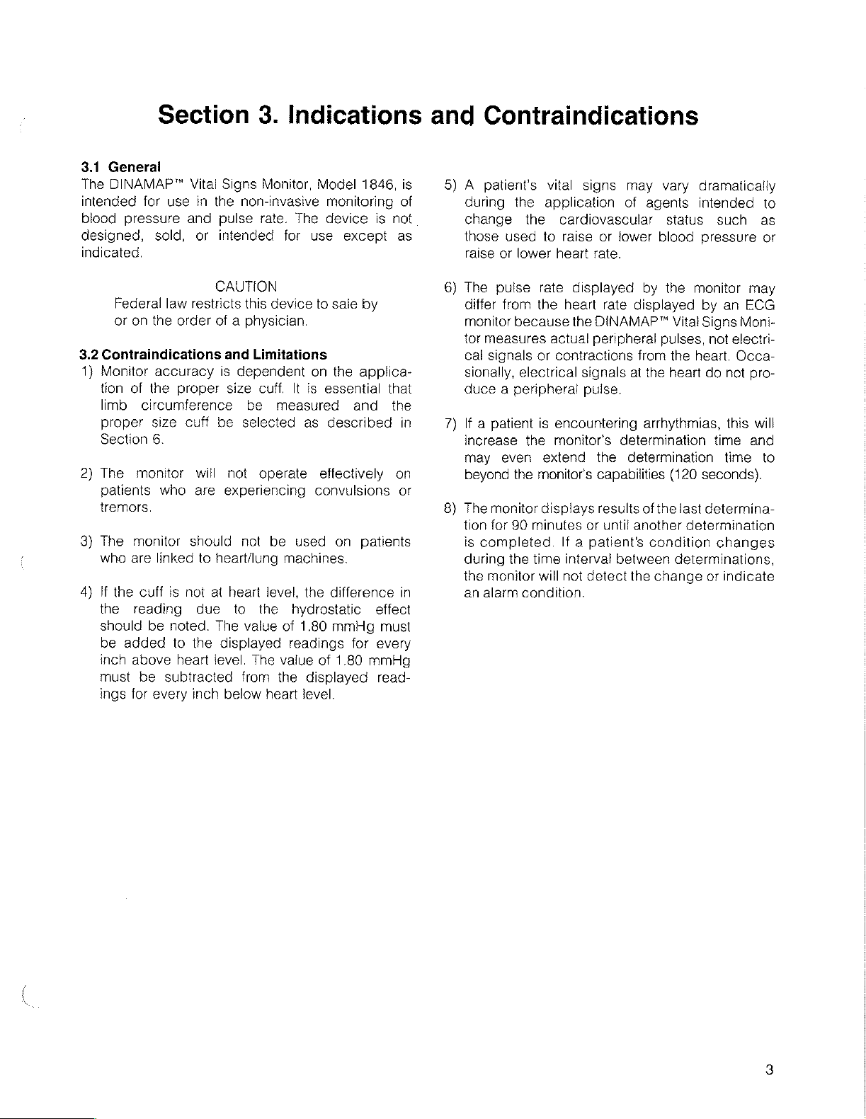
5) À patients
during
change
those
used
raise
or
vital
the
application
the
to
lower
heart
signs
may
of
cardiovascular
raise
or
lower
rate.
vary
agents
status
blood
dramatically
intenced
such
pressure
to
as
or
Federal
or
on
the
3.2
Contraindications
1)
Monitor
tion
limb
proper
Section
2)
The
patients
tremors.
3)
The
who
4)
If
the
should
be
inch
must
ings
accuracy
of
the
circumference
size
6.
monitor
who
monitor
are
linked
the
cuff
reading
be
added
above
be
for
every
CAUTION
law
restricts
order
of a
is
proper
cuff
be
will
are
should
to
heart/lung
is
not
at
due
noted.
subtracted
to
the
heart
The
displayed
level.
inch
this
device
physician.
and
Limitations
dependent
size
cuff.
It
be
measured
selected
not
operate
experiencing
not
be
machines.
heart
level,
to
the
hydrostatic
value
of
readings
The
value
from
the
below
heart
to
sale
on
the
is
essential
as
described
effectively
convulsions
used
on
the
difference
1.80
mmHg
of
1.80
displayed
level.
by
applica-
that
and
the
patients
effect
must
for
every
mmHg
read-
in
on
or
in
6)
The
pulse
differ
monitor
tor
measures
cal
signals
sionally,
rate
from
the
because
or
electrical
duce a peripheral
7)
If a patient
increase
may
beyond
8)
The
monitor
tion
for
is
completed.
during
the
monitor
an
alarm
is
the
even
the
monitor's
90
minutes
the
time
will
condition.
displayed
heart
rate
the
DINAMAP™
actual
peripheral
contractions
signals
pulse.
encountering
monitors
extend
the
capabilities
displays
results
or
until
If a patient's
interval
not
detect
by
the
monitor
displayed
Vital
pulses,
from
the
heart.
at
the
heart
arrhythmias,
determination
determination
(120
ofthe
last
another
between
the
determination
condition
determinations,
change
may
by an
Signs Moni-
not
electri-
ECG
Occa-
do
not
pro-
this
will
time
and
time
to
seconds).
determina-
changes
or
indicate
Page 10
The
DINAMAP™
processor
matically
pressure,
neonates,
technique.
easy-to-read
quency
increments
operating
and
Alarms
tolic,
values
grammed
nal
Printer
determination
trends.
*Pre-set
found
not
patient.
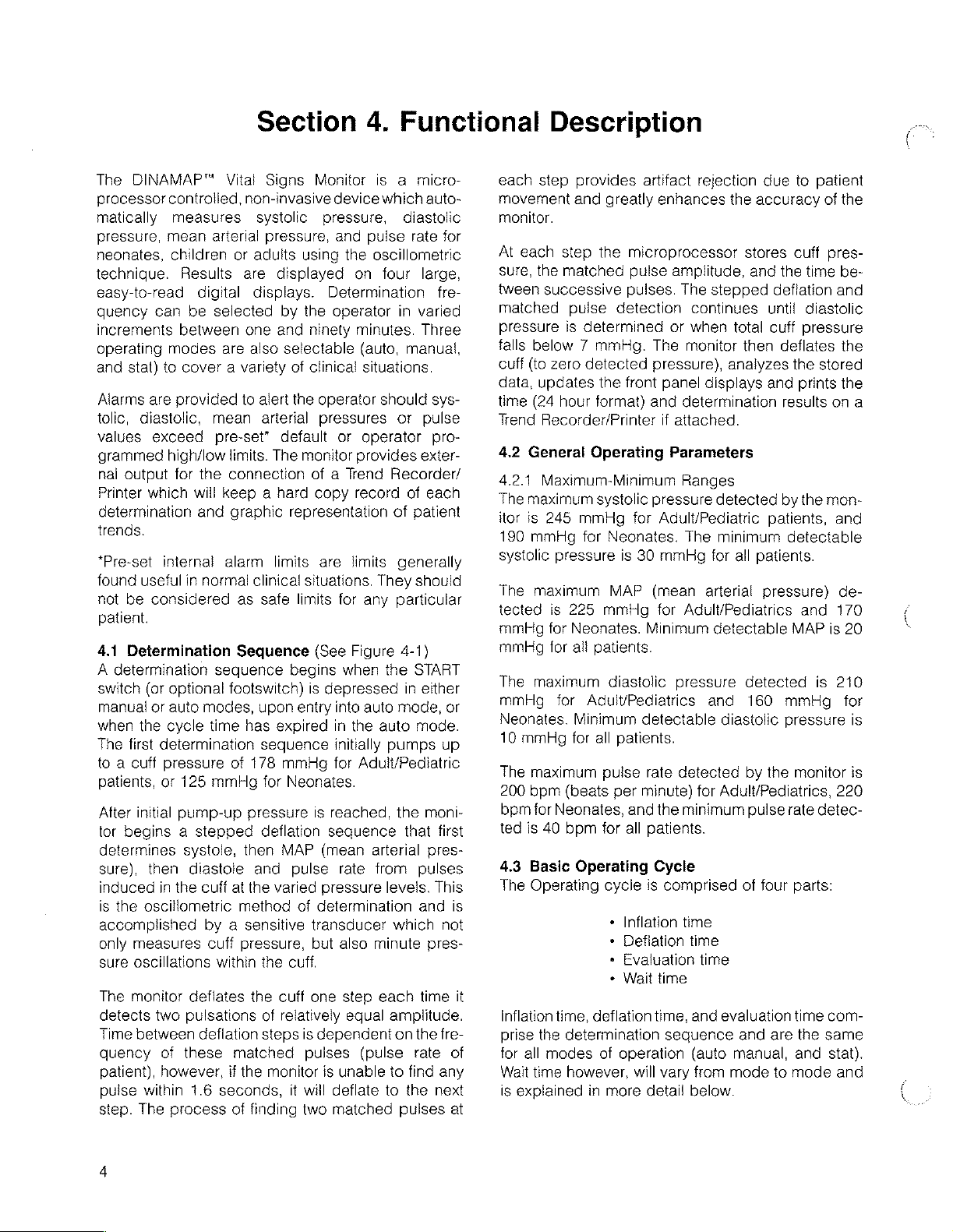
4.1
A
determination
switch
manual
when
The
to a cuff
patients,
After
tor
determines
sure),
induced
is
the
accomplished
only
sure
The
detects
Time
quency
patient),
pulse
step.
controlled,
measures
mean
children
Results
can
between
modes
stat)
to
are
provided
diastolic,
exceed
high/low
output
for
which
internal
useful
be
considered
Determination
(or
optional
or
auto
the
cycle
first
determination
pressure
or
125
initial
pump-up
begins a stepped
then
in
the
oscillometric
measures
oscillations
monitor
two
between
of
however,
within
The
process
Section
Vital
Signs
non-invasive
systolic
arterial
digital
be
selected
cover a variety
mean
pre-set”
the
will
and
in
normal
sequence
modes,
time
mmHg
systole,
diastole
cuff
by a sensitive
cuff
within
deflates
pulsations
deflation
these
1.6
seconds,
pressure,
or
adults
are
displayed
displays.
by
one and
are
also
selectable
to
alert
arterial
default
limits.
The
connection
keep a hard
graphic
alarm
limits
clinical
as
safe
Sequence
footswitch)
upon
has
expired
sequence
of
178
mmHg
for
pressure
deflation
then
MAP
and
at
the
varied
method
pressure,
the
the
cuff
of
relatively
steps
matched
if
the
monitor
of
finding
4.
Monitor
pressure,
using
Determination
the
ninety
of
clinical
the
operator
pressures
monitor
of a Trend
copy
representation
are
situations.
limits
(See
begins
is
depressed
entry
Neonates.
is
reached,
seguence
(mean
pulse
pressure
of
determination
transducer which
but
cuff.
one
is
dependent
pulses
is
it
will
two
is a micro-
device
and
pulse
the
oscillometric
on
operator
minutes.
(auto,
situations.
or
operator
provides
record
limits
They
for
any
Figure
when
into
auto
in
the
initially
for
Adult/Pediatric
arterial
rate
from
also
minute
step
equal
(pulse
unable
deflate
matched
Functional
which
auto-
diastolic
rate
for
four
large,
fre-
in
varied
Three
manual,
should
auto
each
sys-
or
pulse
pro-
exter-
Recorder/
of
each
of
patient
generally
should
particular
4-1)
the
START
in
either
mode,
or
mode.
pumps
levels.
amplitude.
on
to
to
the
moni-
that
pres-
pulses
and
pres-
time
the
rate
find
the
pulses
up
first
This
not
fre-
any
next
is
it
of
at
Description
each
step
movement
monitor.
At
each
step
sure,
the
matched
tween
successive
matched
pressure
falls
cuff
data,
time
Trend
4.2
4.2.1
The
itor
190
systolic
The
tected
mmHg
mmHg
The
mmHg
Neonates.
10
mmHg
The
200
bpm
ted
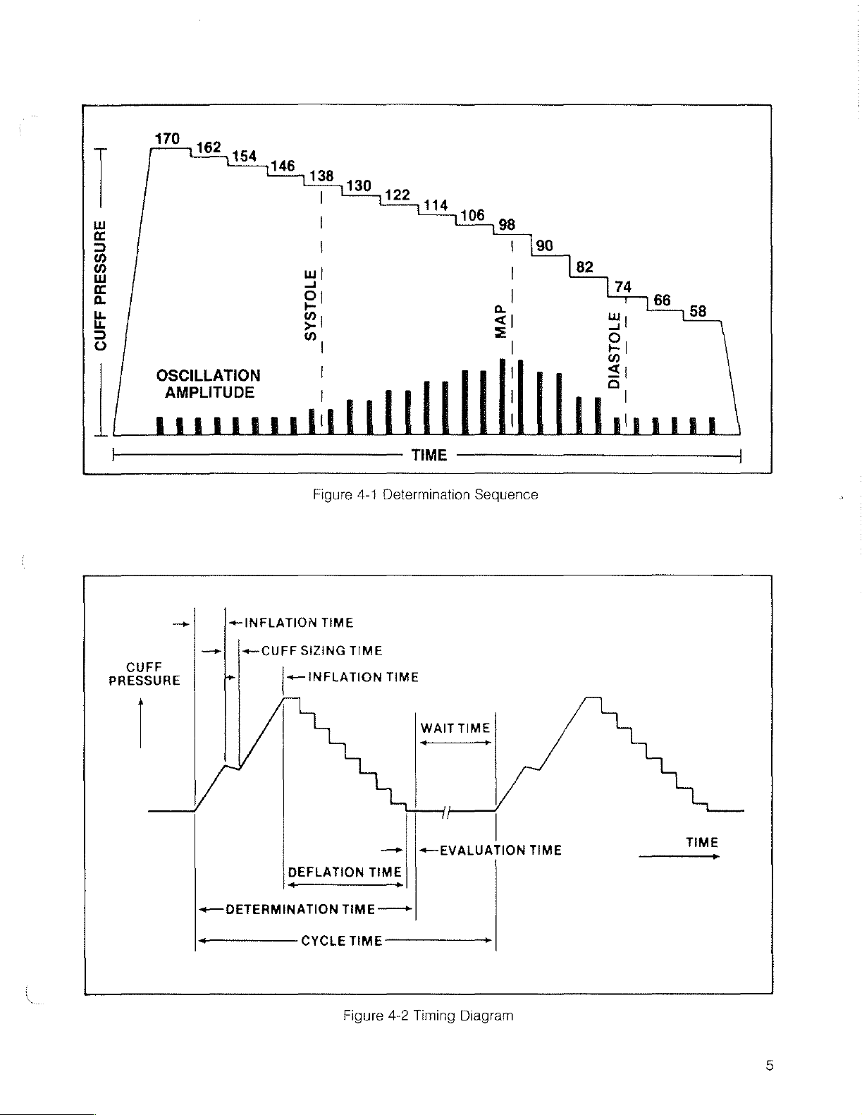
4.3
The
Inflation
prise
for
Wait
is
explained
pulse
is
below 7 mmHg.
(to
zero
updates
(24
hour
Recorder/Printer
General
Maximum-Minimum
maximum
is
245
mmHg
pressure
maximum
is
225
for
Neonates.
for
ali
maximum
for
for
maximum
bpm
(beats
for
Neonates,
is
40
bpm
Basic
Operating
time,
the
determination
all
modes
time
however,
provides
and
determined
artifact
greatly
the
enhances
microprocessor
pulse
amplitude,
pulses.
detection
or
The
The
detected
the
format)
Operating
systolic
mmHg
for
mmHg
pressure),
front
panel
and
if
Parameters
pressure
for
Adult/Pediatric
Neonates.
is
30
mmHg
MAP
(mean
for
Minimum
attached.
patients.
diastolic
pressure
Adult/Pediatrics
Minimum
all
Operating
deflation
in
detectable
patients.
pulse
rate
per
minute)
and
for
all
patients.
cycle
is
+
Inflation
«
Deflation
*
Evaluation
*
Wait time
of
operation
will
more
detail
detected
the
Cycle
comprised
time,
sequence
vary
rejection
the
accuracy
due
stores
and
the
stepped
continues
when
monitor
displays
determination
Ranges
detected
deflation
until
total
cuff
then
analyzes
and
deflates
results
by
patients,
The
minimum
for
all
arterial
Adult/Pediatrics
detectable
and
diastolic
for
Adult/Pediatrics,
minimum
time
detectable
patients.
pressure)
detected
160
mmHg
pressure
by
the
pulse
of
four
time
time
and
evaluation
and
are
(auto
manual,
from
mode
to
below.
to
patient
of
cuff
pres-
time
diastolic
pressure
the
stored
prints
on
the
mon-
and
MAP
is
is
monitor
rate
detec-
parts:
time
com-
the
same
and
stat).
mode
the
be-
and
the
the
a
and
de-
170
20
210
for
is
is
220
and
Page 11
一]
一 一
PRESSURE
SIZING
+—
INFLATION
SYSTOLE
Figure
4-1
TIME
TIME
CUFF
OSCILLATION
AMPLITUDE
トーーーーー
INFLATION
>}
[+
CUFF
CUFF
PRESSURE
|
TIME
Determination
TIME
WAIT
TIME
Sequence
+—
DETERMINATION
ーーーーーーー
DEFLATION
—_+
CYCLE
—+|
|«—
TIME
TIME 一 一
TIME 一 ーーーーーーーー
Figure
4-2
一
Timing
EVALUATION
テ
Diagram
TIME
TIME
Page 12
4.4
Operating
4.41
Manual
The
manual
eration
for
cally after
default
up
but
alarm
may
particular
8.2).
In
the
made
each
pressed.
is
pressed
update)
to
monitor
90
minutes
flashes
begins
pressure
Modes
Mode
mode
the
monitor
pressing
limits
be
changed
patient
manual
time
Wait
time
again.
at
another
is
based
(and
in
which
determination.
A
determination
pressing
deflate
cycle
tered.
determination
pressing
silence
leaving
Any
out,
cause
pre-set
operation
4.4.2
The
MANUAL
tion
detected, a second
the
the
UTES
is
pressed).
resuits
UTES
elapsed
to
the
A
determination
pressing
deflate
played
the
the
cuff,
and
leave
Alarm
indicators
the
and
extinguish
operator
momentary
or
cycling
the
monitor
default
mode
Auto
Mode
auto
mode
switch.
will
be
initiated
alarm.
Subsequent
expiration
display
(or
Pump-up
of
the
display
time
since
operator
the
the
cuff,
in
the
CYCLE
CANCEL
place
has
CANCEL
power
of
the
alarm
prior
may
of
last
will
set
CANCEL
and
is
the
normal
(ihe
mode
the
POWER
automatically
by
the
(see
Set
Alarms
mode, a single
only
when)
is
indefinite
Elapsed
the
may
CYCLE
time
90
on
the
be
cancelled
time
all
minute
switch.
the
monitor
any
operator-set
can
be
caused
an
switch.
all
patient
set
alarm
limits
NOTE
interruption
POWER
to
revert
limits
to
be
In
the
immediately.
determination
ON/OFF
to
manual
in
effect
interruption.
entered
auto
mode
determinations
time
displayed
at
any
time
when
pressure
determination.
periodically
the
last
data
cycle
time.
may
be
cancelled
switch.
begin a new
MINUTES
power-up
entered
ON
switch).
activate
operator
Procedure
determination
the
START
until
the
START
(since
MINUTES
displays
count.
results
at
This
operation
back
alarm
cancelled
alarm
condition)
This
operation
alarm
unaltered,
(blackout,
switch
mode
regardiess
by
pressing
the
first
If a patient
is
initiated
in
the
the
START
is
based
The
show
or
update,
at
This
operation
wait
display).
mode
of
automati-
Pre-set
at
power-
to
suit
Section
switch
switch
the
last
display
zero
and
Pump
of
the
any
time
into
the
limits
unal-
(after
indicators
brown-
etc.)
with
of
the
AUTO/
determina-
alarm
to
verify
will
occur
CYCLE
MIN-
switch
on
CYCLE
MIN-
“flash”
then
return
any
time
time
(as
Any
opera-
op-
any
is
is
data
up
the
up
last
by
will
wait
a
by
will
will
the
the
is
at
the
the
by
will
dis-
tor
set
alarm
limits
can
be
cancelled
an
alarm
condition)
This
operation
alarm
indicators,
played
any
4.4.3
The
ing
tor
minute
tion
onds
will
vious
The
above
tolic
125
in
tions.
down,
is
begins).
“flash”
window
When
determined,
these
play
cease
in
the
operator
Stat
stat
the
will
programmed
Mode
mode
STAT
MODE
initiate a series
period. A determination
of
the
five
for
example)
be
displayed
mode
(manual
series
is
mmHg
the
begins
previous
stored,
for
stat
mode
in
the
stat
systolic
determined
The
the
value
to
indicate
MAP
pulse,
the
updated
windows.
to
“flash.”
determination
or
the
operator
Patient
mode,
alarm
attached)
tions
ute
switch,
mode
(manual
4.4.4
These
tains
patients
default
internal
alarm
however,
will
and
or
display
stat
mode
the
of
operation
or
Neonatal
are
two
sets
and
alarm
algorithms
be
monitor
auto).
switched
the
limits
will
be
unaltered.
(after a determination
by
pressing
will
silence
and
begin a new
CYCLE
MINUTES
alarm
may
be
entered
switch.
minute
will
before
with
systolic
to
178
Neonates.
to
allow
mode,
pressure
(usually a few
monitor
in
the
that
and
monitor
values
The
systolic
The
unless
has
limits
cannot
the
noted
will
not
of
values.
period
prior
or
Adult/Pediatric
of
standards:
other
as
are
In
the
of
determinations
period
cycle
or
mmHg
(at 4 minutes,
to
the
monitor
auto).
cuff
inflation
value,
for
Artifact
for
accelerated
as
the
is
displayed
seconds
will
sound a short
SYSTOLIC
this
is
diastolic
sounds a short
will
appear
value
monitor
will
the 5 minute
pressed
be
occurrence
on a Trend
inhibit
the
At
the
or
after
will
automatically
to
initiation
automatically.
One
for
Neonatal
well
as
pump-up
altered
Alarm
indicators
has
the
CANCEL
extinguish
wait
display),
limits
at
any
stat
all
period
and
unaltered.
time
by
mode,
the
for a five
begun
conclusion
before
and
reverts
to
to a pressure
or
if
no
previous
Adult/Pediatrics
rejection
is
determina-
monitor
begins
the
after
instant
stepdown
tone
pressure
updated
pressure
information.
values
tone
in
the
respective
will
be
updated
then
begin
period
the
accessed
has
CANCEL
of
an
out-of-limits
during
Recorder/Printer
series
of
determina-
expiration
pressing
of
the 5 min-
the
CANCEL
revert
of
the
stat
Monitoring
The
monitor
for
Adult/Pediatric
patients.
pressure
in
the
Neonatal
caused
switch.
patient
(as
dis-
leave
press-
moni-
expira-
55
sec-
results
the
pre-
sys-
and
relaxed
step-
that
it
and
display
are
and
dis-
and
another
expired
switch.
stat
(if
to
the
mode
con-
Pre-set
and
mode.
a
Page 13

The
monitor
mode
by
sensing
will
intervention.
44.5
Systolic
In
any
operating
pressure
the
unit
exceed
will:
Begin
Detect
Stop
Re-inflate
fons
pressure
§.
Resume
The
monitor
pressure
will
through
automatically
cuff
size
Search
mode,
the
monitors
normal
the
deflation
absence
deflation
to a higher
(250mmHg
normal
deflation
continue
subsequent
switch
and
should a patient’s systolic
into
requires
pump-up
the
proper
no
operator
pressure,
sequence
of a systolic
(than
re-inflate
value
initial)
pump-up
maximum)
sequence
to
use a higher
determinations
pump-up
until
such
time
as
the
unit
will
then
lower
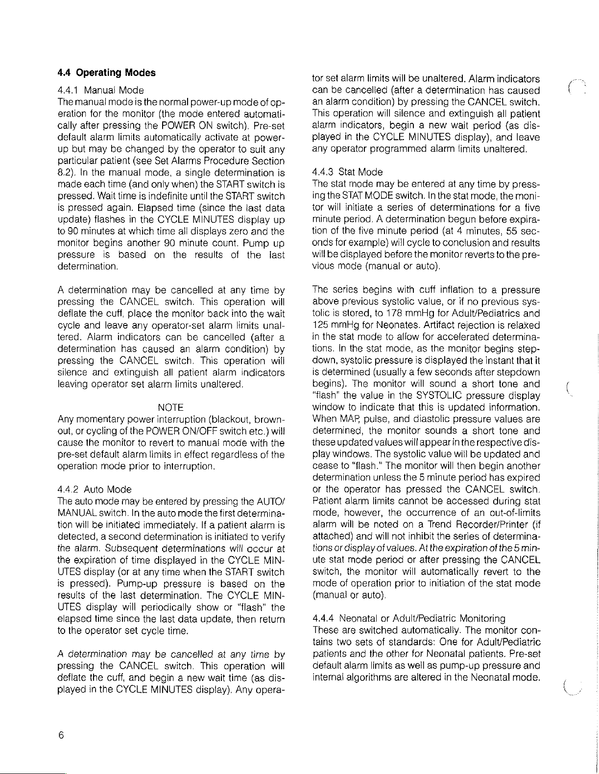
4.5
Undetermined
Pressures
Under
play only
diastolic
tolic/diastolic
ations
Because
systolic
only
played.
monitor
tions
certain
MAP
pressures.
waveform
as
shown
of
the
and
diastolic
MAP
can
If
this
will
attempt
after a 15
patient's
systolic
pump-up
Systolic
pressure
and
circumstances,
and
not
display
If
the
patient
has
very
below.
relatively
be
accurately
should
one
second
small
pressure
occur
when
or
more
delay.
pressure
accordingly.
Diastolic
the
monitor
values
for
is
in
shock,
low
amplitude
difference
in a shock
determined
in
auto
additional
fails.
The
may
dis-
systolic
the
and
sys-
fluctu-
between
situation,
and
dis-
mode,
determina-
the
Normal
Pressure
Pressure
in
Shock
Situation
Adult
SYS
MAP
DIA
SYS
MAP
DIA
120
86
70
30
23
20
Figure
Neonate
(SYS
(MAP
(DIA
(SYS
(MAP
(DIA
4-3
80)
47)
30)
20}
14)
10)
Low
-~
Amplitude
Waveform
E
2
Diagram
ーー
SYS/DIA
Difference
50mmHg
SYS/DIA
Difference
>
10mmHg
Page 14

Section
5.1
Operating
Section 5 contains a physical
5-1
are
general,
tions
refer
5.1.1
Physical
Requirements
to
Sections
physical
characteristics
13
through
Characteristics/Operating
description
16.
5.
Physical
of
the
monitor's
and
operating
Requirements
Description
controls,
requirements.
indicators,
For
the
complete
and
connectors.
list
of
Covered
technical
in
Table
specifica-
MONITOR
Height
Width
Depth
WEIGHT
POWER
REQUIREMENTS
Input
Input
FUSE
REQUIREMENTS
PRINTER
OPERATING
STORAGE
HUMIDITY
ALTITUDE
DIMENSIONS
Power
Voltage
(Domestic)
(International)
FUSES
TEMPERATURE
TEMPERATURE
RANGE
RANGE
4.85
inches
10.75
inches
10.75
inches
18
lbs.
max
19
lbs.
max
0.8
Amps
max.@100,
0.5
Amps
max.@220,
120
VAC/60
§7-63
100
VAC/50
47-63
220
VAC/50
47-63
240
VAC/50
47-63
120
VAC/60
SLO-BLO @ 250
100
VAC/50
SLO-BLO @ 250
220
VAC/50
SLO-BLO @ 250
240
VAC/50
SLO-BLO @ 250
100/120
220/240
+50°F
—
0
to
—
to + 104°F
29°F
95%
1000
VAC,
VAC,
to + 140°F
non-condensing
to + 15,000
(60
Hz
Unit)
(50
Hz
Unit)
Hz
(nom.),
Hz
Hz
(nom.),
Hz
Hz
(nom.),
Hz
Hz
(nom.),
Hz
Hz-1
each, 1 1/2A,
Hz-1
each, 1 1/2A,
Hz-2
each,
Hz-2
each,
3A
SLO-BLO @ 250V
3.15A
SLO-BLO
(+
(—
feet
120
240
104-132
88-112
194-246
212-268
V
V
0.8A,
V
0.8A,
V.
10°C
34°C
VAC
VAC
VAC/
VAC/
VAC/
VAC/
SAG,
3AG,
FST,
FST
@
250V
to + 40°C)
to
+60°C)
5.2
Controls
DINAMAP™
Table
5-2.
Vital
The
and
Signs
rear
Table 5 - 1 General
Indicators
Monitor.
panel
Controls
The
controls
and
front
and
indicators
Characteristics/Operating
indicators
pane!
controls
are
are
and
shown
situated
indicators
in
Figure
Requirements
on
both
the front
are
shown
5-2
and
in
figure
defined
and
in
rear
5-1
Table
panels
and
5-3.
of
the
defined
in
Page 15

κ
SYSTOLICÍ
mmHg
PULSE
bpm
ALESIGNS
NONITORH1646
CYCLE
TUE)
SET
m
DIASTOLIG
a.
Bi
È |
Reference
1
17
MAP
Table
Placard
mmHg
Figure
5-2
Front
5-1
Front
Panel
This
3-digit red
In
addition
+
Flashes
«
Shows
pressed
«
Displays
15
Panel
Controls
this
cuff
hours
MAP
14
Controls
and
LED
display
display:
pressure
contained
alarm
limits
13
and
Indicators
Indicators
Function
shows
during
in
the
(see
deflation
24
12
Defined
mean
arterial
time
hour
clock
reference
pressure.
when
4,
SELECT).
11
TIME
OF
10
DAY
is
de-
CUFF
kPa
SELECT
This
illuminated
kPa
indicators
and
French
This
momentary
played.
SYSTOLIC,
to
Pressing
allow
high
third
limits
return
ond
matically
Pressing
display
the
and
and
respectively
the
time
indicator
will
only
language
pushbutton
the
and
allow
the
high
and
the
switch a second
HIGH
LIMIT
low
MAP
alarm
fourth
time
in
values
limit
returns
for
of
the
each
to
signifies
light
units
switch
the
HIGH
low
and
LOW
limits
will
allow
the
same
last
determination
of
these
the
previous
that a determination
if
internal
only).
switch
the
first
LIMIT
systolic
alarm
time
will
LIMIT
in
the
setting
manner.
operations,
displays.
kPa
switch
selects
time
will
and
LOW
limits
blank
switches
MAP
display.
pulse
rate
Pressing
to
aii
at
is
the
alarm
blank
LIMIT
in
the
all
displays,
to
be
and
the
displays.
which
is
in
progress.
set
(German,
limits
to
all
displays,
switches
SYSTOLIC
used
Pressing
diastolic
switch a fifth
There
time
except
to
the
high
the
monitor
to
display
is a 10
British
be
dis-
except
be
used
display.
MAP
and
the
switch
and
low
time
will
sec-
auto-
a
Page 16

Table
5-2
Front
Panel
Controls
and
Indicators
Defined
(Cont'd)
5
6
7
AUTO/MANUAL
START
STAT
MODE
This
momentary
and
indicates
will
change
LED.
Manual
Asingle
is
determination
pressed.
Subsequent
the
CYCLE
initlated
The
at
This
or
wait
ual
in
by
cycle
the
beginning
momentary
auto
mode.
time;
mode,
auto
mode,
timer
if
begin a new
This
momentary
the
stat
mode
manual
minute
however,
or
period.
the
Recorder/
tions
or
display
return
to
the
was
auto,
cycle
mode.
state.
ing
was
GEL
If
that
Exit
from
CANCEL.
initiated.
is
pressed.
pushbutton
the
mode
the
operating
mode
is
entered
is
In
auto
mode
determinations
MINUTES
pressing
is
started
of
each
display
the
pushbutton
The
START
pressed
determinations
during
pressing
the
cycle.
pushbutton
of
operation.
auto
mode
and
Patient
alarms
occurrence
Printer
of
mode
time
mode
the
This
If
that
(if
attached)
values.
it
was
will
was
stat
mode
will
return
mode
switch
of
operation
mode
when
made
each
one
occur
(reference
START
when
auto
automatic
switch
switch
any
other
are
initiated
START
switch
Stat
will
perform
cannot
of
an
out-of-limits
and
Atthe
end
in
before
begin
at
manual,
may
the
was
auto,
with
adjacent
for
the
as
indicated
power
time
the
determination
at
the
end
12).
switch
(or
mode
determination.
will
initiate a determination
will
initiate a determination
time,
only
switch
mode
and
will
yellow
may
LED
monitor.
by
is
first
applied
START
is
of
the
Determinations
footswitch)
is
first
entered
there
will
by
pressing
initiate a determination
LED
be
entered
continuous
be
accessed
alarm
will
will
not
inhibit
the
of
the 5 minute
stat
mode
was
the
end
of
the
last
the
monitor
be
accomplished
monitor
the
to
the
cycle
will
mode
time
return
indicators
Pressing
the
associated
switch
initiated
cycle
controls
this
to
the
monitor.
(or
footswitch)
immediately.
time
shown
may
during
and
wait
is
restarted
in
only
be
no
effect.
the
START
selects
at
and
any
indicates
time
determinations
during
be
series
period,
initiated.
STAT
noted
of
the
If
on a Trend
determina-
monitor
that
determination
to
the
wait
at
it
will
anytime
was
begin
by
in
before
when CAN-
switch
green
in
also
be
time.
manual
during
In
man-
switch.
and
from
for a 5
made,
will
mode
in
stat
time
press-
stat
10
10
11
CANCEL
SYSTOLIC
DIASTOLIC
POWER
ON
OFF
mmHg
mmHg
This
momentary
this
switch
alarms
exit
the
CANCEL
ted.
Visual
displays
This
3-digit
In
addition
+
Shows
pressed
«
Displays
This
3-digit
In
addition
e
Displays
This
pushbutton
will
except
certain
calibrate
is
pressed
and
will
maintain
red
this
minutes
systolic
red
this
diastolic
pushbutton
switch
performs
terminate a determination,
system
mode.
during
audible
the
LED
display
if
CANCEL
stepping
alarms
last
shows
alarms
(see
is
time,
may
be
cancelled
determined
systolic
Table
pressed
the
values.
display:
contained
alarm
LED
display
display:
alarm
latching
in
limits
shows
limits
switch
the
24
(see
reference
the
(see
reference
controls
hr.
diastolic
the
several
cancel
functions.
all
10-1),
during
visual
exit
determination
during
pressure.
clock
when
4,
SELECT).
pressure.
4,
SELECT).
AC
power
and
stat
mode,
inflation
will
wait
time
TIME
OF DAY
to
the
monitor.
Pressing
audible
and
time,
or
be
abor-
and
the
if
is
Page 17

Table
5-2
Front
Panel
Controls
and
Indicators
Defined
(Cont'd)
12
13
14
(CYCLE)
SET
HIGH
LIMIT
MINUTES
This
2-digit,
matic
mode.
in
auto
or
manual
flashed
the
using
played
data
Pressing
ation.
cuff
This
auto
and
calibrate
pressing
manual
This
selected
the
in
the
display
the
SET
periodically
update.
START
Pressing
and
begin a new
momentary
mode.
90
minutes.
mode
CANCEL.
mode.
momentary
by
display
overlapping
played
limit
at
alarm
the
red
LED
display
The
display
mode,
CYCLE
indicates
switch.
to
at
any
CANCEL
pushbutton
The
MINUTES
Pressing
(see
pushbutton
the
SELECT
to
step
through
the
low
time
the
setting.
is
blanked
elapsed
MINUTES
the
cycle
The
elapsed
indicate
time
cycle.
increments
SET,
Section
This
will
switch.
the
limit
will
HIGH
shows
the
cycle
time
in
minutes
when
in
time
display.
time
of 3 minutes,
time
the
amount
will
begin a new
manual
(since
When
of
the
of
the
auto
mode
This
current
time
elapsed
cycle
or
last
during a determination
switch
zero
switch
not
LIMIT
as
power
9).
Calibrate
the
displays
If
pushed
entire
range
be
displayed).
switch
increments
are
1,
2,3, 4,5,
is
applied,
displays
the
and
held,
of
high
is
released
the
mode
and
current
the
limit
Whatever
stat
data
is
may
be
cycle
and
new
will
MINUTES
10, 15,
will
place
can
return
high
switch
settings
will
be
when
in
auto-
modes.
When
update)
first
entered,
changed
is
briefly
since
the
determin-
deflate
when
20, 30, 45,
the
unit
be
exited
the
unit
alarm
will
cause
(settings
setting
the
is
new
is
by
dis-
last
the
in
60
in
by
to
limit
dis-
high
15
16
17
LOW
LIMIT
ALARMS
PULSE
ON/OFF
bpm
This
momentary
selected
the
by
display
to
overlapping
play
at
the
time
alarm
setting.
This
momentary
of
the
audio
when
an
alarm
green
LED
will
wil!
be
lit
and
inhibited
This
In
+
Displays
(refer
+
Displays
and
3-digit
addition
to
Section
this
the
pulse
pushbutton
the
SELECT
step
the
high
the
pushbutton
alarm.
condition
flash
when
the
yellow
red
LED
display:
800
rate
switch.
through
limit
will
LOW
LIMIT
in
the
is
on
and
an
alarm
LED
display
series
11).
alarm
switch
If
pushed
the
entire
not
be
switch
switch
with
ON
state,
detected,
off.
in
the
condition
will
flash
shows
alarm
codes
limits
(see
displays
range
and
of
the
heid,
low
displayed).
is
released,
LED
indicators
the
green
the
audio
OFF
state,
is
detected,
on
and
off.
the
pulse
rate.
during
reference
current
the
limit
Whatever
will
be
(top)
LED
alarm
will
the
yellow
the
audio
certain
4,
SELECT).
low
alarm
switch
will
settings
setting
the
new
controls
will
be
sound
(bottom)
alarm
alarm
conditions
limit
cause
(settings
is
dis-
low
limit
the
state
lit
and
and
the
LED
will
be
11
Page 18

CRITIKON
EO
DST
EE
E
INC
<<:
Reference
1
Placard
TIME
OF DAY
PRINTER
DATA
INTERFACE
ALARM
Table
VOL.
Figure
5-3
Rear
This
for
tion
displays.
SYSTOLIC
cates
replacement.
Connector
Connector
computer.
This
safe).
wise
alarm,
7
5-2
Rear
Panei
Panel
Controls
3-position
procedure).
displays
potentiometer
Turning
will
Hours
display.
that
the
port
port
decrease
it
can
the
the
only
Controls
and
switch
Moving
contents
are
If
the
clock
for
connection
for
connection
adjusts
control
the
attenuate
and
Indicators
Function
displays
this
switch
of
the
displayed
time
of
baitery
on
the
clockwise
volume.
it.
6
indicators
Defined
and
sets
the
to
the
24
hour
clock
in
the
day
is
flashed
the
CPU
of
Trend
Recorder/Printer
of
analog
volume
wiil
This
of
increase
control
time
of
momentary
in
the
MAP
display;
ata 1 Hertz
board
strip
chart
the
audio
the
cannot
day.
(See
TIME
MAP
is
low
recorder
alarms
volume,
silence
Section
OF
DAY
posi-
and
SYSTOLIC
minutes
rate,
and
cable.
counterclock-
in
this
in
need
or
external
(except
the
audio
indi-
fail-
8.6
the
of
12
SWITCH
CUFF
TONE
CONNECTOR
This
3-position
When a valid
generated
three
nates
Screw
at
lower
these
type
switch
front
panel
the
rear
frequency
audio
tones.
connectors
controls
switch
panel
speaker.
audio
for
connection
the
entry
tones
volume
is
are
of
made, a single,
When
an
generated.
of
pneumatic
the
audible
invalid
The
short
entry
OFF
position
(cuff)
hose.
switch
is
tones.
audio
tone
atternpted,
is
elimi-
Page 19

Table
5-3
Rear
Panel
Controls
and
Indicators
Defined
(Cont'd)
PRINTER
LINE
POWER
Power
Cord
Connector
Fuse
Fuse
Printer
fuse
Section
Monitor
AC
power
(functional
15
for
rating.)
fuse,
(See
cord
when
Section
connector
Trend
15
for
with
Recorder/Printer
rating).
retaining
clip.
is
attached).
(See
13
|
]
Page 20

6.1
Initial
Section 6 contains
instructions,
tions,
6.1.1
The
items
inspect
representative,
1-800-237-7517
instrument
1-800-237-5591
1 - Vital
1 - Operation
1 -
Cuff
1 -
Pneumatic
Adult/Pediatric)
1-
Pneumatic
Neonatal)
1-Set
1 -
Calibration
1 - Power
6.1.2
With
1.
Check
number
and
receptacle
Set
electrical
as well as
Unpacking
monitors
listed
each
is
it
is
advisable
erials
(box,inserts)
was
shipped
store
the
Center
for
Signs
(Standard
Neonatal
Cord
Electrical
Monitor
the
plate
make
Up
cuff
the
shipping
in
Table
item.
If
or
(1-800-282-7533
damaged,
(1-800-282-9151
unit
repair.
Monitor
Monitor
Manual
Hose
Hose
Cuffs
Kit
and
Off:
voltage
attached
sure
to
be
Section
preparation
and
pneumatic
size
and
Monitor
carton
6-1
below.
an
item
is
Critikon,
to
in
or
Adult)
with
with
Hose
it
matches
used.
contact
NOTE
keep
in
which
the
event
return
Checklist
Model
Connectors
Luer
(4
per
set)
Table
Connections
rating
to
inc.
6-1
and
placement
should
Account
missing
Customer
in
Florida).
Field
in
Florida).
the
original
your
that
you
it
to a Service
1846
Connector
(5
per
set - Dec
stamped
the
rear
the
line
6.
Monitor
initial
set-up
hose
connec-
instructions.
contain
for
call
your
sales
Service
If
Service
mat-
monitor
wish
to
(12
ft.
-
Block
(8
1984)
on
the
serial
of
the
monitor
voltage
of
the
and
at
the
at
ft.
the
-
Installation
panel.
age
.
Connect
at
connection;
either
monitor
TIGHTEN.
tightening
.
Measure
proper
cuff
.
.
.
Plug
the
receptacie.
the
dual-pneumatic
the
rear
panel.
either
port.
Thread
ports
The
the
the
limb
size
cuff
or
cuff
package.
Cuff
Type
Neonate
Neonate
Neonate
Neonate
Neonate
Infant
Child
Smail
#1
#2
#3
#4
#5*
Adult
Adult
Large
Adult
Thigh
*
available
Table
6-2
Cuff-to-
Connect
connectors
the
cuff
onto
OVERTIGHTEN.
Squeeze
Place
6-1.
be
so
determinations.
all
the
Observe
placed
tight
as
the
cuff
the
over
to
EXCESSIVE
CONGESTION
THE
LIMB.
other
until
pneumatic
connector.
on
end
There
hose
the
hose
finger-tight
of
the
according
December
Hose
to
the
the
hose
air
from
the
the
patient
mark
on
the
artery.
prevent
venous
NOTE
TIGHTNESS
AND
DISCOLORATION
into
an
appropriate
hoses
to
is
no
preferred
may
be
connected
connectors
DO
NOT
seal
is
NOT
patient
to
the
Use
and
size
Hose
330-020
330-020
330-020
330-020
330-020
330-017
330-017
330-017
330-017
330-017
330-017
1984
Compatibility
hoses.
the
Thread
connectors.
cuff.
as
shown
inside
of
Be
sure
the
return
WILL
CAUSE
the
monitor
order
onto
OVER-
made
select
marked
No.
the cuff
DO
in
Figure
the
cuff
cuff
between
OF
volt-
the
by
the
on
NOT
is
not
of
to
to
Connect
monitor
14
the
detachable
and
engage
10-foot
the
cord
power
lock
cord
on
the
to
the
rear
“Note:
Do
ity
being
not
used
place
the
for
cuff
on
an
intravenous
extrem-
infusion.
Page 21

一 一
一
一
一
CRECOMMENDEDCUFFREPLACEMENT
)ーーーーーーーーーーー」
u
8.
If
another
is
it
becomes
used.
To
obtain
ity
and
ADULT/PEDIATRIC
limb,
accurate
cuff
necessary
make
motion
to
sure
the
NOTE
determinations,
must
be
-一
Figure
change
appropriate
minimized.
the
extrem-
一
cuff
size
6-1
to
cuff
Cuff
Placement
9.
Before
operating
NEONATE
powering
precautions
up
the
monitor,
listed
in
Section
read/review
7.
all
15
Page 22

7.1
Operating
Although
been
designed
in
medical
observe
and
reliable
1)
Read
material
2)
Read
labels
3)
Place
Section
Precautions
the
DINAMAP™
to
provide
environments, a responsible
the
following
operation
and
have a thorough
presented
and
observe
affixed
the
to
monitor
the
Vital
safe
and
precautions
of
this
unit.
understanding
in
this
manual.
all
the
caution
unit.
on a rigid,
Signs
to
secure
7.
Monitor
reliable
operator
ensure
and
surface.
Operating
has
operation
will
the
safe
of
the
warning
4)
5)
6)
7)
8) A momentary
Precautions
Arrange
carefully
Allow
of
Do
Do
able
monitor
default
the
so
they
for
heat
the
chassis
not
place
not
use
the
anesthetics.
to
revert
alarm
power
do
dissipation
is
unobstructed.
fluids
monitor
power
to
limits
cord
and
pneumatic
not
constitute a hazard.
by
ensuring
on
the
monitor.
in
the
presence
interruption
manual
in
effect.
will
mode
that
of
cause
with
hoses
the
rear
flamm-
the
preset
16
Page 23

8.1
Power-up
Push
serve
eights
in
that
in all
1,
tors as a check
audio
alarm
ation.
.
Setthe
itor
and
Set
to
on
the
ALARM
the
while
SWITCH
monitor
Set
the
audio
panel
to
itor
will
generate
dition
and
ALARM
tient
and
yellow
866,
Table
Check
.
OF
Set
limits
from
8.2
The
each
Neonatal
with
LED
or
10-1).
DAY
the
if
the
Set
Alarm
Adult
time
Neonatal
877
and/or
it
limits
inspecting
are
as
follows:
SYSTOLIC
SYSTOLIC
Procedure
the
locking
the
digital
for
is
also
VOL.
desired
adjusting
TONE
to
the
desired
ALARM
the
desired
an
the
green
OFF
the
audio
excess
indicator
alarm
set
switch
systolic,
preset
is
desired
on
MAP
values.
Limits
preset
power
default
is
are
desired
cuff
or
changing
high
limit = 240
low
limit
Section
POWER
monitor
displays
the
warbled
level
mode.
audio
time
cannot
the
the
Procedure
first
and
=
operation
control
by
the
switch
position.
ON/OFF
In
alarm
LED
alarm
alarm
will
flash.
be
time
rear
pulse,
that
these
alarm
applied
make
hose
limits.
Adult
O
momentarily
and
as a check
on
turning
control.
indicator
of
of
mmHg
mmHg
8.
ON
switch
flashes
of
all
the
rear
the
on
the
switch
ALARM
is
audio
day
and
These
ON,
for
any
will
inhibited
conditions
Any
800,
disabled
using
the
unit.
diastolic
limits
be
limits
are
to
the
one
determination
attached
default
240
Operating
and
ob-
displays
all
indica-
LEDs.
The
for
its
oper-
of
the
mon-
monitor
rear
on
alarm
monitor.
Neonate
0
off
of
the
the
front
the
mon-
con-
flash.
for
all
pa-
and
the
811,
822,
(See
`
the
TIME
alarm
changed
in
effect
prior
limits
mmHg
mmHg
In
if
to
the
If it
is
desired
lowing
1.
steps:
Momentarily
SYSTOLIC
its.
All
SYSTOLIC
vaiue
.
Momentarily
current
LIMIT
the
high
LIMIT switch
Momentarily
piay
the
play.
monitor
range
desired
Momentarily
the
MAP
All
other
display
ous
determination
Momentarily
current
hold
HIGH
ment
lease
setting.
.
Momentarily
play
Press
the
monitor
range
the
desired
Monitor
to
change
press
display
other
displays
display
of
the
previous
press
systolic high
to
cause
alarm
range
at
press
current
Press
and
to
increment
settings.
setting.
press
display
displays
will
show
press
high
limit
LIMIT
through
the
the
and
settings.
the
HIGH
press
current
hold
to
setting.
these
SELECT
to
show
will
will
show
determination).
HIGH
limit.
the
monitor
settings.
the
desired
the
LOW
low
limit
hold
LOW
through
Release
the
to
show
will
zero
if
the
SELECT
be
(or
one
HIGH
in
the
MAP
to
cause
high
alarm
LIMIT
the
LOW
low
limit
the
LOW
increment
Release
the
fimits,
the
systolic
be
blanked
zero
LIMIT
Press
to
increment
Release
setting.
LIMIT
in
the
LIMIT
LOW
switch
the
MAP
blanked
the
MAP
was
performed).
LIMIT
display.
the
monitor
range
switch
LIMIT
in
the
LIMIT
through
LOW
perform
to
enable
alarm
(or
the
to
display
and
hold
the
switch
SYSTOLIC
to
cause
the
low
LIMIT
switch
to
alarm
and
the
of
the
to
display
Press
settings.
at
the
switch
MAP
switch
the
LiMIT
to
low
switch
the
fol-
the
lim-
and
the
systolic
the
HIGH
through
HIGH
to
dis-
dis-
the
alarm
at
enabie
limits.
MAP
previ-
the
and
to
incre-
Re-
desired
to
dis-
display.
cause
alarm
at
MAP
high
MAP
low
PULSE
PULSE
high
fow
DIASTOLIC
DIASTOLIC
Table
limit
limit
limit
fimt
high
low
8-1
=
=
=
=
limit = 130
limit
=
Preset
140
mmHg
50
mmHg
220
bpm
40
bpm
mmHg
0
mmHg
Default
Alarm
100
mmHg
30
mmHg
220
bpm
40
bpm
130
0
Limits
mmHg
mmHg
.
Momentarily
the
PULSE
its.
All
other
pulse
display
previous
Momentarily
current
press
the
display
displays
will
show
determination
press
high
limit
in
to
show
HIGH
the
SELECT
the
will
be
zero
(or
if
one
LIMIT
PULSE
switch
pulse
blanked
the
was
performed).
to
display.
to
enable
alarm
and
pulse
display
lim-
the
of
the
the
Press
17
Page 24

and
crement
Release
setting.
Momentarily
play
Press
the
range
the
10.
Momentarily
DIASTOLIC
limits.
DIASTOLIC
stolic
Momentarily
11.
current
LIMIT
the
LIMIT
Momentarily
12.
play
play.
monitor
range
desired
Momentarily
13.
switch
if
no
while
return
8.3
Manual
1.
Press
hold
HIGH
through
the
the
current
and
hold
monitor
settings.
desired
All
other
value
diastolic
to
cause
high
alarm
switch
the
current
Press and
to
settings.
setting.
to
return
switch
setting
to
the
Mode
START
LIMIT
the
HIGH
LIMIT
press
the
low
the
LOW
to
increment
Release
setting.
press
display
to
displays
display
of
the
previous
press
high
the
monitor
range
at
the
desired
press
the
low
hold
increment
Release
press
the
is
pressed
limits,
the
normal
to
begin
to
cause
high
alarm
switch
LOW
LIMIT
limit
in
the
LIMIT
through
the
LOW
SELECT
show
will
be
will
show
determination).
HIGH
LIMIT
limit.
Press
to
settings.
setting.
LOW
limit
in
the
LOW
through
the
LOW
the
SELECT
display
to
within a 10
monitor
display.
each
determination.
the
monitor
range
at
tne
switch
PULSE
switch
the
LIMIT
to
enable
the
diastolic
blanked
zero
(or
to
and
increment
Release
LIMIT
switch
DIASTOLIC
LIMIT
to
the
LIMIT
or
normal
second
will
automatically
to
in-
settings,
desired
to
dis-
display.
to
cause
low
alarm
switch
the
alarm
and
the
the
dia-
display
hold
the
HIGH
through
the
HIGH
to
dis-
dis-
cause
low
the
alarm
switch
CANCEL
operation.
period
at
at
then
release
show
the
the
last
ated
manualiy
by
pressing
new
wait
.
Press
CANCEL
flate
cuff,
alarm
indicators.
8.5
Stat
Mode
i.
Press
STAT
tinual
determinations.
the cuff
Patient
mode,
alarm
will
attached)
nations
tered
from
During
exceeded,
be
noted
and
the
ute
period
.
After 5 minutes,
is
pressed,
operating
new
wait
the
amount
data
of
update. A determination
at
any
the
START
cycle,
to
or
to
cancel
MODE
is
deflated
alarms
however,
or
cannot
the
be
noted
and
will
display
manual
stat
mode,
the
alarms
on a Trend
determinations
is
completed.
or
the
monitor
mode.
cycle
If
will
initiate a determination
entering
8.6
Setting
1.
Momentarily
the
and
hour
rear
the
clock.
auto
from
Time
push
panel
to
minutes
of
display
switch.
The display
time
which
has
expired
may
time
during
switch.
abort a determination
excess
to
start
a 5
After
to
allow
be
accessed
occurence
on a Trend
not
inhibit
of
values.
or
auto
mode
if
any
patient
will
not
Recorder/
will
continue
whenever
will
the
previous
be
started.
the
This
will
time
and
minute
each
period
determination,
for
venous
during
of
an
Recorder/Printer
the
series
Stat
mode
during
alarm
be
generated
Printer
until
the
CANCEL
return
to
the
mode
The
monitor
immediately
stat
mode.
Day
up
the
TIME
OF
DAY
the
hours
(MAP
(SYSTOLIC
display)
will
briefly
since
be
initi-
wait
period
begin
a
and
de-
patient
of
con-
return.
STAT
out-of-limits
(if
of
determi-
may
be
en-
wait
time.
limits
are
but
will
(if
attached}
the 5 min-
switch
previous
was
auto,
a
will
not
after
re-
switch
on
display)
of
the
24
2.
Press
8.4
1.
flate
alarm
Auto
Press
CANCEL
cuff,
indicators.
Mode
AUTO/MANUAL
or
to
to
start a determination.
the
LED
above
the
appearance
MINUTES
Preset
cycle
until
cycle
time,
the
display.
time
press and
desired
18
abort a determination
cancel
the
of
cycle
excess
to
enter
Auto
mode
AUTO/
the
is 3 minutes.
cycle
hold
time
MANUAL
time
the
CYCLE
appears
time
auto
is
To
and
and
patient
mode
indicated
switch and
in
the
CYCLE
change
SET
switch
in
the
display
de-
and
by
the
.
Push
SYSTOLIC
the
switch
cycles
.
When
push
the
hours
(units)
.
When
push
the
hours
(tens)
up
and
hold
and
and
observe
between 1 and
the
correct
the
TIME
OF
(tens)
digit
digit
begins
the
correct
the
TIME
OF
(units)
digit
digit
begins
the
TIME
OF
MAP
displays
that
2.
digit
is
displayed,
DAY
switch
is
up
fixed
incrementing
digit
is
displayed,
DAY
switch
is
fixed
and
incrementing
DAY
zero.
hours
and
and
that
from 0 to
up
and
that
from 0 to
switch
until
Release
(tens)
digit
momentarily
observe
the
that
hours
9.
momentarily
observe
the
that
minutes
5.
Page 25

5.
When
push
the
utes
.
When
push
the
reverts
the
with
duration
years
of
SYSTOLIC
changed
the
the
minutes
(units)
the
the
minutes
to
time
power
of
minimum.
day
will
correct
TIME
correct
TIME
the
of
the
OF
(tens)
digit
begins
OF
(units)
normal
day
clock
off
or
battery
digit
DAY
switch
digit
digit
DAY
switch
digit
operating
the
monitor
life.
When
flash
when
displays.
by a qualified
is
displayed,
up
and
is
fixed
and
incrementing
is
displayed,
up
and
is
fixed
and
mode.
will
continue
unplugged)
Battery
the
battery
displayed
The
service
life
is
in
battery
representative.
momentarily
observe
that
the
min-
from 0 to
momentarily
observe
the
monitor
Once
to
run
(even
for
is
rated
low,
the
the
MAP
must
that
9.
that
set,
the
at 2
time
and
be
~
19
Page 26

9.1
Performing
Calibration
once a month
ity
of
check,
.
Obtain
supplied
of
the
pressure
follow
Calibration
kept
dry
Moisture
duced
cause
into
damage
the
with
Connect a mercury
ing
the
parts
„shown
Plug
in
the
monitor
outlet.
Press
and
POWER
UTES
been
CUFF
MAP
Using
pressure
by
release
.
Verify
ON
display
entered.
indicator,
display.
the
to
the
mercury
valve
that
manometer
12mmHg
in
binations.
12mmHg
junctions
or
breaks.
to
qualified
and
Calibration
the
monitor
or
when
there
readings.
these
procedural
equipment
and
free
or
foreign
the
pneumatic
to
the
calibration
the
unit.
supplied
Figure
hold
switch.
confirms
9-1,
into
the
The
anc
inflation
200
mmHg,
manometér
on
manometer
the
pressure
does
60
seconds
lf
the
in
60
seconds,
rubber
If
no
cuff
service
Section
Check
should
NOTE
of
kit
manometer
SET
Flashing
unit
display
bulb,
not
leak
“O”
or
hose
personnel.
be
is
doubt
To
perform a calibration
steps:
should
particulate
substances
unit.
(Reorder
with
the
the
specified
switch
88's
that
calibration
will
turn
cuff
manually
+1
mmHg,
and
bulb.
indicated
decrease
for
all
cuff
down
check
rings
leaks
9.
checked
about
the
always
system
to
the
calibration
while
in
pressure
close
by the
and
is
for
are
matter.
intro-
can
number
monitor
line
pressing
CYCLE
mode
on,
light
pump
as
indicated
pneumatic
more
hose
greater
cuff
and
cracks,
found,
be
mercury
Periodic
at
least
valid-
8
8886)
us-
kit
as
power
the
MIN-
has
the
in
the
up
the
than
com-
than
hose
tears,
refer
10.
9.2
Th
cloth
NOT
hol
9.3
If
ex
inserts,
carton.
mation,
Maintenance
Manometer
Pressure
200
mmHg,
150
mmHg,
100
mmHg, = tmmHg
50
mmHg,
0
mmHg
. H the
ance,
qualified
Pump
and
285
plays,
an
800
If
the
(275
switch
vice
Cleaning
e
exterior
slightly
immerse
or
other
Storage
it
becomes
tended
and place
See Section
Indicated
Level
+1mmHg
+tmmHg
+1mmHg
Table
9-1
indicated
the
monitor
service
up
manometer
verify
at a pressure
mmHg
then
the
opens
alarm.
overpressure
mmHg
must
personnel.
of
the
+
be
monitor
dampened
unit.
DO
solvents.
necessary
period
of
the
adjusted.
time,
14
200
150
100
50
0
Calibration
pressures
must
be
personnel.
using
between
monitor
10
the
point
mmHg),
briefly
deflate
is
Refer
may
with
NOT
clean
to
store
attach
unit into
for
storage
MAP
Display
mmHg,
mmHg,
mmHg,
mmHg,
mmHg,
are
Check
not
+5
+4
+4
+4
1
within
calibrated.
the
manometer
265
blanks
valves
not
within
the
overpressure
to
qualified
be
wiped
clean
mild
detergents.
with
isopropyl
the
monitor
the
original
the
original
temperature
mmHg
mmHg
mmHg
mmHg
mmHg
toler-
Refer
bulb
mmHg
and
the
issues
and
dis-
tolerance
ser-
with
alco-
for
packing
shipping
infor-
to
a
DO
an
Verify
pressure
20
that
at
the
the
MAP
display
following
indicates
pressure
the
correct
levels:
Page 27

MERCURY
MANOMETER
(Open
Position}
CUFF
HOSE
CUFF
HOSE
|
ヘー
CONNECTORS
{REAR
MONITOR
|
|
|
|
|
CUFF
PANEL)
CALIBRATION
KIT
INFLATION
BULB
Figure
9-1
Calibration
Check
Set-up
21
Page 28

Section
All
alarm indications
signal
tion
A
tinuous,
ting
There
associated
DIASTOLIC)
alternating
issued.
monitor,
in
show
unless
OFF
state.
In
the
(other
than a microprocessor
dicated
LED).
may
alarms
by a flashing
In
the
ALARM
be
adjusted
except a microprocessor
microprocessor
high
level
of
the
ALARM
control.
are
two
and
system
10.1
Patient
patient’s
pulse
its.
Whenever
alarms.
Patient
alarms
systolic
rate,
or
display
diastolic
will
high/low
If a Trend
the
printed
the
alarm
condition
that
the
limit
the
Alarms
include
10.
are
accompanied
ALARM
ALARM
by
system
audio
ON/OFF
categories
pressure,
one
of
flash
Recorder/Printer
for
ON/OFF
OFF
ALARM
ON
state,
the
AUDIO
failure
alarm
switch
of
those
pressure
these
(SYSTOLIC,
the
determined
frequency
numeric
is
preceded
that
value
Alarm
switch
state,
an
system
OFF
indicator
the
alarm
VOL.
system
will
generate a con-
regardless
or
the
alarms:
alarms
mean
conditions
value
has
Patient
issued
arterial
is
outside
MAP,
audio alarm
is
attached
of
the
with
been
Indications
by
an
audio
is in
the
alarm
condi-
failure)
control
AUDIO
occurs,
value
an
exceeded.
is
(yellow
audio
level
for
failure.
of
the
VOL.
alarms
when
pressure,
the
set
PULSE,
and
will
to
parameter
asterisk
in-
all
set-
the
lim-
the
or
an
be
the
to
and
An asterisk
out
indicates
exceeded.
Pressing
silence
display and
flash
Pressing
indications.
Whenever
condition
alarms
tion
(unless
condition.
initiate a second
condition
made.
10.2
There
operator
system
discussed
provided
(*)
the
the
audio
at
the
same
the
the
in
auto
and
immediately
CANCEL
To
persists,
System
are
thirteen
to
certain
failures.
in
for
ALARM
CANCEL
verify
Section
quick
Interpretation
preceding
one
ALARM
alarm,
rate.
monitor
mode,
manual
Alarms
Alarm
reference.
the
systolic/diastolic
or
both
ON/OFF
but
the
OFF
indicator
switch
detects a patient
the
monitor
begin
is
pressed)
an
alarm
while
determination.
no
further
system
abnormal
level
conditions
conditions
11,
however,
values
switch
alarming
will
will
cancel
will
one
more
to
verify
in
determinations
alarms
and
Table
have
to
OFF
parameter
continue
all
activate
determina-
the
manual
lf
the
to
alert
or
internat
remedies
10-1
print-
been
will
to
alarm
alarm
the
alarm
mode,
alarm
are
the
are
is
also
22
Page 29

Insert
11x17
pages
here
Page 30

11.1
Determination
This
alarm
unable
include:
sive
arrhythmias,
tion.
In
minations
seven
cessful
retries
sists.
another
11.2
The
power
interrupted
minutes
seconds,
eights
indicators
warble,
new
header.
After
manual
alarm
11.3
A
microcomputer
tone,
silenced
ing
HYOFF
blanked,
ure
has
number
failure.
this
would
In
any
Refer
11.4
This
and a flashing
generated
level
hose
initiate
to
qualified
11.5
This
condition
to
make a determination.
sudden
auto
at a higher
at
the
determination
will
be
Move
determination.
Power
up
and
in
during
in
the
on
and
the
alarm
mode
limits
in
Microcomputer
high
volume
by
alarm
this
occurred.
877,
if
the
indicate a random
case,
to
qualified
Excess
alarm
is
if
for
more
connections
another
service
Excess
alarm
is
Unsuccessful
indicates
changes
cuff
too
mode,
the
monitor
pump-up
original
pump-up
is
made
cuff
Up
cal
causes
to
Alarm
alarm
then
mode.
which
digital
and
off,
the
is
issued,
of
operation
if
the
another
(888)
occurs
restored
time
displays,
issues a one
printer
effect.
Alarm
alarm
is
audio
ALARM
would
this
PULSE
it's
Time
indicated
the
OFF
tone
(adjustable).
indicate
If
the
would
indicate a read-only
display
an
indication
service
At
One
by an
855
in
the
cuff
pressure
than
60
seconds.
for
kinks
determination.
personnel.
Determination
indicated
by
Section
Alarm
that
the
monitor
Possible
in
blood
pressure,
loose,
or
arterial
will
initiate
pressure,
pressure
made.
899
No
alarm
location
anytime
to
the
The
alarm
the
monitor
toggles
(if
attached)
the
monitor
with
the
(Blank,
indicated
alarm
or
that a microprocessor
PULSE
which
CANCEL
display flashes
flashes
access
of a hardware
personnel.
Pressure
alternating
PULSE
display.
is
held
Check
or
blockages
If
alarm
Time
an
alternating
Alarm
two
followed
until a suc-
more
condition
and
that
monitor
lasts
displays
second
reverts
preset
877
by a steady
cannot
or
an
If
all
displays
the
number
memory
Alarm
The
at
one
the
persists
(844)
11.
(899)
causes
exces-
obstruc-
deter-
than
nine
per-
attempt
power
or
after
for
three
ail
LED
audio
to
print
to
the
default
OR
866)
high
alternat-
fail-
memory
866,
failure.
failure.
(855)
alarm
tone
alarm
pressure
cuff
and
and
then
refer
alarm
tone
Troubleshooting
is
by
all
be
are
the
and a flashing
generated
seconds
patient
patient
Move
determination.
patient's
11.6
This
tone
alarm
is
exceeds
in
3
connections
If
alarm
11.7
This
a
tone
alarm
set
determination.
11.8
This
tone
alarm
that
are
is
sonnel.
11.9
This
and a flashing
generated
one
wrong
service
is
11.10
This
alarm
The
and
lowing
844
if
which
movement
movement
the
cuff
blood
Excess
alarm
Inflation
is
indicated
and a flashing
is
generated
30
seconds
the
pneumatic
for
persists
Needs
alarm
and a flashing
the
Voltage
alarm
and a flashing
one
out
within
Check
alarm
or
Pressure
is
indicated
is
generated
proper
is
indicated
is
generated
or
more
of
tolerance.
tolerance.
Internal
is
when
more
of
position
personnel.
Out
indicated
802
Excess
alarm
is
indicated
tone
and a flashing
alarm can
on.
The
alarm
conditions
in
determination
is
usually
and/or
and
to
another
/f
the
pressure
system.
leaks
refer
if
zero
Refer
of
when
internai
in
the
the
internal
or
Pressure
only
be
is
occur:
the
PULSE
display.
time
caused
erratic
check
alarm
by
Time
by an
833
in
if
the
and
is
and
to
qualified
Calibration
by an
822
in
the
microprocessor
offset
to
qualified
Limits
by an
811
in
the
DC
Make
Refer
Switches
by an
the
PULSE
microprocessor
has
failed.
Alarm
by a continuous
800
cleared
pulse
the
patient's
location
persists,
an
alternate
Alarm
alternating
the
PULSE
initial
cuff
usually
Check
try
the
another
service
Alarm
alternating
the
PULSE
at
the
service
Alarm
(811)
alternating
the
PULSE
microprocessor
power
sure
the
to
qualified
(802)
alternating
display.
dip
switches
Refer
(800)
in
the
by
generated when
The
alarm
exceeds
by
excessive
rate.
Restrain
pulse
and
try
another
check
method.
(833)
audio
display.
inflation
caused
by
cuff
and
determination.
personnel.
(822)
audio
display.
is
unable
beginning
personnel.
audio
display.
detects
supply
AC
PULSE
turning
line
service
audio
This
detects
is
set
to
qualified
HI/OFF
power
any
of
voltages
voltage
alarm
display.
the
is
120
rate.
the
alarm
The
time
aleak
hose
alarm
The
to
of
a
alarm
This
per-
tone
is
that
in
the
audio
off
fol-
25
Page 31

» If
the
sensed
20
mmHg
wait
cycle.
« İf
the
sensed
with
an
Adult/Pediatric
«
if
the
sensed
with a Neonate
»
If
the
sensed
for a period
termination
cuff
for
more
cuff
cuff
cuff
longer
with
pressure
than
pressure
cuff
pressure
cuff
attached.
pressure
than
20
an
Adult/Pediatric
remains
20
seconds
exceeds
attached.
exceeds
exceeds
seconds
higher
during
275
mmHg
235
mmHg
250
mmHg
during a de-
cuff
attached.
than
the
Check
rear
alarm
function.
This
Check
source.
This
too
every
This
too
every
of
11.11
condition
lem
persists,
11.12
condition
small,
level.
heart
level.
level,
then
11.13
condition
large,
level.
heart
level.
level,
to
see
the
persists,
Refer
Monitor
that
Check
Monitor
Use
inch
Monitor
Use
then
inch
if
the cuff
unit
is
kinked
it
is
to
qualified
Will
could
monitor
fuse
refer
to
Displays
could
or
by the cuff
the
proper
If
the
cuff
compensate
below
heart
Displays
could
or
by
the
cuff
the
proper
If
the
cuff
compensate
above
heart
RETURN
or
otherwise
an
indication
service
Not
Power
be
caused
is
connected
(unplug
qualified
Extremely
be
caused
being
size
cuff
cannot
by
subtracting
level.
Extremely Low
be
caused
being
size
cuff
cannot
by
level.
hose
of a hardware
personnel.
Up
by
lack
to
the
monitor
service
by
using a cuff
positioned
or
reposition
be
positioned
by
using a cuff
positioned
or
reposition
be
positioned
adding
attached
blocked.
of
AC
an
AC
first).
personnel.
High
Readings
below
1.8
mmHg
Readings
above
1.8
mmHg
to
the
If
the
mal-
power.
power
!f
prob-
that
heart
cuff
at
heart
that
heart
cuff
at
heart
is
at
for
is
at
for
11.14
Patient
mination
This
condition
alarm
limits.
tion
8.2)
26
Alarms
could
Reset alarm
and
try
Activate
be
another
After
Every
caused
limits
by
as
required
narrow
determination.
Deter-
high/low
(see
Sec-
Page 32

Section
12.
Product
Accessories
Accessory
DISPOSA-CUF™
Disposable
Large
Adult
Adult
Small
Adult
Thigh
Child
Infant
*Neonatal
*Neonatal
*Neonatal
*Neonatal
*Neonatal
DURA-CUF™
Bladder-less
Large
Adult
*Adult
Small
Adult
Thigh
Child
Infant
Blood
#1
#2
#3
#4
#5
(available
Blood
Pressure
Dec.
Pressure
Cuff
84)
Cuff
Regular
(White)
2643
2603
2608
2648
2613
2618
2638
2633
2628
2623
2619
2691
2674
2679
2696
2681
2683
Reorder
Infection
Control
(Yellow)
2642
2602
2607
No.
Sterile
(White)
8311
8312
8313
8314
Hose,
Pneumatic,
*Hose,
“Hose,
*Calibration
*Power
Model
Printer
Printer
Printer
Universal
Universal
Universal
Model
*Operation
Service
Pneumatic, 8 foot,
Pneumatic,
Kit
Cord
1900
Trend
Paper
Mounting
Paper
Wall
Pole
Wall/Pole
903
or
904
to
1903
or
1904
902
Mobile
Manual
Manual
*Standard
(shipped
24
foot,
(Adult/Pediatric
(Neonate
12
foot
(Adult/Ped
(Domestic)
(International)
Recorder/Printer
(Model
1900)
Bracket
(Model
1846P)
Mount
Mount
style
style
Mount
wall
Kit
or
pole
mounts)
Stand
(776-321)
(776-334)
with
monitor)
Cuffs)
(40
(adapts
mounts
only)
Cuffs}
column)
8974
8887
8973
8886
8884
8885
8240
B855
0908
8955
1903
1904
1905
0902
27
Page 33

Section
13.
Mechanical
Specifications
ως
Specification
Size:
Weight:
Color:
Mountings:
Portability:
Printer
Operator's
Power
Attachment:
Cards:
Cable:
4.85
inches
18
Ibs
Biue
case
Self-supporting
rear).
Heavy
Provisions
the
monitor
Five
operator's
unit,
accessible
Domestic - 10
3-prong
international - 10
Max
with
duty
carrying
are
case
hospital
high;
(60
Hz
black
on
made
instruction
10.75
unit)
front
rubber
handie
to
using
from
the
foot,
detachable,
grade
foot,
Compliance
inches
19
attach
an
plug.
detachable,
wide;
Ibs
Max
panel.
feet.
One
on
the
the
adapter
cards
front.
side,
optional
are
10.75
(50
Hz
hinged
with
bracket.
secured
blue
jacketed,
blue
jacketed,
inches
unit).
bail
cord
Trend/Recorder
deep.
at
the
wrap
in a tray
16
16
front
mounted
on
gauge
gauge
(relocatable
on
rear
Printer
the
to
the
underside
terminated
un-terminated.
to
of
unit.
top
of
the
of
the
with
Section
Specification
Operating
Storage
Humidity:
Altitude:
Temperature:
14.
Temperature:
Environmental
+50°F
—299F
0 to
95%
~1000
Specifications
Compliance
to + 104°F
to + 1409F
non-condensing
to + 15,000
(+
(-349C
10°C
to
feet.
to
+40°C)
+60ºC)
28
Page 34

LS
Section
15.
Power
Specifications
Specification
Input
Voltage:
Input
Power:
Fuses:
Printer
Fuses:
Domestic - 120
VAC/
57-63
Hz
intntl. - 100
VAC/
Intnil. - 220
VAC/
intntl. - 240
VAC/
120
VAC/60
47-63
47-63
47-63
0.8
Amps
0.5
Amps
VAC/50
Hz
VAC/50
Hz
VAC/50
Hz
Hz
SLO-BLO @ 250
100
VAC/50
Hz - 1
SLO-BLO @ 250
220
VAC/50
Hz - 2
SLO-BLO @ 250
240
VAC/50
Hz - 2
SLO-BLO @ 250
100/120
220/240
VAC, 3 Amp.,
VAC/
3.15
Compliance
VAC/60
Hz
Hz
Hz
maximum
maximum
- 1
each, 1 1/2
VAC.
each, 1 1/2
VAC.
each,
VAC.
each,
VAC.
3AG
Amp.,
Hz
(nom.),
(nom.),
(nom.),
(nom.),
@
@
104-132
88-112
194-246
212-268
100,
120
220,
240
Amp.,
Amp.,
0.8
Amp.,
0.8
Amp.,
SLO-BLO @ 250V
FST
SLO-BLO @ 250V
VAC.
VAC.
3AG,
3AG,
FST,
FST
29
Page 35

Section
16.
Performance
Specifications
Specification
Cuff
pressure
Initial
cuff
inflation:
Cutt
inflation
Systolic
rate:
determination
(Adult/Pediatric):
(Neonate):
MAP
Determination
(Adult/
Diastolic
Determination
(Adult/Pediatric):
range:
Pediatric}:
(Neonate):
Compliance
(Adult/Pediatric) 0 to
(Neonate)
(Adult/Pediatric)
(Neonate)
Not
greater
(Maximum)
0 to
178 + 15
125 + 15
than
80
(Minimum)
(Maximurn)
(Minimum)
(Maximum)
(Minimum)
(Maximum)
(Minimum)
(Maximum)
(Minimum)
250
mmHg
235
mmHg
mmHg
mmHg
mmHg/sec.
245
mmHg
30
mmHg
190
mmHg
30
mmHg
225
mmHg
20
mmHg
170
mmHg
20
mmHg
210
mmHg
10
mmHg
Pressure
Pulse
Pulse
Determination
Overpressure
display
rate
determination:
rate
accuracy:
(Neonate):
accuracy:
time:
cutoff:
20
to
45
Neonates
(Max)
(Min)
seconds
(15
seconds
(Maximum)
(Minimum)
Refer
to
Table
Adults/Pediatric
220
bpm
40
bpm
typical,
(Adult/Pediatric)
120
seconds
typical
stat
(Neonate)
mode)
275 + 10
235 + 10
9-1,
200
*3.5
160
mmHg
10
mmHg
Section
bom
40
bpm
percent
maximum
mmHg
mmHg
9.
Page 36

λα
ο
ο
Page 37

APPENDIX
A.
Model 1846P
Printer
Operations
This
appendix
tions
for
Monitor
ing
instructions
1846P
instructions
preceeding
A
1.0
General
The
DINAMAP™
(shown
printer
right
ON,
manent
pressures,
graphic
printed.
Table
“REPLACE
printer
mounted
module
in
Figure
housed
side
of
the
Monitor
record
and pulse
(trend
Alarm
10-1,
PRINTER
PAPER”
reaches
on a slide-out
for
easy
replacement.
NOTE
describes
the
DINAMAP™
Model
are
1846P.
for
both
described
in
the
this
appendix.
Description
Vital
Signs
A-1)
integrates a 40-column
inside a printer
the
unit.
When
will
cause
of
systolic,
rate
plot)
formats.
conditions
OUTPUT)
message
the
end
of
assembly
service
printer
opera-
Vital
Non-printer
models
as
operation
Monitor
module
the
the
printer
diastolic,
in
Time
(see
operat-
1846
Model
manual
Model
located
printer
is
to
mean-arterial
both
numeric
of
day
operation
and a multilingual
are
printed
the
roll.
The
within
access
and
Signs
and
1846
1846P
thermal
on
the
powered-
print a per-
and
is
also
manual
when
the
printer
the
printer
paper
roll
is
A1.1
Physical
Physical
Signs
Monitor
the
Model
Width
Weight
Refer
to
Manual
Operating
Each
One
A
2.0
Printer
Most
printer
are,
however,
which
the
A
2.1
Controls
Figure
A-2
ule
controls
Description
characteristics
Model 1846P
1846
are
as
follows:
15.75
inches
22.6
los
(Domestic)
23.6
lbs
(International)
DINAMAP™
Table
Reguirements)
5-1
Model
(Physical
NOTE
unit
is
shipped
spare
and
one
Operations
operations
several
operator
calls
and
must
and
Indicators
out
front
indicators
of
the
DINAMAP™
that
differ
1846/1846P
Characteristics
for
additional
with
two
instalied
are
for
fully
automatic.
mechanical
become
and
familiar.
rear
panel
described
from
Operation
information.
paper
roils.
operation.
functions
printer
in
Table
Vital
those
and
There
with
mod-
A-2.
of
AQ
Page 38

Front
Panel
Rear
Panel
6
1
2
3
Reference
1
2
Placard
PRINTER
ADVANCE
ON
PRINTER
ON/OFF
Figure
A-2
Table
This
2-position
Printer
Paper
ule
when
A-2
paper
ADVANCE
lurninating
mechanism.
Printer
Printer
slide-out
fuse.
1846P
Front
Controls
rocker
exit
wheel.
wheel
is
(LED)
assembly
and
and
Indicators
switch applies
slot.
Manually
rotated
(upward)
indicator
Rear
Panels
Function
advances
signifies
release
thumb
the
in
the
that
DC
power
paper
direction
power
is
screw.
to
the
out
of
of
arrow.
applied
printer.
the
printer
to
printer
mod-
A3
Page 39

A
2.2
Power-ON
Ensure
age
monitor
1.
2.
The
xxx”
identification
software
power
Following
print a form
“comments,”
name,”
that
rating
of
or
The
rocker
printer
to
the
printer
ai
all
switch
monitor
that a header
monitor
Расе
the
ON
position.
printer
function
Place
position,
indicator
the
printer
where
(program)
switch)
the
and
the
the
the
module
printer
switch can
times,
as
PRINTER
(Note
illuminates.)
will
"xxx"
in
“patient's
Procedure
voltage
monitor
printer.
switch
front
only
using
the
main
and
printer
will
is
powered-on.
This
switch
is
desired.
monitor
that
then
print
is
the
of
the
monitor.
ID
is
cycled
software
which
“date,”
name.”
receptacle
before
attempting
NOTE
labeled
panel
(from
the
be
left
in
the
monitor
power
module.
be
printed
ON/OFF
need
ON/OFF
the
printer
"Critikon
software
The
each
time
ON.
(See
ID
message,
information
“procedure,”
(See
matches
the
to
PRINTER
supplies
monitor).
the
ON
position
power
The
ON/OFF
switch
This
rocker switch
never
printer
for
will
ensure
each
time
be
changed
switch
module
(program)
the
Figure
can
Figure
in
1846P
will
monitor
A-3
the
printer
be
written
“physician's
A-3
both
the
ON
VERSION
version
print
item
item
use
on
the
in
(LED)
(main
volt-
the
the
if
ON
this
1.)
will
for
2.)
Item
3
一 ]
2
一
1
—
NOTE
THAT
LOGICALLY
LAST
ITEM
PRINTOUT.
emketben
PATIENT'S
PHYSICIAN’S
24 Sü
NAME
NAME
PROCEDURE
DATE
COMMENTS
CRITIKON
THE
FROM
PRINTED
DINAMAP
Figure
ITEMS
BOTTOM
APPEARS
1846P
A-3
ARE
TO
108 155
VERSION
“Indicates
Software
PRINTED
TOP
SO
AT
THE
TOP
206
XXX"
Current
Revision
CHRONO-
THAT
THE
OF
THE
Following
headings
trend
A 2.3
To
intentionally
PRINTER
turn
A4
the
for
plot
graphics.
Printing À Header
ON/OFF
the
main
header,
patient
print a header,
(monitor)
the
parameters
(See
switch
power
printer
Figure
is
in
the
OFF
will
and
A-3
first
ON
then
print
the
baseline
item
3.)
ensure
position,
ON
column
that
then
again.
for
the
Page 40

A
3.0
Printer
The
printer
left
to
right,
pressure
mean
value,
left
arterial
and
side
format
(BP)
the
of
the
Format
for
determination.
the
value
of
the
pressure
AUTO
Item
The
and
trend
represents
represents
placed
and a heart
pulse
marks
scaling
marks
parameters
mmHg
Hem
in
addition
or
MANUAL
1.)
next
(middie)
pulse
parameter
plot. First a line
the
Diastolic
the
on
the
line
symbol
rate.
(See
above
have
for
each
the
trend
values
represented
and
pulse
3.)
can
be
divided
each
determination
as a slashed
pressure
pulse
printout
STAT
first
(MAP)
(bpm)
for
mode
(flashed)
to
all
determinations.
section
values
is
drawn.
pressure
Systolic
pressure
to
indicate
appears
Figure
printed
plot.
of
25, 50,
A-4,
determination
From
(i.e.
value
in
into
three
sections,
printed.
systolic/diastolic
as a parenthetical
value
are
printed
any
AUTO
determinations
early
parameters
represents
graphically,
The
value. A diamond
mean
below
item
systolic
(See
left
value
arterial
the
line
2).
or
MANUAL.
also
printed
Figure
the
BP
forming
end
of
and
right
pressure,
to
indicate
Vertical
the
provide
left
to
right
these
100, 150,
bpm).
and
pressure
(See
200
values
Figure
Blood
value,
on
the
list
(SYS)
for
A-4,
MAP
a
line
end
is
tick
the
tick
for
all
in
A-4,
AUTO
EP
142/
МАР ς 98)
bem
87
EP
1342
MAP ς 295
bem
Ba
SYS
134,
or
MANUAL
82
| | |
pureed
+
STAT
73
FISITIGLITIECITATI
Mode
+
Modes
ÚI
|
STAT
15:46
15:48
The
fast
prints
the
made
(if
see
Section
STAT
when
tion
was
part
Item
4.)
A
4.0
Alarms
A
system
800
series
description
alarms.
Table.)
Any
asterisk
asterisk
cates
values
(See
patient
(*)
appearing
that
has
section,
time
(military)
the
monitor’s
8.6).
This
applicable
of a STAT
alarm
will
alarm
code
of
the
Table
alarm
preceeding
one
or
violated
on
the
section
to
mode
cause
alarm.
10-1
is
noted
before
both
an
alarm
right
that
the
internal
also
indicate
series.
the
followed
There
System
on
the
alarming
the
of
the
systolic
setting.
side
of
determination
clock
has
contains
that
the
(See
printer
the
“BP”
by
the
are
thirteen
Alarm
printout
parameter.
parameter
to
abbreviated
and
the
printout,
been
the
word
determina-
Figure
output
system
Summary
with
indi-
diastolic
was
set,
A-4,
the
an
An
Figure
A-4
Page 41

А 5.0
Periodic
There
be
performed
the
printer
qualified
A5.1
Changing
Only
8955)
1.
Locate
panel.
until
the
the
module.
2.
Pull
the front
in a horizontal
Maintenance
are
no
madule
service
CRITIKON
should
the
printer
Rotate
printer
panel
NOTE
service
by
the
should
personnet
Paper
NOTE
thermal
be
used
release
the
thumbscrew
assembly
out
position
and
procedures
operator.
be
(See
Figure
paper
with
thumbscrew
springs
and
down
as
shown
Troubleshooting
that
can
Service
performed
only.
A-5)
(Reorder
this
printer.
counterclockwise
forward
so that
in
the
to
by
on
the
it
lays
figure.
rear
out
of
flat
.
Pull
back
spent
paper
.
Insert a new
roll
feeds
.
Tear
paper
this
point
arrow.
Ensure
.
Rotate
flows
freely
front
panel
entire
printer
flush
with
.
While
holding
rear
panel
assembly
the
roll.
paper
forward
corners
through
the
ADVANCE
through
to
the
thumbscrew
is
engaged
spring
roll.
from
to
the
that the
the
the
vertical
assembly
module
the
printer
clip,
remove
Ensure
the top
form a point,
paper
paper
thumbwheel
paper
face.
(handtighten
that
of
exit
slot
is
fully
exit
position
into
the
module
clockwise
the
and
the
new
roll.
and
just
seated.
until
slot.
Return
and
printer
face,
until
only).
discard
paper
then
above
paper
push
module,
rotate
printer
feed
the
the
the
the
A6
Figure
A-5
Page 42

DINAMAP™
VITAL
SIGNS
MONITOR
SERVICE
The
information
the
evaluation
qualified
an
damage
electronics
acceptance
the
SERVICE
SERVICE
Item
GeneralServicelnftormation
CPU
Board
CPU
Board
CPU
Board
CPU
Board
CPU
Board
Power
Power
Power
Display
Display
Display
Supply
Supply
SupplyPartslist
Board
Board
Board
Pneumatic
Pneumatic
Functional
Connection
Model
1846P
Model
1846P
Model
1846P
Model
1846P
presented
of
the
unit
personnel
procedure
unit.
ALL
REPAIRS
UNTIL
ADEQUATE
MANUAL.
ΚΙ
Schematic
Schematic
ο し し に に
(1
0Î 3)
(2 0Î 3)
Schematic(30f3)
Раи$
11${
..............
Module
Schematic
Illustration
Illustration
Schematic
Parts
List
Module
Module
Block
Diagram
Illustration
Parts
Diagram
Printer
Printer
Printer
Printer
LiSt
..............................
Control
Controi
Control
ControlBoardPartslList
in
by
does
......................,,....,.......
......................................
.......................................
νο
................................,.,,,,....,...,,.,.,
Model
1846
ADDENDUM
IMPORTANT
this
operation
qualified
for
the
not
void
TO
SERVICING
manual
electronics
purpose
the
warranty,
THE
UNIT
INSTRUCTIONS
Contenis
.............................................
に に
......................................
Li...
sea
ον ν νε
...........................................
.......o.oooocooccconcorco
Board
Board
Board
era
ники
νε
εκε
νε
Illustration
Schematic
Connection
NOTICE
addendum
personnel
of
visually
SHOULD
provided
is
provided
only.
inspecting
that
BE
REFERRED
ARE
AVAILABLE
нянек
Removal
the
interior
the
procedure
нике
as
reference
of
TO
8...
1111
νωεν
αγ
εεο γεν κ ορ ε εν κ νο
νο ο ών εν
corro
0
..............................,,.....
........,.....,...,.......,,,.,,,.,..
Diagram
.....,.,.,,....,,.,,,.,.....
......................................
the
metal
of
the
unit
itself
CRITIKON
IN
THE
이기
нинины
εν ε νο
ενα
이이다
material
cover
as
part
does
FIELD
FORM
Page
SAZ
이노
SA3/4
SA5/6
SA7/8
SA9/10
SA11-14
SA15/16
SA17/18
SA19-20
SA21/22
SA23/24
SA25
SA27/28
SA29
SA31/32
SA33/34
SA35/36
SA37/38
SA39/40
SA41-42
OF
No.
for
by
of
not
A
SA
Page 43

General
Information
Service
The
warranty
tion
Manual.
nance
period
while
has
CRITIKON.
ranty.
Should
tenance
sales
nearest
toll
you
of
representative,
to
free
at
Florida).
To
have
your
CRITIKON
or
CRITIKON
*
your
*
the
name
*
address
*
telephone
*
unit
model
*
unit
serial
*
brief
Service
for
the
monitor
Should
under
expired,
warranty
Unauthorized
Technical
experience
your
monitor,
you,
or
call
1-800-237-5591
Repair
monitor
Regional
Field
serviced
Service
Engineering.
name
of
your
number
number
number
description
of
Policy
is
presented
your
monitor
or
you
may
repairs
Assistance
difficulty
contact
the
CRITIKON
CRITIKON
(or
Service
by
Center
institution
(including
problem
in
the
Opera-
after
refer
will
with
require
the
your
the
the
void
use
CRITIKON
mainte-
warranty
unit
the
or
Service
Field
Engineering
1-800-282-9151
CRITIKON,
call
nearest
Please
or
provide:
area
code)
malfunction
to
war-
main-
Center
in
the
to
you
If
you
are
for
repair,
CRITIKON
Please
pack
shipping
a
purchase
advised
to
ship
Service
with
adequate
materials
order
for
return
your
monitor
transportation
Center
in
your
protection
if
possible.
units
Remember
with
expired
to
prepaid
area.
using
warranty.
CRITIKON
to
the
original
to
include
SA2
Page 44

Insert
11x17
pages
here
 Loading...