

Page 1
GE
Critical Power
Quick Start Guide
CP Converter Shelf System –48V
Shelf: J2007001 L014 CC109157657
DC input from left and right
L015 150042727
DC input from left only
Converters: CP2000DC54PEZ CC109162104
CP2500DC54PEZ CC109170528
Controller: CP841_3C3R CC109145331
No vertical spacing is required, allow a minimum 2 inch clearance at back of shelf for rectifier airflow.
Refer to Compact Power Line (CPL) Brochure for details and accessories.
Tools required:
Wire cutters and strippers Torque wrench - 0-65 in-lb (0-10Nm)
Cable crimpers Sockets - 5/16”, 7/16, etc.
Step 1 - Mount Shelf
1. Reposition mounting ears as required - 8 screws each.
Torque to 25 in-lb (2.8Nm) - Phillips screwdriver.
2. Attach shelf to the frame using a minimum of four screws (two
on each side) - 12-24 (provided).
Torque to 35 in-lb (4Nm) - 5/16” socket.
Step 2 - Connect Chassis Ground
Some applications may rely on frame mounting screws for shelf
ground omitting the chassis ground cable.
Minimum 6 AWG wire is recommended.
Lugs - 1/4” on 5/8” centers (not provided).
Torque to 65 in-lb (7.3 Nm) - 7/16” socket.
Step 3 - Connect -48V Output and Output Return
Lugs - 1/4” on 5/8” centers (not provided).
Torque to 65 in-lb (7.3 Nm) - 7/16” socket.
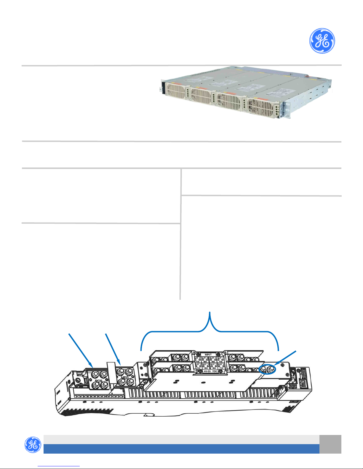
Step 4 - Connect DC Inputs
Feed each input from 80A breaker (shelf rating limited)
Lugs - 1/4” on 5/8” centers (not provided).
Torque to 65 in-lb (7.3 Nm) - 7/16” socket
CAUTION: Verify DC Input voltage and polarity with a voltmeter
Note: Input Feed Returns must be externally connected to DC
DC Inputs - Converter Inputs
Screwdrivers - Philips #1 and #2, Flat small
before proceeding.
Reference (CO) ground.
Output Return (Ground)
-48V Output
(L015 has all DC input feeds from the right as viewed from the rear)
4
POS NEG NEG POS
3
L014 shown
CP Converter Shelf - Quick Start Guide
Document 850033106 r04 2015 April
1
2
Chassis
Ground
1
Page 2

J4 1-Wire Battery Temp and Voltage Monitor
J1 Alarms and Inputs - page 4
J5 LAN Port
J2 External Alarm Inputs - page 4
J7 External Distribution Shelf.- page 4
Signal Connections
Step 5 - Set Jumpers - LAN Port and Relay per Galaxy Pulsar Edge Controller Quick Start Guide
Step 6 - Install Controller per Galaxy Pulsar Edge Controller Quick Start Guide
Step 7 - Install Signal and Communications Cables
Connectors are on rear.
1. J1-2 Alarms and Inputs - Connect to office alarms and signals.
See Information: Alarm Connections for Details
2. J5 LAN - Connect to Ethernet network.
3. J7 DIST - Connect to external distribution - if present.
RS-232 Craft port
Step 8 - Install 1-Wire Battery Temp and Voltage Monitor per Galaxy Pulsar Edge Controller Quick Start Guide - Optional
1. Connect 1-Wire Battery Temp and Voltage Monitor to J3
Step 9 - Install Converter s
1. Slide converter into its slot approximately 3/4 of the way.
2. Open the faceplate by sliding the faceplate latch to the left until the faceplate releases and
swings outward.
3. Slide the unit into the slot until it engages with the back of the shelf. Swing the faceplate closed
to fully seat the converter. Verify the faceplate is latched.
Latch
Step 10 - Initial Start Up
Verify that all AC, DC and Alarm connections are complete and secure. Turn on AC input breakers. If there are no alarms, make required
adjustments to the default settings on the controller for this installation.
Step 11 - Configure Controller per Galaxy Pulsar Edge Controller Quick Start Guide
Verify and edit controller basic configuration parameters per site engineering instructions.
2
CP Converter Shelf - Quick Start Guide
Document 850033106 r04 2015 April
Page 3

Pin
Controller
Information: Alarm Connections
See the Compact Power Line Brochure for details.
Alarm connections are on the rear of the shelf - J1 is Alarm Outputs and J2 is Alarm Inputs.
Change alarm descriptions via LAN port (Web pages) or Craft port (EasyView2) when required.
Connector J1 - Controller Variants
3C3R - 3 Alarm
Relays,
1
2
3
4
5
6
7
8
9
10
Color
0I5R_D - 5 Alarm
Relays
BK
Output: R3 = Rtn Input: PBT/TR Input: PBT/TR
BR
Output: R2 = Rtn Input: Hi Ext. Temp. Input: Hi Ext. Temp.
R
Output: R1 = Rtn Output: R1 = Rtn Input: Low Ext. Temp.
O
Output: PMN Rtn Output: PMN Rtn Input: Fan Fail
Y
Output: PMJ Rtn Output: PMJ Rtn Input: Hydrogen Present
G
Output: R3 = ACF Input: RTNS Input: Returns
BL
Output: R2 = RFA Input: Cust. Alrm 1 Input: Cust. Alrm 1
V
Output: R1 = BD Output: R1 = BD Input: Cust. Alrm 2
S
Output: PMN Output: PMN Input: Cust. Alrm 3
W
Output: PMJ Output: PMJ Input: Cust. Alrm 4
J1:
1. Includes a mixture of Alarm Inputs and / or Alarm Outputs depending on the controller model.
2. Connector Part:
Cvilux HDR10-CP35H
Alarm Inputs:
1. “dry” contacts, apply no voltage.
2. Return for all alarm inputs is pin 6.
Alarm Outputs: relays contacts.
J2 - All Controllers
9C0R_USB - 9 Inputs Color All
Y
Input: SPD Fail
S
O
Input: AUX MAJ
V
Input: Air Cond. Fail
W
Input: Door Open
BL
BR
BK
J2:
1. Includes 4 Alarm Inputs.
2. Connector Parts: Molex
39-01-2086 Housing
39-00-0087 Contacts
Alarm Inputs:
1. Contact closures or opens to -48V.
2. Pins 6, 7, and 8 provide -48V for these alarm inputs.
--
-48V
-48V
-48V
Information: Connections - External Distribution - J7
J7 Pin Wire Color Description
1 BK FAJ
2 BR Coil Rtn
3 R LVD_NC
4 O LVD_NO
5 Y Shunt 6 G OS
7 BL Coil 1
8 V Coil 2
9 S LVD Status Return
10 W Shunt +
J7:
1. Connector P/N
Cvilux HDR10-CP35H
CP Converter Shelf - Quick Start Guide
Document 850033106 r04 2015 April
1
3
Page 4

Specifications and Application
Specifications and ordering information are in the Compact Power Line (CPL) Brochure available at www.gecriticalpower.com
Equipment and subassembly ports: 1. are suitable for connection to intra-building or unexposed wiring or cabling;
2. can be connected to shielded intra-building cabling grounded at both ends.
Grounding / Bonding Network – Connect to an Isolated Ground Plane (Isolated Bonding Network) or an Integrated Ground Plane (Mesh-
Bonding Network or Common Bonding Network).
Installation Environment - Install in Network Telecommunication Facilities, OSP, or where NEC applies.
DC return may be either Isolated DC return (DC-I) or Common DC return (DC-C).
Reference Documents
These documents are available at www.gecriticalpower.com.
Document Title
850035894 Galaxy Pulsar Edge Quick Start Guide
CC848836981 Galaxy Pulsar Edge Controller Family Product Manual
Compact Power Line (CPL) Brochure
2
4
GE ● 601 Shiloh Rd. ● Plano, TX 75074 ● 1- 888-546-3243
CP Converter Shelf - Quick Start Guide
Document 850033106 r04 2015 April
www.gecriticalpower.com
 Loading...