

Page 1

GE Healthcare
Corometrics™ 250cx Series Monitor
Service Manual
Corometrics 250cx Series Monitor English
2036947-001 Revision J
© 2013 General Electric Company.
All Rights Reserved
Page 2

Page 3
GE Healthcare
Corometrics™ 250cx Series Monitor
Service Manual
Corometrics 250cx Series Monitor English
2036947-001 Revision J
© 2013 General Electric Company.
All Rights Reserved
Page 4

© 2005 - 2013 by General Electric Company
All rights reserved. General Electric Company reserves the right to make changes in specications and features
shown herein, or discontinue the product described at any time without notice or obligation. Contact your
GE Representative for the most current information. SuperSTAT™ is the property of GE MEDICAL SYSTEMS
Information Technologies, a GE Healthcare Company which is a division of General Electric Corporation. GE and
GE Monogram are trademarks of General Electric Company. All other company and product names mentioned
may be trademarks of the companies with which they are associated.
Warranty
This product is sold by GE Healthcare with a GE repair warranty period of 12-month to cover labor and parts*
(except for the expendable parts like fuses or batteries which have a 30-day warranty) under the terms and
conditions set forth in the GE Healthcare Warranty Statement presented to the customer at the point of sale.
* The warranty time may vary in some regions. Refer to the warranty information provided at the point of sale.
Page 5

ПРЕДУПРЕЖДЕНИЕ
Това упътване за работа е налично само на английски език.
(BG)
(ZH-CN)
(ZH-HK)
• Ако доставчикът на услугата на клиента изиска друг език, задължение на клиента е
да осигури превод.
• Не използвайте оборудването, преди да сте се консултирали и разбрали упътването
за работа.
• Неспазването на това предупреждение може да доведе до нараняване на
доставчика на услугата, оператора или пациентa в резултат на токов удар,
механична или друга опасност.
警告
本维修手册仅提供英文版本。
• 如果客户的维修服务人员需要非英文版本,则客户需自行提供翻译服务。
• 未详细阅读和完全理解本维修手册之前,不得进行维修。
• 忽略本警告可能对维修服务人员、操作人员或患者造成电击、机械伤害或其他形式的
伤害。
警告
本服務手冊僅提供英文版本。
• 倘若客戶的服務供應商需要英文以外之服務手冊,客戶有責任提供翻譯服務。
• 除非已參閱本服務手冊及明白其內容,否則切勿嘗試維修設備。
• 不遵從本警告或會令服務供應商、網絡供應商或病人受到觸電、機械性或其他的危
險。
(ZH-TW)
(HR)
警告
本維修手冊僅有英文版。
• 若客戶的維修廠商需要英文版以外的語言,應由客戶自行提供翻譯服務。
• 請勿試圖維修本設備,除非您已查閱並瞭解本維修手冊。
• 若未留意本警告,可能導致維修廠商、操作員或病患因觸電、機械或其他危險而受
傷。
UPOZORENJE
Ovaj servisni priručnik dostupan je na engleskom jeziku.
• Ako davatelj usluge klijenta treba neki drugi jezik, klijent je dužan osigurati prijevod.
• Ne pokušavajte servisirati opremu ako niste u potpunosti pročitali i razumjeli ovaj
servisni priručnik.
• Zanemarite li ovo upozorenje, može doći do ozljede davatelja usluge, operatera ili
pacijenta uslijed strujnog udara, mehaničkih ili drugih rizika.
Page 6
VÝSTRAHA
Tento provozní návod existuje pouze v anglickém jazyce.
(CS)
(DA)
(NL)
• V případě, že externí služba zákazníkům potřebuje návod v jiném jazyce, je zajištění
překladu do odpovídajícího jazyka úkolem zákazníka.
• Nesnažte se o údržbu tohoto zařízení, aniž byste si přečetli tento provozní návod a
pochopili jeho obsah.
• V případě nedodržování této výstrahy může dojít k poranění pracovníka prodejního
servisu, obslužného personálu nebo pacientů vlivem elektrického proudu, respektive
vlivem mechanických či jiných rizik.
ADVARSEL
Denne servicemanual ndes kun på engelsk.
• Hvis en kundes tekniker har brug for et andet sprog end engelsk, er det kundens ansvar
at sørge for oversættelse.
• Forsøg ikke at servicere udstyret uden at læse og forstå denne servicemanual.
• Manglende overholdelse af denne advarsel kan medføre skade på grund af elektrisk
stød, mekanisk eller anden fare for teknikeren, operatøren eller patienten.
WAARSCHUWING
Deze onderhoudshandleiding is enkel in het Engels verkrijgbaar.
• Als het onderhoudspersoneel een andere taal vereist, dan is de klant verantwoordelijk
voor de vertaling ervan.
• Probeer de apparatuur niet te onderhouden alvorens deze onderhoudshandleiding werd
geraadpleegd en begrepen is.
• Indien deze waarschuwing niet wordt opgevolgd, zou het onderhoudspersoneel, de
operator of een patiënt gewond kunnen raken als gevolg van een elektrische schok,
mechanische of andere gevaren.
(EN)
(ET)
WARNING:
This service manual is available in English only.
• If a customer’s service provider requires a language other than English, it is the
customer’s responsibility to provide translation services.
• Do not attempt to service the equipment unless this service manual has been consulted
and is understood.
• Failure to heed this warning may result in injury to the service provider, operator, or
patient from electric shock, mechanical hazards, or other hazards.
HOIATUS
See teenindusjuhend on saadaval ainult inglise keeles
• Kui klienditeeninduse osutaja nõuab juhendit inglise keelest erinevas keeles, vastutab
klient tõlketeenuse osutamise eest.
• Ärge üritage seadmeid teenindada enne eelnevalt käesoleva teenindusjuhendiga
tutvumist ja sellest aru saamist.
• Käesoleva hoiatuse eiramine võib põhjustada teenuseosutaja, operaatori või patsiendi
vigastamist elektrilöögi, mehaanilise või muu ohu tagajärjel.
Page 7
VAROITUS
Tämä huolto-ohje on saatavilla vain englanniksi.
(FI)
(FR)
(DE)
• Jos asiakkaan huoltohenkilöstö vaatii muuta kuin englanninkielistä materiaalia,
tarvittavan käännöksen hankkiminen on asiakkaan vastuulla.
• Älä yritä korjata laitteistoa ennen kuin olet varmasti lukenut ja ymmärtänyt tämän
huolto-ohjeen.
• Mikäli tätä varoitusta ei noudateta, seurauksena voi olla huoltohenkilöstön, laitteiston
käyttäjän tai potilaan vahingoittuminen sähköiskun, mekaanisen vian tai muun
vaaratilanteen vuoksi.
ATTENTION
Ce manuel d’installation et de maintenance est disponible uniquement en anglais.
• Si le technicien d’un client a besoin de ce manuel dans une langue autre que l’anglais, il
incombe au client de le faire traduire.
• Ne pas tenter d’intervenir sur les équipements tant que ce manuel d’installation et de
maintenance n’a pas été consulté et compris.
• Le non-respect de cet avertissement peut entraîner chez le technicien, l’opérateur ou le
patient des blessures dues à des dangers électriques, mécaniques ou autres.
WARNUNG
Diese Serviceanleitung existiert nur in englischer Sprache.
• Falls ein fremder Kundendienst eine andere Sprache benötigt, ist es Aufgabe des Kunden
für eine entsprechende Übersetzung zu sorgen.
• Versuchen Sie nicht diese Anlage zu warten, ohne diese Serviceanleitung gelesen und
verstanden zu haben.
• Wird diese Warnung nicht beachtet, so kann es zu Verletzungen des
Kundendiensttechnikers, des Bedieners oder des Patienten durch Stromschläge,
mechanische oder sonstige Gefahren kommen.
(EL)
ΠΡΟΕΙΔΟΠΟΙΗΣΗ
Το παρόν εγχειρίδιο σέρβις διατίθεται μόνο στα αγγλικά.
• Εάν ο τεχνικός σέρβις ενός πελάτη απαιτεί το παρόν εγχειρίδιο σε γλώσσα εκτός των
αγγλικών, αποτελεί ευθύνη του πελάτη να παρέχει τις υπηρεσίες μετάφρασης.
• Μην επιχειρήσετε την εκτέλεση εργασιών σέρβις στον εξοπλισμό αν δεν έχετε
συμβουλευτεί και κατανοήσει το παρόν εγχειρίδιο σέρβις.
• Αν δεν προσέξετε την προειδοποίηση αυτή, ενδέχεται να προκληθεί τραυματισμός στον
τεχνικό σέρβις, στο χειριστή ή στον ασθενή από ηλεκτροπληξία, μηχανικούς ή άλλους
κινδύνους.
Page 8
FIGYELMEZTETÉS
Ezen karbantartási kézikönyv kizárólag angol nyelven érhető el.
(HU)
(IS)
(IT)
• Ha a vevő szolgáltatója angoltól eltérő nyelvre tart igényt, akkor a vevő felelőssége a
fordítás elkészíttetése.
• Ne próbálja elkezdeni használni a berendezést, amíg a karbantartási kézikönyvben
leírtakat nem értelmezték.
• Ezen gyelmeztetés gyelmen kívül hagyása a szolgáltató, működtető vagy a beteg
áramütés, mechanikai vagy egyéb veszélyhelyzet miatti sérülését eredményezheti.
AÐVÖRUN
Þessi þjónustuhandbók er aðeins fáanleg á ensku.
• Ef að þjónustuveitandi viðskiptamanns þarfnast annas tungumáls en ensku, er það
skylda viðskiptamanns að skaa tungumálaþjónustu.
• Reynið ekki að afgreiða tækið nema að þessi þjónustuhandbók hefur verið skoðuð og
skilin.
• Brot á sinna þessari aðvörun getur leitt til meiðsla á þjónustuveitanda, stjórnanda eða
sjúklings frá raosti, vélrænu eða öðrum áhættum.
AVVERTENZA
Il presente manuale di manutenzione è disponibile soltanto in lingua inglese.
• Se un addetto alla manutenzione richiede il manuale in una lingua diversa, il cliente è
tenuto a provvedere direttamente alla traduzione.
• Procedere alla manutenzione dell’apparecchiatura solo dopo aver consultato il presente
manuale ed averne compreso il contenuto.
• Il mancato rispetto della presente avvertenza potrebbe causare lesioni all’addetto alla
manutenzione, all’operatore o ai pazienti provocate da scosse elettriche, urti meccanici
o altri rischi.
(JA)
(KO)
このサービスマニュアルには英語版しかありません。
• サービスを担当される業者が英語以外の言語を要求される場合、翻訳作業はその業
者の責任で行うものとさせていただきます。
• このサービスマニュアルを熟読し理解せずに、装置のサービスを行わないでくださ
い。
• この警告に従わない場合、サービスを担当される方、操作員あるいは患者さんが、
感電や機械的又はその他の危険により負傷する可能性があります。
경고
본 서비스 매뉴얼은 영어로만 이용하실 수 있습니다.
• 고객의 서비스 제공자가 영어 이외의 언어를 요구할 경우, 번역 서비스를 제공하는
것은 고객의 책임입니다.
• 본 서비스 매뉴얼을 참조하여 숙지하지 않은 이상 해당 장비를 수리하려고 시도하지
마십시오.
• 본 경고 사항에 유의하지 않으면 전기 쇼크, 기계적 위험, 또는 기타 위험으로 인해
서비스 제공자, 사용자 또는 환자에게 부상을 입힐 수 있습니다.
Page 9
BRĪDINĀJUMS
Šī apkopes rokasgrāmata ir pieejama tikai angļu valodā.
(LV)
(LT)
(NO)
• Ja klienta apkopes sniedzējam nepieciešama informācija citā valodā, klienta pienākums
ir nodrošināt tulkojumu.
• Neveiciet aprīkojuma apkopi bez apkopes rokasgrāmatas izlasīšanas un saprašanas.
• Šī brīdinājuma neievērošanas rezultātā var rasties elektriskās strāvas trieciena,
mehānisku vai citu faktoru izraisītu traumu risks apkopes sniedzējam, operatoram vai
pacientam.
ĮSPĖJIMAS
Šis eksploatavimo vadovas yra tik anglų kalba.
• Jei kliento paslaugų tiekėjas reikalauja vadovo kita kalba – ne anglų, suteikti vertimo
paslaugas privalo klientas.
• Nemėginkite atlikti įrangos techninės priežiūros, jei neperskaitėte ar nesupratote šio
eksploatavimo vadovo.
• Jei nepaisysite šio įspėjimo, galimi paslaugų tiekėjo, operatoriaus ar paciento sužalojimai
dėl elektros šoko, mechaninių ar kitų pavojų.
ADVARSEL
Denne servicehåndboken nnes bare på engelsk.
• Hvis kundens serviceleverandør har bruk for et annet språk, er det kundens ansvar å
sørge for oversettelse.
• Ikke forsøk å reparere utstyret uten at denne servicehåndboken er lest og forstått.
• Manglende hensyn til denne advarselen kan føre til at serviceleverandøren, operatøren
eller pasienten skades på grunn av elektrisk støt, mekaniske eller andre farer.
(PL)
(PT-BR)
OSTRZEŻENIE
Niniejszy podręcznik serwisowy dostępny jest jedynie w języku angielskim.
• Jeśli serwisant klienta wymaga języka innego niż angielski, zapewnienie usługi
tłumaczenia jest obowiązkiem klienta.
• Nie próbować serwisować urządzenia bez zapoznania się z niniejszym podręcznikiem
serwisowym i zrozumienia go.
• Niezastosowanie się do tego ostrzeżenia może doprowadzić do obrażeń serwisanta,
operatora lub pacjenta w wyniku porażenia prądem elektrycznym, zagrożenia
mechanicznego bądź innego.
AVISO
Este manual de assistência técnica encontra-se disponível unicamente em inglês.
• Se outro serviço de assistência técnica solicitar a tradução deste manual, caberá ao
cliente fornecer os serviços de tradução.
• Não tente reparar o equipamento sem ter consultado e compreendido este manual de
assistência técnica.
• A não observância deste aviso pode ocasionar ferimentos no técnico, operador ou
paciente decorrentes de choques elétricos, mecânicos ou outros.
Page 10
ATENÇÃO
Este manual de assistência técnica só se encontra disponível em inglês.
(PT-PT)
(RO)
(RU)
• Se qualquer outro serviço de assistência técnica solicitar este manual noutro idioma, é
da responsabilidade do cliente fornecer os serviços de tradução.
• Não tente reparar o equipamento sem ter consultado e compreendido este manual de
assistência técnica.
• O não cumprimento deste aviso pode colocar em perigo a segurança do técnico, do
operador ou do paciente devido a choques eléctricos, mecânicos ou outros.
ATENŢIE
Acest manual de service este disponibil doar în limba engleză.
• Dacă un furnizor de servicii pentru clienţi necesită o altă limbă decât cea engleză, este
de datoria clientului să furnizeze o traducere.
• Nu încercaţi să reparaţi echipamentul decât ulterior consultării şi înţelegerii acestui
manual de service.
• Ignorarea acestui avertisment ar putea duce la rănirea depanatorului, operatorului sau
pacientului în urma pericolelor de electrocutare, mecanice sau de altă natură.
ОСТОРОЖНО!
Данное руководство по техническому обслуживанию представлено только на
английском языке.
• Если сервисному персоналу клиента необходимо руководство не на английском, а на
каком-то другом языке, клиенту следует самостоятельно обеспечить перевод.
• Перед техническим обслуживанием оборудования обязательно обратитесь к
данному руководству и поймите изложенные в нем сведения.
• Несоблюдение требований данного предупреждения может привести к тому, что
специалист по техобслуживанию, оператор или пациент получит удар электрическим
током, механическую травму или другое повреждение.
(SR)
(SK)
UPOZORENJE
Ovo servisno uputstvo je dostupno samo na engleskom jeziku.
• Ako klijentov serviser zahteva neki drugi jezik, klijent je dužan da obezbedi prevodilačke
usluge.
• Ne pokušavajte da opravite uređaj ako niste pročitali i razumeli ovo servisno uputstvo.
• Zanemarivanje ovog upozorenja može dovesti do povređivanja servisera, rukovaoca ili
pacijenta usled strujnog udara ili mehaničkih i drugih opasnosti.
UPOZORNENIE
Tento návod na obsluhu je k dispozícii len v angličtine.
• Ak zákazníkov poskytovateľ služieb vyžaduje iný jazyk ako angličtinu, poskytnutie
prekladateľských služieb je zodpovednosťou zákazníka.
• Nepokúšajte sa o obsluhu zariadenia, kým si neprečítate návod na obluhu a
neporozumiete mu.
• Zanedbanie tohto upozornenia môže spôsobiť zranenie poskytovateľa služieb,
obsluhujúcej osoby alebo pacienta elektrickým prúdom, mechanické alebo iné
ohrozenie.
Page 11
ATENCION
Este manual de servicio sólo existe en inglés.
(ES)
(SV)
(SL)
• Si el encargado de mantenimiento de un cliente necesita un idioma que no sea el inglés,
el cliente deberá encargarse de la traducción del manual.
• No se deberá dar servicio técnico al equipo, sin haber consultado y comprendido este
manual de servicio.
• La no observancia del presente aviso puede dar lugar a que el proveedor de servicios, el
operador o el paciente sufran lesiones provocadas por causas eléctricas, mecánicas o
de otra naturaleza.
VARNING
Den här servicehandboken nns bara tillgänglig på engelska.
• Om en kunds servicetekniker har behov av ett annat språk än engelska, ansvarar
kunden för att tillhandahålla översättningstjänster.
• Försök inte utföra service på utrustningen om du inte har läst och förstår den här
servicehandboken.
• Om du inte tar hänsyn till den här varningen kan det resultera i skador på
serviceteknikern, operatören eller patienten till följd av elektriska stötar, mekaniska faror
eller andra faror.
OPOZORILO
Ta servisni priročnik je na voljo samo v angleškem jeziku.·
• Če ponudnik storitve stranke potrebuje priročnik v drugem jeziku, mora stranka
zagotoviti prevod.·
• Ne poskušajte servisirati opreme, če tega priročnika niste v celoti prebrali in razumeli.·
• Če tega opozorila ne upoštevate, se lahko zaradi električnega udara, mehanskih ali
drugih nevarnosti poškoduje ponudnik storitev, operater ali bolnik.
(TR)
DİKKAT
Bu servis kılavuzunun sadece ingilizcesi mevcuttur.
• Eğer müşteri teknisyeni bu kılavuzu ingilizce dışında bir başka lisandan talep ederse,
bunu tercüme ettirmek müşteriye düşer.
• Servis kılavuzunu okuyup anlamadan ekipmanlara müdahale etmeyiniz.
• Bu uyarıya uyulmaması, elektrik, mekanik veya diğer tehlikelerden dolayı teknisyen,
operatör veya hastanın yaralanmasına yol açabilir.
Page 12

Page 13

Table of Contents
Compliance ........................................................................................................................................................................xviii
Components of the Certied Systems ..................................................................................................................xviii
Component Description ...............................................................................................................................................xviii
Exceptions ..........................................................................................................................................................................xviii
Monitor System EMC: Immunity Performance ..................................................................................................xviii
About this Manual .................................................................................................................. 1
Scope and Intended Users ............................................................................................................................................. 1
Conventions ............................................................................................................................................................................ 1
User Responsibility .............................................................................................................................................................. 1
References ...............................................................................................................................................................................2
Denitions of Terms ............................................................................................................................................................ 2
Symbols .................................................................................................................................................................................... 3
Important Safety Information ............................................................................................ 5
Warnings, Cautions and Notes ...................................................................................................................................... 6
Electromagnetic Interference ........................................................................................................................................9
Chapter 1: System Description ......................................................................................... 11
1.1 System Overview ....................................................................................................................................................... 11
1.2 Front Panel Controls, Indicators, and Connectors ..................................................................................... 13
1.3 Display Description ................................................................................................................................................... 15
1.3.1 Primary Labor Parameters ..................................................................................................................... 16
1.3.2 Additional Parameters ............................................................................................................................. 16
1.3.3 Waveform ....................................................................................................................................................... 16
1.3.4 Time ................................................................................................................................................................... 16
1.3.5 Softkeys ........................................................................................................................................................... 16
1.4 Rear Panel Descriptions ......................................................................................................................................... 19
1.5 Peripherals Description ........................................................................................................................................... 21
1.5.1 CorometricsTM 340 Telemetry and Mini Telemetry ..................................................................... 21
1.5.2 Quantitative Sentinel/Perinatal System ........................................................................................... 22
1.5.3 Exergen® TAT-5000
TM .............................................................................................................................................................. 22
© 2013 by General Electric Company. All rights reserved. 2036947-001 xiii
Page 14

Table of Contents
1.5.4 DINAMAP® Models PRO Series 100-400 and ProCare ............................................................... 22
1.6 Theory of Operation ................................................................................................................................................ 23
1.6.1 Digital System Processor (DSP) / Display Board ........................................................................... 23
1.6.2 Main Board ..................................................................................................................................................... 25
1.6.3 User-Interface Keypad & Volume/Alarm Keypad Boards ........................................................ 26
1.6.4 Video Decoder Board ................................................................................................................................ 26
1.6.5 Recorder Board ............................................................................................................................................ 26
1.6.6 Communications Board ........................................................................................................................... 26
1.6.7 MSpO2 Connector Board ......................................................................................................................... 26
1.6.8 MSpO2 Carrier Board ................................................................................................................................. 27
1.6.9 FECG/UA Board.............................................................................................................................................27
1.6.10 MECG Board ................................................................................................................................................ 27
1.6.11 Dual Ultrasound Board .......................................................................................................................... 27
1.6.12 Isolated Power Supply Board .............................................................................................................. 28
1.6.13 Front-End Motherboard .........................................................................................................................28
1.6.14 Memory Battery ........................................................................................................................................ 28
Chapter 2: Installation ........................................................................................................ 29
2.1 Time Required for Installation .............................................................................................................................. 29
2.2 Environmental Requirements .............................................................................................................................. 29
2.3 Tool Requirements .................................................................................................................................................... 29
2.4 Installation Procedure ............................................................................................................................................. 29
2.4.1 Strip Chart Recorder Paper Load ......................................................................................................... 29
2.4.2 Peripheral Connections ............................................................................................................................ 31
2.4.3 Power Cord Attachment...........................................................................................................................31
2.4.4 System Conguration ............................................................................................................................... 31
Chapter 3: Maintenance and Checkout .......................................................................... 35
3.1 Procedures Schedule ............................................................................................................................................... 35
3.1.1 Environmental Requirements ................................................................................................................ 36
3.2 Tool Requirements .................................................................................................................................................... 36
3.3 Maintenance and Checkout Procedures ........................................................................................................ 36
3.3.1 Visual Inspection.......................................................................................................................................... 36
3.3.2 Cleaning (Thermal Print Head) .............................................................................................................. 37
3.3.3 Transducer Checks ..................................................................................................................................... 37
3.3.4 Functional Checks ....................................................................................................................................... 38
3.3.5 Pattern Memory Check ............................................................................................................................. 49
3.3.6 NIBP Calibration Check ............................................................................................................................. 52
3.3.7 Electrical Safety Tests ............................................................................................................................... 52
xiv 2036947-001 © 2013 by General Electric Company. All rights reserved.
Page 15

Table of Contents
Chapter 4: Calibration ......................................................................................................... 55
4.1 Calibration Schedule ................................................................................................................................................ 55
4.2 Environmental Requirements .............................................................................................................................. 56
4.3 Tool Requirements .................................................................................................................................................... 56
4.4 Calibration Procedures ........................................................................................................................................... 56
4.4.1 NIBP Calibration Check ............................................................................................................................. 56
4.4.2 Recorder Photosensors Check .............................................................................................................. 59
4.4.3 Recorder Calibration (osets) Check .................................................................................................. 61
Chapter 5: Diagnostics and Troubleshooting ................................................................. 63
5.1 General Troubleshooting Table ........................................................................................................................... 63
5.2 Ultrasound Troubleshooting Table .................................................................................................................... 67
5.3 FECG Troubleshooting Table ................................................................................................................................ 69
5.4 External Uterine Activity Troubleshooting Table.........................................................................................70
5.5 Internal Uterine Activity Troubleshooting Table .........................................................................................72
5.6 MECG Troubleshooting Table ............................................................................................................................... 73
5.7 Blood Pressure Troubleshooting Table ............................................................................................................ 73
5.8 Maternal Pulse Oximetry Troubleshooting Table ....................................................................................... 75
5.9 Main Board Troubleshooting – Voltage Checks ..........................................................................................76
5.10 FECG/UA Board Troubleshooting – Voltage Adjustments .................................................................... 77
5.11 Recorder Troubleshooting .................................................................................................................................. 77
5.11.1 Vertical Oset Adjustment ................................................................................................................... 77
5.11.2 Horizontal Oset Adjustment .............................................................................................................. 79
5.11.3 Light Printing ............................................................................................................................................... 80
Chapter 6: Repair and Replacement Procedures ........................................................... 85
6.1 Top Cover, Top Cover Gasket, and Timekeeping RAM Chip Replacement ...................................... 86
6.2 Speaker Replacement ............................................................................................................................................. 87
6.3 DSP/Display Board Replacement.......................................................................................................................88
6.4 Communication Board Replacement ...............................................................................................................89
6.5 Pneumatics Assembly Replacement ................................................................................................................ 90
6.6 Main Board Replacement ...................................................................................................................................... 92
6.7 Display Assembly Replacement ......................................................................................................................... 93
6.8 Power Switch Assembly Replacement ............................................................................................................ 95
6.9 Trim Knob Control Assembly Replacement .................................................................................................. 96
6.10 Keypads Replacement ......................................................................................................................................... 97
6.11 Main Power Supply / Fan Replacement ....................................................................................................... 99
© 2013 by General Electric Company. All rights reserved. 2036947-001 xv
Page 16

Table of Contents
Chapter 7: Service Parts ................................................................................................... 117
6.12 Dual Ultrasound Board Replacement .........................................................................................................101
6.13 FECG/UA Board and MECG Board Replacement ....................................................................................102
6.14 SpO2 Carrier Board (with Nellcor/Masimo SpO2 Module) Replacement ....................................103
6.15 Isolated Power Supply Board Replacement .............................................................................................104
6.16 Front-end Motherboard Replacement ........................................................................................................105
6.17 Recorder Assembly and Recorder Door Button Replacement ........................................................107
6.18 Recorder Board Replacement .........................................................................................................................109
6.19 Recorder Stepper Motor Replacement .......................................................................................................110
6.20 Recorder Paper-Out/Paper-Low Photosensor Replacement ...........................................................111
6.21 Recorder Paper-Loading Photosensor Replacement ..........................................................................113
6.22 Recorder Thermal Print Head Replacement ............................................................................................114
6.23 Front Bezel Replacement ..................................................................................................................................115
7.1 Illustrated Parts ........................................................................................................................................................118
7.2 Labels ............................................................................................................................................................................123
7.3 Power Cords ...............................................................................................................................................................124
7.4 FRU List .........................................................................................................................................................................125
Appendix A: Technical Specications ............................................................................. 131
A.1 General Product Specications ........................................................................................................................132
A.2 Strip Chart Recorder Specications ................................................................................................................133
A.3 Operating Modes Specications ......................................................................................................................134
Appendix B: Alarm Summary .......................................................................................... 141
Appendix C: Electromagnetic Compatibility ................................................................ 143
C.1 Manufacturer’s Guidance and Declaration – Electromagnetic Emissions ...................................143
C.2 Manufacturer’s Guidance and Declaration – Electromagnetic Immunity ...................................144
C.3 Recommended Separation Distances ...........................................................................................................146
C.4 Compliant Cables and Accessories .................................................................................................................146
Appendix D: PS320 Fetal Simulator Setup ..................................................................... 149
D.1 Parts Required ..........................................................................................................................................................149
D.2 PS320 Fetal Simulator Setup .............................................................................................................................150
Appendix E: Service Mode Screens .................................................................................. 153
xvi 2036947-001 © 2013 by General Electric Company. All rights reserved.
Page 17

Table of Contents
E.1 Service Lock Screen ................................................................................................................................................154
E.2 Install Options Screens ..........................................................................................................................................155
E.3 Printing Setup Information ..................................................................................................................................159
E.4 Communications Setup Screen .........................................................................................................................159
E.5 Error Log Screen .......................................................................................................................................................160
E.6 Diagnostic Control Screen ...................................................................................................................................161
E.7 J102 Screen ................................................................................................................................................................162
E.8 NIBP Calibration Screen ........................................................................................................................................163
E.9 Setup Screen Defaults ...........................................................................................................................................163
E.9.1 Operator Setup Screens .........................................................................................................................164
E.9.2 Service Mode Screens .............................................................................................................................167
Appendix F: CPU Software Upgrade ................................................................................169
F.1 Tool Requirement .....................................................................................................................................................169
F.2 Upgrade Procedure .................................................................................................................................................169
Appendix G: CorometricsTM 325 Simulator Setup and Use .......................................... 171
G.1 Simulator Setup .......................................................................................................................................................171
G.2 Alarms Check ............................................................................................................................................................171
G.3 MECG Input Check ..................................................................................................................................................174
G.4 FECG Input Check....................................................................................................................................................175
G.5 Ultrasound Input Check .......................................................................................................................................177
G.6 Uterine Activity Check ..........................................................................................................................................178
G.7 Pattern Memory Check ........................................................................................................................................179
G.8 Dual Heart Rate Check (Non-Pattern, FECG/US Modes) .......................................................................180
G.9 Dual Heart Rate Check (Non-Pattern, Dual US Modes) .........................................................................181
G.10 Fetal Movement Detection Check ................................................................................................................182
© 2013 by General Electric Company. All rights reserved. 2036947-001 xvii
Page 18

Compliance
A GE brand Corometrics™ 250cx Series Monitor bears CE mark CE-0459 indicating its conformity with the
provisions of the Council Directive 93/42/EEC concerning medical devices and fullls the essential requirements
of Annex I of this directive.
The device is manufactured in India; the CE mark is applied under the authority of Notied Body GMED (0459).
The country of manufacture and appropriate Notied Body can be found on the equipment labeling.
The product complies with the requirements of standard EN 60601-1-2 “Electromagnetic Compatibility—
Medical Electrical Equipment” and standard EN 60601-1 “General Requirements for Safety.”
Components of the Certied Systems
The IEC electromagnetic compatibility (EN) standards require individual equipment (components and
accessories) to be congured as a system for evaluation. For systems that include a number of dierent
equipment that perform a number of functions, one of each type of equipment shall be included in the
evaluation.
The equipment listed below is representative of all possible combinations. For individual equipment
certication, refer to the appropriate declarations of conformity.
Component Description
• 250cx Series Maternal/Fetal Monitor
• Model 146 Fetal Acoustic Stimulator
• Intrauterine Pressure Transducer
• FECG Cable/Legplate
• Ultrasound Transducers (x2)
• Blood Pressure Hose and Cu
• MSpO2 Interconnect Cable and Sensor
• MECG Cable
• FECG/MECG Adapter Cable
• Remote Event Marker
• RS-232C Interconnect Cables (x3)
• Central Nurses Station Interconnect Cable
• Model 2116B Keyboard and Interconnect Cable
• Model 1563AAO Telemetry Cable
• Exergen® TAT-5000
• External 15” display
™
Exceptions
None
Monitor System EMC: Immunity Performance
Be aware that adding accessories or components, or modifying the medical device or system may degrade the
EMI performance. Consult with qualied personnel regarding changes to the system conguration.
xviii 2036947-001 © 2013 by General Electric Company. All rights reserved.
Page 19
About this Manual
Scope and Intended Users
This service manual describes the installation, maintenance, checkout, calibration and repair of the
CorometricsTM 250cx Series monitor. The intended users for this service manual are biomedical engineering
service providers of the hospitals and GE service personnel.
Conventions
WARNING:
A WARNING statement is used when the possibility of injury to the patient or the operator
exists.
CAUTION:
A CAUTION statement is used when the possibility of damage to the equipment exists.
SENSITIVE TO ELECTROSTATIC DISCHARGE CAUTION
An electrostatic discharge (ESD) Susceptibility symbol is displayed to alert service personnel
that the part(s) are sensitive to electrostatic discharge and that static control procedures must
be used to prevent damage to the equipment.
User Responsibility
This Product will perform in conformity with the description thereof contained in this manual and
accompanying labels and/or inserts, when assembled, operated, maintained and repaired in accordance
with the instructions provided. This Product must be checked periodically. A defective Product should not be
used. Parts that are broken, missing, plainly worn, distorted or contaminated should be replaced immediately.
Should such repair or replacement become necessary, GE Healthcare recommends that a telephone or
written request for service advice be made to the nearest GE Healthcare Regional Service Center. This Product
or any of its parts should not be repaired other than in accordance with written instructions provided by GE
Healthcare and by GE Healthcare trained personnel. The Product must not be altered without GE Healthcare’s
prior written approval. The user of this Product shall have the sole responsibility for any malfunction that
results from improper use, faulty maintenance, improper repair, damage or alteration by anyone other than GE
Healthcare.
This Product is intended for use by clinical professionals who are expected to know the medical procedures,
practices, and terminology required to monitor obstetrical patients. This manual documents all possible
parameters available in the CorometricsTM 250cx Series monitor. It is the responsibility of each hospital to
ensure that the Labor and Delivery sta is trained in all aspects of the selected model. The CorometricsTM 250cx
Series monitor is designed to assist the perinatal sta by providing information regarding the clinical status of
the mother and fetus during labor. The monitor does not replace observation and evaluation of the mother and
fetus at regular intervals, by a qualied care provider, who will make diagnoses and decide on treatments or
© 2013 by General Electric Company. All rights reserved. 2036947-001 1
Page 20
About this Manual
interventions. Visual assessment of the monitor display and strip chart must be combined with knowledge of
patient history and risk factors to properly care for the mother and fetus.
WARNING:
This device shall not be repaired other than in accordance with written instructions provided
by GE Healthcare and by GE Healthcare trained personnel.
CAUTION:
Untied States federal law restricts this device to sale by or on the order of a licensed medical
practitioner.
References
The following table lists other manuals pertaining to the CorometricsTM 250cx Series monitor service manual:
References Orderable Part Number
CorometricsTM 250cx Series Monitor Operator’s Manual (English) 2036946-001
Corometrics
Mini Telemetry System Service Manual 2049821-001
TM
Model 340 Service Manual 2006920-001
Fluke® PS320 Fetal Simulator User’s Manual
Maternal/Fetal Monitoring Clinical Application Operator’s Manual 15457AA
CorometricsTM Fetal Acoustic Stimulator Operator’s Manual 1168AA
Visit www.ukebiomedical.com
Denitions of Terms
Term Denition
BPM Beat Per Minute
ECG Electrocardiogram
ESD Electro Static Discharge
FECG Fetal Electrocardiogram
FHR Fetal Heart Rate
FAST Fetal Acoustic Stimulation Test
FMD Fetal Movement Detection
HBC Heart Beat Coincidence
INOP Inoperable
IUPC Intra-Uterine Pressure Catheter
LCD Liquid Crystal Display
MECG Maternal Electrocardiogram
NIBP Non-Invasive Blood Pressure
REM Remote Event Marker
SpO2 Pulse Oximeter Oxygen Saturation
TOCO Non-invasive method of measuring uterine activity
2 2036947-001 © 2013 by General Electric Company. All rights reserved.
Page 21
About this Manual
Term Denition
UA Uterine Activity
US Ultrasound
Symbols
This section identies the symbols that are displayed on the CorometricsTM 250cx Series monitor:
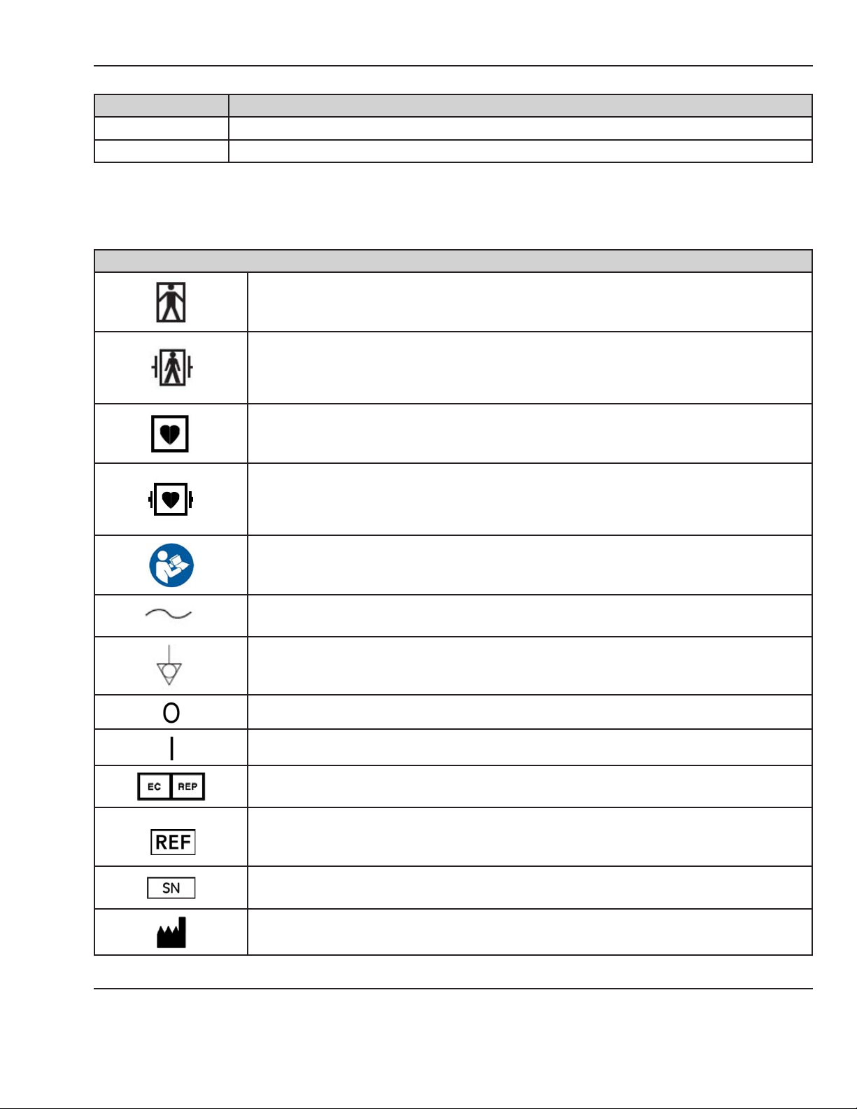
Equipment Symbols
TYPE BF EQUIPMENT: Type BF equipment is suitable for intentional external and internal
application to the patient, excluding direct cardiac application. Type BF equipment has an
F-type applied part.
DEFIBRILLATOR-PROOF TYPE BF EQUIPMENT: Type BF equipment is suitable for intentional
external and internal application to the patient, excluding direct cardiac application. Type BF
equipment is type B equipment with an F-type isolated (oating) part. The paddles indicate
the equipment is debrillator proof.
TYPE CF EQUIPMENT: Type CF equipment is suitable for intentional external and internal
application to the patient, including direct cardiac application. Type CF equipment has an
F-type applied part.
DEFIBRILLATOR-PROOF TYPE CF EQUIPMENT: Type CF equipment is suitable for intentional
external and internal application to the patient including direct cardiac application. Type CF
equipment is F-type applied part that provides a higher degree of protection against electric
shock than that provided by Type BF applied parts.
Consult accompanying documents.
Alternating Current (AC)
Ground Equalization Potential Post
POWER OFF: disconnection from the mains
POWER ON: connection to the mains
European Union Representative
Catalog Number
Serial Number
Manufacturer
© 2013 by General Electric Company. All rights reserved. 2036947-001 3
Page 22
About this Manual
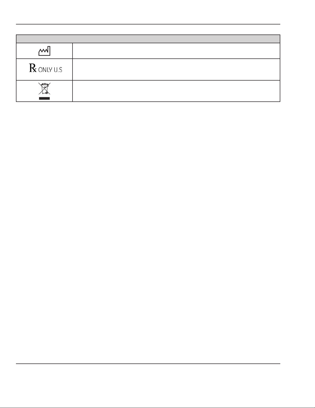
Equipment Symbols
practitioner.
disposed as unsorted municipal waste and must be collected separately. Please contact the
4 2036947-001 © 2013 by General Electric Company. All rights reserved.
Page 23

Important Safety Information
The service information is important for the safety of both the patient and operator and also serves to enhance
equipment reliability.
WARNING:
Before servicing the CorometricsTM 250cx Series monitor, read through this entire manual. As with all
medical equipment, attempting to use this device without a thorough understanding of its operation
may result in patient or user injury. This device should be serviced only by authorized service
personnel. Additional precautions specic to certain procedures are found in the text of this manual.
The information contained in this service manual pertains only to those models of products which are
marketed by GE Healthcare as of the eective date of this manual or the latest revision thereof. This service
manual was prepared for exclusive use by GE Healthcare service personnel in light of their training and
experience as well as the availability to them of parts, proper tools, and test equipment. Consequently, GE
Healthcare provides this service manual to its customers purely as a business convenience and for the
customer’s general information only without warranty of the results with respect to any application of such
information.
Furthermore, because of the wide variety of circumstances under which maintenance and repair activities
may be performed and the unique nature of each individual’s own experience, capacity, and qualications,
the fact that a customer has received such information from GE Healthcare does not imply in any way that
GE Healthcare deems said individual to be qualied to perform any such maintenance or repair service.
Moreover, it should not be assumed that every acceptable test and safety procedure or method, precaution,
tool, equipment, or device is referred to within, or that abnormal or unusual circumstances may not warrant or
suggest dierent or additional procedures or requirements. This manual is subject to periodic review, update,
and revision. Customers are cautioned to obtain and consult the latest revision before undertaking any service
of the equipment.
WARNING:
The user or service sta should dispose of all the waste properly as per federal, state, and local
waste disposal regulations. Improper disposal could result in personal injury and environmental
impact
Do not use malfunctioning equipment. If the system is under warranty, contact GE technical support at the
number on the back of the manual PRIOR to performing any repairs on the system.
© 2013 by General Electric Company. All rights reserved. 2036947-001 5
Page 24
Important Saftey Information
Warnings, Cautions and Notes
WARNING:
ACCIDENTAL SPILLS: In the event that uids are accidentally spilled on the monitor, take the monitor
out of operation and inspect for damage.
WARNING:
APPLICATION: This monitor is not designed for direct cardiac connection.
WARNING:
CONDUCTIVE CONNECTIONS: Avoid making any conductive connections to applied parts (patient
connection) which are likely to degrade safety.
WARNING:
CONDUCTIVE PARTS: Ensure that the conductive parts of the lead electrodes and associated
connectors do not contact other conductive parts including earth.
WARNING:
CONNECTIONS: The correct way to connect a patient to the monitor is to plug the electrode leads
into the patient cable which in turn connects to the monitor. The monitor is connected to the wall
socket by the power cord. Do not plug the electrode leads into the power cord, a wall socket, or an
extension cord.
WARNING:
DEFIBRILLATION: During debrillation, all personnel must avoid contact with the patient and monitor
to avoid a dangerous shock hazard. In addition, proper placement of the paddles in relation to the
electrodes is required to minimize harm to the patient.
WARNING:
DEFIBRILLATION PROTECTION: When used with the GE-recommended accessories, the monitor is
protected against the eects of debrillator discharge. If monitoring is disrupted by the debrillation,
the monitor will recover.
WARNING:
ELECTRICAL SHOCK: To avoid electrical shock hazard, do not operate the monitor with the top cover
removed.
WARNING:
ELECTROMAGNETIC INTERFERENCE: Strong electromagnetic elds may interfere with monitor
operation. Interference prevents the clear reception of signals by the monitor. If the hospital is close
to a strong transmitter such as TV, AM or FM radio, police or re stations, a HAM radio operator, an
airport, or cellular phone, their signals could be picked up as monitor signals. If you feel interference
is aecting the monitor, contact your service representative to check the monitor in your
environment. Refer to Electromagnetic Interference section for additional information.
WARNING:
ELECTROSURGERY: The monitor is not designed for use with high-frequency surgical devices. In
addition, measurements may be aected in the presence of strong electromagnetic sources such as
electrosurgery equipment.
6 2036947-001 © 2013 by General Electric Company. All rights reserved.
Page 25
Important Saftey Information
WARNING:
EXPLOSION HAZARD: Do not use this equipment in the presence of ammable anesthetics or inside
an oxygen tent.
WARNING:
GROUNDING: To avoid electrical shock hazard to the patient or the operator, do not defeat the
three-wire grounding feature of the power cord by means of adaptors, plug modications, or other
methods.
WARNING:
INOPERABLE MECG: The MECG trace is not visible during a LEADS OFF condition or an overload
(saturation) of the frontend amplier during dierential input voltage of more than ±300mV.
WARNING:
INSTRUCTIONS: For continued and safe use of this equipment, it is necessary to follow all listed
instructions. However, the instructions provided in this manual in no way supersede established
medical procedures concerning patient care. The monitor does not replace observation and
evaluation of the patient, at regular intervals, by a qualied care provider who will make diagnoses
and decide on treatments and interventions
WARNING:
INTERFACING OTHER EQUIPMENT: Monitoring equipment must be interfaced with other types
of medical equipment by qualied biomedical engineering personnel. Consult manufacturers’
specications to maintain safe operation.
WARNING:
LEAKAGE CURRENT TEST: The interconnection of auxiliary equipment with this device may increase
the total leakage current. When interfacing with other equipment, a test for leakage current
must be performed by qualied biomedical engineering personnel before using with patients.
Serious injury or death could result if the leakage current exceeds applicable standards. The use
of accessory equipment not complying with the equivalent safety requirements of this equipment
may lead to a reduced level of safety of the resulting system. Consideration relating to the choice
shall include: use of the accessory in the patient vicinity; and evidence that the safety certication
of the accessory has been performed in accordance with the appropriate EN60601.1 harmonized
national standard.
WARNING:
LINE ISOLATION MONITOR TRANSIENTS: Line isolation monitor transients may resemble actual
cardiac waveforms, and thus cause incorrect heart rate determinations and alarm activation (or
inhibition).
WARNING:
MRI USE: Do not use the electrodes during MRI scanning. Conducted current could potentially cause
burns.
WARNING:
PATIENT CABLES AND LEADWIRES: Do not use patient cables and electrode leads that permit direct
connection to electrical sources. Use only “safety” cables and leadwires. Use of non-safety patient
cables and leadwires creates risk of inappropriate electrical connection which may cause patient
shock or death.
© 2013 by General Electric Company. All rights reserved. 2036947-001 7
Page 26
Important Saftey Information
WARNING:
PACEMAKER PATIENTS: Rate meters may continue to count the pacemaker rate during occurrences
of cardiac arrest or some arrhythmias. Do not rely entirely upon rate meter alarms. Keep
pacemaker patients under close surveillance. For disclosure of the pacemaker pulse rejection
capability of the monitor, refer to Appendix A.
WARNING:
RF INTERFACE: Known RF sources, such as cell phones, radio or TV stations, and two-way radios,
may cause unexpected or adverse operation of this device.
WARNING:
SIMULTANEOUS DEVICES: Do not simultaneously connect more than one device that uses electrodes
to detect ECG and/or respiration to the same patient. Use of more than one device in this manner
may cause improper operation of one or more of the devices.
WARNING:
STRANGULATION: Make sure all patient cables, leadwires, and tubing are positioned away from the
patient’s head to minimize the risk of accidental strangulation.
WARNING:
WATER BIRTHS: Do not use the monitor to directly monitor patients during water births, in whirlpool
or submersion water baths, during showers, or in any other situation where the mother is immersed
in water. Doing so may result in electrical shock hazard.
WARNING:
EXTERNAL VGA CONNECTIONS: Connect only to GE-recommended display. ONLY remove cover plate
if external display is used.
WARNING:
TELEMETRY CONNECTIONS: Connect only to GE-recommended telemetry system. Contact your GE
service representative for more information.
WARNING:
COLOR DISPLAY: Certain colors may have limited visibility at a distance. Color-blind individuals may
experience this more often.
WARNING:
EXERGEN® TAT-5000™: Cable assembly 2036641-001, 2036641-002, 2036641-003, and 2036641-
004 cannot be eld serviced. Do NOT attempt any repairs to this assembly. This assembly must be
returned to the factory for any repairs. This assembly, as shipped, is important to patient safety.
WARNING:
DISPOSAL: This product consists of devices that may contain mercury, which must be recycled or
disposed of in accordance with local, state, or country laws. (Within this system, the backlight lamps
in the monitor contain mercury).
CAUTION:
ANNUAL SERVICING: For continued safety and performance of the monitor, verify the calibration,
accuracy, and electrical safety of the monitor annually. Contact your GE service representative.
8 2036947-001 © 2013 by General Electric Company. All rights reserved.
Page 27

Important Saftey Information
CAUTION:
DAILY TESTING: It is essential that the monitor and accessories be inspected every day. It is
recommended practice to initiate the monitor’s selftest feature at the beginning of each monitoring
session.
CAUTION:
ENVIRONMENT: The performance of the monitor has not been tested in certain areas, such as x-ray
and imaging suites. The monitor is not recommended for use in these environments.
CAUTION:
EQUIPMENT CONFIGURATION: The equipment or system should not be used adjacent to, or stacked
with, other equipment. If adjacent or stacked use is necessary, the equipment or system should be
tested to verify normal operation in the conguration in which it is being used.
CAUTION:
PERFORMANCE: Report all problems experienced with the monitor. If the monitor is not working
properly, contact your service representative for service. The monitor should not be used if it is not
working properly.
CAUTION:
PINCHING: Keep ngers clear of the paper roller because the roller could pinch your ngers.
CAUTION:
STATIC ELECTRICITY: This assembly is extremely static sensitive and should be handled using
electrostatic discharge precautions.
CAUTION:
TRAPPING: Keep hands, hair, jewelry, and loose clothing away from the paper roller because the
roller could trap these items.
CAUTION:
TRIPPING: Arrange monitoring equipment so that cords and cables do not present a tripping hazard.
Electromagnetic Interference
This device has been tested and found to comply with the limits for medical devices to the IEC 60601-1-2:
2007, EN60601-1-2:2007, Medical Device Directive 93/42/EEC. These limits are designed to provide reasonable
protection against harmful interference in a typical medical installation.
However, because of the proliferation of radio-frequency transmitting equipment and other sources of
electrical noise in the health-care and home environments (for example, cellular phones, mobile two-way
radios, electrical appliances), it is possible that high levels of such interference due to close proximity or
strength of a source, may result in disruption of performance of this device.
Refer to the Electromagnetic Immunity information in this product’s service manual for EN 60601-1-2 (2007)
Edition 3 compliance information and safety information for this product.
This equipment generates, uses, and can radiate radio frequency energy and, if not installed and used
in accordance with these instructions, may cause harmful interference with other devices in the vicinity.
Disruption or interference may be evidenced in the form of erratic readings, cessation of operation, or incorrect
© 2013 by General Electric Company. All rights reserved. 2036947-001 9
Page 28

Important Saftey Information
functioning. If this occurs, the site of use should be surveyed to determine the source of this disruption, and
actions taken to eliminate the source.
The user is encouraged to try to correct the interference by one or more of the following measures:
• Turn equipment in the vicinity o and on to isolate the oending equipment.
• Reorient or relocate the other receiving device.
• Increase the separation between the interfering equipment and this equipment.
• If assistance is required, contact your GE service representative.
10 2036947-001 © 2013 by General Electric Company. All rights reserved.
Page 29

Chapter 1: System Description
1.1 System Overview
The CorometricsTM 250cx Series monitor is a medical device for monitoring maternal/fetal parameters (Fetal
Heart Rate, Uterine Activity, Maternal Non-Invasive Blood Pressure, Maternal Pulse Oximetry, and Maternal/
Fetal ECG) in labor and delivery (antepartum, intrapartum, and postpartum care). The monitor is equipped
with an LCD display, which provides simultaneous display of fetal and maternal parameters plus the maternal
waveforms, and a recorder, which prints continuous trends and alphanumeric data on one strip chart. The
system is compatible with Centricity® Perinatal Clinical Information Systems and other information systems to
streamline capture and archiving of patient data.
The CorometricsTM 250cx Series monitors are oered in two models:
1. Maternal/Fetal monitor (CorometricsTM 259cx): This model supports two Fetal Heart Rate (FHR) channels,
Uterine Activity (TOCO or IUP), Maternal Non-Invasive Blood Pressure (NIBP), Maternal Pulse Oximetry
(MSpO2), Fetal ECG (FECG), and Maternal ECG (MECG).
2. Fetal monitor (CorometricsTM 256cx): This model supports two Fetal Heart Rate (FHR) channels, Uterine
Activity (TOCO or IUP), and Fetal ECG (FECG).
Table 1-1: Monitor Models and Features
Monitor Model Features
Maternal/Fetal monitor (CorometricsTM 259cx)
Fetal Only monitor (CorometricsTM 256cx) US, US2, TOCO, IUP, FECG
Below optional components are also available to order:
A. Software Upgrade CD: The CD can be purchased to upgrade the monitor software to the latest version
using the RS-232 serial port of the monitor.
B. Spectra Alerts option: Each monitor unit can be upgraded to include Spectra Alerts option. This feature
analyzes heart rate and uterine activity data to detect certain abnormal trends and alert the clinician.
C. Fetal Movement Detection option: Each monitor unit can be software upgraded to include the Fetal
Movement Detection (FMD) software option. This feature is designed to detect gross fetal body
movements and body movements with associated limb movement.
US, US2, TOCO, IUP, FECG, MECG, NIBP, MSpO
2
© 2013 by General Electric Company. All rights reserved. 2036947-001 11
Page 30
Chapter 1: System Description
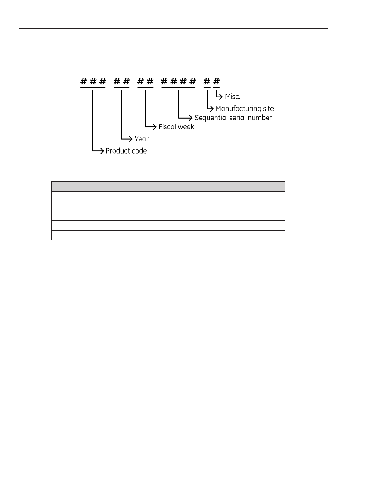
Each monitor unit has its unique 13-Digit product serial number which contains embedded information about
the unit manufacturing date and site (See Figure 1-1).
Product Code Description
SDJ 259CX-A (Nellcor, India Build)
SDK 259CX-B (Nellcor, US Build)
SDL 259CX-C (Masimo, India Build)
SDM 259CX-D (Masimo, US Build)
SDR 259CX-X (India Build)
Figure 1-1 Global Serial Number Format (13-Digit)
NOTE: For the refurbished (Gold Seal) CorometricsTM 259cx units, the unit serial number ends with letter “R” and
the the serial number label of the unit includes the text “259CX REMANUFACTURED”.
12 2036947-001 © 2013 by General Electric Company. All rights reserved.
Page 31

1.2 Front Panel Controls, Indicators, and Connectors
Chapter 1: System Description
Figure 1-2 Front Panel View
A. Display: The monitor display is divided into several sections. The content and layout of the display can
change, depending on which functions are installed in the monitor and the modes of operation in use.
B. Trim Knob Control: Operation of the monitor is controlled by using the front panel buttons in
conjunction with the Trim Knob Control. This control selects softkeys on the display and positions a
cursor within a setup screen. Rotate the Trim Knob Control left or right to highlight items on the screen
with a bar cursor. After highlighting the desired item, press the Trim Knob Control to make the selection.
In summary, rotate to move cursor and press to select an item.
C. NIBP Start/Stop Button: This button starts and stops both manual and automatic blood pressure
determinations. Pressing and holding this button provides a “shortcut” for changing the interval time of
the NIBP cycle in the automatic mode.
D. Test Button: Pressing this button starts or stops a monitor self-test routine.
E. Mark [Oset] Button: The Mark [Oset] button is a multi-function button:
• Mark: Pressing this button prints an event mark ( ) on the bottom two lines of the top grid on the
strip chart paper.
• Oset: When the Heart Rate Oset mode is enabled, pressing and holding this button shifts the
secondary FHR trend +20 bpm for visibility purposes.
© 2013 by General Electric Company. All rights reserved. 2036947-001 13
Page 32

Chapter 1: System Description
F. UA Reference Button: This button sets a baseline for uterine activity pressure monitoring.
G. Paper Advance Button: Pressing this button advances the strip chart paper at a rate of 40 cm/min for
as long as the button is held down.
H. Record Button: This button selects one of three recorder states: on, maternal-only mode, or o.
I. Power Indicator: This LED indicator illuminates in green when the monitor is turned on.
J. Recorder Indicator: This LED indicator shows the status of the recorder as per below table:
Recorder Indicator Status What It Means
On Recorder is on.
O Recorder is o.
Three short ashes every 5 seconds Recorder is in maternal-only mode.
Flashes on and o Error condition
K. Light Button: This button illuminates the strip chart paper for better visibility.
L. Record Door Latch: This latch opens the strip chart recorder door for adding, removing, or adjusting
the paper.
M. Power Switch: Moving this switch to the ON position (I) turns on the monitor; moving the switch to the
OFF position (O) turns o the monitor.
N. Strip Chart Recorder: The recorder prints annotations and trends on the strip chart paper. Two paper
styles are available.
O. Maternal NIBP Connector: This connector is for attaching the blood pressure cu.
P. Maternal SpO2 Connector: Connect a 250cx Series MSpO2 intermediate cable to this connector. Use
only Nellcor Maternal Oxygen Saturation Sensors if Nellcor technology is installed in your monitor, or
Masimo Sensors if Masimo technology is installed in your monitor.
Q. FECG/MECG Connector: Connect an FECG cable/legplate or MECG cable plug to this connector. Cables
with rectangular plugs connect directly to the FECG/MECG connector. Cables with round plugs require
an FECG/MECG adapter. This adapter is used for dual ECG monitoring too. The adapter branches into
two cables, each with a round connector at the end: one branch is labeled MECG; the other branch is
labeled FECG.
R. UA Connector: Connect a TOCO transducer or IUPC to this connector.
S. US2 Connector: Connect the secondary ultrasound transducer plug to this connector.
T. US Connector: Connect the primary ultrasound transducer plug to this connector.
14 2036947-001 © 2013 by General Electric Company. All rights reserved.
Page 33

Chapter 1: System Description
U. Volume Button (FHR2 Decrease): This button is used to decrease the fetal heart rate (FHR2) sound
volume of the second ultrasound channel (US2). Volume settings have no eect on the processing used
to determine heart rate. The Volume buttons work in conjunction with the volume control settings on
the US/US2 Setup screen and on the FECG Setup screen.
V. Volume Button (FHR2 Increase): This button is used to increase the fetal heart rate (FHR2) sound
volume of the second ultrasound channel (US2). Volume settings have no eect on the processing used
to determine heart rate. The Volume buttons work in conjunction with the volume control settings on
the US/US2 Setup screen and on the FECG Setup screen.
W. Volume Button (FHR1 Decrease): This button is used to decrease the fetal heart rate (FHR1) sound
volume of the primary ultrasound channel (US). Volume settings have no eect on the processing used
to determine heart rate. The Volume buttons work in conjunction with the volume control settings on
the US/US2 Setup screen and on the FECG Setup screen.
X. Volume Button (FHR1 Increase): This button is used to increase the fetal heart rate (FHR1) sound
volume of the primary ultrasound channel (US). Volume settings have no eect on the processing used
to determine heart rate. The Volume buttons work in conjunction with the volume control settings on
the US/US2 Setup screen and on the FECG Setup screen.
Y. Alarm Silence Button: Pressing this button silences the audible indication of an individual alarm.
1.3 Display Description
Display Example: The graphic in Figure
1-3 gives the following information:
• Blood pressure (NIBP) is not active
as indicated by the absence of
numerics.
• Maternal pulse oximetry (MSpO
is active by presence of pulse
amplitude indicator.
• MECG is selected as the heart rate
source as indicated by the MECG
mode title softkey—rather than
Pulse.
• The MECG waveform is displayed at
25 mm/sec, at a size of 2x, with lead
II selected
• Heartbeat coincidence is enabled
as indicated by the HBC acronym in
the primary labor parameters area.
• All alarms are enabled as indicated
by symbol.
)
2
Figure 1-3 Display Information Example
© 2013 by General Electric Company. All rights reserved. 2036947-001 15
Page 34

Chapter 1: System Description
The monitor LCD display is designed to show the information listed below:
1.3.1 Primary Labor Parameters
These parameters, shown on the upper portion of the screen (See Figure 1-3), include Fetal Heart Rate 1 (FHR1),
Fetal Heart Rate 2 (FHR2), and Uterine Activity (UA). Each parameter can have several modes depending on the
type of its input.
Parameter Parameter Mode
Fetal Heart Rate 1 (FHR1) US, US2, FECG, or INOP
Fetal Heart Rate 2 (FHR2) US, US2, or INOP
Uterine Activity (UA) TOCO, IUP, or INOP
For FHR1 and FHR2 parameters, the FHR value is shown in beats per minute and the FHR mode is displayed
above the FHR value. For UA parameter, the UA value is shown in a user-selectable unit (mmHg or kPa) and the
UA mode is displayed above the UA value.
1.3.2 Additional Parameters
These parameters, shown on the middle portion of the screen (See Figure 1-3) are available in Maternal/
Fetal monitor models only. The parameters include Maternal Blood Pressure, Maternal Heart/Pulse Rate, and
Maternal SpO2. Each parameter can have several modes depending on the type of its input.
Parameter Parameter Mode
Maternal Blood Pressure NIBP
Maternal Heart/Pulse Rate MECG, Pulse, or INOP
Maternal SpO
2
MSpO
2
1.3.3 Waveform
The monitor display can show Fetal ECG Waveform, Maternal ECG Waveform, or Maternal SpO2 Pulsatile
Waveform on the bottom portion of the screen (See Figure 1-3). So the waveform can have several modes:
FECG, MECG, MSpO2, or O.
1.3.4 Time
The display also shows Current Time, [Label] Frozen Message and Time of Activation (See Figure 1-3).
1.3.5 Softkeys
The display includes several system conguration softkey controls (See Figure 1-4). A softkey is an area on the
screen that can be selected with the Trim Knob Control. When the softkey is activated by pressing the Trim
Knob Control, it may cycle through available settings or it may display a setup screen.
16 2036947-001 © 2013 by General Electric Company. All rights reserved.
Page 35

Description of softkeys:
Chapter 1: System Description
Figure 1-4 Display Softkeys
A. Mode Title Softkeys: Selects US, US2, FECG, NIBP, MHR/P, or MSpO2 Setup screens.
B. ECG Scale Softkey: Selects 0.25x, 0.5x, 1x, 2x, 4x, or Auto.
C. MECG Lead Softkey: Selects Lead I, II, or III.
D. VSHX Softkey: Displays maternal Vital Signs History screen (See Figure 1-5).
E. Setup Softkey: Displays General Setup screen.
NOTE: For detailed information on setup screens, refer to Appendix E.
F. Alarms Softkey: Displays Master Alarm Setup screen.
G. Freeze Softkey: Freezes waveform for analysis; unfreezes waveform to return to real-time display.
H. Print Softkey: Prints 6-second snapshot of frozen waveform, real-time waveform, or maternal vital
signs history.
I. Waveform Softkey: Selects FECG, MECG, MSpO2, or O.
© 2013 by General Electric Company. All rights reserved. 2036947-001 17
Page 36

Chapter 1: System Description
Figure 1-5 Maternal Vital Signs History Screen Softkeys
A. Print Softkey: Prints one page (screen) of the table.
B. PrintAll Softkey: Prints all pages (screens).
C. View Softkey: Scrolls through the data Counterclockwise for newest data or Clockwise for oldest data
D. Exit Softkey: Returns to the previous screen.
18 2036947-001 © 2013 by General Electric Company. All rights reserved.
Page 37

1.4 Rear Panel Descriptions
CAUTION:
The maximum nondestructive voltage that may be applied to the rear panel connectors is 0 volts.
Do not connect cables to these connectors without ensuring the connectors comply with leakagecurrent requirements of one of the following applicable standards: UL 60601-1, CSA C22.2 No. 601.1
or IEC/EN 60601-1.
Chapter 1: System Description
Figure 1-6 Rear Panel View
A. Vent: Provides ventilation for the monitor internal circuitry.
B. Telemetry Connector (J101): Connector for CorometricsTM 340 or Mini Telemetry system interface.
C. Data Entry Connector (J103): This connector is specically designed for connecting to the legacy
CorometricsTM 2116B Data-Entry/Clinical-Notes Keyboard.
D. Nurse Call System (J104): This connector attaches to a standard Nurse Call System. The connector’s
maximum output is 50 Vdc at 100 mA and the maximum on resistance is 0.5 Ω. When connected to
a Nurse Call System, the monitor will activate the system each time a Spectra Alert is issued. This
interface simulates pressing the button on a bedside Nurse Call System allowing nurses to respond to
© 2013 by General Electric Company. All rights reserved. 2036947-001 19
Page 38

Chapter 1: System Description
patient needs quickly and eciently. Although the J104 Nurse Call connector is physically present on
the optional communications package, this connector is only supported as part of the Spectra Alerts
option. The Spectra Alerts or Fetal Alarms can be enabled/disabled in Install Options Screen 2 in service
mode screens (Refer to Fetal Alerts/Alarms description under See Figure E-3).
E. Central Systems Connector (J102): This Centronics-type connector is designed for interfacing to a
legacy Corometrics Spectra 400 Central Surveillance and Alert System or other compatible analog
central information system. This connector is often referred to as the Analog Interface Connector.
F. External VGA Connector (J112): This 15-pin sub-D connector is for interfacing to an external VGA
display. Use of GE-recommended external display will allow monitor front panel display video to be
replicated remotely.
G. Speaker: The rear panel speaker emits audible tones for heart rates, MSpO2 pulse with %O2-dependent
pitch, and alarms. It also provides the sound for the song player feature.
H. Communication Connectors (J109, J110, J111): These RJ-11 connectors provide three RS-232C serial
interfaces that allow connecting the monitor unit to the following peripheral devices:
• Nellcor Puritan Bennett (NPB) N-200 Maternal Oxygen Saturation Monitor (J109 and J111 only)
• DINAMAP® PRO Series 100-400 Monitors
• DINAMAP® ProCare, V100 Monitors
• Quantitative Sentinel/Perinatal System (any RS-232C connector)
Upon shipping from the factory, all three ports are congured as follows:
• Communication Mode = 1371/Notes
• baudrate (bps) = 2400
At the above settings, connectors J109 and J111 are ready for connection to an NPB Model N-200.
Connector J110 does not support a connection to NPB monitors. Therefore, this connector will have to
be congured to communicate to the peripheral device.
Pin Number Signal Name
1 RTS
2 RXD
3 GND
4 GND
5 TXD
6 CTS
Figure 1-7 J109, J110, J111 Pin Numbers and Names
I. ECG Out Connector: This 3-conductor stereo phone jack allows recording of FECG or MECG trends on
an external recorder. ECG signals are output at +80 dB with a bandwidth of 1.0 to 100 Hz. MECG signals
20 2036947-001 © 2013 by General Electric Company. All rights reserved.
Page 39

Chapter 1: System Description
are output at +60 dB with a bandwidth of 0.5 to 40 Hz. The output level from this port is 10 V/mV for
FECG and 1 V/mV for MECG.
J. Fetal Acoustic Stimulator Connector: Connector for CorometricsTM 146 Fetal Acoustic Stimulator
(FAST). A musical note symbol ( )prints on the strip chart paper each time CorometricsTM 146 is used.
K. Remote Event Marker Connector: This connector is for connection to an optional Corometrics Remote
Event Marker which is used to annotate the strip chart paper in the recorder with a mark. The mark can
be congured as one of the below:
• The event symbol ( ) to record an “event”
• The fetal movement symbol ( ) to record the perceived fetal movement occurrence by the
mother. This is the default setting.
L. Equipotential Lug: A binding post terminal is directly connected to the chassis for use as an
equipotential connection.
M. AC Voltage Selection Switch: This switch is intended for authorized service personnel to select the
proper voltage for the AC input:
• 120: Lets the unit accept an AC input in the range of 100–120 VAC.
• 240: Lets the unit accept an AC input in the range of 220–240 VAC.
N. Power Inlet Module: AC line power cord connector.
1.5 Peripherals Description
This section provides information about the peripheral systems that can be attached to the CorometricsTM
250cx Series monitors.
1.5.1 CorometricsTM 340 Telemetry and Mini Telemetry
CorometricsTM 250cx Series monitor can be interfaced to a CorometricsTM 340 Telemetry system (receiver) or a
Mini Telemetry system (receiver) thought J101 connector on the rear side of the monitor. Upon connecting the
monitor to either telemetry systems, a “telemetry connected” symbol ( ) will appear beneath FHR1 eld on
the display when both the telemetry system and the monitor are turned on and the telemetry receiver detects
an active FECG, MECG, US, TOCO, or IUP mode from its corresponding transmitter. The “telemetry connected”
symbol will also be printed on the bottom line of the top grid of the strip chart paper upon commencement of
the telemetry monitoring and every 30 minutes along with the modes.
NOTE: When any telemetry mode (US, FECG, MECG, TOCO, or IUP) is detected, all equivalent front panel modes
(US, US2, FECG, MECG, TOCO, or IUP) are ignored. You cannot “mix and match” telemetry and monitor
modes.
© 2013 by General Electric Company. All rights reserved. 2036947-001 21
Page 40

Chapter 1: System Description
A “telemetry disconnected” symbol ( ) will be printed on the strip chart paper if the telemetry receiver is
unplugged from the monitor, or the telemetry system (transmitter or receiver) is turned o, or the telemetry
receiver does not detect any active mode information from its corresponding transmitter.
1.5.2 Quantitative Sentinel/Perinatal System
Through this interface, the monitor outputs MHR data, FHR data, and UA data to a central information such as
a Quantitative Sentinel/Perinatal System. Annotations made at the central station can be optionally printed on
the strip chart paper of the monitor as summarized below (if the central station has the capability to send the
command):
• Each message is preceded by a computer icon ( ).
• Messages are restricted to a maximum length of 50 characters.
• Lower-case letters are converted to upper-case letters.
• Non-standard characters are replaced with spaces.
The monitor can be congured with the remote annotation capability enabled (1371/Notes mode) or disabled
(1371 mode). Set the communication Mode to 1371 or 1371/Notes and the Baud rate to the specied value by
the manufacturer in the Communication Setup screen (See Figure E-4).
To connect a central information system:
1. Obtain an appropriate interface cable: connect one end to an available RS-232C connector (J109, J110, or
J111) on the monitor unit. Connect the other end to the wall plate wired to the central information system.
For a Quantitative Sentinel/Perinatal System: the interface cable is catalog number (REF) 1558AAO (10’) or
1558BAO (20’); the corresponding wall plate connector is labeled RS-232 COMMUNICATIONS.
2. Access the Communications Setup service mode screen and set the baudrate and mode for the appropriate
port to 1200 bps and either the 1371 or 1371/Notes mode, respectively. Then exit the service mode
screens.
1.5.3 Exergen® TAT-5000
TM
Exergen® TAT-5000™ provides maternal temperature as a printout and vital signs history. Set the
communication Mode to Exergen and the Baud rate to 4800 in the Communication Setup screen (See Figure
E-4).
1.5.4 DINAMAP® Models PRO Series 100-400 and ProCare
All of the DINAMAP® Models PRO Series 100-400 ProCare, and V100 monitors can be interfaced to
CorometricsTM 250cx Series monitors using an ILC-1926 interface, one DINAMAP V-Link cable assembly (Part
number: 683235), and one CorometricsTM DINAMAP serial cable (Part number: 2007234-001) to provide a
printout of the NIBP parameter on the strip chart paper. Set the communication Mode to Critikon and the Baud
rate to the specied value by the manufacturer in the Communication Setup screen (See Figure E-4).
22 2036947-001 © 2013 by General Electric Company. All rights reserved.
Page 41

Chapter 1: System Description
1.6 Theory of Operation
The CorometricsTM 250cx Series system is made up of front-end and back-end sections, system power supply,
and recorder module. The Main board forms the heart of the monitor control functions. The Main board along
with the communications board forms the back-end section of the monitor. The front-end section boards are
housed in the sealed front-end card cage and consist of FECG/UA board, MECG board, Dual ultrasound board,
SpO2 carrier board, MSpO2 connector board, and the Frond-end motherboard. The DSP/Display board is the
bridge between the front-end and back-end sections. The recorder assembly houses the recorder board.
Figure 1-8 depicts the system block diagram of the monitor unit and illustrates all the boards, external parts,
their connections (cable or direct plug-in), isolated areas, and the functionalities of the boards.
Upon power-up, the CorometricsTM 250cx Series monitor automatically performs a number of tests to verify
the integrity of the system memory, processor, and voltage levels before allowing the monitor to enter the
normal operational mode. The pulse oximetry module is also tested (and automatically calibrated) upon
power up or whenever the module is reset. After setting the Power switch to the on (I) position, the tests run for
approximately 2 seconds. If all tests pass, the monitor enters the normal operational mode.
1.6.1 Digital System Processor (DSP) / Display Board
The DSP/Display board consists of two independent functioning sub-circuits: the DSP sub-circuit and the
Display interface sub-circuit.
The DSP circuitry processes analog and digital data from the front-end modules and interfaces to the main
processor. The ECG and ultrasound analog information is processed and heart rates are output to the Main
board via a shared memory. Digital pressure information is received, processed, and also sent to the shared
memory.
The Display sub-circuit, consisting mainly of a shared memory and timing generator, provides the interface
between the LCD and the main processor. Circuitry for the main processor to adjust the brightness of the LCD
is provided through a DC-to-AC inverter. RS-232 communications between the Main board and the UI keypad
board are routed through the DSP board.
© 2013 by General Electric Company. All rights reserved. 2036947-001 23
Page 42

Chapter 1: System Description
Figure 1-8 System Block Diagram
24 2036947-001 © 2013 by General Electric Company. All rights reserved.
Page 43

Chapter 1: System Description
1.6.2 Main Board
The Main board makes up the central processing unit for the monitor unit. The Main board accepts
simultaneously processed parameters directly from four separate modules. The minimum conguration
monitor has only the DSP board as an input module. Heart rate (ultrasound and or FECG), uterine activity data,
mode information, and FMD data ow from the DSP board to the Main board via DSP board FPGA shared
memory. Maternal and fetal Oximetry makes up the second and third modules. Information from these devices
is passed to the Main board via RS-232 ports. The Main board communicates with the front panel UI keypad
board using RS-232 interface, which is routed through the DSP board. The Main board also provides a master
reset for the UI keypad board. The Main board holds the NIBP control circuitry (minus pump and valves) and
communicates to it using a CMOS interface. The Main board connects to the Pneumatics board which holds
the NIBP pump, valves, and lter. The Main board contains three external RS232 data ports for various external
devices and setup/code update functions. The Main board receives data from the rear panel options board to
allow the added Communication features. The Main board formats all the data and interfaces to the recorder
board. The Main board also controls all of the audio functions including generated tones to passing ultrasound
audio from the ultrasound board.
The Main board contains one dip switch pack (SW1) that determines some of the monitor congurations (See
Table 1-2). The current settings of the SW1 switches can be checked without removing the unit top cover
by accessing the Diagnostic Control screen (See section E.5), which displays the status of switches from left
(i.e. switch number 8) to right (i.e. switch number 1). A “1” status means the corresponding switch is o and
a “0” status means the corresponding switch is on. To change the switch settings, the unit top cover shall be
removed to access the SW1 swtich. Below is an example of the SW1 switch status:
Table 1-2: SW1 Switch Settings
Switch Number Switch Name & Description Settings
1 Factory Test: For factory use only O = Enabled
2
J102 Output Levels: Select between J102 outputs compatible
with HP or Corometrics
TM
O = HP
On = Corometrics
TM
4 NIBP Option: Enable/disable the maternal NIBP. O = Enabled
5
MSpO2 Option: Select between the MSpO
options.
2
6
Nellcor: 5=O, 6=O
Masimo: 5=On, 6=O
No MSpO2: 5=On, 6=On
7 Inactive Inactive
8 MECG Option: Enable/disable the MECG option. O = Enabled
© 2013 by General Electric Company. All rights reserved. 2036947-001 25
Page 44

Chapter 1: System Description
1.6.3 User-Interface Keypad & Volume/Alarm Keypad Boards
The user-interface keypad board is responsible for two functions, a) input controls, and b) the recorder chart
light feature. The board contains most of the front panel buttons (except for the volume and alarm cancel
buttons) and receives input from the Trim Knob Control. The keypad is of the elastomeric type and utilizes
backlight LEDs to light each key. The board also receives the volume/alarm keypad board inputs through an
external cable, processes all key closures, and communicates the key statuses to the main processor. The
Main board receives data from the main processor (routed through DSP/Display board) and controls the
Recorder Indicator LED. The volume/alarm keypad board contains the volume and alarm key buttons and
sends the button statuses to the user-interface keypad board. The volume/alarm keypad board is also of the
elastomeric type and has backlight LEDs for each key. The user-interface keypad board interface with the Main
board is through an RS-232 interface.
1.6.4 Video Decoder Board
The video decoder board interfaces between the DSP/Display board and the LCD panel. The video decoder
board performs conversion of 4-bit color information from the FPGA output to the 18-bit color required by the
LCD panel. This provides a 16-color palette. The translation is accomplished in the FPGA on the video decoder
board. This board receives high-speed video from the DSP/Display board.
1.6.5 Recorder Board
The recorder board is responsible for driving the recorder motor and the recorder print head device along with
providing the main system board with paper out/low/misload status. To drive the motor it receives pulses from
the main system board and provides the proper drive circuitry to drive the stepper motor 4 phase windings.
To drive the print head an adjustable power supply is provided which is set to the print head specications
(each print head is unique). Data to be printed and control information is received from the main system board,
buered and presented to the print head. Sensors from the recorder assembly to detect paper low/out/misload
are received and translated to digital status lines to be sent to the main system board.
1.6.6 Communications Board
The communications board contains three basic interfaces. It supports the analog interface (J102) to the
legacy Spectra 400 surveillance system as well as other manufacturer’s centrals, a 2116 external keyboard
interface for strip chart annotation, and an analog telemetry interface to the CorometricTM 340 or Mini
Telemetry system. The communications board communicates to the system by directly plugging into the main
system board. Digital data from the keypad interface and telemetry (modes only) is transferred through a data
bus and analog signals (MECG, FECG, Ultrasound, TOCO) from the telemetry are separately routed through the
Main board to the DSP for processing similarly to the existing front panel patient data.
1.6.7 MSpO2 Connector Board
The MSpO2 connector board receives the universal SpO2 patient cables on the front bezel of the monitor unit
and transfers the analog signals on to the internal SpO2 cable that in turn connects to the SpO2 Carrier board.
26 2036947-001 © 2013 by General Electric Company. All rights reserved.
Page 45

Chapter 1: System Description
All the signals entering this board are patient isolated and signals leaving this board though the MSpO2 cable
are also isolated.
1.6.8 MSpO2 Carrier Board
The SpO2 carrier board holds the SpO2 module. It receives MSpO2 patient cable connections from the universal
front-end connector board and internal cable on its isolated side and routes them to the connected NELL3-S,
Nellcor MP-506 or NELL-3, or Masimo MS-11 or MS-2011 modules. It supplies isolated power to the SpO2
modules and transfers the isolated data generated by the modules using opto-couplers to the front-end
motherboard on to the monitor system for processing. The monitor system is able to reset the maternal and
the SpO2 modules using opto-coupled reset lines.
1.6.9 FECG/UA Board
The FECG/UA board is made up of two separate isolated patient front-end sub-circuits: FECG and Uterine
Activity. The FECG sub-circuit converts the low level signals received from the fetus through the spiral electrode
to electrical impulses which are amplied, ltered, and sent across an isolation barrier. The un-isolated FECG
signal then is further amplied and sent o the FECG board, routed by the front-end motherboard to the DSP/
Display board, where it is digitized and processed. Additionally, the FECG mode line (cable plugged in sense line)
from the ECG connector is digitized and sent over the barrier via an opto-coupler where it is routed similarly to
the FECG analog signal.
The Uterine Activity sub-circuit processes the pressure signals from the external TOCO or IUP sensor (use same
inputs), by amplifying and ltering the inputs, and then converts the signals via serial analog to digital (A/D)
converter. The output of the A/D converter is then sent across the isolation barrier, routed through the frontend motherboard through to the DSP/Display board where it is further processed. Two mode lines from the UA
patient connector are also digitized: TOCO present and IUP present (only one cable can be plugged in at a time).
These signals are then sent over the barrier via an opto-coupler where they are routed similarly to the TOCO/
IUP digitized signals.
1.6.10 MECG Board
The MECG board processes the isolated MECG signals present from the ECG front panel connector. The multilead signals rst go through programmable lead switching circuitry controlled by the DSP processor. The MECG
signal is then amplied and ltered and sent across the isolation barrier where it is routed through the frontend motherboard to the DSP/Display board, digitized and processed. The MECG board also contains an ECG
test signal on the isolated side which is used when the monitor front panel test button is depressed. This tests
most of the front-end circuitry paths. The MECG board also contains pacemaker detection circuitry allowing
the monitor to blank out the pulses for proper counting.
1.6.11 Dual Ultrasound Board
The dual ultrasound board generates the ultrasound timing signals to pulse the external patient connected
ultrasound transducer crystals and provides the necessary receive circuitry to detect the reected waveforms.
It does this by rst demodulating the needed signal o of the carrier and ltering the signals which are then
© 2013 by General Electric Company. All rights reserved. 2036947-001 27
Page 46

Chapter 1: System Description
sent through the frontend motherboard to the DSP where they are digitized and processed. No isolation is
present from the patient connector through the ultrasound board as the plastic ultrasound transducer forms
the physical isolation barrier.
1.6.12 Isolated Power Supply Board
The isolated power supply board provides all of the isolated power for the FECG/UA board, MECG board and
the carrier board which in turn feeds the two SpO2 modules (MSpO2). The ultrasound board is not powered from
this board as it is not electrically isolated. The isolated power supply is made up of two isolated sets of supplies.
One supply set is specically for FECG on the FECG/UA board. The other isolated set of supplies powers the
remaining functions including TOCO/IUP (on the FECG/UA board), MECG (MECG board), and the SpO2 Carrier
board (SpO2 modules). The un-isolated power input to this PWA consists of +20 volts routed from the front-end
motherboard through the DSP and Main board and then nally the system power supply.
1.6.13 Front-End Motherboard
The front-end motherboard is a passive inter-connection board which houses all of the front-end parameters
except for NIBP. In addition to the parameters, it holds the isolated power supply. The board routes all of the
isolated and un-isolated signals to and from the DSP/Display board. This includes both analog and digital
parameter inputs and digital control outputs. On the front-end side it interfaces to the pressure channel frontend cable and the FECG front-end cable, which carries all of the FECG signals as well as the MECG mode lines.
The MECG analog signals are routed separately from the front panel to the MECG daughter board. The MSpO2
input signals enter the SpO2 carrier board directly.
1.6.14 Memory Battery
Whenever the monitor is turned o, a battery provides power to the Random Access Memory (RAM) that stores
information such as time, date, default settings, etc. An icon ( ) will appear in the upper right-hand section
of the monitor display in the following circumstance:
A. RAM data corruption: The ( ) icon appears for a short period of time after the system power-up
on the monitor display in data corruption conditions, which makes the monitor revert to the factory
settings. To re-congure the settings, access the setup screens.
B. Bad Battery: The ( ) icon appears steadily after the system power-up on the monitor display when
the RAM battery has reached end-of-life and needs to be replaced.
NOTE: Always set the time and date prior to the initial operation of the monitor after the RAM battery
replacement. Update the settings during the daylight-saving time changes.
28 2036947-001 © 2013 by General Electric Company. All rights reserved.
Page 47

Chapter 2: Installation
This chapter provides information required to install the CorometricsTM 250cx series monitor.
2.1 Time Required for Installation
The average installation time for the CorometricsTM 250cx series monitor is approximately 10 minutes. The
required checkout procedures after installation takes approximately 30 minutes.
2.2 Environmental Requirements
The system shall be installed, serviced, and operated within the environmental conditions described in section
A.1.
2.3 Tool Requirements
None
2.4 Installation Procedure
2.4.1 Strip Chart Recorder Paper Load
CAUTION:
Use GE-approved recorder paper only. Using the wrong paper may damage the recorder print head
and product inferior print quality.
CAUTION:
The monitor recorder shall be loaded with the paper at all times. This reduces particle build-up on
the print head and facilitates opening the recorder door.
© 2013 by General Electric Company. All rights reserved. 2036947-001 29
Page 48

Chapter 2: Installation
To load strip chart recorder paper perform below steps:
1. Press down the latch on the right side of the strip chart recorder door (See Figure 2-1).
2. Fan the pack of Z-fold paper on all sides to loosen any folds and to ensure proper feed of the paper
through the recorder.
3. Hold the package of paper such that the black squares are on the bottom of the pack and the Corometrics
logo and page numbers are on the left side of the pack (See Figure 2-2).
NOTE: The black squares indicate the end of the recorder paper. When the black squares appear, the strip chart
recorder has approximately 20 minutes of paper remaining, when running at a speed of 3 cm/min.
4. Unfold two sheets from the top of the package so that they extend toward you (See Figure 2-3).
5. Place the pack of paper in the drawer so that the pack is in a at position in the recorder (See Figure 2-4).
6. Slowly close the strip chart recorder door, being careful not to skew the paper (“Figure 2-5”).
Figure 2-1 Figure 2-2
Figure 2-3 Figure 2-4
30 2036947-001 © 2013 by General Electric Company. All rights reserved.
Page 49

Chapter 2: Installation
2.4.2 Peripheral Connections
If present, connect the below optional peripherals to the CorometricsTM 250cx series monitor as per the
following instructions:
Remote Event Marker: Plug the marker connector into its corresponding jack on the rear side of the monitor.
Corometric 340 Telemetry / Mini Telemetry system: Plug the interconnect cable (Part number: 1563AAO) into
the Telemetry Connector (J101) on the rear side of the unit (Refer to Corometric 340 Telemetry / Mini Telemetry
service manuals for installation details).
External Video Display: Plug the display cable into the External Display Connector (J112) on the rear side of
the unit.
Quantitative Sentinel / Perinatal System: Plug the interface cable into an available RS-232C connector (J109,
J110 or J111) on the rear side of the unit.
2.4.3 Power Cord Attachment
1. Conrm the monitor power switch is in o (O) position.
2. Connect the power cord to the power connector on the rear panel of the monitor and secure the power
cord with the P Clamp (See Figure 2-6).
3. Verify that the AC voltage selector on the rear panel of the monitor is set to the correct country-specic
voltage (See Figure 2-6).
CAUTION:
Incorrect setting of the AC voltage selector can damage the monitor.
4. Plug the power cord into a power outlet.
2.4.4 System Conguration
1. Turn the monitor on. Conrm that the Power indicator (green light) illuminates, the monitor display is on,
and the monitor generates a series of tones, indicating that the unit has been turned on.
Figure 2-5 Figure 2-6
© 2013 by General Electric Company. All rights reserved. 2036947-001 31
Page 50

Chapter 2: Installation
2. Use the Trim Knob Control to select the Setup softkey to display the General Setup screen and set
the correct date and time (“Figure 2-7”). Set the paper speed in accordance with the hospital or local
requirements.
WARNING:
Incorrect paper speed setting results in inaccurate waveform prints on the strip chart paper.
3. Select the Service softkey on the screen to have the Service Lock screen with 0 0 0 0 access code displayed
(“Figure 2-8”).
4. Use the Trim Knob Control to enter the access code as either the current month or day (MMDD) or day and
month (DDMM), depending on how the monitor is congured. For example, April 23 shall be entered as 0 4 2
3.
NOTE: To gain access to the service screens, the correct date and time must be set on the General Setup
screen.
5. Upon entering the access code, press the Trim Knob Control to access Install Options Screen 1 screen.
(“Figure 2-9”).
6. Use the Trim Knob Control to navigate on the screen and change the factory default settings if necessary
(See Appendix E for conguration setting details). Make sure to set the paper scaling to match with the type
of paper used.
WARNING:
Incorrect paper scaling setting (mismatch between the paper scaling and type of paper used) results
in invalid waveform prints on the strip chart paper.
7. If any peripherals are installed to communicate to the monitor through RS-232C connectors, use the
Trim Knob Control to select the COMM softkey on Install Options Screen 1 to access the Communication
Setup screen (“Figure 2-10”). Use the Trim Knob Control to set the communication baud rates and modes
to be compatible with the external peripheral device and then exit the screen. For more information on
Communication Setup screen elds, refer to section E.4.
NOTE: For Quantitative Sentinel/Perinatal System, set the baud rate and mode for the appropriate port to 1200
bps and either the 1371 or 1371/Notes respectively.
8. Use the Trim Knob Control to select the NextPage softkey to access the Install Options Screen 2 screen and
change the factory default settings if necessary. (See Appendix E for conguration setting details).
9. To store the changed conguration settings as the monitor default settings, use the Trim Knob Control to
select Store Current to Hospital option on the Install Options Screen 2 screen. Conrm the Default Setting
option changes to Hospital (“Figure 2-11”).
WARNING:
When the monitor is turned on or restarted, the conguration settings revert back to the Default
Setting option selected, i.e. Factory or Hospital.
32 2036947-001 © 2013 by General Electric Company. All rights reserved.
Page 51

Chapter 2: Installation
10. Use the Trim Knob Control to select Restart softkey to accept the settings and reboot the unit.
11. Perform the checkout procedures as instructed in chapter 3 before putting the monitor into use.
Figure 2-7
Figure 2-8 Figure 2-9
Figure 2-10 Figure 2-11
© 2013 by General Electric Company. All rights reserved. 2036947-001 33
Page 52

Chapter 2: Installation
34 2036947-001 © 2013 by General Electric Company. All rights reserved.
Page 53

Chapter 3: Maintenance and Checkout
This chapter includes planned maintenance procedures as well as checkout procedures required after
CorometricsTM 250cx series product installation, repair, or maintenance. These procedures must be performed
by authorized service personnel.
3.1 Procedures Schedule
Table 3-1 lists all planned maintenance and checkout procedures, species when and how often each
procedure should be performed, and provides the approximate time taken to perform each procedure.
For good care and maintenance of the Corometrics
TM
250cx series product, perform planned maintenance
procedures at specic time intervals. The checkout procedures should be performed after any installation,
repair, calibration, maintenance, or part replacement.
Table 3-1: Maintenance and Checkout Procedures Schedule
Procedure Name
Visual Inspection 2 minutes Annually YES
Cleaning 2 minutes Annually As needed
Transducers Checks 5 minutes Annually As needed
Functional Checks 20 minutes Annually YES
NIBP Calibration Check 8 minutes Annually As needed
Electrical Safety Tests 8 minutes Annually YES
Approximate
Time
To Be Performed as
Planned Maintenance
To Be Performed as
Checkout after any
Service*
* Service includes installation, repair, calibration, maintenance, or part replacement.
WARNING:
Do not service the Corometrics
TM
250cx series unit while it is in clinical use.
CAUTION:
Table 3-1 shows the minimum frequencies required for maintenance. Always follow hospital and
local regulations for required frequencies.
© 2013 by General Electric Company. All rights reserved. 2036947-001 35
Page 54

Chapter 3: Maintenance and Checkout
3.1.1 Environmental Requirements
The system shall be installed, serviced, and operated within the environmental conditions described in section
A.1.
3.2 Tool Requirements
The following table lists the service tools required to perform the planned maintenance and checkout
procedures:
Table 3-2: Tool Requirements for Planned Maintenance and Checkout Procedures
Procedure Name Service Tools Needed (QTY)
Visual Inspection None
Cleaning (Thermal Print Head) Methanol or Isopropyl Alcohol, Cotton Swab, Sterile Gauze
Transducers Checks None
PS320 Fetal Fluke® Simulator (2), Fluke® Mechanical Fetal Heart (1),
Functional Checks
NIBP Calibration Check
Electrical Safety Tests
Ultrasound Transducers(2), TOCO Transducer (1), Y Adapter Cable (1),
Ultrasound Gel
Adult Cu (1), 3" Cylinder (1), Standard 12-foot NIBP hose (1), External
Manometer (1) capable of reading to 350mmHg (46.7 kPa), Hand Pump Bulb
(1)
Electrical Safety Analyzer (1), Multimeter (1), MECG Cable (1), IUP Transducer
(1), SpO2 Sensor (1), Ultrasound Transducer (1), some Aluminum Foil
3.3 Maintenance and Checkout Procedures
3.3.1 Visual Inspection
1. Unplug the monitor power cord from the power outlet and disconnect it from the monitor.
2. Examine the power cord for any signs of damage. Replace the power cord if damage is evident.
3. Conrm the power cord is secured to the monitor with the power cord retainer.
4. Inspect the overall unit (top cover, front bezel, screen display, connectors, front panel buttons) for any
damaged (cracked or broken) or missing parts. If any part is damaged or missing, replace it.
5. Inspect the unit for any missing labels. Make sure the labels are attached in the proper locations. For a list
of labels, refer to section 7.2. For the proper location of each label, refer to Figure 7-4.
36 2036947-001 © 2013 by General Electric Company. All rights reserved.
Page 55

Chapter 3: Maintenance and Checkout
3.3.2 Cleaning (Thermal Print Head)
NOTE: This section only includes the cleaning procedures to be performed by the service personnel. For a
complete list of general cleaning procedures to be performed by the operator, refer to the CorometricsTM
250cx series Operator’s Manual.
1. Conrm the monitor is turned o and the power cord is unplugged from the power outlet.
2. Use cotton swabs and methanol or isopropyl alcohol to clean the thermal print head heater elements and
remove any accumulated paper dust.
NOTE: Do not touch the heater head with bare hands.
CAUTION:
Allow the cleaned elements to air dry completely prior to putting the unit back into use.
3.3.3 Transducer Checks
This section provides instructions to conrm the operational and functional performance of the transducers.
3.3.3.1 Ultrasound Transducer Checks
NOTE: Always use GE-approved transducers only.
1. Visually inspect the transducer case, the cable, the strain relief, and the connector pins for any signs of
damage. Replace the transducer if damage is evident.
2. Turn the monitor on and connect the ultrasound transducer to either US or US2 input connector of the
monitor unit and conrm that:
a. The FHR1 value shows three steady dashes “– – –.”
b. The FHR1 mode shows US.
c. The recorder prints US on the center margin of the strip chart paper after approximately 20 seconds.
3. Hold the ultrasound transducer in your hand with the transducer front facing the palm of your hand and
use your other hand to gently press and depress the back of the transducer rhythmically while maintaining
a steady rate. Conrm the following:
a. The FHR1 value on the monitor follows the input rate.
b. The recorder follows the input rate.
© 2013 by General Electric Company. All rights reserved. 2036947-001 37
Page 56

Chapter 3: Maintenance and Checkout
c. The FHR1 heartbeat indicator ( ♥ ) ashes for each input.
d. Ultrasound audio is generated from the speaker on the rear side of the monitor.
3.3.3.2 TOCO Transducer Checks
NOTE: Always use GE-approved transducers only.
1. Visually inspect the transducer case (especially on the diaphragm located on the bottom of the transducer),
the cable, the strain relief, and the connector pins for any signs of damage. Replace the transducer if
damage is evident.
2. Turn the monitor on and connect the TOCO transducer to UA input connector of the monitor.
3. Use the Trim Knob Control of the monitor to access the Install Options Screen 2 and note the Default TOCO
Reference setting. Exit the service mode by selecting Restart at the bottom of the screen.
4. Momentarily depress the UA Reference Button of the monitor and conrm that:
a. The UA value shows the default setting.
b. The UA mode shows TOCO.
c. The recorder prints TOCO on the strip chart paper.
5. Apply gentle pressure to the TOCO transducer diaphragm and conrm that the UA value responds to the
pressure input. Increasing force should produce an increasing value and vice versa.
3.3.4 Functional Checks
This section provides instructions to conrm the operational and functional performance of the monitor unit.
NOTE: Always use GE-approved transducers only.
3.3.4.1 Indicators, Display, and Recorder Checks
1. Make sure that all transducers are disconnected from the front panel of the unit and the strip chart is
loaded into the recorder.
2. Turn the unit power on. Conrm that the unit generates two tones from the rear panel speaker and the
Power Indicator (green light) illuminates.
3. Conrm that the monitor display is on and it is showing the General screen.
38 2036947-001 © 2013 by General Electric Company. All rights reserved.
Page 57

Chapter 3: Maintenance and Checkout
4. If present, connect the external display to the monitor unit (J112 connector) and conrm the external
display mimic the monitor display content.
5. Turn the recorder on and depress the Mark Button on the front panel and verify that an event mark ( ) is
printed on the lowest portion of the HR scale on the recorder paper.
6. Use the Trim Knob Control to access the General Setup screen and take a note of the value set for paper
speed.
7. Depress the Record Button and conrm the following:
a. The yellow indicator next to the button illuminates continuously.
b. The recorder paper advances at a rate equal to the paper speed value in General Setup screen.
c. The recorder prints the correct time and date information on the strip chart paper.
d. The recorder prints the messages CARDIO INOP and UA INOP.
e. The recorder prints the paper speed value, 1 cm/min or 3 cm/min.
8. Depress and hold the Paper Advance Button on the front panel and verify that the recorder paper
advances at a rate of 40 cm/min by measuring.
9. Release the Paper Advance Button and verify that the recorder prints the paper speed value.
10. Access the Install Options Screen 1 screen again to change the paper speed and verify that the recorder
prints the correct paper speed value and also advances at the correct speed.
11. Make sure to set the paper speed in the General Setup screen in accordance with hospital or local
requirements.
WARNING:
Incorrect paper speed setting results in inaccurate waveform prints on the strip chart paper.
3.3.4.2 Self-Test Routine
1. Make sure GE-approved strip chart paper is loaded into the unit recorder.
2. Turn the unit power on.
3. Depress the Test Button and conrm the following:
a. Display Test: All display pixels extinguish for one second and then illuminate for one second. A green
horizontal line moves down on a red background followed by a blue vertical line moving from left to
right.
© 2013 by General Electric Company. All rights reserved. 2036947-001 39
Page 58

Chapter 3: Maintenance and Checkout
b. Lamp Test: The yellow Record Indicator illuminates.
c. Recorder Test: The recorder prints the message TEST: ARE ALL DOTS PRINTED? followed by two vertical
lines and four horizontal lines. The two vertical lines should appear continuous and indicate a fully
functional print head. The four horizontal lines align with the heart rate and uterine activity scales, i.e.,
30 and 240 BPM or 50 and 210 BPM, and 0 and 100 mmHg (0.0 and 13.3 kPa).
NOTE: If the simulated fetal heart rate trends do not appear in the correct positions on the strip chart recorder
paper, ensure the monitor paper scale (30-240 bpm or 50-210 bpm) setting matches the type of paper
being used, i.e., 30 bpm/cm or 20 bpm/cm (See Scaling in section E.2).
WARNING:
Incorrect paper scaling setting (mismatch between the paper scaling and type of paper used) results
in invalid waveform prints on the strip chart paper.
d. Counting Test: After the recorder test, the display returns to the General screen. The software generates
a 120 bpm rate in the FHR1 area, a 180 bpm rate in the FHR2 area, and shows 50 mmHg in UA area
and all mode titles display Test.
NOTE: To stop a self-test routine that is in progress, depress the Test Button or open the recorder door.
NOTE: The recorder returns to its original on, o, or maternal-only mode state before the Test Button was
depressed.
3.3.4.3 RS-232C Loopback Check
1. Turn on the monitor and use the Trim Knob Control to enter into service mode and access the
Communication Setup screen.
2. Insert a loopback test connector into each RS-232C communication port (J109, J110, and J111) on the rear
side of the unit (See Figure 1-6).
NOTE: If a loopback test connector is not available, for each communication port manually bridge pin 2 (RXD)
and pin 5 (TXD) together (See Figure 1-7).
3. For each communication port, set the mode eld on the Communications Setup screen to Loopback and
then press the Trim Knob Control to select it. Notice that the word OFF displays to the right of the mode.
4. Conrm that the status Loopback OK displays after a few seconds (See Figure E-4).
NOTE: OK indicates that the test has passed and OFF indicates test failure. Do not use the communication port
that fails the test. Contact service for repair.
5. Exit the Communication Setup screen and select Restart in the Install Options Screen 1 screen to reboot the
monitor.
40 2036947-001 © 2013 by General Electric Company. All rights reserved.
Page 59

Chapter 3: Maintenance and Checkout
3.3.4.4 Alarms Check
NOTE: The instructions in this procedure are based on the use of Fluke® PS320 simulator. Refer to Appendix G
for CorometricsTM 325 simulator use instructions.
1. Make sure the monitor unit and the PS320 simulator are both turned o.
2. Connect a Y adapter cable (GE Part number: 1442AAO) to the monitor and then connect the 3-Lead MECG
cable (orderable through GE part number: 2025177-055) to the MECG connector of the Y adapter and the
left panel terminals of the PS320 simulator as per below connection diagram (See Figure D-1):
3-Lead ECG Cable Terminal Name PS320 Simulator - Left Panel Terminal
Left Arm (LA) shall be connected to Fet/Mat
Left Leg (LL) shall be connected to Maternal
Right Arm (RA) shall be connected to Reference
3. Turn on the PS320 simulator and the monitor unit.
4. Use the Trim Knob Control of the monitor unit to select MECG to access the MHR/P Setup screen.
5. Set the MHR/P source to MECG.
6. Set HR/PR Trace to On.
7. Set the MHR/P high alarm limit value to 120 BPM.
8. Set the MHR/P low alarm limit value to 80 BPM.
9. Set the Alarm Volume to a level you can easily hear.
10. Exit the MHR/P Setup screen.
11. Use the PS320 simulator front panel to set the Maternal ECG parameters, MAT.(Rate) to 100 BPM and
Amplitude to 0.5mV.
NOTE: For PS320 simulator setup information, see Appendix D.
12. Set the MECG parameter on PS320 to 140 BPM as indicated on the monitor and conrm that:
a. An audio alarm (alternating high/low tones) is emitted from the rear panel speaker.
b. The MECG value ashes.
13. Depress the Alarm Silence Button on the monitor front panel and conrm that:
a. The audio alarm stops.
© 2013 by General Electric Company. All rights reserved. 2036947-001 41
Page 60

Chapter 3: Maintenance and Checkout
b. The ALARM SILENCE X:XX message box appears on the screen and a countdown is started.
14. Wait for the user-specied re-alarm time to end and conrm that the audio alarm is once again generated
from the rear panel speaker.
15. Set the MECG parameter on PS320 to 120 BPM as indicated on the monitor and conrm that:
a. The audio alarm stops.
b. The MECG value no longer ashes.
c. After 10 seconds, the two above conditions are still true.
16. Set the MECG parameter on PS320 to 80 BPM. Conrm that no audio alarm is generated from the rear
panel speaker.
17. Decrease the MECG rate to 60 BPM and conrm that:
a. The audio alarm is generated from the rear panel speaker.
b. The MECG value ashes.
18. Depress the Alarm Silence Button on monitor front panel and conrm that:
a. The audio alarm stops.
b. The MECG value continues ashing.
c. The message ALARM SILENCE X:XX appears on the screen and a countdown is started.
19. Wait for the user-specied re-alarm time to end and conrm that the audio alarm is once again generated
from the rear panel speaker.
20. Set the MECG parameter on PS320 to 80 BPM as indicated on the monitor and conrm that:
a. The audio alarm stops.
b. The MECG value no longer ashes.
c. After 10 seconds, the two above conditions are still true.
42 2036947-001 © 2013 by General Electric Company. All rights reserved.
Page 61

Chapter 3: Maintenance and Checkout
3.3.4.5 MSpO2 Check
1. Use the Trim Knob Control on the monitor front panel to select MSpO2 on the General screen to access the
MSpO2 Setup screen and congure as follows:
a. For Nellcor Models: Set Response Time to Fast, Print Interval to 2 minutes, and % O2 Trace to On.
b. For Masimo Models: Set Sensitivity to Normal, Averaging to 8, Print Interval to 2 minutes, and % O2
Trace to On
2. Access the Install Options Screen 1 and set the SpO2 Scale to Auto.
3. Set Default Settings to Hospital in Install Options Screen 2 and then select Store Current to Hospital to save
the settings. Exit the service mode by selecting Restart at the bottom of the screen.
4. Attach an SpO2 sensor to your nger and connect it to the monitor and allow the monitor a few seconds to
obtain a steady reading.
5. Select Pulse/MECG to enter MHR/P Setup screen and change MHR/P Source to MSpO2 and HR/PR Trace to
On and then exit back to General screen.
6. Use Trim Knob Control to set the waveform softkey (on the bottom of General screen) to MSpO2.
7. Turn on the recorder and allow data to collect for at least ve minutes and conrm that:
a. The correct waveform appears on the display.
b. The MSpO2 shows a value on the display.
c. The MSpO2 pulse amplitude indicator shows a uctuating bar graph.
d. The MHR/P display mode shows Pulse.
e. The MHR/P displays a value.
f. The MHR/P trend plots in the top grid with the above value.
g. The MSpO2 scale grid marks stamp on the paper.
h. The message MSpO2% is printed in the annotation line on the strip chart paper.
i. A diamond symbol ◊ (with MSpO2 and MHR/P vital signs) is printed in the annotation area on the strip
chart paper at 2-minute intervals.
© 2013 by General Electric Company. All rights reserved. 2036947-001 43
Page 62

Chapter 3: Maintenance and Checkout
3.3.4.6 MECG Input Check
NOTE: The instructions in this procedure are based on the use of Fluke® PS320 simulator. Refer to Appendix G
for CorometricsTM 325 simulator use instructions.
1. Make sure the monitor unit and the PS320 simulator are both turned o.
2. Connect a Y adapter cable (GE Part number: 1442AAO) to the monitor and then connect the 3-Lead MECG
cable (orderable through GE part number: 2025177-055) to the MECG connector of the Y adapter and the
left panel terminals of the PS320 simulator as per below connection diagram:
3-Lead ECG Cable Terminal Name PS320 Simulator - Left Panel Terminal
Left Arm (LA) shall be connected to Fet/Mat
Left Leg (LL) shall be connected to Maternal
Right Arm (RA) shall be connected to Reference
3. Turn on the PS320 simulator and the monitor.
4. Use the PS320 simulator front panel to set the Maternal ECG parameters, MAT.(Rate) to 60 BPM and
Amplitude to 0.5mV.
NOTE: For PS320 simulator setup information, see Appendix D .
5. Verify that the monitor display shows a value of 60 BPM and conrm that:
a. The MHR/P mode shows MECG.
b. The MHR heartbeat indicator ( ♥ ) ashes at a rate of 60 times per minute (1 per second).
6. Change the MAT. rate to 80 BPM on the PS320 simulator. Conrm the following on the monitor display and
the recorder:
a. The MHR Value shows 80 ± 1.
b. The MHR heartbeat indicator ( ♥ ) ashes at a rate of 80 times per minute.
c. The ECG “beep” volume is generated from the rear panel speaker.
d. The volume can be adjusted on the MHR/P Setup screen.
e. The recorder prints a continuous line at 80 BPM on the top grid of the strip chart paper. (Set HR/PR
Trace to On in the MHR/P Setup screen.)
7. Repeat step 6 for each of the following rates: 100, 120, 140 and 160 BPM.
44 2036947-001 © 2013 by General Electric Company. All rights reserved.
Page 63

Chapter 3: Maintenance and Checkout
3.3.4.7 FECG Input Check
NOTE: The instructions in this procedure are based on the use of Fluke® PS320 simulator. Refer to Appendix G
for CorometricsTM 325 simulator use instructions.
1. Make sure the monitor unit and the PS320 simulator are both turned o.
2. Connect a Y adapter cable (GE Part number: 1442AAO) to the monitor and then connect the 3-Lead FECG
cable (orderable through GE part number: 2025177-055) to the FECG connector of the Y adapter and the
left panel terminals of the PS320 simulator as per below connection diagram:
3-Lead ECG Cable Terminal Name PS320 Simulator - Left Panel Terminal
Left Leg (LL) shall be connected to Fet/Mat
Right Arm (RA) shall be connected to Fetal
Left Arm (LA) shall be connected to Reference
3. Turn on the PS320 simulator and the monitor unit.
4. Use the PS320 simulator front panel to set the Fetal ECG parameters, Fetal(Rate) to 60 BPM and Amplitude
to 0.5mV.
NOTE: For PS320 simulator setup information, see Appendix D .
5. Look at the monitor display until the monitor displays a value of 60 BPM and conrm that:
a. The MHR/P mode shows MECG.
b. The MHR heartbeat indicator ( ♥ ) ashes at a rate of 60 times per minute (1 per second).
6. Change the Fetal rate to 80BPM in the PS320 simulator. Conrm the following on the monitor display and
the recorder:
a. The MHR Value shows 80 ± 1.
b. The MHR heartbeat indicator ( ♥ ) ashes at a rate of 80 times per minute.
c. The ECG “beep” volume is generated from the rear panel speaker. The volume can be adjusted on the
MHR/P Setup screen.
d. The recorder prints a continuous line at 80 BPM on the top grid of the strip chart paper. (Set HR/PR
Trace to On in the MHR/P Setup screen.)
7. Repeat step 6 for each of the following rates: 100, 120, 140 and 160 BPM.
© 2013 by General Electric Company. All rights reserved. 2036947-001 45
Page 64

Chapter 3: Maintenance and Checkout
3.3.4.8 Ultrasound Input Check
NOTE: The instructions in this procedure are based on the use of Fluke® PS320 simulator. Refer to Appendix G
for CorometricsTM 325 simulator use instructions.
1. Make sure the monitor and the PS320 simulator are both turned o.
2. Connect a GE-approved ultrasound transducer to the US input connector of the monitor and connect the
Fluke® mechanical fetal heart (MFH-1) to the US1 port of the PS320 simulator.
3. Place the ultrasound transducer face up on a at surface and coat the face with an appropriate ultrasound
conductive gel.
4. Turn on the PS320 simulator and the monitor unit.
5. Place the simulation window of the mechanical fetal heart over the ultrasound transducer and then use the
PS320 simulator front panel to set the ultrasound (Fetal Heart Rate) parameters Fetal (Rate) to 120 BPM and
Amplitude to 50µV.
NOTE: For PS320 simulator setup information, see Appendix D .
6. Make sure the monitor recorder is on. Depress the Record Button on the monitor front panel to turn the
recorder on if necessary.
7. Conrm the following on the monitor display and the recorder:
a. The FHR1 mode shows US.
b. The FHR1 value shows 120 ± 1.
c. The FHR1 heartbeat indicator ( ♥ ) ashes at a rate of 120 times per minute.
d. The ultrasound audio is generated from the rear panel speaker and the volume can be adjusted using
the Volume (Increase/Decrease) Buttons.
e. The recorder prints a continuous line at 120 BPM on the top grid of the strip chart paper.
f. The recorder prints US on the center margin of the strip chart paper after approximately 20 seconds.
8. Increase the US value from 120 BPM baseline to 150 BPM in the PS320 simulator. Conrm the following on
the monitor display and the recorder:
a. The FHR1 value immediately shows 150 ± 1.
b. The recorder prints a continuous line at 150 BPM on the top grid of the strip chart paper.
46 2036947-001 © 2013 by General Electric Company. All rights reserved.
Page 65

Chapter 3: Maintenance and Checkout
9. Decrease the US value from 120 BPM baseline to 90 BPM in the PS320 simulator. Conrm the following on
the monitor display and the recorder:
a. The FHR1 value immediately shows 90 ± 1.
b. The recorder prints at the last input rate for an additional 3 seconds before blanking the heart rate data
and printing a continuous line at 90 BPM on the top grid of the strip chart paper
10. Set the US value to each of the following rates in PS320 simulator: 60, 90, 120, 150, 180, and 210 BPM and
conrm that:
a. The FHR1 value reects the rate set in the PS320 simulator with a tolerance of ± 1 BPM .
b. The FHR1 heartbeat indicator ( ♥ ) ashes at the rate set in the PS320 simulator.
c. The ultrasound audio is generated from the rear panel speaker.
d. The recorder prints a continuous line at the set value ± 3 BPM on the top grid of the strip chart paper.
11. Turn the monitor and the PS320 simulator o. Disconnect the ultrasound transducer from the monitor and
connect it to the second US connector (US2) on the monitor unit and then turn the monitor unit and PS320
simulator on. Repeat steps 6 to 9 using the second ultrasound channel (The mode will show US2).
12. Disconnect the ultrasound transducer from the monitor unit. Conrm the following on the monitor display
and the recorder:
a. The FHR1 value is blank and the mode shows INOP.
b. The recorder stops printing the fetal heart rate trace.
c. The recorder prints CARDIO INOP on the center margin of the strip chart paper after approximately 20
seconds.
3.3.4.9 Uterine Activity Input Check
NOTE: The instructions in this procedure are based on the use of Fluke® PS320 simulator. Refer to Appendix G
for CorometricsTM 325 simulator use instructions.
1. Make sure the monitor and the PS320 simulator are both turned o.
2. Connect the TOCO cable (Fluke® Part number: 2462519) to the UA input connector of monitor unit and the
TOCO connector of the PS320 simulator.
3. Turn on the PS320 simulator and the monitor unit.
© 2013 by General Electric Company. All rights reserved. 2036947-001 47
Page 66

Chapter 3: Maintenance and Checkout
4. Use the Trim Knob Control of the monitor to go to Service Mode and access the Install Options Screen 2 and
set Pressure units to mmHg.
5. Take a note of the Default TOCO Reference value.
NOTE: The monitor is shipped from the factory with the Default TOCO Reference value set at 10 mmHg (1.3
kPa). However, your monitor may have been custom congured.
6. Exit the Service Mode by selecting Restart at the bottom of the screen.
7. Make sure the monitor recorder is on. Depress the Record Button on the monitor front panel to turn the
recorder on if necessary.
8. Briey press the UA Reference Button on the monitor. Conrm the following on the monitor display and the
recorder:
a. The UA mode shows TOCO.
b. The UA value reects the value of Default TOCO Reference.
c. The recorder prints a continuous line at the default value on the uterine activity channel of the strip
chart paper.
d. The recorder prints UA REF on the strip chart paper.
9. Press and hold the UA Reference Button on the monitor to cycle through the available selections for UA
reference: 5,10, 15, 20, or 25 relative units in mmHg mode. Conrm that the correct UA value is displayed
on the monitor and that the recorder prints a continuous line at the corresponding value on the uterine
activity channel of the strip chart paper.
10. Set the TOCO amplitude to 5μV and TOCO Level at each of the level settings: 0, 20, 40, 60, 80 and 100
relative units in the PS320 simulator. Conrm that the correct UA value is displayed on the monitor and that
the recorder prints a continuous line at the corresponding value on the heart rate channel of the strip chart
paper.
NOTE: For PS320 simulator setup information, see Appendix D.
11. Disconnect the TOCO cable from the monitor and simulator. Connect the IUP cable (Fluke® Part Number:
2462469) from TOCO connector in PS320 Simulator to the UA connector of the monitor.
12. Set the TOCO Level to 0 mmHg/kPa. Depress the UA Reference Button on the monitor. Conrm on the
monitor and recorder display that:
a. The UA value shows 0.
b. The UA mode shows IUP.
48 2036947-001 © 2013 by General Electric Company. All rights reserved.
Page 67

Chapter 3: Maintenance and Checkout
c. The recorder prints a continuous line at 0 mmHg on the uterine activity channel of the strip chart paper.
d. The recorder prints UA REF on the strip chart paper.
13. Set the simulator TOCO amplitude to 5μV and TOCO Level at each of the level settings: 0, 20, 40, 60, 80 and
100 mmHg. Look at the monitor display/recorder and conrm that the UA value is displayed accordingly
and that the recorder prints a continuous line at the corresponding value on the uterine activity channel of
the strip chart paper.
14. Disconnect the IUP cable from the UA input connector on the front panel of the monitor. Conrm the
following on the monitor display and the recorder:
a. The UA value is blank and the mode shows INOP.
b. The recorder stops printing the uterine activity trace.
c. The recorder prints UA INOP on the center margin of the strip chart paper after approximately 20
seconds.
3.3.5 Pattern Memory Check
NOTE: The instructions in this procedure are based on the use of Fluke® PS320 simulator. Refer to Appendix G
for CorometricsTM 325 simulator use instructions.
1. Make sure the monitor and the PS320 simulator are both turned o.
2. Connect the FECG and TOCO cables (orderable through GE part number: 2025177-055 and Fluke® Part
number: 2462519) to the corresponding connectors of the monitor and the PS320 simulator (See Appendix
D).
3. Turn on the PS320 simulator and the monitor unit.
4. Use the PS320 simulator front panel to select FETAL PATTERNS by repeatedly pressing MAIN Button.
5. Select TREND 1 from the Menu by pressing the SUB Button on the PS320 simulator and press ENTER after
selecting the TREND 1 pattern. The simulator starts to change the fetal heart rate and uterine activity
values up and down.
NOTE: For PS320 simulator setup information, see Appendix D .
6. Make sure the monitor recorder is on. Depress the Record Button on the monitor unit front panel to turn the
recorder on if necessary.
7. Conrm that the monitor recorder prints out a value equal to that displayed on the monitor for FHR and UA
parameters.
© 2013 by General Electric Company. All rights reserved. 2036947-001 49
Page 68

Chapter 3: Maintenance and Checkout
3.3.5.1 Dual Heart Rate Check (FECG/US Modes)
NOTE: The instructions in this procedure are based on the use of Fluke® PS320 simulator. Refer to Appendix G
for CorometricsTM 325 simulator use instructions.
NOTE: Two PS320 simulators are required to perform this check. One PS320 simulator is used for providing
FECG signal and the other one is used for providing the ultrasound signal.
1. Make sure the monitor and the PS320 simulators are both turned o.
2. Connect a Y adapter cable (GE Part number: 1442AAO) to the monitor and then connect the 3-Lead FECG
cable (orderable through GE part number: 2025177-055) to the FECG connector of the Y adapter and the
left panel terminals of the PS320 simulator as per below connection diagram:
3-Lead ECG Cable Terminal Name PS320 Simulator - Left Panel Terminal
Left Leg (LL) shall be connected to Fet/Mat
Right Arm (RA) shall be connected to Fetal
Left Arm (LA) shall be connected to Reference
3. Connect a GE-approved ultrasound transducer to the US input connector of the monitor and connect the
Fluke® mechanical fetal heart (MFH-1) to the US1 port of the second PS320 simulator.
4. Turn on the two PS320 simulators and the monitor.
5. Use the rst PS320 simulator front panel to set the Fetal ECG parameters Fetal (Rate) to 120 BPM and
Amplitude to 50µV.
NOTE: For PS320 simulator setup information, see Appendix D .
6. Place the simulation window of the mechanical fetal heart connected to second PS320 over the ultrasound
transducer and then use the PS320 simulator front panel to set the ultrasound (US1 Port) parameters Fetal
(Rate) to 150 BPM and Amplitude to 50µV.
7. Make sure the monitor recorder is on. Depress the Record Button on the monitor front panel to turn the
recorder on if necessary.
8. Conrm the following on the monitor display and the recorder:
a. The FHR1 mode shows FECG.
b. The FHR1 value shows 120 ± 1.
c. The FHR1 heartbeat indicator ( ♥ ) ashes at a rate of 120 times per minute.
50 2036947-001 © 2013 by General Electric Company. All rights reserved.
Page 69

Chapter 3: Maintenance and Checkout
d. The FHR2 heartbeat indicator ( ♥ ) ashes at a rate of 150 times per minute.
e. The FHR2 mode shows US.
f. The recorder prints the messages FECG and US on the center margin of the strip chart paper.
g. The recorder prints a continuous plain black line on the 120 BPM mark on the heart rate channel of the
strip chart paper.
h. The recorder prints a bold black ramp trace on the 150 BPM mark on the heart rate channel of the strip
chart paper.
3.3.5.2 Dual Heart Rate Check (Dual Ultrasound Modes)
NOTE: Two ultrasound transducers are required to generate fetal heart rate signals to perform this check.
NOTE: This check can also be performed using two PS320 simulators. Do not perform this check using one
PS320 simulator and one ultrasound transducer.
1. Make sure the monitor unit is turned o.
2. Connect one ultrasound transducer to the US input connector and the other ultrasound transducer to the
US2 input connector of the monitor unit.
3. Turn on the monitor unit.
4. Make sure the monitor recorder is on. Depress the Record Button on the monitor unit front panel to turn the
recorder on if necessary.
5. Conrm the following on the monitor display and the recorder:
a. The FHR1 mode shows US.
b. The FHR2 mode shows US2.
c. The FHR1 value shows three steady dashes “– – –.”
d. The FHR2 value shows three steady dashes “– – –.”
e. The recorder prints US and US2 on the center margin of the strip chart paper.
6. Hold the ultrasound transducer connected to US input in your hand with the transducer front facing
the palm of your hand and use your other hand to gently press and depress the back of the transducer
rhythmically while maintaining a steady rate. Conrm the following:
a. The FHR1 value responds to the rubbing.
© 2013 by General Electric Company. All rights reserved. 2036947-001 51
Page 70

Chapter 3: Maintenance and Checkout
b. The FHR1 heartbeat indicator ( ♥ ) responds to the input.
c. The recorder prints the heart rate tracing corresponding to the rate and the trace is plain black.
7. Hold the ultrasound transducer connected to US2 input in your hand with the transducer front facing
the palm of your hand and use your other hand to gently press and depress the back of the transducer
rhythmically while maintaining a steady rate. Conrm the following:
a. The FHR2 value responds to the rubbing.
b. The FHR2 heartbeat indicator ( ♥ ) responds to the input.
c. The recorder prints the heart rate tracing corresponding to the rate and the trace is bold black.
3.3.6 NIBP Calibration Check
This procedure provides instruction to verify the accuracy of the NIBP circuitry, perform calibration if
necessary, and check the NIBP pneumatic circuit plumbing for leaks. Refer to section 4.4.1 for detailed
information.
3.3.7 Electrical Safety Tests
This section provides instructions to check if potential electrical health hazards to the patient or the operator of
the monitor unit exist.
Use an electrical safety analyzer and follow the operating instructions supplied by the manufacturer of the
safety analyzer to set up and perform the electrical safety tests.
NOTE: For reliable leakage current checks, perform the Ground Resistance Check rst.
3.3.7.1 Power Outlet Check
This procedure checks the condition of the power outlet (wall outlet) from which the monitor gets power to
ensure correct results from leakage tests. Use a multimeter to ensure the power outlet is wired properly. If
other than normal polarity and ground is indicated, corrective action must be taken before proceeding. The
results of the following tests will be meaningless unless a properly wired power outlet is used.
3.3.7.2 Ground Resistance Check
Perform this check on the monitor unit only, with no other equipment (peripherals) attached.
1. Connect the monitor power cord to the safety analyzer.
2. Verify that the AC power cord of the safety analyzer is plugged into an appropriate wall outlet.
52 2036947-001 © 2013 by General Electric Company. All rights reserved.
Page 71

Chapter 3: Maintenance and Checkout
3. Turn on the safety analyzer and set it to measure the ground resistance.
4. Measure the resistance between the ground (earth) terminal of the Power Inlet Module and the
Equipotential Lug on the rear side of the monitor unit. The resistances shall be 100mΩ or less.
3.3.7.3 Ground (Earth) Leakage Current and Enclosure Leakage Current Checks
Perform this check on the monitor unit only, with no other equipment (peripherals) attached.
1. Connect the monitor power cord to the safety analyzer.
2. Verify that the AC power cord of the safety analyzer is plugged into an appropriate wall outlet.
3. Turn on the safety analyzer and set it to measure the ground leakage current.
4. Turn on the monitor unit.
5. In normal conditions and in all possible operating modes, the ground leakage current shall be 300 μA or
less.
6. If required by local ordinances, in single-fault conditions and in all possible operating modes, the ground
leakage current shall be 500 μA or less.
7. Set the safety analyzer to measure the enclosure (chassis) leakage current (Use the Equipotential Lug in the
rear side of the monitor for the chassis connection of the safety analyzer).
8. In normal conditions and in all possible operating modes, the enclosure leakage current shall be 100 μA or
less.
9. If required by local ordinances, in single-fault conditions and in all possible operating modes, the enclosure
leakage current shall be 300 μA or less.
3.3.7.4 Patient-to-Ground (Patient Source) and Patient-to-Line (Patient Sink) Leakage Current Checks
Perform this check on the monitor unit only, with no other equipment (peripherals) attached. Table 3-1 lists the
maximum allowable patient (source/sink) leakage currents for dierent applied parts.
1. Connect an ECG test body (e.g. ECG cable with all its leads shorted together) to the ECG input of the monitor.
2. Connect the monitor power cord to the safety analyzer.
3. Verify that the AC power cord of the safety analyzer is plugged into an appropriate wall outlet.
4. Attach the External clamp of the safety analyzer to the test body.
5. Turn on the safety analyzer and congure it to measure the patient (source/sink) leakage currents.
© 2013 by General Electric Company. All rights reserved. 2036947-001 53
Page 72

Chapter 3: Maintenance and Checkout
6. Turn on the monitor unit.
7. In normal conditions and in all possible operating modes, the patient leakage currents shall be 10 μA or less.
8. If required by local ordinances, in single-fault conditions and in all possible operating modes, the patient
(source/sink) leakage currents shall be 50 μA or less.
9. Disconnect the ECG test body from the monitor. Connect an US test body (e.g. Ultrasound transducer
wrapped in aluminum foil) to the US input of the monitor and repeat steps 2 to 5. The patient (source/sink)
leakage currents shall be 100 μA or less in normal conditions (all possible operating modes) and 500 μA or
less in single-fault conditions (all possible operating modes).
10. Disconnect the US test body from the US input and connect it to the US2 input of the monitor and repeat
steps 2 to 5. The patient (source/sink) leakage currents shall be 100 μA or less in normal conditions (all
possible operating modes) and 500 μA or less in single-fault conditions (all possible operating modes).
11. Disconnect the US test body from the US2 input. Connect an SpO2 test body (e.g. SpO2 sensor wrapped in
aluminum foil) to the MSpO2 input of the monitor and repeat steps 2 to 5. The patient leakage currents shall
be 100 μA or less in normal conditions and 500 μA or less in single-fault conditions.
12. Disconnect the SpO2 test body from the monitor. Connect an IUP or TOCO test body (e.g. IUP or TOCO
transducer wrapped in aluminum foil) to the UA input of the monitor and repeat steps 2 to 5. The patient
leakage currents shall be 100 μA or less in normal conditions and 500 μA or less in single-fault conditions.
Table 3-3: Maximum allowable patient leakage currents for applied parts of Coro250cx series monitor
Applied Part
FECG CF 10 50
MECG Deb-CF 10 50
US1, US2 BF 100 500
SpO
2
UA BF 100 500
NIBP Deb-BF 100 500
Temperature BF 100 500
Fetal Acoustic
Stimulator
Part Type
(per IEC 60601-1)
BF 100 500
BF 100 500
Maximum Allowable Leakage Current (a.c.) (µA)
Normal condition Single-fault condition
54 2036947-001 © 2013 by General Electric Company. All rights reserved.
Page 73

Chapter 4: Calibration
This chapter includes calibration procedures required for CorometricsTM 250cx series monitor repair, or
maintenance. These procedures must be performed by authorized service personnel.
Each CorometricsTM 250cx Series monitor is calibrated in the factory prior to shipment to the customer and so
no calibration is required upon the installation of the monitor unit.
4.1 Calibration Schedule
Table 4-1 lists the calibration procedures, species when and how often each procedure should be performed,
and provides the approximate time that it takes to perform each procedure.
For good care and maintenance of the CorometricsTM 250cx series product, perform calibration procedures at
specic time intervals.
Table 4-1: Calibration Procedures Schedule
Procedure Name Approximate Time
NIBP Calibration Check 8 minutes Annually As needed*
Recorder Photosensors Check 5 minutes As needed As needed**
Recorder Calibration (osets) Check 2 minutes Annually As needed**
*NIBP calibration check shall be performed after repair or replacement procedures related to NIBP subsystem of the monitor.
** Recorder photosensors check and calibration (osets) check shall be performed after repair or replacement procedures related to
recorder assembly of the monitor.
WARNING:
Do not service the CorometricsTM 250cx series unit while it is in clinical use.
CAUTION:
Table 4-1 shows the minimum frequencies required for maintenance. Always follow hospital and
local regulations for required frequencies.
To Be Performed as
Planned Maintenance
To Be Performed as
Checkout after any
service
© 2013 by General Electric Company. All rights reserved. 2036947-001 55
Page 74

Chapter 4: Calibration
4.2 Environmental Requirements
The system shall be installed, serviced, and operated within the environmental conditions described in section
A.1.
4.3 Tool Requirements
The following table lists the service tools required to perform the calibration procedures:
Table 4-2: Tool Requirements for Calibration Procedures
Procedure Name Service Tools Needed (QTY)
Adult Cu (1), 3” rigid Cylinder (1), Standard 12-foot NIBP hose (1),
NIBP Calibration Check
Recorder Photosensors Check Multimeter (1)
Recorder Calibration (osets) Check Standard service tools
External Manometer (1), capable of reading to 350mmHg (46.7 kPa),
Hand Pump Bulb (1)
NOTE: Do not use a DNI CuLink to perform the calibration procedures.
4.4 Calibration Procedures
4.4.1 NIBP Calibration Check
This section provides instruction to verify the accuracy of the NIBP circuitry, perform calibration if necessary,
and check the NIBP pneumatic circuit plumbing for leaks. Any NIBP calibration check procedure consists of a
sequence of sub-procedures:
a. Calibration Verication
b. Transducer Calibration
c. Overpressure Detection
d. System Leakage
The sequence starts with Calibration Verication. If Calibration Verication shows that the NIBP transducers are
out of calibration then Transducer Calibration shall be performed. Perform Overpressure Detection and System
Leakage only after NIBP transducers have been shown to be in calibration.
To set up the system and tools for calibration procedures (See Figure 4-1):
56 2036947-001 © 2013 by General Electric Company. All rights reserved.
Page 75

Chapter 4: Calibration
1. Wrap an adult cu around a 3” rigid cylinder.
2. Connect a standard 12-foot NIBP hose between the cu and the monitor.
3. If hand ination is needed, connect a hand pump bulb between the cu and the NIBP hose.
4. Access the NIBP Calibration screen by navigating to Install Screen Options 1 in the service mode and then
selecting Tests softkey. Select NIBP Cal in the Diagnostics Control screen.
NOTE: The external manometer must read pressure in the same scale (mmHg or kPa) as the monitor. Settings
can be changed on the monitor Pressure Units to match the unit setting on the manometer.
Figure 4-1 NIBP Calibration Check Setup
4.4.1.1 Calibration Verication
1. Use the Trim Knob Control to set Mode to Verify in the NIBP Calibration screen. The monitor will inate the
cu to approximately 200 mmHg.
2. Conrm that the PT1 and PT2 pressure values shown on the monitor display are within the “pass” range of
external manometer reading ± 2 mmHg (0.3 kPa) . If the pressure values are not within the “pass” range,
perform the Transducer Calibration sub-procedure.
© 2013 by General Electric Company. All rights reserved. 2036947-001 57
Page 76

Chapter 4: Calibration
NOTE: To stop Calibration Verication select Done, which appears after the Verify softkey has been pressed.
The monitor will vent pressure to atmosphere and re-zero the transducers.
4.4.1.2 Transducer Calibration
1. Use the Trim Knob Control to set Mode to Calibrate in the NIBP Calibration screen. The monitor will inate
the cu to approximately 200 mmHg.
2. Once the pressure has stabilized, use the Trim Knob Control to enter the pressure from the external
manometer in the External eld.
NOTE: Best accuracy is achieved if the system is given a short time to settle. Best accuracy is achieved if the
system pressure is at or near 200 mmHg (26.7 kPa). The monitor will vent pressure to atmosphere and
re-zero the transducers after Trim Knob Control is pressed to enter the pressure value in the External
eld.
3. Perform Calibration Verication and then repeat steps 1-3 if Calibration Verication fails.
4. Commit the new calibration factors by selecting Store Calibration in the NIBP Calibration screen.
NOTE: Between entering the external pressure and committing the new calibration factors the Exit menu item
will display as Exit – No Store to indicate current calibration factors will be lost if Service Mode is exited
prior to selecting Store Calibration.
NOTE: The menu item Store Calibration will only display after Calibration Verication has been performed
during the Calibration procedure.
4.4.1.3 Overpressure Detection
1. Use the Trim Knob Control to set Mode to OVP Test in the NIBP Calibration screen. The monitor will close the
valves.
2. Use the hand pump bulb to inate the system until the monitor detects an overpressure condition. When
approaching the overpressure trip point, inate the system slowly.
NOTE: Upon detection of an overpressure condition, the monitor will vent pressure to the atmosphere and
re-zero the transducers. The monitor displays the maximum detected pressure near the bottom of the
NIBP Calibration screen.
3. If the overpressure condition occurs when the external manometer reading is outside of 300 - 330 mmHg
(40.0 - 44.0 kPa) range, perform Calibration Verication and Transducer Calibration. Then repeat steps 1-2.
Contact service if the overpressure condition still occurs outside of 300 - 330 mmHg (40.0 - 44.0 kPa) range.
4.4.1.4 System Leakage
1. Use the Trim Knob Control to set Mode to Leak Test in the NIBP Calibration screen.
58 2036947-001 © 2013 by General Electric Company. All rights reserved.
Page 77

Chapter 4: Calibration
NOTE: Make sure you have the 12-foot hose and the cu tightly wrapped around a rigid 3” cylinder. This air
volume is required to properly test the leakage rate.
NOTE: To perform the leakage test, the monitor will inate to approximately 200 mmHg (26.7 kPa), allow 45
second of settling time, then take two pressure readings (30 seconds apart) to calculate the system
leakage rate, and eventually vent pressure to the atmosphere. The system leakage rate and PASS or
FAIL result will be displayed on the screen.
2. Upon completion of the test, conrm that the monitor displays the leakage rate and PASS near the bottom
of the NIBP Calibration screen.
NOTE: System leakage rate shall be no more than 6 mmHg (0.8 kPa) per minute. If the monitor has a leakage
rate more than 6mmHg (0.8 kPa) per minute, inspect the external and internal pneumatic hoses, valves,
connectors for loose connection and or leaks.
4.4.2 Recorder Photosensors Check
SENSITIVE TO ELECTROSTATIC DISCHARGE
This procedure includes ESD sensitive parts. ESD control guidelines must be followed during this
procedure to ensure that static charges are safely conducted to the ground and not through the
sensitive device, to prevent damage to the equipment.
4.4.2.1 Paper-Low Photosensor Adjustment
1. Remove the top cover of the monitor as instructed in section 6.1.
2. Load the recorder with GE-approved strip chart paper. Make sure that there are no black squares showing.
3. Turn on the monitor unit.
4. Press the Record Button on the monitor front panel to turn on the recorder. Allow the paper to advance for
a few seconds in order to tension the paper.
5. Turn o the recorder.
6. Set a multimeter to measure DC voltage and connect its positive lead to Pin 4 of J9 and the negative lead
to Pin 2 of J9 on the recorder board.
7. Conrm that the multimeter reads a DC voltage of +150 ± 2 mVDC. Adjust R31 on the recorder board, if
necessary, to set the voltage to be within the acceptable range.
NOTE: If you open and then close the recorder door, the DC voltage reading may vary 5–10 mV due to the loss
of tension in the paper. This is acceptable and you do not need to re-adjust.
8. Open the recorder door and verify that the reading on the multimeter is greater than +4.75 VDC.
© 2013 by General Electric Company. All rights reserved. 2036947-001 59
Page 78

Chapter 4: Calibration
9. To create a paper-low condition, re-load the paper so that black squares show on the surface (i.e., the last
several sheets of a pack).
10. Turn on the recorder.
11. The value on the multimeter shall go up and down as the paper surface alternates between black and
white. Verify that the maximum value is greater than or equal to 2.0 VDC.
12. Turn o the recorder.
4.4.2.2 Paper-Out Photosensor Adjustment
1. Remove the top cover of the monitor as instructed in section 6.1.
2. Load the recorder with GE-approved strip chart paper. Make sure that there are no black squares showing.
3. Turn on the monitor unit.
4. Press the Record Button on the monitor front panel to turn on the recorder. Allow the paper to advance for
a few seconds in order to tension the paper.
5. Turn o the recorder.
6. Set a multimeter to measure DC voltage and connect its positive lead to Pin 3 of J9 and the negative lead
to Pin 2 of J9 on the recorder board.
7. Conrm that the multimeter reads a DC voltage of +150 ± 2 mVDC. Adjust R29 on the recorder board, if
necessary, to set the voltage to be within the acceptable range.
NOTE: If you open and then close the recorder door, the reading may vary 5–10 mV due to the loss of tension
in the paper. This is acceptable and you do not need to re-adjust.
8. Open the recorder door and verify that the reading on the multimeter is greater than +4.75 VDC.
4.4.2.3 Paper-Load Photosensor Adjustment
1. Remove the top cover of the monitor as instructed in section 6.1.
2. Load the recorder with GE-approved strip chart paper. Make sure that there are no black squares showing
and the recorder is loaded with at least nine sheets of strip chart paper.
3. Turn on the monitor unit.
4. Set a multimeter to measure DC voltage and connect its positive lead to Pin 6 of J9 and the negative lead
to Pin 2 of J9 on the recorder board.
60 2036947-001 © 2013 by General Electric Company. All rights reserved.
Page 79

Chapter 4: Calibration
5. Conrm that the multimeter reads a DC voltage of 190 ± 5 mVDC. Adjust R41 on the recorder board, if
necessary, to set the voltage to be within the acceptable range.
4.4.3 Recorder Calibration (osets) Check
1. Load the monitor recorder with GE-approved strip chart paper.
2. Turn the monitor on.
3. Use the Trim Knob Control to access the Diagnostic Control screen and set the Recorder Calibration into On
and press the Trim Knob Control to select it. Run the test for at least 10 seconds.
4. Conrm that the rst horizontal trace is printed 0.49” ± 0.002” from the right hand edge of the paper. If
the trace does not fall within the specied oset range, perform the recorder vertical oset adjustment as
instructed in section 5.11.1.
5. Conrm the recorder paper does not curls to one side and the vertical lines are printed with equal weight
from one end to the other with no dots missing along the vertical trace. If not, perform the recorder
horizontal oset adjustment as instructed in section 5.11.2.
Figure 4-2 Horizontal and Vertical Traces on Strip Chart Paper
© 2013 by General Electric Company. All rights reserved. 2036947-001 61
Page 80

Chapter 4: Calibration
62 2036947-001 © 2013 by General Electric Company. All rights reserved.
Page 81

Chapter 5: Diagnostics and Troubleshooting
This chapter lists some of the major symptoms of CorometricsTM 250cx Series monitors as well as the possible
causes and solutions. For any necessary part replacements or adjustments, follow the instructions provided in
See Chapter 6. Always read all the warnings, cautions, notes, and other information provided in the “Important
Safety Information” section before starting any troubleshooting.
NOTE: For each symptom, the possible causes are listed in a certain sequence to provide a quick and eective
troubleshooting guide. Therefore, investigate the possible causes of each symptom in order from top to
bottom to nd the root cause of the symptom.
NOTE: The ID column in troubleshooting tables is only created for the purpose of simplifying symptoms
referencing throughout the manual.
5.1 General Troubleshooting Table
General Troubleshooting Table
ID Symptom Description Possible Causes Actions and Solutions
Conrm that the power
cord is plugged into
the power outlet and
securely connected to
the monitor unit.
Conrm that power is
available at the power
outlet.
Disconnect the power
cord from the unit and
outlet and inspect for any
damages. Replace the
power cord if necessary.
Remove the top cover
and check if the fuse is
open. If yes, replace the
power supply.
S1.1
Power cord is not
properly connected to the
monitor unit or the power
outlet.
No power at the outlet.
No monitoring functions and Power Indicator
does not illuminate when the monitor unit is
turned on (Power Switch is placed in the On (I)
position).
Power cord is defective.
Fuses are open (defective)
or missing.
© 2013 by General Electric Company. All rights reserved. 2036947-001 63
Page 82

Chapter 5: Diagnostics and Troubleshooting
General Troubleshooting Table
ID Symptom Description Possible Causes Actions and Solutions
Access the General Setup
screen to set the time
and date.
Replace the timekeeping
RAM chip (See section
6.1).
Replace the main board.
S1.2 The monitor shows incorrect date and time.
Date and time are set
incorrectly.
The timekeeping RAM
chip (U30) on the main
board is defective.
The main board is
defective.
Press the Volume buttons
Audio volume is set too
low.
or access the respective
setup screen(s) (FECG, US,
or US2) to increase the
volume.
S1.3
The monitor does not generate any
heartbeats or pulse sounds.
The transducer is not
connected or is loosely
connected.
Inadequate ultrasound
gel is used.
Ensure that the
transducer is securely
attached to monitor and
applied to the patient.
Apply adequate
ultrasound gel.
Make sure GE-approved
The recorder is o or out
of paper.
paper is installed in the
recorder. Press the Record
button.
Perform the recorder
photosensors check
(See section 4.4.2).
Conrm the paper-out
photosensor cable is
connected properly to
the recorder and the
recorder board. Replace
the photosensor if the
symptom persists (See
S1.4
When the monitor is turned on, the recorder
does not function and the Record Indicator is
o.
Paper-out photosensor is
out of calibration.
Paper-out photosensor
(on the left hand
side of the recorder)
is disconnected or
defective.
section 6.20).
When the monitor is turned on, the recorder
S1.5
does not function and the Record Indicator
is o and the message PAPER INCORRECTLY
LOADED, RELOAD WITH BLACK SQUARES
Paper is loaded
backwards in the
recorder.
Re-install the paper in the
recorder.
DOWN is shown in maternal waveform area.
64 2036947-001 © 2013 by General Electric Company. All rights reserved.
Page 83

Chapter 5: Diagnostics and Troubleshooting
General Troubleshooting Table
ID Symptom Description Possible Causes Actions and Solutions
S1.6
When the monitor is turned on, the recorder
functions but the Record Indicator ashes on
and o every second.
Paper supply in recorder
is low or paper incorrectly
loaded.
Paper-low photosensor is
out of calibration.
Paper-low photosensor
(on the right hand
side of the recorder)
is disconnected or
defective.
Install a new pack of
GE-approved paper in the
recorder.
Perform the recorder
photosensors check
(See section 4.4.2).
Conrm the paper-low
photosensor cable is
connected properly to
the recorder and the
recorder board. Replace
the photosensor if the
symptom persists (See
section 6.20).
Check if the recorder
stepper motor does
stepping. Replace
the stepper motor if
necessary.
Replace the recorder
assembly.
Replace the main board.
Replace the main board.
S1.7
S1.8
S1.9
When the monitor is turned on, the recorder
does not function and the Record Indicator is
on.
When the monitor is turned on, SYSTEM
FAULT:ROM error message appears on the
display.
When the monitor is turned on, SYSTEM
FAULT:RAM error message appears on the
display.
The recorder stepper
motor is defective.
Recorder roller is
defective.
The main board ash
memory is defective.
The main board SRAM
memory is defective.
Restart the monitor and
check the CPU software
version of the monitor.
S1.10
When the monitor is turned on, SYSTEM
FAULT:ALERT error message appears on the
display.
Software error
Upgrade software if
necessary (See Appendix
F). If the software is up-
to-date and the symptom
still exists, replace the
main board.
S1.11
When the monitor is turned on, SYSTEM
FAULT:UI KEYPAD error message appears on
Communication problem
exists between the main
board and the UI keypad
board.
Make sure the interconnect cable is securely
connected.
the display.
UI keypad board is
defective.
Replaced the UI keypad
board.
© 2013 by General Electric Company. All rights reserved. 2036947-001 65
Page 84

Chapter 5: Diagnostics and Troubleshooting
General Troubleshooting Table
ID Symptom Description Possible Causes Actions and Solutions
SW1 switch #7 is
incorrectly set.
Disable SW1 switch #7.
Restart the monitor and
check the CPU software
S1.12
When the monitor is turned on, SYSTEM
FAULT:SOFTWARE error message appears on
the display.
Software error
version of the monitor.
Upgrade software if
necessary (See Appendix
F). If the software is up-
to-date and the symptom
still exists, replace the
main board.
When the monitor is turned on, SYSTEM
S1.13
FAULT:DEFAULTS error message appears on
Main board is defective. Replace the main board.
the display.
When the monitor is turned on, SYSTEM
S1.14
FAULT:DSP error message appears on the
DSP board is defective. Replace the DSP board.
display.
66 2036947-001 © 2013 by General Electric Company. All rights reserved.
Page 85

Chapter 5: Diagnostics and Troubleshooting
5.2 Ultrasound Troubleshooting Table
Ultrasound Troubleshooting Table
ID Symptom Description Possible Causes Actions and Solutions
Conrm that the
transducer is securely
connected to the monitor
unit.
Reposition the transducer
and wait for a few
seconds before moving
the transducer.
Check the ultrasound gel
applied to the transducer
and apply more if
necessary.
Check the ultrasound
transducer functionality
as per instructions in
section 3.3.3.1. Replace
the transducer if
necessary.
Use an alternate
technique to capture FHR.
The monitor does not show the fetal heart rate
S2.1
properly on the display when the ultrasound
transducer is connected to the monitor.
Ultrasound transducer is
not properly connected
to the monitor unit.
Ultrasound transducer is
not properly positioned
on the patient.
Too little ultrasound gel is
applied to the ultrasound
transducer.
The ultrasound
transducer is defective.
Ultrasound signal cannot
be captured due to one of
the following conditions:
a) Active fetus or mother
b) Fetal arrhythmia or
hiccups
c) Extreme maternal
obesity
© 2013 by General Electric Company. All rights reserved. 2036947-001 67
Page 86

Chapter 5: Diagnostics and Troubleshooting
Ultrasound Troubleshooting Table
ID Symptom Description Possible Causes Actions and Solutions
Use GE-approved
Inappropriate ultrasound
transducer used.
ultrasound transducers.
Do not use refurbished
transducers.
Keep sheets and gown o
Environmental noise
transducer. Do not hold
transducer with hand.
Reposition the transducer
and wait for a few
seconds before moving
S2.2 Static noise exist on the ultrasound signal
Active fetus
the transducer.
Check ultrasound
transducer functionality
The ultrasound
transducer is defective.
as per instructions in
section 3.3.3.1. Replace
the transducer if
necessary.
Use an alternate
technique to capture FHR.
Access Install Options
Screen 1 screen and
set the paper scaling to
match the type of paper
used.
The FHR Rate shown on the display and the
S2.3
FHR trend on the strip chart paper do not
correlate.
Maternal movement
The paper scale is
incorrectly congured to
either 50-210 bpm or 30240 bpm.
Use the Volume Buttons
The tone volume is set
low.
on the monitor to
increase the volume of
the ultrasound tone.
S2.4 The volume of the ultrasound tone is low.
The dual ultrasound
board is out of
calibration.
Contact service for
calibrating the dual
ultrasound board
OR order a new dual
ultrasound board and
replace it.
68 2036947-001 © 2013 by General Electric Company. All rights reserved.
Page 87

Chapter 5: Diagnostics and Troubleshooting
5.3 FECG Troubleshooting Table
FECG Troubleshooting Table
ID Symptom Description Possible Causes Actions and Solutions
Internal FECG parameter is shown erratically
S3.1
or not being recorded properly.
The FHR Rate shown on the display and the
S3.2
FHR
trend on strip chart paper do not correlate.
FECG cable is not
properly connected to the
monitor unit.
Attachment pad or leg
plate is not securely
attached to the patient.
Electrode wire is not
secure in the leg plate
post.
Electrode is defective or
not properly attached.
Attachment pad is
defective.
Paper Scale is incorrectly
congured to either 50-
210 bpm or 30-240 bpm.
Conrm that the cable
is securely connected to
the monitor unit.
Conrm the pad or the
leg plate is securely
attached to the patient.
Conrm the leg plate
connection in the leg
plate post is secure.
Check the electrode and
replace it if necessary.
Check the pad and
replace it if necessary.
Access Install Options
Screen 1 screen and
set the paper scaling to
match the type of paper
used.
© 2013 by General Electric Company. All rights reserved. 2036947-001 69
Page 88

Chapter 5: Diagnostics and Troubleshooting
5.4 External Uterine Activity Troubleshooting Table
External Uterine Activity Troubleshooting Table
ID Symptom Description Possible Causes Actions and Solutions
Conrm that the
transducer is securely
connected to the monitor
unit.
Reposition the transducer
and conrm it is securely
applied to the patient.
Loosen belts or remove
transducer from patient.
Press UA Reference
button while no pressure
is applied to transducer
button. Re-apply
transducer. Do not over-
tighten the belt. Press UA
Reference button again
between contractions.
Securely apply the TOCO
transducer to the patient
and wait for maternal
contractions.
Check the TOCO
transducer functionality
as per instructions in
section 3.3.3.2. Replace
the transducer if
necessary.
Press the UA Reference
button between the
contractions.
The TOCO transducer is not recording the
S4.1
contractions.
Flashing “+” sign appears in the UA eld on the
S4.2
screen.
TOCO transducer is not
properly connected to the
monitor unit.
TOCO transducer is not
properly positioned on
the patient.
UA reference range
exceeded.
No maternal contractions
exist.
The TOCO transducer is
defective.
Relative pressure is more
than 100.
The UA board is defective. Replace the UA board.
70 2036947-001 © 2013 by General Electric Company. All rights reserved.
Page 89

Chapter 5: Diagnostics and Troubleshooting
External Uterine Activity Troubleshooting Table
ID Symptom Description Possible Causes Actions and Solutions
Make sure to wait ten
UA Reference button is
pressed before the UA
circuitry is stabilized.
seconds following
powering on the monitor
and/or connecting the
transducer to the UA
connector.
Loosen the belt or
remove the transducer
from patient. Press UA
Reference button while
CHECK TOCO message is shown in UA area of
S4.3
the display when the UA
Reference button is pressed.
UA reference range
exceeded because the
belt is over-tightened.
no pressure is applied to
the transducer button.
Re-apply transducer. Do
not over-tighten belt.
Press UA Reference
button again between the
contractions.
Check the TOCO
transducer functionality
The TOCO transducer is
defective.
as per instructions in
section 3.3.3.2 Replace
the transducer if
necessary.
UA board is defective. Replace the UA board.
© 2013 by General Electric Company. All rights reserved. 2036947-001 71
Page 90

Chapter 5: Diagnostics and Troubleshooting
5.5 Internal Uterine Activity Troubleshooting Table
Internal Uterine Activity Troubleshooting Table
ID Symptom Description Possible Causes Actions and Solutions
Conrm that the
transducer is securely
connected to the monitor
unit.
Flush the dome and the
catheter.
Inspect the dome for
damages and replace it if
necessary.
Inspect the catheter and
replace it if necessary.
Calibrate catheter or
strain gauge.
Flush the catheter and
Re-zero. Replace the
catheter if necessary.
Reposition by twisting the
catheter.
Check the catheter
functionality. Replace the
transducer if necessary.
Internal pressure parameter is not being
S5.1
measured correctly.
CHECK IUP message is shown in UA area of the
S5.2
display.
The transducer is not
properly connected to the
monitor unit.
Air bubble exists in the
dome or the catheter is
blocked.
Dome is cracked.
Catheter has fallen out of
place.
Catheter or strain gauge
is not zeroed.
UA board is defective. Replace the UA board.
Blockage exists in uidlled catheter.
Fetus is pressing directly
on the catheter.
The catheter is defective.
72 2036947-001 © 2013 by General Electric Company. All rights reserved.
Page 91

Chapter 5: Diagnostics and Troubleshooting
5.6 MECG Troubleshooting Table
MECG Troubleshooting Table
ID Symptom Description Possible Causes Actions and Solutions
MECG parameter is shown erratically or not
S6.1
being properly recorded.
Dashes (– – –) are shown in MHR/P area of the
S6.2
display.
The cable is not properly
connected to the monitor
unit.
Electrode gel is dried.
Electrodes are not
properly placed.
Clips are not attached to
electrodes properly.
Selected lead is providing
inadequate signal.
The MECG cable is
defective.
MECG board is defective. Replace the MECG board.
Monitor is unable to make
a determine MECG due to
insucient signal.
Conrm that the cable
is securely connected to
the monitor unit.
Check electrodes and re-
apply gel if necessary.
Re-apply electrodes.
Check clip attachments.
Change lead selection on
MHR/P Setup screen.
Inspect the cable and
replace it if necessary.
Conrm that the patient
is not asystolic and the
electrodes are rmly
secured to the patient.
MECG board is defective. Replace the MECG board.
5.7 Blood Pressure Troubleshooting Table
Blood Pressure Troubleshooting Table
ID Symptom Description Possible Causes Actions and Solutions
Annotate chart, then take
a manual reading in-
S7.1 High reading
Measurement is
taken during uterine
contraction.
between contractions. If
possible, cancel reading
during contraction.
Enable the monitor’s
Smart BP feature.
© 2013 by General Electric Company. All rights reserved. 2036947-001 73
Page 92

Chapter 5: Diagnostics and Troubleshooting
Blood Pressure Troubleshooting Table
ID Symptom Description Possible Causes Actions and Solutions
Improper cu position or
loose cu.
Reposition the cu and
conrm that the cu is
properly tightened.
Restrict patient limb
Maternal movement
movement. Restrain limb
if necessary.
CHECK CUFF message is shown in NIBP area of
S7.2
the display.
Hose is not properly
connected to monitor (air
pressure error).
Neonatal cu is used for
the measurement.
Make sure that hose is
rmly attached to the
monitor.
Conrm that an adult
cu is used for the
measurement.
NIBP board is defective. Replace the NIBP board.
Restrict patient limb
OVERPRESSURE message is shown in NIBP area
S7.3
of the display.
Cu pressure has
exceeded the
over-pressure limit of 315
mmHg ± 15 mmHg.
The hose is kinked.
movement. If the
symptom still exists,
the NIBP hose or the
NIBP board is defective.
Contact service.
Check the external cu
for kinks.
The hose is blocked. Perform pneumatic test.
COMM message is shown in NIBP area of the
S7.4
display.
MOTION message is shown in NIBP area of the
S7.5
display.
Communication error
exists between the built-
in NIBP module and the
monitor circuitry.
Excessive maternal
movement.
The NIBP board or the
main board is defective.
Contact service.
Restrict patient limb
movement. Restrain limb
if necessary.
Reposition cu. Ensure
the patient is not
arrhythmia and move
cu to another limb. If
the symptom still exists,
Dashes (– – –) are shown in NIBP area of the
S7.6
display.
Monitor is unable to
determine the blood
pressure.
contact service.
Replace the NIBP
pneumatic board.
The NIBP board or the
main board is defective.
Contact service.
REPAIR message is shown in NIBP area of the
S7.7
display.
NIBP Pump is defective.
System error or self-test
failure.
74 2036947-001 © 2013 by General Electric Company. All rights reserved.
Page 93

Chapter 5: Diagnostics and Troubleshooting
Blood Pressure Troubleshooting Table
ID Symptom Description Possible Causes Actions and Solutions
Monitor is unable to
WEAK SIGNAL message is shown on the
S7.8
display.
determine the blood
pressure due to
Assess patient situation.
insucient signal.
5.8 Maternal Pulse Oximetry Troubleshooting Table
Maternal Pulse Oximetry Troubleshooting Table
ID Symptom Description Possible Causes Actions and Solutions
COMM message is shown in MSpO2 area of the
S8.1
display.
Dashes (---) are shown in MSpO2 area of the
S8.2
display.
MHR/P Pulse source is blank when MSpO
S8.3
is selected
Communication error
exists between the built-
in MSpO2 module and the
monitor circuitry.
The sensor is improperly
applied on the patient’s
nger.
Maternal movement.
Excessive ambient light
exists.
Monitor is unable to
determine the pulse
oximetry due to
insucient signal.
The wrong SpO2 sensor is
connected to the monitor.
The sensor is defective.
The SpO2 module + carrier
board is defective.
2
Normal mode is selected.
The SpO2 module + carrier
board or the main board
is defective. Contact
service.
Ensure the sensor is
not too tight. Move
the sensor to another
location.
Restrict patient limb
movement. Restrain limb
if necessary.
Cover the sensor with
opaque material.
Conrm that the
intermediate cable is
rmly attached to the
monitor and to the sensor
assembly.
Use the same SpO2
sensor type (Nellcor,
Masimo) that the monitor
supports.
Inspect the sensor and
replace it if necessary.
Replace the SpO2 module
+ carrier board.
Select Fast mode on
MSpO2 Setup screen.
© 2013 by General Electric Company. All rights reserved. 2036947-001 75
Page 94

Chapter 5: Diagnostics and Troubleshooting
Maternal Pulse Oximetry Troubleshooting Table
ID Symptom Description Possible Causes Actions and Solutions
Verify the settings of
SW1 switch on the main
board are correct. If the
REPAIR message is shown in MSpO2 area of the
S8.4
display. (Nellcor only)
System error or self-test
failure.
symptom still exists, the
SpO2 module + carrier
board or the main board
is defective. Contact
service.
The monitor does not show any MSpO2 value
S8.5
and SENSOR message appears below the
MSpO2 area of the display.
The wrong SpO2 sensor is
connected to the monitor.
Use the same SpO2
sensor type (Nellcor,
Masimo) that the monitor
supports
5.9 Main Board Troubleshooting – Voltage Checks
SENSITIVE TO ELECTROSTATIC DISCHARGE
This procedure includes ESD sensitive parts. ESD control guidelines must be followed during this
procedure to ensure that static charges are safely conducted to the ground and not through the
sensitive device, to prevent damage to the equipment.
1. Make sure the monitor is turned o.
2. Remove the top cover as instructed in section 6.1
3. Turn the monitor on.
4. Use a multimeter to measure and verify the below power supply voltages on J14 connector pins of the
main board. Use pin 8 of J14 as the ground (GND) for the voltage measurements.
J14 Pin Number Signal Name Acceptable Voltage Range
1 +12EL +12 VDC ±0.5 VDC
2 +20I +20 VDC ± 0.5 VDC
3 +15BP +15 VDC ± 0.5 VDC
4 -15V -15 VDC ± 0.5 VDC
5 +15V +15 VDC ± 0.5 VDC
6 +12A +12 VDC ± 0.5 VDC
7 +5V +5 VDC ± 0.5 VDC
8 GND -9 No Connection --
10 Keying --
76 2036947-001 © 2013 by General Electric Company. All rights reserved.
Page 95

Chapter 5: Diagnostics and Troubleshooting
5.10 FECG/UA Board Troubleshooting – Voltage Adjustments
SENSITIVE TO ELECTROSTATIC DISCHARGE
This procedure includes ESD sensitive parts. ESD control guidelines must be followed during this
procedure to ensure that static charges are safely conducted to the ground and not through the
sensitive device, to prevent damage to the equipment.
1. Make sure the monitor is turned o.
2. Remove the top cover as instructed in section 6.1.
3. Remove the cage cover.
4. Turn the monitor on.
5. Set a multimeter to measure DC voltage. Connect the positive lead of the multimeter to TP1 and the
negative lead to TP2 or TP3 (isolated ground) on the FECG/UA board.
6. Conrm that the multimeter reads a DC voltage of +4.0V ± 0.01V. Adjust R28 if necessary.
5.11 Recorder Troubleshooting
5.11.1 Vertical Oset Adjustment
SENSITIVE TO ELECTROSTATIC DISCHARGE
This procedure includes ESD sensitive parts. ESD control guidelines must be followed during this
procedure to ensure that static charges are safely conducted to the ground and not through the
sensitive device, to prevent damage to the equipment.
Follow below instructions to perform vertical oset adjustment if the recorder prints the horizontal traces with
oset, i.e. upon running the self-test routine or recorder calibration test, the rst horizontal trace is outside the
acceptable range. The acceptable range is 0.49” ± 0.002” from the right hand edge of the paper.
1. Remove the top cover as instructed in section 6.1.
2. Turn on the unit and use the Trim Knob Control to go to Install Options Screen 1 and access Diagnostic
Control screen.
3. Use a small hex key to loosen the two set screws on both sides of the recorder assembly (See Figure 5-1).
© 2013 by General Electric Company. All rights reserved. 2036947-001 77
Page 96

Chapter 5: Diagnostics and Troubleshooting
4. Use a hex key to adjust the one hex-head screw (See Figure 5-2) on the right side of the recorder assembly
(the one lower hex-head screw on the side where stepper motor is attached)
5. Set the Recorder Calibration in the Diagnostic Control screen to On and press the Trim Knob Control to
select it. Run the test for at least 10 seconds and check if the rst horizontal trace falls within the specied
acceptable range.
6. Set the Recorder Calibration to O and press the Trim Knob Control to select it. Go back to step 4 to do
further adjustment if the rst horizontal trace falls outside the specied acceptable range.
7. Turn o the monitor.
8. Tighten the two set screws on both sides of the recorder assembly (See Figure 5-1).
9. Re-install the top cover.
Figure 5-1 Figure 5-2
78 2036947-001 © 2013 by General Electric Company. All rights reserved.
Page 97

Chapter 5: Diagnostics and Troubleshooting
5.11.2 Horizontal Oset Adjustment
SENSITIVE TO ELECTROSTATIC DISCHARGE
This procedure includes ESD sensitive parts. ESD control guidelines must be followed during this
procedure to ensure that static charges are safely conducted to the ground and not through the
sensitive device, to prevent damage to the equipment.
Use the Trim Knob Control to go to Install Options Screen 1 and access Diagnostic Control screen to run the
recorder calibration test. Follow below instructions to perform the horizontal oset adjustment if any of the
following symptoms are detected:
• The recorder paper consistently curls to one side.
• Printing of unequal weight occurs along the vertical trace line, from one end to the other.
• Dots are missing along the vertical trace.
• Printing is too light following the recorder thermal print head replacement.
NOTE: If skewing occurs, check for other malfunctions. Noticeable skewing of a vertical line printed on the strip
chart paper is usually accompanied by one of the above-mentioned symptoms.
1. Remove the top cover as instructed in section 6.1.
2. Use a hex key to loosen the four hex-head lock screws, two on each side of the recorder assembly (See
Figure 5-3).
3. To move the recorder thermal print head forward on one side for horizontal adjustment, use long nose
pliers to back-o the corresponding captive screw (turn counterclockwise) from its alignment block (See
Figure 5-4). To move the recorder thermal print head backward on one side for horizontal adjustment, use
long nose pliers to tighten the corresponding captive screw (turn clockwise).
4. After making the necessary adjustments, use a hex key to tighten the four hex-head lock screws (See
Figure 5-3).
5. Re-install the top cover.
Figure 5-3 Figure 5-4
© 2013 by General Electric Company. All rights reserved. 2036947-001 79
Page 98

Chapter 5: Diagnostics and Troubleshooting
5.11.3 Light Printing
SENSITIVE TO ELECTROSTATIC DISCHARGE
This procedure includes ESD sensitive parts. ESD control guidelines must be followed during this
procedure to ensure that static charges are safely conducted to the ground and not through the
sensitive device, to prevent damage to the equipment.
If the monitor recorder (intermittently) prints too lightly such that the prints on fetal chart paper are barely
legible, follow the troubleshooting owchart (Figure 5-5) and the table to x the issue. Load the monitor
recorder with the GE-approved chart paper. Close the recorder door and allow 1-2 pages to roll out by pressing
the Paper Advance button. Set the display to service mode and then press test button to get a test print.
NOTE: Don’t touch the thermal print head heating element with bare hand.
NOTE: Paper should be installed in the monitor’s strip chart recorder at all times. This reduces particle build-up
on TPH and facilitates opening the recorder door.
NOTE: Do not rotate the recorder roller without having chart paper.
80 2036947-001 © 2013 by General Electric Company. All rights reserved.
Page 99

Chapter 5: Diagnostics and Troubleshooting
Figure 5-5 Recorder Light Printing Symptom - Troubleshooting Flowchart
© 2013 by General Electric Company. All rights reserved. 2036947-001 81
Page 100

Chapter 5: Diagnostics and Troubleshooting
Recorder Light Printing Troubleshooting Table
ID Symptom Description Possible Causes Actions and Solutions
Inappropriate fetal chart
paper is used.
Use GE-Recommended fetal chart paper only
(Part numbers: 2009828-CAO, 2009828-DAO,
2009828-FAO).
Use cotton swabs and methanol or isopropyl
alcohol to clean the thermal print head (See
section 3.3.2). Care must be taken not to touch
the heater elements while cleaning. Check for
missing segments on chart paper after cleaning.
Paper residue, dust or
other material is built up
on thermal print head
(TPH).
S11.1
The monitor recorder
(intermittently) prints
too lightly such that
the prints on fetal
chart paper are barely
readable.
Thermal print head
pressure is uneven
because the springs are
not seated properly.
Recorder door assembly
is broken or loose.
Press and hold the
recorder door toward
the monitor. If printing
darkens on either side,
check if recorder door
assembly is broken or
loose causing the roller
alignment to be out of
adjustment (recorder
door heat staking joint
loose or broken).
Ensure all four springs are held captive between
TPH support and the recorder frame.
Replace the recorder assembly.
82 2036947-001 © 2013 by General Electric Company. All rights reserved.
 Loading...