

Page 1
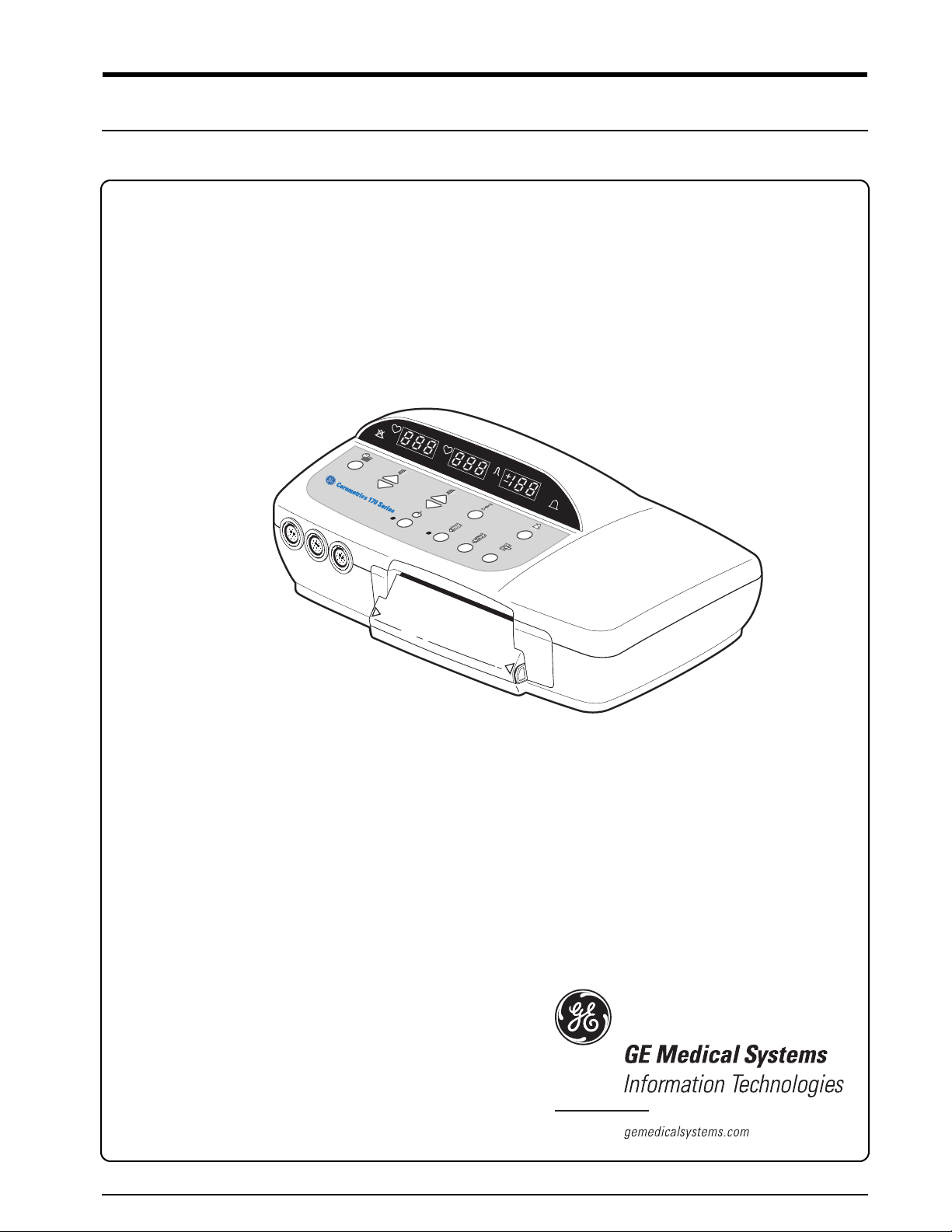
Corometrics®170 Series
SERVICE MANUAL MANUAL P/N 2000947-004 REV. C
Page 2

Page 3
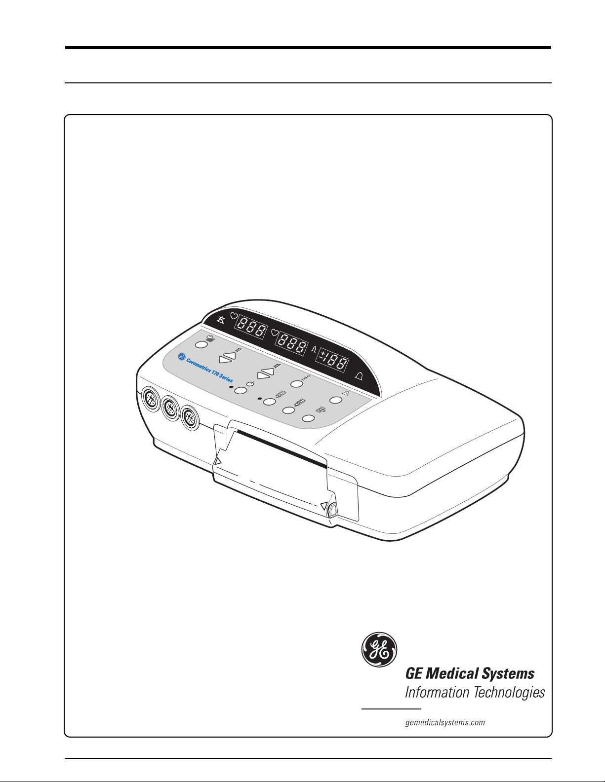
Corometrics® 170 Series
SERVICE MANUAL MANUAL P/N 2000947-004 REV. C
Page 4

GUARANTEE
All equipment sold by GE Medical Systems Information Technologies, is fully guaranteed as to
materials and workmanship for a period of 1 year. Information Technologies reserves the right to
perform guarantee service operations in its own factory, at an authorized repair station, or in the
customer’s installation.
Our obligation under this guarantee is limited to repairing, or, at our option, replacing any
defective parts of our equipment, except fuses or batteries, without charge, if such defects occur in
normal service.
Claims for damage in shipment should be filed promptly with the transportation company. All
correspondence covering the instrument should specify the model and serial numbers.
GE Medical Systems Information Technologies
A GE Medical Systems Company
GE Medical Systems Information Technologies will make available on request such circuit
diagrams, component diagrams, component parts lists, descriptions, calibration instructions, or
other information which will assist the users or appropriately qualified technical personnel to
repair those parts of the equipment which are classified by GE Medical Systems Information
Technologies as repairable. Refer to the service manual for further information.
!
CAUTION: In the United States of America, Federal Law restricts this device to sale by or
on the order of a physician.
Corometrics and Marquette are registered trademarks of GE Medical Systems Information Technologies. GE is a registered
trademark of General Electric Company. All other product and brand names are trademarks or registered trademarks of their
respective companies. ©2002-2004 GE Medical Systems Information Technologies. All rights reserved. No part of this
manual may be reproduced without the permission of GE Medical Systems Information Technologies.
Page 5

Contents
1 Safety . . . . . . . . . . . . . . . . . . . . . . . . . . . . . . . . . . . . . . . . . 1-1
General Information . . . . . . . . . . . . . . . . . . . . . . . . . . . . . . . . . . . . . . . . . . . . . . . . . . 1-2
Definitions of Terminology . . . . . . . . . . . . . . . . . . . . . . . . . . . . . . . . . . . . . . . . . . . . 1-3
Monitor Contraindications, Warnings, and Precautions . . . . . . . . . . . . . . . . . . . . 1-4
Equipment Symbols . . . . . . . . . . . . . . . . . . . . . . . . . . . . . . . . . . . . . . . . . . . . . . . . . 1-9
2 Introduction . . . . . . . . . . . . . . . . . . . . . . . . . . . . . . . . . . . . 2-1
Indications for Use . . . . . . . . . . . . . . . . . . . . . . . . . . . . . . . . . . . . . . . . . . . . . . . . . . . 2-2
Monitoring Methods . . . . . . . . . . . . . . . . . . . . . . . . . . . . . . . . . . . . . . . . . . . . . . . . . . 2-3
Features . . . . . . . . . . . . . . . . . . . . . . . . . . . . . . . . . . . . . . . . . . . . . . . . . . . . . . . . . . . 2-4
About Your Monitor . . . . . . . . . . . . . . . . . . . . . . . . . . . . . . . . . . . . . . . . . . . . . . . . . . 2-5
3 Controls, Indicators, and Connectors . . . . . . . . . . . . . . . 3-1
Front Panel Controls . . . . . . . . . . . . . . . . . . . . . . . . . . . . . . . . . . . . . . . . . . . . . . . . . 3-2
Front Panel Displays and Indicators . . . . . . . . . . . . . . . . . . . . . . . . . . . . . . . . . . . . 3-6
Front Panel Connectors . . . . . . . . . . . . . . . . . . . . . . . . . . . . . . . . . . . . . . . . . . . . . . 3-8
Strip Chart Recorder . . . . . . . . . . . . . . . . . . . . . . . . . . . . . . . . . . . . . . . . . . . . . . . . 3-12
Rear Panel Connectors . . . . . . . . . . . . . . . . . . . . . . . . . . . . . . . . . . . . . . . . . . . . . . 3-14
4 Setup Procedures . . . . . . . . . . . . . . . . . . . . . . . . . . . . . . . 4-1
Loading Strip Chart Paper . . . . . . . . . . . . . . . . . . . . . . . . . . . . . . . . . . . . . . . . . . . . 4-2
Turning the Monitor On . . . . . . . . . . . . . . . . . . . . . . . . . . . . . . . . . . . . . . . . . . . . . . . 4-7
Revision C Corometrics 170 Series 5
2000947-004
Page 6

Monitor Self-Test Routines . . . . . . . . . . . . . . . . . . . . . . . . . . . . . . . . . . . . . . . . . . . . 4-8
Customizing the Monitor . . . . . . . . . . . . . . . . . . . . . . . . . . . . . . . . . . . . . . . . . . . . . 4-10
Quick Reference Card . . . . . . . . . . . . . . . . . . . . . . . . . . . . . . . . . . . . . . . . . . . . . . . 4-18
Flasher Software Utility Upgrade . . . . . . . . . . . . . . . . . . . . . . . . . . . . . . . . . . . . . . 4-20
5 Theory of Operation . . . . . . . . . . . . . . . . . . . . . . . . . . . . . 5-1
Functional Overview . . . . . . . . . . . . . . . . . . . . . . . . . . . . . . . . . . . . . . . . . . . . . . . . . 5-2
Main Board Theory of Operation . . . . . . . . . . . . . . . . . . . . . . . . . . . . . . . . . . . . . . 5-17
FECG/IUP Board Theory of Operation . . . . . . . . . . . . . . . . . . . . . . . . . . . . . . . . . . 5-36
6 Functional Checkout Procedure . . . . . . . . . . . . . . . . . . . 6-1
Equipment Required . . . . . . . . . . . . . . . . . . . . . . . . . . . . . . . . . . . . . . . . . . . . . . . . . 6-2
General . . . . . . . . . . . . . . . . . . . . . . . . . . . . . . . . . . . . . . . . . . . . . . . . . . . . . . . . . . . . 6-3
Monitor Self-Test . . . . . . . . . . . . . . . . . . . . . . . . . . . . . . . . . . . . . . . . . . . . . . . . . . . . 6-4
Front Panel Pushbutton Test . . . . . . . . . . . . . . . . . . . . . . . . . . . . . . . . . . . . . . . . . . 6-5
Connecting the Simulator . . . . . . . . . . . . . . . . . . . . . . . . . . . . . . . . . . . . . . . . . . . . . 6-6
FECG Test . . . . . . . . . . . . . . . . . . . . . . . . . . . . . . . . . . . . . . . . . . . . . . . . . . . . . . . . . 6-7
Legplate Inspection . . . . . . . . . . . . . . . . . . . . . . . . . . . . . . . . . . . . . . . . . . . . . . . . . 6-12
Ultrasound Test . . . . . . . . . . . . . . . . . . . . . . . . . . . . . . . . . . . . . . . . . . . . . . . . . . . . 6-13
Fetal Movement Detection Test . . . . . . . . . . . . . . . . . . . . . . . . . . . . . . . . . . . . . . . 6-16
Ultrasound Transducer Test . . . . . . . . . . . . . . . . . . . . . . . . . . . . . . . . . . . . . . . . . . 6-18
Uterine Activity Test . . . . . . . . . . . . . . . . . . . . . . . . . . . . . . . . . . . . . . . . . . . . . . . . 6-19
Tocotransducer Test . . . . . . . . . . . . . . . . . . . . . . . . . . . . . . . . . . . . . . . . . . . . . . . . 6-21
Strain Gauge Transducer Test . . . . . . . . . . . . . . . . . . . . . . . . . . . . . . . . . . . . . . . . 6-22
Pattern Memory Test . . . . . . . . . . . . . . . . . . . . . . . . . . . . . . . . . . . . . . . . . . . . . . . . 6-23
Dual Heart Rate Test (Non-Pattern) . . . . . . . . . . . . . . . . . . . . . . . . . . . . . . . . . . . . 6-24
6 Corometrics 170 Series Revision C
2000947-004
Page 7

Alarm Test . . . . . . . . . . . . . . . . . . . . . . . . . . . . . . . . . . . . . . . . . . . . . . . . . . . . . . . . 6-28
7 Serviceable Assemblies . . . . . . . . . . . . . . . . . . . . . . . . . . 7-1
General Anti-Static Handling Precautions . . . . . . . . . . . . . . . . . . . . . . . . . . . . . . . . 7-2
Transducer Plug Replacement Kits . . . . . . . . . . . . . . . . . . . . . . . . . . . . . . . . . . . . . 7-3
Nautilus Transducer Cable Replacement . . . . . . . . . . . . . . . . . . . . . . . . . . . . . . . 7-15
Removing the Monitor Top Cover . . . . . . . . . . . . . . . . . . . . . . . . . . . . . . . . . . . . . 7-19
Tocotransducer Calibration . . . . . . . . . . . . . . . . . . . . . . . . . . . . . . . . . . . . . . . . . . 7-20
Nautilus Ultrasound Transducer Top Cover Replacement . . . . . . . . . . . . . . . . . 7-30
Nautilus Transducer Reassembly . . . . . . . . . . . . . . . . . . . . . . . . . . . . . . . . . . . . . 7-32
Testing a Repaired Transducer (TOCO or US) . . . . . . . . . . . . . . . . . . . . . . . . . . . 7-34
Replacing the Main Board . . . . . . . . . . . . . . . . . . . . . . . . . . . . . . . . . . . . . . . . . . . . 7-35
Replacing the FECG/IUP Board . . . . . . . . . . . . . . . . . . . . . . . . . . . . . . . . . . . . . . . 7-36
Replacing the Membrane Switch Panel . . . . . . . . . . . . . . . . . . . . . . . . . . . . . . . . . 7-37
Replacing a Front Panel Connector . . . . . . . . . . . . . . . . . . . . . . . . . . . . . . . . . . . . 7-40
Servicing the Recorder . . . . . . . . . . . . . . . . . . . . . . . . . . . . . . . . . . . . . . . . . . . . . . 7-41
Boot ROM Error Codes . . . . . . . . . . . . . . . . . . . . . . . . . . . . . . . . . . . . . . . . . . . . . . 7-49
8 Peripheral Devices . . . . . . . . . . . . . . . . . . . . . . . . . . . . . . 8-1
Remote Marks Connectors . . . . . . . . . . . . . . . . . . . . . . . . . . . . . . . . . . . . . . . . . . . . 8-2
Telemetry Connector . . . . . . . . . . . . . . . . . . . . . . . . . . . . . . . . . . . . . . . . . . . . . . . . 8-3
RS-232 Connectors . . . . . . . . . . . . . . . . . . . . . . . . . . . . . . . . . . . . . . . . . . . . . . . . . . 8-4
9 Maintenance . . . . . . . . . . . . . . . . . . . . . . . . . . . . . . . . . . . 9-1
Cleaning . . . . . . . . . . . . . . . . . . . . . . . . . . . . . . . . . . . . . . . . . . . . . . . . . . . . . . . . . . . 9-2
Preventative Maintenance Inspection . . . . . . . . . . . . . . . . . . . . . . . . . . . . . . . . . . . 9-5
Revision C Corometrics 170 Series 7
2000947-004
Page 8

10 Specifications . . . . . . . . . . . . . . . . . . . . . . . . . . . . . . . . . 10-1
General Monitor . . . . . . . . . . . . . . . . . . . . . . . . . . . . . . . . . . . . . . . . . . . . . . . . . . . . 10-2
Operating Modes . . . . . . . . . . . . . . . . . . . . . . . . . . . . . . . . . . . . . . . . . . . . . . . . . . . 10-3
Strip Chart Recorder . . . . . . . . . . . . . . . . . . . . . . . . . . . . . . . . . . . . . . . . . . . . . . . . 10-4
11 Parts Lists . . . . . . . . . . . . . . . . . . . . . . . . . . . . . . . . . . . . 11-1
2000268-188, Model 171 Final Assembly . . . . . . . . . . . . . . . . . . . . . . . . . . . . . . . . 11-2
2000268-189, Model 172 Final Assembly . . . . . . . . . . . . . . . . . . . . . . . . . . . . . . . . 11-5
2001972-037, Model 173 Final Assembly . . . . . . . . . . . . . . . . . . . . . . . . . . . . . . . . 11-8
2001972-038, Model 174 Final Assembly . . . . . . . . . . . . . . . . . . . . . . . . . . . . . . . . 11-11
2264AAX, Button-Style Nautilus Tocotranducer Assembly Parts List . . . . . . . 11-14
5700GAX, Button-Style Nautilus Ultrasound Transducer Assembly Parts List 11-15
5700KAX, Loop-Style Nautilus Ultrasound Transducer Assembly Parts List . 11-16
2264DAX, Loop-Style Nautilus Tocotransducer Assembly Parts List (5-ft cord) 11-17
1509AAO/BAO, Qwik Connect Plus Legplate Assembly Parts List . . . . . . . . . 11-18
Block Diagrams. . . . . . . . . . . . . . . . . . . . . . . . . . . . . . . . . . . . . . . . . . . . . . . . . . . . . 11-19
8 Corometrics 170 Series Revision C
2000947-004
Page 9

Chapter 1
!
Safety 1
The information presented in this section is important for the safety of both the
patient and operator and also serves to enhance equipment reliability. This chapter
describes how the terms Danger, Warning, Caution, Important, and Note are used
throughout the manual. In addition, standard equipment symbols are defined.
This section includes the following important information:
General Information . . . . . . . . . . . . . . . . . . . . . . . . . . . . . . . . . . . . . . 1-2
Definitions of Terminology . . . . . . . . . . . . . . . . . . . . . . . . . . . . . . . . 1-3
Monitor Contraindications, Warnings, and Precautions . . . . . . . . . . 1-4
Equipment Symbols . . . . . . . . . . . . . . . . . . . . . . . . . . . . . . . . . . . . . . 1-9
Revision C 170 Series Monitor 1-1
2000947-004
Page 10

Safety: General Information
General Information
General Use
If the monitor is cold to the touch or below ambient temperature, allow it to stabilize
before use.
To ensure patient safety, use only parts and accessories manufactured or
recommended by GE Medical Systems Information Technologies. Parts and
accessories used shall meet the requirements of EN60601.1.1.
Disposable devices are intended for single use only. They should not be reused.
Periodically, and whenever the integrity of the monitor is in doubt, test all functions.
Refer to the “Maternal/Fetal Monitoring Operator’s Manual” for information
concerning the limitations of internal and external fetal heart rate monitoring
techniques.
Responsibility of the Manufacturer
GE is responsible for the effects on safety, reliability, and performance if:
assembly operations, extensions, readjustments, modifications, or repairs are
carried out by persons authorized by GE;
the electrical installation of the relevant room complies with the requirements of
appropriate regulations; and
the monitor is used in accordance with the instructions of use.
Responsibility of the User
This device is intended for use by clinical professionals who are expected to know
the medical procedures, practices, and terminology required to monitor obstetrical
patients. This manual documents all possible parameters available in the 170 Series
of monitors. It is the responsibility of each hospital to ensure that the Labor and
Delivery staff is trained in all aspects of the selected model.
The 170 Series Monitor is designed to assist the perinatal staff by providing
information regarding the clinical status of the fetus during labor. The monitor does
not replace observation and evaluation of the mother and fetus at regular intervals,
by a qualified care provider, who will make diagnoses and decide on treatments or
interventions. Visual assessment of the monitor display and strip chart must be
combined with knowledge of patient history and risk factors to properly care for the
mother and fetus.
1-2 170 Series Monitor Revision C
2000947-004
Page 11

Safety: Definitions of Terminology
Definitions of Terminology
Six types of special notices are used throughout this manual. They are: Danger,
Warning, Caution, Contraindication, Important, and Note. The warnings and
cautions in this Safety section relate to the equipment in general and apply to all
aspects of the monitor. Be sure to read the other chapters because there are
additional warnings and cautions which relate to specific features of the monitor.
When grouped, warnings and cautions are listed alphabetically and do not imply any
order of importance.
Danger
Warning
Table 1-1. Definitions of Terminology
A DANGER notice indicates an imminently
hazardous situation which, if not avoided, will result
in death or serious injury.
A WARNING indicates a potentially hazardous
situation which, if not avoided, could result in death
or serious injury.
Caution
Contraindication
Important
Note
A CAUTION indicates a potentially hazardous
situation which, if not avoided, may result in minor
or moderate injury. Cautions are also used to
avoid damage to equipment.
A CONTRAINDICATION describes any special
symptom or circumstance that renders the use of a
remedy or the carrying out of a procedure
inadvisable, usually because of a risk.
An IMPORTANT notice indicates an emphasized
note. It is something you should be particularly
aware of; something not readily apparent.
A NOTE indicates a particular point of information;
something on which to focus your attention.
Revision C 170 Series Monitor 1-3
2000947-004
Page 12

Safety: Monitor Contraindications, Warnings, and Precautions
Monitor Contraindications, Warnings, and Precautions
Warnings
WARNINGS
ACCIDENTAL SPILLS—In the event that fluids are accidentally
spilled on the monitor, take the monitor out of operation and
inspect for damage.
APPLICATION—This monitor is not designed for direct cardiac
connection.
CONDUCTIVE CONNECTIONS—Avoid making any
conductive connections to applied parts (patient connection)
which are likely to degrade safety.
CONDUCTIVE PARTS—Ensure that the conductive parts of the
lead electrodes and associated connectors do not contact other
conductive parts including earth.
DEFIBRILLATION—During defibrillation, all personnel must
avoid contact with the patient and monitor to avoid a dangerous
shock hazard. In addition, proper placement of the paddles in
relation to the electrodes is required to minimize harm to the
patient.
ELECTRICAL SHOCK—To reduce the risk of electrical shock,
do not remove monitor cover. Refer servicing to qualified
personnel.
ELECTROMAGNETIC INTERFERENCE—Be aware that
strong electromagnetic fields may interfere with monitor
operation. Interference prevents the clear reception of signals by
the monitor. If the hospital is close to a strong transmitter such as
TV, AM or FM radio, police or fire stations, a HAM radio
operator, an airport, or cellular phone, their signals could be
picked up as signals by the monitor. If you feel interference is
affecting the monitor, contact your Service Representative to
check the monitor in your environment. Refer to page 1-8 for
additional information.
1-4 170 Series Monitor Revision C
2000947-004
Page 13

Safety: Monitor Contraindications, Warnings, and Precautions
WARNINGS
ELECTROSURGERY—The monitor is not designed for use with
high-frequency surgical devices. In addition, measurements may
be affected in the presence of strong electromagnetic sources such
as electrosurgery equipment.
EXPLOSION HAZARD—Do not use this equipment in the
presence of flammable anesthetics or inside an oxygen tent.
GROUNDING—Do not defeat the three-wire grounding feature
of the power cord by means of adaptors, plug modifications, or
other methods. A dangerous shock hazard to both patient and
operator may result.
INSTRUCTIONS—For continued and safe use of this equipment,
it is necessary to follow all listed instructions. However, the
instructions provided in this manual in no way supersede
established medical procedures concerning patient care. The
monitor does not replace observation and evaluation of the
patient, at regular intervals, by a qualified care provider who will
make diagnoses and decide on treatments and interventions.
INTERFACING OTHER EQUIPMENT—Monitoring equipment
must be interfaced with other types of medical equipment by
qualified biomedical engineering personnel. Be certain to consult
manufacturers’ specifications to maintain safe operation.
LEAKAGE CURRENT TEST—The interconnection of auxiliary
equipment with this device may increase the total leakage current.
When interfacing with other equipment, a test for leakage current
must be performed by qualified biomedical engineering personnel
before using with patients. Serious injury or death could result if
the leakage current exceeds applicable standards. The use of
accessory equipment not complying with the equivalent safety
requirements of this equipment may lead to a reduced level of
safety of the resulting system. Consideration relating to the
choice shall include: use of the accessory in the patient vicinity;
and evidence that the safety certification of the accessory has been
performed in accordance with the appropriate EN60601.1 and/or
EN60601.1.1 harmonized national standard.
Revision C 170 Series Monitor 1-5
2000947-004
Page 14

Safety: Monitor Contraindications, Warnings, and Precautions
WARNINGS
LINE ISOLATION MONITOR TRANSIENTS—Line isolation
monitor transients may resemble actual cardiac waveforms, and
thus cause incorrect heart rate determinations and alarm activation
(or inhibition).
STRANGULATION—Make sure all patient cables, leadwires,
and tubing are positioned away from the patient’s head to
minimize the risk of accidental strangulation.
WATER BIRTHS—Do not use the monitor to directly monitor
patients during water births, in whirlpool or submersion water
baths, during showers, or in any other situation where the mother
is immersed in water. Doing so may result in electrical shock
hazard.
1-6 170 Series Monitor Revision C
2000947-004
Page 15

Cautions
Safety: Monitor Contraindications, Warnings, and Precautions
CAUTIONS
ANNUAL SERVICING—For continued safety and performance
of the monitor, it is recommended that the calibration, accuracy,
and electrical safety of the monitor be verified on an annual basis
by an GE Service Representative.
DAILY TESTING—It is essential that the monitor and
accessories be inspected every day. It is recommended practice to
initiate the monitor’s self-test feature at the beginning of each
monitoring session; follow the instructions in “Chapter 4, Setup
Procedures”.
ENVIRONMENT—The performance of the monitor has not been
tested in certain areas, such as x-ray and imaging suites. The
monitor is not recommended for use in these environments.
PERFORMANCE—Report all problems experienced with the
monitor. If the monitor is not working properly, contact your
Service Representative for service. The monitor should not be
used if it is not working properly.
PINCHING—Keep fingers clear of the paper roller because the
roller could pinch your fingers.
TRAPPING—Keep hands, hair, jewelry, and loose clothing away
from the paper roller because the roller could trap these items.
TRIPPING—Arrange monitoring equipment so that cords and
cables do not present a tripping hazard.
Revision C 170 Series Monitor 1-7
2000947-004
Page 16

Safety: Monitor Contraindications, Warnings, and Precautions
Electromagnetic Interference
This device has been tested and found to comply with the limits for medical devices
to the IEC 601-1-2:1993, EN60601-1-2:1994, Medical Device Directive 93/42/EEC.
These limits are designed to provide reasonable protection against harmful
interference in a typical medical installation.
However, because of the proliferation of radio-frequency transmitting equipment
and other sources of electrical noise in the health-care and home environments (for
example, cellular phones, mobile two-way radios, electrical appliances), it is
possible that high levels of such interference due to close proximity or strength of a
source, may result in disruption of performance of this device.
This equipment generates, uses, and can radiate radio frequency energy and, if not
installed and used in accordance with these instructions, may cause harmful
interference with other devices in the vicinity. Disruption or interference may be
evidenced by erratic readings, cessation of operation, or incorrect functioning. If this
occurs, the site of use should be surveyed to determine the source of this disruption,
and actions taken to eliminate the source.
The user is encouraged to try to correct the interference by one or more of the
following measures:
Turn equipment in the vicinity off and on to isolate the offending equipment.
Reorient or relocate the other receiving device.
Increase the separation between the interfering equipment and this equipment.
If assistance is required, contact your GE Service Representative.
1-8 170 Series Monitor Revision C
2000947-004
Page 17
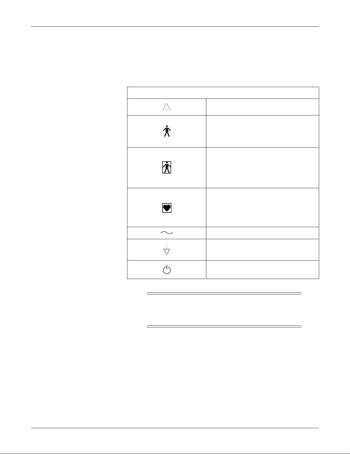
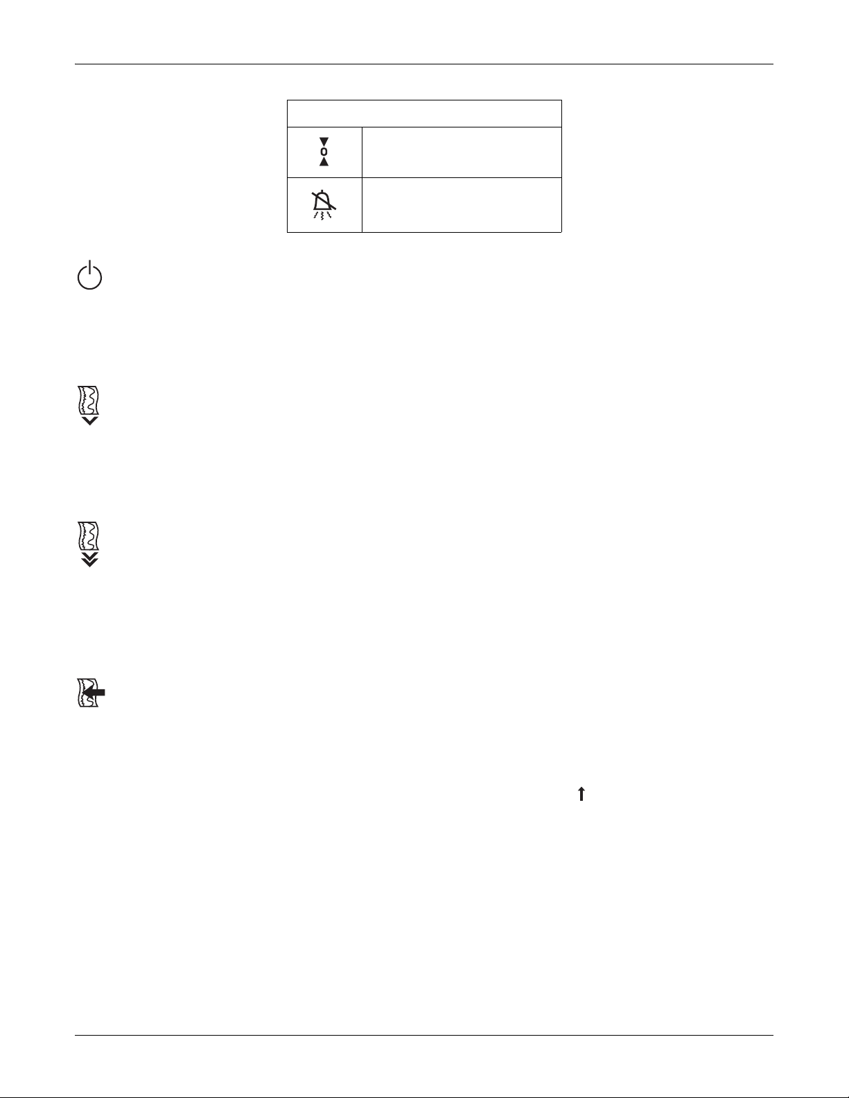
Equipment Symbols
The following is a list of symbols used on products manufactured by GE. Some
symbols may not appear on your unit.
Safety: Equipment Symbols
Table 1-2. Equipment Symbols
!
ATTENTION: Consult accompanying documents.
TYPE B EQUIPMENT. Type B equipment is
suitable for intentional external and internal
application to the patient, excluding direct cardiac
application.
TYPE BF EQUIPMENT.
suitable for intentional external and internal
application to the patient, excluding direct cardiac
application. Type BF equipment has an F-type
applied part.
TYPE CF EQUIPMENT. Type CF equipment is
suitable for intentional external and internal
application to the patient, including direct cardiac
application. Type CF equipment has an F-type
applied part.
ALTERNATING CURRENT (AC).
EQUIPOTENTIALITY.
ON/STANDBY: button toggles between full power
and standby.
Type BF equipment is
CAUTION
AC MAINS—The On/Standby switch does not disconnect the
monitor from AC mains power. To completely remove power, you
must disconnect the power cord from the AC wall outlet.
Revision C 170 Series Monitor 1-9
2000947-004
Page 18

For your notes
Safety: Equipment Symbols
1-10 170 Series Monitor Revision C
2000947-004
Page 19

Chapter 2
Introduction 2
This section lists the indications for use for monitors in the 170 Series as well as
provides an explanation of the different patient monitoring modalities.
This section summarizes the clinical applications of monitors in the 170 Series:
Indications for Use . . . . . . . . . . . . . . . . . . . . . . . . . . . . . . . . . . . . . . . 2-2
Monitoring Methods. . . . . . . . . . . . . . . . . . . . . . . . . . . . . . . . . . . . . . 2-3
Features . . . . . . . . . . . . . . . . . . . . . . . . . . . . . . . . . . . . . . . . . . . . . . . 2-4
About Your Monitor. . . . . . . . . . . . . . . . . . . . . . . . . . . . . . . . . . . . . . 2-5
Revision C 170 Series Monitor 2-1
2000947-004
Page 20

Indications for Use
Models 171 and 172
Models 171 and 172 Fetal Monitors are indicated for use in the monitoring of the
fetus during the antepartum period as well as throughout labor and delivery. Each
monitor also has an optional monitoring mode to detect fetal body movements.
Models 173 and 174
Models 173 and 174 Fetal Monitors are indicated for use in the monitoring of the
fetus throughout labor and delivery. Each monitor also has an optional monitoring
mode to detect fetal body movements.
Introduction: Indications for Use
2-2 170 Series Monitor Revision C
2000947-004
Page 21

Introduction: Monitoring Methods
Monitoring Methods
The following is a summary of all the clinical monitoring methods found in the 170
Series.
Fetal Heart Rate
External Method, Pulsed Doppler Ultrasound
Ultrasound monitoring is available on all 170 Series Monitors. Models 171 and 173
provide a single ultrasound channel, while Models 172 and 174 provide two
ultrasound channels.
Fetal heart rate can be measured externally using pulsed Doppler Ultrasound. A
transducer placed on the mother’s abdomen is used to direct an ultrasonic beam
toward the fetal heart and to sense Doppler shifted echoes created by moving cardiac
structures. A patented autocorrelation process is used to determine the timing of
successive cardiac cycles. The resulting fetal heart rate (FHR) pattern is recorded on
the strip chart paper and the FHR appears on the digital display.
Internal Method, Direct Fetal Electrocardiogram (FECG)
FECG is available on Models 173 and 174 only. The Model 173 provides a
dedicated FECG connector. The Model 174 provides a combi-connector which can
be used for either FECG or US.
FECG signals are obtained via a spiral electrode attached to the fetal presenting part.
FHR is computed on a beat-to-beat basis using the R-to-R time interval of the QRS
complexes. The instantaneous FHR pattern is printed on the strip chart paper and
the FHR appears on the digital display.
Maternal Uterine Activity
External Method, Tocotransducer (TOCO)
Maternal uterine activity is measured externally using a tocotransducer (toco).
Relative pressure within the uterus is measured using a tocotransducer attached to
the mother’s abdomen in the area of the uterine fundus. The readings are plotted on
the strip chart paper in a relative scale from 0 to 100 as well as shown on the digital
display. All 170 Series Monitors provide external uterine activity monitoring.
Internal Method, Intrauterine Pressure Catheter and Strain Gauge (IUP)
IUP is available on Models 173 and 174 only.
Intrauterine pressure is measured using a transcervical catheter. The pressure trend
is plotted over the range of 0 to 100 mmHg and the readings appear on the digital
display.
Revision C 170 Series Monitor 2-3
2000947-004
Page 22

Features
Introduction: Features
The 170 Series is a family of fetal monitors offering various combinations of
modalities to suit your institution’s needs. Each monitor boasts the following
qualities:
The strip chart recorder is a quiet, easy-to-load, high resolution thermal array
printer. The recorder prints continuous trends and alphanumeric data on one
strip chart.
Automatic mode selection is provided simply by inserting the appropriate
transducer plug into the front panel receptacle.
Wide beam ultrasound transducer provides an advanced level of system
performance.
Transducer connectors are easy-to-use, color-coded, and durable.
Frequently-used functions are controlled by front panel buttons—including
audio volume, uterine activity reference, alarm silence, event mark, paper
advance, and user setup controls.
The ultrasound mode provides clean accurate traces with few “dropouts”
because of a patented autocorrelation processing.
Fetal heart rate alarm limits are user-defined, with pre-set defaults.
Alarm silencing is controlled by a front panel pushbutton—colored for easy
recognition.
Fetal heart rate alarm conditions have both audible and visual indications. The
audible indicator can be silenced on an alarm-by-alarm basis.
Two RS-232C ports provide interfacing to external devices.
2-4 170 Series Monitor Revision C
2000947-004
Page 23

About Your Monitor
This manual describes all monitors in the 170 Series; therefore some sections may
not apply to your model monitor. Refer to Table 2-1.
Model 171
The Model 171 Antepartum Fetal Monitor provides singleton ultrasound and
external uterine activity monitoring.
Model 172
The Model 172 Antepartum Fetal Monitor provides dual ultrasound and external
uterine activity monitoring.
Model 173
The Model 173 Intrapartum Monitor provides dual heart rate monitoring using
FECG and ultrasound. The monitor also provides external uterine activity
monitoring using a tocotransducer or internal monitoring using an intrauterine
pressure catheter (IUPC).
Introduction: About Your Monitor
Model 174
The Model 174 Intrapartum Monitor provides dual heart rate monitoring using
FECG/ultrasound or dual ultrasound. The monitor also provides external uterine
activity monitoring using a tocotransducer or internal monitoring using an IUPC.
Table 2-1. Summary of Features
Feature 171 172 173 174
External uterine activity (TOCO) 9999
Internal uterine activity (IUPC) 99
Ultrasound
Dual ultrasound 99
FECG
Fetal heart rate alarms 9999
Fetal movement detection (optional) 9999
Heartbeat coincidence 999
Fetal heart rate offset 999
a
a
a
The Model 174 has a combi-connector for the primary FHR that can be used for either US or FECG.
9999
99
Revision C 170 Series Monitor 2-5
2000947-004
Page 24

For your notes
2-6 170 Series Monitor Revision C
2000947-004
Page 25

Chapter 3
Controls, Indicators, and Connectors
This section describes all possible controls, indicators, and connectors in the 170
Series.
This section contains the following information:
Front Panel Controls. . . . . . . . . . . . . . . . . . . . . . . . . . . . . . . . . . . . . . 3-2
Front Panel Displays and Indicators. . . . . . . . . . . . . . . . . . . . . . . . . . 3-6
Front Panel Connectors . . . . . . . . . . . . . . . . . . . . . . . . . . . . . . . . . . . 3-8
Strip Chart Recorder. . . . . . . . . . . . . . . . . . . . . . . . . . . . . . . . . . . . . 3-12
Rear Panel Connectors . . . . . . . . . . . . . . . . . . . . . . . . . . . . . . . . . . . 3-14
3
Revision C 170 Series Monitor 3-1
2000947-004
Page 26
Controls, Indicators, and Connectors: Front Panel Controls
Front Panel Controls
Figure 3-1. Front Panel Controls (Model 172 shown)
Table 3-1. Front Panel Controls
Symbol Name
Power
Record
Paper Advance
Mark/Offset
Setup
Volume
3-2 170 Series Monitor Revision C
2000947-004
Page 27
Controls, Indicators, and Connectors: Front Panel Controls
Table 3-1. Front Panel Controls
Power Button and Indicator
Pressing the blue Power button turns the monitor on and illuminates the green
indicator to the left of the button. Pressing the button again puts the monitor in
standby and extinguishes the indicator.
Record Button and Indicator
Pressing the Record pushbutton activates the recorder, provided paper is installed;
the amber indicator illuminates to the left of the button. Pressing the button again
turns the recorder off and extinguishes the indicator.
UA Reference
Alarm Silence
Paper Advance Button
Pressing the Paper Advance button causes the recorder to advance chart paper at a
rate of 40 cm/min for as long as the button is pressed. If the recorder is on, twenty
seconds after the button is released, the recorder prints the time, date, active trends
legends, and chart speed.
Mark/Offset Button
The Mark/Offset button is a multifunction button:
Mark
Briefly pressing the button prints an event mark on the bottom two lines of the
heart rate grid.
Offset (Models 172, 173, and 174 Only)
When the heart rate offset mode is enabled, pressing and holding the Mark/Offset
button for at least two seconds shifts the secondary FHR trend +20 BPM for
visibility purposes. You will hear a “beep” for confirmation. Refer to the “170
Series Operator’s Manual” for more information.
Revision C 170 Series Monitor 3-3
2000947-004
Page 28

Controls, Indicators, and Connectors: Front Panel Controls
Setup Button
Volume Buttons
Model 171
Models 172, 173, and 174
Pressing and holding this button while the monitor is on enters a user setup mode for
configuring the monitor.
Pressing and holding this button during power up enters a service setup mode.
Refer to “Chapter 4, Setup Procedures” for instructions.
The Volume buttons are used to raise ( ) and lower ( ) the volume of the audio
signals emitted by the speaker. The volume buttons are also used during setup.
This monitor has two volume buttons used to control the ultrasound audio.
These monitors have four volume buttons. The left pair controls the audio signals
for the mode shown in the primary FHR display; likewise, the right pair of buttons
controls the audio for the mode shown in the secondary FHR display.
Setup Mode
When the monitor is in setup mode (user or service), the volume buttons change: the
setting or value shown in the FHR display; or the monitor feature code shown in the
UA display. (For Models 172, 173, and 174, only the leftmost volume controls are
active during setup mode.)
3-4 170 Series Monitor Revision C
2000947-004
Page 29

Controls, Indicators, and Connectors: Front Panel Controls
UA Reference Button
The UA Reference button is used to set the uterine activity pressure reference. This
button is also used during setup.
Setting a Baseline for External Monitoring (Tocotransducer)
Briefly pressing the UA Reference button sets the pressure baseline at a preset
default. The monitor is shipped from the factory with a default setting of 10 relative
units. Qualified service personnel can access a service screen to set the default to 5,
10, 15, 20, or 25 relative units.
Pressing this button for more than two seconds causes the uterine activity reference
value to override the default setting and cycle through all available selections: 5, 10,
15, 20, or 25 relative units, starting at the default setting—until the button is
released. While the button is held down, the strip chart tracing remains unchanged.
Once the button is released, the recorder trace takes on this new value. This value is
stored as the new baseline for the currently measured uterine activity signal.
Setting a Baseline for Internal Monitoring (IUPC)
Pressing the UA Reference button sets the pressure baseline at 0 mmHg.
Setup Mode
Alarm Silence Button
NOTE: IUPC monitoring is only available on Models 173 and 174.
When the monitor is in setup mode, the UA Reference button selects the active
display. Pressing the button alternates between the UA display (which shows a
monitor feature code) and the FHR display (which shows the setting or value for the
selected feature code). When the UA display is active, the ± sign lights. When the
FHR display is active, the heartbeat indicator lights.
This button is yellow for easy recognition. Pressing the Alarm Silence button
removes the audible indication of an individual fetal heart rate alarm.
NOTE: Silencing an alarm does not affect the visual indications.
Revision C 170 Series Monitor 3-5
2000947-004
Page 30
Controls, Indicators, and Connectors: Front Panel Displays and Indicators
Front Panel Displays and Indicators
Fetal Heart Rate Display(s) and Indicator(s)
FHR Display
A three-digit yellow numeric display indicates the fetal heart rate in beats per
minute. The value flashes during an alarm condition.
Heartbeat Indicator
A yellow heart shaped indicator flashes with each detected valid heartbeat for the
fetal heart.
Primary Versus Secondary (Models 172, 173, and 174 only)
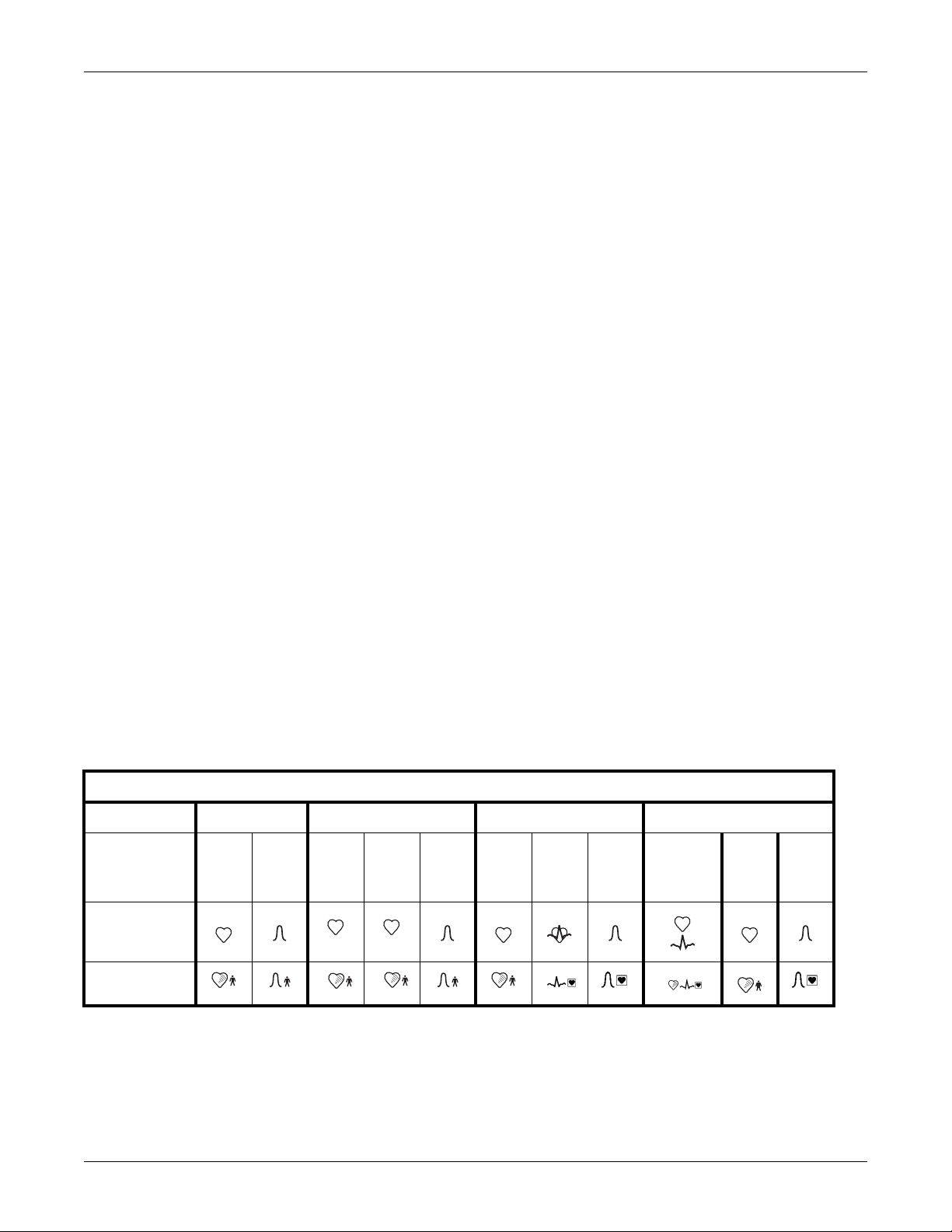
Refer to Table 3-2 for a summary of display positions relative to connectors.
Uterine Activity Display
This green three-digit display indicates the uterine activity values.
Tocotransducer
If uterine activity is measured using a tocotransducer, the uterine activity value
displays in relative units. A plus sign flashes when the uterine activity value
exceeds the strip chart range of 100 relative units.
IUP (Models 173 and 174 Only)
If uterine activity is measured using an intrauterine pressure catheter or a strain
gauge pressure transducer, the uterine activity value displays in mmHg.
.
Table 3-2. Display/Connector Summary
Monitor Model 171 Model 172 Model 173 Model 174
Mode US TOCO US1 US2 TOCO US FECG
Display
1 2
TOCO
or
IUP
US1
or
FECG
US2
TOCO
or
IUP
Connector
3-6 170 Series Monitor Revision C
1
2
2000947-004
Page 31

Controls, Indicators, and Connectors: Front Panel Displays and Indicators
Alarms Disabled Indicator
Audio Alarm Indicator
Active Patient Alarms
Resolved Patient Alarms
Signal Quality Alarms
This yellow indicator illuminates when all alarms have been disabled. The indicator
is unlit when alarms are enabled. Refer to “Chapter 4, Setup Procedures” for
information on enabling/disabling alarms.
For active patient alarms, this yellow indicator flashes; it continues to flash even if
the alarm is silenced.
For resolved patient alarms, the indicator continues to flash until you silence the
alarm. This ensures that the alarm is acknowledged by a clinician.
For signal quality alarms, the indicator flashes during an active alarm and turns off
as soon as the condition is resolved. The indicator is unaffected by silencing the
audio alarm.
Revision C 170 Series Monitor 3-7
2000947-004
Page 32

Controls, Indicators, and Connectors: Front Panel Connectors
Front Panel Connectors
Model 171 Connectors
Ultrasound Connector
The ultrasound connector1 is a blue, round receptacle mechanically keyed to accept
only a Corometrics ultrasound transducer plug. The fetal heart rate derived from
this transducer shows in the fetal heart rate display.
Figure 3-2. Model 171 Connectors
Uterine Activity Connector
The uterine activity connector is a white, round receptacle mechanically keyed to
accept a Corometrics tocotransducer. The uterine activity value obtained from this
transducer shows in the uterine activity display.
1
If the Model 171 is interfaced to a clinical information system (CIS), be aware that the CIS may be
designed to alarm when there is no fetal heart rate signal. Therefore it is recommended that you
unplug the ultrasound transducer from the monitor, when not in use, to eliminate false alarms.
3-8 170 Series Monitor Revision C
2000947-004
Page 33

Controls, Indicators, and Connectors: Front Panel Connectors
Model 172 Connectors
1
2
Primary Ultrasound Connector
Secondary Ultrasound Connector
Uterine Activity Connector
1
Figure 3-3. Model 172 Connectors
The primary ultrasound connector1 is a blue, round receptacle mechanically keyed
to accept only a Corometrics ultrasound transducer plug. The fetal heart rate derived
from this transducer shows in the primary fetal heart rate display.
The secondary ultrasound connector1 is a blue, round receptacle identical to the
primary ultrasound connector described above. The fetal heart rate derived from
this connector displays in the secondary fetal heart rate display.
The uterine activity connector is a white, round receptacle mechanically keyed to
accept a Corometrics tocotransducer. The uterine activity value obtained from this
transducer shows in the uterine activity display.
2
1
If the Model 172 is interfaced to a clinical information system (CIS), be aware that the CIS may be
designed to alarm when there is no fetal heart rate signal. Therefore it is recommended that you
unplug the ultrasound transducer(s) from the monitor, when not in use, to eliminate false alarms.
Revision C 170 Series Monitor 3-9
2000947-004
Page 34

Controls, Indicators, and Connectors: Front Panel Connectors
Model 173 Connectors
Ultrasound Connector
Figure 3-4. Model 173 Connectors
The ultrasound connector1 is a blue, round receptacle mechanically keyed to accept
only a Corometrics ultrasound transducer plug. The fetal heart rate derived from
this transducer shows in the primary fetal heart display.
FECG Connector
The FECG connector1 is a dark grey, round receptacle mechanically keyed to
accept a Corometrics FECG cable/legplate plug. The fetal heart rate derived from
the spiral electrode displays in the secondary fetal heart rate display.
Uterine Activity Connector
The uterine activity connector is a white, round receptacle mechanically keyed to
accept a Corometrics tocotransducer, a Corometrics strain gauge transducer plug, or
any intrauterine pressure catheter with compatible cable plug. The uterine activity
value obtained from this transducer shows in the uterine activity display.
1
If the Model 173 is interfaced to a clinical information system (CIS), be aware that the CIS may be
designed to alarm when there is no fetal heart rate signal. Therefore it is recommended that you
unplug the ultrasound and/or FECG transducers from the monitor, when not in use, to eliminate false
alarms.
3-10 170 Series Monitor Revision C
2000947-004
Page 35

Controls, Indicators, and Connectors: Front Panel Connectors
Model 174 Connectors
Combi-Connector (Primary Ultrasound or FECG)
Figure 3-5. Model 174 Connectors
The combi-connector is a blue connector1 with a dark grey inner center. This round
receptacle is mechanically keyed to accept only a Corometrics ultrasound transducer
plug or a Corometrics FECG cable/legplate plug. The fetal heart rate derived from
this transducer or cable/legplate shows in the primary fetal heart display.
IMPORTANT
COMBI-CONNECTOR—The combi-connector can be used for
monitoring ultrasound or FECG depending on what you plug in
(US transducer or FECG cable/legplate). When used in
conjunction with the secondary ultrasound connector, you have
the option of monitoring twins using dual US or FECG/US.
Secondary Ultrasound Connector
The secondary ultrasound connector1 is a blue, round receptacle mechanically
keyed to accept only a Corometrics ultrasound transducer plug. The fetal heart rate
derived from this connector shows in the secondary fetal heart rate display.
Uterine Activity Connector
The uterine activity connector is a white, round receptacle mechanically keyed to
accept a Corometrics tocotransducer, a Corometrics strain gauge transducer plug, or
any intrauterine pressure catheter with compatible cable plug. The uterine activity
value obtained from this transducer shows in the uterine activity display.
1
If the Model 174 is interfaced to a clinical information system (CIS), be aware that the CIS may be
designed to alarm when there is no fetal heart rate signal. Therefore it is recommended that you
unplug the ultrasound and/or FECG transducers from the monitor, when not in use, to eliminate false
alarms.
Revision C 170 Series Monitor 3-11
2000947-004
Page 36

Controls, Indicators, and Connectors: Strip Chart Recorder
Strip Chart Recorder
4305AAO
bpm
150
180
210
240
FHR
30
60
90
120
8
12
10
Figure 3-6. Strip Chart Recorder
UA
kPa
0
426
Heart Rate Grid
The strip chart recorder is located on the right side of the front panel. Latches on
each side of the recorder open the paper drawer.
Two styles of paper are available: 30-240 BPM scale and 50-210 BPM scale.
Refer to “Chapter 4, Setup Procedures” for instructions on loading strip chart paper
into the recorder.
One or two fetal heart rate trends print in the top (or left) grid of the strip chart
paper—depending on your model monitor and the active modalities.
If only one fetal heart rate is being monitored, the FHR trend is printed in black. If
twins are being monitored, the primary trend is printed in plain black while the
secondary trend is bolded.
Refer to the “170 Series Operator’s Manual” for additional information about fetal
heart rate trends and annotations.
3-12 170 Series Monitor Revision C
2000947-004
Page 37

Controls, Indicators, and Connectors: Strip Chart Recorder
Uterine Activity Grid
Annotation Area
The uterine activity trend prints in black on the bottom (or right) grid of the strip
chart paper.
Refer to the “170 Series Operator’s Manual” for more information about uterine
activity trends and annotations.
An annotation area is provided between the fetal heart rate and uterine activity grids.
Revision C 170 Series Monitor 3-13
2000947-004
Page 38

Controls, Indicators, and Connectors: Rear Panel Connectors
Rear Panel Connectors
CONNECT TO:
GE MEDICAL SYSTEMS
REF 7714AAT ONLY
Figure 3-7. Rear Panel Connectors
RS232 RS232
12
Power Supply Connector
This is the receptacle for the AC adapter, P/N 7714AAT only. A line cord connects
from the other end of the adapter to an AC wall outlet. The connector is labeled
CONNECT TO GE MEDICAL SYSTEMS REF 7714AAT ONLY. The power supply is a
universal AC-to-DC converter which can accept an AC input in the range 100–230
VAC. The converter supplies a regulated 12 Vdc to the monitor.
Remote Mark Connector
This connector is provided for attaching an optional Corometrics Model 146 Fetal
Acoustic Stimulator (FAST). The annotation
the Model 146 is used.
Remote Mark Connector
This connector is provided for attaching an optional Corometrics Remote Event
Marker. This accessory annotates the strip chart recorder paper with a marker which
can be configured as one of the following:
The monitor is factory set to use the annotation. Refer to the “Chapter 4, Setup
Procedures” for information about selecting the annotation.
prints on the strip chart each time
: This annotation is commonly used to record an “event.”
FM
: This annotation is commonly used as an indication that the mother has
perceived fetal movement.
FM
3-14 170 Series Monitor Revision C
2000947-004
Page 39

Controls, Indicators, and Connectors: Rear Panel Connectors
Nurse Call Interface
RS-232C Connectors
This connector is intended for future interfacing to a standard Nurse Call System.
Two RS-232C connectors are provided for interfacing to peripheral equipment such
as:
a maternal non-invasive blood pressure monitor
a central information system that uses Hewlett-Packard’s Digital Series
Interface Protocol
Contact your Service Representative for more information.
CAUTION
NON-DESTRUCTIVE VOLTAGE—The maximum nondestructive voltage that may be applied to the rear panel
connectors is 0 V. Do not attempt to connect cables to these
connectors without contacting your Biomedical Engineering
Department or Service Representative. This is to ensure the
connectors comply with leakage-current requirements of one of
the following applicable standards: Underwriters Laboratories
UL-2601.1, Canadian Standards Associations CSA 22.2 No. 125,
or International Electrotechnical Commission EN60601.1.
Telemetry Connector
This high-density 15-pin connector is intended for future interfacing to the receiver
of a Corometrics telemetry system. Contact your Service Representative for more
information.
IMPORTANT
TELEMETRY—For proper operation when using a telemetry
system, disconnect all transducers from the front panel of the 170
Series Monitor. Refer to the operator’s manual for your telemetry
system for more information.
Revision C 170 Series Monitor 3-15
2000947-004
Page 40

For your notes
3-16 170 Series Monitor Revision C
2000947-004
Page 41

Chapter 4
Setup Procedures 4
This section contains information about configuring a 170 Series Monitor to meet
the individual needs of your clinic or hospital. Use of the monitor will vary
according to the accessories attached to it, the clinical applications in which it is
used, and the personal preferences of the users.
This chapter lists all available user setup options in the monitor and provides stepby-step instructions for making selections:
Loading Strip Chart Paper . . . . . . . . . . . . . . . . . . . . . . . . . . . . . . . . . 4-2
Turning the Monitor On . . . . . . . . . . . . . . . . . . . . . . . . . . . . . . . . . . . 4-7
Recorder Test . . . . . . . . . . . . . . . . . . . . . . . . . . . . . . . . . . . . . . . . . . . 4-9
Customizing the Monitor . . . . . . . . . . . . . . . . . . . . . . . . . . . . . . . . . 4-10
Printing a Summary of Configuration Settings . . . . . . . . . . . . . . . . 4-17
Quick Reference Card . . . . . . . . . . . . . . . . . . . . . . . . . . . . . . . . . . . 4-18
Flasher Software Utility Upgrade . . . . . . . . . . . . . . . . . . . . . . . . . . 4-20
Revision C 170 Series Monitor 4-1
2000947-004
Page 42

Setup Procedures: Loading Strip Chart Paper
Loading Strip Chart Paper
The required paper for use with the 170 Series Monitor is:
catalog number (REF) 4305AAO/CAO
(HR scale of 30–240 BPM); or
catalog number (REF) 4305BAO/DAO
(HR scale of 50–210 BPM).
CAUTIONS
LOADING PAPER—The instructions for loading paper into a
120 or 170 Series Monitor are different than the instructions for
loading paper into other Corometrics monitors with which you
may be familiar. Improper loading can cause paper jams. Follow
the instructions carefully.
PAPER TYPE—Do not use non-Corometrics paper or paper
designed for use with other Corometrics monitors. Using paper
other than catalog number (REF) 4305AAO/BAO/CAO/DAO:
may produce inferior print quality; could result in permanent
damage to the recorder’s print head; and may void your warranty.
STORAGE/TRANSPORT—Paper should be installed in the
monitor’s strip chart recorder at all times. This reduces particle
build up on the printhead and facilitates opening the recorder door.
To protect against paper jams, the 170 Series recorder contains a paper-loading
sensor which detects if the paper has been incorrectly loaded. When the recorder
detects a paper-load–error condition:
the recorder will not print;
the Record indicator flashes on and off every second; and
three short beeps (low tones) sound every three seconds at a fixed volume.
The most likely cause of a paper-load–error condition is that you loaded the paper
with the black squares facing up. The correct method is to load the paper with the
black squares down, as explained later in this section.
4-2 170 Series Monitor Revision C
2000947-004
Page 43

Setup Procedures: Loading Strip Chart Paper
To install Corometrics catalog number (REF) 4305AAO/BAO/CAO/DAO chart
paper in the 170 Series Monitor, follow these steps:
CAUTION
LOADING PAPER—Paper loading instructions for a 170 or 120
Series Monitor are different than other Corometrics monitors with
which you may be familiar.
1. Press on each side of the paper drawer to release the drawer latches.
Figure 4-1. Releasing the Drawer Latches
2. Slide the paper drawer out toward you.
Figure 4-2. Opening the Paper Drawer
3. Remove the plastic wrapper from the paper and discard.
Revision C 170 Series Monitor 4-3
2000947-004
Page 44

Setup Procedures: Loading Strip Chart Paper
4. Fan the pack of Z-fold paper on all sides to loosen any folds and to ensure
proper feed of the paper throughout the recorder.
Figure 4-3. Fanning the Paper
5. Hold the package of paper so that:
the black squares are on the bottom of the pack; and
the Information Technologies name and page numbers are on the left side
of the pack.
NOTE: The black squares indicate the end of the recorder paper. When the black
squares appear, the strip chart recorder has approximately 20 minutes of
paper remaining, when running at a speed of 3 cm/min.
Figure 4-4. Orienting the Paper
4-4 170 Series Monitor Revision C
2000947-004
Page 45

Setup Procedures: Loading Strip Chart Paper
6. Unfold two sheets from the top of the pack so that they extend toward you.
Figure 4-5. Creating a Paper Leader
7. Place the pack in the drawer so that the pack is laying flat in the bottom of the
paper tray.
Figure 4-6. Inserting the Paper
Revision C 170 Series Monitor 4-5
2000947-004
Page 46

Pull paper
leader taut
Remaining paper
lays flat in drawer
Setup Procedures: Loading Strip Chart Paper
8. Pull the paper leader taut at an angle between remaining pack and the paper
guides. The balance of the paper pack should stay flat in the drawer as shown in
Figure 4-7. (The paper guides are shown in Figure 4-8.)
Figure 4-7. Paper Drawer Side Cutaway View
9. Slide the drawer closed by exerting even pressure on both sides of the drawer.
Avoid skewing the drawer in its tracks. (The pre-printed vertical lines on the
paper should be parallel to the printhead.) You will hear a click when the
drawer is locked in place.
Paper Guide
90
60
30
Printhead
12
10
8
6
4
2
A
U
a
kP
0
Paper Guide
bpm
240
210
180
R
H
F
150
O
A
5A
430
120
Figure 4-8. Closing the Paper Drawer
IMPORTANT
PAPER—Paper should always be installed in the monitor. The
monitor runs a self-test routine each time it is powered on; part of
this routine includes a recorder test.
4-6 170 Series Monitor Revision C
2000947-004
Page 47

Setup Procedures: Turning the Monitor On
Turning the Monitor On
The 170 Series uses a universal AC-to-DC converter which accepts an AC input in
the range 100–230 VAC. The converter supplies a regulated 12 Vdc to the 170
Series Monitor.
1. Connect the AC adapter into the power supply connector labeled:
GE MEDICAL SYSTEMS REF 7714AAT ONLY
Figure 4-9. Connecting the AC Adapter
2. Connect one end of the detachable line cord to the AC adapter; connect the
other end into a hospital grade grounded wall outlet.
.
CONNECT TO
3. Press the monitor’s
illuminates. A self-test routine automatically runs. Read "Monitor Self-Test
Routines" on the next page.
Power button . The green indicator next to the button
Figure 4-10. Turning the Monitor On
Revision C 170 Series Monitor 4-7
2000947-004
Page 48

Setup Procedures: Monitor Self-Test Routines
Monitor Self-Test Routines
NOTE: Ensure paper is installed in the recorder in order to verify a successful
recorder test.
Each 170 Series Monitor contains a self-test routine which checks the internal
circuitry of the monitor, the displays and indicators, and the strip chart recorder.
The self-test routine is automatically initiated each time you turn on the monitor.
CAUTION
SELF-TEST FAILURE—If there is any problem with the self-test
routine, turn off the monitor and remove it from operation. Notify
your Biomedical Engineering Department or Service
Representative.
After completion of a successful self-test routine, the monitor is ready for use.
NOTE: If the recorder was off at the time the monitor was turned off, the test
routine will turn the recorder on, then turn it off after the tests are complete.
If the recorder was on at the time the monitor was turned off, the tests will
be performed and the recorder will remain on.
Table 4-1. Summary of Self-Test Routines
Test Description What to Verify
Display/Indicator Test: All displays and indicators
illuminate.
Internal Test: The internal circuitry of the monitor is
verified.
Recorder Test: The following message prints on the
strip chart paper: TEST: ARE ALL DOTS PRINTED?
Three continuous lines are drawn across the strip chart
recorder paper, testing the integrity of the printhead.
See Figure 4-11.
Ensure all indicators and each segment of the displays
illuminate throughout the entire self-test routine.
Make sure the monitor performs the recorder test. If
there is a problem with the internal circuitry, the recorder
test will not be performed.
Ensure that the lines are printed in the correct positions
on the paper. Verify that the lines are continuous and no
gaps appear on the traces.
4-8 170 Series Monitor Revision C
2000947-004
Page 49

Setup Procedures: Monitor Self-Test Routines
HR Scale
4305CAO
GE MEDICAL SYSTEMS
PAGES
REMAING
30-240
TEST: ARE
ALL DOTS
PRINTED?
12
10
8
6
FHR
240
210
180
150
120
90
60
30
bpm
41153
100
75
50
4
2
kPa
0
Figure 4-11. Recorder Test
25
0
UA mm Hg
Revision C 170 Series Monitor 4-9
2000947-004
Page 50

Setup Procedures: Customizing the Monitor
Customizing the Monitor
User Setup Mode
The monitor includes a user setup mode where you can:
enable/disable alarm functionality
set the high alarm limit for the fetal heart rate
set the low alarm limit for the fetal heart rate
set the alarm volume
set the time and date
Service Setup Mode
The monitor includes a service setup mode where you can access all user setup
modes as well as the following:
enable/disable fetal movement detection
(if purchased and installed)
select the language for printing on the strip chart paper
set the chart speed
select the paper scale
choose a communication mode for each rear panel communications port
set the baud rate for each communications port
select the remote mark annotation style
enable/disable fetal heart rate offset
(Models 172, 173, and 174 only)
enable/disable ECG artifact elimination
(Models 173 and 174 only)
enable/disable heartbeat coincidence
(Models 172, 173, and 174 only)
set the default UA reference value
perform a recorder alignment test
print the software version number along with a summary of all current
configuration settings
4-10 170 Series Monitor Revision C
2000947-004
Page 51

EXAMPLE
Setup Procedures: Customizing the Monitor
Setting or value for
selected feature (e.g.
FHR Alarms On or 180
BPM High Alarm Limit).
Monitor Feature Code
(e.g. FHR Alarms or
High Alarm Limit).
Press to enter the
1
user setup mode.
Use
2
3
4
( ) to select
feature code 2FHR
High Alarm Limit.
See Table 4-2.
Press
to switch
displays. The
heartbeat indicator
lights.
Use ( ) to change
the value to 185
BPM. See Table
4-2.
21
21
Press
between displays.
21
Use ( or ) to
change the number.
21
( or ) to
Use
change the number.
to switch
Press to switch between displays.
Repeat steps to change other settings.
Press
5
to switch
displays again. The
± sign lights. (Repeat
steps 2 to 5 .)
21
NOTE: For Models 172, 173, and 174, use the leftmost set of volume controls.
Figure 4-12. Setup Mode Summary (Model 172 shown)
Revision C 170 Series Monitor 4-11
2000947-004
Page 52

Setup Procedures: Customizing the Monitor
You can enter the user setup mode during an active monitoring session. The fetal
heart rate and uterine activity trends print without interruption and the FHR tones
remain audible; however you will be unable to see the heart rate and uterine activity
values on the display while in the user setup mode.
You can only enter the service setup mode from a power off state.
NOTE: If an alarm occurs while in user setup mode, the heart rate display will not
flash; however, the alarm indicator flashes and the audio alarm sounds.
As soon as you exit the setup mode, the affected display flashes to indicate
the alarm condition.
1. Enter the appropriate mode, user or service, as follows:
User: To enter the user mode:
Press the monitor’s Power button to turn on the monitor. Wait until
the monitor completes the self-test routine and enters the normal operating
mode.
Press and hold the Setup button , for three seconds, to enter the user
setup mode.
Service: To enter the service mode:
Press and hold the Setup button
Press and hold the blue Power button .
Release both buttons. The service mode is now activated.
2. Use the
UA Reference button to toggle between the setup code (shown in
the UA display) and the setting or value (shown in the primary FHR display).
The UA display is active when the
active when the heartbeat indicator
3. Use the
Volume buttons to increase ( ) or decrease ( ) the code,
± qualifier illuminates; the FHR display is
() illuminates.
value, or setting shown in the active display. Refer to Table 4-2 (user codes) or
Table 4-3 (service codes). (For Models 172, 173, and 174, use the leftmost set
of volume controls.)
4. Repeat steps 2 and 3 until all settings are configured.
5. Press the
Setup button to exit the setup mode. Exiting the user setup
mode returns to the monitoring mode; exiting the service setup mode turns the
monitor to standby.
4-12 170 Series Monitor Revision C
2000947-004
Page 53

Setup Procedures: Customizing the Monitor
NOTE: If you press the
Power button to exit the setup mode (user or service)
any changes you made will not be stored in memory.
NOTE: You must exit by pressing the
Setup button in order for changes to
take effect.
NOTE: If an alarm is in progress when you exit the user setup mode, any changes
to an alarm setting do not take effect until the alarm condition is resolved.
Table 4-2 lists the available settings for the user setup mode. Table 4-3 lists the
available settings for the service setup mode. Table 4-4 provides a summary of the
factory default settings for both the user and service setup options.
Revision C 170 Series Monitor 4-13
2000947-004
Page 54

Setup Procedures: Customizing the Monitor
Table 4-2. Summary of User Setup Codes
Code
(UA Display)
Code Description
Setting or Value
(Primary FHR Display)
1
FHR Alarms
0 = off (disabled)
1 = on (enabled)
2 FHR High Alarm Limit 140–210 (BPM, in increments of 5 BPM)
3 FHR Low Alarm Limit 50–140 (BPM, in increments of 5 BPM)
4 FHR Alarm Volume 2–10
10 Minutes (time setting) 0–59 (minutes)
11 Hours (time setting) 0–23 (hours)
12 Day of Month (date setting) 1–31 (day)
13 Month (date setting) 1–12 (month)
14 Year (date setting) 00–99 (year)
4-14 170 Series Monitor Revision C
2000947-004
Page 55

Setup Procedures: Customizing the Monitor
Table 4-3. Summary of Service Setup Codes
Code (UA Display)
Code # Code Description
Setting Or Value
(Primary FHR Display)
20 ECG artifact elimination (173, 174 only) 0 = off; 1 = on
21 heartbeat coincidence (172, 173, 174 only) 0 = off; 1 = on
22 fetal movement enable/disable
1 = on (if option installed)
0 = off
0 = English; 1 = Spanish; 2 = German;
23 language
3 = French; 4 = Japanese; 5 = Italian;
6 = Swedish; 7 = Dutch; 8 = Portuguese;
9 = Chinese
24 chart speed 1= 1; 2 = 2; 3 = 3 (cm/min)
25 paper scale 0 = 30–240; 1 = 50–210 (BPM)
0 = HP; 1 = HP w/notes;
30, 40 communications mode (port 1, 2)
2 = ext BP; 3 = factory test; 4 = ext. FSpO
5 = 115 update; 6 = 115 transmit/receive
3
31, 41 baud rate (port 1, 2)
00; 600; 1200; 2400;
48
00; 9600; 19200; 38400
50 remote mark annotation style 0 = FM; 1 = arrow
2;
51 future use (Japanese units only) 0 = off; 1 = on
52 fetal heart rate offset enable/disable 0 = off; 1 = 10 minute auto-revert; 2 = on
53 UA reference default 5, 10, 15, 20, 25 (relative units)
100 recorder alignment 0–255
Revision C 170 Series Monitor 4-15
2000947-004
Page 56

Setup Procedures: Customizing the Monitor
Table 4-4. Summary of Factory Defaults
Setup Option Factory Default Hospital/Clinic Setting
FHR Alarms on
FHR High Alarm Limit 160 BPM
FHR Low Alarm Limit 120 BPM
FHR Alarm Volume 5
Eastern Standard Time or Daylight-
Time/Date
Saving Time—whichever is
applicable
*ECG Artifact Elimination
(Models 173 and 174 only)
*Heartbeat Coincidence
(Models 172, 173, and 174 only)
*Fetal Movement Detection
(if purchased and installed)
*Language
*Recorder Speed
*Paper Scale
*RS-232 Port 1
Communications Mode
*RS-232 Port 1
Baud Rate
*RS-232 Port 2
Communications Mode
*RS-232 Port 2
Baud Rate
off
off
on
set according to shipping
destination
United States: 3 cm/min
International: 1 cm/min
United States: 30–240 BPM
International: 50–210 BPM
HP
1200
ext. BP
600
*Remote Mark Annotation
*HR Offset
(Models 172, 173, and 174 only)
on with 10-minute auto-revert
FM
on ( )
*UA Reference 10 relative units
* = service setup mode
4-16 170 Series Monitor Revision C
2000947-004
Page 57

Setup Procedures: Customizing the Monitor
Printing a Summary of Configuration Settings
To print the software version number and a summary of configuration settings on
the strip chart paper:
NOTE: You can only enter the service setup mode from a power off state.
1. Enter the service mode:
Press and hold the Setup button
Press and hold the blue Power button .
Release both buttons. The service mode is now activated.
2. Press the
Record button . Figure 4-13 shows a sample printout.
Figure 4-13. Configuration Summary Printout
Revision C 170 Series Monitor 4-17
2000947-004
Page 58

Setup Procedures: Quick Reference Card
Quick Reference Card
Your monitor was shipped with a Quick Reference Card in the appropriate language.
The front side lists the user setup codes while the reverse lists the service setup
codes. The card is laminated and comes with hook and loop adhesives to attach to
your monitor.
A copy of this card is included on the following page if you wish to make additional
copies for training. Additional Quick Reference Cards can be purchased by calling
one of the numbers listed in the front of this manual. Table 4-5 provides a summary
of the Quick Reference Card re-order numbers:
Table 4-5. 170 Series Quick Reference Card
Language Document Part Number
English 2003024-001
Chinese 2003024-002
Dutch 2003024-003
French 2003024-004
German 2003024-005
Italian 2003024-006
Japanese 2003024-007
Portuguese 2003024-008
Spanish 2003024-009
Swedish 2003024-010
Polish 2003024-011
Greek 2003024-013
Russian 2003024-014
Czechoslovakian 2003024-015
4-18 170 Series Monitor Revision C
2000947-004
Page 59

Setup Procedures: Quick Reference Card
Revision C 170 Series Monitor 4-19
2000947-004
Page 60

Setup Procedures: Flasher Software Utility Upgrade
Flasher Software Utility Upgrade
The Corometrics Flasher is a software utility program which uses one of the
monitor’s RS-232 serial ports to upgrade to a newer software release; or to install a
purchased option such as fetal movement detection. Each Flasher disk contains the
software upgrade for one-time use only. (In other words, you need an individual
Flasher disk for each monitor being upgraded.) Table 4-6 lists the Flasher kits
available for the 170 Series.
Table 4-6. Flasher Kits
Kit Description Catalog Number
Fetal Movement Detection
Feature Addition
Software Upgrade to Version 3.2x
which includes the following
features:
Heartbeat coincidence
Portuguese/Chinese languages
(1701BAO only)
Communications interface to
external FSpO2 monitors
Communications support of 115
Update and 115 Transmit/
Receive protocols
1700AAO
1701AAO (English language units)
1701BAO (non-English language units)
4-20 170 Series Monitor Revision C
2000947-004
Page 61

Chapter 5
Theory of Operation 5
This section of the manual contains the electronic theory of operation for the 170
Series Monitor. When possible, references are made to the appropriate schematic
contained in “Chapter 11, Parts Lists” of this manual
Throughout this chapter, signal names ending with an asterisk (*) are active low.
This chapter contains the following information:
Functional Overview . . . . . . . . . . . . . . . . . . . . . . . . . . . . . . . . . . . . . 5-2
Main Board Theory of Operation. . . . . . . . . . . . . . . . . . . . . . . . . . . 5-17
FECG/IUP Board Theory of Operation . . . . . . . . . . . . . . . . . . . . . . 5-36
Revision C 170 Series Monitor 5-1
2000947-004
Page 62

Theory of Operation: Functional Overview
Functional Overview
For all 170 Series Monitors, the Main Board controls the majority of the 170 Series
functionality including:
antepartum (US, TOCO) front ends and connector(s)
uterine activity front end and connector
seven-segment displays
user-interface buttons
peripheral device communications
processing
For Models 173 and 174, a separate FECG/IUP Board controls:
intrapartum front ends
isolation for analog signals
Figure 5-1 provides an overview of the system architecture. Table 5-1 through
Table 5-17 provide pinouts for each of the external connectors and the internal main
board harness connectors. Figure 5-2 through Figure 5-9 provide illustrations of the
front and rear panel connectors.
Display Board
Membrane
Switch Panel
Speaker
Cable
Display
Speaker
Cable
Cable
Membrane
Cable
Printhead
Cable
Sensor
MAIN BOARD
Figure 5-1. Overview of System Architecture
RECORDER MODULE
Printhead and Sensors
5-2 170 Series Monitor Revision C
2000947-004
Page 63

Theory of Operation: Functional Overview
Table 5-1. Main Power Connector
Pin Number Description
1 +12 Vdc Input
2 Negative Input
3 Shield
1
2
3
Figure 5-2. Main Power Connector
Revision C 170 Series Monitor 5-3
2000947-004
Page 64

Theory of Operation: Functional Overview
Table 5-2. Recorder Printhead Connector
Signal Type
Pin Number Signal Name
(Relative To Recorder
Signal Description
Board)
1 +24V Input +24 Volts for Recorder
2 +24V Input +24 Volts for Recorder
3 +24V Input +24 Volts for Recorder
4 +24V Input +24 Volts for Recorder
5 HGND Input Ground for +24V
6 HGND Input Ground for +24V
7 HGND Input Ground for +24v
8 HGND Input Ground for +24V
9 HGND Input Ground for +24V
10 +5v Input +5V for Logic
11 NC No Connection
12 NC No Connection
13 STB0* Input Head Strobe 0
14 STB1* Input Head Strobe 1
15 STB2* Input Head Strobe 2
16 STB3* Input Head Strobe 3
17 BSCK Input Head Serial Clock (3.07 MHz)
18 LD* Input Head Load Line
19 PDATA Input Head Serial Data
20 NC No Connection
* Active low.
5-4 170 Series Monitor Revision C
2000947-004
Page 65

Theory of Operation: Functional Overview
Table 5-3. Recorder Motor Connector
Signal Type
Pin Number Signal Name
(Relative to
Signal Description
Main board)
1 NC No Connection
2 P3 Output Motor Phase 3
3 P4 Output Motor Phase 4
4 +5VM Output +5 Volts for Motor
5 NC No Connection
6 P2 Output Motor Phase 2
7 P1 Output Motor Phase 1
8 +5VM Output +5 Volts for Motor
Table 5-4. Recorder Sensor Connector
Signal Type
Pin Number Signal Name
(Relative to
Signal Description
Main board)
1 NC No Connection
2 MISCOL Input Paper Misload Sensor Collector
3 MISLED Output Paper Misload Sensor LED Voltage
4 GND Output Ground for Sensor
5 NC No Connection
6 OUTCOL Input Paper Out Sensor Collector
7 OUTLED Output Paper Out Sensor LED Voltage
8 GND Output Ground for Sensor
9 DOOR Input Door Switch Input
10 GND Output Ground for Door Switch
Revision C 170 Series Monitor 5-5
2000947-004
Page 66

Theory of Operation: Functional Overview
Table 5-5. RS-232 Connector 1
Pin Number Signal Name Signal Description
1 +5V 200 mA Fused
2 RTS Request to Send Output from Monitor
3 RXD Receive Data Input to Monitor
4 GND Signal Ground
5 GND Signal Ground
6 TXD Transmit Data Output from Monitor
7 CTS Clear to Send Input to Monitor
8 +5V 200 mA Fused
Table 5-6. RS-232 Connector 2
Pin Number Signal Name Signal Description
1 GND Signal Ground
2 RTS Request to Send Output from Monitor
3 RXD Receive Data Input to Monitor
4 GND Signal Ground
5 GND Signal Ground
6 TXD Transmit Data Output from Monitor
7 CTS Clear to Send Input to Monitor
8 GND Signal Ground
1
2
3456
78
Figure 5-3. RJ-45 Connector (facing the rear panel from the outside)
5-6 170 Series Monitor Revision C
2000947-004
Page 67

Theory of Operation: Functional Overview
Table 5-7. Speaker Connector
Pin Number Signal Name Signal Description
1 SPKR-LO Speaker Low Side Connection
2 SPKR-HI Speaker High Side Connection
Table 5-8. Remote Mark Connectors
(Remote Event Marker and Fetal Acoustic Stimulator)
Pin Number Signal Name Signal Description
1 Tip Remote Event Marker or Fetal Acoustic Stimulator
2 Shunt No Connection
3 NC No Connection
4 Sleeve Ground
1
2
3
4
Figure 5-4. Remote Mark Connectors
Revision C 170 Series Monitor 5-7
2000947-004
Page 68

Theory of Operation: Functional Overview
Table 5-9. Ultrasound Connector(s)
Pin # Signal Name Signal Description
1 NC No Connection
2 NC No Connection
3 GND Chassis Ground
4 XMIT/RCV SHIELD Shield for Transmit/Receive
5 XMIT/RCV Transmit/Receive
6 NC No Connection
7 NC No Connection
8 NC No Connection
9 GND Chassis Ground
10 NC No Connection
11 U/S ENABLE* Enable for Ultrasound Channel
12 GND Chassis Ground
* Active low.
879
56
1
8
9
7
12
6
1
10
11
5
23
101112
4
2
3
4
Figure 5-5. US Connector(s) (facing the front panel from the outside)
5-8 170 Series Monitor Revision C
2000947-004
Page 69

Theory of Operation: Functional Overview
Table 5-10. FECG Connector (Model 173)
Pin # Signal Name Signal Description
1 NC No Connection
2 FECGEN* Enable for FECG Channel
3 GND Chassis Ground
4 NC No Connection
5 NC No Connection
6 LA Left Arm
7 RA Right Arm
8 SHIELD Shield
9 NC No Connection
10 NC No Connection
11 NC No Connection
12 RL Right Leg
* Active low.
879
56
8
9
7
12
6
1
1
10
11
5
23
101112
4
2
3
4
Figure 5-6. FECG Connector (facing the front panel from the outside)
Revision C 170 Series Monitor 5-9
2000947-004
Page 70

Theory of Operation: Functional Overview
Table 5-11. Ultrasound/FECG Combi-Connector (Model 174)
Pin # Signal Name Signal Description
1 NC No Connection
2 FECGEN* Enable for FECG Channel
3 ISOGND Isolated Ground
4 XMIT/RCV SHIELD Shield for Transmit/Receive (isolated ground)
5 XMIT/RCV Transmit/Receive (isolated ground)
6 LA Left Arm
7 RA Right Arm
8 SHIELD Shield (isolated ground)
9 NC No Connection
10 NC No Connection
11 U/S ENABLE* Enable for Ultrasound Channel
12 RL Right Leg
* Active low.
879
56
8
9
7
12
6
1
1
10
11
5
23
101112
4
2
3
4
Figure 5-7. US/FECG Combi-Connector (facing the front panel from the outside)
5-10 170 Series Monitor Revision C
2000947-004
Page 71

Theory of Operation: Functional Overview
Table 5-12. Uterine Activity Connector
Pin# Signal Name Signal Description
1 +PRESSURE Positive Input to Pressure Amplifier
2 –PRESSURE Negative Input to Pressure Amplifier
3 NC No Connection
4
+4 VOLT
EXCITATION
+4 Volt Reference
5 NC No Connection
6
GND
(EXCITATION REF)
+4 Volt Reference Ground
7 UA SHIELD Shield
8 NC No Connection
9 NC No Connection
10 NC No Connection
11
NC (171/172)
IUP ENABLE (173/174)
No Connection (171/172)
Mode Enable for IUP (173/174)
12 TOCO ENABLE * Mode Enable for TOCO
* Active low.
879
56
8
9
7
12
6
1
5
23
1
101112
4
2
10
3
11
4
Figure 5-8. Uterine Activity Connector (facing the front panel from the outside)
Revision C 170 Series Monitor 5-11
2000947-004
Page 72

Theory of Operation: Functional Overview
Table 5-13. Telemetry Connector
Signal Type
Pin Number Signal Name
(Relative To Main
Signal Description
Board)
1 TMARK/ Input Telemetry Mark Line (active low)
2 TELPR/ Input Telemetry Present (active low)
3
NC (171/172)
TECGEN/ (173)
Input
No Connection (171/172)
Telemetry FECG Enable (173/174)
4 NC No Connection
5
NC (171/172)
TECG (173)
Input
No Connection (171/172)
Telemetry FECG (173/174)
6 TTOCO Input Telemetry TOCO
7 AGND Output Analog Ground
8 TELMAUDIO Input Telemetry US Audio
9 DGND Output Digital Ground
10 NC No Connection
11 TTOCOEN/ Input Telemetry TOCO Enable
12 TUSEN/ Input Telemetry US Enable
13
NC (171/172)
TIUPEN/ (173)
Input
No Connection (171/172)
Telemetry IUP Enable (173/174)
14 NC No Connection
15 NC No Connection
54
3
21
10 9 8 7 6
15 14 13
12
11
Figure 5-9. Telemetry Connector (facing the rear panel from the outside)
5-12 170 Series Monitor Revision C
2000947-004
Page 73

Theory of Operation: Functional Overview
Table 5-14. Display Interface (J18)
Signal Type
Pin Number Signal Name
(Relative To Main
Signal Description
Board)
1 D6 Output Main Board Data Bit 6
2 D5 Output Main Board Data Bit 5
3 D7 Output Main Board Data Bit 7
4 DISPLCS* Output Not Used
5 A0 Output Telemetry ECG (173/174)
6 D4 Output Main Board Data Bit 4
7 D1 Output Main Board Data Bit 1
8 D0 Output Main Board Data Bit 0
9 D2 Output Main Board Data Bit 2
10 D3 Output Main Board Data Bit 3
11 SEGA Output Segment A for Pressure ±1 LED
12 SEGB Output Segment B for Pressure ±1 LED
13 SEGC Output Segment C for Pressure ±1 LED
14 SEGD Output Segment D for Pressure ±1 LED
15 +5V Output +5 Volts for LEDs
16 GND Output Ground for LEDs
Revision C 170 Series Monitor 5-13
2000947-004
Page 74

Theory of Operation: Functional Overview
Table 5-15. Membrane Switch Panel Interface (J19)
Signal Type
Pin Number Signal Name
(Relative To Main
Signal Description
Board)
1 UAREF* Input UA Ref Switch Input
2 PWRANODE Output Power Indicator LED Anode
3 REC* Input Recorder On Switch Input
4 NC Output No Connection
5 MARK* Input Mark Switch Input
7 PADV* Input Paper Advance Switch Input
6 GND Output Ground
8 RECANODE Output Recorder on LED Anode
9 VOLDN* Input Volume Down Channel 1 Switch Input
10 CANCEL Input Alarm Cancel Switch Input
11 VOLUP* Input Volume Up Channel 1 Switch Input
12 VOLDN2* Input Volume Down Channel 2 Switch Input
13 PWRSWITCH Input Power Switch Input
14 VOLUP2* Input Volume Up Channel 2 Switch Input
15 GND Output Ground for LEDS and Switches
16 MENU Input Menu Switch Input
* Active low.
5-14 170 Series Monitor Revision C
2000947-004
Page 75

Theory of Operation: Functional Overview
Table 5-16. FECG/UA Option Interface Part One (J16), Models 173/174 Only
Signal Type
Pin Number Signal Name
(Relative To Main
Signal Description
Board)
1 +12V Output +12 V for FECG Isolated Power Supply
2 GND Output +12 V Ground
3 +5V Output +5 V Supply
4 +7.5V Output +7.5 V Supply
5 2.5VREF Output 2.5 V Reference
6 IUPEN* Input IUP Enable Output
7 +3.3VANA Output +3.3 V for Analog
8 144KC Output 144 KHz for Isolated Power Supply
9 –3.3VANA Output –3.3 V for Analog
10 AGND Output Analog Ground
11 FECGOUT Input FECG Analog Output
12 PRESSOUT Input Pressure Analog Output
13 FECGEN* Input FECG Enable (Active Low)
14 NC (171/172/173)
CLEAR* (174)
—
Output
No Connection (171/172/173)
Clear (Model 174)
15 TOCOEN* Input TOCO Enable
16 NC — No Connection
* Active low.
Revision C 170 Series Monitor 5-15
2000947-004
Page 76

Theory of Operation: Functional Overview
Table 5-17. FECG/UA Option Interface Part Two (J15), Models 173/174 Only
Signal Type
Pin Number Signal Name
(Relative To Main
Signal Description
Board)
1 RA Output Right Arm Input from Patient Connector
2 LA Output Left Arm Input from Patient Connector
3 RL Input Right Leg Drive Signal from FECG/IUP Board
4 SHIELDF Output Isolated Shield
5 –PRESS Output UA Channel Negative Input
6 +PRESS Output UA Channel Positive Input
7 ISO4V Input Isolated 4 V Reference
8 ECGEN* Output Enable for FECG Cable
9 4VISOGND Input Isolated 4 V Reference Ground
10 PEN* Output Isolated IUP Enable
11 NC — No Connection
12 ENTOCO* Output Isolated TOCO Enable
* Active low.
5-16 170 Series Monitor Revision C
2000947-004
Page 77

Theory of Operation: Main Board Theory of Operation
Main Board Theory of Operation
Figure 5-10 provides a block diagram of the Main Board in the 170 Series Monitor.
The board number varies according to the particular model in the series as
summarized in Table 5-18.
Table 5-18. Main Board Variations
170 Series Model Main Board FRU Number Ultrasound Channels FECG/IUP Board Mount
Model 171 2000244 Single No
Model 172 15269 Dual No
Model 173 2000324 Single Yes
Model 174 2000952 Dual Yes
Revision C 170 Series Monitor 5-17
2000947-004
Page 78

Theory of Operation: Main Board Theory of Operation
Audio Module
Audio amplifier
Ultrasound volume controls
ECG/alarm-tone volume
control
Display Interface
Data buffers
ESD protection
Ultrasound Module
Ultrasound transmitter
Control logic PAL
Pin diode switches, pre-
amplifier, and demodulator
Ultrasound envelope filters
Ultrasound envelope
detector
Audio frequency doubler
and filters
Fetal movement bandpass
filters
Telemetry multiplexor
A/D converter
Local voltage regulators
Status/Switch Input Module
Front panel switch input
buffers
Rear panel, recorder, and
front-end status buffers
Motor control latches
Head control latches
Status input buffers
Printhead serial data link
Processing Block
System processor
System flash memory
System boot flash memory
System RAM
System address decoder
PAL
System battery RAM with
real-time clock
Interface to
FECG/UA Board
(173/174)
System Power Supply
Pre-regulators
+5 V regulators
±3.3 V regulators
+7.5 V regulators (173/174)
+24 V regulators
+11 V regulators (173/174)
Communications Module
Quad async UART
RS-232 transceivers
Recorder Interface
Uterine Activity Module
Pressure differential
amplifier
+4 V reference
A/D converter
+12 V input
Figure 5-10. Main Board Block Diagram
5-18 170 Series Monitor Revision C
2000947-004
Page 79

Processing Block
Theory of Operation: Main Board Theory of Operation
The processing block consists of the processor, system memory, battery RAM (with
real time clock), and address decoder PAL. Figure 5-11 provides a block diagram of
the processing block.
System Boot Flash Memory
(128k x 8)
Battery RAM with
Real Time Clock
(8k x 8)
System SDRAM Memory
(1M x 32 standard)
SH3 Processor
System Flash Memory
512k x 32 standard
512k x 32 optional
12.288 MHz Crystal
System Control/Address Decoder PAL
Address decoding
Recorder control latch and head
protection timer
SPI chip select and clock control
Recorder serial interface
to peripheral devices
Figure 5-11. Processing Circuitry Block Diagram
Revision C 170 Series Monitor 5-19
2000947-004
Page 80

Theory of Operation: Main Board Theory of Operation
The processor (U1) is an Hitachi SH3 used with a 32-bit data bus and 24-bit address
bus. Series 100
address, data bus and output lines. The series resistors limit transient response
resulting in better EMI performance. Pull-up resistors prevent these lines from
floating if the processor enters sleep mode which tri-states these lines. Crystal X2 is
the main crystal for the processor running at 12.288 MHz. Mode lines which the
CPU examines at power up are pulled up and down to set the CPU to mode 4. This
allows the CPU to run internally at either X2 x 1 (12.288 MHz) or X2 x 4 (49.152
MHz). The external bus and SYSCLK run at the X1 frequency. Crystal X1 is for the
processor’s real-time clock. The real-time clock is not used; however, in addition to
time/date, it can be used to process interrupts for exiting sleep mode. A MAX809
reset IC (U2) monitors 3 V backup power to hold RESET* low during power up
from the AC line cord and or the DC power cable. Power-up reset using the power
button is accomplished through an external RC circuit (R544 and C285) for a
shorter on reset time.
Four AMD AM29LV800B 8 Mb flash memory parts (U23–U26) are used to provide
4 MB of data storage and non-volatile program memory. The flash parts are
arranged in pairs to allow 32-bit data access. Separate write enable lines allow
access to individual 16-bit words, if required. Chip selects for each flash pair are
controlled by the programmable array logic device (PAL) U4 and are memory
mapped to make all 4 MB appear as a single area of memory.
Ω resistors and 100 kΩ pull-up resistors are provided for all
The system RAM consists of two Hitachi HM5216165 16-Mb SDRAMs (U27,
U28). The processor provides all of the DRAM support signals (RAS, CAS, etc.).
A 32-bit data bus is used and 8- and 16-bit access are supported.
An AT29LV010A 1 Mb flash memory part (U29) is used as a boot ROM. The
processor begins execution from this area of memory (Area 0 / CS0*). An 8-bit data
bus is used.
A battery RAM, with real-time clock MT48T18 (U31), provides the clock and 8k x
8 data storage function for parameters, error logs, etc. Transceiver U30 buffers and
voltage translates data from the 5 V battery RAM.
The PAL (U4) provides the address decoding for the system flash memory, UART,
battery RAM, display, input buffers, and recorder control latches. The PAL also
contains latches which allow control of the printhead, serial peripheral interface
(SPI) chip selects, telemetry, and fetal movement signal controls. PAL U4 also
provides the parallel-to-serial conversion for the printhead data. The PFAIL and
software enable bits are used to disable battery RAM writes. Figure 5-12 provides a
block diagram of the PAL.
5-20 170 Series Monitor Revision C
2000947-004
Page 81

Processor
Address/Data
and Control
Theory of Operation: Main Board Theory of Operation
System Flash ROM
Decoder Bank 1
System Flash ROM
Decoder Bank 2
Recorder Control
Decoder and Latch
Head strobes
Head supply control
Head protection
Recorder Control
Latch Decoder
Motor phase latches
General Decoder and Latch
SPI (serial peripheral
interface) chip selects
Front-end/telemetry control
Battery RAM/RTC Decoder
Status Port Decoder
Front panel buttons
Recorder status
Display Decoder
UART Decoder
Recorder Printhead
Data Shift Register
Figure 5-12. PAL Block Diagram
Revision C 170 Series Monitor 5-21
2000947-004
Page 82

Theory of Operation: Main Board Theory of Operation
Display Interface Module
The display interface consists of a data buffer (U14) for D0–D7 which interfaces to
the ICM7228A seven-segment LED driver IC (U1 on the display board), and D flipflop U3 which drives the ±1 UA segments through Q1–Q4 transistors. Data lines
have 100 Ω series resistors (R524–R531) which help to reduce emissions. A diode
clamp device (U18) on the data bus is a used to protect against ESD to the display
area. Figure 5-13 provides a block diagram of the display interface module.
to Data Bus
Chip Select and Address
to Data Bus
Latch
Figure 5-13. Display Module Interface Block Diagram
Status/Switch Input Module
The status/switch input module consists of buffers U15 and U16 and series/parallel
elements for protection against ESD. The monitor membrane switch panel provides
11 switch closures to ground which are fed to 100 kΩ pull up resistors and through
10 kΩ series elements. Buffers U14 and U15 are further protected by capacitors to
ground and diode clamp devices U17 and U22. Two LEDs are present on the
membrane switch panel: the power LED is driven by +5 V through resistor R350;
the recorder LED is driven from PAL U4 through buffer U6 and resistor R351.
Figure 5-14 provides a block diagram of the status/switch input module.
Data Buffer
Transistor Drivers
for Pressure
± Display
10
Display Board
4
Membrane Switch Inputs
Data
Buffers
to Data Bus
Recorder Status Inputs
Figure 5-14. Status/Switch Input Module Block Diagram
5-22 170 Series Monitor Revision C
2000947-004
Page 83

Theory of Operation: Main Board Theory of Operation
Communications Module
The communications section consists of quad UART U21 and RS-232 transceivers
U19 and U20. The baud rate frequencies are generated from crystal X3 (3.6864
MHz). Two of the RS-232 channels are used for external communications while the
remaining two provide spare internal channels. Each channel has four ports for
RTS/CTS/general input-output. Both external channels support the RTS/CTS lines.
Transceivers U19 and U20 convert the UART 3 V digital communications lines to
RS-232 levels (±7 V typically) for transmission; and ±7 V RS-232 levels to 3 V
levels for reception. RJ-45 connectors J7 and J8 provide center connection
compatibility to the 6-pin RJ-11 connectors found on the 120 Series Maternal/Fetal
Monitors. The 170 Series uses the larger 8-pin connectors to provide fused power
for future interfacing. Each channel has shunt 1000 pF shunt capacitors for
emissions, 100 Ω series resistors, and clamp devices D6 and D7 for ESD protection.
Figure 5-15 provides a block diagram of the communications module.
to Data Bus
RS-232 Line
Transceivers
(Channel 1)
RS-232 Line
Transceivers
QUAD UART
Miscellaneous Inputs
Miscellaneous Outputs
(Channel 2)
Figure 5-15. Communications Module Block Diagram
TXD, RTS,
RXD, CTS
TXD, RTS,
RXD, CTS
to Rear Panel
to Rear Panel
Revision C 170 Series Monitor 5-23
2000947-004
Page 84

Theory of Operation: Main Board Theory of Operation
Recorder Interface Module
The recorder interface consists of motor control, paper status logic, and printhead
control logic. The motor control consists of latch U3, buffer U6, and FET transistors
Q5–Q8. The four phase signals are generated by the processor using U3. These
phases are translated to 5 V and buffered by U6 to drive the FETs which in turn
drive the unipolar motor. Clamp diodes are used to limit the inductive spike
generated when the switches open. The paper status logic consists of paper out and
paper misload optical sensor interface circuitry as well as a door switch interface.
The paper status logic consists of dual digital potentiometer U9, resistors R216 and
R217 for LED drive to the paper out sensor, and R219 and R220 for LED drive to
the paper misload sensor. The digital potentiometer connects to the collector of the
sensor transistor and becomes the variable pull-up. These signals (MISCOIL and
OUTCOIL) are further processed by the analog-to-digital converter to determine the
correct threshold for the two sensors. Clamp device U8 is used for ESD protection.
The door switch input is a switch closure to ground and is read by the processor
through buffer U15. The printhead interface consists of PAL U4 which contains the
printhead control latch, head protection circuitry, and printhead shift register. The
printhead control latch contains the four strobes for the printhead sections, the
printhead load line, and the printhead power supply enable line. The printhead
protection timer consists of a four-bit counter which uses a 2 kHz clock [Usmode,
U4 (pin 35)] to count off six clocks. The counter is enabled when any one of the
four processor-latched strobes is active. After six counts of any active strobe (3 ms),
the counter disables all four output strobes and turns off the +24 V head supply. The
circuit resets when the processor-latched strobes return to an inactive state. The
power fail control line input U4 (pin 76) is also a form of protection which turns off
all strobes and the power supply when the +12 V drops to about 10 V. The
printhead shift register consists of an 8-bit shift register which clocks out D7 first
and clock counters which allow eight clocks to be output for every processor write
to the register. The clock counter also provides a done status bit (BUSY*) which
goes high after all eight bits are shifted out. This status bit is read through the
UART spare port line U21 (pin 28).
Figure 5-16 provides a block diagram of the recorder interface.
5-24 170 Series Monitor Revision C
2000947-004
Page 85

Theory of Operation: Main Board Theory of Operation
to Data Bus
Motor Control Latch
Status Read Buffer
from PAL Device
Printhead Control Latch
Printhead Protection Circuitry
Printhead Data
Shift Register
to Motor
Paper Status Lines
to Printhead
strobes
load line
clock
data
Figure 5-16. Recorder Interface Block Diagram
Revision C 170 Series Monitor 5-25
2000947-004
Page 86

Ultrasound Module
Overview
Isolation Transformer
Theory of Operation: Main Board Theory of Operation
Model 171 and Model 173 Monitors contain a single ultrasound channel board.
Model 172 and Model 174 Monitors contain a dual ultrasound channel board.
The theory contained in this section references the dual ultrasound board but is
applicable to the single ultrasound board as well.
The ultrasound circuitry is a dual channel pulsed Doppler system with Channel 1
and Channel 2. Each channel generates a 1.151 MHz (center frequency) pulsed
carrier signal. This signal carrier causes the crystals in the transducer to emit
ultrasonic waves. When these sound waves enter the maternal abdomen, they
create echoes when encountering an interface between tissues of differing
acoustic impedance. If the interface is moving either toward or away from the
ultrasound transducer, the frequency of the reflected sound differs from the
frequency sent from the transducer.
Model 174 Monitors have an isolation transformer for US Channel 1 signals
since the connector is shared with the FECG Channel.
Ultrasound Transducer
When the reflected sound wave is received by the transducer crystals, it is
converted to an electrical signal. After being amplified, detected, and filtered,
this signal is split into two paths: ultrasound audio and ultrasound envelope. The
audio signal is amplified for driving the speaker, while the ultrasound envelope is
processed for heart rate data.
The center frequency of the transmitted carrier is 1.151 MHz with a pulse
repetition frequency of 2 kHz (single or dual use).
When both ultrasound channels are being used, Channel 1 completes a transmit/
receive cycle while Channel 2 is muted; then Channel 2 completes a transmit/
receive cycle while Channel 1 is muted.
Programmable Array Logic (PAL)
All functions of the pulsed Doppler ultrasound circuit are controlled by a PAL
U50. Integrated circuit U48 latches the transmit and demodulator signals to
prevent race conditions and phase jitter caused by the PAL U50.
Table 5-19 provides a summary of PAL outputs. Figure 5-17 provides a block
diagram of the ultrasound module.
5-26 170 Series Monitor Revision C
2000947-004
Page 87

Theory of Operation: Main Board Theory of Operation
Table 5-19. PAL Outputs
Pin Number Signal Name Signal Description
1 TRANS_BURST Operates the Ultrasound Transmitter.
2 DET_BURST1 Activates the Demodulator.
18 575KC Synchronizes the Power Supplies
19 USMODE Signals the Processor that the
US Channel is Active
21 PIN1 Selects Channel 1 Transducer
22 PIN2 Selects Channel 2 Transducer
42 CH2 Selects CH2 Track and Hold Circuit
43 CH1 Selects CH1 Track and Hold Circuit
US Channel 1
Isolation
Transformer
(174 only)
Transmitter
US Channel 2
Demultiplexor
Telemetry Audio
Input Pin
Diode Switching
CH2
CH1
Telemetry
Switch
Telemetry
Switch
Pre-Amplifier Demodulator
Main
Filter
CH2
AGC
Main
Filter
CH1
Fetal Movement
Detection Filter
Envelope
Detector
Envelope
Detector
CH2
CH1
to Data Bus
A/D
Control Lines
Figure 5-17. Ultrasound Module Block Diagram
Revision C 170 Series Monitor 5-27
2000947-004
Page 88

Ultrasound Oscillator
Pin Diode Circuitry
Theory of Operation: Main Board Theory of Operation
Internal gates located in integrated circuit U50, X4, and associated components
comprise a crystal-controlled oscillator running at 4.604 MHz. The inverted output
of this oscillator is the clock that is used to clock latch U48; therefore changes at the
outputs of U50 are not clocked out of U48 until one-half clock cycle later. The
system runs at a frequency of 2 kHz [(4.604 MHz/1151)/2=2 kHz] and the time for
each transmission and reception is 250 µs [(1/2000)/2=250 µs]. The signal
TRANS_BURST is a square wave at a frequency of 1.151 MHz. It is initiated four
clock cycles after the internal reset of the binary counter within U50 used to decode
the signals used by the ultrasound system and continues 428 clock cycles. The
signal DET_BURST1 is also a square waves at a frequency of 1.151 MHz. This
signal is output 640 clock cycles after reset, and continues up to 1020 clock cycles.
The signals PIN1 and PIN2, from PAL U50, turn on the appropriate switches of U47
so as to bias pin diodes D21 and D22 on; this in turn provides a low impedance path
for the Channel 1 transducer to the ultrasound transmitter and preamplifier. Diodes
D23 and D24 are biased off, providing a high impedance path to the ultrasound
transmitter and preamplifier for the Channel 2 transducer. The opposite of the above
is true when the Channel 2 transducer is activated.
Transmission/Reception
Integrated circuits U53, U54, and U55 are voltage regulators used to provide stable,
low-noise power supplies for the ultrasound receiver and transmitter. Transistor
Q11, inductor L1, and capacitor C208 form the ultrasound transmitter. Q11 is
driven by the signal TRANS_BURST. Inductor L2 and capacitors C209, C210, and
CV1 provide tuning for the transmitter output. The transmitter has a nominal output
impedance of 30 Ω, and can typically drive 4 V peak-to-peak into a 20 Ω load.
Transistors Q12, Q13, and Q14, and associated components, form the preamplifier.
Capacitors C213, C215, C229, and C216 provide power supply rejection for the
preamplifier. Inductor L3, along with capacitors C211 and C212, form a series
resonant tank circuit. This tank circuit provides a low impedance path for the
received signals from the transducer, and a voltage gain of approximately 28 dB.
The typical input impedance to this tank circuit is 30 Ωs.
Transistors Q12 and Q13 form a cascode amplifier. Transistor Q13 is a dual nchannel field effect transistor connected in parallel. This parallel connection
provides an improvement of 3 dB in signal-to-noise ratio due to the gain doubling
and the noise adding in quadrature. Inductor L4 and capacitors C214 and CV3 form
a parallel resonant tank circuit with an impedance of approximately 17 kΩs. The
shunt impedance of resistors R388, R389, R390, R391, and R392 effectively lower
this impedance to 3.6 kΩ. The gain of the preamplifier is approximately 19 dB and
is defined by:
Rl/((1/(2*gm))+R386)= 3.6k/((1/.002)+200)
Transistor Q14 and transformer T1 provide a differential output for the preamplifier.
Diode D19 provides protection for Q13 and removes the low impedance tank circuit
L3 and C211, and C212 during transmission by shunting L3. Diode D20 provides
overload recovery for the preamplifier and voltage limiting to the demodulator
through Q14 and T1.
5-28 170 Series Monitor Revision C
2000947-004
Page 89

Theory of Operation: Main Board Theory of Operation
U43 is a quad-switched capacitor integrated circuit configured as a balanced ring
demodulator. Its analog inputs are connected to the differential outputs of the preamplifier at the secondary of T1. The switches within the device are actuated by the
signal DET_BURST1.
The two analog outputs of U43 drive the difference amplifier U44 and its associated
components. Integrated circuit U45 switches the output of the difference amplifier
U44 (pin 14) to the track-and-hold circuit of either Channel 1 or Channel 2.
The track-and-hold circuit for Channel 1 is comprised of components R408, C225,
and buffer amplifier U46 (pin 7). The track-and-hold circuit for Channel 2 is
comprised of components R409, C226 and buffer amplifier U46 (pin1).
The track-and-hold circuits retain the amplitude of the last value from the previous
demodulator activation. If this method were not employed, the system gain would
have to be twice as high since it is a time sampled system. The samples must be
integrated over time (averaged) to produce the desired output. In summary, this
method improves the signal-to-noise ratio of the system.
Since the DET signal is driven at the same frequency as the transmitted signal, any
return signal of the same frequency will be averaged and produce either 0 V or a dc
offset at the output of the demodulator; this is not seen by the main filter driven by
the demodulator since it is AC coupled by capacitors C253 and C262. Therefore, a
difference frequency (Doppler shift frequency) must be present to produce an output
from the demodulator. The output of the track-and-hold circuit of Channel 1 at U46
(pin 7) is switched to the Channel 1 main filter through U39 (pin 11) to U39 (pins 6
and 10).
Telemetry (if present) is switched to the Channel 1 main filter through U39 (pin 7)
to U39 (pins 6 and 10). Telemetry FECG (if present) is switched by U39 (pin 3) to
U39 (pins 2 and 15) to the analog-to-digital converter. The main filter is a band-pass
amplifier. Its 3 dB points are 120 Hz and 300 Hz, respectively. The bandwidth
slopes are greater than 40 dB/octave. The maximum gain of the filter is 46 dB with
peaking of approximately 48 dB at 250 Hz. The nominal gain in the system is
approximately 36 dB and is controlled by R454. The Channel 1 main filter is
comprised of U51 and associated components.
Revision C 170 Series Monitor 5-29
2000947-004
Page 90

Filtering
Theory of Operation: Main Board Theory of Operation
The main filter is a band-pass amplifier with 3 dB points at 120 Hz and 300 Hz,
respectively. The band width slopes are greater than 40 dB/octave. The maximum
gain of the filter is 46 dB with peaking of approximately 48 dB at 250 Hz. The
nominal gain in the system is approximately 36 dB and is controlled by R454. The
Channel 1 main filter is comprised of U51 and associated components.
The output of the track-and-hold circuit of Channel 2 at U46 (pin 1) is connected
directly to the Channel 2 main filter. The main filter is a band-pass amplifier with 3
dB points are 120 Hz and 300 Hz, respectively. The band width slopes are greater
than 40 dB/octave. The maximum gain of the filter is 46 dB with peaking of
approximately 48 dB at 250 Hz. The nominal gain in the system is approximately
36 dB and is controlled by R467. The Channel 2 main filter is comprised of U52
and associated components. Integrated circuit U40 switches the output of either the
Channel 1 demodulator, the Channel 2 demodulator, or telemetry audio to the fetal
movement band-pass filter. This filter has a gain of 3.5 and corner frequencies of
15 Hz. and 39 Hz, respectively. It is comprised of U41 and associated components.
The output of the fetal movement filter is input to the analog-to-digital converter.
The output of the main filters are input to U10 through capacitors C44 and C45. The
input impedance of these inputs is 10 kΩ, thus producing a high-pass filter at 72 Hz.
A tone is also one of the inputs to U10 through a high-pass filter at 15 Hz and a gain
reduction of –21 dB. The components comprising the filter are C47 and R223. U10
is a quad digital potentiometer with 255 step producing a gain range from 0 to
–48 dB. It is controlled by the serial peripheral interface (SPI) system bus.
Ultrasound Audio
Ultrasound audio (Channel 1 and Channel 2) is output on U10 (pin 8) and U10 (pin
4), respectively. These outputs are buffered by U11 (pin 7) and U11 (pin 8),
respectively. The buffered outputs are high-pass filtered at 80 Hz by C57/R236 and
C58/R237. They are then half-wave rectified by U13 (pin 8) and its associated
components. The output of the rectifier is band-pass filtered from 43 to 260 Hz at a
gain of 7.3 by U13 (pin 1) and its associated components. This effectively doubles
the frequency which is necessary because the transducer operates at a low RF
frequency (1.151 MHz); and the frequencies produced from the fetal heart would not
produce acceptable audio quality.
The output of U13 (pin 1) is input to summing amplifier U11 (pin 14). The tone
output of U10 (pin 18) is also summed by U11 (pin 14) which is a low-pass filter at
2600 Hz with a slope of –12dB/octave. The output of U11 (pin 14) is high-pass
filtered at 72 Hz by C52/R231 to the audio power amplifier.
The audio power amplifier U12 is a bridge type configuration with a gain of 2.5 and
capable of delivering 1.5 W of power into 8 Ω. Figure 5-18 provides block diagram
of the audio module.
5-30 170 Series Monitor Revision C
2000947-004
Page 91

Theory of Operation: Main Board Theory of Operation
Tone Bit
Digital
Potentiometers
for Volume
Channel 1
US Audio
Channel 2
US Audio
Serial Clock and Data
Control (x3)
Ultrasound Envelopes
Summing
Amplifier
Summing
Amplifier
Ultrasound
Audio
Doubler
Bridge
Amplifier
Figure 5-18. Audio Module Block Diagram
The outputs of the main filters are also input to U32 and U35. The input to U35 is
through high-pass filters at 63 Hz. The high pass components for Channel 1 and
Channel 2 are C154/R338 and C159/R357, respectively. The output of the main
filters are also input to U32; this integrated circuit, in conjunction with U35, forms
an AGC (automatic gain control) circuit for both ultrasound channels.
Each of these AGC circuit has a maximum gain of 200 with a dynamic range of 46
dB. Each of the AGC outputs are high-pass filtered by
C169/R343 at 90 Hz with a gain of one, then input to a half-wave detector U36 (pin
7) with a gain of 1.47. The output of the detector circuits are low-pass filtered by
U36 (pin 1)at 20 Hz at gain of ten.
These envelopes are then input to the analog-to-digital converter U38. Other inputs
to the analog-to-digital converter are the telemetry TOCO signal. This signal is
scaled and offset to provide –100 to +400 relative UA units.
Revision C 170 Series Monitor 5-31
2000947-004
Page 92

Uterine Activity
Pressure
Pressure
Theory of Operation: Main Board Theory of Operation
Integrated circuit U33, with a gain of 200, and U34 (pin 7), with a gain of 1.25,
provide a total gain of 250 for the on-board tocotransducer pressure channel. The
output of U34 (pin 7) is offset +0.5 V, providing a dynamic range of –80 to +400
relative units. Each relative unit represents 20 µV at the input of U33 through
resistors R318 and R320.
Integrated circuit U42, and its associated components, comprise a charge pump that
converts the +3.3 V to –3.3 V. U38 (pin 11) and U34 (pin 1) comprise a 2.5 V
reference voltage. U71 (pin 7) provides a reference voltage which is half the 2.5 V
reference, called VREF/2. Integrated circuit U56 (pin 7), and associated
components, provides the +4 V required for the tocotransducer.
Figure 5-19 provides a block diagram of the antepartum uterine activity section.
Differential
Amplifier
Gain
Stage
Telemetry TOCO
A/D
to Data Bus
+4 V Reference
Figure 5-19. Antepartum UA Module Block Diagram
+4 V
Reference
Amplifier
+2.5 V
Reference
5-32 170 Series Monitor Revision C
2000947-004
Page 93

Power Supplies
Theory of Operation: Main Board Theory of Operation
Integrated circuit U60 is a voltage comparator that senses that the power has been
removed, and inhibits battery RAM access and recorder printing when the supply
drops to approximately 10 V.
Integrated circuit U58 forms an R-S flip-flop. U58 (pin 6) is set high when the
Power button is pressed. Q19 collector also goes to a logic 1 whenever the Power
button is pressed. When U58 (pin 6) is pulled high, it enables the SYNC signal at
U59 (pin 4) which is inverted by U59 (pin 3) to reach all the switching power
supplies. The sync frequency is 575 kHz and is derived, and hence synchronized to
the ultrasound system. U62 and its associated components comprise a buck
converter with an output voltage of +5.8 V. This is used as the pre-regulator for
linear regulators U65, U66, U68, and U69. U65 provides the system +5 V. U66
provides the +5 V for the recorder motor. U67 provides the +5 V for the audio
amplifier. U68 provides +3.3 V for the analog circuitry. U69 provides the +3.3 V for
the digital circuitry. U61, and its associated components, comprise a linear regulator
with an output voltage of +7.5 V. This is used as the pre-regulator for the linear
regulator U55 which provides the +6 V for the ultrasound front end; it also powers
U53 which provides the –6 V and powers U56 which is used to generate the +4 V
for the tocotransducer circuitry. U64, and its associated components, comprise a
boost converter with an output voltage of +24 V.
Integrated circuit U70, under microprocessor control, is used to control the +24 V
for the recorder printhead. The +24 V output is current limited by Q20, Q21, and
associated components. The power output is limited to 17 W.
Figure 5-20 provides a block diagram of the power supply section.
Revision C 170 Series Monitor 5-33
2000947-004
Page 94

Theory of Operation: Main Board Theory of Operation
Power Status Comparator
5 V Linear Regulator
for Audio
5 V Linear Regulator
for Motor
5 V Linear Regulator
for Digital Logic
+12 V
Input
Switching Pre-Regulator
+7.5 V Linear Pre-Regulator
Switching Regulator for
Recorder
+24 V
Shutdown digital control
Sync input from ultrasound
timing
Low Power +3.3 V Regulator
3.3 V Linear Regulator
for Digital Logic
3.3 V Linear Regulator
for Analog Circuitry
6 V
for
Ultrasound
+6 V
for
Ultrasound
+5 V
for
Ultrasound
from Power Switch
Power Off Control
Power Switch Flip-Flop
Switching Regulator Shutdown
Figure 5-20. Power Supply Section Block Diagram
5-34 170 Series Monitor Revision C
2000947-004
Page 95

Theory of Operation: Main Board Theory of Operation
FECG/IUP Board Interface
J16 and J15 provide the interface to the FECG/IUP Board. J15 is patient isolated.
FECG
Connector
Pressure
Connector
Telemetry
Connector
RA, LA, RL
±PRESS
4V REF
Telemetry
FECG In
IUP
12-Bit A/D
FECG/IUP
Board
Figure 5-21. FECG/IUP Board Interface Block Diagram
FECG
Telemetry
FECG Out
Telemetry
Switch
Converter
to Data Bus
Revision C 170 Series Monitor 5-35
2000947-004
Page 96

Theory of Operation: FECG/IUP Board Theory of Operation
FECG/IUP Board Theory of Operation
Isolated Power Supply
Patient isolation for the FECG and the IUP catheter is accomplished by providing
floating power supplies to power the FECG and IUP front end electronics.
Integrated circuit U12 provides non-overlapping drive signals to dual FET U9 which
in turn drives the primary of transformer T1. Resistor R94 and capacitor C12
provide dampening for the primary of T1 so as to limit the voltage at the drains of
U9 to a level below their breakdown voltage. The frequency at which the primary of
T1 is switched is 35968.75 Hz which is derived by dividing the signal 144 kHz by
four. The actual frequency of this signal is 143875 Hz and is derived from the PAL
U50 in the ultrasound circuit. Thus the transformer switching frequency is
synchronized to the ultrasound circuit. The secondary of transformer T1 drives
rectifiers D9 and D10. These rectifiers are filtered by C8 and C10 for the positive
power supply, and by C9 and C11 for the negative power supply. Integrated circuit
U3 and its associated components provide a regulated positive voltage (+10 V for
Model 173; +9.3 V for Model 174), while integrated circuit U4 provide a regulated
negative voltage (–10 V for Model 173; –9.3 V for Model 174). Integrated circuit
U1 is a positive precision 2.5 volt reference. The output of U1 is input to the non
inverting input of amplifier U2 (pin 3). The output of this amplifier U2 (pin 1) drives
the emitter follower Q1. The gain of the amplifier-emitter follower is 1.6 and is set
by resistors R3 and R4. The output of Q1 emitter is 4 V (1.6 x 2.5). This voltage is
used to power either an IUP transducer or tocotransducer. Resistor R1 in the
collector of Q1 is used to sense the current drain from other manufacturers of IUP
transducers who don't have an IUP enable associated with them. When the voltage at
the junction of resistors R36 and R37 falls below 1.164 V
(4 mA) the output of the voltage comparator U16 (pin 8) switches from a high state
to a low state, which in turn causes transistor Q3 to turn on and transfer the IUP
enable across the isolated barrier. This signal is named IUPEN*. However If a
tocotransducer is present, this signal is ignored. Transistor Q3 can also be turned on
by the signal PEN*.
For Model 173 and 174 Monitors, integrated circuit U33 and associated components
provide regulation of the power supplied to the FECG/IUP Board circuitry (+12 V
for Model 173; +11.6 V for Model 174).
For a Model 174 only, the CLEAR signal synchronizes the counter in the PAL; this
in effect stops the power supply during the receive cycle of the ultrasound process
for noise reduction purposes.
5-36 170 Series Monitor Revision C
2000947-004
Page 97

Pressure Channel
Theory of Operation: FECG/IUP Board Theory of Operation
The input to the pressure channel is to resistors R9 and R10 with the signal names of
–PRESS and +PRESS respectively. Resistors R9 through R12 and capacitors C16
through C18 provide RF filtering, and in conjunction with diode limiters D1 and D2,
provide protection from electro-static discharge.Instrumentation amplifier U5
provides a gain of 248 which is given by (49.4E3/R13)+1. The output of U5 which
is inverting with respect to the signal –PRESS, drives the inverting amplifier U6 (pin
1). This amplifier has a gain of –4.99 and rolls off at approximately 32 Hz. The
output of U6 (pin 1) drives U6 (pin 5) with a division of two formed by resistors R18
and R19. The operation of this amplifier is best understood if analyzed from its
quiesent condition of no input signal. Under this condition U6 (pin 5) is at zero
volts, therefore U6 (pin 6) must also be at zero volts. This forces a quiesent current
of 75 µA through R20. This current is produced by U6 (pin 7) driving the LED that
illuminates the photodiode at U10 (pins 3 and 4) which is the feedback path. The
LED also illuminates the photodiode at U10 (pins 5 and 6) which are on the nonisolated side. The current transfer ratio of this photodiode with respect to the
photodiode on U10 (pins 3 and 4) is 0.85 to 1.05. The tocotransducer and the IUP
transducer have the transfer function of 5µV/UA-Unit/Volt-excitation. Therefore
since the excitation voltage is 4 V, the input voltage is 0.002V/100UA-Units. This
corresponds to 2.475 V at U6 (pin 1) and 1.2375 Vat U6 (pin 5). This causes a delta
current of 9.3 µA through R20, which is also transferred across the barrier with the
same transfer ratio of 0.85 to 1.05. This current is input to U13 (pin 6) through R32.
Potentiometer R25 sets the gain at U13 (pin 8) to 0.5 V/100UA-Units. Potentiometer
R30 sets the initial offset voltage to +0.5 V. The output amplifier U13 (pin 8) is a
unity gain amplifier with 3 poles of filtering with its 3 dB frequency of 3 Hz. Since
the system analog-to-digital converter has an input range of 0 to 2.5 V, the dynamic
range is from –100 to +400UA-Units.
Revision C 170 Series Monitor 5-37
2000947-004
Page 98

FECG Channel
Theory of Operation: FECG/IUP Board Theory of Operation
The input to the FECG channel is two resistors R42 and R43 with the signal names
of RA and LA respectively. Resistors R42, R43, R45, and R462 and capacitors C38
through C40 provide RF filtering, and in conjunction with diode limiters D3 through
D6 provide protection from electro-static discharge. Resistors R40, R41, and R44
cause amplifier U7 to saturate when the FECG cable is not connected to a fetus.
This disables the FECG channel from counting noise and flashing LEDs and causing
tones to be generated by the speaker. Instrumentation amplifier U7 provides a gain
of 13.7 which is given by (49.4E3/R54)+1. Amplifier U2 (pins 5, 6, and 7) is an
integrator which has high gain at DC with reducing gain as frequency increases.
Amplifier U2 (pin 7) drives amplifier U2 (pin8). Amplifier U2 (pin 8) is noninverting and is patient protected in the event of a failure of this device. The two
sections of U2 provide the right leg drive circuit. The right leg drive is a feedback
circuit that provides drive in the opposite polarity to a common mode voltage. Its
purpose is to cancel DC offset from the electrode, and to help reject 50 and 60 Hz
components. The output of U7, which is inverting with respect to the signal RA,
drives the non-inverting amplifier U2 (pin 12) through a high-pass filter of 10 Hz.
Resistor R58 and diode D7 provide voltage limiting at U2 (pin 12). This amplifier
has a gain of 22.5 and rolls off at approximately 224 Hz. The output of U2 (pin 14)
drives U8 (pin 3) through R64. Resistor R64 and diode D8 provide voltage limiting
at U8 (pin 3). This amplifier has a gain of 22.5 and rolls off at approximately 224
Hz. The composite bandwidth and gain at this point is from 10 Hz to 320 Hz with a
gain of 6936. The output of U8 (pin 1) drives amplifier U8 (pin 5) with a division of
10/11 formed by resistors R67 and R68. The operation of this amplifier is best
understood if analyzed from its quiesent condition of no input signal. Under this
condition U8 (pin 5) is at zero volts, therefore U8 (pin 6) must also be at zero volts.
This forces a quiesent current of 75 µA through R69. This current is produced by U8
(pin 7) driving the LED that illuminates the photodiode at U11 (pins 3 and 4) which
is the feedback path. The LED also illuminates the photodiode at U11 (pins 5 and 6)
which are on the un-isolated side. The current transfer ratio of this photodiode, with
respect to the photodiode, on U11 (pins 3 and 4) is 0.85 to 1.05. The input voltage
required to drive U8 (pin 1) to either of its power supply limits is approximately
±1.44 mV peak. This corresponds to approximately ±5 V at U8 (pin 1) for ±0.72 mV
input, and ±4.55 V at U8 (pin 5). This causes a delta current of 34.2 µA through
R69, which is also transferred across the barrier with the same transfer ratio of 0.85
to 1.05. This current is input to U15 (pin 3) with resistor R75 being the load resistor
that produces a voltage proportional to the current transferred to it. Amplifier U15
(pin 7) produces an offset voltage of –1.97 V. The quiesent current of 75 µA flowing
through R75 will produce a voltage of approximately +1.25 V at U15 (pin 3). A
0.72 mV signal peak-to-peak at the input will produce approximately 1.26 V at U15
(pin 1). Thus ±1.44 mV at the input will produce ±2.52 V at U15 (pin 8). Amplifier
U15 (pin 14) is a non-inverting amplifier with a gain of one. It also provides 3
sections of high-pass filtering at 25 Hz. Amplifier U15 (pin 8) is a non-inverting
amplifier with a gain of one. It also provides 3 sections of low-pass filtering at 90
Hz.
Mode Enables
The FECG enable ties resistor R87 to the floating ground when the FECG cable is
attached. This causes approximately 4.5 mA to flow in the LED of opto-coupler
U17. The current transfer function of the coupler is 19% typically which causes 860
µA to flow in the photo-transistor of U17 in turn causing R103 to be pulled to
5-38 170 Series Monitor Revision C
2000947-004
Page 99

Theory of Operation: FECG/IUP Board Theory of Operation
ground on the non-floating side of the barrier. It is then sensed by the system
microprocessor.
The IUP enable ties resistor R97 to the floating ground when the IUP transducer
cable is attached. This causes approximately 4.5 mA to flow in the LED of optocoupler U17. The current transfer function of the coupler is 19% typically which
causes 860 µA to flow in the photo-transistor of U17 in turn causing R104 to be
pulled to ground on the non-floating side of the barrier. It is then sensed by the
system microprocessor. The tocotransducer enable ties resistor R100 to the floating
ground when the IUP transducer cable is attached. This causes approximately 4.5
mA to flow in the LED of opto-coupler U17. The current transfer function of the
coupler is 19% typically which causes 860 µA to flow in the photo-transistor of
U17in turn causing R105 to be pulled to ground on the non-floating side of the
barrier. It is then sensed by the system microprocessor.
For a Model 174 only, the ultrasound enable ties resistor R109 to the RL when the
ultrasound cable is attached. This causes approximately 4.5 mA to flow in the LED
of opto-coupler U17. The current transfer function of the coupler is 19% typically
which causes 860 µA to flow in the photo-transistor of U17 in turn causing P16 (pin
6) to be pulled to ground on the non-floating side of the barrier. It is then sensed by
the system microprocessor. In summary, the US1 enable isolated one channel of US
from the Main Board along with a mode enable from the FECG/IUP Board.
Revision C 170 Series Monitor 5-39
2000947-004
Page 100

Theory of Operation: FECG/IUP Board Theory of Operation
To Main Board Front End
FECG/IUP Connector
Isolated Side
Connector
RA
LA
RL
PRESS
+PRESS
4 V
FECGEN
FECG Low Noise
Differential
Amplifier with
Protection Circuitry
RL Drive Circuitry
High-Pass Filter
Pressure Differential
Amplifier with
Protection Circuitry
+4 V Reference
IUP Detection
Circuitry
To TOCO Enable
Optical
Isolation
Optical
Isolation
To Main Board A/D
Converter for Processing
Unisolated Side
Connector
Filtering
and Gain
Stages
Gain and Offset
Adjustments
Filtering Stages
FECGEN
IUPEN
TOCOEN
US1EN (174 only)
Model Line Optical
Isolation for FECG,
IUP, US1 (174 only)
and TOCO
Isolated
Supplies
IUPEN
TOCOEN
US1EN (174 only)
+12 V (173); +11.6 V (174)
Isolated Power
Supply
Q, Q*
Figure 5-22. FECG/IUP Board Block Diagram
144 KHz (173 only)
Power Supply
Control PAL
174 Only
144 KHz
CLEAR*
5-40 170 Series Monitor Revision C
2000947-004
 Loading...