

Page 1
Corometrics® 120 Series V3.5
SERVICE MANUAL MANUAL P/N 2015590-001 REV. B
Page 2

Page 3
Corometrics® 120 Series V3.5
SERVICE MANUAL MANUAL P/N 2015590-001 REV. B
Page 4

GUARANTEE
All equipment sold by GE Medical Systems Information Technologies, is fully guaranteed as to
materials and workmanship for a period of 1 year. GE reserves the right to perform guarantee
service operations in its own factory, at an authorized repair station, or in the customer’s
installation.
Our obligation under this guarantee is limited to repairing, or, at our option, replacing any
defective parts of our equipment, except fuses or batteries, without charge, if such defects occur in
normal service.
Claims for damage in shipment should be filed promptly with the transportation company. All
correspondence covering the instrument should specify the model and serial numbers.
GE MEDICAL SYSTEMS Information Technologies
A GE Medical Systems Company
GE Medical Systems Information Technolog ies will make available on request such circuit
diagrams, component diagrams, component parts lists, descriptions, calibration instructions, or
other information which will assist the users or appropriately qualified technical personnel to
repair those parts of the equipment which are classified by GE as repairable.
!
CAUTION: In the United States of America, Federal Law restricts this device to sale by or
on the order of a physician.
Corometrics and Marquette are registered trademarks of GE Medical Systems Information Technologies. GE is a registered
trademark of General Electric Company . All other product and brand names are trademarks or registered trademarks of their
respective companies. ©2003-2004 GE Medical Systems Information Technologies. All rights reserved. No part of this manual
may be reproduced without the permission of GE Medical Systems Information Technologies.
Page 5

0459
CE MARKING INFORMATION
Compliance
Components of the
Certified Systems
Component
Description
This monitor bears the CE Mark indicating its conformity with the
provisions of the Council Directive 93/42/EEC concerning medical
devices.
The IEC electromagnetic compatibility (EN) standards require
individual equipment (components and accessories) to be configured
as a system for evaluation. For systems that include a number of
different equipments that perform a number of functions, one of each
type of equipment shall be included in the evaluation.
The equipment listed below is representative of all possible
combinations. For individual equipment certification, refer to the
appropriate declarations of conformity.
120 Series Maternal/Fetal Monitor
Model 146 Fetal Acoustic Stimulator
Intrauterine Pressure Transducer
FECG Cable/Legplate
Ultrasound Transducers (x2)
Blood Pressure Hose and Cuff
MSpO
2 Interconnect Cable and Sensor
MECG Cable
FECG/MECG Adapter Cable
Remote Event Marker
RS-232C Interconnect Cables (x3)
COROLAN Interconnect Cable
Central Nurses Station Interconnect Cable
Model 2116B Interconnect Cable
Exceptions
Monitor System EMC:
Immunity
Performance
None
Be aware that adding accessories or components, or modifying the
medical device or system may degrade the EMI performance.
Consult with qualified personnel regarding changes to the system
configuration.
i •
Page 6

CE MARKING INFORMATION
For Your Notes
0459
ii •
Page 7

Contents
1 Safety . . . . . . . . . . . . . . . . . . . . . . . . . . . . . . . . . . . . . . . . . 1-1
General Information . . . . . . . . . . . . . . . . . . . . . . . . . . . . . . . . . . . . . . . . . . . . . . . . . . 1-2
General Use . . . . . . . . . . . . . . . . . . . . . . . . . . . . . . . . . . . . . . . . . . . . . . . . . . . . . .1-2
Responsibility of the Manufacturer . . . . . . . . . . . . . . . . . . . . . . . . . . . . . . . . . . . . .1-2
Responsibility of the User . . . . . . . . . . . . . . . . . . . . . . . . . . . . . . . . . . . . . . . . . . .1-2
Definitions of Terminology . . . . . . . . . . . . . . . . . . . . . . . . . . . . . . . . . . . . . . . . . . . . 1-3
Monitor Contraindications, Warnings, and Precautions . . . . . . . . . . . . . . . . . . . . 1-4
Warnings . . . . . . . . . . . . . . . . . . . . . . . . . . . . . . . . . . . . . . . . . . . . . . . . . . . . . . . .1-4
Cautions . . . . . . . . . . . . . . . . . . . . . . . . . . . . . . . . . . . . . . . . . . . . . . . . . . . . . . . . 1-7
Electromagnetic Interference . . . . . . . . . . . . . . . . . . . . . . . . . . . . . . . . . . . . . . . . 1-8
Equipment Symbols . . . . . . . . . . . . . . . . . . . . . . . . . . . . . . . . . . . . . . . . . . . . . . . . . 1-9
2 Introduction . . . . . . . . . . . . . . . . . . . . . . . . . . . . . . . . . . . . 2-1
Indications for Use . . . . . . . . . . . . . . . . . . . . . . . . . . . . . . . . . . . . . . . . . . . . . . . . . . 2-2
Fetal Monitoring . . . . . . . . . . . . . . . . . . . . . . . . . . . . . . . . . . . . . . . . . . . . . . . . . . .2-2
Maternal Monitoring . . . . . . . . . . . . . . . . . . . . . . . . . . . . . . . . . . . . . . . . . . . . . . . .2-2
Blood Pressure . . . . . . . . . . . . . . . . . . . . . . . . . . . . . . . . . . . . . . . . . . . . . . .2-2
Pulse Oximetry . . . . . . . . . . . . . . . . . . . . . . . . . . . . . . . . . . . . . . . . . . . . . . . .2-2
Heart/Pulse Rate . . . . . . . . . . . . . . . . . . . . . . . . . . . . . . . . . . . . . . . . . . . . . .2-2
Series Overview . . . . . . . . . . . . . . . . . . . . . . . . . . . . . . . . . . . . . . . . . . . . . . . . . . . . . 2-3
The Model 126 Monitor . . . . . . . . . . . . . . . . . . . . . . . . . . . . . . . . . . . . . . . . . . . . .2-3
The Model 128 Monitor . . . . . . . . . . . . . . . . . . . . . . . . . . . . . . . . . . . . . . . . . . . . 2-5
The Model 129 Monitor . . . . . . . . . . . . . . . . . . . . . . . . . . . . . . . . . . . . . . . . . . . . 2-6
Upgrading Your Monitor . . . . . . . . . . . . . . . . . . . . . . . . . . . . . . . . . . . . . . . . . . . . .2-6
Adding Fetal Movement Detection . . . . . . . . . . . . . . . . . . . . . . . . . . . . . . . . .2-6
About the Manual . . . . . . . . . . . . . . . . . . . . . . . . . . . . . . . . . . . . . . . . . . . . . . . . . . . . 2-7
Purpose . . . . . . . . . . . . . . . . . . . . . . . . . . . . . . . . . . . . . . . . . . . . . . . . . . . . . . . . .2-7
Intended Audience . . . . . . . . . . . . . . . . . . . . . . . . . . . . . . . . . . . . . . . . . . . . . . . . .2-7
Illustrations . . . . . . . . . . . . . . . . . . . . . . . . . . . . . . . . . . . . . . . . . . . . . . . . . . . . . . .2-7
Design Changes . . . . . . . . . . . . . . . . . . . . . . . . . . . . . . . . . . . . . . . . . . . . . . . . . 2-8
References to Persons, Places, and Institutions . . . . . . . . . . . . . . . . . . . . . . . . . .2-8
Revision B 120 Series Maternal/Fetal Monitor i
2015590-001
Page 8

3 Controls, Indicators, and Connectors . . . . . . . . . . . . . . . 3-1
Front Panel Description . . . . . . . . . . . . . . . . . . . . . . . . . . . . . . . . . . . . . . . . . . . . . . 3-2
Front Panel Displays . . . . . . . . . . . . . . . . . . . . . . . . . . . . . . . . . . . . . . . . . . . . . . . . . 3-5
Display Example . . . . . . . . . . . . . . . . . . . . . . . . . . . . . . . . . . . . . . . . . . . . . .3-5
Primary Labor Parameters . . . . . . . . . . . . . . . . . . . . . . . . . . . . . . . . . . . . . . .3-7
FHR Display . . . . . . . . . . . . . . . . . . . . . . . . . . . . . . . . . . . . . . . . . . . . . 3-7
UA Display . . . . . . . . . . . . . . . . . . . . . . . . . . . . . . . . . . . . . . . . . . . . . . 3-9
Additional Parameters . . . . . . . . . . . . . . . . . . . . . . . . . . . . . . . . . . . . . . . . .3-10
Maternal NBP . . . . . . . . . . . . . . . . . . . . . . . . . . . . . . . . . . . . . . . . . . . 3-10
MHR/P Area . . . . . . . . . . . . . . . . . . . . . . . . . . . . . . . . . . . . . . . . . . . . 3-11
FSpO
2 Area . . . . . . . . . . . . . . . . . . . . . . . . . . . . . . . . . . . . . . . . . . . . 3-12
MSpO
2 Area . . . . . . . . . . . . . . . . . . . . . . . . . . . . . . . . . . . . . . . . . . . . 3-13
Waveform Area . . . . . . . . . . . . . . . . . . . . . . . . . . . . . . . . . . . . . . . . . 3-13
Time and Waveform Message Area . . . . . . . . . . . . . . . . . . . . . . . . . . 3-13
Battery-Backed RAM Status . . . . . . . . . . . . . . . . . . . . . . . . . . . . . . . . . . . .3-14
Softkeys . . . . . . . . . . . . . . . . . . . . . . . . . . . . . . . . . . . . . . . . . . . . . . . . . . . .3-14
Mode Title Softkeys . . . . . . . . . . . . . . . . . . . . . . . . . . . . . . . . . . . . . . 3-14
Waveform Softkeys . . . . . . . . . . . . . . . . . . . . . . . . . . . . . . . . . . . . . . 3-14
Dedicated Softkey Area . . . . . . . . . . . . . . . . . . . . . . . . . . . . . . . . . . . 3-14
Rear Panel Description . . . . . . . . . . . . . . . . . . . . . . . . . . . . . . . . . . . . . . . . . . . . . . 3-17
Communication Option . . . . . . . . . . . . . . . . . . . . . . . . . . . . . . . . . . . . . . . . . . . 3-20
J101 Connector . . . . . . . . . . . . . . . . . . . . . . . . . . . . . . . . . . . . . . . . . . . . . .3-20
J102 Connector . . . . . . . . . . . . . . . . . . . . . . . . . . . . . . . . . . . . . . . . . . . . . .3-20
J103 Connector . . . . . . . . . . . . . . . . . . . . . . . . . . . . . . . . . . . . . . . . . . . . . .3-20
J104 Connector . . . . . . . . . . . . . . . . . . . . . . . . . . . . . . . . . . . . . . . . . . . . . .3-20
Corolan Option . . . . . . . . . . . . . . . . . . . . . . . . . . . . . . . . . . . . . . . . . . . . . . . . . . .3-20
4 Theory of Operation . . . . . . . . . . . . . . . . . . . . . . . . . . . . . 4-1
ii 120 Series Maternal/Fetal Monitor Revision B
Main Motherboard . . . . . . . . . . . . . . . . . . . . . . . . . . . . . . . . . . . . . . . . . . . . . . . . . . . 4-2
Functional Overview . . . . . . . . . . . . . . . . . . . . . . . . . . . . . . . . . . . . . . . . . . . . . . .4-2
Switch/Status Input Data Flow Diagram . . . . . . . . . . . . . . . . . . . . . . . . . . . . . . . .4-2
External/Internal Communication Data Flow . . . . . . . . . . . . . . . . . . . . . . . . . . . . .4-2
Audio Control Flow . . . . . . . . . . . . . . . . . . . . . . . . . . . . . . . . . . . . . . . . . . . . . . . . .4-2
Control Block . . . . . . . . . . . . . . . . . . . . . . . . . . . . . . . . . . . . . . . . . . . . . . . . . . . 4-20
Corolan Module . . . . . . . . . . . . . . . . . . . . . . . . . . . . . . . . . . . . . . . . . . . . . . . . . .4-20
Options Interface . . . . . . . . . . . . . . . . . . . . . . . . . . . . . . . . . . . . . . . . . . . . . . . . 4-22
Rear Panel Interface . . . . . . . . . . . . . . . . . . . . . . . . . . . . . . . . . . . . . . . . . . . . . .4-22
Audio Section . . . . . . . . . . . . . . . . . . . . . . . . . . . . . . . . . . . . . . . . . . . . . . . . . . . .4-22
Recorder Interface Section . . . . . . . . . . . . . . . . . . . . . . . . . . . . . . . . . . . . . . . . 4-23
RS-232C Communications Section . . . . . . . . . . . . . . . . . . . . . . . . . . . . . . . . . . .4-23
DSP Board . . . . . . . . . . . . . . . . . . . . . . . . . . . . . . . . . . . . . . . . . . . . . . . . . . . . . . . . 4-24
2015590-001
Page 9

Functional Overview . . . . . . . . . . . . . . . . . . . . . . . . . . . . . . . . . . . . . . . . . . . . . .4-24
DSP Section . . . . . . . . . . . . . . . . . . . . . . . . . . . . . . . . . . . . . . . . . . . . . . . . . . . . .4-24
Control Module . . . . . . . . . . . . . . . . . . . . . . . . . . . . . . . . . . . . . . . . . . . . . . .4-24
Watchdog Module . . . . . . . . . . . . . . . . . . . . . . . . . . . . . . . . . . . . . . . . . . . .4-24
Status/Control Module . . . . . . . . . . . . . . . . . . . . . . . . . . . . . . . . . . . . . . . . .4-25
Front-End Control/Status Interface . . . . . . . . . . . . . . . . . . . . . . . . . . . . . . .4-25
IUP Interface . . . . . . . . . . . . . . . . . . . . . . . . . . . . . . . . . . . . . . . . . . . . . . . . . . . .4-25
Analog Conversion Module . . . . . . . . . . . . . . . . . . . . . . . . . . . . . . . . . . . . . . . . .4-25
Front Panel Interface Section Theory . . . . . . . . . . . . . . . . . . . . . . . . . . . . . . . . .4-25
EL Panel Interface . . . . . . . . . . . . . . . . . . . . . . . . . . . . . . . . . . . . . . . . . . . .4-25
Front Panel Switch Interface . . . . . . . . . . . . . . . . . . . . . . . . . . . . . . . . . . . .4-27
Recorder LED Board Interface . . . . . . . . . . . . . . . . . . . . . . . . . . . . . . . . . . . . . . .4-34
NBP Board . . . . . . . . . . . . . . . . . . . . . . . . . . . . . . . . . . . . . . . . . . . . . . . . . . . . . . . . 4-35
NBP Board with DINAMAP or Marquette Electronics Technology . . . . . . . . . . . .4-35
Pressure Transducer and Amplifier . . . . . . . . . . . . . . . . . . . . . . . . . . . . . . .4-35
DC Pressure Amplifier and Filter . . . . . . . . . . . . . . . . . . . . . . . . . . . . . . . . .4-35
AC Amplifier and Filter . . . . . . . . . . . . . . . . . . . . . . . . . . . . . . . . . . . . 4-35
MUX and A/D . . . . . . . . . . . . . . . . . . . . . . . . . . . . . . . . . . . . . . . . . . . 4-36
Microcontroller and Host Interface . . . . . . . . . . . . . . . . . . . . . . . . . . . 4-36
Pump/Valve Control . . . . . . . . . . . . . . . . . . . . . . . . . . . . . . . . . . . . . . 4-36
NBP Board Manufactured by CAS Medical Systems, Inc. . . . . . . . . . . . . . . . . . .4-37
Processor Circuitry . . . . . . . . . . . . . . . . . . . . . . . . . . . . . . . . . . . . . . . . . . . .4-37
A/D Conversion . . . . . . . . . . . . . . . . . . . . . . . . . . . . . . . . . . . . . . . . . . . . . .4-37
Watchdog Circuitry . . . . . . . . . . . . . . . . . . . . . . . . . . . . . . . . . . . . . . . . . . . .4-37
Instrumentation Amplifier . . . . . . . . . . . . . . . . . . . . . . . . . . . . . . . . . . . . . . .4-38
Valves . . . . . . . . . . . . . . . . . . . . . . . . . . . . . . . . . . . . . . . . . . . . . . . . . . . . .4-38
Communications Board . . . . . . . . . . . . . . . . . . . . . . . . . . . . . . . . . . . . . . . . . . . . . 4-39
Central Systems Interface . . . . . . . . . . . . . . . . . . . . . . . . . . . . . . . . . . . . . . . . . .4-39
Model 2116B Keyboard Interface . . . . . . . . . . . . . . . . . . . . . . . . . . . . . . . . . . . 4-40
Model 340 Telemetry Interface . . . . . . . . . . . . . . . . . . . . . . . . . . . . . . . . . . . . . .4-40
System Power Supply . . . . . . . . . . . . . . . . . . . . . . . . . . . . . . . . . . . . . . . . . . . . . . . 4-44
Display Board . . . . . . . . . . . . . . . . . . . . . . . . . . . . . . . . . . . . . . . . . . . . . . . . . . . . . . 4-45
Dual Ultrasound Board . . . . . . . . . . . . . . . . . . . . . . . . . . . . . . . . . . . . . . . . . . . . . . 4-46
Overview . . . . . . . . . . . . . . . . . . . . . . . . . . . . . . . . . . . . . . . . . . . . . . . . . . . . . . .4-46
The Ultrasound Transducer . . . . . . . . . . . . . . . . . . . . . . . . . . . . . . . . . . . . . . . . .4-46
Ultrasound Oscillator . . . . . . . . . . . . . . . . . . . . . . . . . . . . . . . . . . . . . . . . . . . . . .4-46
Digital Control Section . . . . . . . . . . . . . . . . . . . . . . . . . . . . . . . . . . . . . . . . . . . . 4-47
Channel A Pin Diode Circuitry . . . . . . . . . . . . . . . . . . . . . . . . . . . . . . . . . . . . . . .4-48
Channel B Pin Diode Circuitry . . . . . . . . . . . . . . . . . . . . . . . . . . . . . . . . . . . . . . .4-48
Transmission, Channel A or Channel B . . . . . . . . . . . . . . . . . . . . . . . . . . . . . . . 4-49
Reception, Channel A or Channel B . . . . . . . . . . . . . . . . . . . . . . . . . . . . . . . . . .4-49
Channel A Filtering . . . . . . . . . . . . . . . . . . . . . . . . . . . . . . . . . . . . . . . . . . . . . . .4-50
Main Filters . . . . . . . . . . . . . . . . . . . . . . . . . . . . . . . . . . . . . . . . . . . . . . . . . .4-50
Audio Circuitry . . . . . . . . . . . . . . . . . . . . . . . . . . . . . . . . . . . . . . . . . . . . . . .4-50
Ultrasound Envelope . . . . . . . . . . . . . . . . . . . . . . . . . . . . . . . . . . . . . . . . . .4-51
Revision B 120 Series Maternal/Fetal Monitor iii
2015590-001
Page 10

Fetal Movement Filters . . . . . . . . . . . . . . . . . . . . . . . . . . . . . . . . . . . . . . . .4-51
UA/FECG Board . . . . . . . . . . . . . . . . . . . . . . . . . . . . . . . . . . . . . . . . . . . . . . . . . . . . 4-52
Isolated FECG Circuitry . . . . . . . . . . . . . . . . . . . . . . . . . . . . . . . . . . . . . . . . . . . .4-52
Isolated UA Circuitry . . . . . . . . . . . . . . . . . . . . . . . . . . . . . . . . . . . . . . . . . . . . . .4-53
MECG Board . . . . . . . . . . . . . . . . . . . . . . . . . . . . . . . . . . . . . . . . . . . . . . . . . . . . . . . 4-61
Defibrillator Protection . . . . . . . . . . . . . . . . . . . . . . . . . . . . . . . . . . . . . . . . . . . . .4-61
Input Lead Switching . . . . . . . . . . . . . . . . . . . . . . . . . . . . . . . . . . . . . . . . . . . . . .4-61
Single-Wire ECG Amplifier with Right Leg Drive . . . . . . . . . . . . . . . . . . . . . . . . 4-62
Pacemaker Detection . . . . . . . . . . . . . . . . . . . . . . . . . . . . . . . . . . . . . . . . . . . . . .4-63
Leads Off Detection . . . . . . . . . . . . . . . . . . . . . . . . . . . . . . . . . . . . . . . . . . . . . . 4-65
Test Generator . . . . . . . . . . . . . . . . . . . . . . . . . . . . . . . . . . . . . . . . . . . . . . . . . . 4-66
Linear Isolation Amplifier . . . . . . . . . . . . . . . . . . . . . . . . . . . . . . . . . . . . . . . . . . .4-66
Low-Pass and Notch Filters . . . . . . . . . . . . . . . . . . . . . . . . . . . . . . . . . . . . . . . . .4-67
Oximeter Carrier Board . . . . . . . . . . . . . . . . . . . . . . . . . . . . . . . . . . . . . . . . . . . . . . 4-70
MSpO
2 Board . . . . . . . . . . . . . . . . . . . . . . . . . . . . . . . . . . . . . . . . . . . . . . . . . . . . . . 4-71
Nellcor Module . . . . . . . . . . . . . . . . . . . . . . . . . . . . . . . . . . . . . . . . . . . . . . . . . . .4-71
Functional Overview . . . . . . . . . . . . . . . . . . . . . . . . . . . . . . . . . . . . . . . . . .4-71
LED Driver Circuitry . . . . . . . . . . . . . . . . . . . . . . . . . . . . . . . . . . . . . . . . . . .4-71
Input Source Selection Circuits . . . . . . . . . . . . . . . . . . . . . . . . . . . . . . . . . .4-71
Input Amplifier and Synchronous Detector . . . . . . . . . . . . . . . . . . . . . . . . .4-72
Filters/Amplifiers . . . . . . . . . . . . . . . . . . . . . . . . . . . . . . . . . . . . . . . . . . . . .4-72
Analog-to-Digital Conversion Circuitry . . . . . . . . . . . . . . . . . . . . . . . . . . . . .4-73
Communications . . . . . . . . . . . . . . . . . . . . . . . . . . . . . . . . . . . . . . . . . . . . .4-73
Processor Circuitry . . . . . . . . . . . . . . . . . . . . . . . . . . . . . . . . . . . . . . . . . . . .4-73
Masimo Module . . . . . . . . . . . . . . . . . . . . . . . . . . . . . . . . . . . . . . . . . . . . . . . . . .4-73
Principle of Operation . . . . . . . . . . . . . . . . . . . . . . . . . . . . . . . . . . . . . . . . .4-73
5 Setup Procedures . . . . . . . . . . . . . . . . . . . . . . . . . . . . . . 5-1
iv 120 Series Maternal/Fetal Monitor Revision B
Isolated Power Supply Board . . . . . . . . . . . . . . . . . . . . . . . . . . . . . . . . . . . . . . . . . 4-76
Controller . . . . . . . . . . . . . . . . . . . . . . . . . . . . . . . . . . . . . . . . . . . . . . . . . . . . . . .4-76
External Synchronization . . . . . . . . . . . . . . . . . . . . . . . . . . . . . . . . . . . . . . . . . . 4-77
Fly-back Transformer, Output Rectification, and Filtering . . . . . . . . . . . . . . . . . .4-77
Isolated Feedback . . . . . . . . . . . . . . . . . . . . . . . . . . . . . . . . . . . . . . . . . . . . . . . .4-78
Short Circuit Protection . . . . . . . . . . . . . . . . . . . . . . . . . . . . . . . . . . . . . . . . . . . 4-79
Input Filter/Isolation Barrier . . . . . . . . . . . . . . . . . . . . . . . . . . . . . . . . . . . . . . . . .4-79
Recorder Board . . . . . . . . . . . . . . . . . . . . . . . . . . . . . . . . . . . . . . . . . . . . . . . . . . . . 4-82
Loading Strip Chart Recorder Paper . . . . . . . . . . . . . . . . . . . . . . . . . . . . . . . . . . . . 5-2
Mounting a Strain Gauge for IUP Monitoring . . . . . . . . . . . . . . . . . . . . . . . . . . . . . 5-5
User Setup Screens . . . . . . . . . . . . . . . . . . . . . . . . . . . . . . . . . . . . . . . . . . . . . . . . . . 5-6
Using the Trim Knob Control . . . . . . . . . . . . . . . . . . . . . . . . . . . . . . . . . . . . . . . . .5-6
2015590-001
Page 11

FECG Setup Screen . . . . . . . . . . . . . . . . . . . . . . . . . . . . . . . . . . . . . . . . . . . . . . . . . . 5-8
Volume . . . . . . . . . . . . . . . . . . . . . . . . . . . . . . . . . . . . . . . . . . . . . . . . . . . . . .5-8
FHR Alarm Limits . . . . . . . . . . . . . . . . . . . . . . . . . . . . . . . . . . . . . . . . . . . . . .5-8
FHR Audio Alarm . . . . . . . . . . . . . . . . . . . . . . . . . . . . . . . . . . . . . . . . . . . . . .5-8
Alarm Volume . . . . . . . . . . . . . . . . . . . . . . . . . . . . . . . . . . . . . . . . . . . . . . . . .5-8
US/US2 Setup Screen . . . . . . . . . . . . . . . . . . . . . . . . . . . . . . . . . . . . . . . . . . . . . . . . 5-9
Fetal Movement Detection . . . . . . . . . . . . . . . . . . . . . . . . . . . . . . . . . . . . . . .5-9
Fetal Heart Rate Offset . . . . . . . . . . . . . . . . . . . . . . . . . . . . . . . . . . . . . . . . .5-9
Volume . . . . . . . . . . . . . . . . . . . . . . . . . . . . . . . . . . . . . . . . . . . . . . . . . . . . .5-10
FHR Audio Alarm . . . . . . . . . . . . . . . . . . . . . . . . . . . . . . . . . . . . . . . . . . . . .5-10
Alarm Volume . . . . . . . . . . . . . . . . . . . . . . . . . . . . . . . . . . . . . . . . . . . . . . . .5-10
Maternal NBP Setup Screen . . . . . . . . . . . . . . . . . . . . . . . . . . . . . . . . . . . . . . . . . . 5-11
Display Timer . . . . . . . . . . . . . . . . . . . . . . . . . . . . . . . . . . . . . . . . . . . . . . . .5-11
Mode . . . . . . . . . . . . . . . . . . . . . . . . . . . . . . . . . . . . . . . . . . . . . . . . . . . . . .5-11
NBP Done Volume . . . . . . . . . . . . . . . . . . . . . . . . . . . . . . . . . . . . . . . . . . . .5-12
Alarm Limits . . . . . . . . . . . . . . . . . . . . . . . . . . . . . . . . . . . . . . . . . . . . . . . . .5-12
Audio Alarm . . . . . . . . . . . . . . . . . . . . . . . . . . . . . . . . . . . . . . . . . . . . . . . . .5-12
Master Alarm Volume . . . . . . . . . . . . . . . . . . . . . . . . . . . . . . . . . . . . . . . . . .5-12
MSpO2 Setup Screen . . . . . . . . . . . . . . . . . . . . . . . . . . . . . . . . . . . . . . . . . . . . . . . . 5-13
Response Time (Nellcor Module Only) . . . . . . . . . . . . . . . . . . . . . . . . . . . .5-13
Sensitivity (Masimo Module Only) . . . . . . . . . . . . . . . . . . . . . . . . . . . . . . . .5-13
Averaging Time (Masimo Module Only) . . . . . . . . . . . . . . . . . . . . . . . . . . . .5-14
Print Interval . . . . . . . . . . . . . . . . . . . . . . . . . . . . . . . . . . . . . . . . . . . . . . . . .5-14
%O
2 Trace . . . . . . . . . . . . . . . . . . . . . . . . . . . . . . . . . . . . . . . . . . . . . . . . . .5-14
Alarm Limits . . . . . . . . . . . . . . . . . . . . . . . . . . . . . . . . . . . . . . . . . . . . . . . . .5-14
Audio Alarm . . . . . . . . . . . . . . . . . . . . . . . . . . . . . . . . . . . . . . . . . . . . . . . . .5-14
Alarm Volume . . . . . . . . . . . . . . . . . . . . . . . . . . . . . . . . . . . . . . . . . . . . . . . .5-14
Revision B 120 Series Maternal/Fetal Monitor v
MHR/P Setup Screen . . . . . . . . . . . . . . . . . . . . . . . . . . . . . . . . . . . . . . . . . . . . . . . . 5-15
Source . . . . . . . . . . . . . . . . . . . . . . . . . . . . . . . . . . . . . . . . . . . . . . . . . . . . .5-15
MHR/P Trace . . . . . . . . . . . . . . . . . . . . . . . . . . . . . . . . . . . . . . . . . . . . . . . .5-15
Volume . . . . . . . . . . . . . . . . . . . . . . . . . . . . . . . . . . . . . . . . . . . . . . . . . . . . .5-16
Alarm Limits . . . . . . . . . . . . . . . . . . . . . . . . . . . . . . . . . . . . . . . . . . . . . . . . .5-16
Audio Alarms . . . . . . . . . . . . . . . . . . . . . . . . . . . . . . . . . . . . . . . . . . . . . . . .5-16
Alarm Volume . . . . . . . . . . . . . . . . . . . . . . . . . . . . . . . . . . . . . . . . . . . . . . . .5-16
MECG Lead . . . . . . . . . . . . . . . . . . . . . . . . . . . . . . . . . . . . . . . . . . . . . . . . .5-16
MECG Pacer . . . . . . . . . . . . . . . . . . . . . . . . . . . . . . . . . . . . . . . . . . . . . . . .5-17
Response Time . . . . . . . . . . . . . . . . . . . . . . . . . . . . . . . . . . . . . . . . . . . . . .5-17
Master Alarm Setup Screen . . . . . . . . . . . . . . . . . . . . . . . . . . . . . . . . . . . . . . . . . . 5-18
Audio Alarms . . . . . . . . . . . . . . . . . . . . . . . . . . . . . . . . . . . . . . . . . . . . . . . .5-18
Re-Alarm . . . . . . . . . . . . . . . . . . . . . . . . . . . . . . . . . . . . . . . . . . . . . . . . . . .5-18
Alarm Limits . . . . . . . . . . . . . . . . . . . . . . . . . . . . . . . . . . . . . . . . . . . . . . . . .5-18
Volume . . . . . . . . . . . . . . . . . . . . . . . . . . . . . . . . . . . . . . . . . . . . . . . . . . . . .5-18
2015590-001
Page 12

FSpO2 Setup Screen . . . . . . . . . . . . . . . . . . . . . . . . . . . . . . . . . . . . . . . . . . . . . . . . 5-19
Response Time . . . . . . . . . . . . . . . . . . . . . . . . . . . . . . . . . . . . . . . . . . . . . .5-19
Print Interval . . . . . . . . . . . . . . . . . . . . . . . . . . . . . . . . . . . . . . . . . . . . . . . . .5-19
%O
2 Trace . . . . . . . . . . . . . . . . . . . . . . . . . . . . . . . . . . . . . . . . . . . . . . . . . .5-20
FSpO
2 Display Area . . . . . . . . . . . . . . . . . . . . . . . . . . . . . . . . . . . . . . . . . . .5-20
Single versus Dual Display of SpO
FSpO
2 Status Icons . . . . . . . . . . . . . . . . . . . . . . . . . . . . . . . . . . . . . . 5-20
2 . . . . . . . . . . . . . . . . . . . . . . . . . . . . . . . . . . . . . . . . . . . . . 5-20
Sensor Unplugged . . . . . . . . . . . . . . . . . . . . . . . . . . . . . . . . . . .5-20
Sensor Lifted . . . . . . . . . . . . . . . . . . . . . . . . . . . . . . . . . . . . . . . .5-20
Pulse Search . . . . . . . . . . . . . . . . . . . . . . . . . . . . . . . . . . . . . . . .5-20
General Setup Screen . . . . . . . . . . . . . . . . . . . . . . . . . . . . . . . . . . . . . . . . . . . . .5-22
Time . . . . . . . . . . . . . . . . . . . . . . . . . . . . . . . . . . . . . . . . . . . . . . . . . . . . . . .5-22
Date . . . . . . . . . . . . . . . . . . . . . . . . . . . . . . . . . . . . . . . . . . . . . . . . . . . . . . .5-22
Song Player . . . . . . . . . . . . . . . . . . . . . . . . . . . . . . . . . . . . . . . . . . . . . . . . .5-22
Song Player Volume . . . . . . . . . . . . . . . . . . . . . . . . . . . . . . . . . . . . . . . . . .5-22
SpO
2 Scale . . . . . . . . . . . . . . . . . . . . . . . . . . . . . . . . . . . . . . . . . . . . . . . . . .5-23
Paper Speed . . . . . . . . . . . . . . . . . . . . . . . . . . . . . . . . . . . . . . . . . . . . . . . .5-23
Paper Chime . . . . . . . . . . . . . . . . . . . . . . . . . . . . . . . . . . . . . . . . . . . . . . . .5-23
Recorder Light . . . . . . . . . . . . . . . . . . . . . . . . . . . . . . . . . . . . . . . . . . . . . . .5-23
Paper Chime Volume . . . . . . . . . . . . . . . . . . . . . . . . . . . . . . . . . . . . . . . . . .5-24
MSpO
2 Print Interval . . . . . . . . . . . . . . . . . . . . . . . . . . . . . . . . . . . . . . . . . .5-24
FSpO
2 Print Interval . . . . . . . . . . . . . . . . . . . . . . . . . . . . . . . . . . . . . . . . . . .5-24
FSpO
2 Trace . . . . . . . . . . . . . . . . . . . . . . . . . . . . . . . . . . . . . . . . . . . . . . . .5-24
Service Mode Screens . . . . . . . . . . . . . . . . . . . . . . . . . . . . . . . . . . . . . . . . . . . . . . . 5-25
Service Lock Screen . . . . . . . . . . . . . . . . . . . . . . . . . . . . . . . . . . . . . . . . . . . . . .5-25
Install Options Screen . . . . . . . . . . . . . . . . . . . . . . . . . . . . . . . . . . . . . . . . . . . . 5-26
Default Settings . . . . . . . . . . . . . . . . . . . . . . . . . . . . . . . . . . . . . . . . . . . . . .5-27
Factory Defaults . . . . . . . . . . . . . . . . . . . . . . . . . . . . . . . . . . . . . . . . . 5-27
Current (Last-Used) Settings . . . . . . . . . . . . . . . . . . . . . . . . . . . . . . . 5-27
Hospital Defaults . . . . . . . . . . . . . . . . . . . . . . . . . . . . . . . . . . . . . . . . 5-27
Volume Exceptions . . . . . . . . . . . . . . . . . . . . . . . . . . . . . . . . . . . . . . 5-27
New Hospital . . . . . . . . . . . . . . . . . . . . . . . . . . . . . . . . . . . . . . . . . . . 5-28
Line Frequency . . . . . . . . . . . . . . . . . . . . . . . . . . . . . . . . . . . . . . . . . . . . . .5-28
ECG Artifact Elimination . . . . . . . . . . . . . . . . . . . . . . . . . . . . . . . . . . . . . . .5-28
Scaling . . . . . . . . . . . . . . . . . . . . . . . . . . . . . . . . . . . . . . . . . . . . . . . . . . . . .5-28
Language . . . . . . . . . . . . . . . . . . . . . . . . . . . . . . . . . . . . . . . . . . . . . . . . . . .5-28
NBP One-Minute Interval . . . . . . . . . . . . . . . . . . . . . . . . . . . . . . . . . . . . . . .5-28
HR Offset . . . . . . . . . . . . . . . . . . . . . . . . . . . . . . . . . . . . . . . . . . . . . . . . . . .5-28
What is it? . . . . . . . . . . . . . . . . . . . . . . . . . . . . . . . . . . . . . . . . . . . . . 5-29
10 Min . . . . . . . . . . . . . . . . . . . . . . . . . . . . . . . . . . . . . . . . . . . . . . . . 5-29
On . . . . . . . . . . . . . . . . . . . . . . . . . . . . . . . . . . . . . . . . . . . . . . . . . . . 5-29
Off . . . . . . . . . . . . . . . . . . . . . . . . . . . . . . . . . . . . . . . . . . . . . . . . . . . 5-29
Default TOCO Reference . . . . . . . . . . . . . . . . . . . . . . . . . . . . . . . . . . . . . . .5-29
FM Remote Mark . . . . . . . . . . . . . . . . . . . . . . . . . . . . . . . . . . . . . . . . . . . . .5-29
Corolan Address Checking . . . . . . . . . . . . . . . . . . . . . . . . . . . . . . . . . . . . .5-30
Heartbeat Coincidence . . . . . . . . . . . . . . . . . . . . . . . . . . . . . . . . . . . . . . . .5-30
Smart BP . . . . . . . . . . . . . . . . . . . . . . . . . . . . . . . . . . . . . . . . . . . . . . . . . . .5-30
vi 120 Series Maternal/Fetal Monitor Revision B
2015590-001
Page 13

VS Print Interval . . . . . . . . . . . . . . . . . . . . . . . . . . . . . . . . . . . . . . . . . . . . . .5-30
Recorder Font Size . . . . . . . . . . . . . . . . . . . . . . . . . . . . . . . . . . . . . . . . . . .5-30
Fetal Alert/Alarms . . . . . . . . . . . . . . . . . . . . . . . . . . . . . . . . . . . . . . . . . . . . .5-31
Alert Suspend . . . . . . . . . . . . . . . . . . . . . . . . . . . . . . . . . . . . . . . . . . . . . . .5-31
Printing System Setup Information . . . . . . . . . . . . . . . . . . . . . . . . . . . . . . . . . . .5-31
Communications Setup Screen . . . . . . . . . . . . . . . . . . . . . . . . . . . . . . . . . . . . . .5-33
Baud Rate . . . . . . . . . . . . . . . . . . . . . . . . . . . . . . . . . . . . . . . . . . . . . . . . . .5-33
Mode . . . . . . . . . . . . . . . . . . . . . . . . . . . . . . . . . . . . . . . . . . . . . . . . . . . . . .5-33
Hardware Switches . . . . . . . . . . . . . . . . . . . . . . . . . . . . . . . . . . . . . . . . . . . . . . . . . 5-34
6 Functional Checkout Procedure . . . . . . . . . . . . . . . . . . . 6-1
Before You Begin . . . . . . . . . . . . . . . . . . . . . . . . . . . . . . . . . . . . . . . . . . . . . . . . . . . . 6-2
Equipment Required . . . . . . . . . . . . . . . . . . . . . . . . . . . . . . . . . . . . . . . . . . . . . . .6-2
General . . . . . . . . . . . . . . . . . . . . . . . . . . . . . . . . . . . . . . . . . . . . . . . . . . . . . . . . .6-2
Self-Test Routine . . . . . . . . . . . . . . . . . . . . . . . . . . . . . . . . . . . . . . . . . . . . . . . . . . . . 6-3
Front Panel Pushbutton Test . . . . . . . . . . . . . . . . . . . . . . . . . . . . . . . . . . . . . . . . . . 6-5
Connecting the Simulator . . . . . . . . . . . . . . . . . . . . . . . . . . . . . . . . . . . . . . . . . . . . . 6-6
MECG Test . . . . . . . . . . . . . . . . . . . . . . . . . . . . . . . . . . . . . . . . . . . . . . . . . . . . . . . . . 6-7
FECG Test . . . . . . . . . . . . . . . . . . . . . . . . . . . . . . . . . . . . . . . . . . . . . . . . . . . . . . . . 6-11
Ultrasound Test . . . . . . . . . . . . . . . . . . . . . . . . . . . . . . . . . . . . . . . . . . . . . . . . . . . . 6-16
Fetal Movement Detection Test . . . . . . . . . . . . . . . . . . . . . . . . . . . . . . . . . . . . . . . 6-19
Ultrasound Transducer Test . . . . . . . . . . . . . . . . . . . . . . . . . . . . . . . . . . . . . . . . . . 6-21
Uterine Activity Test . . . . . . . . . . . . . . . . . . . . . . . . . . . . . . . . . . . . . . . . . . . . . . . . 6-22
Tocotransducer Test . . . . . . . . . . . . . . . . . . . . . . . . . . . . . . . . . . . . . . . . . . . . . . . . 6-25
Strain Gauge Transducer Test . . . . . . . . . . . . . . . . . . . . . . . . . . . . . . . . . . . . . . . . 6-26
Pattern Memory Test . . . . . . . . . . . . . . . . . . . . . . . . . . . . . . . . . . . . . . . . . . . . . . . . 6-27
Dual Heart Rate Test (Non-Pattern) . . . . . . . . . . . . . . . . . . . . . . . . . . . . . . . . . . . . 6-28
FECG/US Modes . . . . . . . . . . . . . . . . . . . . . . . . . . . . . . . . . . . . . . . . . . . . . . . . .6-28
Dual Ultrasound Modes . . . . . . . . . . . . . . . . . . . . . . . . . . . . . . . . . . . . . . . . . . . 6-31
Alarm Test . . . . . . . . . . . . . . . . . . . . . . . . . . . . . . . . . . . . . . . . . . . . . . . . . . . . . . . . 6-32
MSpO
2 Test . . . . . . . . . . . . . . . . . . . . . . . . . . . . . . . . . . . . . . . . . . . . . . . . . . . . . . . . 6-35
Revision B 120 Series Maternal/Fetal Monitor vii
2015590-001
Page 14

NBP Test . . . . . . . . . . . . . . . . . . . . . . . . . . . . . . . . . . . . . . . . . . . . . . . . . . . . . . . . . . 6-35
Preventative Maintenance Inspection Report . . . . . . . . . . . . . . . . . . . . . . . . . . . . 6-36
Configuration . . . . . . . . . . . . . . . . . . . . . . . . . . . . . . . . . . . . . . . . . . . . . . . . . . . .6-36
Tools Required . . . . . . . . . . . . . . . . . . . . . . . . . . . . . . . . . . . . . . . . . . . . . . . . . .6-36
Visual Inspection . . . . . . . . . . . . . . . . . . . . . . . . . . . . . . . . . . . . . . . . . . . . . . . . .6-36
Inspection Checklist . . . . . . . . . . . . . . . . . . . . . . . . . . . . . . . . . . . . . . . . . . . . . . .6-37
7 Calibration . . . . . . . . . . . . . . . . . . . . . . . . . . . . . . . . . . . . . 7-1
Before You Begin . . . . . . . . . . . . . . . . . . . . . . . . . . . . . . . . . . . . . . . . . . . . . . . . . . . . 7-2
General . . . . . . . . . . . . . . . . . . . . . . . . . . . . . . . . . . . . . . . . . . . . . . . . . . . . . . . . .7-2
Handling Precautions . . . . . . . . . . . . . . . . . . . . . . . . . . . . . . . . . . . . . . . . . . . . . . .7-2
Power Supply Voltages—Verification . . . . . . . . . . . . . . . . . . . . . . . . . . . . . . . . . . . 7-3
Main Board Power Supply Voltages . . . . . . . . . . . . . . . . . . . . . . . . . . . . . . . . . . .7-3
Isolated Power Supply Board Voltages . . . . . . . . . . . . . . . . . . . . . . . . . . . . . . . . 7-4
Isolated FECG/UA Board Voltages . . . . . . . . . . . . . . . . . . . . . . . . . . . . . . . . . . . .7-4
Recorder Photosensor Calibration . . . . . . . . . . . . . . . . . . . . . . . . . . . . . . . . . . . . . 7-5
Adjusting the Paper-Low Photosensor . . . . . . . . . . . . . . . . . . . . . . . . . . . . . . . . . .7-5
Adjusting the Paper-Out Photosensor . . . . . . . . . . . . . . . . . . . . . . . . . . . . . . . . . 7-6
Adjusting the Paper-Loading Sensor . . . . . . . . . . . . . . . . . . . . . . . . . . . . . . . . . . .7-6
Display Check . . . . . . . . . . . . . . . . . . . . . . . . . . . . . . . . . . . . . . . . . . . . . . . . . . . . . . 7-7
Checking a 3” x 3.75” Display . . . . . . . . . . . . . . . . . . . . . . . . . . . . . . . . . . . . . . . 7-8
Verifying the DSP Board Operation (3”x 3.75” Display) . . . . . . . . . . . . . . . . .7-8
Removing the Display Assembly . . . . . . . . . . . . . . . . . . . . . . . . . . . . . . . . . .7-9
Replacing the Display Assembly . . . . . . . . . . . . . . . . . . . . . . . . . . . . . . . . .7-10
Upgrading to a 3.5” x 4.5” Display . . . . . . . . . . . . . . . . . . . . . . . . . . . . . . . .7-11
Equipment Required . . . . . . . . . . . . . . . . . . . . . . . . . . . . . . . . . . . . . 7-11
Disassembly . . . . . . . . . . . . . . . . . . . . . . . . . . . . . . . . . . . . . . . . . . . . 7-11
Reassembly . . . . . . . . . . . . . . . . . . . . . . . . . . . . . . . . . . . . . . . . . . . . 7-12
Testing . . . . . . . . . . . . . . . . . . . . . . . . . . . . . . . . . . . . . . . . . . . . . . . . 7-16
Checking a 3.5” x 4.5” Display . . . . . . . . . . . . . . . . . . . . . . . . . . . . . . . . . . . . . . 7-17
Verifying the DSP Board Operation . . . . . . . . . . . . . . . . . . . . . . . . . . . . . . .7-17
Removing the Display Assembly . . . . . . . . . . . . . . . . . . . . . . . . . . . . . . . . .7-18
Replacing the Display Assembly . . . . . . . . . . . . . . . . . . . . . . . . . . . . . . . . .7-19
Trimline Tocotransducer Calibration . . . . . . . . . . . . . . . . . . . . . . . . . . . . . . . . . . . 7-20
Equipment Required . . . . . . . . . . . . . . . . . . . . . . . . . . . . . . . . . . . . . . . . . . . . . .7-20
Procedure . . . . . . . . . . . . . . . . . . . . . . . . . . . . . . . . . . . . . . . . . . . . . . . . . . . . . .7-20
Nautilus Tocotransducer Calibration . . . . . . . . . . . . . . . . . . . . . . . . . . . . . . . . . . . 7-23
Equipment Required . . . . . . . . . . . . . . . . . . . . . . . . . . . . . . . . . . . . . . . . . . . . . 7-24
Calibration Procedure . . . . . . . . . . . . . . . . . . . . . . . . . . . . . . . . . . . . . . . . . . . . .7-25
Disassembly . . . . . . . . . . . . . . . . . . . . . . . . . . . . . . . . . . . . . . . . . . . . . . . . .7-25
Calibration for Cat. No. (REF) 2264 GAX/HAX/JAX/KAX/LAX/MAX . . . . . . 7-25
viii 120 Series Maternal/Fetal Monitor Revision B
2015590-001
Page 15

Calibration for Cat. No. (REF) 2264 AAX/BAX/CAX/DAX/EAX/FAX . . . . . .7-26
Reassembly . . . . . . . . . . . . . . . . . . . . . . . . . . . . . . . . . . . . . . . . . . . . . . . . .7-27
Testing the Tocotransducer . . . . . . . . . . . . . . . . . . . . . . . . . . . . . . . . . . . . . . . . .7-27
Maternal SpO
2 Calibration . . . . . . . . . . . . . . . . . . . . . . . . . . . . . . . . . . . . . . . . . . . . 7-28
8 Self-Tests . . . . . . . . . . . . . . . . . . . . . . . . . . . . . . . . . . . . . . 8-1
Power-On Diagnostic Tests . . . . . . . . . . . . . . . . . . . . . . . . . . . . . . . . . . . . . . . . . . . 8-2
Monitor Self-Test . . . . . . . . . . . . . . . . . . . . . . . . . . . . . . . . . . . . . . . . . . . . . . . . . . . . 8-3
Error Log Screen . . . . . . . . . . . . . . . . . . . . . . . . . . . . . . . . . . . . . . . . . . . . . . . . . . . . 8-5
Diagnostic Control Screen . . . . . . . . . . . . . . . . . . . . . . . . . . . . . . . . . . . . . . . . . . . 8-11
Recorder Calibration Test . . . . . . . . . . . . . . . . . . . . . . . . . . . . . . . . . . . . . . . . . .8-12
CPU Version . . . . . . . . . . . . . . . . . . . . . . . . . . . . . . . . . . . . . . . . . . . . . . . . . . . .8-12
DSP Version . . . . . . . . . . . . . . . . . . . . . . . . . . . . . . . . . . . . . . . . . . . . . . . . . . . .8-13
Run Time . . . . . . . . . . . . . . . . . . . . . . . . . . . . . . . . . . . . . . . . . . . . . . . . . . . . . . .8-13
Recorder Time . . . . . . . . . . . . . . . . . . . . . . . . . . . . . . . . . . . . . . . . . . . . . . . . . . .8-13
Main Board SW1 Switch Settings . . . . . . . . . . . . . . . . . . . . . . . . . . . . . . . . . . . .8-13
Corolan Network Status . . . . . . . . . . . . . . . . . . . . . . . . . . . . . . . . . . . . . . . . . . . .8-14
Corolan Address Check . . . . . . . . . . . . . . . . . . . . . . . . . . . . . . . . . . . . . . . . . . . . . 8-17
J102 Analog Output Connector DAC Static Test . . . . . . . . . . . . . . . . . . . . . . . . . 8-18
Verification . . . . . . . . . . . . . . . . . . . . . . . . . . . . . . . . . . . . . . . . . . . . . . . . . . . . . .8-18
Analog Ground . . . . . . . . . . . . . . . . . . . . . . . . . . . . . . . . . . . . . . . . . . . . . . .8-18
HR1 and HR2 . . . . . . . . . . . . . . . . . . . . . . . . . . . . . . . . . . . . . . . . . . . . . . . .8-18
UA . . . . . . . . . . . . . . . . . . . . . . . . . . . . . . . . . . . . . . . . . . . . . . . . . . . . . . . .8-18
HR1 Mode . . . . . . . . . . . . . . . . . . . . . . . . . . . . . . . . . . . . . . . . . . . . . . . . . .8-19
HR2 Mode . . . . . . . . . . . . . . . . . . . . . . . . . . . . . . . . . . . . . . . . . . . . . . . . . .8-19
UA Mode . . . . . . . . . . . . . . . . . . . . . . . . . . . . . . . . . . . . . . . . . . . . . . . . . . .8-19
Markout*, Check Paper*, FMD1, and FMD2 . . . . . . . . . . . . . . . . . . . . . . . .8-19
Calibration . . . . . . . . . . . . . . . . . . . . . . . . . . . . . . . . . . . . . . . . . . . . . . . . . . . . . .8-19
9 General Maintenance . . . . . . . . . . . . . . . . . . . . . . . . . . . . 9-1
Revision B 120 Series Maternal/Fetal Monitor ix
RS-232C Connector Loopback Test . . . . . . . . . . . . . . . . . . . . . . . . . . . . . . . . . . . . 8-21
Making a Loopback Test Connector . . . . . . . . . . . . . . . . . . . . . . . . . . . . . . . . . .8-21
Testing the Port(s) . . . . . . . . . . . . . . . . . . . . . . . . . . . . . . . . . . . . . . . . . . . . . . . .8-21
Cleaning . . . . . . . . . . . . . . . . . . . . . . . . . . . . . . . . . . . . . . . . . . . . . . . . . . . . . . . . . . . 9-2
Cleaning the Monitor Exterior . . . . . . . . . . . . . . . . . . . . . . . . . . . . . . . . . . . . . . . .9-2
Cleaning the Electroluminescent Panel . . . . . . . . . . . . . . . . . . . . . . . . . . . . . . . . .9-2
Cleaning the Tocotransducer, Ultrasound Transducer, and MECG Cables . . . . 9-3
2015590-001
Page 16

Cleaning the UA Strain Gauge . . . . . . . . . . . . . . . . . . . . . . . . . . . . . . . . . . . . . . . 9-4
Cleaning the Maternal NBP Cuffs and Hoses . . . . . . . . . . . . . . . . . . . . . . . . . . . .9-4
Main Board Battery . . . . . . . . . . . . . . . . . . . . . . . . . . . . . . . . . . . . . . . . . . . . . . . . . . 9-5
Maternal Blood Pressure Tests . . . . . . . . . . . . . . . . . . . . . . . . . . . . . . . . . . . . . . . . 9-6
Accessing the Diagnostic Control Screen . . . . . . . . . . . . . . . . . . . . . . . . . . . . . . .9-6
Manometer Pressure Check . . . . . . . . . . . . . . . . . . . . . . . . . . . . . . . . . . . . . . . . 9-9
Pneumatic Pressure Check . . . . . . . . . . . . . . . . . . . . . . . . . . . . . . . . . . . . . . . . 9-11
Electrical Safety Tests . . . . . . . . . . . . . . . . . . . . . . . . . . . . . . . . . . . . . . . . . . . . 9-12
Initial Conditions . . . . . . . . . . . . . . . . . . . . . . . . . . . . . . . . . . . . . . . . . . . . . .9-12
AC Line . . . . . . . . . . . . . . . . . . . . . . . . . . . . . . . . . . . . . . . . . . . . . . . . . . . .9-12
Ground Impedance . . . . . . . . . . . . . . . . . . . . . . . . . . . . . . . . . . . . . . . . . . .9-12
Unit to Primary Leakage . . . . . . . . . . . . . . . . . . . . . . . . . . . . . . . . . . . . . . .9-13
Patient-to-Ground Leakage for ECG . . . . . . . . . . . . . . . . . . . . . . . . . . . . . .9-14
Patient-to-Line Leakage for ECG . . . . . . . . . . . . . . . . . . . . . . . . . . . . . . . . .9-15
Patient-to-Ground Leakage for IUP . . . . . . . . . . . . . . . . . . . . . . . . . . . . . . .9-16
Patient-to-Line Leakage for IUP . . . . . . . . . . . . . . . . . . . . . . . . . . . . . . . . . .9-17
Patient-to-Ground Leakage for MSpO
Patient-to-Line Leakage for MSpO
Patient-to-Ground Leakage for FSpO
Patient-to-Line Leakage for FSpO
Patient-to-Ground Leakage for US . . . . . . . . . . . . . . . . . . . . . . . . . . . . . . .9-22
Patient-to-Line Leakage for US . . . . . . . . . . . . . . . . . . . . . . . . . . . . . . . . . .9-23
Patient-to-Ground Leakage for US2 . . . . . . . . . . . . . . . . . . . . . . . . . . . . . .9-24
Patient-to-Line Leakage for US2 . . . . . . . . . . . . . . . . . . . . . . . . . . . . . . . . .9-25
Ground Continuity . . . . . . . . . . . . . . . . . . . . . . . . . . . . . . . . . . . . . . . . . . . .9-25
Dielectric (Hi-Pot) Tests . . . . . . . . . . . . . . . . . . . . . . . . . . . . . . . . . . . . . . . . . . . 9-26
Patient–to–AC-Line Using DC Voltage for One Minute . . . . . . . . . . . . . . . .9-26
Patient–to–Chassis Using AC Voltage for One Minute . . . . . . . . . . . . . . . .9-28
Mains–to–Chassis Using DC Voltage for One Minute . . . . . . . . . . . . . . . . .9-29
2 . . . . . . . . . . . . . . . . . . . . . . . . . . . .9-18
2 . . . . . . . . . . . . . . . . . . . . . . . . . . . . . . .9-19
2 . . . . . . . . . . . . . . . . . . . . . . . . . . . . .9-20
2 . . . . . . . . . . . . . . . . . . . . . . . . . . . . . . .9-21
10 Strip Chart Recorder Servicing . . . . . . . . . . . . . . . . . . . 10-1
x 120 Series Maternal/Fetal Monitor Revision B
Removing the Strip Chart Recorder . . . . . . . . . . . . . . . . . . . . . . . . . . . . . . . . . . . . 10-2
Installing the Strip Chart Recorder . . . . . . . . . . . . . . . . . . . . . . . . . . . . . . . . . . . . 10-3
Periodic Thermal Printhead Cleaning . . . . . . . . . . . . . . . . . . . . . . . . . . . . . . . . . . 10-4
Field Serviceable Assemblies . . . . . . . . . . . . . . . . . . . . . . . . . . . . . . . . . . . . . . . . 10-5
Stepper Motor and Harness . . . . . . . . . . . . . . . . . . . . . . . . . . . . . . . . . . . . . . . . .10-5
Removing the Stepper Motor . . . . . . . . . . . . . . . . . . . . . . . . . . . . . . . . . . . .10-5
Replacing the Stepper Motor . . . . . . . . . . . . . . . . . . . . . . . . . . . . . . . . . . . .10-5
Printhead Adjustments . . . . . . . . . . . . . . . . . . . . . . . . . . . . . . . . . . . . . . . . . . . . 10-6
Vertical Offset Adjustment . . . . . . . . . . . . . . . . . . . . . . . . . . . . . . . . . . . . . .10-6
Horizontal Offset Adjustment . . . . . . . . . . . . . . . . . . . . . . . . . . . . . . . . . . . .10-6
2015590-001
Page 17

Thermal Printhead . . . . . . . . . . . . . . . . . . . . . . . . . . . . . . . . . . . . . . . . . . . .10-8
Removing the Printhead . . . . . . . . . . . . . . . . . . . . . . . . . . . . . . . . . . . 10-8
Replacing the Printhead . . . . . . . . . . . . . . . . . . . . . . . . . . . . . . . . . . . 10-8
Paper-Low/Paper-Out Photosensor . . . . . . . . . . . . . . . . . . . . . . . . . . . . . . . . . 10-12
Removing the Paper-Low/Paper-Out Photosensor . . . . . . . . . . . . . . . . . .10-12
Replacing the Paper-Low/Paper-Out Photosensor . . . . . . . . . . . . . . . . . .10-12
Adjusting the Paper-Low Photosensor . . . . . . . . . . . . . . . . . . . . . . . . . . . .10-12
Adjusting the Paper-Out Photosensor . . . . . . . . . . . . . . . . . . . . . . . . . . . .10-13
Paper-Loading Sensor . . . . . . . . . . . . . . . . . . . . . . . . . . . . . . . . . . . . . . . . . . . 10-14
Removing the Paper-Loading Photosensor . . . . . . . . . . . . . . . . . . . . . . . .10-14
Replacing the Paper-Loading Sensor . . . . . . . . . . . . . . . . . . . . . . . . . . . .10-14
Adjusting the Paper-Loading Sensor . . . . . . . . . . . . . . . . . . . . . . . . . . . . .10-15
11 Peripheral Devices . . . . . . . . . . . . . . . . . . . . . . . . . . . . . 11-1
Standard Input/Output Connectors . . . . . . . . . . . . . . . . . . . . . . . . . . . . . . . . . . . . 11-2
Remote Marks Connector . . . . . . . . . . . . . . . . . . . . . . . . . . . . . . . . . . . . . . . . . .11-2
Remote Marks Connector . . . . . . . . . . . . . . . . . . . . . . . . . . . . . . . . . . . . . . . . . .11-2
ECG Out Connector . . . . . . . . . . . . . . . . . . . . . . . . . . . . . . . . . . . . . . . . . . . . . . .11-2
J108 Connector (Corolan Interface) . . . . . . . . . . . . . . . . . . . . . . . . . . . . . . . . . . .11-2
J109, J110, and J111 Connectors (RS-232C) . . . . . . . . . . . . . . . . . . . . . . . . . . 11-3
Baud Rate . . . . . . . . . . . . . . . . . . . . . . . . . . . . . . . . . . . . . . . . . . . . . . . . . .11-3
Mode . . . . . . . . . . . . . . . . . . . . . . . . . . . . . . . . . . . . . . . . . . . . . . . . . . . . . .11-3
Nellcor Puritan Bennett Model N-200 Maternal Pulse Oximeter . . . . . . . . . . . . . 11-5
Nellcor Puritan Bennett Model N-400 Fetal Pulse Oximeter . . . . . . . . . . . . . . . . 11-6
DINAMAP Models 1846, 1846SX, and 1846SX/Oxytrack, 8100, and 8100T . . . . . 11-7
Quantitative Sentinel/Perinatal System . . . . . . . . . . . . . . . . . . . . . . . . . . . . . . . . . 11-8
Model 115-Compatible Communications Protocols . . . . . . . . . . . . . . . . . . . . . . . 11-9
115 Update Mode . . . . . . . . . . . . . . . . . . . . . . . . . . . . . . . . . . . . . . . . . . . . . . . .11-9
115 Transmit/Receive Mode . . . . . . . . . . . . . . . . . . . . . . . . . . . . . . . . . . . . . . .11-10
Requested Data Format . . . . . . . . . . . . . . . . . . . . . . . . . . . . . . . . . . . . . . . . . . .11-10
Monitor Type . . . . . . . . . . . . . . . . . . . . . . . . . . . . . . . . . . . . . . . . . . . . . . .11-10
Data Field . . . . . . . . . . . . . . . . . . . . . . . . . . . . . . . . . . . . . . . . . . . . . . . . . .11-10
End of Text . . . . . . . . . . . . . . . . . . . . . . . . . . . . . . . . . . . . . . . . . . . . . . . . .11-10
Transmitted Data Format . . . . . . . . . . . . . . . . . . . . . . . . . . . . . . . . . . . . . . . . . 11-11
Monitor Type . . . . . . . . . . . . . . . . . . . . . . . . . . . . . . . . . . . . . . . . . . . . . . .11-11
Response Type . . . . . . . . . . . . . . . . . . . . . . . . . . . . . . . . . . . . . . . . . . . . .11-11
Monitor ID . . . . . . . . . . . . . . . . . . . . . . . . . . . . . . . . . . . . . . . . . . . . . . . . .11-11
Data Field . . . . . . . . . . . . . . . . . . . . . . . . . . . . . . . . . . . . . . . . . . . . . . . . . .11-11
Event Mark . . . . . . . . . . . . . . . . . . . . . . . . . . . . . . . . . . . . . . . . . . . . 11-11
Heart Rate . . . . . . . . . . . . . . . . . . . . . . . . . . . . . . . . . . . . . . . . . . . . 11-11
Uterine Activity . . . . . . . . . . . . . . . . . . . . . . . . . . . . . . . . . . . . . . . . . 11-11
Revision B 120 Series Maternal/Fetal Monitor xi
2015590-001
Page 18

Modes . . . . . . . . . . . . . . . . . . . . . . . . . . . . . . . . . . . . . . . . . . . . . . . 11-11
Annotations . . . . . . . . . . . . . . . . . . . . . . . . . . . . . . . . . . . . . . . . . . . . . . . .11-11
Fetal Movement . . . . . . . . . . . . . . . . . . . . . . . . . . . . . . . . . . . . . . . . . . . . .11-12
Recorder Status . . . . . . . . . . . . . . . . . . . . . . . . . . . . . . . . . . . . . . . . . . . . .11-12
End of Text . . . . . . . . . . . . . . . . . . . . . . . . . . . . . . . . . . . . . . . . . . . . . . . . .11-12
Limitations . . . . . . . . . . . . . . . . . . . . . . . . . . . . . . . . . . . . . . . . . . . . . . . . .11-12
Error Conditions . . . . . . . . . . . . . . . . . . . . . . . . . . . . . . . . . . . . . . . . . . . . . . . . .11-12
Transmission Errors . . . . . . . . . . . . . . . . . . . . . . . . . . . . . . . . . . . . . . . . . .11-12
Request Errors . . . . . . . . . . . . . . . . . . . . . . . . . . . . . . . . . . . . . . . . . . . . . .11-13
Cabling Information . . . . . . . . . . . . . . . . . . . . . . . . . . . . . . . . . . . . . . . . . . . . . 11-15
Monitor RS-232 Connector . . . . . . . . . . . . . . . . . . . . . . . . . . . . . . . . . . . .11-15
Request to Send (RTS) . . . . . . . . . . . . . . . . . . . . . . . . . . . . . . . . . . 11-15
Transmit Data (TXD) . . . . . . . . . . . . . . . . . . . . . . . . . . . . . . . . . . . . 11-15
Clear to Send (CTS) . . . . . . . . . . . . . . . . . . . . . . . . . . . . . . . . . . . . . 11-15
Receive Data (RXD) . . . . . . . . . . . . . . . . . . . . . . . . . . . . . . . . . . . . . 11-15
Standard RS-232C Rules . . . . . . . . . . . . . . . . . . . . . . . . . . . . . . . . . . . . .11-15
Cable Distance . . . . . . . . . . . . . . . . . . . . . . . . . . . . . . . . . . . . . . . . . . . . . .11-15
Data Terminal Equipment Cabling . . . . . . . . . . . . . . . . . . . . . . . . . . . . . . .11-15
Data Communications Equipment Cabling . . . . . . . . . . . . . . . . . . . . . . . .11-16
Optional Communication Package . . . . . . . . . . . . . . . . . . . . . . . . . . . . . . . . . . . 11-18
J101 Connector (Model 340 Telemetry System Interface) . . . . . . . . . . . . . . . .11-18
J102 Connector (Spectra 400 Analog Interface) . . . . . . . . . . . . . . . . . . . . . . . .11-18
J103 Connector (Model 2116B Data Entry Interface) . . . . . . . . . . . . . . . . . . . .11-18
12 Upgrading a 120 Series Monitor . . . . . . . . . . . . . . . . . . 12-1
General Information . . . . . . . . . . . . . . . . . . . . . . . . . . . . . . . . . . . . . . . . . . . . . . . . . 12-2
Handling Precautions . . . . . . . . . . . . . . . . . . . . . . . . . . . . . . . . . . . . . . . . . . . . . .12-2
Equipment Required . . . . . . . . . . . . . . . . . . . . . . . . . . . . . . . . . . . . . . . . . . . . . .12-2
Testing . . . . . . . . . . . . . . . . . . . . . . . . . . . . . . . . . . . . . . . . . . . . . . . . . . . . . . . . .12-2
Communications Option Upgrade Kit . . . . . . . . . . . . . . . . . . . . . . . . . . . . . . . . . . 12-3
Unpacking . . . . . . . . . . . . . . . . . . . . . . . . . . . . . . . . . . . . . . . . . . . . . . . . . . . . . .12-3
Installation . . . . . . . . . . . . . . . . . . . . . . . . . . . . . . . . . . . . . . . . . . . . . . . . . . . . . .12-3
Nellcor MSpO
Monitors with a 3-inch x 3.75-inch Display . . . . . . . . . . . . . . . . . . . . . . . . . . . . . .12-7
Monitors with a 3.5-inch x 4.5-inch Display . . . . . . . . . . . . . . . . . . . . . . . . . . . 12-17
Masimo MSp02 Upgrade Kit . . . . . . . . . . . . . . . . . . . . . . . . . . . . . . . . . . . . . . . . . 12-27
MECG Option Upgrade Kit . . . . . . . . . . . . . . . . . . . . . . . . . . . . . . . . . . . . . . . . . . 12-28
Unpacking . . . . . . . . . . . . . . . . . . . . . . . . . . . . . . . . . . . . . . . . . . . . . . . . . . . . .12-28
2 and NBP Option Upgrade Kit . . . . . . . . . . . . . . . . . . . . . . . . . . . . 12-7
Unpacking . . . . . . . . . . . . . . . . . . . . . . . . . . . . . . . . . . . . . . . . . . . . . . . . . .12-7
Installation . . . . . . . . . . . . . . . . . . . . . . . . . . . . . . . . . . . . . . . . . . . . . . . . . .12-7
Unpacking . . . . . . . . . . . . . . . . . . . . . . . . . . . . . . . . . . . . . . . . . . . . . . . . .12-17
Installation . . . . . . . . . . . . . . . . . . . . . . . . . . . . . . . . . . . . . . . . . . . . . . . . .12-17
xii 120 Series Maternal/Fetal Monitor Revision B
2015590-001
Page 19

Installation . . . . . . . . . . . . . . . . . . . . . . . . . . . . . . . . . . . . . . . . . . . . . . . . . . . . .12-28
Software Version 3.5 . . . . . . . . . . . . . . . . . . . . . . . . . . . . . . . . . . . . . . . . . . . . . . . 12-34
Flasher Software Utility Upgrade Method . . . . . . . . . . . . . . . . . . . . . . . . . . . . .12-34
EEPROM Replacement Method . . . . . . . . . . . . . . . . . . . . . . . . . . . . . . . . . . . .12-34
Display Upgrade . . . . . . . . . . . . . . . . . . . . . . . . . . . . . . . . . . . . . . . . . . . . . . . . . . . 12-40
Fetal Movement Detection . . . . . . . . . . . . . . . . . . . . . . . . . . . . . . . . . . . . . . . . . . 12-40
13 Technical Specifications . . . . . . . . . . . . . . . . . . . . . . . . 13-1
General Monitor . . . . . . . . . . . . . . . . . . . . . . . . . . . . . . . . . . . . . . . . . . . . . . . . . . . . 13-2
Operating Modes 13-3
Strip Chart Recorder . . . . . . . . . . . . . . . . . . . . . . . . . . . . . . . . . . . . . . . . . . . . . . . . 13-8
14 Replacement Parts . . . . . . . . . . . . . . . . . . . . . . . . . . . . . 14-1
Replacement Parts Table . . . . . . . . . . . . . . . . . . . . . . . . . . . . . . . . . . . . . . . . . . . . 14-2
Calibration Parts . . . . . . . . . . . . . . . . . . . . . . . . . . . . . . . . . . . . . . . . . . . . . . . . . . . 14-6
Trimline Tocotransducer Calibration . . . . . . . . . . . . . . . . . . . . . . . . . . . . . . . . . .14-6
CMR Jack Components . . . . . . . . . . . . . . . . . . . . . . . . . . . . . . . . . . . . . . . . . . .14-6
Nautilus Tocotransducer . . . . . . . . . . . . . . . . . . . . . . . . . . . . . . . . . . . . . . . . . . .14-6
15 Troubleshooting . . . . . . . . . . . . . . . . . . . . . . . . . . . . . . . 15-1
General Troubleshooting . . . . . . . . . . . . . . . . . . . . . . . . . . . . . . . . . . . . . . . . . . . . 15-2
Ultrasound Troubleshooting . . . . . . . . . . . . . . . . . . . . . . . . . . . . . . . . . . . . . . . . . . 15-3
FECG Troubleshooting . . . . . . . . . . . . . . . . . . . . . . . . . . . . . . . . . . . . . . . . . . . . . . 15-4
Fetal Pulse Oximetry Troubleshooting . . . . . . . . . . . . . . . . . . . . . . . . . . . . . . . . . 15-5
External Uterine Activity Troubleshooting . . . . . . . . . . . . . . . . . . . . . . . . . . . . . . 15-8
Internal UA Troubleshooting . . . . . . . . . . . . . . . . . . . . . . . . . . . . . . . . . . . . . . . . . 15-9
MECG Troubleshooting . . . . . . . . . . . . . . . . . . . . . . . . . . . . . . . . . . . . . . . . . . . . . 15-10
Blood Pressure Troubleshooting . . . . . . . . . . . . . . . . . . . . . . . . . . . . . . . . . . . . . 15-11
Revision B 120 Series Maternal/Fetal Monitor xiii
2015590-001
Page 20

Maternal Pulse Oximetry Troubleshooting . . . . . . . . . . . . . . . . . . . . . . . . . . . . . 15-12
A Factory Defaults . . . . . . . . . . . . . . . . . . . . . . . . . . . . . . . . .A-1
Table of Defaults . . . . . . . . . . . . . . . . . . . . . . . . . . . . . . . . . . . . . . . . . . . . . . . . . . . . A-2
B Alarms Summary . . . . . . . . . . . . . . . . . . . . . . . . . . . . . . . . .B-1
Table of Alarms . . . . . . . . . . . . . . . . . . . . . . . . . . . . . . . . . . . . . . . . . . . . . . . . . . . . . B-2
C Drawings . . . . . . . . . . . . . . . . . . . . . . . . . . . . . . . . . . . . . . .C-1
xiv 120 Series Maternal/Fetal Monitor Revision B
2015590-001
Page 21

Chapter 1
!
Safety 1
The information presented in this section is important for the safety of both the
patient and operator. This chapter describes how the terms Danger, Warning,
Caution, Important, and Note are used throughout the manual. In addition, standard
equipment symbols are defined.
This section includes the following important information:
General Information . . . . . . . . . . . . . . . . . . . . . . . . . . . . . . . . . . . . . . 1-2
Definitions of Terminology . . . . . . . . . . . . . . . . . . . . . . . . . . . . . . . . 1-3
Monitor Contraindications, Warnings, and Precautions . . . . . . . . . . 1-4
Equipment Symbols . . . . . . . . . . . . . . . . . . . . . . . . . . . . . . . . . . . . . . 1-9
Revision B 120 Series Maternal/Fetal Monitor 1-1
2015590-001
Page 22

General Information
General Use
If the monitor is cold to the touch or below ambient temperature, allow it to reach
ambient, room temperature before use.
To ensure patient safety, use only parts and accessories manufactured or
recommended by GE Medical Systems Information Technologies. Parts and
accessories used shall meet the requirements of EN60601.1.1.
Disposable devices are intended for single use only. They should not be reused.
Periodically, and whenever the integrity of the monitor is in doubt, test all functions.
Refer to “Chapter 6, Functional Checkout Procedure”.
Refer to the “Maternal/Fetal Monitoring Operator’s Manual” for information
concerning the limitations of internal and external fetal heart rate monitoring
techniques.
Safety: General Information
Responsibility of the Manufacturer
GE is responsible for the effects on safety, reliability, and performance if:
assembly operations, extensions, readjustments, modifications, or repairs are
carried out by persons authorized by GE;
the electrical installation of the relevant room complies with the requirements of
appropriate regulations; and
the monitor is used in accordance with the instructions of use.
Responsibility of the User
This device is intended for use by clinical professionals who are expected to know
the medical procedures, practices, and terminology required to monitor obstetrical
patients. This manual documents all possible parameters available in the 120 Series
of monitors. It is the responsibility of each hospital to ensure that the Labor and
Delivery staff is trained in all aspects of the selected model.
The 120 Series Monitor is designed to assist the perinatal staff by providing
information regarding the clinical status of the mother and fetus during labor. The
monitor does not replace observation and evaluation of the mother and fetus at
regular intervals, by a qualified care provider, who will make diagnoses and decide
on treatments or interventions. Visual assessment of the monitor display and strip
chart must be combined with knowledge of patient history and risk factors to
properly care for the mother and fetus.
1-2 120 Series Maternal/Fetal Monitor Revision B
2015590-001
Page 23

Safety: Definitions of Terminology
Definitions of Terminology
Six types of special notices are used throughout this manual. They are: Danger,
Warning, Caution, Contraindication, Important, and Note. The warnings and
cautions in this Safety section relate to the equipment in general and apply to all
aspects of the monitor. Be sure to read the other chapters because there are
additional warnings and cautions which relate to specific features of the monitor.
When grouped, warnings and cautions are listed alphabetically and do not imply any
order of importance.
Danger
Warning
Table 1-1. Definitions of Terminology
A DANGER notice indicates an imminently
hazardous situation which, if not avoided, will result
in death or serious injury.
A WARNING indicates a potentially hazardous
situation which, if not avoided, could result in death
or serious injury.
Caution
Contraindication
Important
Note
A CAUTION indicates a potentially hazardous
situation which, if not avoided, may result in minor
or moderate injury. Cautions are also used to
avoid damage to equipment.
A CONTRAINDICATION describes any special
symptom or circumstance that renders the use of a
remedy or the carrying out of a procedure
inadvisable, usually because of a risk.
An IMPORTANT notice indicates an emphasized
note. It is something you should be particularly
aware of; something not readily apparent.
A NOTE indicates a particular point of information;
something on which to focus your attention.
Revision B 120 Series Maternal/Fetal Monitor 1-3
2015590-001
Page 24

Safety: Monitor Contraindications, Warnings, and Precautions
Monitor Contraindications, Warnings, and
Precautions
Warnings
WARNINGS
ACCIDENTAL SPILLS—In the event that fluids are accidentally
spilled on the monitor, take the monitor out of operation, clean,
and inspect for damage.
APPLICATION—This monitor is not designed for direct card iac
connection.
CONDUCTIVE CONNECTIONS—Avoid making any
conductive connections to applied parts (patient connection)
which are likely to degrade safety.
CONDUCTIVE PA RTS—Ensure that the conductive parts of the
lead electrodes and associated connectors do not contact other
conductive parts including earth.
CONNECTIONS—The correct way to connect a patient to the
monitor is to plug the electrode leads into the patient cable which
in turn connects to the monitor. The monitor is connected to the
wall socket by the power cord. Do not plug the electrode leads
into the power cord, a wall socket, or an extension cord.
DEFIBRILLATION—During defibrillation, all personnel must
avoid contact with the patient and monitor to avoid a dangerous
shock hazard. In addition, proper placement of the paddles in
relation to the electrodes is required to minimize harm to the
patient.
ELECTRICAL SHOCK—To reduce the risk of electrical shock,
do not remove monitor cover. Refer servicing to qualified
personnel.
ELECTROMAGNETIC INTERFERENCE—Be aware that
strong electromagnetic fields may interfere with monitor
operation. Interference prevents the clear reception of signals by
the monitor. If the hospital is close to a strong transmitter such as
TV, AM or FM radio, police or fire stations, a HAM radio
operator, an airport, or cellular phone, their signals could be
picked up as signals by the monitor. If you feel interference is
affecting the monitor, contact your Service Representative to
check the monitor in your environment. Refer to page 1-8 for
additional information.
1-4 120 Series Maternal/Fetal Monitor Revision B
2015590-001
Page 25

Safety: Monitor Contraindications, Warnings, and Precautions
WARNINGS
ELECTROSURGERY—The monitor is not designed for use with
high-frequency surgical devices. In addition, measurements may
be affected in the presence of strong electromagnetic sources such
as electrosurgery equipment.
EXPLOSION HAZARD—Do not use this equipment in the
presence of flammable anesthetics or contained oxygen.
GROUNDING—Do not defeat the three-wire grounding feature
of the power cord by means of adaptors, plug modifications, or
other methods. A dangerous shock hazard to both patient and
operator may result.
INSTRUCTIONS—For continued and safe use of this equipment,
it is necessary to follow all listed instructions. However, the
instructions provided in this manual in no way supersede
established medical procedures concerning patient care. The
monitor does not replace observation and evaluation of the
patient, at regular intervals, by a qualified care provider who will
make diagnoses and decide on treatments and interventions.
INTERFACING OTHER EQUIPMENT—Monitoring equipment
must be interfaced with other types of medical equipment by
qualified biomedical engineering personnel. Be certain to consult
manufacturers’ specifications to maintain safe operation.
LEAKAGE CURRENT TEST—The interconnection of auxi liary
equipment with this device may increase the total leakage current.
When interfacing with other equipment, a test for leakage current
must be performed by qualified biomedical engineering personnel
before using with patients. Serious injury or death could result if
the leakage current exceeds applicable standards. The use of
accessory equipment not complying with the equivalent safety
requirements of this equipment may lead to a reduced level of
safety of the resulting system. Consideration relating to the
choice shall include: use of the accessory in the patient vicinity;
and evidence that the safety certification of the accessory has been
performed in accordance with the appropriate EN60601.1 and/or
EN60601.1.1 harmonized national standard.
Revision B 120 Series Maternal/Fetal Monitor 1-5
2015590-001
Page 26

Safety: Monitor Contraindications, Warnings, and Precautions
WARNINGS
LINE ISOLATION MONITOR TRANSIENTS—Line isolation
monitor transients may resemble actual cardiac waveforms, and
thus cause incorrect heart rate determinations and alarm activation
(or inhibition).
MRI USE—Do not use the electrodes during MRI scanning;
conducted current could potentially cause burns.
PATIENT CABLES AND LEADWIRES—Do not use patient
cables and electrode leads that permit direct connection to
electrical sources. Use only “safety” cables and leadwires. Use of
non-safety patient cables and lead wires creates risk of
inappropriate electrical connection which may cause patient shock
or death.
PACEMAKER PATIENTS—Rate meters may continue to count
the pacemaker rate during occurrences of cardiac arrest or some
arrhythmias. Do not rely entirely upon rate meter alarms. Keep
pacemaker patients under close surveillance. Refer to “Chapter
13, Technical Specifications” for disclosure of the pacemaker
pulse rejection capability of the 120 Series Monitor.
SIMULTANEOUS DEVICES—Do not simultaneously connect
more than one device that uses electrodes to detect ECG and/or
respiration to the same patient. Use of more than one device in
this manner may cause improper operation of one or more of the
devices.
STRANGULATION—Make sure all patient cables, leadwires,
and tubing are positioned away from the patient’s head to
minimize the risk of accidental strangulation.
WATER BIRTHS—Do not use the monitor to directly monitor
patients during water births, in whirlpool or submersion water
baths, during showers, or in any other situation where the mother
is immersed in water. Doing so may result in electrical shock
hazard. For immersed and wet environment monitoring, refer to
Corometrics 340 Telemetry System Operator’s Manual (P/N
2006899-001) and Corometrics 340 Telemetry System Service
Manual (P/N 2006920-001).
1-6 120 Series Maternal/Fetal Monitor Revision B
2015590-001
Page 27

Cautions
Safety: Monitor Contraindications, Warnings, and Precautions
CAUTIONS
ANNUAL SERVICING—For continued safety and performance
of the monitor, verify the calibration, accuracy, and electrical
safety of the monitor annually. Contact your GE Service
Representative for further information.
DAILY TESTING—It is essential that the monitor and
accessories be inspected every day. It is recommended practice to
initiate the monitor’s self-test feature at the beginning of each
monitoring session; follow the instructions in “Chapter 5, Setup
Procedures”.
ENVIRONMENT—The performance of the monitor has not been
tested in certain areas, such as x-ray and imaging suites. The
monitor is not recommended for use in these environments.
PERFORMANCE—Report all problems experienced with the
monitor. If the monitor is not working properly, contact your
Service Representative for service. The monitor should not be
used if it is not working properly.
PINCHING—Keep fingers clear of the paper roller because the
roller could pinch your fingers.
TRAPPING—Keep hands, hair, jewelry, and loose clothing away
from the paper roller because the roller could trap these items.
TRIPPING—Arrange monitoring equipment so that cords and
cables do not present a tripping hazard.
Revision B 120 Series Maternal/Fetal Monitor 1-7
2015590-001
Page 28

Safety: Monitor Contraindications, Warnings, and Precautions
Electromagnetic Interference
This device has been tested and found to comply with the limits for medical devices
to the IEC 601-1-2:1993, EN60601-1-2:1994, Medical Device Directive 93/42/EEC.
These limits are designed to provide reasonable protection against harmful
interference in a typical medical installation.
However, because of the proliferation of radio-frequency transmitting equipment
and other sources of electrical noise in the health-care and home environments (for
example, cellular phones, mobile two-way radios, electrical appliances), it is
possible that high levels of such interference due to close proximity or strength of a
source, may result in disruption of performance of this device.
This equipment generates, uses, and can radiate radio frequency energy and, if not
installed and used in accordance with these instructions, may cause harmful
interference with other devices in the vicinity. Disruption or interference may be
evidences by erratic readings, cessation of operation, or incorrect functioning. If this
occurs, the site of use should be surveyed to determine the source of this disruption,
and actions taken to eliminate the source.
The user is encouraged to try to correct the interference by one or more of the
following measures:
Turn equipment in the vicinity off and on to isolate the offending equipment.
Reorient or relocate the other receiving device.
Increase the separation between the interfering equipment and this equipment.
If assistance is required, contact your GE Service Representative.
1-8 120 Series Maternal/Fetal Monitor Revision B
2015590-001
Page 29
Equipment Symbols
The following is a list of symbols used on products manufactured by GE. Some
symbols may not appear on your unit.
Safety: Equipment Symbols
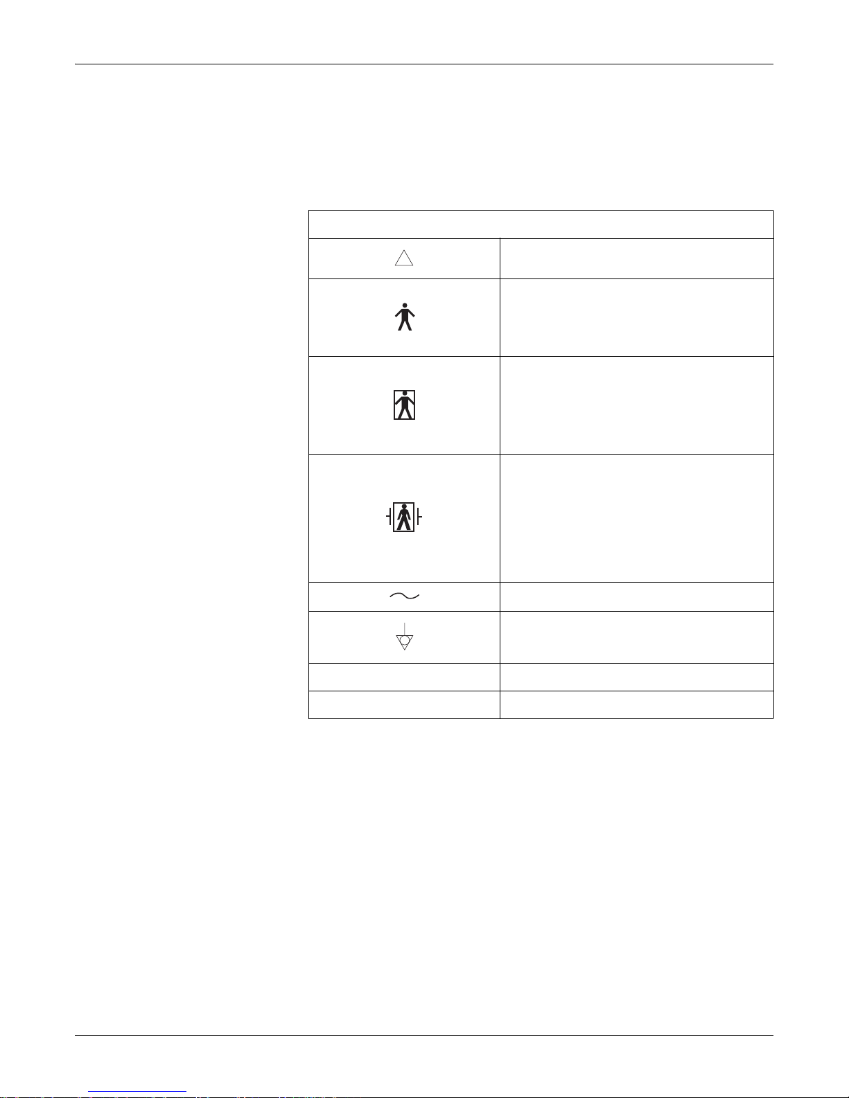
Table 1-2. Equipment Symbols
!
ATTENTION: Consult accompanying documents.
TYPE B EQUIPMENT. Type B equipment is
suitable for intentional external and internal
application to the patient, excluding direct cardiac
application.
TYPE BF EQUIPMENT.
suitable for intentional external and internal
application to the patient, excluding direct cardiac
application. Type BF equipment has an F-type
applied part.
DEFIBRILLATOR-PROOF TYPE BF EQUIPMENT:
Type BF equipment is suitable for intentional
external and internal application to the patient,
excluding direct cardiac application. Type BF
equipment is type B equipment with an F-type
isolated (floating) part. The paddles indicate the
equipment is defibrillator proof.
ALTERNATING CURRENT (AC).
EQUIPOTENTIALITY.
Type BF equipment is
Revision B 120 Series Maternal/Fetal Monitor 1-9
O POWER OFF: disconnection from the mains.
I POWER ON: connection to the mains.
2015590-001
Page 30

For your notes
Safety: Equipment Symbols
1-10 120 Series Maternal/Fetal Monitor Revision B
2015590-001
Page 31

Chapter 2
Introduction 2
This section lists the indications for use for maternal/fetal monitors in the
Corometrics 120 Series. The Corometrics 120 Series is extremely flexible, allowing
you to mix and match features.
This section provides information about your monitor in relation to this manual , as
well as the intended uses of the device:
Indications for Use . . . . . . . . . . . . . . . . . . . . . . . . . . . . . . . . . . . . . . . 2-2
Series Overview . . . . . . . . . . . . . . . . . . . . . . . . . . . . . . . . . . . . . . . . . 2-3
About the Manual. . . . . . . . . . . . . . . . . . . . . . . . . . . . . . . . . . . . . . . . 2-7
Revision B 120 Series Maternal/Fetal Monitor 2-1
2015590-001
Page 32

Indications for Use
Fetal Monitoring
A Corometrics 120 Series Monitor can be used for routine non-invasive and
invasive fetal monitoring throughout labor and delivery (i.e. fetal heart rate and
uterine activity monitoring) Fetal movement detection and fetal heart rate alarm
options (user selectable high/low and poor signal quality alarms) are available.
Maternal Monitoring
A Corometrics Model 128 or 129 Maternal/Fetal Monitor is intended for monitoring
maternal vital signs to help assess maternal well-being. The vital signs which can be
measured with either of these monitors are summarized below.
Introduction: Indications for Use
IMPORTANT– Maternal vital signs provided by the monitor
should only be used as an adjunct to patient assessment and must
be used in conjunction with clinical signs and symptoms.
Blood Pressure
Pulse Oximetry
Heart/Pulse Rate
NOTE: A Model 128 provides
maternal pulse rate data derived from
the NBP and MSpO
monitor. Only a Model 129 provides
both maternal heart rate and maternal
pulse rate data; the heart rate data is
derived from the MECG section of the
monitor while the pulse rate data is
derived from the NBP and MSpO
sections of the monitor.
2 sections of the
2
This parameter is intended for use in the non-invasive monitoring of maternal blood
pressure (NBP). This monitor is not intended for use in neonatal or pediatric blood
pressure monitoring.
This parameter is intended for use in the non-invasive monitoring of the functional
oxygen saturation of maternal arterial blood (MSpO
This parameter is intended for use in the non-invasive monitoring of the maternal
heart/pulse rate (MHR/P).
2).
2-2 120 Series Maternal/Fetal Monitor Revision B
2015590-001
Page 33

Series Overview
The Model 126 Monitor
Introduction: Series Overview
The Model 126 Monitor provides standard fetal monitoring parameters—dual
ultrasound, fetal ECG, and uterine activity. The Model 126 has the following
features:
Dual ultrasonic heart rate monitoring allows for non-invasive monitoring of
twins.
A +20 BPM heart rate offset option is provided for the secondary heart rate
(HR2) trend, when using dual ultrasound, or ultrasound and direct FECG, to
separate overlapping FHR trends for easy interpretation.
A heartbeat coincidence detection feature can be enabled to inform you when
there is the possibility that you may be monitoring a duplicate signal.
The electroluminescent (EL) display, with circularly polarized filter, removes
glare; its wide viewing angle provides easy viewing at a distance.
The strip chart recorder is a quiet, easy-to-load, high-resolution thermal array
printer. The recorder prints continuous trends and alphanumeric data on one
strip chart.
User-selectable font size for strip chart annotations customizes readability.
Automatic mode selection is provided simply by inserting the appropriate
transducer plug into the front panel receptacle.
The ChartLight allows the room lights to be dimmed without sacrificing
visibility of the strip chart recorder.
Transducer connectors are easy-to-use, color-coded, and durable.
Frequently used functions are controlled by your choice of front panel monitor
buttons—audio volume, UA reference, alarm silence, event mark, record, and
paper advance.
System setup options are easily accessed via a front panel Trim Knob control.
Fetal parameters are continuously displayed even during configuration of
system setup options.
Annotations from an optional Model 2116B Keyboard are printed on the strip
chart recorder paper.
The ultrasound mode provides clean accurate traces with few “dropouts”
because of Corometrics’ patented autocorrelation processing.
Fetal heart rate alarm limits are user-defined, with pre-set defaults. Signal
quality has no user-defined parameters.
Alarm limits are easily configured via setup screens.
Alarm silencing is controlled by a front panel monitor button which is brightly
colored for easy recognition.
Revision B 120 Series Maternal/Fetal Monitor 2-3
2015590-001
Page 34

Introduction: Series Overview
Alarm conditions have audible and visual indications. Audible alarms can be
disabled. Fetal heart rate threshold and signal quality alarms can be cancelled.
The monitor can be interfaced to the most widely used non-invasive blood
pressure monitors and pulse oximeters.
The FECG waveform can be optionally displayed and can be “frozen” on the
screen for review. In addition, a six-second “snapshot” can be printed on the
strip chart paper.
2-4 120 Series Maternal/Fetal Monitor Revision B
2015590-001
Page 35

The Model 128 Monitor
Introduction: Series Overview
The Model 128 Monitor provides all of the features of the Model 126 Monitor with
the addition of integrated maternal pulse oximetry and non-invasive blood pressure
monitoring, plus the following:
Built-in maternal vital signs monitoring eliminates the need for separate blood
pressure and maternal pulse oximetry monitors.
Maternal non-invasive blood pressure
*
readings can be taken on-demand or at
pre-programmed intervals using the well-known DINAMAP blood pressure
technology.
Smart BP option prevents blood pressure readings from occurring during
contractions.
Continuous non-invasive MSpO2 oxygen saturation and maternal pulse rate can
be reliably monitored using the well-known Nellcor pulse oximetry brand.
Continuous display/printing of the maternal pulse rate trend can be enabled.
Maternal alarm limits are user-defined, with pre-set defaults.
The audible indicator for each maternal alarm can be temporarily silenced.
Maternal vital signs storage provides an eight-hour history of the maternal vital
signs in a spreadsheet format. The data can be displayed or printed on-demand.
A maternal-only recording mode is specifically designed for postpartum
monitoring of the mother.
The MSpO2 pulsatile waveform can be optionally displayed and can be
“frozen” on the screen for review. In addition, a six-second “snapshot” can be
printed on the strip chart paper.
Revision B 120 Series Maternal/Fetal Monitor 2-5
*
Blood pressure is not automatically activated. Manual blood pressure readings must be started via a
front panel monitor button or display button. Automatic readings must be initiated via a setup
window.
2015590-001
Page 36

The Model 129 Monitor
The Model 129 has all of the features of the Model 128, plus the following:
Built-in independent MECG monitoring is provided with selection of lead I, II,
Twins and maternal monitoring can be accomplished simultaneously using dual
The MECG waveform can be optionally displayed and can be “frozen” on the
The large display shows fetal parameters, maternal parameters, and one
Upgrading Your Monitor
The 120 Series family of monitors provides one solution for high-risk and low-risk
labors and deliveries. The 120 Series of monitors lets you start with a basic monitor
and add the extended and/or more advanced features later as your clinical needs
increase and your budget allows. Refer to Chapter 12, “Upgrading a 120 Series
Monitor” , for more information.
Introduction: Series Overview
or III.
ultrasound and MECG; or using ultrasound, FECG, and MECG.
screen for review . In addition, a six-second snapshot can be printed on the strip
chart paper.
waveform all at once.
Adding Fetal Movement Detection
Each monitor in the series can be upgraded to include fetal movement detection
(FMD). Contact your Service Representative for more information.
2-6 120 Series Maternal/Fetal Monitor Revision B
2015590-001
Page 37

About the Manual
Purpose
Introduction: About the Manual
This manual documents all possible parameters so that when you upgrade you will
not require any new documentation. The manual also provides an opportunity to
read about features you may not have to assist you with your upgrade decisions.
Some sections will not apply if your monitor is not equipped with MSpO
NBP, MECG, or FSpO
the 120 Series family of monitors.
2 monitoring capabilities. Table 2-1 provides a summary of
Table 2-1. Summary of Monitoring Modes
2, maternal
Intended Audience
Parameter
126 128 129
US
US2
FECG
TOCO
IUP
NBP
MSpO2
MECG
a
The F-Series adds FSpO2.
This manual is intended for trained service professionals.
999
999
999
999
999
120 Series
a
Model
99
99
9
Illustrations
Revision B 120 Series Maternal/Fetal Monitor 2-7
All illustrations are provided as examples only. Your monitor may not be equipped
with all of the features shown. In addition, unless explicitly stated, the screen
examples do not represent your equipment setup or displayed data.
2015590-001
Page 38

Introduction: About the Manual
Design Changes
Due to design changes associated with continuing product improvem ents,
information in this manual is subject to change. GE Medical Systems Information
Technologies reserves the right to change software/hardware design at any time and
any such changes could affect the contents of the manual. GE assumes no
responsibility for any errors or inconsistencies appearing in this manual that result
from product design changes and upgrades.
References to Persons, Places, and Institutions
References to persons, places, and institutions used within this manual are solely
intended to facilitate user comprehension of the 120 Series Monitor’s use and
functions. Extreme care has been taken to use fictitious names and related
information in the examples and illustrations provided herein. Any similarity of this
data to persons either living or dead and to either current or previously existing
medical institutions should be regarded as coincidental.
2-8 120 Series Maternal/Fetal Monitor Revision B
2015590-001
Page 39

Chapter 3
Controls, Indicators, and
Connectors
This section describes all possible controls, indicators, and connectors in the 120
Series of monitors.
The section contains the following:
Front Panel Description . . . . . . . . . . . . . . . . . . . . . . . . . . . . . . . . . . . 3-2
Front Panel Displays . . . . . . . . . . . . . . . . . . . . . . . . . . . . . . . . . . . . . 3-5
Rear Panel Description. . . . . . . . . . . . . . . . . . . . . . . . . . . . . . . . . . . 3-17
3
Revision B 120 Series Maternal/Fetal Monitor 3-1
2015590-001
Page 40

Controls, Indicators, and Connectors: Front Panel Description
Front Panel Description
Start/Stop
Test
BP
IJK
Mark
[Offset]
Reference
E
BCD
165
A
FSpO
NBP
130/ 85
MAP (107)
2
03:15
US2US
172
02:15
MECG
89
TOCO
MSP02
97%
30
25 mm/s
II
Volume Volume
2X
FGH
Alarm
Silence
M
N
L
Record
UA
Paper
Power
Advance
Trim
Knob
O
Y
03:22:45
FREEZE
PRINT ALARMS
US
US2 UA
!
W
X
V
SETUP
FECG/MECG
VSHX
MATERNAL
BP
SpO
2
U
S
T
4305CAO
bpm
150
180
210
240
FHR
306090
120
R
UA
kPa
8
0
426
12
10
P
Q
Figure 3-1. Model 129 Front Panel
3-2 120 Series Maternal/Fetal Monitor Revision B
2015590-001
Page 41

Controls, Indicators, and Connectors: Front Panel Description
Table 3-1. Model 129 Front Panel
# Name Description
The monitor’s display is divided into several sections. The content and layout of the
A Display
display can change, depending on which functions are installed in the monitor and the
modes of operation in use.
B FHR1 Volume Decrease Button
C FHR1 Volume Increase Button
D FHR2 Volume Decrease Button
The four Volume buttons raise ( ) and lower ( ) the volume of sound emitted by
the rear panel speaker. The left pair controls the volume for FHR1. The right pair
controls the volume for FHR2.
Volume settings have no effect on the processing used to determine heart rate. The
volume buttons work in conjunction with the volume control settings on the US/US2
E FHR2 Volume Increase Button
Setup screen (page 5-9) and on the FECG Setup screen (page 5-8).
F Alarm Silence Button Pressing this button removes the audible indication of an individual alarm.
G Test Button
H BP Start/Stop Button
Pressing and holding this button for one second starts or stops a monitor self-test
routine.
This button starts and stops both manual and automatic blood pressure
determinations. It also provides a “shortcut” for changing the auto interval time.
I UA Reference Button The UA Reference button sets a baseline for uterine activity pressure monitoring.
The Mark (Offset) pushbutton is a multi-function pushbutton.
Mark: Pressing this button prints an event mark on strip chart paper (on the
J Mark [Offset] Button
bottom two lines of the top grid).
Offset: When the Heart Rate Offset mode is enabled, pressing and holding this
button shifts the secondary FHR trend +20 BPM for visibility purposes.
K Paper Advance Button
Pressing this button advances chart paper at a rate of 40 cm/min for as long as the
button is held down.
L Record Button The Record button selects one of three recorder states: on, maternal-only mode, or off.
M Power Indicator The indicator lights green when the monitor is turned on.
N Record Indicator
O Trim Knob Control
P Recorder Door Latch Opens the strip chart recorder door to add, remove, or adjust the paper.
Q Power Switch
R Strip Chart Recorder
Revision B 120 Series Maternal/Fetal Monitor 3-3
Indicator Status Recorder Status
on on
off off
flickers maternal-only mode
flashing error condition
Operation of the monitor is controlled by using the front panel pushbuttons in
conjunction with the Trim Knob control. This control selects softkeys on the display
and positions a cursor within a setup screen. Rotate the Trim Knob control left or right
to highlight items on the screen with a bar cursor. After highlighting the desired item,
press the Trim Knob control to make the selection. In summary: rotate to move cursor;
press to select an item.
Moving the switch to the on position (I) turns on the monitor; moving the switch to the
off position (O) turns off the monitor.
Annotations and trends are printed on the strip chart paper. Two paper styles are
available. Refer to “Chapter 5, Setup Procedures” , for instructions on loading strip
chart paper into the recorder.
2015590-001
Page 42

Controls, Indicators, and Connectors: Front Panel Description
Table 3-1. Model 129 Front Panel
# Name Description
S Maternal NBP Connector
T Maternal SpO
2 Connector
Connect a pneumatic hose and blood pressure cuff assembly to this black twin lumen
receptacle.
Connect a 120 Series MSpO
2 intermediate cable to this royal blue receptacle. Use only
Nellcor cables if you have Nellcor technology installed and only Masimo cables if you
have Masimo technology installed in your monitor.
Connect an FECG or MECG cable plug to this green receptacle. For Models 126 or
U FECG or FECG/MECG Connector
128, the connector is labeled
MECG
.
Cables with rectangular plugs connect directly to the FECG/MECG receptacle. Cables
FECG. For a Model 129, the connector is labeled FECG/
with round plugs require an FECG/MECG adapter, cat. no. (REF) 1442AAO. Use this
adapter for dual ECG monitoring as well. The adapter branches into two cables, each
V UA Connector
with a round receptacle at the end: one branch is labeled
labeled
FECG.
Connect a tocotransducer, IUPC, or strain gauge transducer plug to this white
receptacle Contact your Sales Representative for information about compatibility.
MECG; the other branch is
W US2 Connector Connect the secondary ultrasound transduc er plug to this light gray receptacle.
X US Connector Connect the primary ultrasound transducer plug to this light gray receptacle.
YFetal SpO
2 Connector
Connect a 120 Series Fetal Patient Module cable to this light blue receptacle. Use only
Nellcor OxiFirst Fetal Oxygen Sensors (Series FS14).
3-4 120 Series Maternal/Fetal Monitor Revision B
2015590-001
Page 43

Controls, Indicators, and Connectors: Front Panel Displays
Front Panel Displays
The monitor’s display is divided into five horizontal sections. The content and
layout of the display can change, depending on which functions are installed in the
monitor and the modes of operation in use.
Display Section Item Mode
Fetal Heart Rate 1 (FHR1) US, US2, FECG, or INOP
Table 3-2. Display Summary
Primary Labor Parameters
Fetal Heart Rate 2 (FHR2) US, US2, or INOP
Uterine Activity (UA) TOCO, IUP, or INOP
Maternal Blood Pressure NBP
Additional Parameters
Waveform
Time
Maternal Heart/Pulse Rate MECG or PULSE
Fetal or Maternal SpO
Fetal ECG Waveform; Maternal ECG Waveform; Fetal
SpO2 Pulsatile Waveform; or Maternal SpO2 Pulsatile
Waveform
2 %FSpO2 or %MSpO2
FECG, MECG, FSpO2, MSpO2, or
OFF
Current Time; [LABEL] FROZEN Message, and Time of
Activation
Softkeys System Configuration Softkey Controls —
Display Example
Figure 3-2, “Model 129 Display Example,” on page 3-6, provides an example of a
Model 129 display. In this example:
Blood pressure is not active as indicated by the absence of numerics.
Maternal pulse oximetry is active.
MECG is selected as the heart rates source as indicated by the MECG mode title
softkey—rather than
The MECG waveform is displayed at 25 mm/sec, at a size of 2X, with lead II
selected.
Heartbeat coincidence is enabled as indicated by the HBC acronym in the
primary labor parameters area.
All alarms are enabled as indicated by .
PULSE.
—
Revision B 120 Series Maternal/Fetal Monitor 3-5
2015590-001
Page 44

Controls, Indicators, and Connectors: Front Panel Displays
FECG
165
NBP MECG
US
172 30
87
MECG
PRINT FREEZE ALARMS SETUP
Figure 3-2. Model 129 Display Example
HBC
MSpO
98%
TOCO
2
25 mm/s
II 2X
15:52:58
VSHX
The Model 126 has a unique feature which automatically centers the primary fetal
parameters in the display when no waveform is active. See figure below.
FECG
165
OFF
Figure 3-3. Model 126 Display
US
172
ALARMS SETUP
TOCO
30
15:50:27
VSHX
3-6 120 Series Maternal/Fetal Monitor Revision B
2015590-001
Page 45

Controls, Indicators, and Connectors: Front Panel Displays
Primary Labor Parameters
The primary labor parameters section displays FHR1, FHR2, and UA data.
FHR Display
The FHR1 and FHR 2 areas are summarized by Figure 3-4 and
Table 3-3.
A FHR Value
FHR Alarm Setting
B
Indicator
C
B
FECG
A
165
Figure 3-4. FHR Display
Table 3-3. FHR Display
Name Description
Up to three digits indicate the fetal heart rate in
beats per minute.
This symbol provides information about the FHR
audio alarm and the FHR high/low alarm limit
settings.
: An alarm setting is turned off.
D
Revision B 120 Series Maternal/Fetal Monitor 3-7
: All alarm settings are enabled.
An abbreviation indicates the monitoring mode in
FECG, US, US2, or INOP. (FECG only displays
use:
C FHR Mode Title
D FHR Heartbeat Indicator Flashes with each detected valid heartbeat.
2015590-001
in the FHR1 area.) Select the mode softkey to
access the respective setup screen. See Table 3-4
for FHR connection options.
Page 46

Controls, Indicators, and Connectors: Front Panel Displays
Table 3-4. Connectors vs. Display Modes
Active Connectors
FECG
FECG/US
FECG/US2
US
US/US2
US2
—
FECG/US/US2
a
If three FHR transducers are plugged in, the FECG signal overrides the US signal.
a
FHR1 Area FHR2 Area
FECG INOP
FECG US
FECG US2
US INOP
US US2
US2 INOP
INOP INOP
FECG US2
3-8 120 Series Maternal/Fetal Monitor Revision B
2015590-001
Page 47

Controls, Indicators, and Connectors: Front Panel Displays
UA Display
The UA area is summarized by Figure 3-5 and Table 3-5.
B
TOCO
A
30
Figure 3-5. UA Display
Table 3-5. UA Display
Name Description
A UA Value
B UA Mode Title
Up to three digits indicate the uterine activity
value—mmHg for internal monitoring or relative
units for external monitoring.
An abbreviation indicates the monitoring mode in
use:
TOCO, IUP, or INOP.
Revision B 120 Series Maternal/Fetal Monitor 3-9
2015590-001
Page 48

Additional Parameters
Controls, Indicators, and Connectors: Front Panel Displays
The additional parameters area displays NBP, MHR/P, and MSpO2 data.
Maternal NBP
The maternal NBP section is summarized by Figure 3-6 and Table 3-6.
C
B
130/ 85
A
Name Description
A NBP Time Stamp
D
NBP
E
11:41
MAP (107)
03:15
Figure 3-6. NBP Display
Table 3-6. NBP Display
The time (in 24-hour format) of the last blood
pressure measurement.
B NBP Values
NBP Alarm Setting
C
Indicator
D NBP Mode Title
E NBP Countdown Timer
The systolic/diastolic and mean arterial pressures
(MAP) are each indicated by up to three digits—
representing mmHg.
During a determination, the instantaneous cuff
pressure displays in place of the mean arterial
pressure and is denoted by the title
This symbol provides information about the NBP
audio alarm and the NBP high/low alarm limit
settings.
: An alarm setting is turned off.
: All alarm settings are enabled.
Select the mode title to access the NBP Setup
screen.
The clock symbol represents activation of the auto
mode. The countdown timer indicates the minutes
and seconds until the next automatic reading.
CUFF.
3-10 120 Series Maternal/Fetal Monitor Revision B
2015590-001
Page 49

Controls, Indicators, and Connectors: Front Panel Displays
MHR/P Area
The MHR/P area is summarized by Figure 3-7 and Table 3-7.
B
A
Name Description
A MHR/P Value
MHR/P Alarm Setting
B
Indicator
C
D
MECG
89
Figure 3-7. MHR/P Display
Table 3-7. MHR/P Display
Up to three-digits indicate the MHR/P in beats per
minute.
This symbol provides information about the MHR/P
audio alarm and the MHR/P high/low alarm limit
settings.
: An alarm setting is turned off.
C MHR/P Mode Title
Maternal Heartbeat
D
Indicator
: All alarm settings are enabled.
The mode title
P source; the mode title
NBP is used as the source. Select the mode title
softkey to access the MHR/P Setup screen.
Flashes with each detected valid heartbeat—for
MECG only.
MECG indicates MECG is the MHR/
PULSE indicates MSpO2 or
Revision B 120 Series Maternal/Fetal Monitor 3-11
2015590-001
Page 50

Controls, Indicators, and Connectors: Front Panel Displays
FSpO2 Area
The FSpO2 area is summarized by Figure 3-8 and Table 3-8.
IMPORTANT
If FSpO
the Additional Parameters Area. When dual SpO
occurs, FSpO
beneath the MSpO2 area.
2 is monitored while MSpO2 is inactive, FSpO2 displays in
2 information is displayed in the Waveform Area
C
B
2 monitoring
D
A
Figure 3-8. FSpO
Table 3-8. FSpO
Name Description
A FSpO
B FSpO
2 Value
2 Mode Title
C Signal Quality Indicator
2 Display
2 Display
This three-digit display indicates the FSpO
2 level
calculated form qualified optical pulses.
The
FSpO2 title indicates that fetal oxygen
saturation monitoring is in progress.
This indicator shows the average signal quality of
pulses being detected at the sensor site according
to a software algorithm in the 120 F-Series Monitor.
The presence of all ten bars represents fetal pulses
with consistently high signal quality for FSpO
2
measurement. Fewer bars represents diminished
signal quality. The absence of bars represents a
lack of fetal pulses with acceptable signal quality.
3-12 120 Series Maternal/Fetal Monitor Revision B
D
Pulse Amplitude
Indicator
2015590-001
This vertical bar qualitatively indicates pulse
amplitude at the sensor site.
Page 51

Controls, Indicators, and Connectors: Front Panel Displays
MSpO2 Area
The MSpO2 area is summarized by Figure 3-9 and Table 3-9.
B
A
A MSpO
MSpO
B
Indicator
C
Figure 3-9. MSpO
Table 3-9. MSpO
2 Display
2 Display
Name Description
2 Value
Up to three digits indicate the percentage of
oxygen in the mother’s blood.
This symbol provides information about the MSpO
audio alarm and the MSpO
2 Alarm Setting
settings.
: An alarm setting is turned off.
D
2
2 high/low alarm limit
: All alarm settings are enabled.
C MSpO
MSpO
D
Indicator
2 Mode Title
2 Pulse Amplitude
Select the mode title to access the MSpO
screen.
This vertical bar qualitatively indicates pulse
amplitude.
2 Setup
Waveform Area
The waveform area displays approximately four seconds of waveform data for:
FECG, MECG, FSpO
2 or MSpO2.
Time and Waveform Message Area
The current time (in 24-hour format) always displays on the far right. When a
waveform is frozen, the message [
the time of activation.
LABEL] FROZEN displays on the far left, along with
Revision B 120 Series Maternal/Fetal Monitor 3-13
2015590-001
Page 52

Controls, Indicators, and Connectors: Front Panel Displays
Battery-Backed RAM Status
Whenever you turn off a 120 Series Monitor, a battery provides power to the RAM
(random access memory) that stores information such as time, date, default settings,
etc.
Figure 3-10. Low Battery Icon
The icon shown above will appear in the upper right-hand section of the monitor
under the following circumstances.
Table 3-10. Battery-Backed RAM Status
Icon Appearance Reason Solution
Icon appears and then
disappears after power
cycle.
Icon appears after
multiple power cycles.
Softkeys
Data corruption. Your monitor has reverted to
factory settings.
Battery requires service. Call GE Service to report.
A softkey is an area on the screen that can be selected with the Trim Knob control.
When the softkey is activated by pressing the Trim Knob control, it may cycle
through available settings or it may display a setup screen.
Access setup screens and configure last-used
settings.
Mode Title Softkeys
Most of the mode titles in the display are also softkeys which give access to
corresponding setup screens:
US, US2, FECG, NBP, MECG, PULSE, FSPO2 and MSPO2.
Waveform Softkeys
The waveform title is a softkey used to select the waveform for display or to disable
the area, The ECG scale and MECG lead labels are softkeys used to configure the
waveform currently displayed.
3-14 120 Series Maternal/Fetal Monitor Revision B
Dedicated Softkey Area
Softkeys are located at the bottom of each screen, as shown in Figure 3-11 and
Figure 3-12. Although there are many possible softkeys which may appear in this
area, a maximum of five are shown at a time.
2015590-001
Page 53

Controls, Indicators, and Connectors: Front Panel Displays
US
165
NBP
130/ 85
MAP (107)
03:15
I
MECG 09:21:41 ECG FROZEN
PRINT FREEZE ALARMS SETUP VSHX
H
02:15
G
US2
172
MECG
89
F
HBC
MSPO2
97%
E
TOCO
30
25 mm/s
II AUTO
09:22:06
D
A
B
C
Figure 3-11. Display Summary
Table 3-11. Display Summary
Name Description
A Mode Title Softkeys
B ECG Scale Softkey Selects 0.25X, 0.5X, 1X, 2X, 4X, or AUTO.
MECG Lead Select
C
Softkey
D VSHX Softkey Displays maternal Vital Signs History screen.
E SETUP Softkey Displays General Setup screen
F ALARMS Softkey Displays Master Alarm Setup screen.
G FREEZE Softkey
H PRINT Softkey
Selects US, US2, FECG, NBP, MHR/P, or SpO
Setup screens.
Selects Lead I, II, or III.
Freezes waveform for analysis; unfreezes
waveform to return to real-time display.
Prints six-second snapshot of frozen waveform,
real-time waveform, or maternal vital signs history.
2
Revision B 120 Series Maternal/Fetal Monitor 3-15
I Waveform Softkey Selects FECG, MECG, FSpO
2015590-001
2, MSpO2, or OFF.
Page 54

Controls, Indicators, and Connectors: Front Panel Displays
Figure 3-12. Maternal Vital Signs History Screen Softkeys
DCBA
Table 3-12. Maternal Vital Signs History Screen Softkeys
Name Description
A PRINT Softkey Prints one page (screen) of the table.
B PRINTALL Softkey Prints all pages (screens).
Scrolls through the data:
C VIEW Softkey
Left for recent data
Right for oldest data
D EXIT Softkey Returns to the previous screen.
3-16 120 Series Maternal/Fetal Monitor Revision B
2015590-001
Page 55

Controls, Indicators, and Connectors: Rear Panel Description
Rear Panel Description
F
Figure 3-13. 120 Series Rear Panel Connectors (Standard and Optional)
Revision B 120 Series Maternal/Fetal Monitor 3-17
IMPORTANT––The fetal acoustic stimulator connector (J) and
the remote event marker (K) connector are identical in size. To
ensure data accuracy, be sure to plug sensors into the correct
connectors.
2015590-001
Page 56

Controls, Indicators, and Connectors: Rear Panel Description
Table 3-13. 120 Series Rear Panel (Standard and Optional Features)
Name Description
A Vent
J101 Telemetry
B
Connector
J103 Data Entry
C
Connector
J104 Nurse Call
D
Connector
J102 Central Systems
E
Connector
F Speaker
G J108 Corolan Connector
Provides ventilation for the monitor’s internal
circuitry.
Connector for Corometrics telemetry system
interface. (Installed as part of an optional
communications package.)
Connector for data entry system interface.
(Installed as part of an optional communications
package.)
Connector for standard Nurse Call System
interface. The connector’s maximum output is 50
Vdc at 100 mA; the maximum on resistance is
0.5 Ω. (Installed as part of an optional
communications package.)
Connector for analog central station system
interface. (Installed as part of an optional
communications package.)
The rear panel speaker emits an audible tone for
heart rates, MSpO
2 pulse with %O2-dependent
pitch, and alarms. It also provides the sound for
the song player feature.
This 25-pin connector is used for interfacing to
optional Corometrics equipment. Contact your
Service Representative for more information.
3-18 120 Series Maternal/Fetal Monitor Revision B
J109, J110, and J111
RS-232C
H
Communications
Connectors
I ECG Out Connector
Fetal Acoustic
J
Stimulator Connector
Remote Event Marker
K
Connector
2015590-001
Three serial RJ-11 connectors are provided for
interfacing to peripheral equipment. Contact your
Service Representative for more information.
External recorder receptacle for MECG signals.
The standard output level is 1 V/mV.
Receptacle for Corometrics Model 146 Fetal
Acoustic Stimulator (FAST). A music symbol prints
on the strip chart paper each time the Model 146 is
used:
Receptacle for the Corometrics Remote Event
Marker. When activated, one of the following
marks prints on the strip chart paper:
The event marker is commonly used to record
an “event”:
The fetal movement marker (default setting) is
commonly used as an indication that the mother
has perceived fetal movement:
FM
Page 57

Controls, Indicators, and Connectors: Rear Panel Description
Table 3-13. 120 Series Rear Panel (Standard and Optional Features)
Name Description
NOTE: Although the J104 Nurse
Call connector is physically present
on the optional communications
package, this connector is only
supported as part of the Spectra
Alerts option.
L Equipotential Lug
A binding post terminal is directly connected to the
chassis for use as an equipotentiality connection.
This switch is intended for qualified service
personnel to select a voltage range for the AC
AC Voltage Selection
M
Switch
input:
120: Accepts an AC input in the range of 100–
120 VAC.
240: Accepts an AC input in the range of 220–
240 VAC
AC line power cord receptacle. Refer to the rear
N Power Entry Module
panel markings to verify line voltage and line
frequency requirements.
CAUTION
NON-DESTRUCTIVE VOLTAGE—The maximum nondestructive voltage that may be applied to the rear panel
connectors is 0 volts. Do not attempt to connect cables to these
connectors without contacting your Biomedical Engineering
Department or Information Technolo gies Service Representative.
This is to ensure the connectors comply with leakage-current
requirements of one of the following applicable standards:
Underwriters Laboratories UL-2601.1, Canadian Standards
Associations CSA 22.2 No. 125, or International Electrotechnical
Commission EN60601.1.
Revision B 120 Series Maternal/Fetal Monitor 3-19
2015590-001
Page 58

Controls, Indicators, and Connectors: Rear Panel Description
Communication Option
The communication option is an additional circuit board that can be installed in the
120 Series Monitor. Refer to “Chapter 12, Upgrading a 120 Series Monitor” , for
upgrade information. The following four connectors are part of the optional
communications package: J101, J102, J103, and J104.
J101 Connector
This high-density 15-pin connector is intended for interfacing to the receiver of a
Corometrics 340 Series Telemetry System.
J102 Connector
This Centronics-type connector is used for interfacing to a central station system
such as a Corometrics Spectra 400 Surveillance and Alert System. (This connector is
often referred to as the Analog Interface Connector.)
J103 Connector
This 15-pin connector is used for attaching to an optional data entry system.
J104 Connector
Corolan Option
This connector attaches to a standard Nurse Call System. The connector’s maximum
output is 50 Vdc at 100 mA; the maximum on resistance is 0.5 Ω. When connected
to a Nurse Call System, the monitor will activate the system each time a Spectra
Alert is issued. This interface simulates pressing the button on a bedside Nurse Call
System allowing nurses to respond to patient needs quickly and efficiently.
NOTE: Although the J104 Nurse Call connector is physically present on the
optional communications package, this connector is only supported as part
of the Spectra Alerts option.
J108 is installed as part of a Corolan Option. Refer to “Chapter 12, Upgrading a 120
Series Monitor” for upgrade information.
3-20 120 Series Maternal/Fetal Monitor Revision B
2015590-001
Page 59

Chapter 4
Theory of Operation 4
This section of the manual contains the electronic theory of operation for the 120
Series Monitor. For parts information, refer to “Chapter 14, Replacement Parts”.
This chapter contains the following information:
Main Motherboard . . . . . . . . . . . . . . . . . . . . . . . . . . . . . . . . . . . . . . . 4-2
DSP Board . . . . . . . . . . . . . . . . . . . . . . . . . . . . . . . . . . . . . . . . . . . . 4-24
NBP Board . . . . . . . . . . . . . . . . . . . . . . . . . . . . . . . . . . . . . . . . . . . . 4-35
Communications Board . . . . . . . . . . . . . . . . . . . . . . . . . . . . . . . . . . 4-39
System Power Supply. . . . . . . . . . . . . . . . . . . . . . . . . . . . . . . . . . . . 4-44
Display Board. . . . . . . . . . . . . . . . . . . . . . . . . . . . . . . . . . . . . . . . . . 4-45
Dual Ultrasound Board. . . . . . . . . . . . . . . . . . . . . . . . . . . . . . . . . . . 4-46
UA/FECG Board . . . . . . . . . . . . . . . . . . . . . . . . . . . . . . . . . . . . . . . 4-52
MECG Board . . . . . . . . . . . . . . . . . . . . . . . . . . . . . . . . . . . . . . . . . . 4-61
Oximeter Carrier Board . . . . . . . . . . . . . . . . . . . . . . . . . . . . . . . . . . 4-70
MSpO2 Board . . . . . . . . . . . . . . . . . . . . . . . . . . . . . . . . . . . . . . . . . 4-71
Isolated Power Supply Board. . . . . . . . . . . . . . . . . . . . . . . . . . . . . . 4-76
Recorder Board . . . . . . . . . . . . . . . . . . . . . . . . . . . . . . . . . . . . . . . . 4-82
Revision B 120 Series Maternal/Fetal Monitor 4-1
2015590-001
Page 60

Main Motherboard
NOTE: Main Motherboard 2000608-003 (with software version 2.0) replaces
Functional Overview
The Main Motherboard makes up the central processing unit of the 120 Monitor.
The Main Motherboard accepts simultaneously processed parameters directly from
four separate modules. A Model 126 Monitor has the DSP Board as its only input
module. Heart rate data, uterine activity data, mode information, and FMD data flow
from the DSP Board to the Main Motherboard via shared memory. Maternal and
fetal pulse oximetry make up the second and third modules. Information from these
devices is passed to the Main Motherboard via internal RS-232C ports. Maternal
blood pressure makes up the fourth module which also passes data via an internal
RS-232C port. Figure 4-1 shows the data flow.
Theory of Operation: Main Motherboard
earlier version 11619 Boards. If you update an older monitor (11619 Main
Board and 3-inch x 3.75-inch display) with a new Main board, which is
factory-set for the new larger display (3.5-inch x 4.5-inch display), the
Main screen will have space below the bottom row of softkeys. Use the
Flasher Software Utility Kit, to re-configure the monitor software to
operate with the installed smaller display. Refer to “Display Upgrade” on
page 12-40 and “Upgrading to a 3.5” x 4.5” Display” on page 7-11 for
more information.
Switch/Status Input Data Flow Diagram
The Main Motherboard also processes information coming in from buttons and
sensors. Information from the front panel switches comes from the DSP Board
(passed through the main microprocessor). Status information comes from the
Recorder Board and the Communications Board interface. Figure 4-2 provides a
summary.
External/Internal Communication Data Flow
The Main Motherboard handles all internal and external data communications. Four
external communication interfaces are present. For the Corolan interface, monitor
data flows predominantly from monitor to master. Three external RS-232C
communication interfaces are set up predominantly to receive data from external
parameter monitors such as fetal pulse oximeters, maternal pulse oximeters, and
maternal blood pressure monitors. Internal communications consists of three
channels of RS-232C for NBP, MSpO
of the communication data flow.
2, and FSpO2. Figure 4-3 provides a summary
Audio Control Flow
Another function of the Main Motherboard is to control the audio from various
sources. Pure audio (non-processor generated) information comes from the
Ultrasound Board (US and US2) only. The remaining sources of audio are generated
by the processor through the use of timers and the host processor. Timer sources of
audio are initiated by the FECG, NBP, MSpO
2, and DSP internal modules. Audio
4-2 120 Series Maternal/Fetal Monitor Revision B
2015590-001
Page 61

Theory of Operation: Main Motherboard
from the host processor is summed into the main audio and is not controlled by the
main processor. Figure 4-4 provides a summary of the audio control flow.
Main Motherboard
Figure 4-1. Main Motherboard Input Parameter Data Flow
RS-232C
RS-232C
Shared
Memory
RS-232C
Switches
MSpO2 Module
NBP Module
DSP Board
2 Module
FSpO
DSP / Switch
Interface Board
Dual Ultrasound
UA/FECG
MECG
Front Panel
Main Motherboard
Switches
Switches
Rear Panel Module
Recorder Board
Figure 4-2. Main Motherboard Switch Input Data Flow
Revision B 120 Series Maternal/Fetal Monitor 4-3
2015590-001
Page 62

External QS
Central System
External RS-232C
MSpO
2 Monitor
External RS-232C
NBP Monitor
External RS-232C
(reserved for future use)
Figure 4-3. Main Motherboard Communications Data Flow
From Host Processor
Theory of Operation: Main Motherboard
NBP
Corolan
2
MSpO
Data
NBP
Data
Parameter
Data
Main Motherboard
Data
MSpO
Data
Parameter
Data
Internal RS-232C
2
Internal RS-232C
MSpO
Internal RS-232C
Future Module
NBP Module
2 Module
Timer 1
Timer 2
ECG Timer
US1
US2
Volume Controls
Figure 4-4. Main Motherboard Audio Control Flow
Audio Mixer
and
Filters
Audio
Amplifier
4-4 120 Series Maternal/Fetal Monitor Revision B
2015590-001
Page 63

Theory of Operation: Main Motherboard
Table 4-1. Main Power Connector
Pin Number Signal Name Signal Description
1 AGND Analog Ground
2 GND Digital Ground
3 GND Digital Ground
4 GND Digital Ground
5 +5V +5V Logic Supply
6 +5V +5V Logic Supply
7 +5V +5V Logic Supply
8 GNDAUD Audio Ground for +12 V
9 GNDBP NBP and Isolated Supply Ground
10 +15BP Supply for NBP
11 +12AUD Supply for Audio
12 +12EL Supply for EL panel
13 GNDEL Ground for EL panel
14 +20I 20 V for Isolated Power Supply
15 GNDI Ground for Isolated Power Supplies
16 +15US +15 V for Ultrasound
17 –15V –15 V for Ultrasound
18 72KHZ Power Supply Sync Frequency from US Board
Revision B 120 Series Maternal/Fetal Monitor 4-5
2015590-001
Page 64

Theory of Operation: Main Motherboard
.
Table 4-2. RS-232 Connectors J11 and J13
Pin Number Signal Name Signal Description
1 RTS Request to Send Output from Monitor
2 RXD Receive Data Input to Monitor
3 GND Signal Ground
4 GND Frame Ground
5 TXD Transmit Data Output from Monitor
6 CTS Clear to Send Input to Monitor
Table 4-3. RS-232 Connector J12
Pin Number Signal Name Signal Description
1 RTS Always Inactive
2 RXD Receive Data Input to Monitor
3 GND Signal Ground
4 GND Frame Ground
5 TXD Transmit Data Output from Monitor
6 No connection —
4-6 120 Series Maternal/Fetal Monitor Revision B
2015590-001
Page 65

Theory of Operation: Main Motherboard
Table 4-4. Corolan Connector J2
Pin Number Signal Name Signal Description
1 No connection —
2 GND Ground
3 ADR0 Junction Box Address Line Input
4 ADR1 Junction Box Address Line Input
5 ADR2 Junction Box Address Line Input
6 ADR3 Junction Box Address Line Input
7 ADR4 Junction Box Address Line Input
8 ADR5 Junction Box Address Line Input
9 LED Junction Box LED Control Line
10 No connection —
11 No connection —
12 No connection —
13 SIGNAL GND Signal Ground
14 No connection —
15 No connection —
16 No connection —
17 No connection —
18 No connection —
19 CENTER COAX Corolan Center Coax
20 SHIELD COAX Corolan Shield Coax
21 No connection —
22 No connection —
23 No connection —
24 No connection —
25 No connection —
Revision B 120 Series Maternal/Fetal Monitor 4-7
2015590-001
Page 66

Theory of Operation: Main Motherboard
Table 4-5. DSP Board Connector J7
Signal Type
Pin Number Signal Name
(Relative To Main
Signal Description
Motherboard)
1 IRQ7/ Input Interrupt Line from DSP Board Shared RAM
2 SHEM/ Output DSP Shared Memory Chip Select Line
3 No Connection — —
4 RESA02 Output Reset Line for SpO
2 Module
5 RESDSP/ Output Processor Controlled Reset Line
6 72kHz Input 72 kHz from Front End to Sync Power Supplies
7 +15v Output +15 Volt Analog Supply
8 –15V Output –15 Volt Analog Supply
9 AGND Output Analog Ground
10 AGND Output Analog Ground
11 –15v Output –15 Volt Analog Supply
12 AGND Output Analog Ground
13 US2AUDIO Input Ultrasound2 Audio
14 GND Output Digital Ground
15 TMECG Output Telemetry MECG
16 TELMAUDIO Input Telemetry Audio
17 IRQ7/(alt) Input
Alternate Interrupt from DSP Board (Jumper Selectable
On to Processor IRQ7/ Line)
18 D0B I/O Buffered Data Line
19 D2B I/O Buffered Data Line
20 D4B I/O Buffered Data Line
21 D6B I/O Buffered data line
22 D8B I/O Buffered data line
23 D10B I/O Buffered data line
24 +5V Output +5 Volt Logic Supply
25 D12B I/O Buffered Data Line
26 D14B I/O Buffered Data Line
27 A1B Output Buffered Address Line
28 A3B Output Buffered Address Line
4-8 120 Series Maternal/Fetal Monitor Revision B
2015590-001
Page 67

Theory of Operation: Main Motherboard
Table 4-5. DSP Board Connector J7 (Continued)
Signal Type
Pin Number Signal Name
(Relative To Main
Signal Description
Motherboard)
29 A5B Output Buffered Address Line
30 A7B Output Buffered Address Line
31 GND Output +5 Volt Power Ground Return
32 A9B Output Buffered Address Line
33 A11B Output Buffered Address Line
34 A13B Output Buffered Address Line
35 A15B Output Buffered Address Line
36 SP2B/ Output Spare Chip Select Line
37 SP4B/ Output Spare Chip Select Line
38 +5V Output +5 Volt Logic Supply
39 UDSB/ Output Buffered Upper Data Strobe
40 +5V Output +5 Volt Logic Supply
41 GNDI Output 20 V Ground
42 GNDI Output 20 V Ground
43 IRQ6/ Input Processor Interrupt Line
44 +20I Output +20 Volt Supply
45 +20I Output +20 Volt Supply
46 GND Output Digital Ground
47 GND Output Digital Ground
48 GND Output Digital Ground
49 GNDEL Output Ground Return
50 GNDEL Output Digital Ground
51 RXDC Input Main Bd. RXD Line for MSpO
52 TXDB Output Main Bd. TXD Line for FSpO
53 TXDC Output Main Bd TXD Line for MSpO
2 Module
2 Module
2 Module
54 RTSC Output Main Bd. RTS Line for MSpO
55 RXDB Input Main Bd. RXD Line for FSpO
56 +15us Output +15 Volts for Ultrasound
57 AGND Output Analog Ground
58 +15v Output +15 Volts Analog Supply
Revision B 120 Series Maternal/Fetal Monitor 4-9
2 Module
2 Module
2015590-001
Page 68

Theory of Operation: Main Motherboard
Table 4-5. DSP Board Connector J7 (Continued)
Signal Type
Pin Number Signal Name
(Relative To Main
Signal Description
Motherboard)
59 FECG 80db Input FECG Analog for Rear Panel Output
60 AGND Output Analog Ground
61 US1audio Input Ultrasound Channel One Audio
62 MECG 60db Input MECG Analog for Rear Panel
63 PACER/ Input Pacemaker Detect Line
64 TECG Output Telemetry ECG
65 TTOCO Output TOCO-telemetry
66 FM Output Fetal Movement
67 GND Output Digital Ground
68 D1B I/O Buffered Data Line
69 D3B I/O Buffered Data Line
70 D5B I/O Buffered Data Line
71 D7B I/O Buffered Data Line
72 D9B I/O Buffered Data Line
73 D11B I/O Buffered Data Line
74 +5V Output +5 Volt Logic Supply
75 D13B I/O Buffered Data Line
76 D15B I/O Buffered Data Line
77 A2B Output Buffered Address Line
78 A4B Output Buffered Address Line
79 A6B Output Buffered Address Line
80 A8B Output Buffered Address Line
81 GND Output Digital Ground
82 A10B Output Buffered Address Line
83 A12B Output Buffered Address Line
84 A14B Output Buffered Address Line
85 A16B Output Buffered Address Line
86 SP1B/ Output Spare Chip Select Line
87 SP3B/ Output Spare Chip Select Line
88 +5V Output Volt Logic Supply
4-10 120 Series Maternal/Fetal Monitor Revision B
2015590-001
Page 69

Theory of Operation: Main Motherboard
Table 4-5. DSP Board Connector J7 (Continued)
Signal Type
Pin Number Signal Name
(Relative To Main
Signal Description
Motherboard)
89 LDSB/ Output Processor Lower Data Strobe
90 R/WB/ Output Processor Read/Write Line
91 No Connection — —
92 CKD Output Processor Clock Line 16/20 MHz
93 +5v Output +5 Volts Logic Power
94 +20I Output +20 Volts
95 RESFP/ Output Front Panel Reset Line
96 GNDI Output +20 V Ground
97 +12EL Output +12 EL Panel Supply
98 +12EL Output +12 EL Panel Supply
99 GNDEL Output EL Panel Ground Return
100 GNDEL Output EL Panel Ground Return
Revision B 120 Series Maternal/Fetal Monitor 4-11
2015590-001
Page 70

Theory of Operation: Main Motherboard
Table 4-6. NBP Board Connector J4
Pin Number Signal Name Signal type Signal Description
1 GND Output +5 V Power Ground Return
2 D0B I/O Buffered Data Line
3 D2B I/O Buffered Data Line
4 D4B I/O Buffered Data Line
5 D6B I/O Buffered Data Line
6 D8B I/O Buffered Data Line
7 D10B I/O Buffered Data Line
8 +5V Output Volt Logic Supply
9 D12B I/O Buffered Data Line
10 D14B I/O Buffered Data Line
11 A1B Output Buffered Address Line
12 A3B Output Buffered Address Line
13 A5B Output Buffered Address Line
14 A7B Output Buffered Address Line
15 GND Output +5 Volt Power Ground Return
16 A9B Output Buffered Address Line
17 A11B Output Buffered Address Line
18 A13B Output Buffered Address Line
19 A15B Output Buffered Address Line
20 SP2B/ Output Spare Chip Select Line
21 SP4B/ Output Spare Chip Select Line
22 +5V Output +5 Volt Logic Supply
23 UDSB/ Output Buffered Upper Data Strobe
24 +15BP Output +15 Volt Supply for NBP Module
25 +12VEL Output +12 Volt Analog Supply
26 GNDBP Output NBP Module Ground
27 GNDBP Output NBP Module Ground
28 IACK6/ Output Processor Interrupt Acknowledge Line
29 IRQ6/ Input Processor Interrupt Line
30 GND Output Digital Ground
4-12 120 Series Maternal/Fetal Monitor Revision B
2015590-001
Page 71

Theory of Operation: Main Motherboard
Table 4-6. NBP Board Connector J4 (Continued)
Pin Number Signal Name Signal type Signal Description
31 SPARESTAT0 Input NBP Board Present Line—active Low
32 SPARESTAT1 Input
Spare Present Line—active Low
NOTE: These lines also go to the spare slot.
33 GNDBP Output NBP Module Ground
34 GNDBP Output NBP Module Ground
35 +15BP Output +15 Volt Supply for NBP Module
36 +15V Output +15 Volt Analog Supply
37 AGND Output Analog Ground
38 GNDI Output +20 V Ground
39 GNDI Output +20 V Ground
40 RES1/ Output System Power-On Reset Line
41 GND Output Digital Ground
42 D1B I/O Buffered Data Line
43 D3B I/O Buffered Data Line
44 D5B I/O Buffered Data Line
45 D7B I/O Buffered Data Line
46 D9B I/O Buffered Data Line
47 D11B I/O Buffered Data Line
48 +5V Output +5 Volt Logic Supply
49 D13B I/O Buffered Data Line
50 D15B I/O Buffered Data Line
51 A2B Output Buffered Address Line
52 A4B Output Buffered Address Line
53 A6B Output Buffered Address Line
54 A8B Output Buffered Address Line
55 GND Output Digital Ground
56 A10B Output Buffered Address Line
57 A12B Output Buffered Address Line
58 A14B Output Buffered Address Line
59 A16B Output Buffered Address Line
60 SP1B/ Output Spare Chip Select Line
Revision B 120 Series Maternal/Fetal Monitor 4-13
2015590-001
Page 72

Theory of Operation: Main Motherboard
Table 4-6. NBP Board Connector J4 (Continued)
Pin Number Signal Name Signal type Signal Description
61 SP3B/ Output Spare Chip Select Line
62 +5V Output Volt Logic Supply
63 LDSB/ Output Processor Lower Data Strobe
64 R/WB/ Output Processor Read/Write Line
65 +15BP Output +15 Volt Supply for NBP Module
66 DTACK/ I/O Processor DTACK Transfer Line
67 RXDD Input Main Motherboard RXD Line from NBP Module
68 TXDD Output Main Motherboard TXD Line to NBP Module
69 CKE Output 20 MHz Clock
70 GND Output Digital Ground
71 No Connection — —
72 72kHz Output 72 kHz from US Board
73 RTSD Output Main Motherboard RTS Line to NBP Module
74 CTSD Input Main Motherboard CTS Line from NBP Module
75 GND Output Digital Ground
76 –15V Output Volt Analog Supply
77 AGND Output –15 Volt Analog Supply
78 +20I Output +20 Volts for Isolated Power Supply
79 +20I Output +20 Volts for Isolated Power Supply
80 RESA/ Output Processor Controlled Reset
4-14 120 Series Maternal/Fetal Monitor Revision B
2015590-001
Page 73

Theory of Operation: Main Motherboard
Table 4-7. Communications Board Connector J5
Pin Number Signal Name Signal Type Signal Description
1 GND Output +5 V Power Ground Return
2 D0B I/O Buffered Data Line
3 D2B I/O Buffered Data Line
4 D4B I/O Buffered Data Line
5 D6B I/O Buffered Data Line
6 D8B I/O Buffered Data Line
7 D10B I/O Buffered Data Line
8 +5V Output +5 Volt Logic Supply
9 D12B I/O Buffered Data Line
10 D14B I/O Buffered Data Line
11 A1B Output Buffered Address Line
12 A3B Output Buffered Address Line
13 A5B Output Buffered Address Line
14 A7B Output Buffered Address Line
15 GND Output +5 V Power Ground Return
16 A9B Output Buffered Address Line
17 A11B Output Buffered Address Line
18 A13B Output Buffered Address Line
19 A15B Output Buffered Address Line
20 SP2B/ Output Spare Chip Select Line
21 SP4B/ Output Spare Chip Select Line
22 +5V Output +5 Volt Logic Supply
23 UDSB/ Output Buffered Upper Data Strobe
24 No Connection — —
25 +12VEL Output +12 Volt Analog Supply
26 COMMSTAT0/ Input
27 COMMSTAT1/ Input Board Present Line—Active Low
28 IACK6/ Output Processor Interrupt Acknowledge Line
29 IRQ6/ Input Processor Interrupt Input Line
Revision B 120 Series Maternal/Fetal Monitor 4-15
J102 Communications Board Present Line—
Active Low
2015590-001
Page 74

Theory of Operation: Main Motherboard
Table 4-7. Communications Board Connector J5 (Continued)
Pin Number Signal Name Signal Type Signal Description
30 GND Output Digital Ground
31 SPRXD Input Processor Serial Input
32 TMECG Input Telemetry MECG
33 TELMAUDIO Input Telemetry Audio
34 US1AUDIO Output Ultrasound Unbuffered Audio
35 US2AUDIO Output Ultrasound 2 Unbuffered Audio
36 +15V Output +15 Volt Analog Supply
37 AGND Output Analog Ground
38 FM Output Fetal Movement (not used)
39 No Connection — —
40 RES1/ Output System Power-On Reset Line
41 GND Output Digital Ground
42 D1B I/O Buffered Data Line
43 D3B I/O Buffered Data Line
44 D5B I/O Buffered Data Line
45 D7B I/O Buffered Data Line
46 D9B I/O Buffered Data Line
47 D11B I/O Buffered Data Line
48 +5V Output +5 Volt Logic Supply
49 D13B I/O Buffered Data Line
50 D15B I/O Buffered Data Line
51 A2B Output Buffered Address Line
52 A4B Output Buffered Address Line
53 A6B Output Buffered Address Line
54 A8B Output Buffered Address Line
55 GND Output Digital Ground
56 A10B Output Buffered Address Line
57 A12B Output Buffered Address Line
58 A14B Output Buffered Address Line
59 A16B Output Buffered Address Line
60 SP1B/ Output Spare Chip Select Line
4-16 120 Series Maternal/Fetal Monitor Revision B
2015590-001
Page 75

Theory of Operation: Main Motherboard
Table 4-7. Communications Board Connector J5 (Continued)
Pin Number Signal Name Signal Type Signal Description
61 SP3B/ Output Spare Chip Select Line
62 +5V Output +5 Volt Logic Supply
63 LDSB/ Output Processor Lower Data Strobe
64 R/WB/ Output Processor Read/Write Line
65 AGND Output Analog Ground
66 DTACK/ I/O Processor DTACK Transfer Line
67 No Connection — —
68 No Connection — —
69 CKC Output 20 MHz Clock
70 GND Output Digital Ground
71 No Connection — —
72 No Connection — —
73 No Connection — —
74 No Connection — —
75 GND Output Digital Ground
76 –15V Output –15 Volt Analog Supply
77 AGND Output Analog Supply
78 TECG Input Telemetry ECG
79 TOCO Input TOCO-Telemetry
80 RESB/ Output Processor Controlled Reset Line RESB/
Revision B 120 Series Maternal/Fetal Monitor 4-17
2015590-001
Page 76

Theory of Operation: Main Motherboard
Table 4-8. Recorder Board Connector J9
PIN NUMBER Signal Name Signal Type Signal Description
1 No Connection — —
2 STB4/ Output Strobe Line for 4th Set of 256 Dots (1024 element)
3 PLOW/ Input Paper Low Line
4 STB3/ Output Strobe Line for 3rd Set of 256 Dots (1024 element)
5 POUT/ Input Paper Out Line
6 STB2/ Output Strobe Line for 2nd Set of 256 Dots (1024 element)
7 DOOR Input Door Closed Line (Not Used)
8 STB1/ Output Strobe Line for 1st Set of 256 Dots (1024 element)
9 GND Output Ground
10 BEO Output Printhead Enable Line
11 RECLK Output Recorder Serial Clock (2.5 MHz)
12 LD/ Output Recorder Load Line
13 GND Output Ground
14 RES/ Output System Reset Line
15 RECDATA Output Recorder Data Line
16 HDSHUT/ Output Recorder Head Power Supply Shutdown Line
17 P2 Output Stepper Motor Phase 2
18 P4 Output Stepper Motor Phase 4
19 P1 Output Stepper Motor Phase 1
20 P3 Output Stepper Motor Phase 3
4-18 120 Series Maternal/Fetal Monitor Revision B
2015590-001
Page 77

Theory of Operation: Main Motherboard
Table 4-9. Remote Mark Jack—PH2
Pin Number Description
Inner Conductor Remote Mark Input Line
Outer Ring Remote Mark Ground
Table 4-10. Fetal Acoustic Stimulator (FAST) Jack—PH3
Pin Number Description
Inner Conductor FAST Mark Input Line
Outer Ring Mark Ground
Table 4-11. FECG/MECG Jack—PH1
Pin Number Description
Tip Conductor 1 FECG 80 dB Output Line
Center Conductor 2 MECG 60 dB Output Line
Outer Ring Ground
Table 4-12. Legplate Connector—J1
Pin Number Description
1LA
2 ECG Common (RL and RA)
3 ECG Common
Revision B 120 Series Maternal/Fetal Monitor 4-19
2015590-001
Page 78

Control Block
Theory of Operation: Main Motherboard
The control block contains the basic processing engine (68302), system RAM,
system ROM, address decoder, power-on reset module, oscillator, and control/setup
section. The 68302 device (U33) contains a 68000 core processor, chip select logic
(CS0/–CS3/), two timers, DTACK generation/wait state logic, a general purpose
DMA controller, watchdog timer, interrupt controller, three USARTs with six
dedicated DMA channels for transmit/receive, three-wire serial link, and 1152 bytes
of dual port RAM. The clock for the 68302 is derived from a 20 MHz crystal (X3)
connected to the processor. The processor system clock is output from the processor
via the CLKO pin. This clock is then buffered and sent to the Options Interface,
DSP Interface, and local 16V8H control PAL (U34). The power-on reset function is
accomplished through MAX691A supervisory chip (U24). This chip performs four
functions. First, at power-up, a 200 ms reset pulse is generated. The second function
is a watchdog timer which must be written every 100 ms or faster, and up to 1.6
seconds after reset. The third function provides power supply monitoring, which
resets the system if the supply falls below 4.65 V. The fourth function provides an
early power fail detection status line (routed to PB11, pin 121) of U33). The
comparator senses a power fail when the regulated +20 V falls below 18 V. This
gives the processor 40 ms to shut down the monitor. The processor can also be reset
by the Host Board through the HRES* line and AND gate U37. The serial output
channel is used to write to the recorder printhead shift regist er. Each time a byte is
sent from this port, eight clocks are generated on the RECLK line (pin 77 of U33),
2.5 MHz serial rate, along with the serial data RECDATA (pin 78 of U33). One of
the two internal timers is used externally for the ECG audio (pin 113 of U33). For
communications, one USART is used for the Corolan interface, and the other two
are used for external RS-232C communication. The address decoder consists of a
7032 PLD (U20), which basically divides up the four programmable chip selects
(CS0/–CS3/) from the processor into all of the board selects. The processor (U33) is
programmed such that CS0/ is a 4 MB space with internally generated DTACK and
zero wait states. This space is then divided further by the 7032 (U20) to form the
system flash ROM, RAM, and SP2* (spare chip select which goes to the options
interface) chip selects. CS1* is a 2 MB space with external DTACK expected. The
7032 forms the 68C94 QUART chip select and SP1* (spare select to options
interface). CS2* is a 2 MB select with a six wait state internal DTACK. The 7032
generates the decodes for audio DACs, battery RAM, DSP shared memory, and
SP4* (spare select to options interface) from CS2*. CS3* is a 2 MB select with a
two wait state internal DTACK. The 7032 generates the control/dip switch, front
panel, recorder, and SP3* (spare select to options interface) chip selects from CS3*.
The 16V8 PAL (U34) converts the processor control lines to form upper and lower
read/write lines. Corolan transmit control is also accomplished with this 16V8. The
control/setup section consists of two 8-bit latches (U21, U22) for I/O control and a
buffer (U3) for reading dip switches (SW1). The control latch allows control of the
watchdog timer, battery RAM enable, audio enables, reset lines for peripherals, and
Corolan control lines. The system memory consists of two 512k x 8 flash ROMS
(U31, U32), two 128k x 8 static RAMs (U18, U19) upgradable to 512k x 8 RAMs,
and one 8k x 8 battery RAM (U30).
Corolan Module
4-20 120 Series Maternal/Fetal Monitor Revision B
The Corolan section consists of the network transceiver section and the address
detection circuitry. Network data flows through the common mode transformer (T2)
to the isolation pulse transformer PE5156 (T1) to the transceiver/manchester
encoder-decoder (U16). Serial data and clocks are then fed to the USART in U33.
2015590-001
Page 79

Theory of Operation: Main Motherboard
The 7960 encoder/decoder operates in mode 0, thus inserting its own preamble and
removing it at the receiver end. On the receiving end, the CS/ line becomes active
along with the receive clock after the preamble is stripped off, thus enabling the
USART. For transmission, a carrier avoidance scheme is accomplished through
16V8 PAL (U34) and 7960 ACD/ and RTS/ lines. The 7960 will transmit whenever
the RTS/ line is pulled low. The advanced carrier detect line (ACD/), is gated along
with an RTS enable from control latch U22 and processor USART RTS/ line to only
turn on the 7960 RTS/ line when ACD/ is inactive (QUIET LINE). Both the transmit
and the receive clocks are provided by the 7960. The address detection circuitry
consists of a buffer (U17), series resistors (R30–R35) and capacitors (C120–C125)
for static protection, and address checking logic in U29. The address checking is
done by reversing the GND and pull-up voltages (through the TEST line), and
reading back all 1s if lines are not broken. If any line is broken (pull-up single in-line
package, RN1, pulled low for TEST and GND line pulled high), then a 0 will be
detected. Normal reading of the address selects the pull-up single in-line package
high and GND line low. Refer to Figure 4-5.
4.7 kW Single In-
Receive
Buffer
Line Package
LED
ADR5
ADR4
ADR3
ADR2
ADR1
ADR0
LED
TEST*
2120is Series Monitor
Figure 4-5. Corolan Address Checking
GND
W Resistors and Shorting Jumpers
4.7 k
Bedside Wallplate
Revision B 120 Series Maternal/Fetal Monitor 4-21
2015590-001
Page 80

Options Interface
Theory of Operation: Main Motherboard
The options interface consists of a buffered processor address/control and data bus,
three 80-pin connectors, and one 100-pin connector. All options connectors contain
16-bit address and data buses, along with four spare chip select lines. The
Communications Board connector (J5) contains ultrasound audio lines and
telemetry signals from the rear panel. The NBP 80-pin connector (J4) differs in that
it has pins for the +20 V supply (+20I) and the NBP power supply (+15BP) and does
not have the telemetry signals. The 100-pin connector (J7) for the DSP Board also
has the telemetry signals, +20 V for the isolated power supply, as well as an
additional +12 V supply for the EL display. The Communications Board holds the
J102 analog output circuitry and connector, keyboard circuitry and connector, and
telemetry input connector. The spare option slot is not used currently,
The DSP front panel interface section (goes through the options interface), consists
of a 1k x 8 shared memory upgradable to 2k x 8 and a DSP Board connector. The
shared memory arbitration logic (BUSY line) is not used. The interrupt logic in the
shared memory is tied to the 68302 processor and is also read through the rear panel
interface port (IRQ7/). The rest of the lines on the DSP connector route the
ultrasound audio, FECG80dB, MECG60dB, and the telemetry lines to the options
interface communications connector and rear panel jacks. RS-232C lines for the
MSpO
2 and FSpO2 modules are also present (connects to channel C and B of 68C94
QUART) on the DSP connector. The front panel interface section is just part of the
general processor interface (data, address, and control).
Rear Panel Interface
Audio Section
This section consists of a buffer (U8) which receives the remote mark and FAST
inputs, analog buffers (in U7) which output the FECG 80 dB and MECG 60 dB
signals, and legplate signal circuitry. (Only early models have legplate connectors.)
A 500 ms square wave is generated from the control latch (U22) and is wave shaped
and attenuated to about 15 mV.
This section consists of a four channel volume control and bridge type power
amplifier. Two of the volume controls (dual DAC U14), are preceded by an analog
multiplexor (U28) which allows US or US2 audio on one channel and US2 or ECG
timer audio on the other channel. The second set of volume controls are dedicated to
two timers from the QUART chip (U2). All of the timers are pre-filtered (U15,
U12) to eliminate the high frequency components from the audio. The outputs of
the four volume controls are then summed together (U13) and fed to the TDA1519
stereo amplifier (U1). The TDA1519 is stereo amplifier connected in a bridge
configuration in order to eliminate the large series coupling cap and non-standard
power supply requirements.
4-22 120 Series Maternal/Fetal Monitor Revision B
2015590-001
Page 81

Theory of Operation: Main Motherboard
Recorder Interface Section
The recorder interface section consists of 7032 interface PAL (U38), recorder clock
and data buffers (U36), and clock divider 74HC4040 (U39). The interface PAL
contains latches to create the four strobe lines, load line, and stepper motor four
phases along with head protection circuitry which automatically shuts off all of the
strobes and the HDSHUT* line (turns head power supply off). The protection works
by enabling the external counter when a strobe line is turned on, and automatically
disabling the strobes (and enable HDSHUT*) lines after a 6.1 ms timeout. A buffer
is also present which allows the paper out (POUT*) and paper low (PLOW*) lines
to be read. Logic for the QUART reset line, ORs (in U38) the system reset with the
control latch reset to form a positive reset output to the QUART.
RS-232C Communications Section
This section provides the external and internal RS-232C functions. These ports
(J109, J110, J111) are driven from the 68302 processor. The J110 port only
supports TXD and RXD lines while J109 and J111 supports RTS and CTS as well.
The QUART (U2) drives three internal RS-232 ports (NBP, MSpO
well as one external port (SpO
2, and FSpO2) as
2).
Revision B 120 Series Maternal/Fetal Monitor 4-23
2015590-001
Page 82

DSP Board
Functional Overview
Theory of Operation: DSP Board
NOTE: Refer to “Chapter 14, Replacement Parts”, to determine the correct DSP
Board for your monitor.
This board consists of two independently functioning modules: DSP and front panel
interface.
The DSP section processes analog and digital data from the front ends and interfaces
to the main processor. The ECG and ultrasound analog information is processed and
heart rates are outputted to the Main Motherboard via a shared memory. Digital
pressure information is received, processed, and also sent to the shared memory.
The front panel interface section provides the interface between the front panel
switch board and the main processor as well as the EL display panel and the
processor. The switch interface section consists mainly of buffers. The display
section consists mainly of a shared memory and timing generator PAL.
DSP Section
Control Module
Watchdog Module
This section consists of the TMS30C52 DSP processor (U27), 32k x 16 system
RAM (U10, U11), 128K x 16 flash ROM (U8, U9), and two address decoder PALs
(U18 and U19). Decoder PAL U19 selects the RAM, flash ROM, and the front end
control status locations BCS0*–BCS3*. RAM is decoded using DS* (data strobe);
flash ROM is decoded using PS* (program strobe); and the remaining lines are
decoded using IS* (I/O strobe). Pal U18 selects the I/O for the status/control
section, A/D read and start convert signals, and pressure channel select and start
convert signals. The program address space is 64k minus the bottom 8k which is
used for program RAM. The flash ROM runs with one wait state. The second half
of the flash ROM can be addressed by toggling D10 of the control port (tied to A16
of the flash ROM). All 32k x16 system RAM is accessed as zero wait state data
memory. In addition, the lower 8k of the system memory is double mapped to the
last 8k of the 64k program memory.
The watchdog module consists of processor supervisor chip max694 (U26). This
chip provides a power-on reset function and a watchdog timer function.
The RESET line is pulled low for 50 ms for both a power-on and watchdog reset.
The watchdog timer times out after a 1-second minimum.
4-24 120 Series Maternal/Fetal Monitor Revision B
2015590-001
Page 83

Theory of Operation: DSP Board
Status/Control Module
This module consists of control latches (U5, U7) and a status buffer (U6). The
control latch has bits which select the input multiplexor (MUX0–MUX3), control
the high/low bytes coming from the A/D (BYTE), reset the front end (RESFR*),
enable the front-end control interface (U1 CNTRLEN*), control flash ROM paging,
and control the pressure channel interface (IUPCLR*). The status buffer reads in
the interrupt line (INTL*) from the shared memory (on Main Motherboard), BUSY*
line from the A/D and the pacemaker pulse (PACER*).
Front-End Control/Status Interface
This section consists of a transceiver (U20) and a buffer (U14). The transceiver
allows 8 bit bi-directional data to be transferred to and from the front-end modules.
Data is controlled by the buffered read (BRD*), write (BWR*), chip select lines
(CS0*–CS3*), and address lines (BA0–BA1). Status information such as modes
and control information for ultrasound, FECG, MECG, and UA are read through this
port.
IUP Interface
The IUP interface section consists of two 8-bit serial-in parallel-out shift registers
(U16, U17) and a start conversion line (CVRT*). The process is started by the
320C52 processor (U27) pulsing the CVRT* line which connects to a serial A/D in
the pressure channel front end. Twelve data clocks are then issued from the A/D,
clocking in the 12-bit result. The shift register clock for U16 and U17 is delayed
through R12/C10 and U15 to provide the latch clock for U16 and U17. Data is then
read by the processor through the IUP chip select line. As a second function, the
clock signal is also used to clock serial mode and status information across the
isolation barrier from the UA/FECG and MECG Boards. Information to and from
the ECG Boards is transferred via the status/control module.
Analog Conversion Module
The analog conversion module consists of an input multiplexor (U21), a multiplexor
buffer amplifier (U22), a 12-bit A/D chip (U23), and a data buffer (U24). The
multiplexor takes in the two ultrasound envelope signals, FECG and MECG signals,
fetal movement detection signals, fetal movement envelope si gnals, telemetry
signals, ECG signals, TOCO signals, analog ground, and +10 V and –5 V reference
signals for test and calibration. The +10 V reference is also used by the ultrasound
module. Data out of the multiplexor is then buffered by one section of U22 and
passed to the A/D chip U23. The 2.5 V reference in the A/D is buffered and
amplified to +10 V and –5 V using two more sections of U22. A/D output data is
read by the processor through a buffer (U24) one byte at a time. Byte selection is
controlled by the BYTE line going to U23, pin 24.
Front Panel Interface Section Theory
EL Panel Interface
The interface consists of two major sections: shared memory and graphics
generator.
Revision B 120 Series Maternal/Fetal Monitor 4-25
2015590-001
Page 84

Theory of Operation: DSP Board
The shared memory consists of a 8k x16 dual port RAM (U29) which has contention
logic. The processor is given priority to read or write data into the RAM without
waiting. In a contention situation, the graphics side of the memory could possibly
receive wrong or changing data; however since data is changing anyway, this is not
noticed. Also, contention occurs only when both address are the same, about once
or twice a second in this case. Since the dual port RAM cannot give priority to
either side if one side accesses before the other, the PAL accomplishes this by gating
the processor side BUSY signal (normally ho lds off the processor) with the graphics
side chip select such that the graphics chip select is turned off immediately.
The graphics section consists of the graphics generator PAL (U13), oscillator
(OSC1), and output synchronization latch (U1). The graphics generator contains a
divide-by-four pre-scaler, a horizontal counter chain, a vertical counter chain,
decoding logic to control each counter operation, a 16-bit shift register, and control
logic for pattern, inverse, and scan stop functions. The El panel size is 320 bits
across by 256 lines down. The horizontal counter was set up to count to 335 (16 bits
or one word of off time for horizontal) then reset to zero. The horizontal waveform
is generated off the counter by decoding 320. The horizontal high time is then 20
words and off time one word. The output of the horizontal counter clocks the
vertical counter chain. A decode of 262 is created to form the vertical pulse as well
as clear the vertical counter. A count of 262 was used instead of 256 to meet the EL
panel specification for frame rate (72 Hz maximum). After line 256, the EL panel
does not display information until a vertical occurs. The load pulse for the shift
register is created by decoding the least significant 4 bits of the horizontal counter
and the video clock. The shared RAM graphics side chip select is created in the
same fashion. Data for the shift register (from shared RAM) first is gated through
the pattern logic before entering the shift register. The pattern logic simply forces
each alternating bit to a 1/0 pattern. This creates an on/off pattern of lines down the
screen. To further enhance the pattern, the output of the shift register data is
inverted every other horizontal line. This creates an alternating pixel pattern in both
horizontal and vertical directions. The output of the shift register also contains logic
to invert data. The stop scan function allows the processor to update the screen (i.e.
moving bar) without having the graphics scan the changing data. This function is
accomplished by stopping the timing generator including the video clock. Stopping
the scan for less than 10% of the frame rate (14 ms frame rate) can be accomplished
without causing the video to degrade.
4-26 120 Series Maternal/Fetal Monitor Revision B
2015590-001
Page 85

Front Panel Switch Interface
This section consists of simple buffers (U2, U3) for the incoming switch closures as
well as static protection resistors (RN10, RN11) and capacitors.
An additional latch (U4) is used to control the recorder LED line as well as the video
pattern, stop scan, and invert lines.
Pin Number Signal Name
1 GND Output Digital Ground
2 BD6 I/O Status/Control Bus Bit 6
3 BD7 I/O Status/Control Bus Bit 7
4 CS0/ Output Status/Control Bus Chip Select 0
Theory of Operation: DSP Board
Table 4-13. Front End Connector J1
Signal Type
(Relative to Main
Motherboard
Signal Description
5 CS1/ Output Status/Control Bus Chip Select 1
6 CS2/ Output Status /Control Bus Chip Select 2
7 CS3/ Output Status/Control Bus Chip Select 3
8 +5V Output +5 V Logic Supply
9 BRD* Output Status/Control Bus Read Line
10 BA1 Output Status/Control Bus Address Line Bit 1
11 RESDSP* Output DSP Board Reset Line
12 RESFR* Output Unused
13 144KHZ Input Ultrasound 144 kHz Output
14 72KHZ Input Ultrasound 72 kHz Output
15 GND Output Digital Ground
16 RESAO2 Output MSpO
2 Module Reset Line From Main Motherboard
17 +5V Output +5 V Logic Supply
18 IUPCLK Input IUP Clock from IUP Front End
19 CVRT/ Output IUP Start Conversion Line to IUP Front End
20 IUPDATA Input IUP Data Line from IUP Front End
21 No Connection — —
22 No Connection — —
23 –15V Output –15 V Supply
24 –15V Output –15 V Supply
Revision B 120 Series Maternal/Fetal Monitor 4-27
2015590-001
Page 86

Theory of Operation: DSP Board
Table 4-13. Front End Connector J1 (Continued)
Signal Type
Pin Number Signal Name
(Relative to Main
Signal Description
Motherboard
25 AGND Output Analog Ground
26 GNDUS Output Analog Ground
27 –15V Output –15 V Supply
28 AGND Output Analog Ground
29 US2AUDIO Input Ultrasound CH2 Audio
30 No Connection — —
31 FMENVL2 Input Unused
32 FMD2 Input Fetal Movement Detection CH2
33 FMD1 Input Fetal Movement Detection CH1
34 FECG Input FECG Analog
35 FECG 80DB Input FECG 80 dB Analog
36 USTESTIN Input Test Input To A/D
37 US2 ENV Input Ultrasound Envelope CH2
38 FECGRAW Input FECG Raw Analog
39 US1 ENV Input Ultrasound Envelope CH1
40 AGND2 Output Analog Ground
41 No Connection — Isolation Barrier
42 No Connection — Isolation Barrier
43 No Connection — Isolation Barrier
44 No Connection — Isolation Barrier
45 No Connection — Isolation Barrier
46 No Connection — Isolation Barrier
47 GNDI Output Ground Input for Isolated Power Supply
48 GNDI Output Ground Input for Isolated Power Supply
49 +20I Output +20 Volts Input For Isolated Power Supply
50 +20I Output +20 Volts Input For Isolated Power Supply
51 GND Output Digital Ground
52 BD0 I/O Status/Control Bus Data Bit 0
53 BD1 I/O Status/Control Bus Data Bit 1
54 BD2 I/O Status/Control Bus Data Bit 2
4-28 120 Series Maternal/Fetal Monitor Revision B
2015590-001
Page 87

Theory of Operation: DSP Board
Table 4-13. Front End Connector J1 (Continued)
Signal Type
Pin Number Signal Name
(Relative to Main
Signal Description
Motherboard
55 BD3 I/O Status/Control Bus Data Bit 3
56 BD4 I/O Status/Control Bus Data Bit 4
57 BD5 I/O Status/Control Bus Data Bit 5
58 +5V Output +5 V Logic Supply
59 BWR* Output Status/Control Bus Write Line
60 BA0 Output Status/Control Bus Address Line Bit 0
61 SARXD Input
Main Motherboard RXD Line for MSpO
(MSpO
2 TXD)
62 TXDB Input Main Motherboard TXD Line for FSpO
63 SATXD Output
64 SARTS Output
Main Motherboard TXD Line To MSpO
(MSpO
2 RXD)
Main Motherboard RTS Line To MSpO
(MSpO
2 CTS)
65 GND Output Digital Ground
66 +5V Output +5 V Logic Supply
67 GND Output Digital Ground
68 GND Output Digital Ground
69 PACER/ Input Pace Maker Detection Signal
70 RXDB Input Main Motherboard RXD Line for FSpO
71 RESFSP02 Output Reset Line for Fetal Oximeter
72 No Connection — Reset Line for Fetal Oximeter
73 +15V Output +15 V Supply
2 Module
2 Module
2 Module
2 Module
2 Module
74 +15V Output +15 V Supply
75 AGND Output Analog Ground
76 +15US Output +15 V Supply
77 +15V Output +15 V Supply
78 AGND Output Analog Ground
79 US1AUDIO Input Ultrasound Audio CH1
80 +10REF Output +10 V Reference From DSP Board
81 No Connection — —
82 FM Output Fetal Movement
Revision B 120 Series Maternal/Fetal Monitor 4-29
2015590-001
Page 88

Theory of Operation: DSP Board
Table 4-13. Front End Connector J1 (Continued)
Signal Type
Pin Number Signal Name
(Relative to Main
Signal Description
Motherboard
83 TELMAUDIO Output Telemetry Ultrasound Audio From Rear Panel
84 MECG 60DB Input MECG 60 dB Analog
85 AIN1 Input Spare MUX Input Channel 3
86 No Connection — —
87 No Connection — —
88 No Connection — —
89 No Connection — —
90 AGND Output Analog Ground
91 No Connection — Isolation Barrier Pins
92 No Connection — Isolation Barrier Pins
93 No Connection — Isolation Barrier Pins
94 No Connection — Isolation Barrier Pins
95 No Connection — Isolation Barrier Pins
96 No Connection — Isolation Barrier Pins
97 GNDI Output Ground Input for Isolated Power Supply
98 GNDI Output Ground Input for Isolated Power Supply
99 +20I Output +20 Volts Input for Isolated Power Supply
100 +20I Output +20 Volts Input for Isolated Power Supply
4-30 120 Series Maternal/Fetal Monitor Revision B
2015590-001
Page 89

Theory of Operation: DSP Board
Table 4-14. Emulation Test Port Connector J3
Signal Type
Pin Number Signal Name
(Relative to Main
Signal Description
Motherboard)
1 TMS Input Test Mode Select Line
2 TRST/ Input Test Reset Line
3 TDI Input Test Data Input Line
4 GND Output Power Ground
5 +5V Output Presence Detect Line
6 No Connection — Connector Key
7 TDO Output Test Data Output Line
8 GND Output Power Ground
9 TCK-RET Output Test Clock Return Line
10 GND Output Power Ground Line
11 TCK Input Test Clock Input Line (10 MHz typical)
12 GND Output Power Ground
13 EMU0 I/O Emulation Pin 0
14 EMU1 I/O Emulation Pin 1
Revision B 120 Series Maternal/Fetal Monitor 4-31
2015590-001
Page 90

Theory of Operation: DSP Board
Table 4-15. Front Panel Interface Connector J4
Pin Number Signal Name Signal Description
1 HR1VOLUP/ HR1 Volume Up Switch Input
2 No Connection —
3 HR1VOLDN/ HR1 Volume Down Switch Input
4 TSW/ Trim Knob Push Button Switch Input
5 HR2VOLUP/ HR2 Volume Up Switch Input
6 RECLED1/ Recorder LED Drive Output
7 HR2VOLDN/ HR2 Volume Down Switch Input
8 RECLED2/ Recorder LED Drive Output
9 TEST/ Test Switch Input
10 GND Power Ground
11 UA REF/ UA Reference Switch Input
12 GND Power Ground
13 MARK/ Recorder Mark Input Signal
14 A/ Trim Knob Quadrature Switch Input Line
15 PADV/ Paper Advance Switch Input
16 B/ Trim Knob Quadrature Switch Input Line
17 RECON/ Recorder On Switch Input
18 ALRM CAN/ Alarm Cancel Switch Input
19 BP STRT* NBP Start Switch Input
20 spare Spare Input
21 BP STOP/ NBP Stop Switch Input (unused)
22 +5V +5 Volt Power
23 GND Power Ground
24 +5V +5 Volt Power
4-32 120 Series Maternal/Fetal Monitor Revision B
2015590-001
Page 91

Theory of Operation: DSP Board
Table 4-16. EL Panel Connector J5 (for 2001904-001 Board)
Pin Number Signal Name Signal Description
1 +12EL +12 Volt Power
10
11
12
13
14
15
16
2
3
4
5
6
7
8
9
GNDEL Ground
GND Ground
No Connection —
+5V +5 Volt Supply
GNDEL Ground
VSYNCB Vertical Sync Line
GNDEL Ground
HSYNCB Horizontal Sync Line
GNDEL Ground
VCKB Video Clock
GNDEL Ground
VDATAB0 Video Data
GNDEL Ground
VDATAB1 Video Data
GNDEL Ground
17
18
19
20
VDATAB2 Video Data
GNDEL Ground
VDATAB3 Video Data
GNDEL Ground
Revision B 120 Series Maternal/Fetal Monitor 4-33
2015590-001
Page 92

Theory of Operation: DSP Board
Table 4-17. EL Panel Connector J5 (for 11888 Board)
Pin Number Signal Name Signal Description
1 +12V +12 Volt Power
2 +12V +12 Volt Power
3 +5V +5 Volt Power
4 +5V +5 Volt Power
5 GND Power Ground
6 GND Power Ground
7 GND Power Ground
8 GND Power Ground
9 VSYNC Vertical Sync Line
10 GND Power Ground
11 HSYNC Horizontal Sync Line
12 GND Power Ground
13 VCK Video Clock
14 GND Power Ground
15 DATA Video Data
16 GND Power Ground
Recorder LED Board Interface
This section applies only to newer monitors with the built-in strip chart recorder
light.
A single DSP Board signal (RECLED*) is routed through the switch panel to the
Recorder LED Board (No. 2002570) to control LED current. This signal drives the
base of a transistor acting as a high-side switch. When enabled, +5 V flows through
each of seven parallel high-intensity amber LEDs and accompanying series currentlimiting resistors to provide a light above the strip chart recorder.
4-34 120 Series Maternal/Fetal Monitor Revision B
2015590-001
Page 93

Theory of Operation: NBP Board
NBP Board
Depending on when your monitor was manufactured, your unit may have one of
three blood pressure boards installed:
Manufactured by GE Medical Systems Information Technologies with
DINAMAP blood pressure technology
Manufactured by GE Marquette with Marquette Electronics blood pressure
technology
Manufactured by CAS Medical Systems, Inc. with CAS blood pressure
technology
Refer to “Chapter 14, Replacement Parts” for NBP board part numbers.
NBP Board with DINAMAP or Marquette Electronics Technology
Pressure Transducer and Amplifier
The pressure transducer used in the NBP module is a Motorola SPX4053 (PS1)
which is a 0 to 7.3 PSI sensor. The scale factor for this sensor is 10.595 µV/V/
mmHg. The transducer uses 10 Vdc to drive the sensor resulting in an output of
105.96 µV/mmHg. The transducer output is amplified by three stages of
instrumentation amplifier U14 with a gain of 249.
DC Pressure Amplifier and Filter
The output of the pressure sensor instrumentation amplifier connects to a unity-gain
two-pole 18 Hz low-pass filter (U14). The filter output connects to a DC amplifier
(U13) which provides a gain of 1.9, and offsets the 0 mmHg pressure output to –9V.
In the NBP module, the 10 V sensor drive is used as a reference to provide offset.
The output of this amplifier stage provides the cuff pressure signal to the A/D
converter and processor.
AC Amplifier and Filter
The output of the 18 Hz low-pass filter also provides the input to a two stage highpass filter (U13) with gain and baseline restoration. Both stages are composed of a
0.7 Hz R/C high-pass filter buffered by a non-inverting amplifier. The first stage
buffer amplifier has a gain of 82.6, and the second stage operates at unity gain. This
filter chain extracts the small varying pressure signal caused by blood flow from the
DC pressure signal to provide the pulse waveform needed to process the blood
pressure measurement. The input of both buffer amplifiers (after the series highpass capacitors) have FET switches (Q1, Q2) connected to ground. These switches
clamp the inputs of the buffer amplifiers to ground when activated. The switches are
activated during valve operation to prevent large signal transition from occurring in
these stages when air is released from the cuff. The effect also provides a baseline
restoration to 0 V at the output of these stages. Control of these FET clamps are
from a processor output port through a transistor level shifter. The outputs of the
high-pass stages connect to a two-pole 12 Hz unity gain low-pass filter (U13), which
further restricts the AC passband. The composite 3 dB passband points with both
high-pass and both low-pass filters is 1 Hz and 11 Hz. After the output of the lowpass filter, the signal divides into two paths. One path provides a unity gain (U12) to
the A/D for higher level signals; the other provides a gain of 5 (U12) for lower
amplitude signals. Both of these outputs, along with the DC pressure signal, are
Revision B 120 Series Maternal/Fetal Monitor 4-35
2015590-001
Page 94

Theory of Operation: NBP Board
connected to the A/D converter through three FET switches used to select an input
for conversion.
MUX and A/D
The MUX is composed of a DG444 quad FET switch pack (U15). Three switches in
this device are used. The drain leads connect to the individual input signals, and the
sources connect together and go to a unity gain noninverting amplifier (U12).
Control for each switch comes from individual port output lines from the processor.
The amplifier output provides the A/D input. The A/D is a Burr Brown ADS7806
12-bit converter (U11) with an 8-bit processo r output and a configurable input
voltage range. The input voltage range for this application is selected to be ±10 V.
The processor reads the high byte on even addresses, and the low byte on odd.
Conversion is started by a write to the A/D read address. The BUSY line from the
A/D which indicates a conversion in process, connects to an input port of the
processor. The A/D also contains a precision 2.5 V reference which is used to
generate the 10 V bridge drive and pressure offset voltage. The 10 V is generated
from the 2.5 V using a non-inverting amplifier (U12) with a gain of 4 and an output
transistor current driver (Q4).
Microcontroller and Host Interface
The microcontroller used in this circuit is a Motorola MC68332 (U10), configured
for 8-bit bus operation. A total of 128 kB each of flash ROM and SRAM is installed
on this board. The processor clock is provided using a 31.2 kHz crystal (X2) and the
internal PLL circuitry of the controller. Power-on reset is provided by a M axim
MAX707 chip (U4). With the exception of the six I/O port lines used for MUX
selection and the AC signal clamps, other control functions of devices like the
valves and pump are done through the NBP ASIC (U9). The processor accesses this
device through the 8-bit data bus. Host communications are provided by the SCI
interface of the U10. It excepts/provides RS-232C formatted 5 V serial data.
Communications formats are designed to provide functional equivalence to
DINAMAP products.
4-36 120 Series Maternal/Fetal Monitor Revision B
Pump/Valve Control
Primary control of the pump and valves is done through the NBP ASIC (U9). This
ASIC provides a timeout control for the pump and valves, overpressure pump/valve
disable utilizing an external overpressure switch, and provides the processor access
to sequence the valves on and off and control the pump’s speed and activation.
Three regulators (one for the pump and one for each of the two valves) that provide
the supplies to the pump and valves are enabled by a control line from a processor
port. Once the supplies are activated, sequencing of these devices is provided by
output ports on the ASIC which control transistors switches. These transistors
provide a ground return path for the activated device. In the case of a timeout or an
overpressure fault, the ASIC will automatically shut off the pump and open the
valves without processor intervention. Pump speed is controlled with the ASIC
using output ports to control two transistor switches which change the feedback
voltage to the pump regulator. The change in feedback voltage causes an increase or
decrease in the regulator’s output voltage which in turn controls the pump’s output
air volume.
2015590-001
Page 95

Theory of Operation: NBP Board
NBP Board Manufactured by CAS Medical Systems, Inc.
This blood pressure module is manufactured by CAS Medical Systems, Inc. The
following technical information is a summary of the module circuitry. This
information is provided to give the hospital biomedical engineer an overall summary
of the module’s functions in relation to the 120 Series Monitor—to assist in isolating
troubleshooting problems to the board level. This information is not intended to
provide a complete circuit theory and should not be used to repair any problems on
the board itself. When a problem does exist with the CAS Blood Pressure Board,
contact your GE Service Representative for information about repair/exchange of
the board.
Processor Circuitry
Eight-bit processor U1 controls all communication with the 120 Series Monitor
through its integral serial port; it also controls the pump and valves, calculates the
measurement results, and performs the board’s self-test. The microprocessor has an
internal clock divider that divides down the 9.216 MHz crystal-controlled clock to
4.608 MHz. One section of U6 also divides down the clock to provide 2.304 MHz
to analog-to-digital (A/D) converter U4. Memory consists of 64k x 8 EPROM U2
and 8k x 8 bit RAM U3. Decoding of the processor’s address lines is performed by
U8, U9, U10, and U11 which select the EPROM, RAM, A/D, pump and valve
drivers, and provide amplification control.
A/D Conversion
Watchdog Circuitry
A/D converter U4 performs a 10-bit conversion that digitizes the signals
representing static pressure in the cuff and cuff pressure caused by arterial volume
changes. A 2.5 V reference is supplied by U5; a 5 V supply is provided by linear
regulator U13 which converts the module’s 12 V input to 5 V. The output of U4 is
sent to the microprocessor for calculations.
Watchdog functions are provided by U7 which performs three functions: if the
software fails to execute properly, the watchdog resets the processor, disables the
pump, and opens the valves; or if the module’s 5 V power supply falls below 4.5 V,
the watchdog will also reset the module; or if overpressure switch S1 detects a cuff
pressure above 300 mmHg (40 kPa), it works in conjunction with U7 to reset the
module.
Revision B 120 Series Maternal/Fetal Monitor 4-37
2015590-001
Page 96

Instrumentation Amplifier
Valves
Theory of Operation: NBP Board
Compensated pressure transducer U16, produces an output voltage that is
proportional to the cuff pressure; the output is input to the instrumentation amplifier
section. Amplifiers U14 and U15 amplify the pressure transducer’s output and
separate it into two channels. One channel has relatively low gain and represents the
static pressure in the cuff. The other channel has higher gain and represents the cuff
pressure changes caused by arterial volume changes. The outputs of the
instrumentation amplifier are sent to the processor. The processor can disable the
high gain channel during cuff deflation to prevent signal distortion.
Valves V1 and V2 vent the cuff’s pressure to atmosphere. Two valves are required
to permit safe depressurization in the event of a defective valve; valve V1 has a
restricted orifice. The processor selects the appropriate valve to quickly and
accurately deflate the cuff based on the cuff’s volume and pressure.
4-38 120 Series Maternal/Fetal Monitor Revision B
2015590-001
Page 97

Theory of Operation: Communications Board
Communications Board
NOTE: The 15297 surface-mount board, found in newer builds, replaces earlier
13388 versions. Functionally, the boards are the same.
The optional Communications Board performs three major functions:
Central Systems Interface (J102)
Model 2116B Keyboard Interface (J103)
340 Series Telemetry Interface (J101)
Central Systems Interface
This section consists of three digital-to-analog convertors (U1, U2, U5) and
associated amplifiers (U3, U4, U7) to create the proper levels for modes, heart rate
data, and uterine activity data; a reference generator (U8) which creates ±10 V;
audio buffers (U9) for ultrasound channels one and two; and an output latch (U11)
which provides the FMD1, FMD2, CHK PAPER*, and MARKOUT* digital
signals. The mode signal levels are created by dual DAC U1, and one section of
DAC U2. The output of each DAC is converted to a voltage by U3 (pin 1), U3 (pin
16), and U4 (pin 1) op-amps. The voltage range at that point is 0 to +10 V for a
programmed value of 0 to FF respectively. The next stage (output) of op-amps U3
(pin 7), U3 (pin 10), and U4 (pin 7), level shift and invert the signal, providing a +10
V signal for a programmed value of zero, and –10 V signal for a programmed value
of FF. The final output is filtered and protected by series resistors. The HR1 and
HR2 outputs use DAC U5. The output of the first stage, U7 (pin 1) and U7 (pin 16),
range from 0 V to –10 V with a programmed value of zero to FF respectively. From
this point, the signal is inverted with a nominal gain of 0.24 and level shifted by –1.2
V thus biasing the signal to ±1.2 V. The level shifting pots (R18, R27), and gain
adjustment pots (R20, R29), are used to ensure the proper accuracy of ±1 bpm. The
level shifting for Hewlett Packard (HP) Central Systems is accomplished by opening
the +10 reference to the offset pots R18 and R27. This takes out the +1.2 V offset
thus creating a 0 to 2.4 V signal. The final output is filtered and resistor protected.
The UA circuit operates similar to the HR circuit in Corometrics mode. For HP
levels, the offset is again removed from the reference circuit using the same digital
switch (S1) as for HR1 and HR2. Gain for HP levels must be changed to
accomplish a 0 to +10 V range. To do this, two switches were added (S2, S3) in the
feedback of U4 (pins 10,11). Switch S2 selects the gain for Corometri cs levels and
switch S3 selects the gain for HP levels.
Revision B 120 Series Maternal/Fetal Monitor 4-39
2015590-001
Page 98

Theory of Operation: Communications Board
Model 2116B Keyboard Interface
The keyboard interface consists of a data latch (U7), a status receive buffer (U8), a
control latch (U6), and a PAL device (U15). Data is latched into U7 by an inverted
version of the incoming STB* signal. This signal is inverted in the PAL device.
The STB* signal is buffered through U8 before going to the PAL device for static
protection. Once the STB* signal goes low, the PAL device IBF output goes high
(tells keyboard that the monitor cannot accept any more data). After the STB* line
goes high, the PAL-generated DATAVA* signal (goes to U8 status port) is read by
the processor signaling that data is available. The processor then reads the data by
pulsing the DATARD* line to U7. The PAL device then sets the DATAVA* line
high. The IBF line to the keyboard goes low (signaling to the keyboard that the
monitor can accept more data) when the processor clears the IBF latch. This gives
the processor time to read the data and activate the INVLD* line if the nibble was
bad before the next nibble is sent. Control information is sent to the keyboard via
three lines from latch U6. A KBDRST* line resets the keyboard, a KBDBUSY*
tells the keyboard to put up a busy message (due to recorder being off or busy
printing previous message), and a KBDINVLD* tells the keyboard that the monitor
received an invalid message. The status lines from the keyboard consists of a
KBDIN* line which signals that the keyboard is plugged in, and a KBDMARK* line
which pulses for a one-second minimum to print an event mark. These lines are read
through buffer U8.
The +5 V power for the keyboard is created from VR1 using the +12 V source. This
is done for static protection and for reliability reasons.
Model 340 Telemetry Interface
The telemetry interface consists of eight digital input status/mode lines and four
analog inputs. The analog lines (TECG, TMECG, TELMAUDIO, TTOCO) are all
passed to the Main Motherboard which in turn feed the DSP Board and Ultrasound
Board. The eight status lines are buffered and read by the main processor.
4-40 120 Series Maternal/Fetal Monitor Revision B
2015590-001
Page 99

Theory of Operation: Communications Board
Table 4-18. Central Systems Interface Connector J102
Signal type
Pin Number Signal Name
(Relative to
Signal Description
Communications Board)
1 HR2MODE Output HR2 Analog Mode Line
2 UA Output UA Analog Out
3 AGND Output Analog Ground
4 No Connection — —
5 +15V Output +15 Volts (Low Current)
6 No Connection — —
7 HR1 Output Heart Rate One Analog Out
8 BAUD2OUT Output Ultrasound Audio CH1
9 BAUD1OUT Output Ultrasound Audio CH2
10 No Connection — —
11 No Connection — —
12 +5V Output +5 Volts (Low Current)
13 No Connection — —
14 FMD1 Output Fetal Movement Detection CH1
15 FMD2 Output Fetal Movement Detection CH2
16 No Connection — —
17 HR1MODE Output HR1 Analog Mode Line
18 CHK PAPER* Output Check Paper Out
19 No Connection — —
20 MARKOUT* Output Mark Out
21 No Connection — —
22 HR2 Output Heart Rate 2 Analog Out
23 No Connection — —
24 UA MODE Output UA Mode Line
Revision B 120 Series Maternal/Fetal Monitor 4-41
2015590-001
Page 100

Theory of Operation: Communications Board
Table 4-19. Model 2116B Keyboard Connector J2
Signal type
Pin Number Signal Name
(Relative to
Signal Description
Communications Board)
1 GND Output Ground
2 GND Output Ground
3 +5V Output +5 V
4 KBDBUSY* Output
5 KBDINVLD* Output
Busy Signal Sent to Keyboard
when Monitor is Busy
Sent to Keyboard when Monitor
Receives Invalid Message
6 KBDRST Output Resets Keyboard
7 KBDMARK* Input Mark Signal from Keyboard
8 KBDIN* Input
Keyboard Asserts this Line to
Indicate its Presence
9 KBD0 Input LSB of Keyboard Data
10 KBD1 Input Bit 1 of Keyboard Data
11 KBD2 Input Bit 2 of Keyboard Data
12 KBD3 Input Bit 3 of Keyboard Data
13 KBD4 Input Bit 4 of Keyboard Data
14 IBF Output Input Buffer Full from Monitor
15 STB* Input
Strobe from Keyboard—
Data Latched on Rising Edge
4-42 120 Series Maternal/Fetal Monitor Revision B
2015590-001
 Loading...