

Page 1

GE Security
g
www.gesecurity.com
Part Numbers:
600-1021-95R
600-1022-95R
600-1040
466-2183 Rev A
March 2005
Concord 4 Series Security Systems
user guide
Page 2
Notices
FCC Part 15 Information to the User
Changes or modifications not expressly approved by GE Security can void the user’s authority to operate the equipment.
FCC Part 15 Class B
This equipment has been tested and found to comply with the limits for a Class B digital device, pursuant to part 15 of the FCC Rules. These limits are designed
to provide reasonable protection against interference in a residential installation.
This equipment generates, uses, and can radiate radio frequency energy and, if not installed and used in accordance with the instructions, may cause harmful
interference to radio communications. However, there is no guarantee that interference will not occur in a particular installation.
If this equipment does cause harmful interference to radio or television reception, which can be determined by turning the equipment off and on, the user is
encouraged to try to correct the interference by one or more of the following measures:
• Reorient or relocate the receiving antenna.
• Increase the separation between the equipment and receiver.
• Connect the affected equipment and the panel receiver to separate outlets, on different branch circuits.
• Consult the dealer or an experienced radio/TV technician for help.
ACTA Part 68
This equipment complies with Part 68 of the FCC Rules and the requirements adopted by the ACTA. Located on this equipment is a label that contains, among
other information, the registration number and the ringer equivalence number (REN) for this equipment. If requested, this information must be provided to the
telephone company.
Registration No. US:B4ZAL01B60095R
The REN is used to determine the maximum number of devices that may be connected to your telephone line. Excessive RENs on a telephone line may result in
devices not ringing in response to an incoming call. In most areas, the sum of all device RENs should not exceed five (5.0). To be certain of the number of
devices that may be connected to a line, as determined by the total RENs, contact the local telephone company. For products approved after July 23, 2001, the
REN for this product is part of the product identifier that has the format US:AAAEQ##TXXXX. The digits represented by ## are the REN without a decimal
point (e.g., 03 is a REN of 0.3). For earlier products, the REN is separately shown on the label.
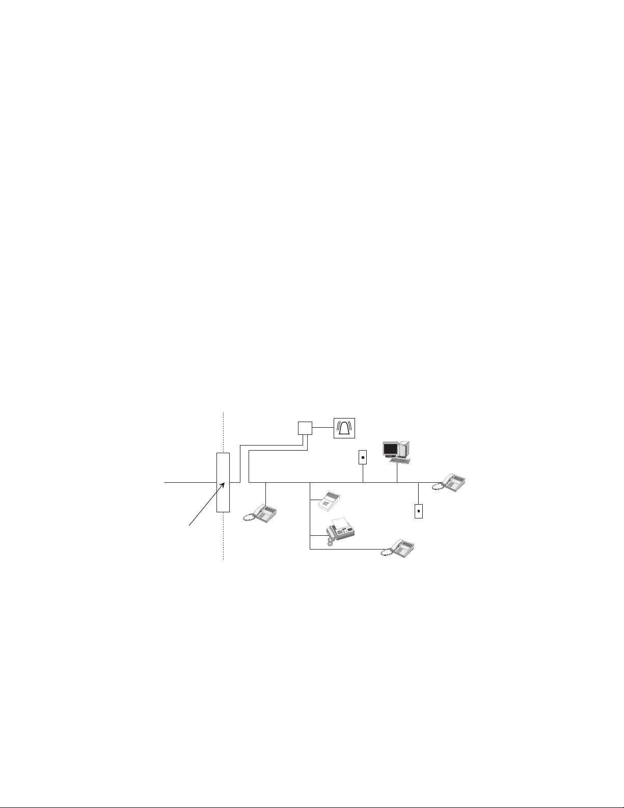
A plug and jack used to connect this equipment to the premises wiring and telephone network must comply with the applicable FCC Part 68 rules and requirements as adopted by ACTA. A compliant telephone cord and modular plug is provided with this product. It is designed to be connected to a compliant modular
jack that is also compliant. See the Installation Instructions for details.
Alarm dialing equipment must be able to seize the telephone line and place a call in an emergency situation. It must be able to do this even if other equipment
(telephone, answering system, computer modem, etc.) already has the telephone line in use. To do so, alarm dialing equipment must be connected to a properly
installed RJ31X jack that is electrically in series and ahead of all other equipment attached to the same telephone line. Proper installation is depicted in the following diagram. If you have any questions concerning these instructions, consult your local telephone company or a qualified installer about installing an RJ31X
jack and alarm dialing equipment for you.
C u s t o m e r P r e m i s e s E q u i p m e n t a n d W i r i n g
N e t w o r k
S e r v i c e
P r o v i d e r ' s
F a c i l i t i e s
R J 3 1 X
J a c k
R J - 1 1 J a c k
U n u s e d
A l a r m D i a l i n g
E q u i p m e n t
C o m p u t e r
T e l e p h o n e
L i n e
N e t w o r k
D e m a r c a t i o n
P o i n t
T e l e p h o n e
A n s w e r i n g
S y s t e m
F a x M a c
h i n e
T e l e p h o n e
T e l e p h o n e
U n u s e d
R J - 1 1 J a c k
If this equipment causes harm to the telephone network, the telephone company may temporarily disconnect your service. If possible, you will be notified in
advance. When advance notice is not practical, you will be notified as soon as possible. You will also be advised of your right
to file a complaint with the FCC.
The telephone company may make changes in its facilities, equipment, operations, or procedures that could affect the operation of the equipment. You will be
given advance notice in order to maintain uninterrupted service.
If you experience trouble with this equipment, please contact the company that installed the equipment for service and/or repair information. The telephone company may ask you to disconnect this equipment from the network until the problem has been corrected or you are sure that the equipment is not malfunctioning.
This equipment may not be used on coin service provided by the telephone company. Connection to party lines is subject to state tariffs.
Patent Information
This product and the use of this product may be covered by one or more of the following patents: 5,805,063, 5,872,512, 5,942,981, 5,686,896, 5,686,885,
4,855,713. Except expressly provided herein, the purchase of this product shall not constitute a license or otherwise provide a right to practice a method covered
by any of the identified patents. GE Security hereby grants the purchaser of this product a limited, non-exclusive license to practice the methods patented in the
identified patents solely with products manufactured, sold or licensed by GE Security. This license grant does not extend to the use of unlicensed, third party
products with this product.
Page 3
Commands at a Glance
D
Disarm the system.
Cancel an accidental alarm.
Arm to Level 2—STAY.* 2 + CODE
Arm to Level 3—AWAY.* 3 + CODE
Send a police alarm. Press and hold both POLICE buttons for
Send an auxiliary alarm. Press and hold both AUXILIARY
Send a fire alarm. Press and hold both FIRE buttons for 2
Arm system with No Delay.*
1 + CODE
CODE or 1 + CODE
2 seconds.
buttons for 2 seconds.
seconds.
8573G51A.
2 + CODE + 4 or
3 + CODE + 4
Arm system for Latchkey.* 2 + CODE + 6 or
3 + CODE + 6
Bypass a sensor.* Indirectly: 2 + CODE + # or
3 + CODE + #
Directly: # + CODE + Sensor Number
Arm system silently.*
5 + 2 + CODE or
5 + 3 + CODE
Arm system with exit lights
off.*
Turn all lights on/off. 0 + 0
Turn specific lights on/off. 0 + Light number
Check the system status. * for Short status or * + * for Full status
Turn Chime on/off. 7 + 1
Turn Energy Saver on/off. 7 + 2
Disable local phone access.**
(This is a phone command
only.)
Check alarm memory.
Activate Output.*** 7 + 7 + Output number (1–6)
View Event History
*If Quick Arm feature is on, access code is not required. See “Arming Your System”.
**Installer can disable local phone control if desired.
***Must be set up by installer.
2 + CODE + 0 or
3 + CODE + 0
# + 7 + 3
or wait 5 seconds after picking up the phone
7 + 6
8 + CODE + 8
Page 4

Concord 4 Series Security Systems0
Page 5

Contents
Commands at a Glance - 1
Getting to Know Your Security System 1
Communicating with the System 2
Instructing the System ...................................................................................................................2
Beeps and LEDs— How Your System Talks to You ....................................................................3
Notification by Pager ....................................................................................................................3
Panel ..........................................................................................................................................1
Touchpads .................................................................................................................................1
Door/Window Sensors ..............................................................................................................1
Motion Sensors .........................................................................................................................1
Environmental Sensors .............................................................................................................1
Optional System Components ...................................................................................................1
Alphanumeric and Fixed Display Touchpads ...........................................................................2
Wireless Handheld Touchpad ...................................................................................................2
Keychain Touchpads .................................................................................................................2
Touchtone Phones .....................................................................................................................2
Key Beeps .................................................................................................................................3
Status Beeps ..............................................................................................................................3
LEDs .........................................................................................................................................3
Basic System Operations 4
What Happens in an Alarm Condition ..........................................................................................4
Fire Alarms ....................................................................................................................................4
Automatic and Manual Fire Alarms .........................................................................................4
Clearing Alarms and Resetting Smoke Detectors .....................................................................5
Preventing Accidental Alarms ......................................................................................................5
Guidelines for Preventing Accidental Alarms ..........................................................................5
Aborting Accidental Alarms .....................................................................................................6
Arming and Disarming Your System ............................................................................................6
Level 1—OFF ...........................................................................................................................6
Level 2—STAY .........................................................................................................................7
Level 3—AWAY .......................................................................................................................7
Quick Arm ................................................................................................................................7
Quick Exit ..................................................................................................................................7
Keychain Touchpad Arming..................................................................................................... 8
Using the Chime Feature ...............................................................................................................8
Chime-On-Close .......................................................................................................................8
Using the Voice Chime Feature .....................................................................................................8
No Delay—For Instant Alarm....................................................................................................... 8
Auto STAY Arming Feature.......................................................................................................... 9
Exit Extension Arming Feature .....................................................................................................9
Arming Your System Silently .......................................................................................................9
Bypassing—Arming With a Door or Window Open .................................................................... 9
Bypassing a Sensor Directly .....................................................................................................9
Bypassing a Sensor Indirectly .................................................................................................10
Was the Bypass Successful? ...................................................................................................10
Basic Light Control .....................................................................................................................10
Basic Output Control ................................................................................................................... 11
v
Page 6

Checking the Status of Your System ........................................................................................... 11
Short System Status ................................................................................................................11
Full System Status ...................................................................................................................11
Panic Alarms 11
Fire Panic Alarm .........................................................................................................................12
Lighting During a Fire Panic Alarm .......................................................................................12
Police Panic Alarm ......................................................................................................................12
Lighting During a Police Panic Alarm ....................................................................................12
Auxiliary Panic Alarm ................................................................................................................12
Lighting During an Auxiliary Panic Alarm ............................................................................12
Siren Time-out .............................................................................................................................12
Access Codes 13
Programming Access Codes ........................................................................................................13
Access Code Integrity .............................................................................................................13
System Master Code Privileges ..............................................................................................13
Partition Master Code Privileges ............................................................................................13
Regular User Code Privileges .................................................................................................13
The Touchpad Tamper Feature ...............................................................................................13
Changing or Erasing User Codes ................................................................................................14
Changing a User Code ............................................................................................................14
Deleting a User Code ..............................................................................................................14
Assigning Code Attributes ..........................................................................................................14
Assigning the Direct Bypassing Attribute ..............................................................................14
Assigning the Remote Access Attribute .................................................................................14
Assigning the System Test Attribute .......................................................................................15
Assigning the Latchkey Report Attribute ...............................................................................15
Assigning the Partition Access Attribute (Concord 4 systems only) ......................................15
Setting the Time and Date 15
Adjusting System Sounds and Touchpad Brightness 16
Adjusting the Touchpad Beeps (Fixed Display Touchpad Only) ................................................16
Adjusting the System Status Voice Volume ................................................................................16
Adjusting the Touchpad Display Brightness ...............................................................................16
Using the Energy Saver Feature 17
Energy Saver Example ................................................................................................................17
Setting the Energy Saver High and Low Temperature Settings ..............................................17
Notification by Pager 18
Pager Messages .......................................................................................................................19
Event Code in Page..................................................................................................................19
Sensor Number or User Number in Page ................................................................................19
Account Number in Page ........................................................................................................20
Streamlining the Page Report ................................................................................................. 20
Creating Time Schedules 20
Scheduling Consecutive Days .................................................................................................20
One Day Rollover ...................................................................................................................20
Installation Instructionsvi
Page 7

Example 1 of One Day Rollover .......................................................................................................21
Example 2 of One Day Rollover .......................................................................................................21
Multiple Day Rollover ............................................................................................................21
Example of Multiple Day Rollover ...................................................................................................21
Attaching Time Schedules ...........................................................................................................21
Time Schedules and Partitions ....................................................................................................22
Advanced Light Control 22
Controlling Lights By Time Schedule .........................................................................................22
Controlling Lights with Sensors ..................................................................................................22
Installer Programmable Lighting ................................................................................................23
Controlling Outputs by Time Schedule 23
Scheduled Arming 23
Opening and Closing Reports 24
When Will this Feature Be Active? .............................................................................................24
Who Will Be Paged? ...................................................................................................................24
What Will the Pager Report? .......................................................................................................24
Latchkey Paging 24
Page In the Event of... .................................................................................................................24
Who Will Be Paged? ...................................................................................................................24
Who Can Send a Page? ...............................................................................................................24
What Will the Pager Report? .......................................................................................................25
Latchkey Opening .......................................................................................................................25
Basic Latchkey Opening .........................................................................................................25
Based on Time Schedule Only .......................................................................................................... 25
Based on Latchkey Modifier 6 Only .................................................................................................25
Advanced Latchkey Opening ..................................................................................................25
Latchkey Closing .........................................................................................................................25
Assigning a Time Schedule to Latchkey Paging .........................................................................25
Applying the Latchkey Modifier .................................................................................................26
Notify by Exception 26
Page In the Event of... .................................................................................................................26
Who Will Be Paged? ...................................................................................................................26
Who Can Send a Page? ...............................................................................................................27
What Will the Pager Report?....................................................................................................... 27
When Will this Feature Be Active?............................................................................................. 27
Assigning a Time Schedule to Exception Opening and Closing .................................................27
The No Activity Feature 27
Using the Panel Download Feature 27
Using a Partitioned System (Concord 4 systems only) 28
Global Settings ............................................................................................................................28
Partition-Specific Settings ...........................................................................................................28
Jumping Partitions .......................................................................................................................28
vii
Page 8

Arming and Disarming Another Partition ...............................................................................29
Programming Another Partition ..............................................................................................29
Arming and Disarming Multiple Partitions at the Same Time ....................................................29
Notes on Arming/Disarming Multiple Partitions from Alphanumeric
and Fixed Display Touchpads ............................................................................................................30
Notes on Arming/Disarming Multiple Partitions from Keychain Touchpads ...................................30
Macro Keys 30
System Information 31
Viewing the Event Buffer 31
Overview .....................................................................................................................................31
Using a Touchtone Phone to Operate Your System 34
Phone Command Prefix ..............................................................................................................34
Accessing the System from Off-site ............................................................................................34
How the Panel Answers the Phone .........................................................................................35
Ring-Hang-Ring Method ...................................................................................................................35
Twelve-Ring ......................................................................................................................................35
Codes with Remote Access Capability ...................................................................................35
Touchtone Phone System Operation ...........................................................................................35
Activating a Police Panic Alarm .................................................................................................36
Phone Questions? ........................................................................................................................37
What if someone calls while I’m operating the panel? ..................................................................... 37
Can I control the system while I’m talking on the phone? ................................................................37
How do I perform other phone operations without commanding my security system? ....................37
Testing the System 37
Automatic Test Features ..............................................................................................................37
Manual Tests ...............................................................................................................................37
Sensor Test ..............................................................................................................................37
Phone Communication Test ....................................................................................................38
Testing Sirens ..........................................................................................................................39
Troubleshooting 39
Trouble Beeps and Trouble Messages .........................................................................................39
Silencing Trouble Beeps .........................................................................................................39
Common Questions and Answers ...............................................................................................40
Phone Issues ............................................................................................................................40
Lighting Issues ........................................................................................................................40
Appendix A: User Sheets 42
System Sensors ............................................................................................................................42
User Codes ..................................................................................................................................43
Touchpad Information .................................................................................................................44
Alphanumeric and Fixed Display Touchpads .........................................................................44
Keychain Touchpads ...............................................................................................................44
Keychain Touchpad 1 ........................................................................................................................44
Keychain Touchpad 2 ........................................................................................................................45
Keychain Touchpad 3 ........................................................................................................................45
Keychain Touchpad 4 ........................................................................................................................45
Installation Instructionsviii
Page 9

Accidental Smoke and Fire Alarms ............................................................................................46
Dialer Abort .................................................................................................................................46
Doors and Delay Time Settings ...................................................................................................46
System Features............................................................................................................................46
If the Power Goes Out .................................................................................................................47
No Activity Time .........................................................................................................................47
Resetting the Smoke Detector .....................................................................................................47
System Information .....................................................................................................................47
Paging ..........................................................................................................................................48
Lights ...........................................................................................................................................48
Partition 1—House Code______.................................................. Partition 2—House Code______ 48
Partition 3—House Code______.................................................. Partition 4—House Code______ 48
Partition 5—House Code______.................................................. Partition 6—House Code______ 49
Outputs ........................................................................................................................................ 49
Energy Saver ................................................................................................................................49
Alarm Sounds and Status Beeps ..................................................................................................50
Appendix B: Planning for Emergencies 51
Floor Plan Example .....................................................................................................................51
Your Floor Plan ...........................................................................................................................52
Alarm System Limitations ..........................................................................................................54
If Your System Needs Service..................................................................................................... 54
Appendix C: Programming Your System 55
Two Methods to Program Your System ......................................................................................55
Using Programming Menus ........................................................................................................55
Examples of Programming Using Menus ...............................................................................55
Using Programming Shortcuts ....................................................................................................57
ix
Page 10

Installation Instructionsx
Page 11
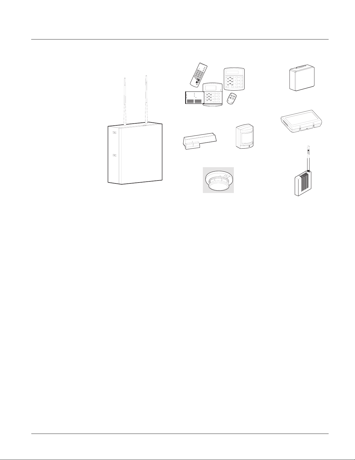
Getting to Know Your Security System
Your security system consists of different components. Each component plays a special role in
system operation (Figure 1).
St ay
Aw a y
Te st Sy st em W e e kly
O ff
3
A41
2
pre ss b ot h
Si le nt
Pa g er
N o D e la y
5 6
B
pre ss b ot h
Fe a tu re s
Sy s te m
M en u
8
C
7
9
pre ss b ot h
St at u s
Li gh ts
By p a ss
D
0 #
*
Energy Saver Module
Cellular Backup Module
Qu ic k Gu id e
Di sa rm S yst em / Ca nc el A lar m
Pre ss 1 + C O DE .
Ar m to ST A Y
1
2
3
Ar m to A W AY
1
2
3
Zo ne /S en so r Nu m be r
01
02
03
04
05
06
07
Clo se all pr ote cte d d oo rs an d w in dow s.
Pre ss 2 + C O DE .
Pre ss 4 t o a rm de lay do or s in st ant ly,
if d esi red .
Clo se all pr ote cte d d oo rs an d w in dow s.
Pre ss 3 + C O DE .
Ex it p rem is es thr ou gh de lay do or .
By pa ss Se ns or s
1
Arm s yst em to de sir ed lev el.
2
Pre ss BY PA SS + C OD E + Se nso r N o .
Tu rn C HI M E O n /O ff
1
Ma ke su re s ys tem is di sar me d.
2
Pre ss 7 + 1 to tu rn CH IM E on or of f.
Pro g ram Us er Se tt ing s
1
Ma ke su re s ys tem is di sar me d.
2
Pre ss A or B t o s cro ll t hro ug h me nu s.
Pre ss # t o s ele ct op tio n o r a cce pt en tr
Pre ss to d ese lec t o pti on or ca nc el e ntr y.
Pre ss 1 f or OF F; pr ess 2 for O N;
pre ss 0 - 9 f or oth er en tri es.
08
09
10
11
12
13
14
Te st Sys te m W ee kly
pre ss bo th
BA4
y.
pre ss bo th
C
pre ss bo th
D
Touchpads
Sy s te m i s O K
A rm e d
Re a d y
St ay
Aw a y
Of f
1
2 3
Si len t
Pa ge r
No De la y
5
6
Fe at ur es
Sy st em
M en u
7
8
9
St at us
Lig h ts
By p as s
0 #
*
Door/Window Sensors
Motion Sensors
Panel
Environmental Sensors
(Smoke Sensor shown)
Gateway Module
(System access via Internet)
Figure 1. Security System Components
Panel
The panel is the heart of your system. The panel circuitry is enclosed in a steel cabinet and is
installed out of the way of household or workplace traffic. The panel monitors all sensors and
devices in the system and initiates a call to the central monitoring station in an alarm situation.
Touchpads
Touchpads let you communicate with and control the system.You’ll use a touchpad to arm, disarm, and program your system.
Door/Window Sensors
Door and window sensors protect the perimeter of your home by detecting when a door or window is opened.
Motion Sensors
Motion detectors in hallways or individual rooms detect a person moving across the field of
detection.
Environmental Sensors
Environmental sensors such as smoke, heat, and carbon monoxide detectors remain alert for the
presence of fire or carbon monoxide 24 hours a day.
Optional System Components
Your system may include optional components that add the capability to:
• control heating/air-conditioning
• report alarms by cellular phone link in case landlines are down or inoperative
• control/monitor the system from on- or off-site using a touchtone phone or via the Internet
Concord 4 Series Security Systems 1
Page 12

Communicating with the System
Touchpads let you communicate with the system (Figure 2).
S y s te m i s O K
A rm e d
T e s t S y s t e m W e e k l y
A41
B
C
Q u i c k E x i t
D
A w a y
S ta y
O ff
2 3
p re ss b o t h
N o D e la y
S ile n t
5
p re ss b o t h
F e a t u r e s
p re ss b o t h
6
S ys te m
M e n u
8
7
9
S ta t u s
L i g h ts
B yp a s s
0 #
*
T e st S y s te m W ee k ly
A41
p re s s b o t h
B
p re s s b o t h
C
p re s s b o t h
D
R e a d y
A w ay
S t a y
O f f
2 3
P a g e r
N o D el a y
S il e n t
5 6
F e a t u r e s
S y s t e m
M en u
8
7
9
S t a t u s
L ig ht s
B y p as s
0
#
*
O F F
1
S T A Y
N O D E L A Y
2
A W A Y
4
3
C H IM E
5
7
6
S T A T U S
8
S T
9
B Y P A S S
0
B Y
C O M M A N D
Alphanumeric
Fixed Display
Wireless Handheld
Keychain
Figure 2. Touchpads
Alphanumeric and Fixed Display Touchpads
Alphanumeric touchpads are mounted on a wall and provide system information by LEDs and/or
displaying text messages.
Wireless Handheld Touchpad
This touchpad can be carried from room to room and used to control the system from many locations on site.
Keychain Touchpads
Keychain touchpads are handy for simple arming and disarming functions. They are wireless and
can be carried off-site in a purse or pocket. They can even be programmed to operate a gate,
garage door, or activate a Police or Auxiliary panic alarm.
Touchtone Phones
Your system can be set up for system operation from a touchtone phone on- or off-site. This
includes arming and disarming, plus system features such as checking the system status and turning on and off lights.
Instructing the System
Most of your instructions for the system consist of this basic pattern:
Command + Access Code
Not just anyone can walk up to a touchpad and operate your security system. Before the system
will process most commands, users are required to enter a 4-digit access code.
Keychain touchpads do not require an access code, but are usually kept in an individual’s pocket
or purse.
If you would rather use an actual key (Figure 3) to arm and disarm the system, your security
dealer can install a special key and keyswitch in your home.
Figure 3. Arm/Disarm Key
2
Concord 4 Series Security Systems
Page 13

Beeps and LEDs— How Your System Talks to You
Touchpads and interior sirens produce a variety of operating beeps to inform you of different system states and operations.
Key Beeps
A Key beep is the tone you hear when you press a button on an alphanumeric, fixed display, or
handheld wireless touchpad. The sound confirms that the button was pressed adequately. Key
Beeps can be turned on or off by the installer.
Status Beeps
Status beeps come from touchpads, sirens or speakers and are sounded when there is a change in
the current status of the system. Status beeps are not alarms, but they do warrant your attention.
There are different types of Status beeps:
• Exit Delay beeps indicate that an arming command has been entered and the countdown to
arming has begun.
• Entry Delay beeps indicate that you’ve entered the building and the countdown to an alarm
has begun. (So disarm the system as soon as you get in!)
• Protest beeps indicate that you’re trying to arm the system with an open door or window.
• Chime feature beeps indicate when a door or window is opened.
• Trouble beeps indicate a problem with the system or one of its components.
• Sensor test beeps occur during a sensor test to indicate that a sensor was tested properly.
Status beeps are described in more detail throughout the manual and in “Appendix A: User
Sheets”.
LEDs
Some touchpads have two LEDs that indicate the current system status at a glance. The red LED
is labeled Armed, the green LED is labeled Ready. The table below explains LED behavior.
System Status Red Armed LED Green Ready LED
Exit Delay Flashing
Armed to Level 1-Off Off On
Armed to Level 2—Stay or 3—Away On
Entry Delay Flashing Off
System Trouble (check system status)/Protest
System OK
Off
On
Notification by Pager
Your system can dial the phone numbers of five different pagers to notify pager holders of
important system events, including:
• System disarming
• System arming
• Trouble conditions
• Alarm conditions
For more information, see “Notification By Pager”.
Concord 4 Series Security Systems 3
Page 14

Basic System Operations
Note
Your system may or may not
be monitored. If it is not
monitored, no central station reports will be made.
This section describes:
• What Happens in an Alarm Condition
• Fire and Smoke Alarms
• Preventing Accidental Alarms
• Arming your System
• Exit and Entry Delay Times
• Bypassing Sensors
• Using the Chime Feature
• Basic Light Control
• Basic Output Control
• Checking the Status of Your System
For instructions on using a phone to perform any of these functions, see “Using a Touchtone
Phone to Operate Your System”.
What Happens in an Alarm Condition
• Speakers and touchpads emit emergency tones.
• System lights flash (requires optional equipment and programming).
• Panel notifies central monitoring station for help (monitored systems only).
• Pagers are notified of the event (requires optional programming).
Fire Alarms
Systems with smoke and/or heat detectors monitor for smoke and/or fire 24 hours a day in all
arming levels. During a fire alarm, system sirens sound a loud constant tone to alert you of a fire
alarm. Individual sensors also have built-in sounders to alert occupants.
You must respond quickly to fire alarms to ensure your safety and the safety of others.
To be prepared in case of a fire alarm:
• Plan escape routes. Two escape routes per room are recommended.
• Use a different escape route if closed doors feel warm or hot to the touch.
• Emphasize that everyone should escape as quickly as possible. DO NOT gather any belongings, which could delay you from getting out of the building safely.
• Crawl and hold your breath as much as possible to help reduce smoke inhalation during your
escape.
• Meet at a designated outdoor location.
• Emphasize that no one should re-enter the building if a fire exists.
• Notify the fire department from a safe location (if system is not monitored).
Automatic and Manual Fire Alarms
Automatic fire alarms occur when a smoke or heat sensor detects the threatening condition
(smoke/heat from a fire) and trips the panel, causing alarm sirens to sound. Manual fire alarms
are initiated by a person pressing the fire emergency panic buttons on a system touchpad or activating a manual pull fire device, causing alarm sirens to sound.
Note
While most alarms can be canceled or aborted to prevent reporting to the central monitoring station, fire
alarms CANNOT be aborted and are always reported. Since many communities charge for dispatching
the fire department in error, your dealer may give you specific instructions to follow in the event of an
accidental fire alarm. Record these instructions in Appendix A: User Sheets under “Accidental Smoke
and Fire Alarms”.
4
Concord 4 Series Security Systems
Page 15

If the system goes into a fire alarm automatically:
1. Immediately exit the building.
2. Notify the fire department from a safe location (if system is not monitored).
If you discover a fire emergency before the system goes into alarm automatically:
1. Press and hold both Fire button(s) for 2 seconds on the nearest touchpad or activate a manual fire pull.
2. Evacuate all occupants from the building.
3. Notify the fire department from a safe location (if system is not monitored).
Warning!
Do not re-enter the building if sirens stop. The sirens in your system are programmed to stop after a certain amount of time. This does not mean it is safe to reenter the building. Only fire department personnel can determine when it is safe to
re-enter.
Clearing Alarms and Resetting Smoke Detectors
Wireless smoke sensors reset themselves automatically, once they are clear of smoke. Some
hardwired smoke detectors must be manually reset once they are clear of smoke. Check with
your installer for reset procedures for your system.
To clear an alarm condition caused by wireless smoke sensors:
Press 1 + CODE. Touchpads display the sensor(s) that caused the alarm (alarm memory). If
sirens were still active, they will stop.
To clear an alarm condition caused by hardwired smoke sensors and reset the detec-
tors:
1. Press 1 + CODE. Touchpads display the zone(s) that caused the alarm (alarm memory). If sirens were still active, they will stop. The light on the smoke detector remains lit until it is reset.
2. Press 1 + CODE again to reset hardwired detectors and clear alarm memory.
Note
In some cases your installer may have installed a smoke detector reset switch. If so, use Step 2 only to
clear alarm memory. Press and hold the switch for at least one second, then release it to reset smoke
detectors.
The system may sometimes go into alarm again after clearing the alarm and resetting smoke
detectors. This usually indicates there is still smoke in the chamber inside the detector, even
though you may not see any smoke near it.You may need to clear this condition by fanning the
air near the detector for a few seconds, then use the appropriate procedure above again.
Preventing Accidental Alarms
Most accidental alarms occur when leaving the premises after arming the system, or upon returning, before disarming the system.
For example, if you arm the system then run upstairs for something you forgot, the Exit Delay
time may expire. Once the Exit Delay expires, opening an armed door or moving in front of a
motion detector will cause an alarm.
Guidelines for Preventing Accidental Alarms
The following guidelines will go a long way toward preventing accidental alarms.
• Close all doors and windows before leaving.
• Gather your belongings so you can exit immediately after arming the system.
• Always enter and exit within the programmed delay times.
• Make sure you leave through a designated delay door.
• Disarm your system immediately upon entry.
• Get familiar with all devices in your security system and learn how each one operates.
• If you have pets, ask your installer if you need pet lenses in your motion detectors.
Concord 4 Series Security Systems 5
Page 16

Note
Programmed Idle Text is
programmed by your
installer and typically identifies the property. For example, “ABC Bank” or “The
Jones’”.
• Check the location of smoke detectors. Smoke detectors located too close to bathrooms and
kitchens can trip from steam or smoke from cooking.
• Take note of system beeps, voice announcements, and indicator lights which indicate the
current system status.
Aborting Accidental Alarms
Your system can be set up to let you abort an accidental intrusion, Police or Auxiliary alarm.
If the Dialer Abort feature is turned on, disarming the system within a specified time period will
silence sirens and prevent the system from reporting to the central monitoring station (thus aborting the alarm). Your system will display “report aborted” for a few seconds, if you disarm before
the alarm is reported. If you don’t disarm in time to abort the central station report, the system
automatically sends an “alarm cancelled” report to the central station when the system is disarmed. Follow the procedures of your central station to prevent a false dispatch. See “Alarm
Information” in Appendix A to determine if this feature is enabled for your system.
The Dial Abort Delay feature is factory set to 30 seconds. Your installer can change this setting
from 15 - 45 seconds.
Note
Remember that fire alarms cannot be aborted/canceled. Disarming a fire alarm will only silence sirens,
but the alarm is still reported. If an accidental fire alarm has sounded, follow the procedures of your central monitoring station to prevent dispatching authorities.
To cancel a Police (intrusion) or Auxiliary alarm:
1. Press 1. Touchpads display “ENTER CODE.”
2. Enter your Access Code.
OR
Enter your Access Code
Touchpads display date and time or Programmed Idle Text. The system sounds one long beep.
If you’re using a Touchtone phone, see “Using a Touchtone Phone to Operate Your System”.
Arming and Disarming Your System
When arming the system you are turning on intrusion detection. When disarming the system you
are turning off intrusion detection.
Since your security needs may vary throughout the day, your system has three levels to meet
these different needs. By setting your system to a particular level, only those sensors programmed to detect in that level will activate an alarm.
Note
No matter which level your system is set to, sensors programmed as active 24 hours a day (smoke sensors, heat sensors, panic buttons, and environmental sensors) continue to monitor for and report alarm
conditions.
Note
Entry beeps are silenced
after the first keypress. They
will restart after five seconds
with no keypresses. You
must enter your access code
to completely disarm the
system.
6
Level 1—OFF
Select this level to:
• cancel an alarm and stop sirens.
• disarm the system when entering the armed premises (through a designated delay door).
Entry delay beeps sound to remind you the system is armed and that you must disarm it.
• disarm the system before opening a door or window while the system is armed (such as after
waking up in the morning and getting your newspaper).
To disarm to Level 1—OFF using a touchpad:
1. Press 1. Touchpads display “ENTER CODE.”
2. Enter your Access Code. Touchpads display date and time or programmed text and the sys-
tem sounds one long beep.
To disarm to Level 1—OFF using a keychain touchpad:
Press the Unlock button.
Concord 4 Series Security Systems
Page 17

Note
If Quick Arm feature is on,
an access code is not
required to arm the system
to Level 2— STAY.
Note
If Quick Arm feature is on,
an access code is not
required to arm the system
to Level 3— AWAY.
Level 2—STAY
Use this level to arm perimeter doors and windows only. Interior devices such as motion sensors
remain off so you can stay inside the premises without setting off an alarm. If you wish, you can
exit through a designated delay door after arming to Level 2—STAY.
To arm to Level 2—STAY using a touchpad:
1. Close all protected perimeter doors and windows.
2. Press
2 at any touchpad. Touchpads display, “ENTER CODE.”
3. Enter your Access Code. Touchpads display, “Armed to STAY” and the system sounds two short beeps.
4. If leaving the premises, exit through a designated delay door immediately.
To arm to Level 2—STAY using a keychain touchpad:
Press the Lock button once to go from Level 1 to Level 2.
Level 3—AWAY
Use this level to arm perimeter door/window sensors and interior motion sensors for maximum
protection.
To arm to Level 3—AWAY using a touchpad:
1. Close all perimeter doors and windows.
2. Press
3. Enter your Access Code. Touchpads display, “ARMED TO AWAY” and the system sounds
4. Exit through a designated delay door immediately.
• Press the Lock button twice to go from Level 1 to Level 3, or once to go from Level 2 to
3 at any touchpad. Touchpads display, “ENTER CODE.”
three short beeps.
To arm to Level 3—AWAY using a keychain touchpad:
Level 3.
Note
Contact your installer if you
want to use this feature.
Important !
If you step outside and are
planning to come back in, do
not close the door behind
you!
Quick Arm
This feature lets you arm your system without using an access code. Disarming the system still
requires entering an access code.
Quick Arm to Level 2:
From Level 1--Press 2.
Quick Arm to Level 3:
From Level 1 or 2--Press 3.
Quick Exit
Your system may be set up to let you exit and re-enter the premises within two minutes, without
disarming and rearming the system. This is useful when you want to quickly step outside to pick
up the newspaper without disarming your system.
To use Quick Exit:
1. When the system is armed to 2—STAY, Press D at any touchpad (opening the door without
pressing
2. Open a designated delay door and go outside. Leave the door open if you are planning to
come back in!
3. Return within two minutes and close the door. The system will rearm to 2—STAY.
D will cause an alarm).
Concord 4 Series Security Systems 7
Page 18

Keychain Touchpad Arming
Your installer can set up your keychain touchpad to arm the system in one of two ways:
• Press the Lock button to arm the system directly to Level 3—AWAY with no Exit Delay.
Using this method, you would not be able to arm to Level 2—STAY.
• Press the Lock button once for each desired increase in arming level. For example:
From Level 1 press the Lock button once to arm to Level 2, press it twice for Level 3, or
press it three times to arm to Level 3 with Latchkey activated (if programmed). The Exit
Delay time is applied. For more information, see “Latchkey Paging”.
Note
Your system can be set up to sound short beeps on exterior sirens when arming or disarming the system from outside using a keychain or wireless touchpad. This provides confirmation that an arming level
change was successful. Ask your installer about this feature.
Using the Chime Feature
Turning on the Chime feature is like having a doorbell on every protected door and window.
When this feature is on, interior sirens and speakers sound 2 beeps whenever anyone opens a protected door or window.
The Chime feature works only in Level 1—OFF.
To turn Chime on/off:
1. While in Level 1—OFF, from any touchpad, Press 7 + 1. While the Chime feature is on,
touchpads display, “CHIME IS ON” or “CHIME ON.”
Chime-On-Close
The Chime-On-Close feature works like the regular Chime feature, but in addition to the double
beeps heard upon opening a protected door or window, the system sounds one long beep when
the door or window is closed again.
You can turn the Chime-On-Close feature on or off from the programming menus. Refer to
“Using Programming Menus” for information on programming your system.
Note
If Quick Arm feature is on,
an access code is not
required. See the “Quick
Arm” section in this manual.
Using the Voice Chime Feature
Your system may have the ability to speak the sensor name whenever someone opens a protected
door or window. When this feature is on, speakers announce, “Sensor name open/closed.” You
can turn the Voice Chime feature on or off from the programming menus. Check with your
dealer and refer to “Using Programming Menus” for information.
No Delay—For Instant Alarm
You can choose to turn off the Entry and Exit Delays, causing the delay doors to arm immediately. Anyone entering through a delay door when the system is set to No Delay would immediately cause an alarm.
No Delay is normally used:
• When staying home after arming the system.
• When arming or disarming your system from outside (requires a wireless touchpad).
Arming to Level 2 or 3 with No Delay, using a touchpad:
1. Close all perimeter doors and windows.
2. Enter
3. Immediately press
Changing the arming level restores delay doors to their normal Exit and Entry Delay times.
2 + CODE or 3 + CODE. The system sounds two or three short beeps.
4. Touchpads display, “ARMED TO STAY NO DELAY” or “ARMED
TO AWAY NO DELAY”.
8
Concord 4 Series Security Systems
Page 19

Auto STAY Arming Feature
The Auto STAY Arming feature helps cut down on false alarms in the event that you arm the
system to 3—AWAY, but fail to leave during the Exit Delay time. Here’s how it works:
If you arm the system to Level 3—AWAY, and do not leave the premises within the Exit Delay time
With feature turned on The system detects that no one opened and closed a delay door
If feature turned off The system arms to Level 3—AWAY regardless of whether or not
within the delay time. It assumes that someone is still inside and
arms to 2—STAY to prevent a false alarm.
a delay door has been opened and closed.
Your movement inside the premises could activate a motion
detector, causing an alarm.
Exit Extension Arming Feature
The exit extension arming feature helps cut down on false alarms in the event that you arm the
system and exit the premises, but re-enter before the exit delay expires.
If you arm the system, leave the premises, and then re-enter within the exit delay time:
With feature turned on The system detects that a delay door opened twice within the delay
If feature turned off The exit delay continues to count down. Even if a delay door is
time. It assumes you re-entered the premises, so it restarts the exit
delay, giving you additional time to exit again.
opened a second time.
Your movement inside the premises could activate a motion
detector, causing an alarm.
Note
If Quick Arm feature is on,
an access code is not
required. See “Quick Arm”
for more information.
Note
Exit Delay is doubled when
arming silently.
Note
Smoke/heat sensors cannot
be bypassed.
Note
When a sensor is bypassed,
you are allowing that door or
window to be unprotected.
Note
You cannot bypass sensors
directly using a keychain
touchpad.
Note
If the exit extension arming feature is on, the exit delay will be restarted only once.
Arming Your System Silently
Use the Silent arming feature to arm your system without disturbing people throughout the house
with arming status beeps. Pressing
5—Silent before arming silences arming status and exit
beeps from touchpads and interior sirens, only for the current arming period.
To arm your system silently:
1. From any touchpad, press 5.
2. Within 4 seconds enter:
2 + CODE or 3 + CODE.
Bypassing—Arming With a Door or Window Open
It is possible to arm your system while leaving a door or window open. This is useful if, for
example, you like to sleep at night with a window open.
If the door or window has a sensor installed on it, the system must be told to ignore or bypass that
sensor when it’s open. All other sensors remain active.
There are two methods for bypassing a sensor:
• Directly — After arming the system, bypass door/window sensors before you open them.
You must know the sensor number of the door or window you wish to bypass. Your installer
can include the zone number as part of the sensor text.
• Indirectly — As you are arming, bypass sensors on doors and windows that are already
open. This method should not be used in UL Listed installations.
Bypassing a Sensor Directly
Use this method if the system is armed and you would like to open a window without disarming.
Refer to the “Appendix A: User Sheets” to determine the sensor number you wish to bypass.
To bypass sensors directly:
1. Close all doors and windows.
2. Arm your system to the desired level.
Concord 4 Series Security Systems 9
Page 20

3. At any touchpad, press # + CODE (# is labeled Bypass)
4. Touchpads display, “BYPASS SENSOR _ _,” or “ENTER SNSR _ _.” Enter the desired sensor number.
5. Touchpads display, “BYPASSED ZONES 01,” or “SENSOR 01 BYPASSED,” for example.
6. If the touchpad displays “INVALID,” or “FAILURE,” or if the touchpad sounds one long beep, make sure that you entered a valid sensor number. Smoke/heat sensors cannot be bypassed.
7. Bypass other sensors if desired, by repeating Step 3.
8. The bypassed doors or windows can now be opened.
To arm (unbypass) bypassed sensors:
1. Repeat the above procedure substituting the bypassed sensor number or,
2. Close bypassed doors and/or windows and arm your system again.
Bypassing a Sensor Indirectly
Use this method if you are arming the system and would like to bypass doors and windows
already open.
To bypass sensors indirectly:
1. Leave open only those doors and windows that are to remain open. Close all others.
2. Arm your system to the desired level. The touchpad emits protest beeps and displays “PROTEST,” because of the open sensor(s).
3. At any touchpad press
01,” or “SENSOR 01 BYPASSED,” for example.
4. The system sounds arming level beeps to indicate that the system is armed and open sensors have been successfully bypassed.
# (Bypass). Touchpads with displays show, “BYPASSED ZONES
Note
For system lights to respond
to basic and advanced light
commands, the light
switches must be turned on.
To arm (unbypass) bypassed sensors:
1. Close bypassed doors and/or windows.
2. Arm your system again.
To bypass sensors indirectly using a keychain touchpad:
1. Press the button once to arm the system and again to bypass open sensors.
Was the Bypass Successful?
To confirm whether or not a sensor was bypassed:
1. Press the Status button on the touchpad. (* is labeled Status.) Touchpads list bypassed sensors or zones.
Basic Light Control
There are two kinds of light control:
• Basic light control, offering instant light control at any touchpad, and
• Advanced light control, in which lights turn on and off automatically according to specific situations. (See “Advanced Light Control”).
To turn all lights on or off:
1. From any touchpad: Press 0 + 0.
From a 4-button keychain touchpad: Press the Lights button.
To turn a specific light on or off*:
1. From any touchpad: Press 0 + light number.
From a 4-button keychain touchpad:
You cannot turn on a specific light using a keychain touchpad.
10
Concord 4 Series Security Systems
Page 21

Refer to the User Sheets in Appendix A to determine which light number is associated with
which lamp.
Basic Output Control
Your system may be set up with programmed outputs that control special hardware installed in
your system. These outputs are usually set up to turn on automatically in response to certain
events.
Your installer may have configured your system so that you can control some outputs from your
touchpad. Have the installer list and explain any outputs that are programmed for your control.
Use the following procedure to turn an output on or off.
To turn the output on or off:
From any touchpad press 7 + 7 + output number. If the output was already activated, it will
shut off. If the output was off, it will activate.
Checking the Status of Your System
Checking the system status means finding out about the current condition of your system. This
includes finding out if any sensors are open or currently bypassed, whether or not the AC power
and backup battery are okay, the nature of the most recent alarm, and more, depending on the
features in use and the equipment in your system.
Check the system status if:
• Your system sounds trouble beeps (five short beeps every minute).
• Your touchpads display, “ALARM,” and “POLICE,” “AUXILIARY,” or “FIRE.”
• Your touchpads display, “PRESS STATUS” or a blinking ☛.
If an alarm or system trouble condition has occurred, it is displayed on a touchpad the first time
you perform a Short or Full Status check. Performing a system status check a second time displays the system status including any trouble conditions.
If any alarm or system trouble is active, it continues to show up in every status check until the
system is disarmed.
Short System Status
A Short Status indicates the current arming level, sensor status (whether open or bypassed), low
battery, supervisory, auxiliary phone, AC power or backup battery failures.
To get a Short System Status:
Press * (* is labeled Status.)
The system sounds beeps according to the current arming level (one for Level 1, two for Level 2,
three for Level 3). Touchpads display and optional voice modules announce the status information, for example, “SYSTEM IS OK,” or “SENSOR 02 OPEN.”
Full System Status
A Full Status combines the Short Status information with added details about specific system
features.
To get a Full System Status:
1. Press * + *. Interior sirens sound beeps according to the current arming level. Touchpads display and
optional voice modules announce the status information, for example, “SYSTEM IS OK,”
“SENSOR 03 BYPASSED,” “SYSTEM BATTERY IS OK,” “AC POWER IS OK.” If the
optional Energy Saver module or RF Thermostat is installed, the system displays/announces its
status (on/off) and the current temperature (if on).
Panic Alarms Panic alarms are easily activated from any touchpad to quickly alert the central monitoring sta-
tion to a Fire, Police, or Auxiliary emergency so the correct personnel can be dispatched immedi-
Concord 4 Series Security Systems 11
Page 22

ately. A panic alarm can be activated in any arming level. Each type of panic alarm sounds and
reacts differently when activated.
Type of Alarm Alarm Sound
Fire Repeating series of three beeps
Police Continuous tone
Auxiliary Rapid beeps
Fire Panic Alarm
The Fire panic alarm sounds from all interior and exterior sirens. On monitored systems, the central monitoring station responds by calling the fire department.
To activate a Fire panic alarm from a touchpad:
Press and hold both Fire button(s) for 2 seconds.
Lighting During a Fire Panic Alarm
If your system includes controlled lighting, all system lights turn on and remain on during a Fire
alarm.
Police Panic Alarm
The Police panic alarm sounds from all interior and exterior sirens, scaring off any intruder and
alerting neighbors. On monitored systems, the central monitoring station responds by calling the
police.
Note
Verify with your installer how
your keychain touchpads are
programmed. See “Appendix A: Keychain Touchpads”
for more information.
To activate a Police panic alarm from a touchpad:
Press and hold the Police button(s) for 2 seconds.
To activate a Police panic alarm from a keychain touchpad:
Press and hold the Lock and Unlock buttons together for 2 seconds.
Lighting During a Police Panic Alarm
If your system includes controlled lighting, all system lights flash continuously during a Police
panic alarm.
Auxiliary Panic Alarm
The Auxiliary panic alarm sounds from interior sirens only. It is typically set up by your security
dealer, based on your specific needs. On monitored systems, the central station responds by calling the service or agency you specified through your dealer, such as an ambulance service.
To activate an Auxiliary panic alarm from a touchpad:
Press and hold the Auxiliary button(s) for 2 seconds.
To send an Auxiliary panic alarm from a keychain touchpad:
Press and hold the Lights and Star buttons together for 2 seconds.
Lighting During an Auxiliary Panic Alarm
If your system includes controlled lighting, all system lights turn on and remain on during an
Auxiliary panic alarm.
12
Siren Time-out
If the system is not disarmed after an alarm, the sirens will continue to sound until the time-out
period is reached. The time-out period can only be programmed by your installer or dealer.
Concord 4 Series Security Systems
Page 23

Even though reaching the time-out stops the sirens, the alarm will still be in progress until the
system is manually disarmed.
Access Codes The system requires a valid access code before it will process most commands.
There is one System Master code which serves as the primary User Programming code for your
system. Only a very limited number of users will need to know this code.
Concord 4 systems have six Partition Master codes (one for each partition) which allow access
to system operations in their respective partitions. Concord Express V4 systems are single partition systems with no partition master codes.
Note
Partitions are individual security systems within the same control panel. Partitioned systems are typically used for large buildings with several entry/exit points and different access/operating hours. They
also work well for small strip malls, duplexes, and quad-homes where one control panel can provide
individual security for six different tenants.
Concord 4 systems have 230 Regular User codes (000-229), while Concord Express V4 systems
have 16 Regular User codes (00-15). These codes act like keys to arm and disarm the system. If
necessary, they can be assigned to neighbors, baby-sitters, or repair persons for temporary use.
Regular user codes can be changed in User Programming and are easily deleted from the system
when no longer necessary.
Programming Access Codes
The code you use to enter User Programming determines which features such as codes and code
attributes you’ll be able to change.
A user code can be given certain attributes that limit what the user can do within the system.
Attributes may be changed by you, or by a dealer over the phone using downloading software.
The User Sheets in Appendix A provide a location for you to record the actual user codes and the
attributes of each. If you need assistance in changing any code attributes contact your dealer.
Access Code Integrity
To preserve the integrity of your system, keep access codes confidential and delete extra codes as
soon as they are no longer needed.
Avoid using obvious code patterns such as
1234, 1111, 2222, etc.
System Master Code Privileges
Using the System Master code to enter User Programming lets you:
• Change the System Master code.
• Change or delete the Partition Master code in the current partition.
• Change or delete Regular User codes in the current partition.
The default System Master code is
the new code on the User Sheets in Appendix A.
1234. It is important that you change this default and record
Partition Master Code Privileges
Using the Partition Master code to enter User Programming lets you:
• Change the Partition Master code in the current partition.
• Change or delete Regular User codes in the current partition.
There are no default Partition Master codes. Record all codes on the User Sheets in Appendix A.
Regular User Code Privileges
You cannot enter User Programming with a Regular User code.
The Touchpad Tamper Feature
The installer can program your system to activate a Police alarm in the case of possible touchpad
tampering.
Concord 4 Series Security Systems 13
Page 24

Note
The system will not accept
the same code for two different users. To change System and Partition Master
codes please see Appendix
C: “Using Programming
Menus”.
If more than 40 keys are pressed when the system asks for a code, and those keystrokes are not
part of a valid access code, a siren will sound. Talk to your installer or see Appendix A “Touchpad Information” on page 44 to see if this feature is enabled.
Changing or Erasing User Codes
A Touchtone phone can be used to change or erase user codes, but alphanumeric or fixed display
touchpads work much better because of their extensive feedback. See Appendix C for phone programming instructions.
Changing a User Code
To change or assign a user code:
1. Enter the programming menus by pressing 9 + System or Partition Master CODE.
2. For Concord 4 systems, press
For Concord Express V4 systems, press
3. Enter the desired 4-digit code, then #.
4. Press
* + 00 + # to exit the programming menus.
Deleting a User Code
When a code is deleted, it can no longer operate the system.
To delete a user code:
1. Enter the programming menus by pressing 9 + System or Partition Master CODE.
2. For Concord 4 systems, press
For Concord Express V4 systems, press
3. Enter the System or Partition Master
4. Press
* + 00 + # to exit the programming menus.
030 nnn 0 where nnn is the user 000 through 229.
030 nn 0 where nn is the user 00 through 15.
030 nnn 0 where nnn is user 000 through 229.
030 nn 0 where nn is the user 00 through 15.
CODE, then #.
Assigning Code Attributes
Code attributes determine the limits or capabilities of a code. You will want certain users to have
more control over the system than others. For example, you would want an adult to have more
control over the system than a child. Below are code attributes that you can assign.
Assigning the Direct Bypassing Attribute
This attribute allows the user to bypass open sensors. If the user code does not have this attribute
turned on, the code restricts the user from bypassing sensors directly.
To assign Direct Bypassing to a user:
1. Enter the programming menus by pressing 9 + System or Partition Master CODE.
2. For Concord 4 systems, press
For Concord Express V4 systems, press
3. To turn Direct Bypassing:
on, press
off, press
4. Press
2 + #.
1 + #.
* + 00 + # to exit the programming menus.
Assigning the Remote Access Attribute
This attribute allows the user to access the security system from a telephone outside the protected
premises. If the user code does not have this attribute turned on, the code restricts user from
remote telephone access.
To assign Remote Access to a user:
1. Enter the programming menus by pressing 9 + System or Partition Master CODE.
030 nnn 1 where nnn is user 000 through 229.
030 nn 1 where nn is the user 00 through 15.
14
Concord 4 Series Security Systems
Page 25

2. For Concord 4 systems, press 030 nnn 2 where nnn is user 000 through 229.
For Concord Express V4 systems, press
3. To turn Remote Access:
on, press
off, press 1 + #.
4. Press
2 + #
* + 00 + # to exit the programming menus.
030 nn 2 where nn is the user 00 through 15.
Assigning the System Test Attribute
This attribute allows the user to perform system tests. If the user code does not have this attribute
turned on, the code restricts the user from performing phone or sensor tests.
To assign System Testing to a user:
1. Enter the programming menus by pressing 9 + System or Partition Master CODE.
2. For Concord 4 systems, press 030 nnn 3 where nnn is user 000 through 229.
For Concord Express V4 systems, press
3. To turn System Testing:
on, press
off, press
4. Press
2 + #.
1 + #.
* + 00 + # to exit the programming menus.
030 nn 3 where nn is the user 00 through 15.
Assigning the Latchkey Report Attribute
This attribute causes the panel to send a message to a pager when the user changes system arming
levels. See “Latchkey Paging”.
Setting the Time and Date
To assign Latchkey Report to a user:
1. Enter the programming menus by pressing 9 + System or Partition Master CODE.
2. For Concord 4 systems, press
For Concord Express V4 systems, press
3. To turn Latchkey Report:
on, press
off, press
4. Press
2 + #.
1 + #.
* + 00 + # to exit the programming menus.
030 nnn 4 where nnn is user 000 through 229.
030 nn 4 where nn is the user 00 through 15.
Assigning the Partition Access Attribute (Concord 4 systems only)
This attribute determines which partitions a regular user code can control. Only the System Master Code can be used to set this attribute.
To assign Latchkey Report to a user:
1. Enter the programming menus by pressing 9 + System Master CODE.
2. Press
3. Enter the desired partition numbers (1 - 6) you want this user code to control. The numbers
4. Press
Although the installer usually sets the time and date at the time of installation, the user can
change it when necessary.
1. Enter the programming menus by pressing 9 + System or Partition Master CODE.
2. Press
3. Enter the correct time in 24-hour format (4 digits--see Figure 4), then press
030 nnn 5 where nnn is user 000 through 229.
appear as you press the corresponding button. Remove undesired partition numbers by pressing the corresponding button. The numbers disappear from the display.
* + 00 + # to exit the programming menus.
To set the System Time:
020.
#. For example, if
the current time is 7:23 a.m., press
0723 + #.
Concord 4 Series Security Systems 15
Page 26

4. Press * + 00 + # to exit the programming menus.
p
p
2 4 - H o u r F o r m a t
Adjusting System Sounds and Touchpad Brightness
0 0 : 0 0
M i d n i g h t
0 1 : 0 0
1 : 0 0 a m
0 2 : 0 0
2 : 0 0 a m
0 3 : 0 0
3 : 0 0 a m
0 4 : 0 0
4 : 0 0 a m
0 5 : 0 0
5 : 0 0 a m
0 6 : 0 0
6 : 0 0 a m
0 7 : 0 0
7 : 0 0 a m
To set the System Date:
1. Enter the programming menus by pressing 9 + System or Partition Master CODE.
2. Press
3. Enter the current date as 6 digits (mm/dd/yy) then press
4. Press
021.
January 15, 2000, press
* + 00 + # to exit the programming menus.
011500 + #.
0 8 : 0 0
0 9 : 0 0
1 0 : 0 0
1 1 : 0 0
1 2 : 0 0
1 3 : 0 0
1 4 : 0 0
1 5 : 0 0
Figure 4. 24-Hour Format
8 : 0 0 a m
9 : 0 0 a m
1 0 : 0 0 a m
1 1 : 0 0 a m
N o o n
1 : 0 0 p m
2 : 0 0 p m
3 : 0 0
1 6 : 0 0
1 7 : 0 0
1 8 : 0 0
1 9 : 0 0
2 0 : 0 0
2 1 : 0 0
2 2 : 0 0
2 3 : 5 9
m
#. For example, if the current date is
4 : 0 0 p m
5 : 0 0 p m
6 : 0 0 p m
7 : 0 0 p m
8 : 0 0 p m
9 : 0 0 p m
1 0 : 0 0 p m
1 1 : 5 9
m
Adjusting the Touchpad Beeps (Fixed Display Touchpad Only)
The frequency or pitch of chime and trouble beeps from each fixed display touchpad can be
adjusted individually to a more desirable or distinct tone.
Chime and trouble beep tones sound using the default frequency during, or within 15 seconds of
any button activity at that specific touchpad.
To change status tone pitch:
1. Press and hold * + 0 until you hear a steady tone, then release the buttons.
2. Press and hold
3. Release the button when the desired pitch is heard. After about 15 seconds of no touchpad activity, the steady tone stops sounding.
1 to lower the pitch or press and hold 2 to raise the pitch.
Adjusting the System Status Voice Volume
If your system includes an optional voice module, you may want to adjust the volume at which
system status messages are announced.
To change the voice volume:
1. Enter the programming menus by pressing 9 + System or Partition Master CODE.
2. Press
3. Select a volume level
4. Press * + 00 + # to exit the programming menus.
043.
1 – 7 (7 being the loudest) and press #.
Adjusting the Touchpad Display Brightness
You may want to change the brightness of a touchpad display based on its location in a building
or room. For example, dim the touchpad display in a bedroom or enhance a display near a window.
Changing the touchpad display affects only the touchpad currently being used.
To change touchpad display brightness:
1. Enter the programming menus by pressing 9 + System or Partition Master CODE.
2. Press
043.
16
Concord 4 Series Security Systems
Page 27

3. Select a brightness level:
0 + # Off
1 + # Low
2 + # Medium
3 + # High
4. Press
After dimming the display, pressing any button momentarily returns the display to full bright-
ness. After 15 seconds without touchpad activity, the display returns to the set dimmed level. If
an alarm occurs while the display is dimmed, it automatically returns to the full brightness level
and stays that way until you disarm your system.
* + 00 + # to exit the programming menus.
Using the Energy Saver Feature
Use the optional Energy Saver feature to keep the premises within a user-designated temperature
range. High and low temperature points that you set override your normal heating and air conditioning temperature settings. Doing so allows you to use more energy-efficient settings when you
are away.
Energy Saver Example
• At your touchpad, you set a high temperature point (to trigger the air conditioner) and a low
temperature point (to trigger the furnace). This needs to be done only once, but can be
changed easily if necessary.
• Let’s say that you usually keep the temperature in your home at 68° F, but since no one will
be there during the day, you turn the Energy Saver feature on. If you’ve set the low temperature point to 55° F, the furnace will keep the house heated to 55° F.
• You’re about to return home and would like the house to be heated to its normal 68° F when
you arrive. If your system includes remote access, you can simply call home and turn the
Energy Saver feature off, giving control back to the furnace thermostat (68° F).
Control your air conditioning temperatures in the same manner.
In addition to controlling temperature, the Energy Saver feature notifies the central monitoring
station if your heating or air conditioning unit fails—before pipes freeze or pets are harmed by
extreme heat or cold.
Setting the Energy Saver High and Low Temperature Settings
Initially, you must set the energy saver to the desired high and low temperatures. This is done
only once, unless you want to change temperature settings.
The high and low settings you enter do not control heating and cooling systems, but determine
the point at which the furnace or air conditioner is activated (see Figure 5).
Concord 4 Series Security Systems 17
Page 28

Temperature settings can range from 45° to 90° Fahrenheit.
S
H i g h
S e t p o i n t
9 0 °
Note
Disarming the system turns
off the Energy Saver.
I f r o o m t e m p e r a t u r e
r e a c h e s h i g h
a i r c o n d i t i o n e r t u r n s o n .
I f r o o m t e m p e r a t u r e
r e a c h e s l o w s e t p o i n t ,
f u r n a c e t u r n s o n .
L o w
e t p o i n t
4 5 °
Figure 5.Energy Saver Setpoints
s e t p o i n t ,
To set the Energy Saver temperature range from a touchpad:
1. Enter the programming menus by pressing 9 + System or Partition Master CODE.
2. Press
070.
3. Enter the lowest temperature (45–89°F) you’ll allow before the furnace turns on, and press
4. Press
5. Press
B. Enter the highest temperature (46–90°F) you’ll allow before the air conditioner turns
on, then press
#.
* + 00 + # to exit the programming menus.
To override your normal heating or air conditioning settings, turn the Energy Saver feature on.
When you are ready to return to your normal temperature control settings, turn Energy Saver off.
To turn Energy Saver on/off from any touchpad:
1. Press 7 + 2. Alphanumeric touchpads display, “ENERGY SAVER IS ON,” for example.
#.
Notification by Pager
Your system can notify up to five different pager phone numbers to report system events. The
installer can program any numeric pager to receive pages for one or more of the following
groups.
High Level Reports Low Level Reports
Sensor Alarms Freeze Alarms Bypass Sensors AC Power Failure
Tamper Freeze Troubles Low Battery CPU Low Battery
Restorals No Activity Alarm Supervisory Auto Phone Test
Phone Tests Fire Panic Trouble CPU Back in Service
Receiver Failure Police Panic Phone Test Phone Failure
Receiver Jam Auxiliary Panic Event Buffer Full Touchpad Low Battery
Touchpad Tamper
Bus Failures
• Opening and Closing Reports
• Latchkey Reports
• Notify by Exception Reports
18
Concord 4 Series Security Systems
Page 29

Pager Messages
When an event is reported on a numeric pager, the following information is included:
Event Code
Sensor number or user number
Figure 6. Pager Messages
Last four digits of central
station account number
Although all three types of information can be reported on your pager, your pager service determines how the information will actually appear.
Event Code in Page
This number identifies what has happened.
Code Indicates
009 A sensor has been restored to its non-alarm state
111 System has been disarmed
115 Sensor test exit
118 System trouble has been fixed
119 System alarm condition has been cancelled
222 System armed to Level 2—STAY
333 System armed to Level 3—AWAY
555 System phone/sensor test
888 System has a trouble condition
999 System is in alarm condition
If a user arms the system to level 3 (AWAY) the pager will report that the system was armed to
level 3 (333). However, if the system is armed from a hardwired touchpad and the user does
not exit the premises, the arming level will revert to level 2 (STAY) without notifying the pager.
Sensor Number or User Number in Page
This number identifies who or what is causing the event.
Code Indicates
000 System event not caused by a sensor or user
001 — 096 Sensor numbers (1-96 for Concord 4, 1-32 for Concord Express V4)
600 — 829 User codes used (00-229 for Concord 4, 00-15 for Concord Express V4)
830 — 835 Partition master codes used (Concord 4 systems only)
846 System Master code used
847 Installer code used
848 Dealer code used
850 Quick Arm used
851 Keyswitch sensor used
852 System armed itself because it is being serviced or powered-up
Concord 4 Series Security Systems 19
Page 30

Account Number in Page
This number identifies where (which partition) the event is occurring.
Code Indicates
XXXX 4-digits of account number
Streamlining the Page Report
You can choose to have the four account number digits reported with every page, or to exclude
them. Each partition has its own account number, so seeing the digits is useful if multiple partitions are reporting to one pager.
Ask your dealer or installer if you would like the Streamline feature turned on.
Event Code
Sensor number or user number
Figure 7. Pager Message with Streamline Feature On
Creating Time Schedules
Time schedules are windows of time defined by a start time, a stop time, and the days of the week
these times are effective.
You can create up to 16 time schedules for setting up the following system features: light control,
output control, arming, Latchkey Paging, and Notify by Exception reports.
A Touchtone phone can be used to create time schedules, but alphanumeric or fixed display
touchpads work much better because of their extensive feedback. See Appendix C for phone programming instructions.
To define a time schedule:
1. At an alphanumeric or fixed display touchpad, enter programming menus by pressing 9 +
System or Partition Master
2. Press
3. Enter the start time in 24-hour format (00:00–23:59), then press
4. To display the current stop time for this schedule, press
5. Enter the stop time in 24-hour format, then press
6. Press
7. Enter
8. Press
9. When finished defining time schedules, press
05 nn 0 where nn is schedule 00 through 15.
The touchpad displays the new start time.
B until the touchpad displays a day of the week you wish to assign this schedule to.
2 + # to include the day in the schedule (“ON”).
1 +# to exclude the day in the schedule.
B to move to the next day of the week or press * and repeat steps 2–8 to define another
time schedule.
CODE.
#.
B once.
#. The touchpad displays the new stop time.
* + 00 + # to exit the programming menus.
20
Scheduling Consecutive Days
There may be instances when you’d like to schedule a feature event to start one day and stop the
next day or a number of days later.
One Day Rollover
You can create a schedule that begins on one day, and stops the next day by using only one time
schedule. (The stop time must be within 24 hours of the start time.)
Concord 4 Series Security Systems
Page 31

Example 1 of One Day Rollover
At home you’d like the Latchkey Opening feature to be effective from 10 p.m. on Tuesday until
5 a.m. on Wednesday (see Figure 8 Example 1).
By taking advantage of One Day Rollover, one time schedule can cover both days. (That schedule is illustrated in Figure 8.)
Notice how the stop time is within 24 hours of the start time. The system knows to apply the stop
time to the next day (5 a.m. on Wednesday).
Example 2 of One Day Rollover
Building on Example 1, let’s say that you’d like the Latchkey Opening feature to be effective
between 10 p.m. and 5 a.m., Monday through Friday (ending Saturday morning).
By simply applying the start and stop times to each day, one time schedule can cover the entire
week (see Figure 8 Example 2).
Multiple Day Rollover
The simplest method for defining a window of time that spans multiple days is to use 99:99 to
signify an open start or stop time.
Example of Multiple Day Rollover
At your business you’d like specific lights to remain lit from Friday afternoon through the weekend, until Monday morning.
In this situation, the lights need to be scheduled to roll over until they reach a recognizable stop
time.
In the Figure 8 Example 3, Schedule Y is set up to begin at 4 p.m. on Friday afternoon. Since the
stop time is 99:99, the lights will remain lit (roll over) until a recognizable stop time is reached.
Schedule Z is set up with an undefined start time (99:99), so if the lights were already lit, they
will remain lit until the Schedule Z stop time is reached at 5 a.m.
Example 1
S c h e d u l e
S t a r t
S t o p
M o n
T u e
W e d
T h u r
F r i
S a t
S u n
P a r t .
2 2 : 0 0
0 5 : 0 0
O F F
O N
O F F
O F F
O F F
O F F
O F F
Example 2
S c h e d u l e
S t a r t
S t o p
M o n
T u e
W e d
T h u r
F r i
S a t
S u n
P a r t .
X
2 2 : 0 0
0 5 : 0 0
O N
O N
O N
O N
O N
O F F
O F F
1
X
1
Figure 8. Time Schedule Rollover Examples
S t a r t
S t o p
M o n
T u e
W e d
T h u r
F r i
S a t
S u n
P a r t .
Example 3
S c h e d u l e
Y
1 6 : 0 0
9 9 : 9 9
O F F
O F F
O F F
O F F
O N
O F F
O F F
1 1
S c h e d u l e
Z
9 9 : 9 9
0 5 : 0 0
O N
O F F
O F F
O F F
O F F
O F F
O F F
Attaching Time Schedules
For any schedule to be effective, it needs to be attached to a feature. One schedule can be
attached to more than one feature event.
• See “Advanced Light Control” for information on attaching time schedules for light control.
• See “Controlling Outputs By Time Schedule” for information on attaching time schedules to
outputs.
• See “Schedule Arming” for information on attaching schedules to Arming.
Concord 4 Series Security Systems 21
Page 32

• See “Opening and Closing Reports” for information on creating opening and closing schedules.
• See “Latchkey Paging” for information on attaching time schedules to Latchkey Paging.
• See “Notify By Exception” for information on attaching time schedules to Notify by Exception.
Time Schedules and Partitions
Once a schedule is attached to a feature event in one partition, that schedule becomes unavailable
to the other partitions. This prevents the situation where one partition changes a time schedule
that inadvertently affects other partitions.
Advanced Light Control
You can control system lights from any touchpad, as discussed in “Basic Light Control”.
There are other lighting options that you or your installer can set up, including:
• Turning lights on and off according to a time schedule.
• Turning lights on after system arming for the duration of the Exit Delay.
• Turning lights on for the duration of the Entry Delay so you have enough light to see your
way to the touchpad to disarm the system.
• Flashing lights on and off upon successful arming and disarming.
Controlling Lights By Time Schedule
Lights can be turned on according to time schedules. If you need assistance setting up a time
schedule that fits your lighting needs, see “Creating Time Schedules”.
To schedule lights:
1. At an alphanumeric or fixed display touchpad, enter the programming menus by pressing
9 + System or Partition Master CODE.
2. Press
3. Press
4. Press
5. Enter
6. Press
7. When you’ve finished attaching the desired time schedules, press
0640 + #.
B until the touchpad displays the light number you would like to schedule. Refer to
“Appendix A: User Sheets” to determine which light number is associated with which lamp.
#. The touchpad displays the first available time schedule.
2 + # to assign the time schedule (“ON”) for this light.
1 + # to make the time schedule inactive for this light.
B to go to the next time schedule, if needed, and turn the schedule on or off for this
light.
* + 00 + # to exit the pro-
gramming menus.
Note
If a light is attached to a sensor and a schedule, the light
will only turn on and off
within the scheduled start
and stop times.
22
Controlling Lights with Sensors
Your security system can be programmed to turn on a selected light or lights when sensors are
activated. Each time the chosen sensor is activated, the attached light(s) will turn on for 5 minutes. When 5 minutes have passed since the last activation, the light(s) will turn off. For example,
if you want house lights to turn on when you open the front door, simply attach the desired lights
to the front door sensor.
To attach lights to sensors:
1. At an alphanumeric or fixed display touchpad, enter the programming menus by pressing 9 +
System or Partition Master
2. Press
080. The touchpad displays “LIGHT n TO Sn x” or “LT n SN x,” (where n is the light
number and x is the sensor number).
CODE.
Concord 4 Series Security Systems
Page 33

3. Press A or B until the light number (1–9) you would like to activate appears.
4. Enter the sensor number (1–96 for Concord 4, 1-32 for Concord Express V4) you wish to
activate the light and press
5. Press
1. At an alphanumeric or fixed display touchpad, enter the programming menus by pressing 9 +
2. Press
3. The touchpad displays “LIGHT n TO Sn x” or “LT n SN x,” (where n is the light number and
4. Press
5. Enter the sensor number as 0 (no sensor) and press #.
6. Press
B to assign another light to a sensor or press * + 00 + # to exit the programming
menus.
To detach lights from sensors:
System or Partition Master
B until the touchpad displays “ATTACH LIGHTS TO SENSORS” or “LITE TO SN”
then press
x is the sensor number).
#.
A or B until the light number (1–9) you would like to deactivate appears.
* + 00 + # to exit the programming menus.
#.
CODE.
Installer Programmable Lighting
If you would like specific lights to turn on during Entry and Exit Delay times, or if you would
like a light to flash to indicate successful arming and disarming, contact your installer.
Controlling Outputs by Time Schedule
Scheduled Arming
Note
Schedules cannot be used
to disarm the system.
Outputs may be used to control devices in your home such as automatic window blinds. Outputs
that your installer has enabled, can be turned on or off according to time schedules. If you need
assistance setting up a time schedule that fits your needs, see “Creating Time Schedules”.
To schedule outputs:
1. At an alphanumeric or fixed display touchpad, enter the programming menus by pressing 9 +
System or Partition Master
2. Press
3. The touchpad displays “OUTPUTS.” Press
4. Press
5. Press
6. Enter
7. Press
8. When you’ve finished attaching the desired time schedules, press
The Scheduled Arming feature allows the panel to be armed to Level 3—AWAY according to a
schedule. When an active schedule start time is reached the panel will exit User Programming,
automatically bypass any open sensors, and arm to Level 3—AWAY.
The panel will not arm according to an active schedule if the start time is reached while:
• The panel is already armed to Level 3—AWAY.
• The panel is performing a phone or sensor test.
To schedule arming:
1. At an alphanumeric or fixed display touchpad, enter the programming menus by pressing 9 +
2. Press
3. The touchpad displays “AWAY.”
065 + #
B until the touchpad displays the output number you would like to schedule. Refer to
“Appendix A: User Sheets” to determine which output is associated with which output number.
#. The touchpad displays the first available time schedule.
2 + # to assign the time schedule (“ON”) for this output.
1 + # to make the time schedule inactive for this output.
B to go to the next time schedule, if needed, and turn the schedule on or off for this out-
put.
gramming menus.
System or Partition Master
0660 + #.
CODE.
#.
* + 00 + # to exit the pro-
CODE.
Concord 4 Series Security Systems 23
Page 34

4. Press #. The touchpad displays the first available time schedule as “SCHEDULE 00 OFF,” or
“SCH 00 OFF.”
5. Enter
2 + # to assign the time schedule (“ON”) to arm the panel.
1 + # to make the time schedule inactive.
6. Press
7. When you’ve finished attaching the desired time schedules, press
B to go to the next time schedule, if needed, and turn the schedule on or off for arming
to AWAY.
* + 00 + # to exit the pro-
gramming menus.
Opening and Closing Reports
Latchkey Paging
The Opening and Closing Reports feature allows pager holders and/or the central station to be
notified whenever the system is armed and/or disarmed.
When Will this Feature Be Active?
The Opening and Closing Reports feature can be enabled only by the installer. There is nothing
more that the user needs to program in order to receive the Opening and/or Closing pages.
If a pager holder no longer wishes to receive the reports, the pager holder needs to contact the
installer to turn off this option for that pager.
Opening and Closing Reports occur without regard to any time schedule. There are no special
codes that the user needs to enter in order for the page to be sent.
Who Will Be Paged?
Your system can call up to 5 different pager numbers, as well as the central station, to report an
Opening and/or Closing Report.
Refer to “Appendix A: User Sheets” to see which pagers have been set up to receive a page for
this feature. Contact the installer if you would like to turn Opening and Closing Reports on or off
for any programmed pager or for the central station.
What Will the Pager Report?
For Opening Reports, the page reports the arming level as 111 (1—OFF) and the user.
For Closing Reports, the page reports the arming level as 222 (2—STAY) or 333 (3—AWAY),
and the user that armed to that level. See “Notification By Pager” for more information.
The Latchkey Paging feature allows programmed pager holders to be notified when the system is
armed and/or disarmed during specific hours or under certain conditions. For example, you could
program the Latchkey feature to page you if your child doesn’t arrive home and disarm the system (using a code with the Latchkey attribute) by the programmed Latchkey time.
24
Page In the Event of...
You can set up the Latchkey Paging feature to send a page in the following situations:
• Send a page when the system is disarmed. (Latchkey Opening)
• Send a page when the system is armed. (Latchkey Closing)
Who Will Be Paged?
Your system can call up to 5 different pager numbers to report a Latchkey Opening and/or a
Latchkey Closing. Latchkey pages do not report to the central station.
Refer to “Appendix A: User Sheets” to see which pagers have been set up to receive a page for
this feature. Contact the installer if you would like to turn Latchkey Paging on or off for any programmed pager.
Who Can Send a Page?
Only Latchkey-designated users can cause a Latchkey page to be sent. By default, this includes
the first six Regular User codes. If you would like to include a keychain touchpad as a latchkey
user, contact your installer. Any regular user code can be programmed with this attribute. See
“Assigning Code Attributes”.
Concord 4 Series Security Systems
Page 35

What Will the Pager Report?
For Latchkey Opening Reports, the page reports the arming level as 111 (1—OFF) and the user.
For Latchkey Closing Reports, the page reports the arming level as 222 (2—STAY) or 333 (3—
AWAY), and the user that armed to that level. See “Notification By Pager”.
Latchkey Opening
The installer can set up Latchkey Opening for one of two types of use: Basic and Advanced.
Basic Latchkey Opening
If your system is set up for Basic Latchkey, there are two ways to send a Latchkey Opening page:
Based on Time Schedule Only
1. Assign the Latchkey Opening feature a time schedule. (This needs to be done only once.)
2. Arm the system.
3. Disarming of the system by a Latchkey-designated user within the assigned time schedule, sends an Opening page.
Based on Latchkey Modifier 6 Only
1. Arm the system, then press 6, or press the Lock button on a keychain touchpad after arming
to 3—AWAY.
2. Disarming of the system by a Latchkey-designated user sends an Opening page, regardless of assigned time schedule:
Advanced Latchkey Opening
If your system is set up for Advanced Latchkey use, there is one way to send a Latchkey Opening
page:
1. Assign the Latchkey Opening feature a time schedule. (This needs to be done only once.)
2. Arm the system, then press
to 3—AWAY.
3. Disarming of the system by a Latchkey-designated user within the assigned time schedule, sends an Opening page:
In Advanced Latchkey use, paging is available only during the time schedule(s) that you assign
to it.
6, or press the Lock button on a keychain touchpad after arming
Latchkey Closing
Latchkey Closing can be used alone, or in addition to Latchkey Opening.
1. Assign the Latchkey Closing feature a time schedule.
2. The system is disarmed.
3. Arming of the system by a Latchkey-designated user within the assigned time, schedule sends a Closing page:
A Touchtone phone can be used to set up Latchkey paging, but touchpads work much better
because of their extensive feedback. See “Appendix C” for touchpad and phone programming
instructions.
Assigning a Time Schedule to Latchkey Paging
Follow these steps to attach a time schedule to Latchkey Opening and/or Latchkey Closing. If
you need assistance setting up a time schedule that fits your needs, see “Creating Time Schedules”.
Scheduling Latchkey Opening and/or Closing:
1. At an alphanumeric or fixed display touchpad, enter the programming menus by pressing
9 + System or Partition Master CODE.
2. Press
Concord 4 Series Security Systems 25
0600 + #.
Page 36

Note
6 must be pressed within 5
seconds of arming. If Quick
Arm feature is on, an access
code is not required. See
“Quick Arm” for more information.
3. To schedule: Latchkey Opening, press
“LATCH OPEN.”
Or, press
then press
If you want a page to be sent every time Latchkey-designated user codes arm or disarm the
system, apply the same time schedules under Latchkey Opening and Latchkey Closing.
4. The touchpad displays the first available time schedule.
5. Enter
2 + # to assign the time schedule to the event.
1 + # to make the time schedule inactive for the event.
6. Press
7. Press
8. When you’ve finished attaching the desired time schedules, press * + 00 + # to exit the pro-
gramming menus.
B until the touchpad displays “LATCHKEY CLOSING” or “LATCH CLOSE,”
#.
# to secure your choice.
B to go to the next schedule and repeat step 5.
# when the touchpad displays “LATCHKEY OPENING” or
Applying the Latchkey Modifier
The Latchkey modifier (6) is pressed after the arming keypress sequence.
Applying the Latchkey modifier from a touchpad:
1. At any touchpad, press 2 3 + CODE + 6.
The touchpad displays, “LATCHKEY PAGER ON” or “PAGER ON.”
To apply the Latchkey modifier using a keychain touchpad:
Press the Lock button when the system is armed to level 3—AWAY.
Notify by Exception
The Notify by Exception feature allows programmed pager holders and/or the central station to
be notified when arming or disarming occurs outside of specified time schedules.
Here are two specific examples of how the Notify by Exception feature might be used in a business setting:
• Every morning you’d like to be notified if your business is disarmed after its normal opening
time.
• Every evening you’d like to be notified if your business is armed before its normal closing
time.
Page In the Event of...
You can set up the Notify by Exception feature to page in the following instances:
• Send a page if the system is disarmed before the Opening time schedule begins or after the
Opening time schedule has ended. (Exception Opening)
• Send a page if the system is armed before the Closing time schedule begins or after the Closing time schedule has ended. (Exception Closing)
Who Will Be Paged?
Your system can call up to 5 different pager numbers to report an Open Exception and/or Closed
Exception. You can request that the central station receive these two reports as well.
Refer to “Appendix A: User Sheets” to see which pagers have been set up to receive a page for
this feature. Contact the installer if you would like to turn the Notify by Exception feature on or
off for any programmed pager or the central station.
26
Concord 4 Series Security Systems
Page 37

Who Can Send a Page?
All user codes and keychain touchpads will send a page if used while Notify by Exception feature is in effect.
What Will the Pager Report?
Exception Opening Reports report the arming level as 111 (1—OFF) and the user that disarmed
the system.
Exception Closing Reports report the arming level as 222 (2—STAY) or 333 (3—AWAY), and
the user that armed to that level. See “Notification By Pager”.
When Will this Feature Be Active?
The most typical setup of this feature makes use of both Exception Opening and Exception Closing. (It is possible to use only Exception Opening or only Exception Closing, however.)
Assigning a Time Schedule to Exception Opening and Closing
Follow these steps to define Opening and Closing schedules for Exception paging. If you need
assistance setting up a time schedule that fits your needs, see “Creating Time Schedules”.
A Touchtone phone can be used to set up Notify by Exception, but touchpads work much better
because of their extensive feedback. See “Appendix C” for programming instructions.
Scheduling Exception Opening and/or Closing:
1. At an alphanumeric or fixed display touchpad, enter the programming menus by pressing 9 +
System or Partition Master
2. Press
3. To schedule:
Exception Opening, press
Exception Closing, press
4. The touchpad displays the first available time schedule.
5. Enter
6. Press
7. Press
8. When you’ve finished attaching the desired time schedules, press
0620 + #.
“ECEPT OPEN,” then press #.
“ECEPT CLOSE,” then press
2 to assign the time schedule to the event.
1 to make the time schedule inactive for the event.
# to secure your choice.
B to go to the next schedule and repeat step 5.
gramming menus.
CODE.
# when the touchpad displays “EXCEPTION OPENING” or
B until the touchpad displays “EXCEPTION CLOSING” or
#.
* + 00 + # to exit the pro-
The No Activity Feature
Using the Panel Download Feature
Concord 4 Series Security Systems 27
The system can monitor the activity in your home and automatically call for help if normal activities are not detected within a defined period of time. For example, if someone falls and can’t
move, the system detects that normal activities such as placing outgoing calls or opening doors
and windows, have not occurred for a predetermined amount of time.
The system sounds a low-volume auxiliary alarm to let you know there may be a problem. If all
is well, you can stop the siren by disarming your system. If no one disarms the system for 5 minutes, your system calls the central monitoring station. The central monitoring station will respond
in accordance to the guidelines set forth in your monitoring agreement.
Refer to “Appendix A: User Sheets” to see if the No Activity feature is currently available to you
and the duration of the No Activity setting. If the feature is not currently available to you and you
wish to have it, contact your dealer.
Downloading is performed only by your dealer using software specifically designed for this system. It allows the dealer to change programming without sending a service person to the site.
Turning the Download feature on gives the dealer remote access to your system in order to:
• Update your account.
Page 38

Note
Before allowing any download sessions, the system
must be disarmed to level
1—OFF.
• Back up data from your system.
• Allow your dealer to quickly implement requested programming changes.
To enable/disable the Panel Download setting:
1. Enter the programming menus by pressing 9 + System or Partition Master CODE.
2. Press
3. To turn Downloading:
on, press
off, press
4. Press
041.
2 + #. The dealer will be able to access your system remotely if necessary.
1 + #. The dealer will not be able to access your system remotely.
* + 00 + # to exit the programming menus.
Using a
Partitioned
System
systems only)
(Concord 4
Concord 4 systems can be set up by your installer to operate as a multiple-partitioned system.
Partitioned systems provide security for up to six individual customers or areas of a building
from a single control panel. Partitioned systems are useful in strip malls or multi-family housing.
Global Settings
Global system settings affect all partitions. Most are set by the installer. Global settings that are
programmed by the user include:
• Time and Date
• System Master code
Partition-Specific Settings
Partition-specific settings affect only one partition. User-programmable, partition-specific settings include:
• 6 Partition Master codes (1 per partition)
• 230 Regular User codes (total for all partitions combined)
• 16 time schedules (total for all partitions combined)
• 9 Advanced Light Control set-ups available to each partition
• Latchkey feature
• Notify by Exception feature
• Scheduled Arming feature
• Speaker volume settings
• Energy Saver feature and its high and low setpoints.
To program any of these features for another partition, you must enter the User Programming
menu from a touchpad in that partition, or jump into that partition, then enter the User Programming menu.
Note
If your system uses just one
partition, skip this section.
28
Jumping Partitions
Typically, you would operate Partition 1 from a touchpad within Partition 1. However, if you
have access to Partition 3 and want to avoid walking a long distance to a Partition 3 touchpad,
you can access Partition 3 from the Partition 1 touchpad by jumping partitions. Depending on
how your installer programmed your system, you may or may not have to enter an access code to
jump partitions.
The ability to jump to another partition is an attribute you assign to each user code (see “Assigning Code Attributes”). Each code has unique partition number assignments that it can control. By
default, the System Master is the only code that can jump partitions. Refer to the “Appendix A:
User Sheets” to see if any other access codes have the ability to jump partitions.
Concord 4 Series Security Systems
Page 39

To jump partitions using an access code:
1. From any hardwired touchpad, press 8 + CODE + 6.
Touchpads display, “ENTER PARTITION” or “ENTER CMD.”
2. Press
the desired partition number (1 - 6).
The touchpad sounds one short beep if the jump was successful. One long beep means the
jump was not successful. Alphanumeric touchpads display the text in the newly entered partition.
3. Proceed to arm, disarm, or program as needed. The partition assignment reverts back if no touchpad buttons are pressed for 10 seconds.
To jump partitions without using an access code:
1. From any hardwired touchpad, press 7 + 4. Touchpads display, “ENTER PARTITION” or “ENTER CMD.”
2. Press
the desired partition number (1 - 6).
The touchpad sounds one short beep if the jump was successful. One long beep means the
jump was not successful. Alphanumeric touchpads display the text in the newly entered partition.
3. Proceed to arm, disarm, or program as needed. The partition assignment reverts back if no touchpad buttons are pressed for 10 seconds.
Arming and Disarming Another Partition
Any access code that can jump to another partition can control that partition. Once in the other
partition, you must use a valid code for arming and disarming that partition.
Programming Another Partition
Only System Master and Partition Master codes can be used for programming. Only one partition
can be programmed at a time. When one partition is in the programming mode, touchpads in the
other partition are locked out from any programming activity. However, arming and disarming
can continue.
Some partition-specific settings share resources, such as access codes and time schedules. For
example, if Partition 1 uses Regular User numbers 00 through 20, Partition 2 will not be able to
see or use those user numbers. The first Regular User number available for Partition 2 would be
21.
The allocation of time schedules works in much the same manner. There are 16 schedules that
can be used by any partition, but as soon as Partition 1 attaches a schedule to any event, that
schedule cannot be used by another partition, and vice versa.
Arming and Disarming Multiple Partitions at the Same Time
Note
Check with your installer to
identify which keychain
touchpads can arm/disarm
multiple partitions.
Concord 4 Series Security Systems 29
Your system may be set up to let you simultaneously arm and disarm more than one partition.
This can be done from system touchpads or keychain touchpads assigned to the associated partitions.
To arm multiple partitions at the same time from a touchpad:
1. Press 2 or 3 on any touchpad assigned to one of the partitions you want to arm. The display shows “ENTER CODE”.
2. Enter your Access Code. The display shows all the partitions that will be armed.
3. Press # to arm all displayed partitions.
Or,
Press the number of any partitions you don’t want armed (the partition numbers disappear
from the display), then press #.
To disarm multiple partitions at the same time from a touchpad:
1. Press 1 on any touchpad assigned to the partitions you want to arm. The display shows “ENTER CODE”.
2. Enter your Access Code. The display shows all the partitions that will be disarmed.
Page 40

3. Press # to disarm all displayed partitions.
Or,
Press the number of any partitions you don’t want disarmed (the partition numbers disappear
from the display), then press #.
4. If desired, press 4 (No Delay) or 6 (Latchkey) to activate those features.
Notes on Arming/Disarming Multiple Partitions from Alphanumeric and Fixed Display Touchpads
• A partition cannot be armed or disarmed if it is being controlled by another source at that
time. For example, if you are at a Partition 1 touchpad and are attempting to arm Partitions 1
and 2, a Partition 2 touchpad in use at that same time prevents arming of that partition.
• Any arming modifiers (4—No Delay, 6—Latchkey) selected at arming apply to all associated
partitions. However, silent arming (5—Silent) only affects the partition you are arming from.
All other partitions sound exit beeps to notify occupants that those partitions are arming.
• When arming multiple partitions, any conditions that prevent arming (open, trouble, active
alarm, etc.) are identified on system touchpad displays with the affected partition number
flashing. (If arming from a keychain touchpad, the condition is displayed on touchpad displays in the affected partition, while other touchpad displays show PROTEST). The normal
protest/auto force arm sequence follows, or you can press * to cancel the arming request.
• When disarming multiple partitions, any partitions in alarm have the affected partition number flashing on system touchpad displays. Pressing
# cancels all alarms in the associated par-
titions. Alarm memory information is then displayed for all canceled alarms.
To arm multiple partitions at the same time from a keychain touchpad:
Press the Lock button.
To disarm multiple partitions at the same time from a keychain touchpad:
Press the Unlock button.
Notes on Arming/Disarming Multiple Partitions from Keychain Touchpads
• A partition cannot be armed or disarmed if it is being controlled by another source at that
time. For example, if you press the Lock button attempting to arm Partitions 1 and 2, a
Partition 2 touchpad in use at that same time prevents arming.
• When arming multiple partitions, any conditions that prevent arming (open, trouble, active
alarm, etc.) are identified on system touchpad displays in the affected partition, while other
touchpad displays show PROTEST. The normal protest/auto force arm sequence follows, or
you can press * on a system touchpad to cancel the arming request. Pressing the Lock
button again during the protest condition bypasses any open sensors in the associated partitions and arms those partitions.
• When disarming multiple partitions and alarms are active in one or more of the associated
partitions:
a). Protest beeps sound for five minutes in all partitions being disarmed;
b). Partitions in alarm where sirens have timed out sound protest beeps for five minutes;
c). Partitions in alarm with active sirens continue sounding the alarm.
Warning!
Anytime alarms are active, the premises may not be safe to enter. Proceed as follows:
1.) Leave and call for help from a safe location and wait for authorities to arrive.
2.) When it is determined safe to enter the premises, go to a system touchpad and check
the system status to determine the alarm source. Disarm and alarm memory is displayed
for all associated partitions.
3). Press the Unlock button a second time (within the five minute protest period) to dis-
arm all associated partitions and cancel all alarms, then go to a system touchpad and
check alarm memory to determine the alarm source.
Macro Keys Your system may include touchpads with macro keys that allow one-touch operation. These are
four buttons located at the bottom of the touchpad. From the factory these buttons are labeled and
work as follows:
• CHIME—press once to turn chime on, press again to turn chime off.
• STAY—press once to arm to Level 2—STAY.
30
Concord 4 Series Security Systems
Page 41

Note
Macro Keys should not be
programmed to disarm the
system.
• EXIT— press once to use the Quick Exit feature.
• AWAY—press once to arm to Level 3—AWAY.
Your installer can also program these buttons to perform a system command different from those
described. For example, instead of entering the command 2 + CODE + 4 + 6 (arm to STAY with
No Delay and Latchkey), your installer can program one of the macro keys to perform the task
with just one press. Check with your installer for more information.
System Information
Viewing the Event Buffer
Note
Fixed Display Touchpads
cannot be used to view the
event history.
There is information about your system that is useful to know. This includes the factory code, the
system number, the system level, and software version.
After identifying the information for your system, make a note of it in the “Appendix A: User
Sheets”.
To identify system information:
1. Enter the programming menus by pressing 9 + System or Partition Master CODE.
2. Press
The first information displayed is the factory code. For example, “F nnn – nnnn,” or “FAC-
Press
Press
Press
3. Press
You have the option to view the event history for each partition of your system. These events
include arming, disarming, tampers, programming entries, just to name a few.
010.
TORY CODE nnn * nnnn.”
B to display the system number. For example, “N – nnnnnnn,” or “SYSTEM NUM-
BER nnnnnnn.”
B to display the system level. For example, “L nnnn,” or “SYSTEM LEVEL nnnn.”
B to display the software version. For example, “P nnnn,” or “SW VERSION nnnnx.”
* + 00 + # to exit the programming menus.
Overview
• The System Master Code can view all events from any partition. The partition masters can
only view global system events and events related to their respective partition. Regular user
codes cannot view event history.
• All partitions can view event history simultaneously, but only one touchpad at a time can
view the history in each partition. While the event history is being viewed, all other controlling sources are disabled (except for panic alarm buttons) and non-viewing touchpads display
“VIEWING EVENT BUFFER”.
To view event history:
1. The current partition must be armed to level 1 or 2.
2. At an alphanumeric touchpad, press 8 + System or Partition Master CODE + 8.
• The touchpad displays “VIEWING EVENT BUFFER” followed by the event description,
date/time or details (user, source, zone, etc).
• The most recent event appears first.
• Scroll through the events by pressing the A (back) and B (forward) keys.
• The C key is used to toggle the second line display between Date/Time and Details.
• Press the * key to exit Viewing Event History.
Concord 4 Series Security Systems 31
Page 42

• The Viewing Event History mode will exit automatically after one minute of inactivity OR
when an alarm occurs.
The following table is a comprehensive list of displayed events and their associated details (partition, current arming level, zone, bus unit number, source and user). If details are displayed for an
event an X will appear in the table.
• Partitions are displayed as P1 - P6, depending on which partition the event occurred.
• Current Arming Level will display Lx, where x is the current arming level of the event.
• Zone will display Zx, where x is the zone of the event.
• Bus Unit Number will display Bx, where x is the unit number of the Bus device.
• Source will display Sxxx, where xxx is the source number in the event (see table on source
numbers for more information).
• User will display Uxxx, where xxx is user number in the event (see table on user numbers for
more information).
Current
Event Display Partition
AC Power Failure AC POWER FAILURE X
AC Power Restoral AC POWER RESTORAL X
Antenna Tamper RCVR TAMPER X X
Arming Level Change
Auto Force Arm AUTO FORCE ARM X X X
Auto Phone Test AUTO PHONE TEST X
Auxiliary Panic AUXILIARY PANIC X X
Auxiliary Panic Cancelled AUXLRY CANCELLED X X
Bus Cover Tamper BUS TAMPER X X
Bus Failure BUS FAILURE X X
Closing Report CLOSING REPORT X X X X
CPU Back In Service BACK IN SERVICE X X
CPU Battery Restoral BATTERY RESTORED X
CPU Low Battery CPU LOW BATTERY X
Daylight Savings Time Adjust DAYLIGHT SAVINGS
Download Session Entry DOWNLOAD ENTRY
Download Session Exit DOWNLOAD EXIT
Duress Alarm DURESS X X
Event Buffer Viewing Entry EVENT VIEW ENTRY X X X
Event Buffer Viewing Exit EVENT VIEW EXIT X X X
Fire Panic FIRE PANIC X X
Fire Panic Cancelled FIRE CANCELLED X X
Force Arm FORCE ARM X X X
Installer Programming Entry INST PROG ENTRY X X X
Installer Programming Exit INST PROG EXIT X X X
Lost Event (buffer overflow) LOST EVENT
Main Unit Tamper MAIN UNIT TAMPER X
Memory Clear MEMORY CLEAR
Memory Failure MEMORY FAILURE
No Activity Alarm ACTIVITY ALARM X
3
ARM LEVEL CHANGE X X X
Arming
Level
Zone
Bus Unit
Number
Source 1User
2
32
Concord 4 Series Security Systems
Page 43

Event Display Partition
Current
Arming
Level
Zone
Bus Unit
Number
Source 1User
No Activity Cancelled ACTIVITY CANCEL X X
Opening Report OPENING REPORT X X X X
Phone Failure PHONE FAILURE X
Phone Line Test Failure PHONE LINE FAIL X
Phone Line Test Restoral PH LINE RESTORED X
Phone Test PHONE TEST X X X
Police Panic POLICE PANIC X X
Police Panic Cancelled CANCELLED X X
Receiver Failure RECEIVER FAILURE X X
Receiver Jam RECEIVER JAM X X
Recent Closing RECENT CLOSING X X X
Remote Access Lockout REMOTE LOCKOUT
Repeater Jam REPEATER JAM X X
Repeater Jam Restoral JAM RESTORED X X
Siren Trouble SIREN TROUBLE
Swinger Shutdown SWINGER X X
Time Change TIME CHANGE
Touchpad Tamper TOUCHPAD TAMPER X X
Touchpad Tamper Cancelled TP TAMPER CANCEL X X
Two Trip Error TWO TRIP ERROR X X
User Programming Entry USER PROG ENTRY X X X
User Programming Exit USER PROG EXIT X X X
Zone Alarm ALARM X X
Zone Alarm Cancel ALARM CANCELLED X X
Zone Alarm Restoral ZONE RESOTRED X X
Zone Battery Restoral BATTERY RESTORED X X
Zone Bypass BYPASSED X X X
Zone Low Battery LOW BATTERY X X
Zone Supervisory SUPERVISORY X X
Zone Tamper TAMPER X X
Zone Trouble TROUBLE X X
Zone Trouble Restoral TROUBLE RESTORED X X
Zone Unbypass UNBYPASSED X X X
1
Source information is shown only if the information was available when the event was buffered.
2
User information is shown only if the information was available when the event was buffered.
3
Line two of the display also contains “P-C” where P is the previous arming level and C is the current arming level.
2
User information is shown in the following table.
Detail Screen Display User
U001 - U096 Wireless Touchpad or Keyfob
Concord 4 Series Security Systems 33
Page 44

Detail Screen Display User
U600 - U829 Regular User Codes 000 - 229
U830 - U835 Partition Master Codes 1 - 6
U838 - U843 Partition Duress Codes 1 - 6
U846 System Master Code
U847 Installer Code
U848 Dealer Code
U849 AVM Code
U850 Quick Arming
U851 Keyswitch Arming
U852 System
Source information is shown in the following table.
Detail Screen Display Source
S00 Premise Phone
S01 Phone During Conversation
S02 Remote Phone
S06 Auto Stay Arming
S07 Automation Module
S08 Keyswitch Arming Zone
S09 System
S1xx (xx = Zone Number) Keychain Touchpad
S1xx (xx = Zone Number) Wireless Touchpad
S3xx (xx = Bus Unit Number) Alphanumeric Touchpad
S6xx (xx = Bus Unit Number) Fixed Display Touchpad
Using a Touchtone Phone to Operate Your System
Your system may be equipped with an option that allows system operation from a Touchtone
phone, on or off the premises.
This option enables programmed text to be spoken through the phone and/or broadcast through
interior speakers. Except for custom words, the voice speaks the text that appears on alphanumeric touchpads in the system.
Phone Command Prefix
What distinguishes a call to the panel from any other out-going or incoming call is the use of the
Phone Command Prefix:
• In the case of on-site operation, if the Phone Command Prefix is dialed first (within 5 seconds
of picking up the phone), the panel waits for a valid access code or command.
• If the system is being accessed remotely, the Phone Command Prefix is used in conjunction
with the access code.
The prefix is usually
use
* as the first key you press instead of #.
#, but can be changed to * by the installer. If your prefix has been changed,
Accessing the System from Off-site
To access the system from off-site, the system needs to recognize two things about the call:
• The panel needs to recognize that it should answer the phone.
• The panel needs to recognize that the code entered has the authority to operate the system
from off-site.
34
Concord 4 Series Security Systems
Page 45

When using a cellular phone to operate the system, follow the off-site operating instructions.
How the Panel Answers the Phone
When you call the panel, it needs to recognize that it should answer the incoming call. This is
accomplished by one of two methods:
• Ring-Hang-Ring method
• Twelve-Ring method
Ring-Hang-Ring Method
You can use this method if there is no chance that an answering machine or person will pick up
the call on the first ring.
1. Call the panel. (In most cases this is the same number as the regular phone.)
2. Let the phone ring once, then hang up.
3. Wait between 8 and 30 seconds, then call the system again. This time the panel will answer (“System hello,”) on the first ring.
4. Enter
5. Enter your access
6. Proceed with system commands.
Twelve-Ring
You can use this method if there is no chance that an answering machine or person will pick up
the call before the twelfth ring.
1. Call the panel and let the phone ring. The panel will answer “System hello” after the twelfth
2. Enter
3. Enter your access
4. Proceed with system commands.
# (your designated Phone Command Prefix).
CODE. You hear a short status message, such as, “System is OK.”
ring.
# (your designated Phone Command Prefix).
CODE. You hear a short status message, such as, “System is OK.”
Codes with Remote Access Capability
The ability to access the system from off-site is determined by a code attribute (see “Assigning
Code Attributes”).
Check the User Sheets in Appendix A to see which access codes have the ability to operate the
system from off-site.
Touchtone Phone System Operation
Phone operation of your system involves 2 steps:
Step 1. Use a Touchtone phone to access the system.
Local Phone Access Pick up the phone. Within 5 seconds of picking up the phone receiver,
enter # (or
Remote Phone Access Use the Ring-Hang-Ring or the Twelve-Ring method to get the system
to answer the call.
Then enter
*).
# (or *) + CODE
Concord 4 Series Security Systems 35
Page 46

Step 2. Enter the command.
Disarm the system
Arm to Level 2*
Arm to Level 3*
Send a Police panic alarm
Arm system with No Delay*
# + 1 + CODE
# + 2 + CODE
# + 3 + CODE
* + * + * + * + * + *
(Available from on-site only.)
# + 2 + CODE + 4 or
# + 3 + CODE + 4
Arm to enable Latchkey*
# + 2 + CODE + 6 or
# + 3 + CODE + 6
Arm system with exit lights off*
# + 2 + CODE + 0 or
# + 3 + CODE + 0
Bypass a sensor
Arm silently*
Indirectly: Arm system +
Directly: # + # + CODE + Sensor Number
# + 5 + 2 + CODE or
# + #
# + 5 + 3 + CODE
Turn all lights on/off
Turn specific lights on/off
Cancel an accidental alarm
Check the system status
# + 0 + 0
# + 0 + Light number (1–9)
# + 1 + CODE or # + CODE
# + * for short status
# + ** for full status
Turn Chime on/off
Turn Energy Saver on/off
Disable local phone access
Check alarm memory
Activate Outputs
* If Quick Arm feature is on, access code is not required. See page 6 for more information.
# + 7 + 1
# + 7 + 2
# + 7 + 3 (on-site only) or
Wait 5 seconds after picking up a local phone.
# + 7 + 6
# + 7 + 7 + Output number (1–6)
36
Activating a Police Panic Alarm
Your system can be set up so you can activate a Police panic alarm from an on-site Touchtone
phone. If your system is set up for this:
• Press the
• Do not wait more than two seconds between key presses. Continue pressing
hear the system voice interrupt with a system status.
Off-site Touchtone phones cannot activate this alarm.
* repeatedly, regardless of your phone command prefix key.
* even if you
Concord 4 Series Security Systems
Page 47

Phone Questions?
What if someone calls while I’m operating the panel?
If the phone rings while you’re using it to operate the system, you’ll hear one long beep for each
ring from interior speakers and phones. You can answer the call by simply hanging up on the system, then answering the call as you normally would.
You’ll have to initiate another session to resume system operation.
Can I control the system while I’m talking on the phone?
No.
How do I perform other phone operations without commanding my security system?
You can use your phone for transactions such as banking from home by temporarily disengaging
phone control to your security system. The following procedure will work for one call at a time.
To disengage local phone control:
1. Pick up the phone and press # + 7 + 3. The system responds by returning a dial tone.
2. Wait about 5 seconds for the system to disable local phone control, then make the desired phone call.
After you hang up, the system automatically enables phone control.
Testing the System
Important !
Do not attempt to test sensors by tripping them while
the system is armed. This
can result in authorities
being dispatched to the site,
which could result in a fine.
The system contains a test mode that allows you to test sensors and panic signals without creating
false alarms in monitored systems. Please follow the instructions in this section carefully.
Automatic Test Features
Your security system automatically monitors for problems like power failures, low batteries, sensors that aren’t working, and communication trouble with the central monitoring station.
When your system detects a problem, trouble beeps sound to alert you. See “Troubleshooting”
for an explanation of trouble beep causes and what you can do to fix the problem.
Manual Tests
There are weekly system tests you can do yourself as an added safeguard. Taking time to do
these tests will familiarize you with your system and alert you to anything unusual, such as cut
phone lines or sensors that have been tampered with.
Sensor Test
This test verifies that the sensors in your system are operating correctly. The ability to conduct a
sensor test is a code attribute.
Check the User Sheets in Appendix A to see which access codes have the ability to conduct a
sensor test. See “Assigning Code Attributes” or talk to your installer for information on changing
code attributes.
Sensor test reports are sent to the central station at the beginning and end of system tests.
To enter Test Mode:
1. Make sure the system is disarmed to Level 1—Off. The system will not let you enter sensor
test mode unless it is disarmed.
2. Press
3. Follow the test procedure for each device as listed in the following table.
8 + CODE + 3.
Touchpads display, “Press Status. System Armed to Sensor Test,” or “SENSOR TEST nn
MINUTES LEFT.” When less than 5 minutes remain in Test Mode time, the system sounds a
short beep every 60 seconds. System test
Concord 4 Series Security Systems 37
Page 48

Device Test Procedure Touchpad Result(s)
Touchpad Trip a:
Police panic alarm,
Fire panic alarm, and
Auxiliary panic alarm.
• Touchpad Panic POLICE OK
• Touchpad Panic FIRE OK
• Touchpad Panic AUXILIARY OK
• POLICE PANIC OK
•FIRE PANIC OK
• AUXILIARY PANIC OK
Wireless Touchpad Press the Bypass key.
• Zones nn OK
• TOUCHPAD nn OK
Keychain Touchpad
Panic button Press and hold the appropriate panic button(s) for 3
Door/window sensor Open the secured door or window.
Press and hold the Lock and Unlock buttons
simultaneously for 3 seconds.
Press and hold the Star and Light buttons
simultaneously for 3 seconds.
full seconds.
• Zones nn OK
• TOUCHPAD nn OK
• Touchpad Panic AUXILIARY OK
• AUXILIARY PANIC OK
• Zones nn OK
•SENSOR nn OK
• Zones nn OK
•SENSOR nn OK
Smoke detector Press and hold the test button until the system sounds
Motion detector Avoid the motion detector view for 5 minutes, then
Rate-of-Rise Heat Detector (Not UL investigated)
Shock sensor
(Not UL investigated)
Phone Interface and
Voice Module
Glass guard sensor
(Not UL investigated)
Freeze sensor
(Not UL investigated)
transmission beeps.
enter its view.
Rub your hands together until warm, then place one
hand on the detector for 30 seconds.
Tap the glass twice, away from the sensor. Wait at
least 30 seconds before testing again.
Activate a Police panic by accessing the system using
the phone and pressing
Tap the glass 3 or 4 inches from the sensor.
Apply an ice cube wrapped in plastic to the sensor. Do
not allow the sensor to get wet.
* + * + * + * + * + *.
• If you need more time to complete testing, restart the timer by pressing
• Check to see that all sensors have been tested by pressing
*. Touchpads display a list of untested sensors.
• Zones nn OK
•SENSOR nn OK
• Zones nn OK
•SENSOR nn OK
• Zones nn OK
•SENSOR nn OK
• Zones nn OK
•SENSOR nn OK
• POLICE PANIC OK
• Zones nn OK
•SENSOR nn OK
• Zones nn OK
•SENSOR nn OK
8 + CODE + 3.
• You will know that you have finished testing when touchpads display, “SENSOR TEST OK” or “ZONES ALL
TESTED.”
4. Disarm to Level 1—Off to exit Test Mode.
38
Phone Communication Test
The purpose of this test is to verify communication between the central monitoring station and
your system.
Most phone tests take only a few minutes, however, your system will try for up to 15 minutes to
establish a connection if necessary.
Concord 4 Series Security Systems
Page 49

Important !
You must contact the central
monitoring station before
activating any alarms. Otherwise, authorities will be dispatched to the site which
could result in a fine.
To perform a phone communication test:
1. Disarm the system.
2. Press
8 + System or Partition Master CODE + 2.
touchpads display, “PHONE TEST” or “System Armed to PHONE TEST.”
3. If the phone test is successful: systems with the optional voice feature will announce, “Report OK.”
Within a few minutes, the touchpad display should return to the Level 1 display. If it does not
return in three minutes, note how long before the Level 1 display returns and contact the installer.
After the test has started, the arming level can be changed to 1—Off, then to 2—Stay or 3—
AWAY, if you wish.
Testing Sirens
The purpose of this test is to verify that the panel is activating sirens with the appropriate warning
sounds.
To perform an alarm siren warning sound test:
1. Contact the central monitoring station to inform them that you will be activating alarms and they should not dispatch authorities.
2. Activate alarms of each type (fire, police, auxiliary), one at a time.
3. Listen for the appropriate siren sound when each alarm is activated (see the “Alarm Sounds and Status Beeps” table on page 50).
4. Contact the central monitoring station to inform them when you are finished activating alarms.
Troubleshooting Your security system uses a variety of different alarm sirens, status beeps, voice messages and
trouble beeps to communicate with you. The next few pages describe the different sounds and
what they mean. Try to familiarize yourself with the differences. You will hear sounds each time
you tell your security system to do something, like arm or disarm. Some sounds you will hear
only when there is a problem with the system, like a low battery. There are also sounds you will
only hear in an emergency. Getting to know your system sounds allows you to react quickly and
appropriately to the messages you hear.
Trouble Beeps and Trouble Messages
When your system detects a problem, it lets you know by sounding trouble beeps from system
touchpads and sirens, and by displaying trouble signals as messages on touchpads.
Trouble beeps are a series of five short beeps once a minute.
The table on the next page lists the causes of trouble beeps, the visual display you can expect to
see, and possible solutions for the trouble condition.
Silencing Trouble Beeps
If possible, correct the situation which is causing the trouble beeps. If this is not possible, call for
service. If the problem is not corrected, trouble beeps and messages start again 4 or 10 hours
later.
Your security system also has a feature that will prevent trouble beeps from starting during normal sleeping hours. This “sleep time” period is normally set from 10 pm to 8 am. Contact your
installer if you wish to verify or change this setting.
To silence trouble beeps:
1. Perform a system status check by pressing * on a touchpad,
2. Change the arming level.
The table on the next page describes the conditions under which trouble beeps occur and when
they begin. (These sounds are heard from interior sirens and touchpads if available.)
Concord 4 Series Security Systems 39
Page 50

Common Questions and Answers
Q. I can’t arm my system.
A. Try the following:
• If arming to Level 2—STAY or Level 3—AWAY, make sure all monitored perimeter doors
and windows are closed.
• Press
• Call the installer.
Q. I cannot bypass a sensor: my alphanumeric touchpad displays “INVALID” and my fixed display touchpad sounds a single, long beep.
A. Possible explanations include:
• The sensor you’re trying to bypass may not be active in the current arming level. For exam-
• You may be trying to bypass a 24-hour sensor that cannot be bypassed, such as a smoke
• Your access code has not been assigned the direct bypassing attribute. See “Assigning the
Q. I can’t arm my system to Level 3—AWAY.
A. If a delay door is open while you’re trying to arm the system to Level 3 or a delay door was
not activated after the arming attempt, the system will arm to Level 2 instead. Close the delay
door, arm the system to Level 3, then exit through a delay door.
Phone Issues
Q. How do I disable my system long enough to retrieve messages from work or to do banking
over the phone?
A. Solutions include:
• Disengage the security system from local phone control by entering
• Pick up the phone receiver and wait 5 seconds before dialing any numbers. After the 5 second
* for a system status and for clues to the problem.
ple, an interior motion detector will not be active in Level 2—STAY.
detector.
Direct Bypassing Attribute”.
# + 7 + 3. The system
responds by returning a dial tone.
period, the system disables local phone control and ignores phone commands.
Lighting Issues
Q.My lights don’t come on automatically as they’ve been programmed to do.
A.Try the following:
• Does the lamp have a working bulb?
• Is the lamp plugged in at a working outlet that is not controlled by a light switch?
• Is the lamp plugged in to a lamp module?
• Make sure that you’ve attached the correct time schedule as described in “Advanced Light
Control”.
• Check to see that you’ve set up the time schedule correctly as described in “Creating Time
Schedules”.
• Check the User Sheets in Appendix A to see in which partition the light is set up to be active.
40
Concord 4 Series Security Systems
Page 51

Touchpad/Voice Feedback
After Pressing * Key
Trouble Condition
AC POWER FAILURE The panel power transformer may be unplugged or there may be an AC power outage. If
the transformer is plugged in, check the circuit breaker or fuse that controls that outlet.
The backup battery will take over, but if AC power is not restored within 15 minutes, the
system will alert you and the central monitoring station (if your system is monitored). It
reports again when power is restored.
LOW BATT The emergency backup battery in the control panel is low and must be recharged or
replaced. If AC power is out, the security system may shut down once the battery is below
the operating level. When AC power is restored, the panel recharges the battery. If the
trouble condition exists more than 24 hours after AC power is restored, call your security
dealer for service.
SENSOR SUPERVISORY There is a problem with how the sensor is communicating with the panel.
1. Test the sensor in Test Mode.
2. If testing the sensor does not clear the trouble condition, call your security dealer for service.
SENSOR TROUBLE A sensor may have an internal problem or a fire/smoke sensor may not have properly reset
after activation, or the sensing chamber may be dirty or partially obstructed.
1. Test the sensor in Test Mode.
2. If testing the sensor does not clear the trouble condition, call your security dealer for service.
SENSOR XX LOW BATTERY A sensor has a low battery.
1. Disarm the system.
2. Remove the sensor cover. If the battery is an Alkaline AA or AAA, change the battery. If the battery is any other type, call your security dealer for service.
SENSOR XX TAMPER A sensor cover is off or open. Secure the cover and trip the sensor to clear the tamper
condition.
PHONE FAILURE TROUBLE The system can’t communicate with the central monitoring station. The system tries to
report to the central station three times before indicating Phone Failure Trouble, then
makes five more reporting attempts.
1. Make sure the panel is connected to the special phone jack installed by your security dealer.
2. Disconnect the panel from the special phone jack and check phones for dial tone. If you hear a dial tone, call your security dealer for service. If you don’t hear a dial tone from any phones, telephone service in your area may be out.
Phone Failure Trouble takes precedence over other system problems, so you must clear
the Phone Failure message (by disarming the panel) before you’re able to see other system messages.
RECEIVER INTERFERENCE
or RECEIVER FAILURE
MEMORY FAILURE or all text
There is a receiver failure or receiver interference problem. Call your security dealer for
service.
There is a system memory failure. Call your security dealer for service.
is lit on a fixed display touchpad
AUXILIARY PHONE TROUBLE X
There is a problem with the cellular backup reporting portion of your system. Call your
security dealer for service.
AUX POWER FAIL There is a problem with the power supplied to parts of the system. Call your security dealer
for service.
BUS FAILURE UNIT NN There is a problem with one of the peripheral devices in your system. Call your security
dealer for service.
Concord 4 Series Security Systems 41
Page 52

Appendix A: User Sheets
Note
If you have more System
Sensors than will fit on this
sheet, make copies of this
sheet and keep all the information together.
Appendix A contains specific information about the setup of your system. The User Sheets
should be completed by the installer and the user.
System Sensors
Record the sensor number and name in the table below. Indicate the partition, whether it is a
hardwired (HW) or wireless sensor (WL), or a touchpad (TP).
No. Sensor Name
Ptn.
(1-6)
HW / WL / TP
(circle one)
HW / WL / TP
HW / WL / TP
HW / WL / TP
HW / WL / TP
HW / WL / TP
HW / WL / TP
HW / WL / TP
HW / WL / TP
HW / WL / TP
HW / WL / TP
HW / WL / TP
HW / WL / TP
HW / WL / TP
HW / WL / TP
HW / WL / TP
HW / WL / TP
HW / WL / TP
HW / WL / TP
HW / WL / TP
HW / WL / TP
HW / WL / TP
HW / WL / TP
HW / WL / TP
HW / WL / TP
HW / WL / TP
HW / WL / TP
HW / WL / TP
HW / WL / TP
HW / WL / TP
HW / WL / TP
HW / WL / TP
HW / WL / TP
HW / WL / TP
HW / WL / TP
HW / WL / TP
HW / WL / TP
42
Concord 4 Series Security Systems
Page 53

Note
If you have more User
Codes than will fit on this
sheet, make copies of this
sheet and keep all the information together.
User Codes
The table below provides a space for you to record user code information.
B = User can bypass sensors.
RA = User can access the system from a phone.
PTN = Accessible partitions for each code.
S = User can perform system tests.
L = Latchkey user.
Defaults are indicated by
User Code # B RA S L Code
System Master
Partition 1 Master
Partition 2 Master
Partition 3 Master
Partition 4 Master
Partition 5 Master
Partition 6 Master
NA (Default: none) 3
NA (Default: none) 4
NA (Default: none) 5
NA (Default: none) 6
NA (Default: 1234) 1 2 3 4 5 6
NA (Default: none) 1
NA (Default: none) 2
Accessible
Partitions (1-6)
Concord 4 Series Security Systems 43
Page 54

Note
Protest beeps will always
sound when bypassing.
Touchpad Information
Alphanumeric and Fixed Display Touchpads
Status beeps and Key beeps are programmable by the installer. The Silent Arming feature is
user–programmable.
Location of TP
Ptn.
(1-6)
Is Touchpad Tamper feature on?
Yes. If, when the system asks for a code, more than 40 touchpad keys are pressed in rapid
succession and those keystrokes are not part of a valid access code, a siren will sound.
No. Multiple keypresses that are not part of a valid access code will not send an alarm.
Status
Beeps
Key
Beeps
On/Off On/Off
On/Off On/Off
On/Off On/Off
On/Off On/Off
On/Off On/Off
On/Off On/Off
On/Off On/Off
On/Off On/Off
On/Off On/Off
On/Off On/Off
Keychain Touchpads
There are _____ keychain touchpads in use in the system.
Keychain Touchpad 1
• Active for Partition: 1 2 3 4 5 6
• Latchkey User: Y N
P r e s s t h e L O C K k e y t o :
¨ I n c r e a s e t h e
a r m i n g l e v e l .
A r m t h e s y s t e m t o
¨
L e v e l 3 w i t h n o
E x i t o r
r y d e l a y .
E n t
P r e s s i n g t h i s
k e y c o n t r o l s
a l l l i g h t s .
Figure 9. Keychain Touchpad 1
P r e s s b o t h a t o n e t i m e t o :
¨ C r e a t e a p a n i c a l a r m .
¨ _ _ _ _ _ _ _ _ _ _ _ _ _ _ _ _ _ _ _ _ _ _ _ _ _
P r e s s i n g t h i s
k e y t r i g g e r s
_ _ _ _ _ _ _ _ _ _ _ _ _ _ _ _ _ _ _ _ _
P r e s s i n g b o t h k e
t i m e c r e a t e s A u x i l i a r y p a n i c
a l a r m .
y s a t s a m e
44
Concord 4 Series Security Systems
Page 55

Keychain Touchpad 2
• Active for Partition: 1 2 3 4 5 6
• Latchkey User: Y N
P r e s s t h e L O C K k e y t o :
¨ I n c r e a s e t h e
a r m i n g l e v e l .
A r m t h e s y s t e m t o
¨
L e v e l 3 w i t h n o
E x i t o r
r y d e l a y .
E n t
P r e s s i n g t h i s
k e y c o n t r o l s
a l l l i g h t s .
Keychain Touchpad 3
• Active for Partition: 1 2 3 4 5 6
• Latchkey User: Y N
P r e s s t h e L O C K k e y t o :
¨ I n c r e a s e t h e
a r m i n g l e v e l .
A r m t h e s y s t e m t o
¨
L e v e l 3 w i t h n o
E x i t o r
r y d e l a y .
E n t
P r e s s b o t h a t o n e t i m e t o :
¨ C r e a t e a p a n i c a l a r m .
¨ _ _ _ _ _ _ _ _ _ _ _ _ _ _ _ _ _ _ _ _ _ _ _ _ _
P r e s s i n g t h i s
k e y t r i g g e r s
_ _ _ _ _ _ _ _ _ _ _ _ _ _ _ _ _ _ _ _ _
P r e s s i n g b o t h k e
t i m e c r e a t e s A u x i l i a r y p a n i c
a l a r m .
Figure 10. Keychain Touchpad 2
P r e s s b o t h a t o n e t i m e t o :
¨ C r e a t e a p a n i c a l a r m .
¨ _ _ _ _ _ _ _ _ _ _ _ _ _ _ _ _ _ _ _ _ _ _ _ _ _
P r e s s i n g t h i s
k e y t r i g g e r s
y s a t s a m e
P r e s s i n g t h i s
k e y c o n t r o l s
a l l l i g h t s .
Keychain Touchpad 4
• Active for Partition: 1 2 3 4 5 6
• Latchkey User: Y N
P r e s s t h e L O C K k e y t o :
¨ I n c r e a s e t h e
a r m i n g l e v e l .
A r m t h e s y s t e m t o
¨
L e v e l 3 w i t h n o
E x i t o r
r y d e l a y .
E n t
P r e s s i n g t h i s
k e y c o n t r o l s
a l l l i g h t s .
_ _ _ _ _ _ _ _ _ _ _ _ _ _ _ _ _ _ _ _ _
P r e s s i n g b o t h k e
t i m e c r e a t e s A u x i l i a r y p a n i c
a l a r m .
Figure 11. Keychain Touchpad 3
P r e s s b o t h a t o n e t i m e t o :
¨ C r e a t e a p a n i c a l a r m .
¨ _ _ _ _ _ _ _ _ _ _ _ _ _ _ _ _ _ _ _ _ _ _ _ _ _
P r e s s i n g t h i s
k e y t r i g g e r s
_ _ _ _ _ _ _ _ _ _ _ _ _ _ _ _ _ _ _ _ _
P r e s s i n g b o t h k e
t i m e c r e a t e s A u x i l i a r y p a n i c
a l a r m .
y s a t s a m e
y s a t s a m e
Figure 12. Keychain Touchpad 4
Concord 4 Series Security Systems 45
Page 56

Accidental Smoke and Fire Alarms
To silence the alarms and reset the sensor:
1. Press CODE or 1 + CODE, once to silence the alarm.
2. Press
1 + CODE, again to reset the smoke alarm.
Smoke and fire panic alarms cannot be cancelled and are always reported to the central station.
If, after disarming the system once, the system still thinks a sensor is open, disarm the system
again.
In the event of an accidental smoke or fire alarm, follow these dealer instructions:
_________________________________________________________________________
_________________________________________________________________________
_________________________________________________________________________
_________________________________________________________________________
Dialer Abort
I have ____ seconds to cancel an accidental intrusion or auxiliary alarm before it is reported
to the central station.
Doors and Delay Time Settings
When the system is armed, enter and exit the premises only through designated delay doors.
Entry Delay Time: The time allowed to enter the premises and disarm the system.
Exit Delay Time: The time allowed to leave the premises after arming the system.
Door Door Location Ptn. Entry Delay Exit Delay
11::
22::
33::
44::
55::
66::
System Features
Feature My system features include:
Quick Arm
Quick Exit
Exit
Extension
Keyswitch
Arming
Yes. Press the arming level desired.
No. Enter arming level, then access code.
Yes. Press D and exit your armed premises through a delay door within 2
minutes.
No. I need to disarm my system in order to exit the premises.
Yes. If I re-enter the armed premises during the Exit Delay time, the panel
will restart the Exit Delay time.
No. If I re-enter the armed premises during the Exit Delay time, it will con-
tinue to count down and I must disarm the system.
Yes. I can use a key to arm the system. The switch is located:
______________________________________________________________
46
No.
Concord 4 Series Security Systems
Page 57

If the Power Goes Out
Your system has a backup battery that keeps your system operational during a power failure. An
optional feature allows your system to alert the central monitoring station if the power is off for
15 - 45 minutes. It reports again when power has been restored.
No Activity Time
Ptn. No Activity Feature
1
Yes. If there is no activity in my system for ____ hours (1-42, default 24),
the system will send a No Activity report to the central station.
No. My system does not use this feature.
2
Yes. If there is no activity in my system for ____ hours (1-42, default 24),
the system will send a No Activity report to the central station.
No. My system does not use this feature.
3
Yes. If there is no activity in my system for ____ hours (1-42, default 24),
the system will send a No Activity report to the central station.
No. My system does not use this feature.
4
Yes. If there is no activity in my system for ____ hours (1-42, default 24),
the system will send a No Activity report to the central station.
No. My system does not use this feature.
5
Yes. If there is no activity in my system for ____ hours (1-42, default 24),
the system will send a No Activity report to the central station.
No. My system does not use this feature.
6
Yes. If there is no activity in my system for ____ hours (1-42, default 24),
the system will send a No Activity report to the central station.
No. My system does not use this feature.
Resetting the Smoke Detector
To reset smoke detectors:
They are reset automatically.
Press the reset switch.
Enter Disarm command twice.
System Information
System Information Code
Factory code
System number
System level
Software version
Concord 4 Series Security Systems 47
Page 58

Paging
For what events will the central station or pagers be notified?
Reporting Features
High Level Reports
Low Level Reports
Opening/Closing Reports
Latchkey Reports N/A N/A N/A
Exception Reports
Stream-lining N/A N/A N/A
Partition N/A N/A N/A
CS1CS2CS
3
Pagers
1 2 3 4 5
According to my pager provider, the central station account number will appear as:
____________________________________________________________________________
Lights
Record the house codes for each partition and location of each light below.
Partition 1—House Code______ Partition 2—House Code______
Light Location of Light Light Location of Light
1
2
3
4
5
6
7
8
9
1
2
3
4
5
6
7
8
9
48
Partition 3—House Code______ Partition 4—House Code______
Light Location of Light
1
2
3
4
5
6
7
8
9
1
2
3
4
5
6
7
8
9
Concord 4 Series Security Systems
Page 59

Partition 5—House Code______ Partition 6—House Code______
Light Location of Light
1
2
3
4
5
6
7
8
9
1
2
3
4
5
6
7
8
9
Outputs
Output Ptn. Location Name
1
2
3
4
5
6
Energy Saver
Low Temp.
Ptn.
1
2
3
4
5
6
Setting
_____° F _____° F
_____° F _____° F
_____° F _____° F
_____° F _____° F
_____° F _____° F
_____° F _____° F
High Temp.
Setting
Concord 4 Series Security Systems 49
Page 60

Alarm Sounds and Status Beeps
Alarm Type Alarm Sound
Fire Repeating series of three beeps.
Police Continuous tone.
Auxiliary Rapid Beeps.
Beep Type Beep Sound
Exit Delay 2 or 3 beeps (indicating arming level), followed by 1 beep every 4 seconds,
followed by 10 seconds of quick beeps (indicating end of exit delay), followed by
2 or 3 beeps (indicating set arming level).
Entry Delay 2 beeps every 2 seconds, followed by 2 beeps every second for the last 10 seconds.
Chime 2 beeps whenever a protected door or window is opened.
Chime on Close 1 long beep when a protected door or window is closed.
Protest Repeating pattern of 1 long beep, followed by 1 short beep, followed by 1 long
beep.
Trouble 5 short beeps once every minute.
Sensor Test 1 short, high-pitched beep when a sensor/touchpad tests OK.
1 short, low-pitched beep when a sensor/touchpad fails a test. Contact your dealer
for information or service.
1 short beep every minute during the last 5 minutes of sensor test.
50
Concord 4 Series Security Systems
Page 61

Appendix B: Planning for Emergencies
Develop plans for a variety of emergency situations. Periodically discuss and rehearse emergency plans that include the following:
• Understand how to use your security system.
• Know the normal state of doors and windows; open, closed, or locked.
• Use a different escape route if closed doors feel hot to the touch.
• Emphasize that everyone should escape as quickly as possible. Do not stop to gather any
belongings.
• Crawl and hold your breath as much as possible to help reduce smoke inhalation during your
escape.
• Meet at a designated outdoor location.
• Emphasize that no one should return to the premises if there is a fire.
• Notify fire department from a neighbor’s phone.
Warning!If you arrive at the premises and hear sirens, do not attempt to enter the build-
!
Warning
ing. Call for emergency assistance from a neighbor’s phone
Floor Plan Example
Figure 13 is an example of a multi-level floor plan. Use this example as a guide to draw your own
floor plan.
Concord 4 Series Security Systems 51
Page 62

B e d r o o m
H a l l
B e d r o o m
A s m o k e d e t e c t o r s h o u l d
b e l o c a t e d o n e a c h l e v e l .
L i v i n g
R o o m
B a s e m e n t
D i n i n g
R o o m
T V
R o o m
B e d r o o m
N O T E : C e i l i n g - m o u n t e d s m o k e d e t e c t o r s s h o u l d b e l o c a t e d i n t h e c e n t e r o f t h e r o o m
o r h a l l , o r n o t l e s
o n t h e w a l l , t h e t o p o f t h e d e t e c t o r s h o
N O T E : D o n o t i n s t a l l s m o k e d e t e c t o r s w h e r e n o r m a l a m b i e n
1 0 0 ° F o r b e l o w 4 0 ° F . A l s o , d o n o t l o c a t e d e t e c t o r s i n f r o n t o f A C / H e a t
r e
f r o m e n t e r i n g t h e d e t e c t o r .
g i s t e r s o r o t h e r l o c a t i o n s w h e r e n o r m a l a i r c i r c u l a t i o n w i l l k e e p s m o k e
D i n i n g
R o o m
K i t c h e n
H
L i v i n g
R o o m
D i n i n g
R o o m
B e d r o o m
K i t c h e n
H
L i v i n g
R o o m
s t h a n 4 i n c h e s f r o m t h e w a l l . W h e n t h e d e t e c t o r i s m o u n t e d
B e d r o o m
B e d r o o m
H a l l
B e d r o o m
B e d r o o m
u l d b e 4 t o 1 2 i n c h e s f r o m t h e c e i l i n g .
L i v i n g
R o o m
B a s e m e n t
S m o k e d e t e c t o r s s h o u l d
b e l o c a t e d b e t w e e n t h e
g a r e a a n d t h e r e s t
s l e e p i n
o f t h e f a m i l y l i v i n g u n i t .
I n f a m i l y l i v i n g u n i t s w i t h m o r e
t h a n o n e s l e e p i n g a r e a , l o c a t e a
s m o k e d e t e c t o r a t e a c h a r e a .
t t e m p e r a t u r e s a r e a b o v e
B e d r o o m
x
R e c r e a t i o n
R o o m
B e d r o o m
H a l l
T E : A d d i t i o n a l i n f o r m a t i o n o n h o u s e h o l d f i r e w a r n i n g i s a v a i l a b l e a t n o m i n a l
N O
c o s t f r o m : T h e N a t i o n
Q u i n c y , M A 0 2 2 6 9 . R e q u e s t S t a n d a r d N o . N F P A 7 4 .
R e q u i r e d s m o k e d e t e c t o r
H
H e a t d e t e c t o r
x
I n d i c a t e s s m o k e d e t e c t o r i
b a s e m e n t a n d r e c r e a t i o n r o o m s .
a l F i r e P r o t e c t i o n A s s o c i a t i o n , B a t t e r y m a r c h P a r k ,
s o p t i o n a l i f d o o r i s n o t p r o v i d e d b e t w e e n
Figure 13. Floor Plan Example
Your Floor Plan
Use the following guidelines when drawing your floor plan on the next page:
Show all building levels.
Show exits from each room (two exits per room are recommended).
Show the location of all security system components.
Show the locations of any fire extinguishers.
52
Concord 4 Series Security Systems
Page 63

Floor Plan
Concord 4 Series Security Systems 53
Page 64

Note
Although having an alarm
system can make you eligible for reduced insurance
premiums, the system is no
substitute for insurance.
Alarm System Limitations
Not even the most advanced alarm system can guarantee protection against burglary, fire, or
environmental emergencies. All alarm systems are subject to possible compromise or failure-towarn, for a variety of reasons including:
• If sirens are not placed within range of persons sleeping, in remote areas of the premises, or if
they are placed behind doors or other obstacles.
• If intruders gain access through unprotected entry points or areas where sensors are bypassed.
• If intruders have the technical means of bypassing, jamming, or disconnecting any or all parts
of the system.
• If power to sensors is disconnected or inadequate.
• If freeze, flood, or any environmental sensors are not located in areas where the specific condition can be detected.
• If smoke does not reach a smoke sensor. For example, smoke sensors cannot detect smoke in
chimneys, walls, roofs, or smoke blocked by a closed door. Sensors may not detect smoke on
building levels different from their installed location. Sensors may not warn in time when
fires are caused by smoking in bed, explosions, improper storage of flammables, overloaded
electrical circuits, or other hazardous conditions.
• If telephone lines are out of service. Telephone lines are also vulnerable to compromise by
any of several means.
Inadequate maintenance is the most common cause of alarm failure. Therefore, test your system
once each week to verify sensors, sirens, and phone communications are all working correctly.
!
Warning
Warning!Security systems and devices cannot compensate you for life or property losses.
If Your System Needs Service
If you have any questions about your security system or if it ever needs servicing, please contact
your security dealer.
Company Name _____________________________
Address ____________________________________
City _______________ State _____ Zip __________
Phone Number (_____) _______________________
Contact Name _______________________________
54
Concord 4 Series Security Systems
Page 65

Appendix C: Programming Your System
You can program the following items on your system:
• System time and date
•User codes
• Schedules
• Schedule events
• Downloading feature
• Brightness of touchpads
• Volume of speakers
• Chime features
• Energy saver options
• Attach lights to sensors
Two Methods to Program Your System
There are 2 methods for programming your system:
• Programming menus—Offer visual text cues from your touchpad.
• Programming shortcuts—Allow you to type in a sequence of numbers for a specific programming task.
Either method requires a valid System or Partition Master code. You cannot program the system
using a regular user code.
Using Programming Menus
The programming menus are arranged much like a computer software program. Each menu containing multiple options.
To navigate through the menus, see Figure 14.
P r e s s t o t u r n
2
1
a f e a t u r e o f f
O f f
1 2
p re s s b o th
N o D e l a y
4
p re s s b o th
F e a t u r e s
7
p re s s b o th
S t a t u s
*
‚
a n o p t i o n o r t o
c a n c e l a n e n t r y
a f e a t u r e o n
S i l e n t
S y s t e m
L i g h t s
S t a y
A w a y
3
P a g e r
5
6
M e n u
8
9
B y p a s s
0
#
P r e s s t o s e l e c t
ƒ
a n o p t i o n o r t o
a c c e p t a n e n t r y
P r e s s t o
A
m o v e b a c k w a r d
t h r o u g h
t h e m e n u
P r e s s t o
B
m o v e f o r w a r d
t h r o u g h
t h e m e n u
P r e s s n u m b e r e d
k e y s w h e n
v a l u e s o r c o d e
c h o i c e s a r e
r e q u e s t e d
P r e s s t o t u r n
T e s t S y s t e m W e e k ly
A
B
C
D
P r e s s t o d e s e l e c t
Figure 14. Navigating Menus on Your Touchpad
Examples of Programming Using Menus
Here are two examples of programming using system menus. The examples describe each step
involved in programming a user code and in erasing a user code from an alphanumeric and fixed
display touchpad.
To change or assign a user access code:
1. Enter the programming menus by pressing 9 + System or Partition Master CODE.
2. Press
B until the touchpad displays “USER CODES,” then press #.
Concord 4 Series Security Systems 55
Page 66

3. Press B until the touchpad displays the type of code you wish to change (Regular User codes,
Partition Master Codes, or System Master code), then press
change a Regular User code, press
CODES” or “REG CODES.”
4. Press
5. Enter the new code and press
6. Press
B until the touchpad displays the user code you wish to change, then press #. For exam-
ple, if you want to change Regular User code 2, press
02” or “REG CODE 02.”
B. “DIRECT BYPASSING” or “BYPASS” appears:
Press
1 + # to turn the option off for this user code.
Press
2 + # to turn the option on for this user code.
# when the touchpad displays “REGULAR USER
#.
#. For example, if you want to
# when the touchpad displays “USER
Note
Step 10 can only be performed on Concord 4 systems using the System
Master Code.
Note
The system will not accept
the same code for two different users.
7. Press
8. Press
9. Press
10. Press B. “PARTITION ASSIGN” or “P” appears:
11. Press
To erase a user code:
1. Enter the programming menus by pressing 9 + System or Partition Master CODE.
2. Press
3. The touchpad displays “REGULAR USER CODES” or “REG CODES.” Press
4. Press
5. Enter the System or Partition Master code you used in Step 1 and press
6. Press
B. “REMOTE ACCESS” or “REMOTE” appears:
1 + # to turn the option off for this user code.
Press
Press
2 + # to turn the option on for this user code.
B. “SYSTEM TESTS” or “TESTS” appears:
Press
1 + # to turn the option off for this user code.
Press
2 + # to turn the option on for this user code.
B. “LATCHKEY REPORT” or “LATCH” appears:
Press
1 + # to turn the option off for this user code.
Press
2 + # to turn the option on for this user code.
Enter the desired partition numbers (1-6) for this user code.
* + B to move to the next user code, or * + 00 + # to exit the programming menus.
B until the touchpad displays “USER CODES,” then press #.
#. (You can-
not delete the System Master code.)
B until the touchpad displays the user code you wish to erase, then press #. For exam-
ple, if you want to change User code 4, press # when the touchpad displays “USER 04” or
“REG CODE 04.”
#. The deleted code
appears as “USER 04 ****” or “RG 01 ––––,” for example.
* + B to move to the next user code, or * + 00 + # to exit the programming menus.
56
To change or delete the Partition Master Code:
1. Enter the programming menus by pressing 9 + System or Partition Master CODE.
2. Press
3. The touchpad displays “REGULAR USER CODES” or “REG CODES.” Press
4. Enter the System Master Code to delete the existing Partition Master Code
5. Press
1. Enter the programming menus by pressing 9 + System Master CODE.
2. Press
B until the touchpad displays “USER CODES,” then press #.
B until the
display reads “PARTITION MASTER CODE” or “PTN MASTER,” then press
OR enter a new 4 digit Partition Master Code to replace the existing code, then press
#.
* + 00 + # to exit the programming menus.
To change the System Master Code:
B until the touchpad displays “USER CODES,” then press #.
Concord 4 Series Security Systems
#.
Page 67

3. The touchpad displays “REGULAR USER CODES” or “REG CODES.” Press B until the
display reads “SYSTEM MASTER CODE” or “SYS MASTER,” then press
4. Replace the existing code with the new 4 digit System Master Code then press
5. Press
* + 00 + # to exit the programming menus.
#.
#.
Using Programming Shortcuts
A programming shortcut is a number that “jumps” you to a particular spot in the programming
menus.
A series of shortcut numbers takes you directly to the feature or code you want to change.
1. Enter User Programming.
Local Phone # + 9 + CODE
Remote Phone Access Dial the phone number + # + CODE + # + 9 + CODE
Touchpad 9 + CODE
2. Enter a programming command sequence.
Time * + 020 + TTTT + #
Date * + 021 + DDMMYY + #
Regular User Codes Concord 4 Concord Express V4
User 00: * + 0300000 + NNNN + # [* + 030000 + NNNN + #]
User 01: * + 0300010 + NNNN + # [* + 030001 + NNNN + #]
User 02: * + 0300020 + NNNN + # [* + 030002 + NNNN + #]
(continues up to User 229) (continues up to User 15)
User 229: * + 0302290 + NNNN + #
If using alphanumeric or fixed display touchpads, use A and B to scroll
through the code attributes and change them as required.
Partition Master Codes
(Concord 4 systems only)
System Master Code * + 0320 + NNNN + #
Direct Bypassing Attribute * + 030NNN1 + 1(off) or 2(on) + # (nnn = user no.)
Remote Access Attribute * + 030NNN2 + 1(off) or 2(on) + # (nnn = user no.)
System Test Attribute * + 030NNN3 + 1(off) or 2(on) + # (nnn = user no.)
Latchkey Report Attribute * + 030NNN4 + 1(off) or 2(on) + # (nnn = user no.)
Partition Assign Attribute
(Concord 4 systems only)
Downloading * + 040 + 1(off) or 2(on) + #
Touchpad Brightness * + 042 + 0 through 3 + #
Volume * + 043 + 0 through 7 + #
Voice Chime * + 044 + 1(off) or 2(on) + #
Partition 1:* + 0310 + NNNN + #
Partition 2:* + 0311 + NNNN + #
Partition 3:* + 0312 + NNNN + #
Partition 4:* + 0313 + NNNN + #
Partition 5:* + 0314 + NNNN + #
Partition 6:* + 0315 + NNNN + #
* + 030NN1 + 1(off) or 2(on) + # (Concord Express V4)
* + 030NN2 + 1(off) or 2(on) + # (Concord Express V4)
* + 030NN3 + 1(off) or 2(on) + # (Concord Express V4)
* + 030NN4 + 1(off) or 2(on) + # (Concord Express V4)
* + 030NNN5 + desired partitions 1-6 + # (nnn = user no.)
Concord 4 Series Security Systems 57
Page 68

2. Enter a programming command sequence. (continued)
Chime on Close * + 045 + 1(off) or 2(on) + #
Time Schedule xx (00-15) Start Time: * + 05XX0 + TTTT + #
Stop Time: * + 05XX1 + TTTT + #
Mon: * + 05XX2 + 1(off) or 2(on) + #
Tues: * + 05XX3 + 1(off) or 2(on) + #
We d: * + 05XX4 + 1(off) or 2(on) + #
Thurs: * + 05XX5 + 1(off) or 2(on) + #
Fri: * + 05XX6 + 1(off) or 2(on) + #
Sat: * + 05XX7 + 1(off) or 2(on) + #
Sun: * + 05XX8 + 1(off) or 2(on) + #
Latchkey Opening Attaching schedules for Latchkey Opening operation:
Sched 0: * + 06000 + 1(off) or 2(on) + #
Sched 1: * + 06001 + 1(off) or 2(on) + #
(Continues through Schedule 15)
Sched 15: * + 06015 + 1(off) or 2(on) + #
Latchkey Closing Attaching schedules for Latchkey Closing operation:
Sched 0: * + 06100 + 1(off) or 2(on) + #
Sched 1: * + 06101 + 1(off) or 2(on) + #
(Continues through Schedule 15)
Sched 15: * + 06115 + 1(off) or 2(on) + #
Exception Opening Attaching schedules for Exception Opening operation:
Sched 0: * + 06200 + 1(off) or 2(on) + #
Sched 1: * + 06201 + 1(off) or 2(on) + #
(Continues through Schedule 15)
Sched 15: * + 06215 + 1(off) or 2(on) + #
Exception Closing Attaching schedules for Exception Closing operation:
Sched 0: * + 06300 + 1(off) or 2(on) + #
Sched 1: * + 06301 + 1(off) or 2(on) + #
(Continues through Schedule 15)
Sched 15: * + 06315 + 1(off) or 2(on) + #
Light 1 Attaching schedules for Light 1 operation:
Sched 0: * + 064000 + 1(off) or 2(on) + #
Sched 1: * + 064001 + 1(off) or 2(on) + #
(Continues through Schedule 15)
Sched 15: * + 064015 + 1(off) or 2(on) + #
Light 2 Attaching schedules for Light 2 operation:
Sched 0: * + 064100 + 1(off) or 2(on) + #
Sched 1: * + 064101 + 1(off) or 2(on) + #
(Continues through Schedule 15)
Sched 15: * + 064115 + 1(off) or 2(on) + #
Light 3 Attaching schedules for Light 3 operation:
Sched 0: * + 064200 + 1(off) or 2(on) + #
Sched 1: * + 064201 + 1(off) or 2(on) + #
(Continues through Schedule 15)
Sched 15: * + 064215 + 1(off) or 2(on) + #
58
Concord 4 Series Security Systems
Page 69

2. Enter a programming command sequence. (continued)
Light 4 Attaching schedules for Light 4 operation:
Sched 0: * + 064300 + 1(off) or 2(on) + #
Sched 1: * + 064301 + 1(off) or 2(on) + #
(Continues through Schedule 15)
Sched 15: * + 064315 + 1(off) or 2(on) + #
Light 5 Attaching schedules for Light 5 operation:
Sched 0: * + 064400 + 1(off) or 2(on) + #
Sched 1: * + 064401 + 1(off) or 2(on) + #
(Continues through Schedule 15)
Sched 15: * + 064415 + 1(off) or 2(on) + #
Light 6 Attaching schedules for Light 6 operation:
Sched 0: * + 064500 + 1(off) or 2(on) + #
Sched 1: * + 064501 + 1(off) or 2(on) + #
(Continues through Schedule 15)
Sched 15: * + 064515 + 1(off) or 2(on) + #
Light 7 Attaching schedules for Light 7 operation:
Sched 0: * + 064600 + 1(off) or 2(on) + #
Sched 1: * + 064601 + 1(off) or 2(on) + #
(Continues through Schedule 15)
Sched 15: * + 064615 + 1(off) or 2(on) + #
Light 8 Attaching schedules for Light 8 operation:
Sched 0: * + 064700 + 1(off) or 2(on) + #
Sched 1: * + 064701 + 1(off) or 2(on) + #
(Continues through Schedule 15)
Sched 15: * + 064715 + 1(off) or 2(on) + #
Light 9 Attaching schedules for Light 9 operation:
Sched 0: * + 064800 + 1(off) or 2(on) + #
Sched 1: * + 064801 + 1(off) or 2(on) + #
(Continues through Schedule 15)
Sched 15: * + 064815 + 1(off) or 2(on) + #
Output 1 Attaching schedules for Output 1 operation:
Sched 0: * + 065000 + 1(off) or 2(on) + #
Sched 1: * + 065001 + 1(off) or 2(on) + #
(Continues through Schedule 15)
Sched 15: * + 065015 + 1(off) or 2(on) + #
Output 2 Attaching schedules for Output 2 operation:
Sched 0: * + 065100 + 1(off) or 2(on) + #
Sched 1: * + 065101 + 1(off) or 2(on) + #
(Continues through Schedule 15)
Sched 15: * + 065115 + 1(off) or 2(on) + #
Concord 4 Series Security Systems 59
Page 70

2. Enter a programming command sequence. (continued)
Output 3 Attaching schedules for Output 3 operation:
Sched 0: * + 065200 + 1(off) or 2(on) + #
Sched 1: * + 065201 + 1(off) or 2(on) + #
(Continues through Schedule 15)
Sched 15: * + 065215 + 1(off) or 2(on) + #
Output 4 Attaching schedules for Output 4 operation:
Sched 0: * + 065300 + 1(off) or 2(on) + #
Sched 1: * + 065301 + 1(off) or 2(on) + #
(Continues through Schedule 15)
Sched 15: * + 065315 + 1(off) or 2(on) + #
Output 5 Attaching schedules for Output 5 operation:
Sched 0: * + 065400 + 1(off) or 2(on) + #
Sched 1: * + 065401 + 1(off) or 2(on) + #
(Continues through Schedule 15)
Sched 15: * + 065415 + 1(off) or 2(on) + #
Output 6 Attaching schedules for Output 6 operation:
Sched 0: * + 065500 + 1(off) or 2(on) + #
Sched 1: * + 065501 + 1(off) or 2(on) + #
(Continues through Schedule 15)
Sched 15: * + 065515 + 1(off) or 2(on) + #
Arm to AWAY Attaching schedules for Arming to AWAY operation:
Sched 0: * + 066000 + 1(off) or 2(on) + #
Sched 1: * + 066001 + 1(off) or 2(on) + #
(Continues through Schedule 15)
Sched 15: * + 066015 + 1(off) or 2(on) + #
Energy Saver Setpoints
Low: * + 070 + NN + #
High: * + 071 + NN + É
(enter temperature value in Fahrenheit)
Factory Code * + 010
System Number * + 011
System Level * + 012
Software Version * + 013
Attach Lights to Sensors Attaching schedules for Arming to AWAY operation:
Light 1: * + 080 + NN + # (nn = sensor no. to be attached)
Light 2: * + 081 + NN + # (nn = sensor no. to be attached)
(Continues through Light 9)
Light 9: * + 088 + NN + # (nn = sensor no. to be attached)
Exit * + 00 + #
60
Concord 4 Series Security Systems
Page 71

A
B
*
O f f
C l o s i n g
E x c e p t i o n
A
B
O n /
S c h e d u l e 0 0
####
O f f
O n /
S c h e d u l e 0 1
B A
O f f
O n /
S c h e d u l e 0 2
B A
O f f
O n /
0 3 1 1
S c h e d u l e s
S c h e d u l e 1 2
O f f
O n /
S c h e d u l e 1 3
O f f
O n /
S c h e d u l e 1 4
O f f
O n /
S c h e d u l e 1 5
B A
*
O f f
( c o n t i n u e d o n n e x t p a g e )
A t t a c h S c h e d u l e s t o E v e n t s
O p e n i n g
E x c e p t i o n
B
O n /
S c h e d u l e 0 0
A
O f f
O n /
S c h e d u l e 0 1
B A
O f f
O n /
S c h e d u l e 0 2
B A
B A B A
O f f
O n /
0 3 1 1
S c h e d u l e s
S c h e d u l e 1 2
O f f
O n /
S c h e d u l e 1 3
B A B A
O f f
O n /
S c h e d u l e 1 4
B A B A
O f f
O n /
S c h e d u l e 1 5
B A
*
O f f
C l o s i n g
L a t c h k e y
B
*
O p e n i n g
L a t c h k e y
#
A
B
O n /
S c h e d u l e 0 0
####
A
*
O f f
O n /
S c h e d u l e 0 0
O f f
O n /
S c h e d u l e 0 1
B A
O f f
O n /
S c h e d u l e 0 1
B A
O f f
O n /
S c h e d u l e 0 2
B A
O f f
O n /
S c h e d u l e 0 2
B A
B A B A
O f f
O n /
0 3 1 1
S c h e d u l e s
S c h e d u l e 1 2
O f f
O n /
0 3 1 1
S c h e d u l e s
S c h e d u l e 1 2
O f f
O n /
S c h e d u l e 1 3
O f f
O n /
S c h e d u l e 1 3
B A B A
O f f
O n /
S c h e d u l e 1 4
B A
O f f
O n /
S c h e d u l e 1 4
B A
O f f
O n /
S c h e d u l e 1 5
B A
O f f
O n /
S c h e d u l e 1 5
B A
d e f a u l t s .
N o t e s
1 . U n d e r l i n e d s e t t i n g s i n d i c a t e
*
O f f
O n /
S c h e d u l e 1 5
B
S e t U p S c h e d u l e s
*
S c h e d u l e 0 0
#
A
B
S t a r t T i m e
A
0 1 1 4
S c h e d u l e s
*
S t a r t T i m e
# #
*
O p t i o n s
B
O n / O f f
D o w n l o a d i n g
#
A
B A
T o u c h p a d B r i g h t -
S t o p T i m e
S t o p T i m e
B A B A
2 )
0 - 3 (
V o l u m e
n e s s
B A
M o n d a y
O f f
O n /
M o n d a y
B A B A
4 )
1 - 7 (
V o i c e C h i m e
B A
O f f
O n /
T u e s d a y
O f f
O n /
T u e s d a y
B A B A
O n / O f f
C h i m e o n
B A
O f f
O n /
W e d n e s d a y
O f f
O n /
W e d n e s d a y
B A B A
O f f
C l o s e
O n /
C h i m e m e n u s
V o l u m e a n d V o i c e
O f f
O n /
T h u r s d a y
O f f
O n /
T h u r s d a y
B A B A
a p p e a r o n l y i f
i s i n s t a l l e d i n t h e
a P h o n e I n t e r f a c e
a n d V o i c e M o d u l e
O f f
F r i d a y
O n /
O f f
F r i d a y
O n /
B A B A
n t p a r t i t i o n
c u r r e
O f f
O n /
S a t u r d a y
O f f
O n /
S a t u r d a y
B A B A
O f f
O n /
S u n d a y
O f f
O n /
S u n d a y
B A B A
M a s t e r
S y s t e m
B
M a s t e r
S y s t e m
A
c o d e i s u s e d
t o e n t e r U s e r
A p p e a r s o n l y i f
P r o g r a m m i n g
S y s t e m M a s t e r
* *
M a s t e r
P a r t i t i o n
U s e r C o d e s
B
*
U s e r
R e g u l a r
#
A
B
M a s t e r
P a r t i t i o n
# #
( C o n c o r d 4 o n l y )
A
P a r t i t i o n C o d e
o f c u r r e n t p a r t i t i o n
*
O f f
U s e r 0 0
C o n c o r d 4 :
#
C o d e s 0 1 1 5
C o d e s 0 1 2 2 9
C o n c o r d E x p r e s s V 4 :
O n /
B A
D i r e c t B y p a s s i n g
O f f
O n /
B A
R e m o t e A c c e s s
O f f
O n /
S y s t e m T e s t s
B A
O f f
O n /
B A
L a t c h k e y R e p o r t
1 - 6
B A
P a r t i t i o n A s s i g n
( C o n c o r d 4 o n l y )
*
+ S y s t e m M a s t e r o r P a r t i t i o n M a s t e r C o d e
D a t e
T o e n t e r t h e P r o g r a m m i n g M e n u , p r e s s
T i m e &
9
T i m e
#
Concord 4 Series Security Systems 61
D a t e
B A
Page 72

P r e s s B t o
r e t u r n t o
s t a r t o f
P r o g r a m m i n g
M e n u .
A
B
*
C o d e
S y s t e m
B
E x i t
B
A t t a c h L i g h t s
B
F a c t o r y
V e r s i o n
#
A
P r o g r a m m i n g
A
*
0 )
L i g h t 1 t o
t o S e n s o r s
S n 1 - 9 6 (
#
A
S y s t e m
N u m b e r
B A
2 8
L i g h t s
B A
S y s t e m
B A
0 )
L i g h t 9 t o
S n 1 - 9 6 (
*
5 0 ° )
S a v e r
E n e r g y
B
4 5 - 8 9 ° (
L o w S e t p o i n t
#
A
A r m i n g
9 0 °
4 6 -
H i g h S e t p o i n t
B A
*
##
*
A W A Y
O f f
O n /
S c h e d u l e 0 0
##
S W
L e v e l
V e r s i o n
B A
d e f a u l t s .
N o t e s
1 . U n d e r l i n e d s e t t i n g s i n d i c a t e
O f f
O n /
S c h e d u l e 0 1
B A
O f f
O n /
S c h e d u l e 0 2
B A
S c h e d u l e s
B A
O f f
O n /
0 3 1 1
S c h e d u l e 1 2
O f f
O n /
S c h e d u l e 1 3
B A
O f f
O n /
S c h e d u l e 1 4
B A
O f f
O n /
S c h e d u l e 1 5
B A
*
A
B
A
B
*
O u t p u t s
O u t p u t 1 O u t p u t 6
##
O f f
O n /
S c h e d u l e 0 0
##
2 5
O u t p u t s
*
O f f
O n /
S c h e d u l e 0 0
##
O f f
O n /
S c h e d u l e 0 1
O f f
O n /
S c h e d u l e 0 1
B A B A
O f f
O n /
S c h e d u l e 0 2
B A
S c h e d u l e 0 2
B A
S c h e d u l e s
B A
O f f
O n /
S c h e d u l e s
B A
O f f
O n /
0 3 1 1
S c h e d u l e 1 2
O f f
O n /
0 3 1 1
S c h e d u l e 1 2
O f f
O n /
S c h e d u l e 1 3
B A
O f f
O n /
S c h e d u l e 1 3
B A
O f f
O n /
S c h e d u l e 1 4
O f f
O n /
S c h e d u l e 1 4
B A B A
O f f
O n /
S c h e d u l e 1 5
O f f
O n /
S c h e d u l e 1 5
B A B A
62
*
A
B
A t t a c h S c h e d u l e s t o E v e n t s ( c o n t i n u e d )
9
L i g h t
A
B
*
1
L i g h t s
B
L i g h t
##
A
O f f
O n /
S c h e d u l e 0 0
##
2 8
L i g h t s
*
O f f
O n /
S c h e d u l e 0 0
##
O f f
O n /
S c h e d u l e 0 1
O f f
O n /
S c h e d u l e 0 1
B A B A
O f f
O n /
S c h e d u l e 0 2
B A
S c h e d u l e 0 2
B A
S c h e d u l e s
B A
O f f
O n /
S c h e d u l e s
B A
O f f
O n /
0 3 1 1
S c h e d u l e 1 2
O f f
O n /
0 3 1 1
S c h e d u l e 1 2
Concord 4 Series Security Systems
O f f
O n /
S c h e d u l e 1 3
B A
O f f
O n /
S c h e d u l e 1 3
B A
O f f
O n /
S c h e d u l e 1 4
O f f
O n /
S c h e d u l e 1 4
B A B A
O f f
O n /
S c h e d u l e 1 5
O f f
O n /
S c h e d u l e 1 5
B A B A
 Loading...