

Page 1
GE Healthcare
System Service Manual
SYSTEM COMPAX 40E, CE Marked with MPH 50/65/80
(including XT, RS 85 and Tomo−Link
Direction 2154260−100, Revision 9
Copyright 1999 By General Electric Co.
All Rights Reserved
Page 2

System Service Manual − SYSTEM COMPAX 40E, CE Marked
GE HEALTHCARE with MPH 50/65/80 (including XT, RS 85 and Tomo−Link)
REV 9 DIRECTION 2154260−100
THIS PAGE INTENTIONALLY LEFT BLANK.
ii
Page 3
System Service Manual − SYSTEM COMPAX 40E, CE Marked
GE HEALTHCARE with MPH 50/65/80 (including XT, RS 85 and Tomo−Link)
REV 9 DIRECTION 2154260−100
− THIS SERVICE MANUAL IS AVAILABLE IN ENGLISH ONLY.
WARNING
AVERTISSEMENT
− IF A CUSTOMER’S SERVICE PROVIDER REQUIRES A LANGUAGE OTHER THAN
ENGLISH, IT IS THE CUSTOMER’S RESPONSIBILITY TO PROVIDE
TRANSLATION SERVICES.
− DO NOT ATTEMPT TO SERVICE THE EQUIPMENT UNLESS THIS SERVICE
MANUAL HAS BEEN CONSULTED AND IS UNDERSTOOD.
− FAILURE TO HEED THIS WARNING MAY RESULT IN INJURY TO THE SERVICE
PROVIDER, OPERATOR OR PATIENT FROM ELECTRIC SHOCK, MECHANICAL
OR OTHER HAZARDS.
− CE MANUEL DE MAINTENANCE N’EST DISPONIBLE QU’EN ANGLAIS.
− SI LE TECHNICIEN DU CLIENT A BESOIN DE CE MANUEL DANS UNE AUTRE
LANGUE QUE L’ANGLAIS, C’EST AU CLIENT QU’IL INCOMBE DE LE FAIRE
TRADUIRE.
− NE PAS TENTER D’INTERVENTION SUR LES ÉQUIPEMENTS TANT QUE LE
MANUEL SERVICE N’A PAS ÉTÉ CONSULTÉ ET COMPRIS.
− LE NON-RESPECT DE CET AVERTISSEMENT PEUT ENTRAÎNER CHEZ LE
TECHNICIEN, L’OPÉRATEUR OU LE PATIENT DES BLESSURES DUES À DES
DANGERS ÉLECTRIQUES, MÉCANIQUES OU AUTRES.
WARNUNG
AVISO
− DIESES KUNDENDIENST−HANDBUCH EXISTIERT NUR IN ENGLISCHER
SPRACHE.
− FALLS EIN FREMDER KUNDENDIENST EINE ANDERE SPRACHE BENÖTIGT,
IST ES AUFGABE DES KUNDEN FÜR EINE ENTSPRECHENDE ÜBERSETZUNG
ZU SORGEN.
− VERSUCHEN SIE NICHT, DAS GERÄT ZU REPARIEREN, BEVOR DIESES
KUNDENDIENST−HANDBUCH ZU RATE GEZOGEN UND VERSTANDEN WURDE.
− WIRD DIESE WARNUNG NICHT BEACHTET, SO KANN ES ZU VERLETZUNGEN
DES KUNDENDIENSTTECHNIKERS, DES BEDIENERS ODER DES PATIENTEN
DURCH ELEKTRISCHE SCHLÄGE, MECHANISCHE ODER SONSTIGE
GEFAHREN KOMMEN.
− ESTE MANUAL DE SERVICIO SÓLO EXISTE EN INGLÉS.
− SI ALGÚN PROVEEDOR DE SERVICIOS AJENO A GEMS SOLICITA UN IDIOMA
QUE NO SEA EL INGLÉS, ES RESPONSABILIDAD DEL CLIENTE OFRECER UN
SERVICIO DE TRADUCCIÓN.
− NO SE DEBERÁ DAR SERVICIO TÉCNICO AL EQUIPO, SIN HABER
CONSULTADO Y COMPRENDIDO ESTE MANUAL DE SERVICIO.
− LA NO OBSERVANCIA DEL PRESENTE AVISO PUEDE DAR LUGAR A QUE EL
PROVEEDOR DE SERVICIOS, EL OPERADOR O EL PACIENTE SUFRAN
LESIONES PROVOCADAS POR CAUSAS ELÉCTRICAS, MECÁNICAS O DE
OTRA NATURALEZA.
iii
Page 4
System Service Manual − SYSTEM COMPAX 40E, CE Marked
GE HEALTHCARE with MPH 50/65/80 (including XT, RS 85 and Tomo−Link)
REV 9 DIRECTION 2154260−100
− ESTE MANUAL DE ASSISTÊNCIA TÉCNICA SÓ SE ENCONTRA DISPONÍVEL
ATENÇÃO
AVVERTENZA
EM INGLÊS.
− SE QUALQUER OUTRO SERVIÇO DE ASSISTÊNCIA TÉCNICA, QUE NÃO A
GEMS, SOLICITAR ESTES MANUAIS NOUTRO IDIOMA, É DA
RESPONSABILIDADE DO CLIENTE FORNECER OS SERVIÇOS DE TRADUÇÃO.
− NÃO TENTE REPARAR O EQUIPAMENTO SEM TER CONSULTADO E
COMPREENDIDO ESTE MANUAL DE ASSISTÊNCIA TÉCNICA.
− O NÃO CUMPRIMENTO DESTE AVISO PODE POR EM PERIGO A SEGURANÇA
DO TÉCNICO, OPERADOR OU PACIENTE DEVIDO A‘ CHOQUES ELÉTRICOS,
MECÂNICOS OU OUTROS.
− IL PRESENTE MANUALE DI MANUTENZIONE È DISPONIBILE SOLTANTO IN
INGLESE.
− SE UN ADDETTO ALLA MANUTENZIONE ESTERNO ALLA GEMS RICHIEDE IL
MANUALE IN UNA LINGUA DIVERSA, IL CLIENTE È TENUTO A PROVVEDERE
DIRETTAMENTE ALLA TRADUZIONE.
− SI PROCEDA ALLA MANUTENZIONE DELL’APPARECCHIATURA SOLO DOPO
AVER CONSULTATO IL PRESENTE MANUALE ED AVERNE COMPRESO IL
CONTENUTO.
− NON TENERE CONTO DELLA PRESENTE AVVERTENZA POTREBBE FAR
COMPIERE OPERAZIONI DA CUI DERIVINO LESIONI ALL’ADDETTO ALLA
MANUTENZIONE, ALL’UTILIZZATORE ED AL PAZIENTE PER FOLGORAZIONE
ELETTRICA, PER URTI MECCANICI OD ALTRI RISCHI.
iv
Page 5
System Service Manual − SYSTEM COMPAX 40E, CE Marked
GE HEALTHCARE with MPH 50/65/80 (including XT, RS 85 and Tomo−Link)
REV 9 DIRECTION 2154260−100
IMPORTANT! . . . X-RAY PROTECTION
X-ray equipment if not properly used may cause injury. Accordingly, the instructions herein contained
should be thoroughly read and understood by everyone who will use the equipment before you attempt to
place this equipment in operation. The General Electric Company, Medical Systems Group, will be glad to
assist and cooperate in placing this equipment in use.
Although this apparatus incorporates a high degree of protection against x-radiation other than the useful beam, no
practical design of equipment can provide complete protection. Nor can any practical design compel the operator to
take adequate precautions to prevent the possibility of any persons carelessly exposing themselves or others to
radiation.
It is important that everyone having anything to do with x-radiation be properly trained and fully acquainted with the
recommendations of the National Council on Radiation Protection and Measurements as published in NCRP Reports
available from NCRP Publications, 7910 Woodmont Avenue, Room 1016, Bethesda, Maryland 20814, and of the
International Commission on Radiation Protection, and take adequate steps to protect against injury.
The equipment is sold with the understanding that the General Electric Company, Medical Systems Group, its agents,
and representatives have no responsibility for injury or damage which may result from improper use of the equipment.
Various protective material and devices are available. It is urged that such materials or devices be used.
CAUTION: United States Federal law restricts this device to use by or on the order of a physician.
CERTIFIED ELECTRICAL CONTRACTOR STATEMENT
All electrical installations that are preliminary to positioning of the equipment at the site prepared for the equipment shall be
performed by licensed electrical contractors. In addition, electrical feeds into the Power Distribution Unit shall be performed
by licensed electrical contractors. Other connections between pieces of electrical equipment, calibrations, and testing shall
be performed by qualified GE Medical personnel. The products involved (and the accompanying electrical installations) are
highly sophisticated, and special engineering competence is required. In performing all electrical work on these products,
GE will use its own specially trained field engineers. All of GE’s electrical work on these products will comply with the
requirements of the applicable electrical codes.
The purchaser of GE equipment shall only utilize qualified personnel (i.e., GE’s field engineers, personnel of third-party
service companies with equivalent training, or licensed electricians) to perform electrical servicing on the equipment.
DAMAGE IN TRANSPORTATION
All packages should be closely examined at time of delivery. If damage is apparent, have notation “damage in
shipment” written on all copies of the freight or express bill before delivery is accepted or “signed for” by a General
Electric representative or a hospital receiving agent. Whether noted or concealed, damage MUST be reported to the
carrier immediately upon discovery, or in any event, within 14 days after receipt, and the contents and containers held
for inspection by the carrier. A transportation company will not pay a claim for damage if an inspection is not requested
within this 14 day period.
Call Traffic and Transportation, Milwaukee, WI (414) 827−3468 / 8*285−3468 immediately after damage is found. At
this time be ready to supply name of carrier, delivery date, consignee name, freight or express bill number, item
damaged and extent of damage.
Complete instructions regarding claim procedure are found in Section “S” of the Policy & Procedure Bulletins.
6/17/94
v
Page 6

System Service Manual − SYSTEM COMPAX 40E, CE Marked
GE HEALTHCARE with MPH 50/65/80 (including XT, RS 85 and Tomo−Link)
REV 9 DIRECTION 2154260−100
THIS PAGE INTENTIONALLY LEFT BLANK.
vi
Page 7

System Service Manual − SYSTEM COMPAX 40E, CE Marked
GE HEALTHCARE with MPH 50/65/80 (including XT, RS 85 and Tomo−Link)
REV 9 DIRECTION 2154260−100
REVISION HISTORY
REV DATE REASON FOR CHANGE
0 May. 10, 1996 Initial release.
1 Oct. 16, 1996 To add job Card IST 002
2 Feb. 26, 1997 To add RS 85 Tube Stand and Tomo−Link configurations
3 August 7, 1997 MIS Map, MIS Chart Update
4 December 7, 1997 Updated (BUCge 14603, 29344, 29457, 31763)
5 October, 1998 Updated with 115/24OV setting when used with MPH (Chapter 2)
6 November, 1998 New reference number for OM Compax 40E, SG60 and SG100
Medys Bucky instead Liebel Bucky
7 June 1999 Illustrations 7−2, 7−5 and 7−8 updated (ground plug layout)
8 July 2003 Added note about installing local language rating plate over English version.
9 November 2006 To resolve PSR 13077161: added a “Warning” in Card IST 001 to use Loctite
Threadlocker, strength 242 or 243 when installing collimators to help prevent
the screws from backing out over time.
To add “Collimator PM” and “Collimator Installation” procedures to Chapter 6.
vii
Page 8

System Service Manual − SYSTEM COMPAX 40E, CE Marked
GE HEALTHCARE with MPH 50/65/80 (including XT, RS 85 and Tomo−Link)
REV 9 DIRECTION 2154260−100
THIS PAGE INTENTIONALLY LEFT BLANK.
viii
Page 9

System Service Manual − SYSTEM COMPAX 40E, CE Marked
GE HEALTHCARE with MPH 50/65/80 (including XT, RS 85 and Tomo−Link)
REV 9 DIRECTION 2154260−100
CHAPTER 2 − INSTALLATION 9. . . . . . . . . . . . . . . . . . . . . . . . . . . . . . . . . . . . . . . . . . . . . . . . .
SECTION 1
OVERVIEW 9. . . . . . . . . . . . . . . . . . . . . . . . . . . . . . . . . . . . . . . . . . . . . . . . . . . . . . . . . . . . . . . . . . . . . . . . . . . . . . . .
1-1 FOREWORD 9. . . . . . . . . . . . . . . . . . . . . . . . . . . . . . . . . . . . . . . . . . . . . . . . . . . . . . . . . . . . . . . . . . . . . . . .
1-2 UNPACKING 10. . . . . . . . . . . . . . . . . . . . . . . . . . . . . . . . . . . . . . . . . . . . . . . . . . . . . . . . . . . . . . . . . . . . . . . .
1-2-1 Receipt of Equipment 10. . . . . . . . . . . . . . . . . . . . . . . . . . . . . . . . . . . . . . . . . . . . . . . . . . . . . . . . . .
1-2-2 Inventory 10. . . . . . . . . . . . . . . . . . . . . . . . . . . . . . . . . . . . . . . . . . . . . . . . . . . . . . . . . . . . . . . . . . . . .
1-2-3 Unpacking 14. . . . . . . . . . . . . . . . . . . . . . . . . . . . . . . . . . . . . . . . . . . . . . . . . . . . . . . . . . . . . . . . . . .
1-3 INSTALLATION STEERING GUIDE 15. . . . . . . . . . . . . . . . . . . . . . . . . . . . . . . . . . . . . . . . . . . . . . . . . . . .
1-4 CABLE CONNECTIONS 34. . . . . . . . . . . . . . . . . . . . . . . . . . . . . . . . . . . . . . . . . . . . . . . . . . . . . . . . . . . . . .
1-4-1 Preliminaries 34. . . . . . . . . . . . . . . . . . . . . . . . . . . . . . . . . . . . . . . . . . . . . . . . . . . . . . . . . . . . . . . . .
1-4-2 Mis Chart 34. . . . . . . . . . . . . . . . . . . . . . . . . . . . . . . . . . . . . . . . . . . . . . . . . . . . . . . . . . . . . . . . . . . .
1-4-3 Mis Chart 42. . . . . . . . . . . . . . . . . . . . . . . . . . . . . . . . . . . . . . . . . . . . . . . . . . . . . . . . . . . . . . . . . . . .
1-4-4 Mis Chart 49. . . . . . . . . . . . . . . . . . . . . . . . . . . . . . . . . . . . . . . . . . . . . . . . . . . . . . . . . . . . . . . . . . . .
Job Card IST 001 59. . . . . . . . . . . . . . . . . . . . . . . . . . . . . . . . . . . . . . . . . . . . . . . . . . . . . . . . . . . . . . . . . . . . . . . . . . .
X−Ray Tube & Collimator
Installation ON XT SUSPENSION 59. . . . . . . . . . . . . . . . . . . . . . . . . . . . . . . . . . . . . . . . . . . . . . . . . . . . . . . . . .
Job Card IST 001 60. . . . . . . . . . . . . . . . . . . . . . . . . . . . . . . . . . . . . . . . . . . . . . . . . . . . . . . . . . . . . . . . . . . . . . . . . . .
X−Ray Tube & Collimator
Installation ON XT SUSPENSION 60. . . . . . . . . . . . . . . . . . . . . . . . . . . . . . . . . . . . . . . . . . . . . . . . . . . . . . . . . .
Job Card IST 001 61. . . . . . . . . . . . . . . . . . . . . . . . . . . . . . . . . . . . . . . . . . . . . . . . . . . . . . . . . . . . . . . . . . . . . . . . . . .
X−Ray Tube & Collimator
Installation ON XT SUSPENSION 61. . . . . . . . . . . . . . . . . . . . . . . . . . . . . . . . . . . . . . . . . . . . . . . . . . . . . . . . . .
Job Card IST 001 62. . . . . . . . . . . . . . . . . . . . . . . . . . . . . . . . . . . . . . . . . . . . . . . . . . . . . . . . . . . . . . . . . . . . . . . . . . .
X−Ray Tube & Collimator
Installation ON XT SUSPENSION 62. . . . . . . . . . . . . . . . . . . . . . . . . . . . . . . . . . . . . . . . . . . . . . . . . . . . . . . . . .
Job Card IST 001 63. . . . . . . . . . . . . . . . . . . . . . . . . . . . . . . . . . . . . . . . . . . . . . . . . . . . . . . . . . . . . . . . . . . . . . . . . . .
X−Ray Tube & Collimator
Installation ON XT SUSPENSION 63. . . . . . . . . . . . . . . . . . . . . . . . . . . . . . . . . . . . . . . . . . . . . . . . . . . . . . . . . .
Job Card IST 001 64. . . . . . . . . . . . . . . . . . . . . . . . . . . . . . . . . . . . . . . . . . . . . . . . . . . . . . . . . . . . . . . . . . . . . . . . . . .
X−Ray Tube & Collimator
Installation ON XT SUSPENSION 64. . . . . . . . . . . . . . . . . . . . . . . . . . . . . . . . . . . . . . . . . . . . . . . . . . . . . . . . . .
Job Card IST 001 65. . . . . . . . . . . . . . . . . . . . . . . . . . . . . . . . . . . . . . . . . . . . . . . . . . . . . . . . . . . . . . . . . . . . . . . . . . .
X−Ray Tube & Collimator
Installation ON XT SUSPENSION 65. . . . . . . . . . . . . . . . . . . . . . . . . . . . . . . . . . . . . . . . . . . . . . . . . . . . . . . . . .
Job Card IST 001 66. . . . . . . . . . . . . . . . . . . . . . . . . . . . . . . . . . . . . . . . . . . . . . . . . . . . . . . . . . . . . . . . . . . . . . . . . . .
X−Ray Tube & Collimator
Installation ON XT SUSPENSION 66. . . . . . . . . . . . . . . . . . . . . . . . . . . . . . . . . . . . . . . . . . . . . . . . . . . . . . . . . .
Job Card IST 001 67. . . . . . . . . . . . . . . . . . . . . . . . . . . . . . . . . . . . . . . . . . . . . . . . . . . . . . . . . . . . . . . . . . . . . . . . . . .
X−Ray Tube & Collimator
Installation ON XT SUSPENSION 67. . . . . . . . . . . . . . . . . . . . . . . . . . . . . . . . . . . . . . . . . . . . . . . . . . . . . . . . . .
Job Card IST 001 68. . . . . . . . . . . . . . . . . . . . . . . . . . . . . . . . . . . . . . . . . . . . . . . . . . . . . . . . . . . . . . . . . . . . . . . . . . .
X−Ray Tube & Collimator
Installation ON XT SUSPENSION 68. . . . . . . . . . . . . . . . . . . . . . . . . . . . . . . . . . . . . . . . . . . . . . . . . . . . . . . . . .
Job Card IST 001 69. . . . . . . . . . . . . . . . . . . . . . . . . . . . . . . . . . . . . . . . . . . . . . . . . . . . . . . . . . . . . . . . . . . . . . . . . . .
X−Ray Tube & Collimator
Installation ON XT SUSPENSION 69. . . . . . . . . . . . . . . . . . . . . . . . . . . . . . . . . . . . . . . . . . . . . . . . . . . . . . . . . .
Job Card IST 001 70. . . . . . . . . . . . . . . . . . . . . . . . . . . . . . . . . . . . . . . . . . . . . . . . . . . . . . . . . . . . . . . . . . . . . . . . . . .
X−Ray Tube & Collimator
Installation ON XT SUSPENSION 70. . . . . . . . . . . . . . . . . . . . . . . . . . . . . . . . . . . . . . . . . . . . . . . . . . . . . . . . . .
Job Card IST 001 71. . . . . . . . . . . . . . . . . . . . . . . . . . . . . . . . . . . . . . . . . . . . . . . . . . . . . . . . . . . . . . . . . . . . . . . . . . .
ix
Page 10

System Service Manual − SYSTEM COMPAX 40E, CE Marked
GE HEALTHCARE with MPH 50/65/80 (including XT, RS 85 and Tomo−Link)
REV 9 DIRECTION 2154260−100
X−Ray Tube & Collimator
Installation ON XT SUSPENSION 71. . . . . . . . . . . . . . . . . . . . . . . . . . . . . . . . . . . . . . . . . . . . . . . . . . . . . . . . . .
Job Card IST 001 72. . . . . . . . . . . . . . . . . . . . . . . . . . . . . . . . . . . . . . . . . . . . . . . . . . . . . . . . . . . . . . . . . . . . . . . . . . .
X−Ray Tube & Collimator
Installation ON XT SUSPENSION 72. . . . . . . . . . . . . . . . . . . . . . . . . . . . . . . . . . . . . . . . . . . . . . . . . . . . . . . . . .
Job Card IST 001 73. . . . . . . . . . . . . . . . . . . . . . . . . . . . . . . . . . . . . . . . . . . . . . . . . . . . . . . . . . . . . . . . . . . . . . . . . . .
X−Ray Tube & Collimator
Installation ON XT SUSPENSION 73. . . . . . . . . . . . . . . . . . . . . . . . . . . . . . . . . . . . . . . . . . . . . . . . . . . . . . . . . .
Job Card IST 001 74. . . . . . . . . . . . . . . . . . . . . . . . . . . . . . . . . . . . . . . . . . . . . . . . . . . . . . . . . . . . . . . . . . . . . . . . . . .
X−Ray Tube & Collimator
Installation ON XT SUSPENSION 74. . . . . . . . . . . . . . . . . . . . . . . . . . . . . . . . . . . . . . . . . . . . . . . . . . . . . . . . . .
Job Card IST 001 75. . . . . . . . . . . . . . . . . . . . . . . . . . . . . . . . . . . . . . . . . . . . . . . . . . . . . . . . . . . . . . . . . . . . . . . . . . .
X−Ray Tube & Collimator
Installation ON XT SUSPENSION 75. . . . . . . . . . . . . . . . . . . . . . . . . . . . . . . . . . . . . . . . . . . . . . . . . . . . . . . . . .
Job Card IST 001 76. . . . . . . . . . . . . . . . . . . . . . . . . . . . . . . . . . . . . . . . . . . . . . . . . . . . . . . . . . . . . . . . . . . . . . . . . . .
X−Ray Tube & Collimator
Installation ON XT SUSPENSION 76. . . . . . . . . . . . . . . . . . . . . . . . . . . . . . . . . . . . . . . . . . . . . . . . . . . . . . . . . .
Job Card IST 001 77. . . . . . . . . . . . . . . . . . . . . . . . . . . . . . . . . . . . . . . . . . . . . . . . . . . . . . . . . . . . . . . . . . . . . . . . . . .
X−Ray Tube & Collimator
Installation ON XT SUSPENSION 77. . . . . . . . . . . . . . . . . . . . . . . . . . . . . . . . . . . . . . . . . . . . . . . . . . . . . . . . . .
Job Card IST 001 78. . . . . . . . . . . . . . . . . . . . . . . . . . . . . . . . . . . . . . . . . . . . . . . . . . . . . . . . . . . . . . . . . . . . . . . . . . .
X−Ray Tube & Collimator
Installation ON XT SUSPENSION 78. . . . . . . . . . . . . . . . . . . . . . . . . . . . . . . . . . . . . . . . . . . . . . . . . . . . . . . . . .
Job Card IST 001 79. . . . . . . . . . . . . . . . . . . . . . . . . . . . . . . . . . . . . . . . . . . . . . . . . . . . . . . . . . . . . . . . . . . . . . . . . . .
X−Ray Tube & Collimator
Installation ON XT SUSPENSION 79. . . . . . . . . . . . . . . . . . . . . . . . . . . . . . . . . . . . . . . . . . . . . . . . . . . . . . . . . .
Job Card IST 001 80. . . . . . . . . . . . . . . . . . . . . . . . . . . . . . . . . . . . . . . . . . . . . . . . . . . . . . . . . . . . . . . . . . . . . . . . . . .
X−Ray Tube & Collimator
Installation ON XT SUSPENSION 80. . . . . . . . . . . . . . . . . . . . . . . . . . . . . . . . . . . . . . . . . . . . . . . . . . . . . . . . . .
CHAPTER 3 − DISASSEMBLY/REASSEMBLY 81. . . . . . . . . . . . . . . . . . . . . . . . . . . . . . . . . . .
Job Card IST 001 83. . . . . . . . . . . . . . . . . . . . . . . . . . . . . . . . . . . . . . . . . . . . . . . . . . . . . . . . . . . . . . . . . . . . . . . . . . .
X−Ray Tube & Collimator
Installation ON XT SUSPENSION 83. . . . . . . . . . . . . . . . . . . . . . . . . . . . . . . . . . . . . . . . . . . . . . . . . . . . . . . . . .
Job Card IST 001 84. . . . . . . . . . . . . . . . . . . . . . . . . . . . . . . . . . . . . . . . . . . . . . . . . . . . . . . . . . . . . . . . . . . . . . . . . . .
X−Ray Tube & Collimator
Installation ON XT SUSPENSION 84. . . . . . . . . . . . . . . . . . . . . . . . . . . . . . . . . . . . . . . . . . . . . . . . . . . . . . . . . .
CHAPTER 4 − FUNCTIONAL CHECKS 85. . . . . . . . . . . . . . . . . . . . . . . . . . . . . . . . . . . . . . . . .
SECTION 1
PRELIMINARIES 85. . . . . . . . . . . . . . . . . . . . . . . . . . . . . . . . . . . . . . . . . . . . . . . . . . . . . . . . . . . . . . . . . . . . . . . . . . . .
SECTION 2
OPERATIONAL TESTS 85. . . . . . . . . . . . . . . . . . . . . . . . . . . . . . . . . . . . . . . . . . . . . . . . . . . . . . . . . . . . . . . . . . . . . .
2-1 TABLE OPERATIONAL TESTS 85. . . . . . . . . . . . . . . . . . . . . . . . . . . . . . . . . . . . . . . . . . . . . . . . . . . . . . . .
2-2 TECHNIQUE TESTS 85. . . . . . . . . . . . . . . . . . . . . . . . . . . . . . . . . . . . . . . . . . . . . . . . . . . . . . . . . . . . . . . . .
2-3 SG 60 OPERATIONAL TESTS 86. . . . . . . . . . . . . . . . . . . . . . . . . . . . . . . . . . . . . . . . . . . . . . . . . . . . . . . .
2-4 SG 100 OPERATIONAL TESTS 86. . . . . . . . . . . . . . . . . . . . . . . . . . . . . . . . . . . . . . . . . . . . . . . . . . . . . . .
2-5 XT SUSPENSION OPERATIONAL TESTS 86. . . . . . . . . . . . . . . . . . . . . . . . . . . . . . . . . . . . . . . . . . . . .
2-6 RS 85 TUBESTAND 86. . . . . . . . . . . . . . . . . . . . . . . . . . . . . . . . . . . . . . . . . . . . . . . . . . . . . . . . . . . . . . . . .
2-7 ULTRANET SM COLLIMATOR 86. . . . . . . . . . . . . . . . . . . . . . . . . . . . . . . . . . . . . . . . . . . . . . . . . . . . . . . .
x
Page 11

System Service Manual − SYSTEM COMPAX 40E, CE Marked
GE HEALTHCARE with MPH 50/65/80 (including XT, RS 85 and Tomo−Link)
REV 9 DIRECTION 2154260−100
2-8 ULTRANET SA COLLIMATOR 86. . . . . . . . . . . . . . . . . . . . . . . . . . . . . . . . . . . . . . . . . . . . . . . . . . . . . . . .
SECTION 3
PERFORMANCE TESTS 87. . . . . . . . . . . . . . . . . . . . . . . . . . . . . . . . . . . . . . . . . . . . . . . . . . . . . . . . . . . . . . . . . . . .
CHAPTER 5 − SYSTEM CABINET SPARE PARTS 89. . . . . . . . . . . . . . . . . . . . . . . . . . . . . . .
CHAPTER 6 − PREVENTIVE MAINTENANCE 95. . . . . . . . . . . . . . . . . . . . . . . . . . . . . . . . . . . .
SECTION 1
PERIODICITY 95. . . . . . . . . . . . . . . . . . . . . . . . . . . . . . . . . . . . . . . . . . . . . . . . . . . . . . . . . . . . . . . . . . . . . . . . . . . . . .
1-1 TABLE 95. . . . . . . . . . . . . . . . . . . . . . . . . . . . . . . . . . . . . . . . . . . . . . . . . . . . . . . . . . . . . . . . . . . . . . . . . . . . .
1-2 MPH GENERATOR 95. . . . . . . . . . . . . . . . . . . . . . . . . . . . . . . . . . . . . . . . . . . . . . . . . . . . . . . . . . . . . . . . . .
1-3 XT 95. . . . . . . . . . . . . . . . . . . . . . . . . . . . . . . . . . . . . . . . . . . . . . . . . . . . . . . . . . . . . . . . . . . . . . . . . . . . . . . . .
1-4 RS 85 95. . . . . . . . . . . . . . . . . . . . . . . . . . . . . . . . . . . . . . . . . . . . . . . . . . . . . . . . . . . . . . . . . . . . . . . . . . . . . .
1-5 SG60 95. . . . . . . . . . . . . . . . . . . . . . . . . . . . . . . . . . . . . . . . . . . . . . . . . . . . . . . . . . . . . . . . . . . . . . . . . . . . . .
1-6 SG100 95. . . . . . . . . . . . . . . . . . . . . . . . . . . . . . . . . . . . . . . . . . . . . . . . . . . . . . . . . . . . . . . . . . . . . . . . . . . . .
1-7 TOMO−LINK 95. . . . . . . . . . . . . . . . . . . . . . . . . . . . . . . . . . . . . . . . . . . . . . . . . . . . . . . . . . . . . . . . . . . . . . . .
1-8 COLLIMATOR 95. . . . . . . . . . . . . . . . . . . . . . . . . . . . . . . . . . . . . . . . . . . . . . . . . . . . . . . . . . . . . . . . . . . . . . .
SECTION 2
OPERATIONS 96. . . . . . . . . . . . . . . . . . . . . . . . . . . . . . . . . . . . . . . . . . . . . . . . . . . . . . . . . . . . . . . . . . . . . . . . . . . . . .
2-1 TABLE 96. . . . . . . . . . . . . . . . . . . . . . . . . . . . . . . . . . . . . . . . . . . . . . . . . . . . . . . . . . . . . . . . . . . . . . . . . . . . .
2-2 MPH GENERATOR 96. . . . . . . . . . . . . . . . . . . . . . . . . . . . . . . . . . . . . . . . . . . . . . . . . . . . . . . . . . . . . . . . . .
2-3 XT 96. . . . . . . . . . . . . . . . . . . . . . . . . . . . . . . . . . . . . . . . . . . . . . . . . . . . . . . . . . . . . . . . . . . . . . . . . . . . . . . . .
2-4 RS 85 96. . . . . . . . . . . . . . . . . . . . . . . . . . . . . . . . . . . . . . . . . . . . . . . . . . . . . . . . . . . . . . . . . . . . . . . . . . . . . .
2-5 SG60 96. . . . . . . . . . . . . . . . . . . . . . . . . . . . . . . . . . . . . . . . . . . . . . . . . . . . . . . . . . . . . . . . . . . . . . . . . . . . . .
2-6 SG100 96. . . . . . . . . . . . . . . . . . . . . . . . . . . . . . . . . . . . . . . . . . . . . . . . . . . . . . . . . . . . . . . . . . . . . . . . . . . . .
2-7 TOMO−LINK 96. . . . . . . . . . . . . . . . . . . . . . . . . . . . . . . . . . . . . . . . . . . . . . . . . . . . . . . . . . . . . . . . . . . . . . . .
2-8 COLLIMATOR 96. . . . . . . . . . . . . . . . . . . . . . . . . . . . . . . . . . . . . . . . . . . . . . . . . . . . . . . . . . . . . . . . . . . . . . .
2-8-1 Equipment Required for Collimator PM 96. . . . . . . . . . . . . . . . . . . . . . . . . . . . . . . . . . . . . . . . . . .
2-8-2 Removing the Covers from the Collimator 97. . . . . . . . . . . . . . . . . . . . . . . . . . . . . . . . . . . . . . . .
2-8-3 Lubrication 97. . . . . . . . . . . . . . . . . . . . . . . . . . . . . . . . . . . . . . . . . . . . . . . . . . . . . . . . . . . . . . . . . . .
2-8-4 Collimator General Inspection 97. . . . . . . . . . . . . . . . . . . . . . . . . . . . . . . . . . . . . . . . . . . . . . . . . . .
2-8-5 Check Tightness of Collimator Mounting Ring (every 12 months) 97. . . . . . . . . . . . . . . . . . . .
2-8-6 If the collimator has no play: 98. . . . . . . . . . . . . . . . . . . . . . . . . . . . . . . . . . . . . . . . . . . . . . . . . . . .
2-8-7 Checking Electrical Cables and Connections, and Cable Connection Points 98. . . . . . . . . . .
2-8-8 Reassembling the Parts 98. . . . . . . . . . . . . . . . . . . . . . . . . . . . . . . . . . . . . . . . . . . . . . . . . . . . . . . .
SECTION 3
COLLIMATOR INSTALLATION VERIFICATION 99. . . . . . . . . . . . . . . . . . . . . . . . . . . . . . . . . . . . . . . . . . . . . . . . .
SECTION 4
ULTRANET COLLIMATOR INSTALLATION CHECK LIST 102. . . . . . . . . . . . . . . . . . . . . . . . . . . . . . . . . . . . . . . .
CHAPTER 7 − SCHEMATICS 103. . . . . . . . . . . . . . . . . . . . . . . . . . . . . . . . . . . . . . . . . . . . . . . . . .
SECTION 1
1-1 SCHEMATICS 105. . . . . . . . . . . . . . . . . . . . . . . . . . . . . . . . . . . . . . . . . . . . . . . . . . . . . . . . . . . . . . . . . . . . . .
1-2 CABLES IDENTIFICATION ACCORDING TO THE MIS MAP AND MIS CHART 114. . . . . . . . . . . . .
xi
103. . . . . . . . . . . . . . . . . . . . . . . . . . . . . . . . . . . . . . . . . . . . . . . . . . . . . . . . . . . . . . . . . . . . . . . . . . . . . . . . . . . . . . . . . . . .
Page 12

System Service Manual − SYSTEM COMPAX 40E, CE Marked
GE HEALTHCARE with MPH 50/65/80 (including XT, RS 85 and Tomo−Link)
REV 9 DIRECTION 2154260−100
CHAPTER 1 − PRELIMINARIES
SECTION 1
INTRODUCTION
1-1 Safety
ALL SERVICE OR SPARES REPLACEMENT ON THIS SYSTEM MUST BE
CARRIED OUT BY QUALIFIED TECHNICIANS ONLY. FOLLOW THE
DIRECTIONS IN THIS MANUAL CAREFULLY.
PREVENTION OF IONIZING RADIATION
− It is mandatory to wear a film badge.
− Remain as little time as possible in or near of an X−ray field.
− When working near X−rays, it is mandatory to wear a lead (Pb) apron.
− The kV and mA setting values must be as low as possible.
− The X−ray field setting must be as low as possible (a beam limiter must be used).
− The operator must stand as far away as possible from the X−ray beam.
PREVENTION OF ELECTRICAL HAZARDS
− Do not open electrical cabinets if power supply is on.
− Do not disconnect a ground wire.
− Before disconnecting HV cables, discharge them with a voltage divider.
− Be careful of capacitors which may be charged (specially those HV units).
PREVENTION OF ACCIDENTS CAUSED BY MOVING PARTS
When adjusting mechanical sub−assemblies, be careful of:
− movements starting up.
− transmission parts (chain, gears, ....).
EQUIPMENT PROTECTION
To avoid accidental damage to the equipment, it is mandatory to cut the electric power supply before:
− connecting or disconnecting a printed board or a connector.
− connecting or disconnecting a test probe.
1
Page 13
System Service Manual − SYSTEM COMPAX 40E, CE Marked
GE HEALTHCARE with MPH 50/65/80 (including XT, RS 85 and Tomo−Link)
REV 9 DIRECTION 2154260−100
1-2 Available Documentation
System COMPAX 40E with MPH GENERATOR, SG 60 or SG100, XT Suspension, RS 85 Tube Stand or
Tomo−Link
Type
DESCRIPTION
Ref. nr. or Direction Language Furnished Available
SYSTEM
ssm System COMPAX 40E 2154260−100 Eng X
TABLE
OM OPERATING MANUAL
COMPAX 40E CE TABLE
SM SERVICE MANUAL
COMPAX 40E CE TABLE
SCH COMPAX 40E TABLE SCHEMATICS Direction 2150299−100 Eng X
pim Pre−Installation Manual
COMPAX 40E CE TABLE
Direction 2226656−148 Eng/Fre/Spa
Ger/Ita/Por
Direction 2150299−100 Eng X
Direction 2150306−100 Eng X
GENERATOR
SM MPH 50/65/80 GENERATOR
SERVICE MANUAL
SCH MPH 50/65/80 GENERATOR
SCHEMATICS
ASM ADVANCED SERVICE MANUAL
MPH 50/65/80 GENERATOR
pim Pre−Installation Manual
MPH 50/65/80 GENERATOR
Direction 2137354−100 Eng X
Direction 2137357−100 Eng X
Direction 2137631−100 Eng X
Direction 2133000−100 Eng X
X
OM OPERATING MANUAL
MPH 50/65/80 GENERATOR
Direction 2137352−100
Direction 2137352−101
Direction 2137352−106
Direction 2137352−108
Direction 2137352−111
Direction 2137352−127
Eng
Fre
Spa
Ger
Ita
Por
ION CHAMBER
SM Ion Chamber ( UL − 3 Fields ) 826 921 P285 Eng X
PROGRAM−X Option
OM OPERATING MANUAL
PROGRAM−X
Direction 2103514−100
Direction 2103514−101
Direction 2103514−106
Direction 2103514−108
Direction 2103514−111
Direction 2103514−127
Eng
Fre
Spa
Ger
Ita
Por
X
X
2
Page 14
System Service Manual − SYSTEM COMPAX 40E, CE Marked
GE HEALTHCARE with MPH 50/65/80 (including XT, RS 85 and Tomo−Link)
REV 9 DIRECTION 2154260−100
Type
DESCRIPTION
Ref. nr. or Direction Language Furnished Available
PRINT−X Option
OM OPERATING MANUAL
PRINT−X
Direction 2107167−100
Direction 2107167−101
Direction 2107167−106
Direction 2107167−108
Direction 2107167−111
Direction 2107167−127
Eng
Fre
Spa
Ger
Ita
Por
RAFL−S
SM ULTRANET SA & RAFL−S (Collimator Con-
trol)
SERVICE MANUAL
DIR. Y00W20L.04 Eng X
BUCKY
SI BUCKY SERVICE INSTRUCTIONS DIR. 248950 Eng X
COLLIMATOR
OM ULTRANET SM CE marking
Operating Manual
SM ULTRANET SM DIR Y00W21L.04 Eng X
Direction 2144901−100
Direction 2144901−101
Direction 2144901−106
Direction 2144901−108
Direction 2144901−111
Direction 2144901−127
Eng
Fre
Spa
Ger
Ita
Por
X
X
OM ULTRANET SA CE marking
Operating Manual
SM ULTRANET SA DIR Y00W23L.04 Eng X
Direction 2144903−100
Direction 2144903−101
Direction 2144903−106
Direction 2144903−108
Direction 2144903−111
Direction 2144903−127
Eng
Fre
Spa
Ger
Ita
Por
WALL BUCKY
OM SG 60 VERTICAL BUCKY STAND CE
Operating Manual
pim SG 60 VERTICAL BUCKY STAND CE
Pre−Installation Manual
SM SG 60 VERTICAL BUCKY STAND CE
Service Manual
OM SG 100 VERTICAL BUCKY STAND CE
Operating Manual
Direction 2224051−148 Eng/Fre/Spa
Ger/Ita/Por
Direction 2150301−100 Eng X
Direction 2150293−100 Eng X
Direction 2226754−148 Eng/Fre/Spa
Ger/Ita/Por
X
X
X
3
Page 15
System Service Manual − SYSTEM COMPAX 40E, CE Marked
GE HEALTHCARE with MPH 50/65/80 (including XT, RS 85 and Tomo−Link)
REV 9 DIRECTION 2154260−100
Type
pim SG 100 VERTICAL BUCKY STAND CE
Pre−Installation Manual
SM SG 100 VERTICAL BUCKY STAND CE
Service Manual
DESCRIPTION
X−RAY TUBE
TP Maxiray 100 X−RAY TUBE
Technical Publications
TP Maxiray 100 X−RAY TUBE
Technical Publications
XT SUSPENSION
OM X−RAY TUBE SUSPENSION
OPERATING MANUAL
SM X−RAY TUBE SUSPENSION
SERVICE MANUAL
pim X−RAY TUBE SUSPENSION
Pre−Installation MANUAL
RS 85 TUBE STAND
OM RS 85 CE Marked
Operating Manual
Ref. nr. or Direction Language Furnished Available
Direction 2150305−100 Eng X
Direction 2150297−100 Eng X
Direction 46−014427 Eng X
Direction 46−013804 Eng X
DIR 2116790−100 Eng X
DIR 2118733−100 Eng X
DIR 46019618 Eng X
Ongoing Eng X
IS Mounting Instructions RS 85 Tube Stand CE Direction 0327 7223 Eng X
SM RS 85 Interface Package for Compax 40E CE
Marked Systems
Service Manual
PIM RS 85 Tube Stand
Pre−Installation Manual
OI Operating Instructions RS 85 Tube Stand CE Direction 0327 7324
Direction 2165897−100 Eng X
Direction 2172805−100 Eng X
Direction 0327 7341
Direction 0327 7361
Direction 0327 7303
Direction 0327 7351
Direction 0327 7371
Eng
Fre
Spa
Ger
Ita
Por
TOMO−LINK
OM Tomo−Link
Operating Manual
SM Tomo−Link
Service Manual
Direction 2122884−100
Direction 2122884−101
Direction 2122884−106
Direction 2122884−108
Direction 2122884−111
Direction 2122884−127
Direction 2133821−100 Eng X
Eng
Fre
Spa
Ger
Ita
Por
X
X
X
X
X
X
X
4
Page 16

System Service Manual − SYSTEM COMPAX 40E, CE Marked
GE HEALTHCARE with MPH 50/65/80 (including XT, RS 85 and Tomo−Link)
REV 9 DIRECTION 2154260−100
Type
SM Tomo−Link Schematics Direction 2132473−100 Eng X
SM Tomo−Link Upgrade Assembly for CE Marked
Compax 40E Tables
Installation Guide
DESCRIPTION
Ref. nr. or Direction Language Furnished Available
Direction 2182386−100 Eng X
5
Page 17
System Service Manual − SYSTEM COMPAX 40E, CE Marked
GE HEALTHCARE with MPH 50/65/80 (including XT, RS 85 and Tomo−Link)
REV 9 DIRECTION 2154260−100
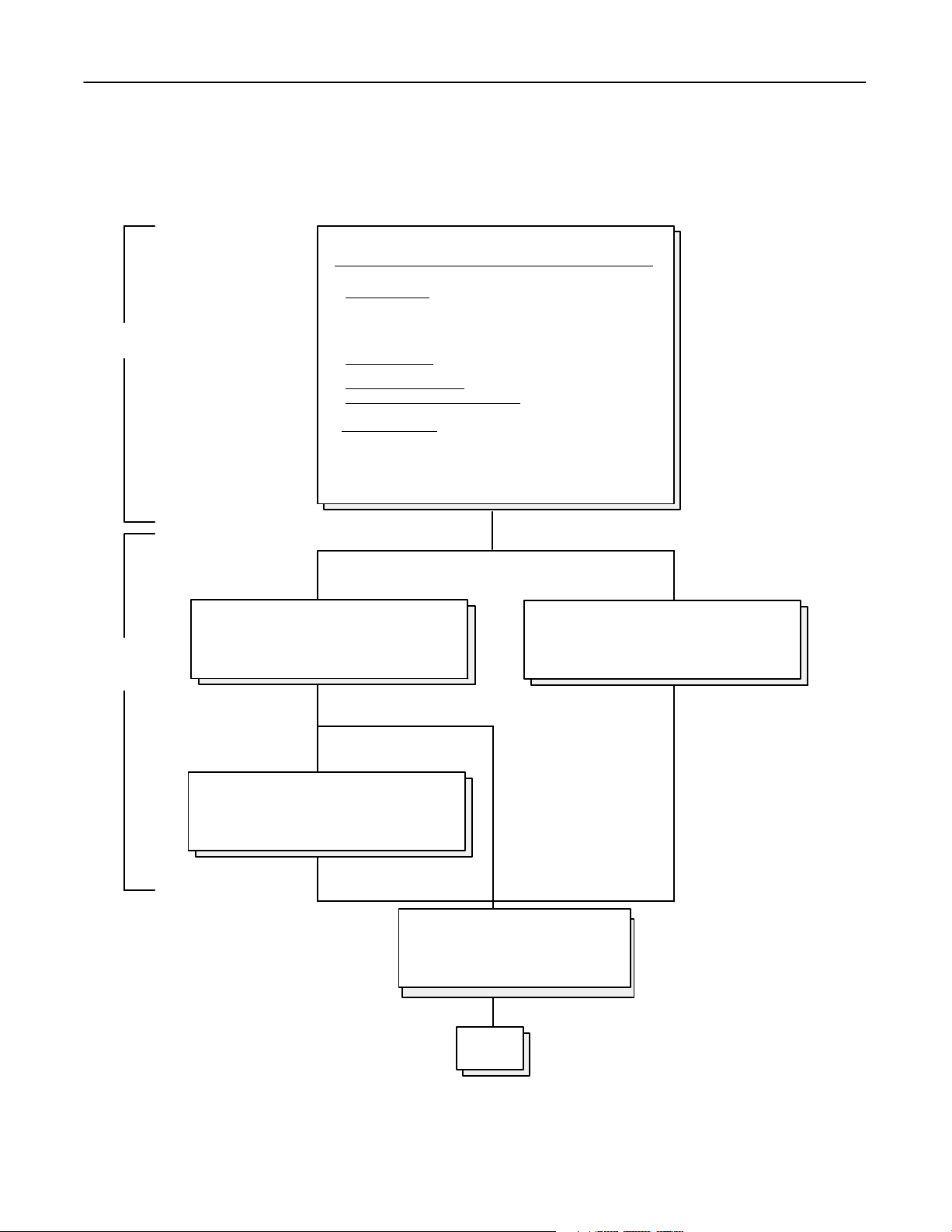
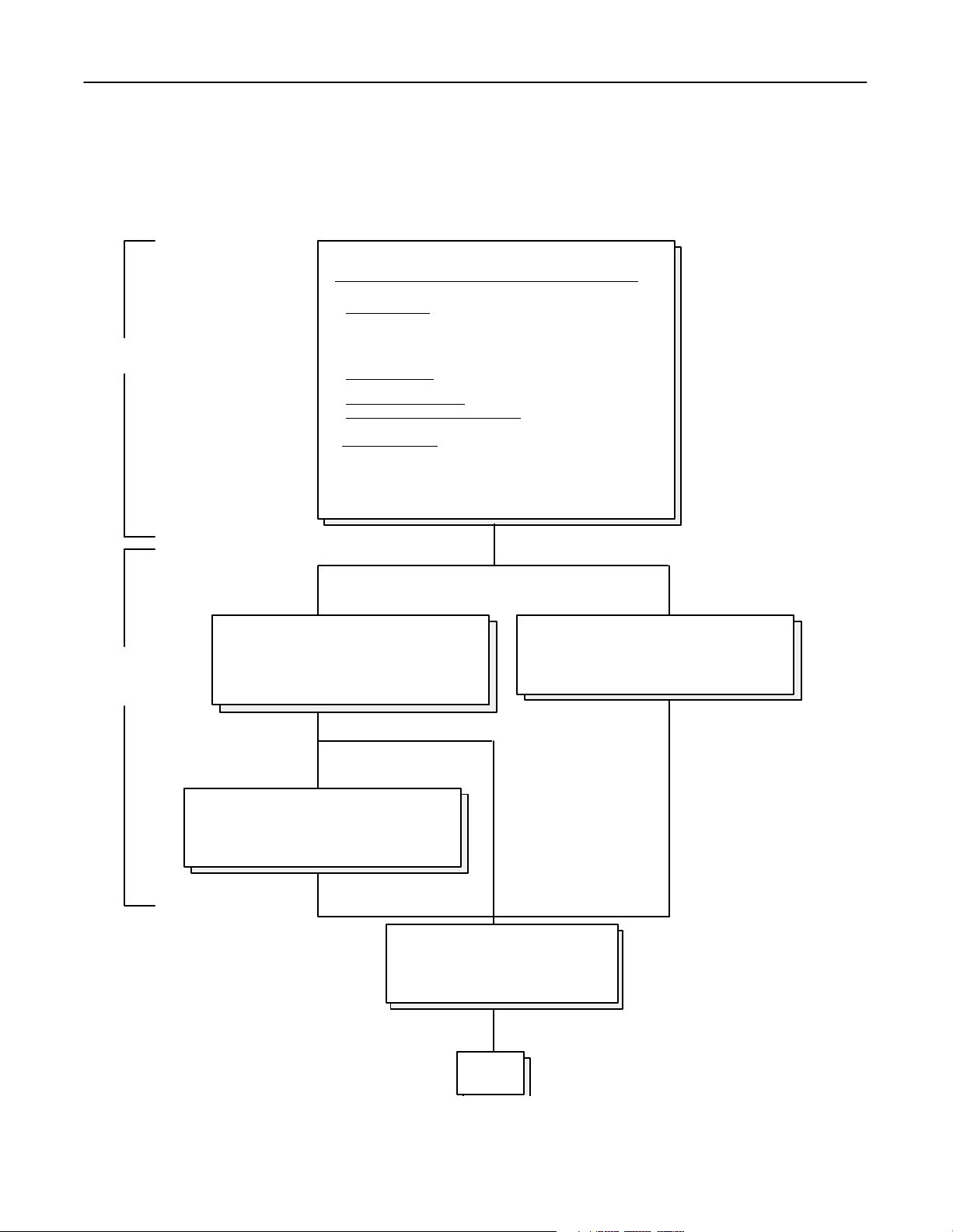
1-3 Manual System Composition
SYSTEM COMPAX 40E (Manual) with MPH 50/65/80
− COMPAX 40E
CLASSICAL RAD TABLE with Anticollision Kit
Core
− MPH 50/65/80
− High Speed Starter
− High Impedance Adaptation
Table Bucky with Grid & Ion Chamber
with AEC
To change mode
Optional
Features
− Power Supply:
XT SUSPENSION Inboard or Outboard with:
− HV cables + Stator and Collimator cables
− Manual Ultranet SM Collimator
− Maxiray 100 Tube
Tomo−Link
− Adapting kit for 40E
380Vac....480Vac (+/− 10%)
RST+GND
50/60 Hz
RS 85 TUBE STAND: with:
− Manual Collimator Ultranet SM
− Maxiray 100 Tube
SG 60/100 Vertical Bucky Stand
Right or Left hand
Grid & Ion Chamber
END
6
Page 18
System Service Manual − SYSTEM COMPAX 40E, CE Marked
GE HEALTHCARE with MPH 50/65/80 (including XT, RS 85 and Tomo−Link)
REV 9 DIRECTION 2154260−100
1-4 Automatic System Composition
SYSTEM COMPAX 40E (Auto) with MPH 50/65/80
− COMPAX 40E
CLASSICAL RAD TABLE with Anticollision Kit
Core
− MPH 50/65/80
− High Speed Starter
− High Impedance Adaptation
Table Bucky with Grid & Ion Chamber
with AEC
To change mode
Optional
Features
− Power Supply:
XT SUSPENSION Inboard or Outboard with:
− HV cables + Stator and Collimator cables
− Auto Ultranet SA Collimator
− Maxiray 100 Tube
− RAFL−S Collimator Control
Tomo−Link
− Adapting kit for 40E
380Vac....480Vac (+/− 10%)
RST+GND
50/60 Hz
RS 85 TUBE STAND: with:
− Auto Collimator Ultranet SA
− Maxiray 100 Tube
− RAFL−S Collimator Control
SG 60/100 Vertical Bucky Stand
Right or Left hand
Grid & Ion Chamber
END
7
Page 19

System Service Manual − SYSTEM COMPAX 40E, CE Marked
GE HEALTHCARE with MPH 50/65/80 (including XT, RS 85 and Tomo−Link)
REV 9 DIRECTION 2154260−100
THIS PAGE INTENTIONALLY LEFT BLANK.
8
Page 20

System Service Manual − SYSTEM COMPAX 40E, CE Marked
GE HEALTHCARE with MPH 50/65/80 (including XT, RS 85 and Tomo−Link)
REV 9 DIRECTION 2154260−100
CHAPTER 2 − INSTALLATION
SECTION 1
OVERVIEW
1-1 Foreword
teHLA (High Level Assembly) Program: There are two different versions of equipment shipped to the
customer, a non HLA or an HLA version.
COMPAX 40E SYSTEMS are fully assembled and calibrated at the factory (*) before shipment. Only
Tables purchased as add−ons to existing tables are non−HLA.
The aim of this factory integration, or High Level Assembly Program, is to improve the general quality of
the installation procedure on site while decreasing the installation time.
Program results:
− Increased customer satisfaction by reducing the equipment installation time and an increased
reliability and performance from its first use.
− Facilitate the technician’s work:
> by relieving him of time−consuming, tricky and repetitive jobs.
> by involving technicians in this new global process which consists of reducing installation time
and the global quality improvement of our equipment.
This reduces work load and warranty cost.
The Installation Steering Guide which follows is conceived to take maximum advantage of this High
Level Assembly program.
To avoid any duplication of information given in other documents, this manual makes a number of cross
references to Service or Installation Manuals specific to the various components that make up the system.
Any remarks improving the contents of this document would be appreciated.
(*) COMPAX 40E Systems for the US are factory checked with a XT “tool” since the suspension
is purchased locally.
9
Page 21
System Service Manual − SYSTEM COMPAX 40E, CE Marked
GE HEALTHCARE with MPH 50/65/80 (including XT, RS 85 and Tomo−Link)
REV 9 DIRECTION 2154260−100
1-2 Unpacking
1-2-1 Receipt of Equipment
HANDLING PACKED SUB−ASSEMBLIES
Prior to installation, store the equipment in its original packing, and handle it with care.
Do not drop, throw or stamp packages containing equipment or parts of it.
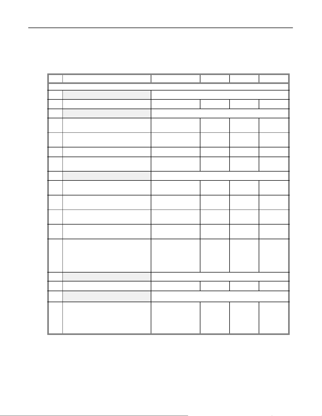
1-2-2 Inventory
Depending on the equipment ordered, check the number of packages delivered to the installation site.
The lists of packages hereafter do not include the optional components.
Crate Contents Dimensions Gross Weight
kg lb
N° 1
Compax 40E CE Table base including:
230x130x31 350 770
− Medys Bucky
− BVM Ion Chamber
− Telescopic Covers
− Compax 40E Documentation
− System Inspection Report
− System Cables
− Packing List
N° 2
Compax 40E CE Table Top
− Sensing Size Tray
150x94x103 75 165
10
Page 22

System Service Manual − SYSTEM COMPAX 40E, CE Marked
GE HEALTHCARE with MPH 50/65/80 (including XT, RS 85 and Tomo−Link)
REV 9 DIRECTION 2154260−100
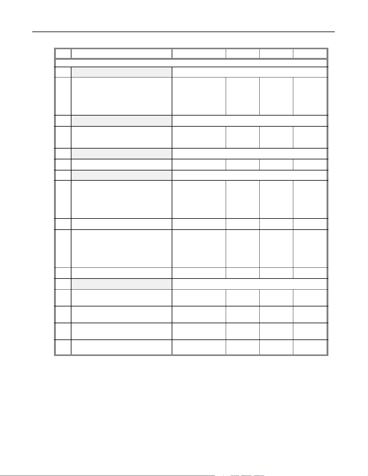
Crate Contents Dimensions
N° 3
MPH Cabinet including:
215x100x47 280 616
− I/F Room
− RAD Option
− HV Tank
− RAFL−S Collimator Control (optional)
− System cables
− C40E/MPH/XT/RS 85/SG SSM
(System Service Manual)
− Inspection Report
N° 4
MPH Console including:
72x120x62 50 110
− Program−X
− Hand Switch
− MPH Generator Documentation
− Packing List
N° 5
X−Ray Tube (Maxiray 100)
50x84x60 46 100
− X−ray Tube Unit
− Documentation
Gross Weight
kg lb
N° 6
N° 7
N° 8
GEMS−AM
delivered
systems
only
Ultranet SA Collimator or Ultranet SM Collimator
− Collimator Head
− Documentation
− Tools
SG60 or SG100 Vertical Bucky Stand including:
− Medys Bucky
− BVM Ion Chamber
− Size Sensing Tray
− SG60 or SG100 Documentation
− Packing List
− System cables
Tomo−Link
NOTE: In GEMS−AM delivered systems, the XT suspension
is shipped separately
47x39x56 30 66
230x87x86 288 633
109x82x88 98 216
11
Page 23

System Service Manual − SYSTEM COMPAX 40E, CE Marked
GE HEALTHCARE with MPH 50/65/80 (including XT, RS 85 and Tomo−Link)
REV 9 DIRECTION 2154260−100
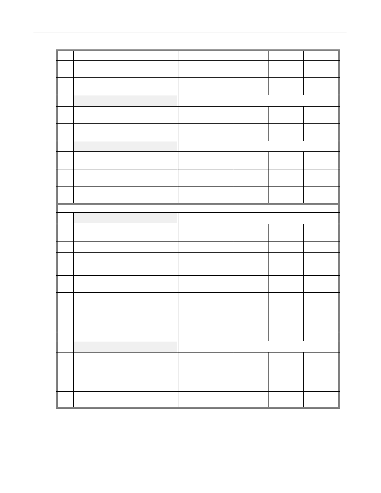
Crate Contents Dimensions
N° 8
GEMS−E
and
GEMS−A
delivered
systems
only
N° 9
GEMS−E
and
GEMS−A
delivered
systems
only
N° 10
GEMS−E
and
GEMS−A
delivered
systems
only
XT Suspension including:
− Covers and Accessories
− Documentation
NOTE: In GEMS−AM delivered systems, the XT suspension
is shipped separately
XT Suspension Bridge
NOTE: In GEMS−AM delivered systems, the XT suspension
is shipped separately
Inboard Concealment 60’ Cables for MPH Generator
including: TBC
− HV Cables
− Stator Cable
− Suspension Cables
NOTE: In GEMS−AM delivered systems, the XT suspension
106x90x152 276 607
318x82x48 140 308
214x30x61 109 240
is shipped separately
N° 11
GEMS−E
and
GEMS−A
delivered
systems
only
Stationary Rails
NOTE: In GEMS−AM delivered systems, the XT suspension
is shipped separately
476x18x12 48 100
Gross Weight
kg lb
N° 12
GEMS−E
and
GEMS−A
delivered
systems
only
Tomo−Link
NOTE: In GEMS−AM delivered systems, the XT suspension
is shipped separately
109x82x88 98 216
12
Page 24
System Service Manual − SYSTEM COMPAX 40E, CE Marked
GE HEALTHCARE with MPH 50/65/80 (including XT, RS 85 and Tomo−Link)
REV 9 DIRECTION 2154260−100
Crates N° 1 thru N° 7 are the same for both XT suspension and RS 85 Tube Stand Systems
Crate Contents Dimensions
N° 8
RS 85 Tube Stand including:
320x66x56 190 396
Gross Weight
kg lb
− Documentation
RS 85 Interface Package for Compax 40E System including:
− Set of System cables
− Documentation
N° 9
Accessories 47x39x56 30 63
Nº 10 Print−X (Option)
− Pedestal box
− Documentation
380 x 820 x 350 20 51
13
Page 25

System Service Manual − SYSTEM COMPAX 40E, CE Marked
GE HEALTHCARE with MPH 50/65/80 (including XT, RS 85 and Tomo−Link)
REV 9 DIRECTION 2154260−100
1-2-3 Unpacking
Damage Due to Transport
On delivery of the equipment, all packages must be checked to make sure that they have not been
damaged during transport.
If damage is observed, notify the transport service and the factory transport insurance service
immediately.
The above also applies for non apparent damage due to transport discovered when unpacking the
material or during installation, WITHIN 14 DAYS MAXIMUM AFTER DELIVERY.
Generally, a transport service will not pay a bill for non−apparent damage unless an expert’s report has
been requested within 14 days of delivery.
If damage is discovered, contact the concerned services immediately, specifying the type of apparatus,
the serial number and the order number if possible, as well as a description of the damage.
Unpacking and Inspection
Tools required for unpacking:
− a tool for removing nails, i.e. claw−hammer.
− a crowbar (minimum length 600 mm).
− a dolly for lifting and transporting the table base and SFD−fork, etc...
The components are wrapped in protective material and immobilized in the transport boxes. Each box is
numbered.
When unpacking, first find the packing list and check that all items are present. Check also that there is
no damage to the components received.
In case of missing parts, file a claim immediately mentioning the serial number of the unit as well as all
the shipping data.
Do not discard packing materials, such as envelopes or boxes, until all parts are accounted for.
− Do not place equipment cabinets in areas that are damp, poorly ventilated, too far from the console,
or on another floor.
− Avoid poor floor anchoring.
− Ensure that the screws and washers of each cover are inside plastic bags stuck on the inside of the
cover.
14
Page 26
System Service Manual − SYSTEM COMPAX 40E, CE Marked
GE HEALTHCARE with MPH 50/65/80 (including XT, RS 85 and Tomo−Link)
REV 9 DIRECTION 2154260−100
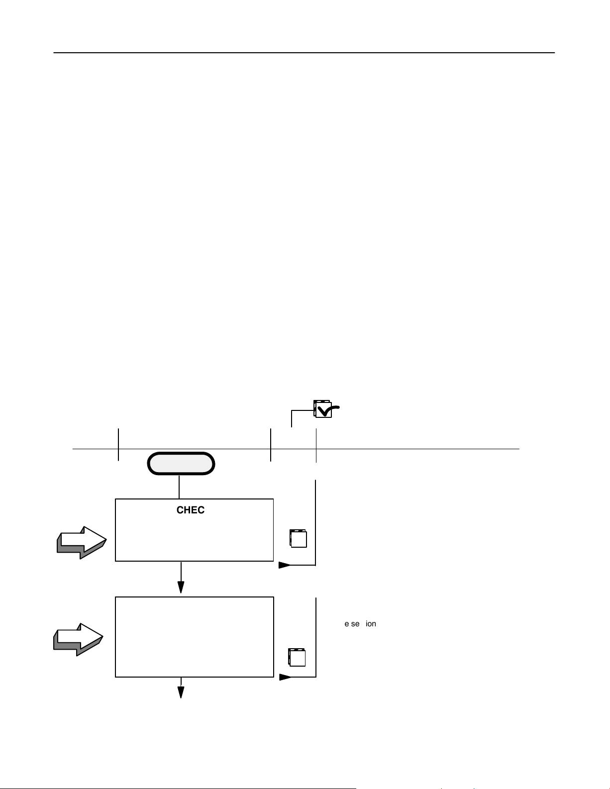
1-3 Installation Steering Guide
Note: Read the following paragraphs carefully before continuing with this Steering Guide.
• Pre−installation: Pre−installation work is required to prepare the room for installing the
equipment. Check that this work is complete, if not, complete
pre−installation work now.
• Inspection Report: Some of the Steering Guide steps are factory performed. Refer to Inspection
Report Dir. 2167647 TDR, 2172166 TDR or 2179651 TDR(supplied with the
system) to know exactly which steps have already been performed.
• Steering Guide: Some steps of the Steering Guide refer to other Service Manual chapters.
When each task is performed, return to the Steering Guide and proceed with
the next step.
• Clamping: Do not forget to clamp the system cables for EMC compliance. Refer
to Job Card IST 005.
• Pinning: To facilitate critical realignment on−site, several sub−assemblies are
pre−drilled and pinned or marked during factory integration. Refer to Job
Cards IST001, IST002, IST003 and IST 004 for installation procedures
The Undertable configuration comes with several system cables
pre−installed in the Table Rolling frame. The remaining system cables are
pre−installed in the Tubestand assy. Take care not to damage these cables.
Step
A1
A2
Data Base Backup: Performed by Manufacturing on Xamine Calibration Diskette.
Mark each box when task is done
Description Done
Supporting Documents
START
See PRE−INSTALLATION MANUALS
and LOCAL LAYOUT DATA Compax 40E CE, PIM
CHECK
Pre−installation Requirements
are met
1 person
1 Hour
Dir. 2150306−100
Vertical Bucky Stand CE, PIM Dir 2150305−100 (SG100),
Dir 2150301−100 (SG60)
MPH50/65/80, PIM Dir 2133000−100
XT CE, PIM Dir 46−019618
RS 85 CE, PIM Dir 2172805−100
UNPACKING
Collect the Product Locator cards
in sequential order
Localize Installation Flowchart
See section 1-2-3 of this manual.
Refer to Installation Flowchart for typical
main task durations
2 people
Continues on next page
4 Hours
15
Page 27
System Service Manual − SYSTEM COMPAX 40E, CE Marked
GE HEALTHCARE with MPH 50/65/80 (including XT, RS 85 and Tomo−Link)
REV 9 DIRECTION 2154260−100
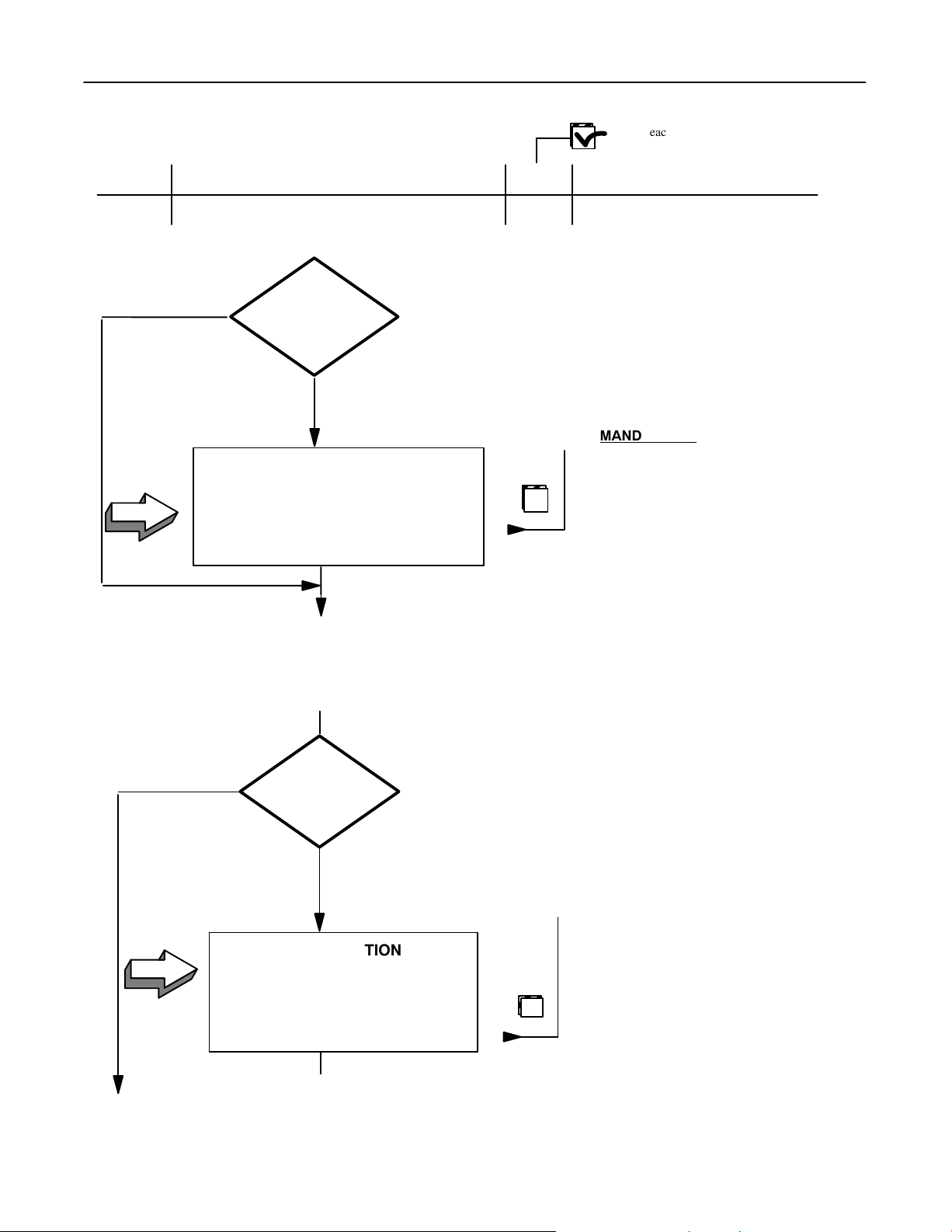
Mark each box when done
Step Description Done
From previous page
No
Pilot
System
Yes/No
Yes
FEEDBACK FORMS
A3
PGS 017 (Appendix 2)
1 Person
1 Hour
Supporting Documents
MANDATORY: Fill out this Pilot
Feedback Form in English
throughout the System installation
process.
This General Service Procedure PG017 is
available for GEMSE at local GE offices
PHYSICAL INSTALLATION OF SYSTEM COMPONENTS
XT INSTALLATION
Without XT
A4
XT Ceiling Suspension
Horizontal SID Sensors
2 people
Continues on next page
XT
with/without
With XT
INSTALLATION
If present, the ceiling suspension must be
installed first: carefully follow instructions
given in XT SM, Dir 2118733−100;
Chapter 3 or 4 (Do not install covers now)
16
Page 28
System Service Manual − SYSTEM COMPAX 40E, CE Marked
Í
GE HEALTHCARE with MPH 50/65/80 (including XT, RS 85 and Tomo−Link)
REV 9 DIRECTION 2154260−100
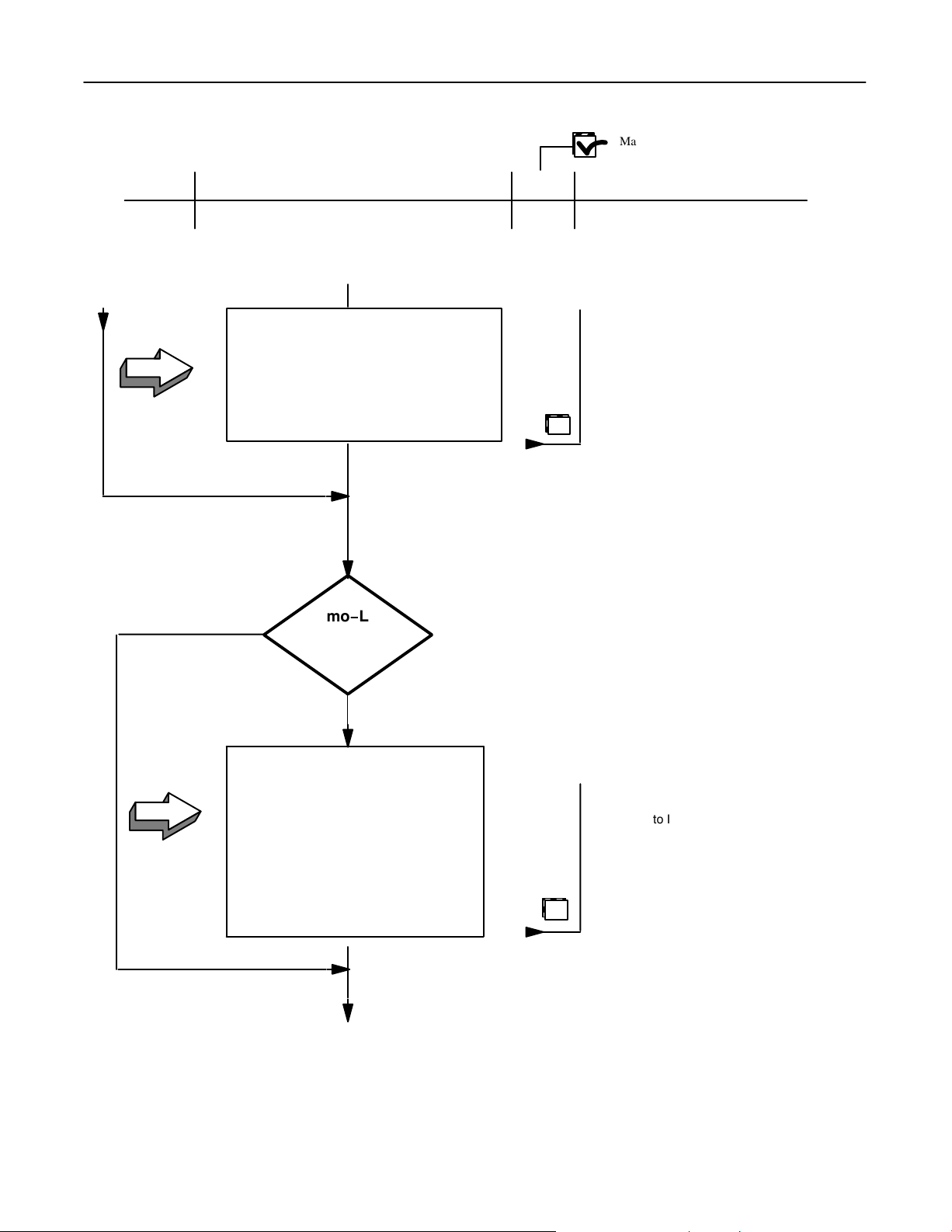
Mark each box when done
Step Description Done
From previous page
INSTALLATION
A5
X−Ray Tube
Collimator Head (SA/SM)
2 people
A4 − A5=16 Hours
Without
Tomo−Link
Supporting Documents
Refer to Inspection Report 2179651 TDR
or 2167647 TDR, sections 2.1 and 3.1
CAUTION: X−Ray Tube and Collimator
are factory aligned and assembled during
HLA.
The mounting ring should be not be
adjusted during installation .
See Job Card IST001 of this manual for
X−Ray Tube and Collimator installation
and levelling.
A6
with/without
With
INSTALLATION
Drive Unit
Yoke
Fulcrum Arm Support (Wall)
Operator Control Console
2 People 8 Hrs
Continues on next page
Refer to Inspection Report 2179651 TDR,
section 5.1
Refer to Tomo−Link SM 2133821−100
sections 1,2,5
17
Page 29
System Service Manual − SYSTEM COMPAX 40E, CE Marked
GE HEALTHCARE with MPH 50/65/80 (including XT, RS 85 and Tomo−Link)
REV 9 DIRECTION 2154260−100
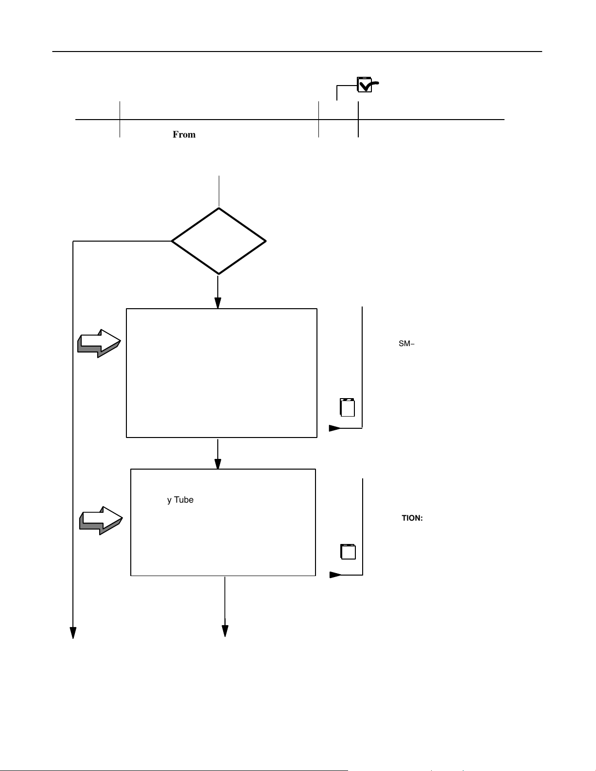
Step
Description Done
From previous page
RS 85 INSTALLATION
without
RS 85
with/without
with
INSTALLATION
A7
Column Cables Wall Box
Tube Stand Rail
Column With Carriage
Tube Support Arm
Counterweights
Supporting Documents
If present, RS 85 Tube Stand must be
installed first. Follow instructions given in
RS 85 PIM, Dir 2172805−100, Chapter 2.4
Refer to Inspection Report 2172166 TDR,
sections 1.1 and 1.2
See SM− RS 85 Dir. 0327 7223
Mounting Instructions Chapter 1 Section
1.6.1 (Overall dimensions) and:
Chapter 2, Section 2.3 (Adjust floor rails)
Chapter 2, Section 2.4
Chapter 2 sections 2.5 thru2.6
A8
2 People
INSTALLATION
X−ray Tube with Adapter
Collimator Assembly
HV Cable Routing
H
2 People
Continues on next page
XXHrs
Refer to Inspection Report 2172166 TDR,
sections 3.1 and 2.1
See SM− RS 85 Dir. 0327 7223
Installation & Service Instructions
CAUTION: X−Ray Tube and Collimator are
factory aligned and assembled during HLA.
The mounting ring should be not be
adjusted during installation .
See Job Card IST003 of this manual
HANDLE with CARE (by the support only).
18
Page 30
System Service Manual − SYSTEM COMPAX 40E, CE Marked
GE HEALTHCARE with MPH 50/65/80 (including XT, RS 85 and Tomo−Link)
REV 9 DIRECTION 2154260−100
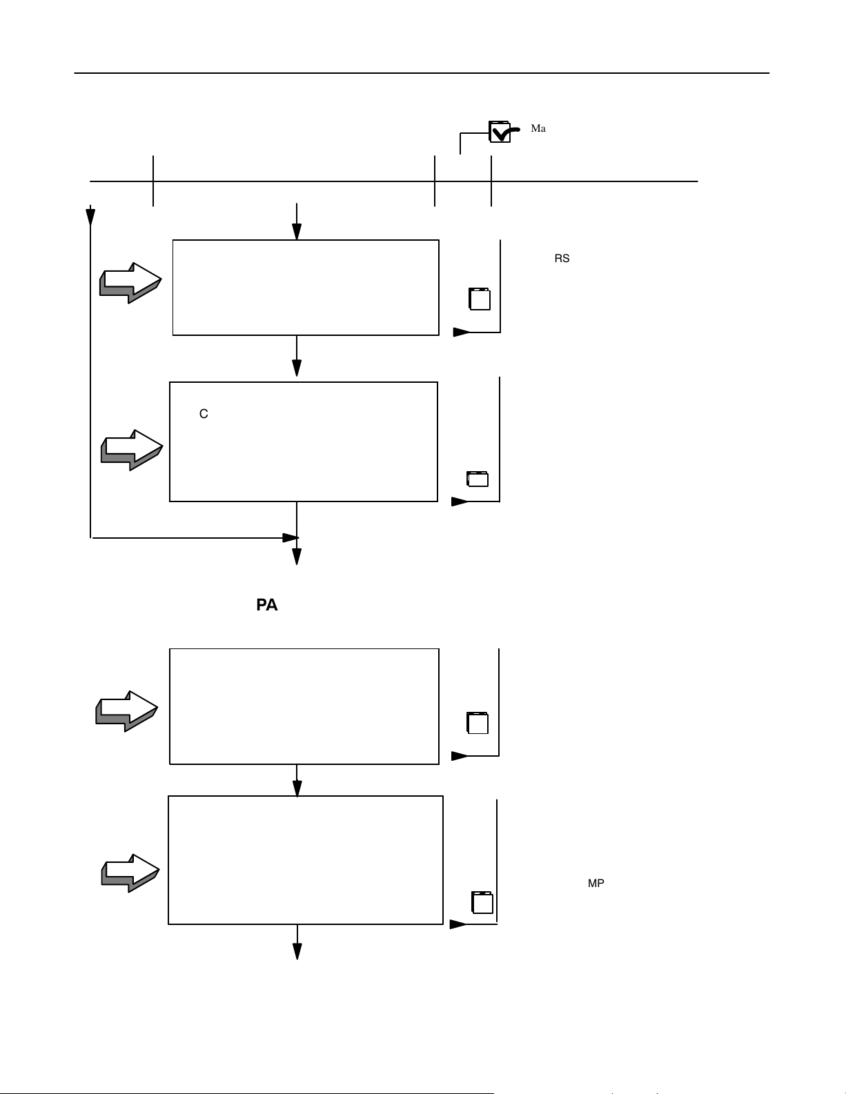
Mark each box when done
Step
A9
A 10
Description Done
From previous page
INSTALLATION
Counterbalancing & Leveling
1 Person
CONNECTIONS
Collimator cable
Lock Cable
Column Cable concealment
1 Person
A7 − A10= 8 Hours
Supporting Documents
See RS 85 Mounting Instructions, SM Dir.
0327 7223. Chapter 1, Section 1.7, Chapter
2 section 2.9 and Chapter 3 sections 3.1
thru 3.3 and 3.5.
REMARK: Most of these cables are already
factory connected.
See RS 85 Interface Kit for Compax 40E CE;
SM Dir.2165897−100, Chapter 1 Installation,
Chapter 2 MIS MAP and Chapter 3 MIS
CHART
See Job Card IST 005 for cable clamping
See MIS MAPS, Chapter 5 of this manual, and
MIS CHART in section 1-4-3 this chapter.
MIS No. 27304
See Job Card IST003 for Cable concealment
A 11
A12
COMPAX 40E TABLE INSTALLATION
INSTALLATION
Table Base Installation and leveling
Tabletop Installation
2 People
ALIGNMENT
Table Base Longitudinal Axis Alignment with:
XT Longitudinal Rails
(or) RS 85 Longitudinal Rails
2 People
Continues on next page
A11 − A12 = 4 Hours
Refer to Inspection Report 2179651 TDR
or 2167647 TDR sections 4.1 and 4.3
or
Inspection Report 2172166 TDR
sections 4.1 and 4.8
See SM COMPAX 40E CE, Dir. 2150299−100,
Chapter 1, Section 3.
NOTE: Precise alignment is extremely
important for Tomographic Performance.
See SM COMPAX 40E CE, Dir. 2150299−100,
Chapter 1, Section 3.2
19
Page 31

System Service Manual − SYSTEM COMPAX 40E, CE Marked
GE HEALTHCARE with MPH 50/65/80 (including XT, RS 85 and Tomo−Link)
REV 9 DIRECTION 2154260−100
Mark each box when done
Step Description Done
From previous page
WALL BUCKY INSTALLATION
A17
without
without
WALL
BUCKY
with/without
with
WALL
MOUNTING
KIT
with
Supporting Documents
See SM Vertical Bucky Stand SG 100 CE −
Dir 2150297−100, Chapter 1 or SM Vertical
Bucky Stand SG60, Dir 2150293−100
Chapter 1.
REMARK: Use of the Wall Mounting Kit is optional
but strongly recommended with certain kinds of
Hospital wall construction (Unistrut wall). Refer to
SG60 PIM 2150301−100 or SG100 PIM 2150305−100
.
A16
A17
INSTALLATION
Mounting Hardware Kit
1 Person
2 Hours
INSTALLATION
SG60/SG100 Installation
Vertical Leveling
Route System Cables from SG to MPH
Cabinet location
Lateral alignment across the wall to Table
Longitudinal Axis
2 People
2 Hours
Continues on next page
See SG60 SM 2150293−100, Job Card IST001
or SG100 SM 2150297−100, Job Card IST001
Refer to Inspection Report 2179651 TDR
or 2172166 TDR sections 6.1, 6.2 and 6.3
or
Inspection Report 2167647 TDR,
sections 5.1, 5.2 and 5.3
REMARK: Most of these cables are already factory
connected. See MIS MAP / MIS CHART of this
Manual (section 1−4)
.
Connections to be done during Installation:
SG60: MIS 5.1
SG100: MIS 5.1−9
20
Page 32

System Service Manual − SYSTEM COMPAX 40E, CE Marked
Í
GE HEALTHCARE with MPH 50/65/80 (including XT, RS 85 and Tomo−Link)
REV 9 DIRECTION 2154260−100
Mark each box when done
Step Description Done
From previous page
MPH SYSTEM CABINET INSTALLATION
INSTALLATION
Cabinet Positioning
A18
A19
Cabinet Securing
2 People
CONFIGURATION
Generator Power Connection
Line Voltage and Frequency:
Dependent Settings
AC Voltage Supply for Buckies
*,
XT
RS85 Power Supply*
1 Person
2 Hours
*
1 Hour
Supporting Documents
See Pre−installation Manual (Layout).
See SM MPH 50/65/80 dir. 2137354−100,
Chapter 1 Installation ; section 2,
Job Card IST002. Use Securing Kit (Part
2175309 provided with Upper Cabinet
REMARK:Verify PCB have not moved
during transportation, particularly the
Power PCB in RAFL−S rack.
If the Wall Attachment Kit* is available, follow
instructions supplied with the Kit *(Part #
Refer to Inspection Report 2179651 TDR or
2167647 TDR, section 1.2 and 3.3
or
Inspection Report 2172166 TDR, section 1.2
and 3.4
See SM MPH Dir 2137354−100, Chapter 1,
Installation: section 2, Job Card IST002
WARNING
1. Refer to Inspection Report and/or to orange
2. With MPH the XT is ALWAYS powered with
3. XT is shipped separately for the US.
2164271, S16201EB)
MAINLY FOR USE IN THE USA:
labels fixed to the buckies
230VAC.
Default setting is 110V.
Refer to XT Service Manual Dir
2118733−100 for 220V setting.
A20
INSTALLATION
Console Generator
PRINT−X Console (option)
PROGRAM−X (option)
1 Person
Continues on next page
Refer to Inspection Report 2179651 TDR or
2172166TDR or 2167647 TDR, section 1.1
See Pre−Installation manual (layout).
See SM MPH 50/65/80 dir. 2137354−100, Chapter 1
Installation; section 2, Job Card IST002.
PRINT−X
1 Hour
CAUTION: Ensure proper tightening of wire
connections and setting of connectors
21
Page 33

System Service Manual − SYSTEM COMPAX 40E, CE Marked
Í
GE HEALTHCARE with MPH 50/65/80 (including XT, RS 85 and Tomo−Link)
REV 9 DIRECTION 2154260−100
Mark each box when done
Step Description Done
From previous page
SYSTEM CONNECTIONS
POWER AND GROUND
CABLE CONNECTIONS
POWER WIRING CONNECTIONS
A21
Route Power and Ground cables
Connect cables onto MPH
2 People
Supporting Documents
Refer to Inspection Report 2179651 TDR or
2172166 TDR or 2167647 TDR, section 1.2
REMARK: Most of these cables are already factory
connected. See MIS MAP / MIS CHART of this
Manual (section 1−4)
.
Connections to be done during Installation:
MIS 3, 4, 6, 9, 11
MIS 1−1, 21, 3−1, 4−1, 5−1, 6−1, 7.1
See SM MPH: Dir 2137354−100
Chapter 1, Job Card IST002
A22
SYSTEM CABLES CONNECTION
SYSTEM WIRING CONNECTION
Route remaining System cables
2 People
Continues on next page
A21 − A22 = 4 Hours
22
REMARK: Most of these cables are already factory
connected. See MIS MAP / MIS CHART of this
Manual (section 1−4)
.
Connections to be done during Installation:
MIS 1, 2, 6, 7, 8, 10, 12 to 23
NOTE: For connection of DOOR OPEN switch
and EXPOSURE ON signal lamp refer to Jov
Card IST004 of this manual
See Job Card IST 005 for cable clamping
Page 34

System Service Manual − SYSTEM COMPAX 40E, CE Marked
GE HEALTHCARE with MPH 50/65/80 (including XT, RS 85 and Tomo−Link)
REV 9 DIRECTION 2154260−100
Mark each box when done
Step Description Done
Supporting Documents
From previous page
WARNING
MAINLY FOR USE IN THE USA:
*
• For Bucky: refer to Inspection Report 2179651
TDR, section, 4.2 for 40E, section 6.3 for SG
or to Inspection Report 2167647 TDR or
2172166 TDR, section 4.2 for 40E; section
5.3 for SG
Refer also to orange label fixed to the Bucky
See IST 004
A23
CONFIGURATION CHECK
Bucky Voltage Settings:
110 or 220AC for SG60−100 Bucky
110 or 220AC for Compax 40E Bucky
220V for XT Suspension, RS85, C40E,
TLK, SG
• For components: refer to Inspection Report
1 Person
VERY IMPORTANT: Read Inspection Report (IR) ( Dir. 21722166TDR for Compax 40E/MPH/SG/RS 85; Dir.
2167647TDR for Compax 40E/MPH SG/XT; Dir. 2179651TDR for Compax 40E/MPH/SG/Tomo−Link) through
carefully before eventually proceeding with the MPH software configuration, Step A24 of this Steering Guide.
2179651 TDR or 2167647 TDR or 2172166
TDR
POWER ON AUTHORIZED
CALIBRATION OF SYSTEM COMPONENTS
IR
meets
expectations?
Yes
No
Continues on next page
If more reconfiguration is necessary, proceed to step A24
Reconfiguration is complete.
23
Page 35

System Service Manual − SYSTEM COMPAX 40E, CE Marked
GE HEALTHCARE with MPH 50/65/80 (including XT, RS 85 and Tomo−Link)
REV 9 DIRECTION 2154260−100
Mark each box when done
Step
A24
Description Done
From previous page
MPH CONFIGURATION CHECKS
CONFIGURATION
Re−do MPH necessary Configuration
1 Person
CONFIGURATION
Supporting Documents
Refer to Inspection Report 2179651 TDR or to
Inspection Report 2167647 TDR, or 2172166 TDR
section 1.3
See MPH SM 2137354−100, Job Cards
LG001, RG001 and RG002
NOTE: Connect Service Terminal as described
Refer to Inspection Report 2167647 TDR, or 2172166 TDR
section 4.3 for C40E; section 5.3 for SG; section 6.2 for
RAFL−S
or
Refer to Inspection Report 2179651 TDR, section
4.3 for 40E; 6.3 for SG; 7.2 for RAFL−S
in Job Card LG 001
A25
A26
D Re−do necessary Sub−System
Components Configuration
1 Person
RUN−IN & STABILITY CHECK
Rotating anode Tube
1 Person
Continues on next page
See C40E SM 2150259−100 (Chapter 2)
SG60 SM 2150258−100 (Chapter 2), SG100 SM
2150257−100 (Chapter 2), XT SM 46−019803 or
2118910−100 (section 12), RS 85 SM Mounting
Instructions 0327 7223 (section 3)
Refer to Inspection Report 2179651 TDR or Inspection
Report 2167647 TDR, or 2172166 TDR section 2.2
REMARK: The Run−in & Stability check is
performed at the factory. See Technical
Publications, Dir. 46−013804
1 Hour
To redo on site ONLY if necessary (refer to
System Inspection Report Completion date).
Use procedure for MVP generators.
24
Page 36

System Service Manual − SYSTEM COMPAX 40E, CE Marked
GE HEALTHCARE with MPH 50/65/80 (including XT, RS 85 and Tomo−Link)
REV 9 DIRECTION 2154260−100
Mark each box when done
Step Description Done
From previous page
MPH CALIBRATION
Yes
kV, mA, mAs
Calibration Checks
A27
1 Person
OK
1 Hour
No
Supporting Documents
REMARK: The MPH calibration is
performed at the factory but it is necessary
to re−check it.
Refer to Inspection Report 2167647 TDR or
2179651 TDR or 2172166 TDR.section 2.3
and proceed with required calibration
checks marked in grey:
Make several exposures at different kV, mA
and mAs stations. Read Post Display on
MPH Console and if out of range, proceed
to step A28 otherwise, skip to step A29
NOTE: kV must be measured using a
Keithley 3508 kV pic meter.
A28
CALIBRATION
Run necessary MPH Calibrations
1 Person
Continues on next page
XX Hrs
Refer to Inspection Report 2167647 TDR, or
2172166 TDR, section 2.2−2.3
Connect Service Terminal. Refer to the MPH
SM Dir. 2137354−100 Chapter 1 section 3
and proceed with calibrations in that section.
25
Page 37

System Service Manual − SYSTEM COMPAX 40E, CE Marked
GE HEALTHCARE with MPH 50/65/80 (including XT, RS 85 and Tomo−Link)
REV 9 DIRECTION 2154260−100
Mark each box when done
Step Description Done
From previous page
COMPAX 40E, XT, RS−85 CALIBRATION
(Factory Calibrated)
CALIBRATION
Perform necessary calibrations on:
A29
Compax 40E Table
XT Suspension
RS 85
1 Person
Supporting Documents
Refer to Inspection Report 2179651 TDR or
2167647 TDR, section 4.9 for 40E
and XT
Refer to Inspection Report 2172166 TDR,
section 4.10 for RS 85 and 40E
See SM COMPAX 40E− Dir. 2150299−100,
Chapter 3 − Calibration,
See SM. XT Radiographic Suspension Dir
2118733−100, Chapter 5 Service
Adjustments.
See RS 85 SM Mounting Instructions 0327
7223, section 3
A30
X−RAY BEAM ALIGNMENT/SID ADJUSTMENT
PERPENDICULAR ADJUSTMENT
Perpendicularity of X−Ray beam with
Table
Bucky Stand.
1 Person 1/2 Hour
Continues on next page
26
See C40E SM; Dir. 2150299−100
Chapter 3, section 3 (use RMI 161 B
tool)
Page 38

System Service Manual − SYSTEM COMPAX 40E, CE Marked
GE HEALTHCARE with MPH 50/65/80 (including XT, RS 85 and Tomo−Link)
REV 9 DIRECTION 2154260−100
Step Description Done
From previous page
CENTERING ADJUSTMENT
A31
X−ray beam and Light beam alignment check
Center X−Ray beam on Table
Center X−Ray beam on Bucky Stand
1 Person 1 1/2 Hours
SID DETENT ADJUSTMENT
(FINAL POSITIONING)
Horizontal SID Detent
Horizontal SID Detent
A32
Horizontal SID Indicators
1 Person
1/2 Hour
Supporting Documents
See Ultranet SA + RAFL−S sm
Dir. Y00W20L.04 or Ultranet SM sm
Dir. Y00W1L.04 Chapter 4.
See C40E SM: Dir 2150295−100,
Chapter 3, section
See XT SM Dir 46−019803, section 8
or Dir 2118910−100, section 12
or RS−85 SM Mounting Instructions
Dir. 2172805−100 Chapter 2.
and RS 85 Interface SM 2165897−100,
Chapter 1, section 5.
A33
COLLIMATOR CALIBRATION
VERIFICATION
(SA or SM) Collimator lamp voltage
1 Person
Continues on next page
1/2 Hour
Refer to Inspection Report 2179651 TDR or
2167647 TDR, section 3.3
or
Inspection Report 2172166 TDR section 4.7
−For XT see Job Card IST002
of this manual
−For RS 85 see Job Card IST003 of this
manual
27
Page 39

System Service Manual − SYSTEM COMPAX 40E, CE Marked
GE HEALTHCARE with MPH 50/65/80 (including XT, RS 85 and Tomo−Link)
REV 9 DIRECTION 2154260−100
Step Description Done
From previous page
Manual (SM)
Ultranet
Collimator
Auto/Manual
Auto (SA)
CALIBRATION
Ultranet SA Collimator + RAFL−S
A34
C40E
SG60/SG100
1 Person
2 Hours
Supporting Documents
Refer to Inspection Report 2179651 TDR,
section 7.3, or 2167647 TDR or 2172166 TDR,
section 6.3
Proceed with required calibrations labelled:
See ULTRANET SA + RAFL−S SM
Dir. Y00W20L.04, Chaps 3, 4 and 6.
(Use extension cable/support provided to
connect RAFL keyboard and fix it on front
of cabinet − Must be removed after the
CALIBRATION is completed).
See Job Card IST005 to open the
RAFL−S rack
A35
TOMO−LINK CALIBRATION
CALIBRATION
Perform C1, C2, C3, C4, C5 ,C7
Calibration Procedures
Drive Power amp adjustment
1 Person
Continues on next page
1 Hour
Refer to Inspection Report 2179651 TDR
section 5.2
See SM Tomo−Link Dir. 2133821−100,
Section 16 and 20.
28
Page 40

System Service Manual − SYSTEM COMPAX 40E, CE Marked
Í
GE HEALTHCARE with MPH 50/65/80 (including XT, RS 85 and Tomo−Link)
REV 9 DIRECTION 2154260−100
Step Description Done
From previous page
AEC CALIBRATION
FILM PROCESSING
Processor ready and operational
A36
Film/Screen characteristics defined
Film Image Quality available
CALIBRATION
Supporting Documents
NOTE: Film processor must be
fully operational at this stage to
proceed with AEC calibration.
Image quality tools (sensitometer,
etc.) must also be available.
A37
A38
AEC for Table Bucky Technique
AEC for Wall Bucky Technique
AEC for Tomo Technique
2 People
6 Hours
SID SCALES
POSITIONING
XT Suspension
RS 85 Tubestand
SG60/SG100
1 Person 1 Hour
See SM MPH 50/65/80, X−ray unit, Dir.
2137354−100, Chapter 1, Installation, Job
Card RG005.
XT: Refer to SM 2118733−100 Dir
46−019803, section 8.6
or Dir 2118910−100, section 12.6
RS−85: Refer to Interface SM
2165897−100 (Chapter 1, section 4 and 5)
SG60: Refer to SM 2150293−100
SG100: Refer to SM 2150297−100
Chapter 1, section 9
Continues on next page
29
Page 41

System Service Manual − SYSTEM COMPAX 40E, CE Marked
GE HEALTHCARE with MPH 50/65/80 (including XT, RS 85 and Tomo−Link)
REV 9 DIRECTION 2154260−100
Step Description
From previous page
FUNCTIONAL CHECKS
SYSTEM CHECKS
SYSTEM COMPONENT
FUNCTIONAL CHECKS
SG60/SG100
A39
Collimator SA/SM
Compax 40E
XT/RS 85
MPH 50−65−80
Tomo−Link
Program−X
2 People
4 Hours
Done
Supporting Documents
Refer to Inspection Report 2167647 TDR,
sections 1.2 & 1.5 (MPH), 4.11 (40E), 3.4
(XT/Collimator), 5.4 (SG60/100), 7 (general system
functional check)
or
Refer to Inspection Report 2179651 TDR,
sections 1.2 & 1.5 (MPH), 4.11 (40E), 3.4
(XT/collimator), 5.3 (Tomolink), 6.4 (SG60/100),
8 (general system functional check)
or
Inspection Report 2172166 TDR, sections 3.3
(RS 85/collimator), 4.12 (40E), 1.2 & 1.5 (MPH),
5.4 (SG60/100)
SG60/SG100 Dir 2150297−100
ULTRANET Collimator SM Dir.Y00W1L.04;
SM COMPAX 40E CE, Dir. 2150299−100,
Chapter 4, Section 3−4.;
XT sm Dir. 2118733−100;
RS 85 sm Mounting Instructions 03277223;
MPH SM Dir.2137354−100
SM ULTRANET SA & RAFL−S, Dir. Y00W20L.04,
Chapter 4;
SM Tomo−Link 2133821−100 (section 18)
A40
IMAGE QUALITY
CHECKS
SG60−100 Film Resolution
Tomo−Link Image Quality
40E Film Resolution
2 People 4 Hours
Continues on next page
Refer to SG60 SM Dir 2150293−100, Job Card
VF001,
SG100 SM Dir 2150257−100, Job Card VF001,
Tomo−Link SM Dir 2133821−100 section 18−10
Refer to 40E Service Manual 2150299−100,
Jobcard VF001.
30
Page 42

System Service Manual − SYSTEM COMPAX 40E, CE Marked
GE HEALTHCARE with MPH 50/65/80 (including XT, RS 85 and Tomo−Link)
REV 9 DIRECTION 2154260−100
Step Description Done
From previous page
HHS TEST (If Required)
Step A28
No
1 Person
Test
OK
Yes
4 Hours
Supporting Documents
Note: HHS test or any local, in−house,
regional or governmental acceptance tests.
NOTE: If your country requires the product
rating plate label to be in the language of that
country, follow the instructions on document
#45474336. Paste the appropriate language
label over the English rating plate. The rating
plate labels are: 2379361 (Spanish),
2379361−2 (German), 2379361−3 (French),
2379361−4 (Italian).
A41
COVER INSTALLATION
Compax 40E
SG60−100
Tomo−Link
MPH
XT Suspension
RS−85
2 People
Continues on next page
2 Hours
Refer to Inspection Report 2167647 TDR,
4.12 (40E) and 5.5 (SG60/100)
Refer to Inspection Report 2179651 TDR,
sections 4.12 (40E) and 6.5 (SG60/100)
Refer to Inspection Report 2172166 TDR,
sections 4.13 (40E) and 5.5 (SG60/100)
See SM COMPAX 40E CE, Dir. 2150299−100,
Chapter 1, Installation, Section 7.
See SM SG60 Dir 2150253−100 Chapter 1
See SM SG100 CE Dir 2150297−100 Chapter 1
See SM XT RADIOGRAPHIC SUSPENSION
Dir 2118733−100; Chapter 3 or 4, Installation.
MPH 50/65/80: See SM 2137354−100,
Job Card IST 002
Note: GRN wires must be connected to
metal covers when available.
31
Page 43

System Service Manual − SYSTEM COMPAX 40E, CE Marked
Í
GE HEALTHCARE with MPH 50/65/80 (including XT, RS 85 and Tomo−Link)
REV 9 DIRECTION 2154260−100
Mark each box when done
Step Description Done
From previous page
FINAL SYSTEM CHECKS
MOVEMENTS
A42
Compax 40E, SG60−100, XT, RS 85
X−Ray Tube Rotor noise
1 Person
1 Hour
MISCELLANEOUS
Supporting Documents
COMMENT: Check for any unusual noise
and on vibration during components
movement. Make appropriate corrections
A43
A44
PRODUCT LOCATOR
Please complete and send in cards to
Product Locator Administrator
1 Person
1 Hour
GIF & DOA
Please complete and send in green card
to GIF Administrator
DOA tag must be returned with parts
found Dead On Arrival
Continues on next page
Refer to COM 3.3 or COM 3.4 ISERV (on Profs)
for Administrator Contact
Refer to COM 3.3 or COM 3.4 ISERV (on Profs)
for more details.
32
Page 44

System Service Manual − SYSTEM COMPAX 40E, CE Marked
GE HEALTHCARE with MPH 50/65/80 (including XT, RS 85 and Tomo−Link)
REV 9 DIRECTION 2154260−100
Mark each box when done
Step
A45
Description
From previous page
PILOT SYSTEM ONLY
(PGS017 FORM)
Complete and return the PILOT FEEDBACK
FORM to USD/RAD (BUC)
Complete and return the Installation
Flowchart to ISS (BUC)
1 Person XX Hours
Done
Supporting Documents
Refer to PGS017 Form and to COM 3.3 or
COM 3.4 ISERV (on Profs) for USD Contact.
A46
SOFTWARE BACKUP
Record MPH set up parameters on the
calibration diskette
1 Person
END
Refer to MPH SM Dir. 2137354−100,
Job Card IST013
1/2 Hour
33
Page 45

System Service Manual − SYSTEM COMPAX 40E, CE Marked
GE HEALTHCARE with MPH 50/65/80 (including XT, RS 85 and Tomo−Link)
REV 9 DIRECTION 2154260−100
1-4 Cable Connections
1-4-1 Preliminaries
1. The following interconnection cable numbers refer to the MIS MAP and GROUNDING
INTERCONNECTING MAP included at the end of this manual.
2. The reference numbers between brackets ( ) refer to internal cables also described in the Service
Manuals.
1-4-2 Mis Chart
System MPH 50/65/80 with Compax 40E / SG 60 or SG100 / XT Suspension
Note: Some of the cables, or set cables, are factory connected at one end. In the following MIS Charts:
− Numbers on the left presented in grey squares are HLA numbers (CABLES #).
− The symbol is used to identify those connections which remain to be done during on site
installation.
− The symbol indicates where cable clamping is necessary (refer to Job Card IST006 of this Manual
for EMC rules requirements.
DO NOT FORGET TO CLAMP CABLES ENTERING THE MPH CABINET. IT IS
MANDATORY TO MAINTAIN THE SYSTEM EMC COMPLIANT.
34
Page 46

System Service Manual − SYSTEM COMPAX 40E, CE Marked
GE HEALTHCARE with MPH 50/65/80 (including XT, RS 85 and Tomo−Link)
REV 9 DIRECTION 2154260−100
CABLE #
TERMINALS
1
2
MPH A1 A2 MODULE
(Stator Connector
Panel)
3
MPH A6 A3 MODULE
(Distribution Board)
CAUTION
HV TANK
L
TUBE−I (+)
HV
MPH 50/65/80 CABINET
ANODE
TUBE−I (−)
CATHODE
XJ1A/B−1 TSxx−L
XJ1A/B−2
Ground Plug
ST1−1
ST1−3
ST1−5
ST1−7
ST1−10
ST1−11
ST1−12
Clamped
C
S
M
L
C
S
M
Black
White
Green
Brown
Blue
Orange
Yellow
Shield
120/240Vac
0Vac
Ground
VERIFY THE 240V XT POWER SETTING
MIS 107
46−195120G4
46−195120G4
MIS 10680
2128497
STATOR
CABLE
W34
2104204
PRINTER−X Power Supply
CABLE
X−RAY TUBE
L
C
ANODE
S
M
L
C
CATHODE
S
M
Black
White
Green
Brown
Blue
Orange
Yellow
Shield GND Screw
120/240Vac
0Vac
Ground
TSxx−N
GND STUD
(8)−Terminal Strip
(6)−Terminal Strip
(7)−Terminal Strip
(5)−Terminal Strip
(4)−Terminal Strip
(2)−Pressure Switch
(1)−Pressure Switch
PRINTER − X
MPH A9 MODULE
XT SUSPENSION
X−RAY TUBE HV
CONNECTIONS
X−RAY TUBE
(Maxiray−75/100)
4
MPH A1 MODULE
(AC Distribution
Panel)
F15−2
F14−2
Ground Plug
240V AC
0Vac
Gnd
MIS10707
XT Suspension Power Supply CABLE
46−329288G2
0Vac
jumper
Gnd
J100−12
J100−6
J100−5
J100−1
(Control Board 3A1)
J100−10
240Vac
35
Page 47

System Service Manual − SYSTEM COMPAX 40E, CE Marked
GE HEALTHCARE with MPH 50/65/80 (including XT, RS 85 and Tomo−Link)
REV 9 DIRECTION 2154260−100
CABLE #
5
MPH A1 A1 MODULE
(AC Distribution Panel)
MPH A7 MODULE
6
(Control Console)
7
MPH A6 A3 MODULE
(Distribution Board)
MPH 50/65/80 CABINET
TS−GND
(PU3) MADRID CONSOLE
XJ4−2
XJ4−3 MPH A9−3
XJ4−5
Connector Support
MPH 50/65/80 CABINET
XJ10−13
XJ10−32
XJ10−9
XJ10−24
XJ10−11
XJ10−30
XJ10−12
XJ10−31
XJ10−17
XJ10−18
XJ10−36
XJ10−37
Connectorsupport/clamp
XJ10−14
XJ10−15
XJ10−33
XJ10−34
XJ10−20
MIS 27235
P1
P2
P3
(OPTIONAL)
2138905
POWER SUPPLY CABLE
(2125971)
RX RX
TX
Gnd
Shield
Shield
Gnd
Gnd
5Vdc
TXA
TXB
RXA
RXB
19V
0 / 19V
PROGRAM−X Control CABLE
2125971
PRINTER−X Control CABLE
W32
2126153
Gnd
Gnd
5Vdc
TXA
TXB
RXA
RXB
19V
0 / 19V
Shield
Phase 1 (R)
Phase 2 (S)
Phase 3 (T)
GROUND
MPH A9−2
TX
Gnd
MPH A9−7
Shield
Connector Support
XJ1−4
XJ1−4
XJ1−24
XJ1−11
XJ1−30
XJ1−12
XJ1−31
XJ1−17
XJ1−18
XJ1−36
XJ1−37
XJ1−14
XJ1−15
XJ1−33
XJ1−34
XJ1−20
Connectorsupport/clamp
MAIN POWER
LINE SAFETY SWITCH
PRINTER−X
MPH A9 MODULE
(PU3) MADRID CONSOLE
MPH A8 MODULE
(Program−X Control)
8
MPH A6 A3 MODULE
(Distribution Board)
SG100 VERTICAL BUCKY STAND
9
I / O PANEL
XJ12−21
XJ12−22
XJ12−24
XJ12−25
XJ12−26
XJ12−27
XJ12−28
XJ12−29
XJ12−30
XJ12−31
clamp
TS2−L
TS2−N
GND STUD
FL switch 2
C. switch
OFF
ON
TXB cons.
RXB cons.
TXB TAV
RXB TAV
TXB print
RXB print
Shield
230Vac
O Vac
GND
2126152
CONSOLE Control CABLE
MIS 27225
2151729
SG100 Power Supply CABLE
36
(2126152)
FL switch 2
C. switch
OFF
ON
TXB cons.
RXB cons.
TXB TAV
RXB TAV
TXB print
RXB print
Shield
230Vac
O Vac
GND
XJ1−21
XJ1−22
XJ1−24
XJ1−25
XJ1−26
XJ1−27
XJ1−28
XJ1−29
XJ1−30
XJ1−31
clamp
F11−2
F10−2
Ground Plug
MPH A7 MODULE
(Control Console)
MPH A1 MODULE
(AC Distribution Panel)
Page 48

System Service Manual − SYSTEM COMPAX 40E, CE Marked
GE HEALTHCARE with MPH 50/65/80 (including XT, RS 85 and Tomo−Link)
REV 9 DIRECTION 2154260−100
CABLE #
10
MPH A6 A4 MODULE
(Wall Bucky Board)
CAUTION
11
MPH A1 MODULE
(AC Distribution Panel)
12
MPH A6 A5 MODULE
(Table Tomo Board)
CAUTION
MPH 50/65/80 CABINET
VERIFY THE BUCKY SUPPLY 115/240 SETTING
Ground Plug
VERIFY THE BUCKY SUPPLY 115/240 SETTING
O Vac
XJ3−7
XJ3−6
Bucky Start
XJ3−4
115/230Vac
XJ3−9
XJ3−2
RTN
Exp Order
XJ3−1
shield shield connector plate
clamp
MIS 27221
2145641
SG60/100 BUCKY CABLE
O Vac
Bucky Start
220Vac
Exp Order
MIS 27227
230Vac
F18−2
O Vac
F19−2
GND
O Vac
XJ10−7
XJ10−6
Bucky Start
XJ10−4
115/230Vac
XJ10−9
XJ10−2
RTN
Exp Order
XJ10−1
shield shield
clamp
2167144
TABLE Power Supply CABLE
MIS 27228
2145602
C40E TABLE BUCKY CABLE
230Vac
O Vac
Bucky Start
220Vac
Exp Order
RTN
O Vac
GND
RTN
SG60/100 VERTICAL
BUCKY STAND
J42−X
J42−N
J42−D
J42−d
J42−b
COMPAX 40E TABLE
TB1 (Phase)
TB1 (Neutral)
TB1 (Ground)
J42−X
J42−N
J42−D
J42−d
J42−b
connector plate
I / O PANEL
I / O PANEL
I / O PANEL
13
MPH A6 A3 MODULE
(Distribution Board)
XT SUSPENSION
14
Control
Board 3A1
XJ15−F
XJ15−D
XJ15−A
XJ15−K
XJ15−C
XJ15−J
XJ15−H
XJ15−E
XJ15−B
XJ15−P
clamped
J101−9
J101−10
J101−8
J101−7
J101−3
J101−35
J101−16
J101−12
J101−11
Right area
IC output
+15VDC
Center area
−15VDC.
Left area
Start Int.
Relay RTN
0VDC
+ HV
shield shield
−10V ref.
SID pot.
SID pot. rtn
Ref, rtn coll 1
Ver. Detent
Ver. Move
XT ok for Tomo
Ordo Lock Release.
P21V
shieldconnector support shield connector support
MIS 27229
2145651
C40E Table Ion Chamber CABLE
MANUAL
MIS 10705
46−329341G2
SID CABLE
Right area
IC output
+15VDC
Center area
−15VDC.
Left area
Start Int.
Relay RTN
0VDC
+ HV
−10V ref.
SID pot.
SID pot. rtn
Ref, rtn coll 1
Ver. Detent
Ver. Move
XT ok for Tomo
Ordo Lock Release.
P21V
J40−A
J40−B
J40−C
J40−D
J40−F
J40−H
J40−J
J40−E
J40−L
J40−R
isolated
J43−9
J43−10
J43−8
J43−7
J43−3
J43−35
J43−16
J43−12
J43−11
I / O PANEL
I / O PANEL
37
Page 49

System Service Manual − SYSTEM COMPAX 40E, CE Marked
GE HEALTHCARE with MPH 50/65/80 (including XT, RS 85 and Tomo−Link)
REV 9 DIRECTION 2154260−100
CABLE #
15
Control
Board 3A1
XT SUSPENSION
J1
J1−3,22
J1−1,20
J1−5
J1−6
J1−7
J1−9
J1−10
J1−11
J1−12
J1−8
J1−36
J1−37
J1−18
J1−19
J1−32
J1−33
J1−34
J1−14
J1−15
J1−16
J1−27
J1−26
J1−24
J1−25
J1−13
J1−29
J1−30
J1−31
J1−28
0VAC
+24 VAC
P21V
Aux SW
Det
Vert SW no det
SW
Vert SW det
Tran SW
Long SW
Ang
SW
Trans Mtr Hi
Trans Mtr Lo
Long Mtr Hi
Long Mtr Lo
−10VDC
Trans Pot FdBk
Pot FdBk Rtn
Long Pot Fbk
Pot Fbk Rtn
−10VDC Pot
Undersizing
PBL
Exp Hold Lmp
Non auto Lmp
SW ind pwr
80−100SW
−10 − +10 SW
+80 − +100 SW
Key SW
MIS 10706
46−329291G1
COLLIMATOR
CABLE
ULTRANET SA/SM COLLIMATOR
0VAC
P21V
Det
SW
Ang
Shield
SW
shield
−10VDC
PBL
Key SW
J/P2−K
J/P2−L
J/P2−F
J/P2−B
J/P2−H
J/P2−D
J/P2−N
J/P2−J
J/P2−E
J/P2−A
J/P2−M
clamp on collimator head
J/P1−X
J/P1−Z
J/P1− −B
J/P1− −D
J/P1−K
J/P1−H
J/P1−V
J/P1−P
J/P1−R
J/P1−M
J/P1−L
J/P1−S
J/P1− −A
J/P1−F
J/P1−B
J/P1−D
J/P1−J
J/P1−T
J/P1− −C
J/P2
clamp on collimator head
J/P1
REAR I/O PANEL
REAR I/O PANEL
+24 VAC
Aux SW
Vert SW no det
Vert SW det
Tran SW
Long SW
Trans Mtr Hi
Trans Mtr Lo
Long Mtr Hi
Long Mtr Lo
Trans Pot FdBk
Trans FdBk Rtn
Long Pot Fbk
Long FbBk Rtn
−10VDC Pot Rtn
Undersizing
Exp Hold Lmp
Non auto Lmp
SW/ind pwr
−80 to−100 SW
−10 to +10 SW
+80 to +100 SW
MPH 50/65/80 CABINET
16
MPH A6 A3 MODULE
(Distribution Board)
COMPAX 40E TABLE
17
I/O PANEL
connector metallic shells
shield
XJ16−F
XJ16−D
XJ16−A
XJ16−K
XJ16−C
XJ16−J
XJ16−H
XJ16−E
XJ16−B
XJ16−P
Right area
IC output
+15VDC
Center area
−15VDC.
Left area
Start Int.
Relay RTN
0VDC
+ HV
shield shield
Clamp
MIS 27222
2145642
SG100 ION CHAMBER CABLE
MIS 27224
0VDC
J44−1
J44−2
J44−10
SG K7 IN
Bucky HORIZ
2145656
COMPATIBILITY CABLE
Right area
IC output
+15VDC
Center area
−15VDC.
Left area
Start Int.
Relay RTN
0VDC
+ HV
0VDC
SG K7 IN
Bucky HORIZ
shieldshield
SG60/100 VERTICAL
BUCKY STAND
J40−A
J40−B
J40−C
J40−D
J40−F
J40−H
J40−J
J40−E
J40−L
J40−R
isolated
J45−1
J45−2
J45−3
connector metallic shells
I / O PANEL
I/O PANEL
38
Page 50

System Service Manual − SYSTEM COMPAX 40E, CE Marked
GE HEALTHCARE with MPH 50/65/80 (including XT, RS 85 and Tomo−Link)
REV 9 DIRECTION 2154260−100
CABLE #
18
19
20
MPH 50/65/80 CABINET
RAFL−S
I/F BOARD
connector metallic plate
MPH A6 A4 MODULE
(Wall Bucky Board)
MPH A6
I/P Interface
connector metallic shell
J/P3−F
J/P3−H
J/P3−P
J/P3−M
J/P3−R
J/P3−N
J/P3−E
J/P3−D
J/P3−C
J/P3−A
J/P3−B
J/P3−L
J/P3−K
XJ4−1
XJ4−2
XJ4−4
XJ4−8
J201−9
J201−10
J201−8
J201−7
J201−17
J201−18
J201−19
J201−37
J201−36
J201−11
J201−12
J201−13
J201−16
J201−35
J201−3
J201−14
J201−15
J201−21
J201−20
J201−2
J201−1
J201−25
J201−24
J201−23
J201−6
J201−5
J201−4
J201−30
J201−31
J201−33
J201−32
J201−34
J201−28
J201−27
J201−26
J201−29
Cassette IN
−10VDC RTN
Bucky VERT
Bucky HORIZ
Bucky H N1
Bucky H N2
Bucky ROT
+21 VCD
−10VDC
TRANS
L/T Cass
Long Cass
0 VDC
shield
Door Interlock RTN
Door Interlock
System ON (220Vac)
System ON RTN (0Vac)
−10V ref coll1
SID Pot
SID Pot Rtn
Ref Rtn Coll1
SID A
SID B
SID C
SID D
SID E
P21V
Ordo Lock Rel.
Det Valid
XT OK for Tomo
Vert Move
Vert Det (remote)
XT Park Intlk Com.
XT Park Intlk
Trans Mtr Hi
Trans Mtr Lo
Long Mtr Hi
Long Mtr Lo
−10VDC
Trans Pot FdBk
Pot FdBk Rtn
Long Pot Fbk
Pot Fbk Rtn
−10VDC Pot
Undersizing
PBL
Exp Hold Lmp
Non auto Lmp
SW ind pwr
−80 to −100SW
−10−to +10 SW
+80 to +100 SW
Key SW
shield
MIS 27223
2145644
SG60/100 AUTO TRAY CABLE
SUPPLIED IN THE FIELD
SUPPLIED IN THE FIELD
MIS 10705
46−329341G2
SID&COLLIMATOR
CABLE
SG60/ SG100 AUTO
Bucky VERT
Bucky HORIZ
Bucky H N1
Bucky H N2
Bucky ROT
Cassette IN
+21 VCD
Long Cass
−10VDC RTN
−10V ref coll1
SID Pot Rtn
Ref Rtn Coll1
Ordo Lock Rel.
XT OK for Tomo
Vert Move
Vert Det (remote)
XT Park Intlk Com.
XT Park Intlk
Trans Mtr Hi
Trans Mtr Lo
Long Mtr Hi
Long Mtr Lo
Trans Pot FdBk
Pot FdBk Rtn
Long Pot Fbk
Pot Fbk Rtn
−10VDC Rtn
Undersizing
Exp Hold Lmp
Non auto Lmp
SW ind pwr
−80 to −100SW
−10 to +10 SW
+80 to +100 SW
−10VDC
TRANS
L/T Cass
0 VDC
shield
SID Pot
SID A
SID B
SID C
SID D
SID E
P21V
Det Valid
−10VDC
PBL
Key SW
shield
J41−9
J41−10
J41−13
J41−12
J41−11
J41−6
J41−5
J41−2
J41−4
J41−3
J41−7
J41−1
J41−8
connector metallic shells
ROOM INTERLOCK SWITCH
ROOM WARNING LIGHT
OPTIONAL
ROOM DOOR
INTERLOCK
SWICTH
WIRING IS FIELD SUP-
PLIED CONNECT ACCORD-
ING TO THE RULES IN
YOUR LOCALLITY
XT SUSPENSION
J101−9
J101−10
J101−8
J101−7
J101−17
J101−18
J101−19
J101−37
J101−36
J101−11
J101−12
J101−13
J101−16
J101−35
J101−3
J101−14
J101−15
J101−21
J101−20
J101−2
J101−1
J101−25
J101−24
J101−23
J101−6
J101−5
J101−4
J101−30
J101−31
J101−33
J101−32
J101−34
J101−28
J101−27
J101−26
J101−29
connector metallic shell
I/O PANEL
Control
Board 3A1
39
Page 51

System Service Manual − SYSTEM COMPAX 40E, CE Marked
GE HEALTHCARE with MPH 50/65/80 (including XT, RS 85 and Tomo−Link)
REV 9 DIRECTION 2154260−100
CABLE #
21
22
MPH 50/65/80 CABINET
MPH A6 SC2
Interface
connector metallic shells
RAFL−S
I/F BOARD
connector metallic plate
J202−14
J202−6
J202−4
J202−5
J202−9
J202−1
J202−10
J202−2
J202−11
J202−7
J202−15
J202−13
J202−3
J/P2−F
J/P2−E
J/P2−P
J/P2−K
J/P2−B
J/P2−A
J/P2−C
J/P2−L
J/P2−H
J/P2−D
J/P2−R
SID Det Rtn
SID Det
Det Rtn
Det
SID out −
SID out +
Diff Com
FS−Floor Dist
−10VDC Ref Rtn
Vert Move
Vert Move Rtn
P21VDC
−10VDC Ref
shield
Table Vert&Cass IN
Cassette IN
Table −15deg&Cass IN
Table Horiz&Cass IN
+21VDC isolated
−10V
TRANS
DC
L/T Cass
Long Cass
−10VDC RTN
0 VDC isolated
shield
MIS 27231
2145655
SID DETENT
CABLE
MIS 27230
2145618
COMPAX 40E
AUTOMATIC TRAY CABLE
SID Det Rtn
SID Det
Det Rtn
Det
SID out −
SID out +
Diff Com
FS−Floor Dist
−10VDC Ref Rtn
Vert Move
Vert Move Rtn
P21VDC
−10VDC Ref
shield
Table Vert&Cass IN
Cassette IN
Table −15deg&Cass IN
Table Horiz&Cass IN
+21VDC isolated
−10V
TRANS
DC
L/T Cass
Long Cass
−10VDC RTN
0 VDC isolated
shield
COMPAX 40E TABLE
J23−14
J23−6
J23−4
J23−5
J23−9
J23−1
J23−10
J23−2
J23−11
J23−7
J23−15
J23−13
J23−3
connector metallic shells
J41−9 not used
J41−10
J41−13 not used
J41−6
J41−5
J41−2
J41−4
J41−3
J41−7
J41−1
J41−8
connector metallic shells
I/O PANEL
I/O PANEL
INTERNAL
MPH A6 A8 MODULE
MPH A6 CL1 RAFL−S
XJ5−V
XJ5−W
XJ5−X
XJ5−Y
XJ5−HH
XJ5−MM
XJ5−J
XJ5−R
XJ5−A
XJ5−C
XJ5−D
XJ5−U
XJ5−H
clamp on I/F generator plate
I/O PANEL
MPH A6 SC3
FILTER
P1−3
P1−1
GND
P
N
GND
A format
B format
C format
D format
E format
common
Undersizing
Exd Sig Enable
Exp Sig
Tube Sel
Tech Dir Sel
Table
Bucky
common Sel
Sel
shield
230Vac (isolated)
O Vac
GND
230Vac (isolated)
O Vac
GND
MIS 27232
2145659
SAS INTERFACE CABLE
MIS 27233
2154537
POWER SUPPLY CABLE
MIS 27240
2152750
UPPER CABINET POWER SUPPLY CABLE
A format
B format
C format
D format
E format
common
Undersizing
Exd Sig Enable
Exp Sig
Tube Sel
Tech Dir Sel
Table
Bucky
common Sel
Sel
shield
230Vac (isolated)
O Vac
GND
230Vac (isolated)
O Vac
GND
MPH 50/65/80 CABINET
J/P10−V
J/P10−W
J/P10−X
J/P10−Y
J/P10−HH
J/P10−MM
J/P10−J
J/P10−R
J/P10−A
J/P10−C
J/P10−D
J/P10−U
J/P10−H
connector metallic shells
TB−4
TB−5
TB−6
F13
F12
GND Terminal
MPH A6 CL1
RAFL−S
I/O PANEL
MPH A6 SC3
MPH A1
40
Page 52

System Service Manual − SYSTEM COMPAX 40E, CE Marked
GE HEALTHCARE with MPH 50/65/80 (including XT, RS 85 and Tomo−Link)
REV 9 DIRECTION 2154260−100
CABLE #
1.1
MPH A1 A1 MODULE
(AC Distribution Panel)
2.1
MPH A1 MODULE
(AC Distribution Panel)
3.1
MPH A1 MODULE
(AC Distribution Panel)
4.1
MPH A1 MODULE
(AC Distribution Panel)
MPH 50/65/80 CABINET
TS−GND
Ground Plug
Ground Plug
Ground Plug
MAIN POWER
MIS 27235
2138905
POWER SUPPLY CABLE
(45553701)
45553701
CONSOLE GROUND CABLE
GROUND
(PU3) MADRID CONSOLE
GND (BAR GROUND)
LINE SAFETY SWITCH
COMPAX 40E TABLE
MIS 27300
2140362
TABLE Ground CABLE
TB1 (Ground)
XT SUSPENSION
I / O PANEL
MIS 10708
(46−316922G2) SUPPLIED with XT SUSPENSION
GROUND CABLE
GND STUD
BRIDGE
5.1
MPH A1 MODULE
(AC Distribution Panel)
6.1
MPH A1 MODULE
(AC Distribution Panel)
MAXIRAY100 XRAY TUBE
8.1
GND STUD
Ground Plug
Ground Plug
Ground Stud
SG 60/100 VERTICAL BUCKY
MIS 27301
2140362
SG 60/100 GROUND CABLE
TS2−GND
STAND
I / O PANEL
PRINTER−X
W19
(2105836) SUPPLIED with PRINTER−X
PRINTER−X Ground CABLE
GND STUD
XT SUSPENSION
MPH A9
MODULE
(46−216211G10)
46−216211G10
GROUND CABLE
GND STUD
BRIDGE
41
Page 53

System Service Manual − SYSTEM COMPAX 40E, CE Marked
GE HEALTHCARE with MPH 50/65/80 (including XT, RS 85 and Tomo−Link)
REV 9 DIRECTION 2154260−100
1-4-3 Mis Chart
System MPH 50/65/80 and RS85 Tube Stand with Compax 40E / SG 60 or SG100
Note: Some of the cables, or set cables, are factory connected at one end. In the following MIS Charts:
− Numbers on the left presented in grey squares are HLA numbers (CABLES #).
− The symbol is used to identify those connections which remain to be done during on site
installation.
− The symbol indicates where cable clamping is necessary (refer to Job Card IST006 of this Manual
for EMC rules requirements.
DO NOT FORGET TO CLAMP CABLES ENTERING THE MPH CABINET. IT IS
MANDATORY TO MAINTAIN THE SYSTEM EMC COMPLIANT.
HV TANK X−RAY TUBE
CABLE #
TERMINALS
1
2
MPH A1 A2 MODULE
(Stator Connector Panel)
3
MPH A6 A3 MODULE
(Distribution Board)
TUBE−I (+)
HV
MPH 50/65/80 CABINET
ANODE
TUBE−I (−)
CATHODE
Clamped
XJ1A/B−1 TSxx−L
XJ1A/B−2
Ground Plug
L
C
S
M
L
C
S
M
ST1−1
Black
ST1−3
White
ST1−5
Green
ST1−7
Brown
ST1−10
Blue
ST1−11
Orange
ST1−12 Yellow
Shield
120/240Vac
0Vac
Ground
MIS 107
3600208..0/1/2/8
3600208..0/1/2/8
MIS 27239
2145653
STATOR CABLE
W34
PRINTER−X Power Supply CABLE
2104204
L
M
Black
White
Green
Brown
Blue
Orange
Yellow
Shield
120/240Vac
0Vac
Ground
C
ANODE
S
L
C
CATHODE
S
M
(8)−Terminal Strip
(7)−Terminal Strip
(6)−Terminal Strip
(5)−Terminal Strip
(3)−Terminal Strip
(2)−Pressure Switch
(1)− Pressure Switch
GND Screw
TSxx−N
GND STUD
MPH 50/65/80 CABINET
PRINTER − X
MPH A9 MODULE
X−RAY TUBE HV
CONNECTIONS
X−RAY TUBE
(Maxiray−75/100)
4
MPH A1 MODULE
(AC Distribution Panel)
F15−2
F14−2
Ground Plug
230Vac
0Vac
Gnd
2165548
RS85 Power Supply CABLE
42
MIS 27238
230Vac
0Vac
Gnd
X1−L
X1−N
PE1−GND
MPH SCI
RS 85 POWER
SUPPLY
Page 54

System Service Manual − SYSTEM COMPAX 40E, CE Marked
GE HEALTHCARE with MPH 50/65/80 (including XT, RS 85 and Tomo−Link)
REV 9 DIRECTION 2154260−100
CABLE #
5
MPH A1 A1 MODULE
(AC Distribution Panel)
MPH A7 MODULE
6
(Control Console)
7
MPH A6 A3 MODULE
(Distribution Board)
MPH 50/65/80 CABINET
TS−GND
(PU3) MADRID CONSOLE
XJ4−2
XJ4−3 MPH A9−3
XJ4−5
Connector Support
MPH 50/65/80 CABINET
XJ10−13
XJ10−32
XJ10−9
XJ10−24
XJ10−11
XJ10−30
XJ10−12
XJ10−31
XJ10−17
XJ10−18
XJ10−36
XJ10−37
Connectorsupport/clamp
XJ10−14
XJ10−15
XJ10−33
XJ10−34
XJ10−20
MIS 27235
P1
P2
P3
(OPTIONAL)
2138905
POWER SUPPLY CABLE
(2125971)
RX RX
TX
Gnd
Shield
Shield
Gnd
Gnd
5Vdc
TXA
TXB
RXA
RXB
19V
0 / 19V
PROGRAM−X Control CABLE
2125971
PRINTER−X Control CABLE
W32
2126153
Gnd
Gnd
5Vdc
TXA
TXB
RXA
RXB
19V
0 / 19V
Shield
Phase 1 (R)
Phase 2 (S)
Phase 3 (T)
GROUND
MPH A9−2
TX
Gnd
MPH A9−7
Shield
Connector Support
XJ1−4
XJ1−4
XJ1−24
XJ1−11
XJ1−30
XJ1−12
XJ1−31
XJ1−17
XJ1−18
XJ1−36
XJ1−37
XJ1−14
XJ1−15
XJ1−33
XJ1−34
XJ1−20
Connectorsupport/clamp
MAIN POWER
LINE SAFETY SWITCH
PRINTER−X
MPH A9 MODULE
(PU3) MADRID CONSOLE
MPH A8 MODULE
(Program−X Control)
8
MPH A6 A3 MODULE
(Distribution Board)
SG100 VERTICAL BUCKY STAND
9
I / O PANEL
XJ12−21
XJ12−22
XJ12−24
XJ12−25
XJ12−26
XJ12−27
XJ12−28
XJ12−29
XJ12−30
XJ12−31
clamp
TS2−L
TS2−N
GND STUD
FL switch 2
C. switch
OFF
ON
TXB cons.
RXB cons.
TXB TAV
RXB TAV
TXB print
RXB print
Shield
230Vac
O Vac
GND
2126152
CONSOLE Control CABLE
MIS 27225
2151729
SG100 Power Supply CABLE
43
(2126152)
FL switch 2
C. switch
OFF
ON
TXB cons.
RXB cons.
TXB TAV
RXB TAV
TXB print
RXB print
Shield
230Vac
O Vac
GND
XJ1−21
XJ1−22
XJ1−24
XJ1−25
XJ1−26
XJ1−27
XJ1−28
XJ1−29
XJ1−30
XJ1−31
clamp
F11−2
F10−2
Ground Plug
MPH A7 MODULE
(Control Console)
MPH A1 MODULE
(AC Distribution Panel)
Page 55

System Service Manual − SYSTEM COMPAX 40E, CE Marked
GE HEALTHCARE with MPH 50/65/80 (including XT, RS 85 and Tomo−Link)
REV 9 DIRECTION 2154260−100
CABLE #
10
MPH A6 A4 MODULE
(Wall Bucky Board)
11
MPH A1 MODULE
(AC Distribution Panel)
12
MPH A6 A5 MODULE
(Table Tomo Board)
MPH 50/65/80 CABINET
Ground Plug
O Vac
XJ3−7
XJ3−6
Bucky Start
XJ3−4
230Vac
XJ3−9
XJ3−2
RTN
Exp Order
XJ3−1
shield shield connector plate
clamp
MIS 27221
2145641
SG60/100 BUCKY CABLE
O Vac
Bucky Start
220Vac
Exp Order
MIS 27227
230Vac
F18−2
O Vac
F19−2
GND
O Vac
XJ10−7
XJ10−6
Bucky Start
XJ10−4
230Vac
XJ10−9
XJ10−2
RTN
Exp Order
XJ10−1
shield shield
clamp
2167144
TABLE Power Supply CABLE
MIS 27228
2145602
C40E TABLE BUCKY CABLE
230Vac
O Vac
Bucky Start
220Vac
Exp Order
RTN
O Vac
GND
RTN
SG60/100 VERTICAL
BUCKY STAND
J42−X
J42−N
J42−D
J42−d
J42−b
COMPAX 40E TABLE
TB1 (Phase)
TB1 (Neutral)
TB1 (Ground)
J42−X
J42−N
J42−D
J42−d
J42−b
connector plate
I / O PANEL
I / O PANEL
I / O PANEL
13
MPH A6 A3 MODULE
(Distribution Board)
RS 85 TUBESTAND
14
TOWER
XJ15−F
XJ15−D
XJ15−A
XJ15−K
XJ15−C
XJ15−J
XJ15−H
XJ15−E
XJ15−B
XJ15−P
Right area
IC output
+15VDC
Center area
−15VDC.
Left area
Start Int.
Relay RTN
0VDC
+ HV
shield shield
clamp
MIS 27229
2145651
C40E Table Ion Chamber CABLE
MANUAL
MIS 27293
X3−13
0VAC 0VAC
X3−14
GND GND
GND
2165551
Right area
IC output
+15VDC
Center area
−15VDC.
Left area
Start Int.
Relay RTN
0VDC
+ HV
J40−A
J40−B
J40−C
J40−D
J40−F
J40−H
J40−J
J40−E
J40−L
J40−R
isolated
24VAC24VAC
J12−1
J12−2
GND
I / O PANEL
FUSE BOARD
44
Page 56

System Service Manual − SYSTEM COMPAX 40E, CE Marked
GE HEALTHCARE with MPH 50/65/80 (including XT, RS 85 and Tomo−Link)
REV 9 DIRECTION 2154260−100
INTERNAL
CABLE #
15
RS 85 TUBE STAND
MIS 27303
TOWER REAR I/O PANEL
RS 85 TUBE STAND
X3 J/P2
Clamp
X3−1
X3−3,5,7
SID Det
X3−7
SID Det Rtn
X3−2
Vert Move
X3−8
Vert Move Rtn
X3−3
Detent
X3−6
Detent Rtn
X3−5
−10VDC Ref
X4−5
FS−Floor Dist
X4−2
Diff Com
X4−3
X4−1
−10VDC Ref Rtn
X4−4
shield shield
TOWER
RS 85 TUBE STAND
TOWER
MPH 50/65/80 CABINET
SUPPLIED WITH RS85
LOCK CABLE
MIS 27304
2171350
24 VDC CABLE
MANUAL
MIS 27292
(2165550)
RS 85
(SID Pot.&Brakes
control)
CABLES
24VDC24VDC
0VDC0VDC
SID Det
SID Det Rtn
Vert Move
Vert Move Rtn
Detent
Detent Rtn
−10VDC Ref
FS−Floor Dist
Diff Com
−10VDC Ref Rtn
SM or SA ULTRANET
COLLIMATOR
MPH 50/65/80 CABINET
5
4
COMPAX 40E TABLE
J21−4
J21−3
J21−14
J21−15
J21−6
J21−5
J21−24
J21−10
J21−9
J21−23
connector metallic shells
SG60/100 VERTICAL
BUCKY STAND
RS 85 POWER
I / O PANEL
MPH SCI
SUPPLY
16
MPH A6 A3 MODULE
(Distribution Board)
COMPAX 40E TABLE
17
I/O PANEL
connector metallic shells
RAFL−S RACK
18
I/F BOARD
connector metallic plate
XJ16−F
XJ16−D
XJ16−A
XJ16−K
XJ16−C
XJ16−J
XJ16−H
XJ16−E
XJ16−B
XJ16−P
Right area
IC output
+15VDC
Center area
−15VDC.
Left area
Start Int.
Relay RTN
0VDC
+ HV
shield shield
Clamp
MIS 27222
2145642
SG100 ION CHAMBER CABLE
MIS 27224
0VDC
J44−1
J44−2
J44−10
J/P3−F
J/P3−H
J/P3−P
J/P3−M
J/P3−R
J/P3−N
J/P3−E
J/P3−D
J/P3−C
J/P3−A
J/P3−B
J/P3−L
J/P3−K
SG K7 IN
Bucky HORIZ
Bucky VERT
Bucky HORIZ
Bucky H N1
Bucky H N2
Bucky ROT
Cassette IN
+21 VCD
−10VDC
TRANS
L/T Cass
Long Cass
−10VDC RTN
0 VDC
shield
2145656
COMPATIBILITY CABLE
MIS 27223
2145644
SG60/100 AUTO TRAY CABLE
Right area
IC output
+15VDC
Center area
−15VDC.
Left area
Start Int.
Relay RTN
0VDC
+ HV
0VDC
SG K7 IN
Bucky HORIZ
shieldshield
Bucky VERT
Bucky HORIZ
Bucky H N1
Bucky H N2
Bucky ROT
Cassette IN
+21 VCD
−10VDC
TRANS
L/T Cass
Long Cass
−10VDC RTN
0 VDC
shield
J40−A
J40−B
J40−C
J40−D
J40−F
J40−H
J40−J
J40−E
J40−L
J40−R
isolated
J45−1
J45−2
J45−3
connector metallic shells
J41−9
J41−10
J41−13
J41−12
J41−11
J41−6
J41−5
J41−2
J41−4
J41−3
J41−7
J41−1
J41−8
connector metallic shells
I / O PANEL
I/O PANEL
I/O PANEL
45
Page 57

System Service Manual − SYSTEM COMPAX 40E, CE Marked
GE HEALTHCARE with MPH 50/65/80 (including XT, RS 85 and Tomo−Link)
REV 9 DIRECTION 2154260−100
CABLE #
18
19
20
MPH 50/65/80 CABINET
RAFL−S
I/F BOARD
connector metallic plate
MPH A6 A4 MODULE
(Wall Bucky Board)
MPH A6
SC2 Interface
connector metallic shell
J/P3−F
J/P3−H
J/P3−P
J/P3−M
J/P3−R
J/P3−N
J/P3−E
J/P3−D
J/P3−C
J/P3−A
J/P3−B
J/P3−L
J/P3−K
XJ4−1
XJ4−2
XJ4−4
XJ4−8
J201−15
J201−21
J201−20
J201−2
J201−1
J201−25
J201−24
J201−23
J201−6
J201−5
J201−4
J201−30
J201−31
J201−33
J201−32
J201−34
J201−28
J201−27
J201−26
J201−29
Cassette IN
−10VDC RTN
Bucky VERT
Bucky HORIZ
Bucky H N1
Bucky H N2
Bucky ROT
+21 VCD
−10VDC
TRANS
L/T Cass
Long Cass
0 VDC
shield
Door Interlock RTN
Door Interlock
System ON (220Vac)
System ON RTN (0Vac)
Trans Mtr Hi
Trans Mtr Lo
Long Mtr Hi
Long Mtr Lo
−10VDC
Trans Pot FdBk
Pot FdBk Rtn
Long Pot Fbk
Pot Fbk Rtn
−10VDC Pot
Undersizing
PBL
Exp Hold Lmp
Non auto Lmp
SW ind pwr
−80 to −100SW
−10−to +10 SW
+80 to +100 SW
Key SW
shield
MIS 27223
2145644
SG60/100 AUTO TRAY CABLE
SUPPLIED IN THE FIELD
SUPPLIED IN THE FIELD
MIS 27236
2165546
COLLIMATOR
CABLE
SG60/ SG100 AUTO
Bucky VERT
Bucky HORIZ
Bucky H N1
Bucky H N2
Bucky ROT
Cassette IN
+21 VCD
Long Cass
−10VDC RTN
Trans Mtr Hi
Trans Mtr Lo
Long Mtr Hi
Long Mtr Lo
Trans Pot FdBk
Pot FdBk Rtn
Long Pot Fbk
Pot Fbk Rtn
−10VDC Rtn
Undersizing
Exp Hold Lmp
Non auto Lmp
SW ind pwr
−80 to −100SW
−10 to +10 SW
+80 to +100 SW
−10VDC
TRANS
L/T Cass
0 VDC
shield
−10VDC
PBL
Key SW
shield
J41−9
J41−10
J41−13
J41−12
J41−11
J41−6
J41−5
J41−2
J41−4
J41−3
J41−7
J41−1
J41−8
connector metallic shells
ROOM INTERLOCK SWITCH
ROOM WARNING LIGHT
OPTIONAL
ROOM DOOR
INTERLOCK
SWICTH
WIRING IS FIELD SUP-
PLIED CONNECT ACCORD-
ING TO THE RULES IN
YOUR LOCALLITY
ULTRANET SA COLLIMATOR
J/P1−X
J/P1−Z
J/P1− −B
J/P1− −D
J/P1−K
J/P1−H
J/P1−V
J/P1−P
J/P1−R
J/P1−M
J/P1−L
J/P1−S
J/P1− −A
J/P1−F
J/P1−B
J/P1−D
J/P1−J
J/P1−T
J/P1− −C
clamp
I/O PANEL
REAR I/O
PANEL
21
MPH 50/65/80 CABINET
MPH A6 SC2
Interface
connector metallic shells
J202−14
J202−6
J202−4
J202−5
J202−9
J202−1
J202−10
J202−2
J202−11
J202−7
J202−15
J202−13
J202−3
SID Det Rtn
SID Det
Det Rtn
Det
SID out −
SID out +
Diff Com
FS−Floor Dist
−10VDC Ref Rtn
Vert Move
Vert Move Rtn
P21VDC
−10VDC Ref
shield
MIS 27231
2145655
SID DETENT
CABLE
46
COMPAX 40E TABLE
SID Det Rtn
SID out −
SID out +
Diff Com
FS−Floor Dist
−10VDC Ref Rtn
Vert Move
Vert Move Rtn
P21VDC
−10VDC Ref
SID Det
Det Rtn
Det
shield
J23−14
J23−6
J23−4
J23−5
J23−9
J23−1
J23−10
J23−2
J23−11
J23−7
J23−15
J23−13
J23−3
connector metallic shells
I/O PANEL
Page 58

System Service Manual − SYSTEM COMPAX 40E, CE Marked
GE HEALTHCARE with MPH 50/65/80 (including XT, RS 85 and Tomo−Link)
REV 9 DIRECTION 2154260−100
CABLE #
22
23
MPH 50/65/80 CABINET
RAFL−S
I/F BOARD
connector metallic plate
MPH A6 SC2
Interface
connector metallic shells
J/P2−F
J/P2−E
J/P2−P
J/P2−K
J/P2−B
J/P2−A
J/P2−C
J/P2−L
J/P2−H
J/P2−D
J/P2−R
J301−17
J301−16
J301−18
J301−19
J301−15
J301−14
J301−13
J301−9
J301−8
J301−10,11,12,21
J301−22,23,24,25
J21−24
J21−10
J21−9
J21−23
Table Vert&Cass IN
Cassette IN
Table −15deg&Cass IN
Table Horiz&Cass IN
+21VDC isolated
−10V
TRANS
DC
L/T Cass
Long Cass
−10VDC RTN
0 VDC isolated
shield
SID Det
SID Det Rtn
Vert Move
Vert Move Rtn
Detent
Detent Rtn
SID C Intlk
SID D Intlk
21VDC isolated
0VAC
24VAC
−10VDC Ref
FS−Floor Dist
Diff Com
−10VDC Ref Rtn
shield shield
MIS 27230
2145618
COMPAX 40E
AUTOMATIC TRAY CABLE
MIS 27237
2165547
RS85 (SID Pot. + Detent)
CABLES
Table Vert&Cass IN
Cassette IN
Table −15deg&Cass IN
Table Horiz&Cass IN
+21VDC isolated
−10V
L/T Cass
Long Cass
−10VDC RTN
0 VDC isolated
SID Det
SID Det Rtn
Vert Move
Vert Move Rtn
Detent Rtn
SID C Intlk
SID D Intlk
21VDC isolated
24VAC
−10VDC Ref
FS−Floor Dist
Diff Com
−10VDC Ref Rtn
TRANS
DC
shield
Detent
0VAC
J41−9 not used
J41−10
J41−13 not used
J41−6
J41−5
J41−2
J41−4
J41−3
J41−7
J41−1
J41−8
COMPAX 40E TABLE
connector metallic shells
RS85 TUBE STAND
X3−7
X3−2
X3−8
X3−3
X3−6
X3−5
X3−11
X3−12
X3−15
X3−14
X3−13
X4−5
X4−2
X4−3
X4−1
X4−4
TOWER − POTENTIOMETER
clamp
I/O PANEL
INTERNAL
MPH A6 A8 MODULE
MPH A6 CL1 RAFL−S
XJ5−V
XJ5−W
XJ5−X
XJ5−Y
XJ5−HH
XJ5−MM
XJ5−J
XJ5−R
XJ5−A
XJ5−C
XJ5−D
XJ5−U
XJ5−H
clamp on I/F generator plate
I/O PANEL
MPH A6 SC3
FILTER
P1−3
P1−1
GND
P
N
GND
A format
B format
C format
D format
E format
common
Undersizing
Exd Sig Enable
Exp Sig
Tube Sel
Tech Dir Sel
Table
Bucky
common Sel
Sel
shield
230Vac (isolated)
O Vac
GND
230Vac (isolated)
O Vac
GND
MIS 27232
2145659
SAS INTERFACE CABLE
MIS 27233
2154537
POWER SUPPLY CABLE
MIS 27240
2152750
UPPER CABINET POWER SUPPLY CABLE
A format
B format
C format
D format
E format
common
Undersizing
Exd Sig Enable
Exp Sig
Tube Sel
Tech Dir Sel
Table
Bucky
common Sel
Sel
shield
230Vac (isolated)
O Vac
GND
230Vac (isolated)
O Vac
GND
MPH 50/65/80 CABINET
J/P10−V
J/P10−W
J/P10−X
J/P10−Y
J/P10−HH
J/P10−MM
J/P10−J
J/P10−R
J/P10−A
J/P10−C
J/P10−D
J/P10−U
J/P10−H
connector metallic shells
TB−4
TB−5
TB−6
F13
F12
GND Terminal
MPH A6 CL1
RAFL−S
I/O PANEL
MPH A6 SC3
MPH A1
47
Page 59

System Service Manual − SYSTEM COMPAX 40E, CE Marked
GE HEALTHCARE with MPH 50/65/80 (including XT, RS 85 and Tomo−Link)
REV 9 DIRECTION 2154260−100
CABLE #
1.1
MPH A1 A1 MODULE
(AC Distribution Panel)
2.1
MPH A1 MODULE
(AC Distribution Panel)
3.1
MPH A1 MODULE
(AC Distribution Panel)
4.1
MPH A1 MODULE
(AC Distribution Panel)
MPH 50/65/80 CABINET
TS−GND
Ground Plug
Ground Plug
Ground Plug
MAIN POWER
MIS 27235
2138905
POWER SUPPLY CABLE
(45553701)
45553701
CONSOLE GROUND CABLE
GROUND
(PU3) MADRID CONSOLE
GND (BAR GROUND)
LINE SAFETY SWITCH
COMPAX 40E TABLE
MIS 27300
2140362
TABLE Ground CABLE
TB1 (Ground)
RS85 TUBE STAND
I / O PANEL
MIS 27302
2140362
GROUND CABLE
GND STUD
TOWER
5.1
MPH A1 MODULE
(AC Distribution Panel)
6.1
MPH A1 MODULE
(AC Distribution Panel)
7.1
MPH A1 MODULE
(AC Distribution Panel)
MAXIRAY100 XRAY TUBE
8.1
GND STUD
Ground Plug
Ground Plug
F15−2
F14−2
Ground Plug
Ground Stud
SG 60/100 VERTICAL BUCKY
MIS 27301
2140362
SG 60/100 GROUND CABLE
TS2−GND
STAND
I / O PANEL
PRINTER−X
W19
(2105836) SUPPLIED with PRINTER−X
PRINTER−X Ground CABLE
MIS 27238
2165548
RS85 Power Supply CABLE
230Vac
0Vac
Gnd
GND STUD
MPH 50/65/80 CABINET
X1−L
X1−N
PE1−GND
Terminals Strip
RS85 TUBE STAND
MPH A9
MODULE
MIS 27305
2183955
GROUND CABLE
GND STUD
TOWER
48
Page 60

System Service Manual − SYSTEM COMPAX 40E, CE Marked
GE HEALTHCARE with MPH 50/65/80 (including XT, RS 85 and Tomo−Link)
REV 9 DIRECTION 2154260−100
1-4-4 Mis Chart
System MPH 50/65/80 with Compax 40E / SG 60 or SG100 / XT Suspension with Tomo Link
Note: Some of the cables, or set cables, are factory connected at one end. In the following MIS Charts:
− Numbers on the left presented in grey squares are HLA numbers (CABLES #).
− The symbol is used to identify those connections which remain to be done during on site
installation.
− The symbol indicates where cable clamping is necessary (refer to Job Card IST006 of this Manual
for EMC rules requirements.
DO NOT FORGET TO CLAMP CABLES ENTERING THE MPH CABINET. IT IS
MANDATORY TO MAINTAIN THE SYSTEM EMC COMPLIANT.
CABLE #
TERMINALS
1
2
MPH A1 A2 MODULE
(Stator Connector
Panel)
3
MPH A6 A3 MODULE
(Distribution Board)
HV TANK
TUBE−I (+)
HV
MPH 50/65/80 CABINET
ANODE
TUBE−I (−)
CATHODE
XJ1A/B−1 TSxx−L
XJ1A/B−2
Ground Plug
ST1−1
ST1−3
ST1−5
ST1−7
ST1−10
ST1−11
ST1−12
Clamped
L
C
S
M
L
C
S
M
Black
White
Green
Brown
Blue
Orange
Yellow
Shield
120/240Vac
0Vac
Ground
MIS 107
46−195120G4
MIS 10680
PRINTER−X Power Supply
46−195120G4
2128497
STATOR
CABLE
W34
2104204
CABLE
X−RAY TUBE
L
Black
White
Green
Brown
Blue
Orange
Yellow
Shield
120/240Vac
0Vac
Ground
C
ANODE
S
M
L
C
CATHODE
S
M
(8)−Terminal Strip
(6)−Terminal Strip
(7)−Terminal Strip
(5)−Terminal Strip
(4)−Terminal Strip
(2)−Pressure Switch
(1)−Pressure Switch
GND Screw
TSxx−N
GND STUD
XT SUSPENSION
PRINTER − X
MPH A9 MODULE
X−RAY TUBE HV
CONNECTIONS
X−RAY TUBE
(Maxiray−75/100)
4
MPH A1 MODULE
(AC Distribution
Panel)
F15−2
F14−2
Ground Plug
230Vac
0Vac
Gnd
MIS10707
XT Suspension Power Supply CABLE
46−329288G2
49
0Vac
jumper
Gnd
J100−12
J100−6
J100−5
J100−1
(Control Board 3A1)
J100−10
240Vac
Page 61

System Service Manual − SYSTEM COMPAX 40E, CE Marked
GE HEALTHCARE with MPH 50/65/80 (including XT, RS 85 and Tomo−Link)
REV 9 DIRECTION 2154260−100
CABLE #
5
MPH A1 A1 MODULE
(AC Distribution Panel)
MPH A7 MODULE
6
(Control Console)
7
MPH A6 A3 MODULE
(Distribution Board)
MPH 50/65/80 CABINET
TS−GND
(PU3) MADRID CONSOLE
XJ4−2
XJ4−3 MPH A9−3
XJ4−5
Connector Support
MPH 50/65/80 CABINET
XJ10−13
XJ10−32
XJ10−9
XJ10−24
XJ10−11
XJ10−30
XJ10−12
XJ10−31
XJ10−17
XJ10−18
XJ10−36
XJ10−37
Connectorsupport/clamp
XJ10−14
XJ10−15
XJ10−33
XJ10−34
XJ10−20
MIS 27235
P1
P2
P3
(OPTIONAL)
2138905
POWER SUPPLY CABLE
(2125971)
RX RX
TX
Gnd
Shield
Shield
Gnd
Gnd
5Vdc
TXA
TXB
RXA
RXB
19V
0 / 19V
PROGRAM−X Control CABLE
2125971
PRINTER−X Control CABLE
W32
2126153
Gnd
Gnd
5Vdc
TXA
TXB
RXA
RXB
19V
0 / 19V
Shield
Phase 1 (R)
Phase 2 (S)
Phase 3 (T)
GROUND
MPH A9−2
TX
Gnd
MPH A9−7
Shield
Connector Support
XJ1−4
XJ1−4
XJ1−24
XJ1−11
XJ1−30
XJ1−12
XJ1−31
XJ1−17
XJ1−18
XJ1−36
XJ1−37
XJ1−14
XJ1−15
XJ1−33
XJ1−34
XJ1−20
Connectorsupport/clamp
MAIN POWER
LINE SAFETY SWITCH
PRINTER−X
MPH A9 MODULE
(PU3) MADRID CONSOLE
MPH A8 MODULE
(Program−X Control)
8
MPH A6 A3 MODULE
(Distribution Board)
SG100 VERTICAL BUCKY STAND
9
I / O PANEL
XJ12−21
XJ12−22
XJ12−24
XJ12−25
XJ12−26
XJ12−27
XJ12−28
XJ12−29
XJ12−30
XJ12−31
clamp
TS2−L
TS2−N
GND STUD
FL switch 2
C. switch
OFF
ON
TXB cons.
RXB cons.
TXB TAV
RXB TAV
TXB print
RXB print
Shield
230Vac
O Vac
GND
2126152
CONSOLE Control CABLE
MIS 27225
2151729
SG100 Power Supply CABLE
50
(2126152)
FL switch 2
C. switch
OFF
ON
TXB cons.
RXB cons.
TXB TAV
RXB TAV
TXB print
RXB print
Shield
230Vac
O Vac
GND
XJ1−21
XJ1−22
XJ1−24
XJ1−25
XJ1−26
XJ1−27
XJ1−28
XJ1−29
XJ1−30
XJ1−31
clamp
F11−2
F10−2
Ground Plug
MPH A7 MODULE
(Control Console)
MPH A1 MODULE
(AC Distribution Panel)
Page 62

System Service Manual − SYSTEM COMPAX 40E, CE Marked
GE HEALTHCARE with MPH 50/65/80 (including XT, RS 85 and Tomo−Link)
REV 9 DIRECTION 2154260−100
CABLE #
10
MPH A6 A4 MODULE
(Wall Bucky Board)
11
MPH A1 MODULE
(AC Distribution Panel)
12
MPH A6 A5 MODULE
(Table Tomo Board)
MPH 50/65/80 CABINET
CAUTION
CAUTION
O Vac
XJ3−7
XJ3−6
Bucky Start
XJ3−4
115/230Vac
XJ3−9
XJ3−2
RTN
Exp Order
XJ3−1
shield shield connector plate
clamp
MIS 27221
2145641
SG60/100 BUCKY CABLE
VERIFY THE BUCKY SUPPLY 115/240 SETTING
MIS 27227
230Vac
F18−2
F19−2
Ground Plug
XJ10−7
XJ10−6
XJ10−4
XJ10−9
XJ10−2
XJ10−1
clamp
O Vac
GND
O Vac
Bucky Start
115/230Vac
RTN
Exp Order
shield shield
VERIFY THE BUCKY SUPPLY 115/240 SETTING
2167144
TABLE Power Supply CABLE
MIS 27228
2145602
C40E TABLE BUCKY CABLE
O Vac
Bucky Start
220Vac
RTN
Exp Order
230Vac
O Vac
GND
O Vac
Bucky Start
220Vac
RTN
Exp Order
SG60/100 VERTICAL
BUCKY STAND
J42−X
J42−N
J42−D
J42−d
J42−b
COMPAX 40E TABLE
TB1 (Phase)
TB1 (Neutral)
TB1 (Ground)
J42−X
J42−N
J42−D
J42−d
J42−b
connector plate
I / O PANEL
I / O PANEL
I / O PANEL
13
MPH A6 A3 MODULE
(Distribution Board)
XT SUSPENSION
14
Control
Board 3A1
XJ15−F
XJ15−D
XJ15−A
XJ15−K
XJ15−C
XJ15−J
XJ15−H
XJ15−E
XJ15−B
XJ15−P
clamped
J101−9
J101−10
J101−8
J101−7
J101−3
J101−35
J101−16
J101−12
J101−11
Right area
IC output
+15VDC
Center area
−15VDC.
Left area
Start Int.
Relay RTN
0VDC
+ HV
shield shield
−10V ref.
SID pot.
SID pot. rtn
Ref, rtn coll 1
Ver. Detent
Ver. Move
XT ok for Tomo
Ordo Lock Release.
P21V
shieldconnector support shield connector support
MIS 27229
2145651
C40E Table Ion Chamber CABLE
MANUAL
MIS 10705
46−329341G2
SID CABLE
Right area
IC output
+15VDC
Center area
−15VDC.
Left area
Start Int.
Relay RTN
0VDC
+ HV
−10V ref.
SID pot. rtn
Ref, rtn coll 1
Ver. Detent
Ver. Move
XT ok for Tomo
Ordo Lock Release.
SID pot.
P21V
J40−A
J40−B
J40−C
J40−D
J40−F
J40−H
J40−J
J40−E
J40−L
J40−R
isolated
J43−9
J43−10
J43−8
J43−7
J43−3
J43−35
J43−16
J43−12
J43−11
I / O PANEL
I / O PANEL
51
Page 63

System Service Manual − SYSTEM COMPAX 40E, CE Marked
GE HEALTHCARE with MPH 50/65/80 (including XT, RS 85 and Tomo−Link)
REV 9 DIRECTION 2154260−100
CABLE #
15
Control
Board 3A1
XT SUSPENSION
J1
J1−3,22
J1−1,20
J1−5
J1−6
J1−7
J1−9
J1−10
J1−11
J1−12
J1−8
J1−36
J1−37
J1−18
J1−19
J1−32
J1−33
J1−34
J1−14
J1−15
J1−16
J1−27
J1−26
J1−24
J1−25
J1−13
J1−29
J1−30
J1−31
J1−28
0VAC
+24 VAC
P21V
Aux SW
Det
Vert SW no det
SW
Vert SW det
Tran SW
Long SW
Ang
SW
Trans Mtr Hi
Trans Mtr Lo
Long Mtr Hi
Long Mtr Lo
−10VDC
Trans Pot FdBk
Pot FdBk Rtn
Long Pot Fbk
Pot Fbk Rtn
−10VDC Pot
Undersizing
PBL
Exp Hold Lmp
Non auto Lmp
SW ind pwr
80−100SW
−10 − +10 SW
+80 − +100 SW
Key SW
MIS 10706
46−329291G1
COLLIMATOR
CABLE
ULTRANET SA/SM COLLIMATOR
0VAC
P21V
Det
SW
Ang
SW
Shield
shield
−10VDC
PBL
Key SW
J/P2−K
J/P2−L
J/P2−F
J/P2−B
J/P2−H
J/P2−D
J/P2−N
J/P2−J
J/P2−E
J/P2−A
J/P2−M
clamp on collimator head
J/P1−X
J/P1−Z
J/P1− −B
J/P1− −D
J/P1−K
J/P1−H
J/P1−V
J/P1−P
J/P1−R
J/P1−M
J/P1−L
J/P1−S
J/P1− −A
J/P1−F
J/P1−B
J/P1−D
J/P1−J
J/P1−T
J/P1− −C
J/P2
clamp on collimator head
J/P1
REAR I/O PANEL
REAR I/O PANEL
+24 VAC
Aux SW
Vert SW no det
Vert SW det
Tran SW
Long SW
Trans Mtr Hi
Trans Mtr Lo
Long Mtr Hi
Long Mtr Lo
Trans Pot FdBk
Trans FdBk Rtn
Long Pot Fbk
Long FbBk Rtn
−10VDC Pot Rtn
Undersizing
Exp Hold Lmp
Non auto Lmp
SW/ind pwr
−80 to−100 SW
−10 to +10 SW
+80 to +100 SW
MPH 50/65/80 CABINET
16
MPH A6 A3 MODULE
(Distribution Board)
COMPAX 40E TABLE
17
I/O PANEL
XJ16−F
XJ16−D
XJ16−A
XJ16−K
XJ16−C
XJ16−J
XJ16−H
XJ16−E
XJ16−B
XJ16−P
Clamp
J44−1
J44−2
J44−10
connector metallic shells
shield
Right area
IC output
+15VDC
Center area
−15VDC.
Left area
Start Int.
Relay RTN
0VDC
+ HV
shield shield
MIS 27222
2145642
SG100 ION CHAMBER CABLE
Right area
IC output
+15VDC
Center area
−15VDC.
Left area
Start Int.
Relay RTN
0VDC
+ HV
MIS 27224
0VDC
SG K7 IN
Bucky HORIZ
2145656
COMPATIBILITY CABLE
SG K7 IN
Bucky HORIZ
J40−A
J40−B
J40−C
J40−D
J40−F
J40−H
J40−J
J40−E
J40−L
J40−R
isolated
0VDC
J45−1
J45−2
J45−3
shieldshield
connector metallic shells
SG60/100 VERTICAL
BUCKY STAND
I / O PANEL
I/O PANEL
52
Page 64

System Service Manual − SYSTEM COMPAX 40E, CE Marked
GE HEALTHCARE with MPH 50/65/80 (including XT, RS 85 and Tomo−Link)
REV 9 DIRECTION 2154260−100
CABLE #
18
19
20
MPH 50/65/80 CABINET
RAFL−S
I/F BOARD
connector metallic plate
MPH A6 A4 MODULE
(Wall Bucky Board)
MPH A6
SC2 Interface
connector metallic shell
J/P3−F
J/P3−H
J/P3−P
J/P3−M
J/P3−R
J/P3−N
J/P3−E
J/P3−D
J/P3−C
J/P3−A
J/P3−B
J/P3−L
J/P3−K
XJ4−1
XJ4−2
XJ4−4
XJ4−8
J201−9
J201−10
J201−8
J201−7
J201−17
J201−18
J201−19
J201−37
J201−36
J201−11
J201−12
J201−13
J201−16
J201−35
J201−3
J201−14
J201−15
J201−21
J201−20
J201−2
J201−1
J201−25
J201−24
J201−23
J201−6
J201−5
J201−4
J201−30
J201−31
J201−33
J201−32
J201−34
J201−28
J201−27
J201−26
J201−29
Cassette IN
−10VDC RTN
Bucky VERT
Bucky HORIZ
Bucky H N1
Bucky H N2
Bucky ROT
+21 VCD
−10VDC
TRANS
L/T Cass
Long Cass
0 VDC
shield
Door Interlock RTN
Door Interlock
System ON (220Vac)
System ON RTN (0Vac)
−10V ref coll1
SID Pot
SID Pot Rtn
Ref Rtn Coll1
SID A
SID B
SID C
SID D
SID E
P21V
Ordo Lock Rel.
Det Valid
XT OK for Tomo
Vert Move
Vert Det (remote)
XT Park Intlk Com.
XT Park Intlk
Trans Mtr Hi
Trans Mtr Lo
Long Mtr Hi
Long Mtr Lo
−10VDC
Trans Pot FdBk
Pot FdBk Rtn
Long Pot Fbk
Pot Fbk Rtn
−10VDC Pot
Undersizing
PBL
Exp Hold Lmp
Non auto Lmp
SW ind pwr
−80 to −100SW
−10−to +10 SW
+80 to +100 SW
Key SW
shield
MIS 27223
2145644
SG60/100 AUTO TRAY CABLE
SUPPLIED IN THE FIELD
SUPPLIED IN THE FIELD
MIS 10705
46−329341G2
SID&COLLIMATOR
CABLE
XT OK for Tomo
Vert Det (remote)
XT Park Intlk Com.
+80 to +100 SW
Bucky VERT
Bucky HORIZ
Bucky H N1
Bucky H N2
Bucky ROT
Cassette IN
+21 VCD
−10VDC
TRANS
L/T Cass
Long Cass
−10VDC RTN
0 VDC
shield
−10V ref coll1
SID Pot
SID Pot Rtn
Ref Rtn Coll1
SID A
SID B
SID C
SID D
SID E
P21V
Ordo Lock Rel.
Det Valid
Vert Move
XT Park Intlk
Trans Mtr Hi
Trans Mtr Lo
Long Mtr Hi
Long Mtr Lo
−10VDC
Trans Pot FdBk
Pot FdBk Rtn
Long Pot Fbk
Pot Fbk Rtn
−10VDC Rtn
Undersizing
PBL
Exp Hold Lmp
Non auto Lmp
SW ind pwr
−80 to −100SW
−10 to +10 SW
Key SW
shield
SG60/ SG100 AUTO
J41−9
J41−10
J41−13
J41−12
J41−11
J41−6
J41−5
J41−2
J41−4
J41−3
J41−7
J41−1
J41−8
connector metallic shells
ROOM INTERLOCK SWITCH
ROOM WARNING LIGHT
OPTIONAL
ROOM DOOR
INTERLOCK
SWICTH
WIRING IS FIELD SUP-
PLIED CONNECT ACCORD-
ING TO THE RULES IN
YOUR LOCALLITY
XT SUSPENSION
J101−9
J101−10
J101−8
J101−7
J101−17
J101−18
J101−19
J101−37
J101−36
J101−11
J101−12
J101−13
J101−16
J101−35
J101−3
J101−14
J101−15
J101−21
J101−20
J101−2
J101−1
J101−25
J101−24
J101−23
J101−6
J101−5
J101−4
J101−30
J101−31
J101−33
J101−32
J101−34
J101−28
J101−27
J101−26
J101−29
connector metallic shell
I/O PANEL
Control
Board 3A1
53
Page 65

System Service Manual − SYSTEM COMPAX 40E, CE Marked
GE HEALTHCARE with MPH 50/65/80 (including XT, RS 85 and Tomo−Link)
REV 9 DIRECTION 2154260−100
CABLE #
21
22
MPH 50/65/80 CABINET
MPH A6 SC2
Interface
connector metallic shells
RAFL−S
I/F BOARD
connector metallic plate
J202−14
J202−6
J202−4
J202−5
J202−9
J202−1
J202−10
J202−2
J202−11
J202−7
J202−15
J202−13
J202−3
J/P2−F
J/P2−E
J/P2−P
J/P2−K
J/P2−B
J/P2−A
J/P2−C
J/P2−L
J/P2−H
J/P2−D
J/P2−R
SID Det Rtn
SID Det
Det Rtn
Det
SID out −
SID out +
Diff Com
FS−Floor Dist
−10VDC Ref Rtn
Vert Move
Vert Move Rtn
P21VDC
−10VDC Ref
shield
Table Vert&Cass IN
Cassette IN
Table −15deg&Cass IN
Table Horiz&Cass IN
+21VDC isolated
−10V
TRANS
DC
L/T Cass
Long Cass
−10VDC RTN
0 VDC isolated
shield
MIS 27231
2145655
SID DETENT
CABLE
MIS 27230
2145618
COMPAX 40E
AUTOMATIC TRAY CABLE
SID Det Rtn
SID Det
Det Rtn
Det
SID out −
SID out +
Diff Com
FS−Floor Dist
−10VDC Ref Rtn
Vert Move
Vert Move Rtn
P21VDC
−10VDC Ref
shield
Table Vert&Cass IN
Cassette IN
Table −15deg&Cass IN
Table Horiz&Cass IN
+21VDC isolated
−10V
TRANS
DC
L/T Cass
Long Cass
−10VDC RTN
0 VDC isolated
shield
COMPAX 40E TABLE
J23−14
J23−6
J23−4
J23−5
J23−9
J23−1
J23−10
J23−2
J23−11
J23−7
J23−15
J23−13
J23−3
connector metallic shells
J41−9 not used
J41−10
J41−13 not used
J41−6
J41−5
J41−2
J41−4
J41−3
J41−7
J41−1
J41−8
connector metallic shells
I/O PANEL
I/O PANEL
INTERNAL
MPH A6 A8 MODULE
MPH A6 CL1 RAFL−S
XJ5−V
XJ5−W
XJ5−X
XJ5−Y
XJ5−HH
XJ5−MM
XJ5−J
XJ5−R
XJ5−A
XJ5−C
XJ5−D
XJ5−U
XJ5−H
clamp on I/F generator plate
I/O PANEL
MPH A6 SC3
FILTER
P1−3
P1−1
GND
P
N
GND
A format
B format
C format
D format
E format
common
Undersizing
Exd Sig Enable
Exp Sig
Tube Sel
Tech Dir Sel
Table
Bucky
common Sel
Sel
shield
230Vac (isolated)
O Vac
GND
230Vac (isolated)
O Vac
GND
MIS 27232
2145659
SAS INTERFACE CABLE
MIS 27233
2154537
POWER SUPPLY CABLE
MIS 27240
2152750
UPPER CABINET POWER SUPPLY CABLE
A format
B format
C format
D format
E format
common
Undersizing
Exd Sig Enable
Exp Sig
Tube Sel
Tech Dir Sel
Table
Bucky
common Sel
Sel
shield
230Vac (isolated)
O Vac
GND
230Vac (isolated)
O Vac
GND
MPH 50/65/80 CABINET
J/P10−V
J/P10−W
J/P10−X
J/P10−Y
J/P10−HH
J/P10−MM
J/P10−J
J/P10−R
J/P10−A
J/P10−C
J/P10−D
J/P10−U
J/P10−H
connector metallic shells
TB−4
TB−5
TB−6
F13
F12
GND Terminal
MPH A6 CL1
RAFL−S
I/O PANEL
MPH A6 SC3
MPH A1
54
Page 66

System Service Manual − SYSTEM COMPAX 40E, CE Marked
GE HEALTHCARE with MPH 50/65/80 (including XT, RS 85 and Tomo−Link)
REV 9 DIRECTION 2154260−100
CABLE #
Control Electronics
25
Control Electronics
25
26
Control Electronics
TL1 A1
TL1 A1
TL1 A1
J106− 12
J106− 13
J106− 25
connector support
J106−12
J106−13
J106−25
connector support
J101−1
J101−2
J101−3
J101−11
J101−4
J101−12
J101−5
J101−9
J101−10
J101−13
connector support
+21V XT
XT OK/TOMO
Tomo Lock Rel
shield
+21V XT
XT OK/TOMO
Tomo Lock Rel
shield
+24 CAN
+24 CAN
CAN H
CAN L
Reset*H
Rest *L
Motion EN
+24 CAN RTN
+24 CAN RTN
Spare
shield
MANUAL
MIS 11212
2132121
XT−TOMO Cable
+21V XT
XT OK/TOMO
Tomo Lock Rel
shield
AUTO
MIS 11212
2132121−8
XT−TOMO Cable
MIS 11214
2132261
DRIVE UNIT
Control Cable
+21V XT
XT OK/TOMO
Tomo Lock Rel
shield
+24 CAN
+24 CAN
CAN H
CAN L
Reset*H
Rest *L
Motion EN
+24 CAN RTN
+24 CAN RTN
Spare
shield
COMPAX 40E TABLETOMOLINK
J22−12
J22−13
J22−25
connector support
MPH 50/65/80 CABINET
J200−12
J200−13
J200−25
connector support
J101−1
J101−2
J101−3
J101−11
J101−4
J101−12
J101−5
J101−9
J101−10
J101−13
connector support
TOMOLINK
I/O PANEL
MPH A6 SC2 Interface
Drive Unit
TL3 A1
27
Control Electronics
TL1 A1
28
Control Electronics
TL1 A1
MIS 11215
2124056
2124056
DRIVE UNIT Power Supply Cable
MIS 11411
2159597
2159597
TOMO Control Cable
J105−6
J105−7
J105−9
J105−8
100VAC HI
100VAC Low
Chassis GND
EXP ORD RTN
EXP ORD
STK STRT RTN
Tomo STK ST
Prep Sig Rtn
Prep Sig
Sel Tomo Rtn
Sel Tomo
Tomo Sel
Tomo Time1
Tomo Time2
Tomo Time3
Tomo Time4
Tomo Time5
Tomo
Time/
Sel
shield
CMM
J100−1
J100−2
J100−3
J105−11 J12−1
J105−24
J105−2
J105−14
J105−19
J105−20
J105−N.C
J105−10
J105−23
J105−21
J105−22
connector support
100VAC HI
100VAC HI
100VAC Low
100VAC Low
Chassis GND
Chassis GND
EXP ORD Rtn
EXP ORD
STK ST Rtn
Tomo STK ST
Prep Sig Rtn
Prep Sig
Sel Tomo Rtn
Sel Tomo
Tomo Sel
Tomo Time1
Tomo Time2
Tomo Time3
Tomo Time4
Tomo Time5
Tomo
Time/
Sel
shield
CMM
J100−1
J100−2
J100−3
MPH 50/65/80 CABINET
J12−2
J12−4
J12−6
J12−8
J12−9
J14−1
J14−2
J14−3
J14−4
J14−5
J14−6
J14−7
J14−8
J14−9
clamp on connector plate
Drive Unit
TL3 A1
MPH A6 A5 Table
Tomo Board
55
Page 67

System Service Manual − SYSTEM COMPAX 40E, CE Marked
GE HEALTHCARE with MPH 50/65/80 (including XT, RS 85 and Tomo−Link)
REV 9 DIRECTION 2154260−100
INTERNAL
Control Electronics
TL1 A1
INTERNAL
Control Electronics
TL1 A1
TOMOLINK
connector support
connector support
J102−1
J102−2
J102−3
J102−11
J102−4
J102−12
J102−5
J102−9
J102−10
J102−13
J103−1
J103−2
J103−3
J103−11
J103−4
J103−12
J103−5
J103−9
J103−10
J103−13
+24 CAN
+24 CAN
CAN H
CAN L
Reset*H
Rest *L
Motion EN
+24 CAN RTN
+24 CAN RTN
Spare
shield
+24 CAN
+24 CAN
CAN H
CAN L
Reset*H
Rest *L
Motion EN
+24 CAN RTN
+24 CAN RTN
Spare
shield
MIS Y
REA 00074
TOMO−TOWER Control Cable
MIS Z
REA 00072
TOMO−CONSOLE Control Cable
+24 CAN
+24 CAN
CAN H
CAN L
Reset*H
Rest *L
Motion EN
+24 CAN RTN
+24 CAN RTN
Spare
shield
+24 CAN
+24 CAN
CAN H
CAN L
Reset*H
Rest *L
Motion EN
+24 CAN RTN
+24 CAN RTN
Spare
shield
A
J
C
D
E
F
G
B
K
H
L
J2−A
J2−J
J2−C
J2−D
J2−E
J2−F
J2−G
J2−B
J2−K
J2−H
Clamp
TOMOLINK
To Tomo−Tower Control TL2
via Quick Disconnect connector
TomoLink Console
INTERNAL
Control Electronics
TL1 A1
INTERNAL
Control Electronics
TL1 A1
FIXED CABLE
J107−1
J107−2
J110−L
J110−N
GND
J1−1
J1−2
J1−3
J1−11
J1−4
J1−12
J1−5
J1−9
J1−10
J1−13
connector support
Bucky Brake Release
Bucky
Brake
Release
RTN
230VAC
O VAC
+24 CAN
+24 CAN
CAN H
CAN L
Reset*H
Rest *L
Motion EN
+24 CAN RTN
+24 CAN RTN
Spare
shield
MIS bb
REA 00075
MIS aa
REA 00073
Tomo−Link Power Supply Cable
MIS Y
REA 00074
Fixed Tower Cable
Bucky Rake Release
Bucky
Rake
Release
RTN
230VAC
O VAC
GroundGround
+24 CAN
+24 CAN
CAN H
CAN L
Reset*H
Rest *L
Motion EN
+24 CAN RTN
+24 CAN RTN
Spare
shield
COMPAX 40E TABLE
J8−3
J8−4
FL1−P
FL1−N
GND
A
J
C
D
E
F
G
B
K
H
L
C40E Power Board
C40E Filter
Quick
Disconnect
Connector
56
Page 68

System Service Manual − SYSTEM COMPAX 40E, CE Marked
GE HEALTHCARE with MPH 50/65/80 (including XT, RS 85 and Tomo−Link)
REV 9 DIRECTION 2154260−100
CABLE #
1.1
MPH A1 A1 MODULE
(AC Distribution Panel)
2.1
MPH A1 MODULE
(AC Distribution Panel)
3.1
MPH A1 MODULE
(AC Distribution Panel)
4.1
MPH A1 MODULE
(AC Distribution Panel)
MPH 50/65/80 CABINET
TS−GND
Ground Plug
Ground Plug
Ground Plug
MAIN POWER
MIS 27235
2138905
POWER SUPPLY CABLE
(45553701)
45553701
CONSOLE GROUND CABLE
GROUND
(PU3) MADRID CONSOLE
GND (BAR GROUND)
LINE SAFETY SWITCH
COMPAX 40E TABLE
MIS 27300
2140362
TABLE Ground CABLE
TB1 (Ground)
XT SUSPENSION
I / O PANEL
MIS 10708
(46−316922G2) SUPPLIED with XT SUSPENSION
GROUND CABLE
GND STUD
BRIDGE
5.1
MPH A1 MODULE
(AC Distribution Panel)
6.1
MPH A1 MODULE
(AC Distribution Panel)
7.1
TLK Electronics
MAXIRAY100 XRAY TUBE
8.1
GND STUD
Ground Plug
Ground Plug
GND
Ground Stud
SG 60/100 VERTICAL BUCKY
MIS 27301
2140362
SG 60/100 GROUND CABLE
TS2−GND
STAND
I / O PANEL
PRINTER−X
W19
(2105836) SUPPLIED with PRINTER−X
PRINTER−X Ground CABLE
GND STUD
COMPAX 40E TABLECOMPAX 40E TABLE
MPH A9
MODULE
(45433617)
45433617
TOMO LINK Ground CABLE
TB1 (Ground)
XT SUSPENSION
I / O PANEL
(46−216211G10)
46−216211G10
GROUND CABLE
GND STUD
BRIDGE
57
Page 69

System Service Manual − SYSTEM COMPAX 40E, CE Marked
GE HEALTHCARE with MPH 50/65/80 (including XT, RS 85 and Tomo−Link)
REV 9 DIRECTION 2154260−100
THIS PAGE INTENTIONALLY LEFT BLANK.
58
Page 70

System Service Manual − SYSTEM COMPAX 40E, CE Marked
GE HEALTHCARE with MPH 50/65/80 (including XT, RS 85 and Tomo−Link)
REV 9 DIRECTION 2154260−100
SYSTEM COMPAX 40E Job Card IST 001 1 of 4
Purpose: X−RAY TUBE & COLLIMATOR
INSTALLATION ON XT SUSPENSION
Time:
SECTION 1
SPARE PARTS REQUIRED
SECTION 2
EQUIPMENT REQUIRED
SECTION 3
SAFETY PRECAUTIONS
SECTION 4
PRELIMINARY STEPS
Always use extreme caution when removing XT Column shipping rod. The
counterpoise should be wound for a maxiray 100 when you receive it.. If
this is not the case, a quick check can be made by pulling on the cable
from the counterpoise. If it is taut, it is probably wound.
Also note that the vertical lock is on when the power is off. The vertical
lock will support approximately 30 lbs. This does not mean that the
counterpoise is set correctly.
See Chapter 3 or 4 of the SM XT RADIOGRAPHIC SUSPENSION, Dir.
2118733−100.
Version No.: 2
Date: November 10, 2006
Personnel: 2
SECTION 5
INSTALLATION PROCEDURES
Note:
− During HLA the X−Ray tube unit is aligned with the Collimator Interface Plate.
In the field it is only necessary to mount the X−ray Tube assembly on the XT Tube Support arm
and install the collimator following instructions in Job Card IST001.
− The Collimator Interface Plate is adjusted parallel to the X−Ray tube axis so that the middle of the
two focal spots is centered on Collimator Alignment Tool crosshair.
59
Page 71

System Service Manual − SYSTEM COMPAX 40E, CE Marked
GE HEALTHCARE with MPH 50/65/80 (including XT, RS 85 and Tomo−Link)
REV 9 DIRECTION 2154260−100
X−RAY TUBE & COLLIMATOR
INSTALLATION ON XT SUSPENSION
ILLUSTRATION 1
Fixing Screws
Job Card IST 001 2 of 4
Interface Plate of Collimator
X−Ray Tube
Note: The Collimator Interface Plate is adjusted in factory (HLA)
(ULTRANET SA & SM)
60
Page 72

System Service Manual − SYSTEM COMPAX 40E, CE Marked
GE HEALTHCARE with MPH 50/65/80 (including XT, RS 85 and Tomo−Link)
REV 9 DIRECTION 2154260−100
X−RAY TUBE & COLLIMATOR
INSTALLATION ON XT SUSPENSION
5.1 X−Ray Tube Installation
Note: Spacers are only required for MX75 X−ray tubes.
1. Mount the MX100 X−ray tube with cable mounting bracket on the XT Suspension support and
position it to align with the holes located on the front side of XT Suspension support. Insert
screws to hold the X−ray tube.
2. Level the tube so that the output window is horizontal.
3. Tighten the four screws (M6x35) to attach the X−ray tube and adapter to the XT Suspension
support (screws are furnished in the XT box).
5.2 Cable Connections (MIS 10680) and Conduit Routing
THE COMMON LEAD ON THE MPH STATOR CABLE IS NOT CONNECTED
TO GROUND CABLE.
CONNECT GROUND CABLE PROVIDED ON XT TO X−RAY TUBE HOUSING.
Job Card IST 001 3 of 4
1. Secure stator cable shield to fan mounting bracket using the supplied clamp, bolt and nut.
Connect stator leads to terminal strip as indicated in the MIS MAP and MIS CHART of this
Manual.
To route the stator cable correctly, see illustration 13−8 of XT Suspension SM, dir.
2118910−100, Chapter 3, Section 9−6 or Chapter 4, Section 13−4.
(Position 1 of terminal strip on X−ray tube is on anode side).
5.3 Collimator Installation
1. Rotate the X−Ray Tube support so bottom side of tube unit faces up.
2. Fasten the Collimator on the X−Ray tube unit with four 1/4 x 1 1/16 in screws.
For ULTRANET Collimator use supplied spanner wrench to tighten the Collimator coupling
ring.
LOCTITE THREADLOCKER MUST BE APPLIED DURING INSTALLATION TO
PREVENT THE SET SCREWS FROM BACKING OUT OVER TIME.
INSTALL AND TIGHTEN THE THREE SET SCREWS (DOWELS) INTO
COLLIMATOR LOCKING RING. YOU MUST FOLLOW THE INSTALLATION
PROCEDURE OF COLLIMATOR SERVICE MANUAL CHAPTER 3 TO
ENSURE THE COLLIMATOR IS SAFELY SECURED ON THE INTERFACE
PLATE.
61
Page 73

System Service Manual − SYSTEM COMPAX 40E, CE Marked
GE HEALTHCARE with MPH 50/65/80 (including XT, RS 85 and Tomo−Link)
REV 9 DIRECTION 2154260−100
X−RAY TUBE & COLLIMATOR
INSTALLATION ON XT SUSPENSION
3. Rotate the Tube support arm so the collimator is facing down, then remove the Collimator
rear cover and connect to J/P2 and J/P1 plugs, Collimator cable Refer to MIS MAP and MIS
CHART of this Manual).
Note: The J/P1 plug is used only with Ultranet Sa Collimator (Auto) when JP2 plug is used with both
SA and SM Collimator.
4. Re−install the Collimator rear cover and reconnect small ground wire if removed in Step 3.
Job Card IST 001 4 of 4
62
Page 74

System Service Manual − SYSTEM COMPAX 40E, CE Marked
GE HEALTHCARE with MPH 50/65/80 (including XT, RS 85 and Tomo−Link)
REV 9 DIRECTION 2154260−100
SYSTEM COMPAX 40E Job Card IST 001 1 of 4
Purpose: X−RAY TUBE & COLLIMATOR
INSTALLATION ON XT SUSPENSION
Time:
SECTION 1
SPARES REQUIRED
SECTION 2
EQUIPMENT REQUIRED
SECTION 3
SAFETY PRECAUTIONS
SECTION 4
PRELIMINARY STEPS
WITCH THE POWER OFF ON XT SUSPENSION BEFORE CHANGING TAP
SELECTION ON XT CONTROL BOARD.
Version No.: 2
Date: August 7, 1997
Personnel: 1
SECTION 5
INSTALLATION PROCEDURES
5.1 Configuration During HLA
For XT Suspension installation in Europe the Collimator lamp voltage is configured by connecting
an electrical jumper to J10 (24V
) for the Philips lamp or J11 (26V
AC
for the GE type lamp, when
AC)
a 230VAC input line is on XT transformer (refer to System Inspection Report and Illustration 1).
Note: An XT Suspension integrated in the US is furnished with jumper connected to J9.
63
Page 75

System Service Manual − SYSTEM COMPAX 40E, CE Marked
GE HEALTHCARE with MPH 50/65/80 (including XT, RS 85 and Tomo−Link)
REV 9 DIRECTION 2154260−100
X−RAY TUBE & COLLIMATOR
INSTALLATION ON XT SUSPENSION
ILLUSTRATION 2
24V
AC
Test Point (J10)
26V
Job Card IST 001 2 of 4
Test Point (J11)
AC
Common Test Point
XT Control Board
(2146642 B)
64
Page 76

System Service Manual − SYSTEM COMPAX 40E, CE Marked
GE HEALTHCARE with MPH 50/65/80 (including XT, RS 85 and Tomo−Link)
REV 9 DIRECTION 2154260−100
X−RAY TUBE & COLLIMATOR
INSTALLATION ON XT SUSPENSION
Job Card IST 001 3 of 4
5.2 Collimator Lamp voltage Selection Procedure
Before starting this procedure ensure that the XT control board and the Collimator lamp are
accessible (refer to Collimator SM for instructions).
1. Select on digital multimeter:
function
− V
AC
− Auto range (or manual range > 240 VAC).
2. Measure the actual voltage at Collimator lamp bulb base with the lamp switched ON.
3. With The GE type lamp, ensure that voltage is greater than 23V when the electrical jumper
J11 is in place.
4. With The Philips type lamp, if the voltage is within 21.5−V
24VAC range be sure that one
AC
of the electrical jumper position next to J9 or J10 cannot be used to set the voltage closer to
22.5VAC (always above 21. VAC), this depends on the actual room line voltage available on
your system.
If so, then move jumper from J10 to J9. (Refer to table below for tap selection voltages).
Terminal blade
straight
J7
J7
J7
Selected in HLA
J7
5. If the voltage is out of the range 21.5 − 24 V
Terminal blade
straight
J8
J9
J10
J11
Field Lamp TAP select
20V
TAP
AC
TAP
22V
AC
24V
TAP
AC
26V
TAP
AC
check the input line on the XT control board
AC,
(between J100−1 & J100−5). If it is not 230 VAC +/− 12.5%, redo IST 02 of SM MPH 50/65/80
Dir. 2137354−100 and correct line voltage setting on generator.
If the input line is correct, move the electrical jumper to a more appropriate position in order to
keep the voltage within 21.5 and 24 VAC and idealy close to 22.5 VAC for the Philiips lamp and
greater than 23 V
for the GE lamp.
AC
6. Record actual final voltage reading at Collimator lamp bulb base only if you have to do HHS
measurement on your system.
Actual Voltage
VA C
65
Page 77

System Service Manual − SYSTEM COMPAX 40E, CE Marked
GE HEALTHCARE with MPH 50/65/80 (including XT, RS 85 and Tomo−Link)
REV 9 DIRECTION 2154260−100
X−RAY TUBE & COLLIMATOR
INSTALLATION ON XT SUSPENSION
THIS PAGE INTENTIONALLY LEFT BLANK.
Job Card IST 001 4 of 4
66
Page 78

System Service Manual − SYSTEM COMPAX 40E, CE Marked
GE HEALTHCARE with MPH 50/65/80 (including XT, RS 85 and Tomo−Link)
REV 9 DIRECTION 2154260−100
SYSTEM COMPAX 40E Job Card IST 001 1 of 8
Purpose: X−RAY TUBE & COLLIMATOR
INSTALLATION ON XT SUSPENSION
Time:
SECTION 1
SPARES REQUIRED
SECTION 2
EQUIPMENT REQUIRED
SECTION 3
SAFETY PRECAUTIONS
Do not remove the shipping anchor rod from the Vertical
carriage until instructed to do so See step A8 in the Steering Guide. (fig. 1)
SECTION 4
PRELIMINARY STEPS
Version No.: 3
Date: November 10, 2006
Personnel: 1
Slightly loosen the Tube Stand Arm anchor bolts to insert
the Tube Stand Arm into the brackets.
SECTION 5
INSTALLATION PROCEDURES
Note:
During the HLA procedure in factory:
− The Tubestand arm is installed, levelled and
adjusted.
− The X−Ray tube is aligned with the Collimator
Interface Plate left which is installed.
− In the field it is only necessary to mount the
Tube Assy on the Tube Support Arm and
install the collimator with the following
instructions.
Note:
The Collimator Interface Plate is adjusted
parallel to the X−Ray tube axis so that the
middle of the two focal spots is centered on
the Collimator Alignment Tool crosshair.
WARNING
DO NOT REMOVE THE ROD
shown without
cabling
Fig.1
67
Page 79

System Service Manual − SYSTEM COMPAX 40E, CE Marked
GE HEALTHCARE with MPH 50/65/80 (including XT, RS 85 and Tomo−Link)
REV 9 DIRECTION 2154260−100
X−RAY TUBE & COLLIMATOR
INSTALLATION ON XT SUSPENSION
ILLUSTRATION 3
FIXING SCREWS
Job Card IST 001 2 of 8
COLLIMATOR INTERFACE PLATE
X−RAY TUBE
REMARK: THE COLLIMATOR INTERFACE PLATE IS ADJUSTED IN FACTORY (HLA)
(ULTRANET SA & SM)
68
Page 80

System Service Manual − SYSTEM COMPAX 40E, CE Marked
GE HEALTHCARE with MPH 50/65/80 (including XT, RS 85 and Tomo−Link)
REV 9 DIRECTION 2154260−100
X−RAY TUBE & COLLIMATOR
INSTALLATION ON XT SUSPENSION
5.1 X−Ray Tube Installation
The compensating support spacer (item 160, illustration 4−3 in RS 85 Mounting instructions,
drawing 0327 7223) must be mounted between the X−ray tube housing and the RS 85 tube arm.
1.5 mm thick plates (item 161, illustration 4−3 in RS 85 Mounting instructions) are supplied to
allow precise alignment between the X−ray tube transversal axis and the table.
One or more plates can be mounted between the spacer and the tube arm plate (Illustration 4),
between the spacer and the tube housing (Illustration 5), or both.
The tube housing is secured on the spacer with four 1/4”−20 screws, a flat washer and a lock
washer. These items are contained in bag 2192415. Screws of two lengths (25 and 30 mm) are
provided depending on the quantity of 1.5 mm plates used between the spacer and the tube
housing.
Screws must be chosen according to Table 1:
Job Card IST 001 3 of 8
TABLE 1
CHOICE OF SCREWS TO MOUNT TUBE HOUSING ON SPACER
Number of plates
between spacer and tube
1/4” x 20
25 mm screws
housing
0 x
1 ( thick. = 1.5mm) x
2 ( thick. = 3.0mm) x
3 ( thick. = 4.5mm) x
Verify that:
when the screws are fully tightened, they do not reach the end of the tube housing hole (no
play),
the length of the screws engaged in the tube housing is at least 8mm.
1/4” x 20
30 mm screws
69
Page 81

System Service Manual − SYSTEM COMPAX 40E, CE Marked
GE HEALTHCARE with MPH 50/65/80 (including XT, RS 85 and Tomo−Link)
REV 9 DIRECTION 2154260−100
X−RAY TUBE & COLLIMATOR
INSTALLATION ON XT SUSPENSION
ILLUSTRATION 4
TUBE ASSEMBLY OF RS85 ARM WITH SPACER (1.5 MM PLATES ON ARM SIDE)
Job Card IST 001 4 of 8
ILLUSTRATION 5
TUBE ASSEMBLY OF RS85 ARM WITH SPACER (1.5 MM PLATES ON TUBE HOUSING SIDE)
70
Page 82

System Service Manual − SYSTEM COMPAX 40E, CE Marked
GE HEALTHCARE with MPH 50/65/80 (including XT, RS 85 and Tomo−Link)
REV 9 DIRECTION 2154260−100
X−RAY TUBE & COLLIMATOR
INSTALLATION ON XT SUSPENSION
5.2 Cable Connections (MIS 27239) and Conduit Routing
THE COMMON LEAD ON THE MPH STATOR CABLE IS NOT GROUNDED.
CONNECT GROUND CABLE PROVIDED ON RS 85 TO X−RAY TUBE
HOUSING.
1. Secure stator cable shield to fan mounting bracket using the supplied clamp, bolt and nut.
Connect stator leads to the terminal strip as indicated in the MIS map and MIS chart MIS
27239 of this Manual.
To route the stator cable correctly, refer to RS 85 Mounting Instructions, Dir 03277223,
Chapter 1, section 1−4−3.
(Position 1 of terminal strip on X−ray Tube is on anode side).
5.3 Collimator Installation
Job Card IST 001 5 of 8
1. Rotate the X−ray Tube Support so the bottom side of the tube unit is facing up.
2. Fasten the Collimator over to the X−Ray tube.
LOTITE THREADLOCKER MUST BE APPLIED DURING INSTALLATION TO
PREVENT THE SET SCREWS FROM BACKING OUT OVER TIME.
WARNINGS ARE ALL BOLD CAPS.
INSTALL AND TIGHTEN THE THREE SET SCREWS (DOWELS) INTO
COLLIMATOR LOCKING RING.
71
Page 83

System Service Manual − SYSTEM COMPAX 40E, CE Marked
GE HEALTHCARE with MPH 50/65/80 (including XT, RS 85 and Tomo−Link)
REV 9 DIRECTION 2154260−100
X−RAY TUBE & COLLIMATOR
INSTALLATION ON XT SUSPENSION
3. Rotate the Tube Support Arm so the collimator is facing down, then remove the collimator
rear cover and connect to J/P1 and J/P2 plugs and collimator cables (27303 and 27236) (See
MIS MAP / MIS CHART). Route the cables according to the RS−85 Mounting Instructions, dir.
0327 7223 (Chapter 1, section 1.7). Secure collimator cables shield with strain relief plate.
Note: The J/P1 plug is used only on the SM Collimator with Ultranet SA collimator (Auto).
The J/P2 is used for both types of Collimator (SA and SM).
4. Re−install the Collimator rear cover and reconnect small ground wire if removed in Step 3.
5.4 Collimator Lamp Voltage Checks
5.4.1 For Automatic Systems with GE Type Lamp:
1. Check that lead J/P6 H is on terminal strip 29V of RAFL−S transformer TR1 (see Ultranet and
RAFL−S Service Manual Y00W20L.04, Back Panel RAFL−S Schematic 45296256).
Job Card IST 001 6 of 8
2. Measure the voltage at the bulb base. This voltage must be greater than 23 VAC.
5.4.2 For Automatic Systems with Philips Type Lamp:
1. Check that lead J/P6 H is on terminal strip 28V of RAFL−S transformer TR1 (see Ultranet and
RAFL−S Service Manual Y00W20L.04, Back Panel RAFL−S Schematic 45296256).
2. Measure the voltage at the bulb base. This voltage must be between 21.5 and 23 VAC.
5.4.3 For Manual Systems:
1. Measure voltage at the bulb base; this voltage must be between 21.5 V and 23.0 V for Philips
type lamp and greater than 23V for GE type lamp.
2. If not, check voltage configuration on Table secondary fuse panel (2144512).
When the Compax 40E Table is fed with 230 VAC, the lead J11−2 (secondary fuse panel)
must be connected to terminal strip 17d for GE lamp or to 17b for Philips type lamp, on
transformer T1 (see Compax 40E Schematics SM 2160704−100, schematic 2149008).
72
Page 84

System Service Manual − SYSTEM COMPAX 40E, CE Marked
GE HEALTHCARE with MPH 50/65/80 (including XT, RS 85 and Tomo−Link)
REV 9 DIRECTION 2154260−100
X−RAY TUBE & COLLIMATOR
INSTALLATION ON XT SUSPENSION
5.5 RS 85 Cable Drape Mount
Two cable drapes are provided with the RS 85 tube stand to cover the high voltage and system
cables going to the tube housing and collimator.
One drape is 2.2 meters long and is mounted between the top of the column and the tube arm.
The other one is initially 4 meters long and is mounted between the column top and the wall
fixation.
The cable drapes must be installed after all cables are connected to the tube and column, and the
harnesses are made.
1. Remove the column and wall box top covers.
2. Install the 2.2 meter cable drape between the column top and the tube arm:
Wrap the cables with the appropriate drape.
Job Card IST 001 7 of 8
At the top of the column, secure the drape on the cable with a ty−rap as close as possible to the channel
entrance as shown in Illustration 6.
On the tube housing end, wrap the drape as far as possible along the cables. Allow the cable going to the
connection point in the arm to exit the drape through the Velcro.
Secure the cables and the drape on the tube arm with two ty−raps as shown in Illustration 6.
3. Install the 4 meter cable drape between the column top and the wall fixation point:
Note: The initial length of the drape for this section is enough to accommodate an installation with
the rail installed far from the wall.
Allowing about 10 cm inside the cable channel, cut the drape to the appropriate length.
Clamp the cables with the drape inside the wall box.
At the top of the column, secure the drape on the cable with a ty−rap as as close as possible to the
channel entrance as shown in Illustration 6.
4. Reinstall the column cover. Make sure the ty−raps are hidden inside the cover (Illustration 6).
5. Reinstall the wall box cover.
73
Page 85

System Service Manual − SYSTEM COMPAX 40E, CE Marked
GE HEALTHCARE with MPH 50/65/80 (including XT, RS 85 and Tomo−Link)
REV 9 DIRECTION 2154260−100
X−RAY TUBE & COLLIMATOR
INSTALLATION ON XT SUSPENSION
ILLUSTRATION 6
RS85 CABLE DRAPE MOUNTING
Job Card IST 001 8 of 8
74
Page 86

System Service Manual − SYSTEM COMPAX 40E, CE Marked
GE HEALTHCARE with MPH 50/65/80 (including XT, RS 85 and Tomo−Link)
REV 9 DIRECTION 2154260−100
SYSTEM COMPAX 40E Job Card IST 001 1 of 4
Purpose: X−RAY TUBE & COLLIMATOR
INSTALLATION ON XT SUSPENSION
Time:
SECTION 1
SPARES REQUIRED
SECTION 2
EQUIPMENT REQUIRED
SECTION 3
SAFETY PRECAUTIONS
SECTION 4
PRELIMINARY STEPS
SECTION 5
INSTALLATION PROCEDURES
Room light, X−Ray light and Wall Bucky are generally powered with:
. 220 VAC in EUROPE
. 110 VAC in USA
Refer to this Jobcard section 5.2 to select the proper setting.
Version No.: 1
Date: February 10, 1997
Personnel: 1
For DOOR OPEN SWITCH and EXPOSURE ON SIGNAL LAMP connection, refer to MPH A6 A4
Wall Bucky Board schematic, Illustration 7 of this Job Card.
75
Page 87

System Service Manual − SYSTEM COMPAX 40E, CE Marked
GE HEALTHCARE with MPH 50/65/80 (including XT, RS 85 and Tomo−Link)
REV 9 DIRECTION 2154260−100
X−RAY TUBE & COLLIMATOR
INSTALLATION ON XT SUSPENSION
ILLUSTRATION 7
MPH A6 A4: WALL BUCKY BOARD
RAD
Job Card IST 001 2 of 4
INSTALL JUMPER IF
NO DOOR INTERLOCK
CAUTION
See MPH
Service
Manual
76
Page 88

System Service Manual − SYSTEM COMPAX 40E, CE Marked
GE HEALTHCARE with MPH 50/65/80 (including XT, RS 85 and Tomo−Link)
REV 9 DIRECTION 2154260−100
X−RAY TUBE & COLLIMATOR
INSTALLATION ON XT SUSPENSION
ILLUSTRATION 8
MPH CABINET
Job Card IST 001 3 of 4
MPH A6 A3
Distribution Board
MPH A6 A4
Wall Bucky Board
5.1 Connection of Door Open safety switches (see schematic).
With this feature, X−Ray generation is inhibited while the door of the X−Ray room remains open.
Connect the safety switch to J4 pin 1 & 2 (or a jumper if there is no safety switch) if Wall Bucky
Board.
5.2 Connection of Room Lamp, X−Ray Exposure on Signal Lamp and Bucky.
The generator is configured in the factory to supply Buckies with 220VAC. If the Buckies must be
supplied in 115VAC, change the fuse F9 of the Room Distribution board MPH A6 A3 from position
F9A to position F9B. All the Buckies are now supplied on 110VAC ( it is not possible to mix the
voltages). The room lamps are also supplied in 110VAC.
77
Page 89

System Service Manual − SYSTEM COMPAX 40E, CE Marked
GE HEALTHCARE with MPH 50/65/80 (including XT, RS 85 and Tomo−Link)
REV 9 DIRECTION 2154260−100
X−RAY TUBE & COLLIMATOR
INSTALLATION ON XT SUSPENSION
THIS PAGE INTENTIONALLY LEFT BLANK.
Job Card IST 001 4 of 4
78
Page 90

System Service Manual − SYSTEM COMPAX 40E, CE Marked
GE HEALTHCARE with MPH 50/65/80 (including XT, RS 85 and Tomo−Link)
REV 9 DIRECTION 2154260−100
SYSTEM COMPAX 40E Job Card IST 001 1 of 4
Purpose: X−RAY TUBE & COLLIMATOR
INSTALLATION ON XT SUSPENSION
Time:
SECTION 1
SPARES REQUIRED
SECTION 2
EQUIPMENT REQUIRED
SECTION 3
SAFETY PRECAUTIONS
SECTION 4
PRELIMINARY STEPS
SECTION 5
INSTALLATION PROCEDURES
Recommendation for EMC During Installation, any disassembly/reassembly or
Preventive (Electronic Magnetic Compliance) Maintenance, ensure that each System
Cable shield is properly secure in it’s clamp.
Version No.: 2
Date: July 6, 1997
Personnel: 1
− Refer to Illustration 9 of this Job Card for clamps location in MPH Cabinet. Use EMC
clamps provided in bag 2206408.
− For other sub−systems, cable shield must be clamped according to MIS CHART marks
(see MIS CHART Chapter 2 of this manual).
− Ensure that each metal plug is properly secured by its mounting screws (EMC, ground
continuity).
RAFL−S Rack Accessibility To better access the back of the RAFL rack or read the
keyboard display, it is possible to slide out the complete rack after the fixing screws are
removed. Be sure you tilt down the Extension Rack MPHA6 before and that the RAFL Power
Board is well secured. Refer also to Job Card IST002 of MPH Service Manual.
79
Page 91

System Service Manual − SYSTEM COMPAX 40E, CE Marked
GE HEALTHCARE with MPH 50/65/80 (including XT, RS 85 and Tomo−Link)
REV 9 DIRECTION 2154260−100
X−RAY TUBE & COLLIMATOR
INSTALLATION ON XT SUSPENSION
Job Card IST 001 2 of 4
System Cables Storing STANDARD CONFIGURATION (MPH)
During Installation, coil cables extra length onto the cable hanger in the upper left MPH
Cabinet (Refer to Illustration 9).
ILLUSTRATION 9
CABLE STORAGE
Separator panel
Cable Hanger
Cable Shield
Clamps area
Reserved space
to coil cable
extra length
80
Page 92

System Service Manual − SYSTEM COMPAX 40E, CE Marked
GE HEALTHCARE with MPH 50/65/80 (including XT, RS 85 and Tomo−Link)
REV 9 DIRECTION 2154260−100
CHAPTER 3 − DISASSEMBLY/REASSEMBLY
SECTION 1
SPARE PARTS REQUIRED
None
SECTION 2
EQUIPMENT REQUIRED
None
SECTION 3
SAFETY PRECAUTIONS
None
SECTION 4
PRELIMINARY STEPS
None
SECTION 5
PROCEDURES
Follow DR Job Card instructions carefully and read the procedure through
before starting work.
The following Chapter defines the disassembly and reassembly procedures for the Compax 40E System.
81
Page 93

System Service Manual − SYSTEM COMPAX 40E, CE Marked
GE HEALTHCARE with MPH 50/65/80 (including XT, RS 85 and Tomo−Link)
REV 9 DIRECTION 2154260−100
THIS PAGE INTENTIONALLY LEFT BLANK.
82
Page 94

System Service Manual − SYSTEM COMPAX 40E, CE Marked
GE HEALTHCARE with MPH 50/65/80 (including XT, RS 85 and Tomo−Link)
REV 9 DIRECTION 2154260−100
SYSTEM COMPAX 40E Job Card IST 001 1 of 4
Purpose: X−RAY TUBE & COLLIMATOR
INSTALLATION ON XT SUSPENSION
Time:
SECTION 1
SPARES REQUIRED
MX100 Tube
SECTION 2
EQUIPMENT REQUIRED
Protective pad, metal rod.
SECTION 3
SAFETY PRECAUTIONS
None
SECTION 4
PRELIMINARY STEPS
None
Version No.: 1
Date: February 10, 1997
Personnel: 1
SECTION 5
INSTALLATION PROCEDURES
The following procedure describes the steps for replacing an MX100 Tube.
NEVER REMOVE THE ROD DURING X−RAY TUBE (OR COLLIMATOR)
REPLACEMENT UNTIL STEP 8. OF THIS PROCEDURE
Follow these instructions carefully and read the procedure through before
starting work.
83
Page 95

System Service Manual − SYSTEM COMPAX 40E, CE Marked
GE HEALTHCARE with MPH 50/65/80 (including XT, RS 85 and Tomo−Link)
REV 9 DIRECTION 2154260−100
X−RAY TUBE & COLLIMATOR
INSTALLATION ON XT SUSPENSION
1. Place a protective pad on the foot end of the Table top.
2. Insert the metal rod (refer to Illustration 10) onto the Column to immobilize the Tube Arm
vertically.
3. Immobilize the RS 85 Column carriage so it cannot move longitudinally.
4. Rotate the Tube Assy 180° to ”Tube Output Up” to remove the Collimator.
5. Remove the Collimator and set it aside on the pad. Cable disconnect should not be
necessary.
6. Remove MX100 Tube and replace it with the new tube.
7. Re−install the Collimator onto the X−ray Tube assy.
8. Remove the rod from the RS 85 Column to free the Tube Arm.
Job Card IST 001 2 of 4
ILLUSTRATION 10
METAL ROD ON VERTICAL CARRIAGE
WARNING
METAL ROD
Fig.1
84
Page 96

System Service Manual − SYSTEM COMPAX 40E, CE Marked
GE HEALTHCARE with MPH 50/65/80 (including XT, RS 85 and Tomo−Link)
REV 9 DIRECTION 2154260−100
CHAPTER 4 − FUNCTIONAL CHECKS
SECTION 1
PRELIMINARIES
The functional tests are divided into two parts:
1. The operational tests are intended to ensure that all of the interconnected system components are
operating properly (for different techniques).
2. The performance tests are intended to check that the system’s components conform to their
operating specifications.
READ SAFETY INSTRUCTIONS ATTENTIVELY PRIOR TO STARTING ANY
FUNCTIONAL TESTS.
SECTION 2
OPERATIONAL TESTS
Switch system ON from the MPH Console.
2-1 Table Operational Tests
Test all movements, functionalities and limit positions of the Table by referring to the Operator Manual
2150277, Chapter 4:
Emergency Stop Section 4.1
Patient Support Sections 4.2 & 4.3 (including anticollision device)
SID Display Section 4.4
Positioning the Bucky Section 4.5
Cassette Tray Section 4.7
Tomography Section 4.6
Grid Oscillation −
Note: Operate cafefully by testing safety and limitation devices simultaneously.
2-2 Technique Tests
From the MPH Console, select the various techniques in turn and check for the correct functionning of
each of them by referring to :
− Operator Manual, Chapter 3 for operating instructions,
− MPH Operator Manual for setting parameters or any other selection of data as required (as for the
Automatic Exposure device).
85
Page 97

System Service Manual − SYSTEM COMPAX 40E, CE Marked
GE HEALTHCARE with MPH 50/65/80 (including XT, RS 85 and Tomo−Link)
REV 9 DIRECTION 2154260−100
2-3 SG 60 Operational Tests
Test all movements, functionalities and limit positions. Refer to Operator Manual 2150272, Chapter 3:
Vertical Positioning page 3−1
Cassette Tray page 3−3
Grid Oscillation page 3−10 (during preparation)
2-4 SG 100 Operational Tests
Test all movements, functionalities and limit positions. Refer to Operator Manual 2150275, Chapter 3:
Vertical Positioning page 3−1
Patient Support Legs page 3−2
Bucky Rotation page 3−3
Bucky Angulation page 3−4
Cassette Tray page 3−7
Grid Oscillation page 3−5 (during Preparation)
2-5 XT Suspension Operational Tests
Test all movements, functionalities and limit positions. Refer to Operator Manual 2116790−100:
Overhead Rail System Section 2
Telescopic Column and Carriage Section 2
Longitudinal and Transverse Detents Section 2
Lock Operation Section 2
2-6 RS 85 Tubestand
Test all movements, functionalities and limit positions. Refer to Operator Manuals 03277324, 03277341,
03277361, 03277303, 03277351 and 03277371.
2-7 Ultranet SM Collimator
Test all movements, functionalities and limit positions. Refer to Operator Manual 2144901:
Continuous Rotation of the Collimator Chapter 3 page 3−6
Rotation of the Tube Unit/Collimator Assy Chapter 3 page 3−6
Knobs, Buttons, Sensitive Handle Chapter 4 page 4−13
Light Beam Centering Device Chapter 4 page 4−16
Tape Measure
2-8 Ultranet SA Collimator
Test all movements, functionalities and limit positions. Refer to Operator Manual 2144901:
Continuous Rotation of the Collimator Chapter 3 page 3−6
86
Page 98

System Service Manual − SYSTEM COMPAX 40E, CE Marked
GE HEALTHCARE with MPH 50/65/80 (including XT, RS 85 and Tomo−Link)
REV 9 DIRECTION 2154260−100
Rotation of the Tube Unit/Collimator Assy Chapter 3 page 3−6
Knobs, Buttons, Sensitive Handle Chapter 4 page 4−13
Light Beam Centering Device Chapter 4 page 4−16
Tape Measure
SECTION 3
PERFORMANCE TESTS
MPH See SM 2137354−100, Job Card VF002
Tomo−Link See Dir 2133821−100, Chapter 18−10
IQ (including AEC) See Tomo−Link, Chapter 18−10
See SG 60 SM 2150293−100; VF01
See SG 100 SM 2150297−100; VF01
87
Page 99

System Service Manual − SYSTEM COMPAX 40E, CE Marked
GE HEALTHCARE with MPH 50/65/80 (including XT, RS 85 and Tomo−Link)
REV 9 DIRECTION 2154260−100
THIS PAGE INTENTIONALLY LEFT BLANK.
88
Page 100

System Service Manual − SYSTEM COMPAX 40E, CE Marked
GE HEALTHCARE with MPH 50/65/80 (including XT, RS 85 and Tomo−Link)
REV 9 DIRECTION 2154260−100
CHAPTER 5 − SYSTEM CABINET SPARE PARTS
89
 Loading...