

Page 1
GE
g
SAVE THESE INSTRUCTIONS FOR FUTURE USE
Lighting Solutions
READ THOROUGHLY BEFORE INSTALLING
WARNING
Risk of electric shock
• Turn power off before servicing
– see instructions
GENERAL
This luminaire is designed for pendant or ceiling mounting applications in a garage and should be
installed and maintained according to the following recommendations.
UNPACKING
This luminaire has been properly packed so that no parts should have been damaged during transit.
Inspect to confirm.
The carton should contain a luminaire complete with mounting assembly and the lamp installed in the
socket (medium base version only).
INSTALLATION
CAUTION
Unit will fall if not installed properly
• Follow installation instructions
GEH-5971B
INSTRUCTIONS
Garage Guardian
Garage Luminaire with Uplight Band
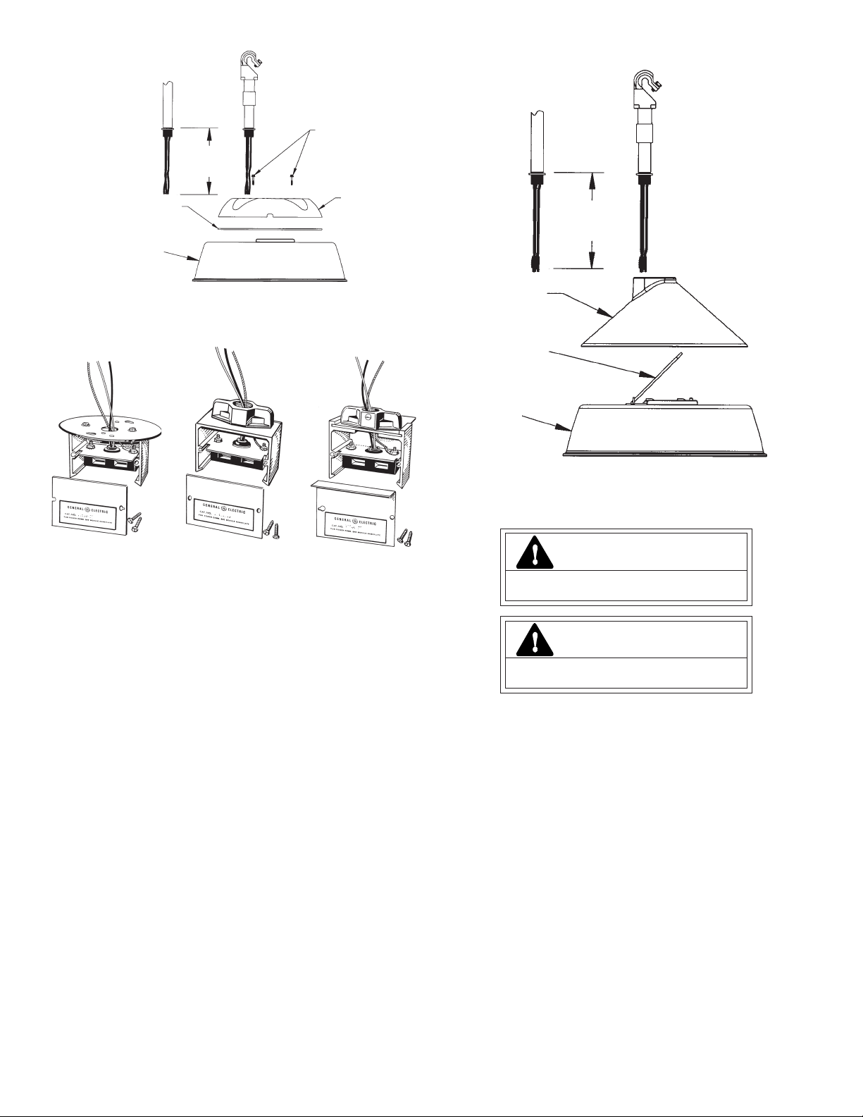
B. Rigid Pendant Mounting
1. Loosen three lens screws and remove refractor and refractor ring from luminaire housing.
2. Loosen reflector screws, remove reflector. Remove nomex wire shield.
3. Thread pendant/conduit into top housing (Figure 4) or mounting hub (Figure 6), and tighten lock
nut.
4. Feed wires through pendant and extend approximately 6 inches of wire into housing and make
necessary connections. (See Wiring section) Connect supply ground lead to the luminaire green
lead.
™
WARNING
Risk of fire
• Keep combustible materials away from lens
– see instructions
• Use lamps specified on nameplate
• Maintain minimum 3’ below luminaire
If unit is multi-volt, see Wiring Section.
Luminaire Mountings
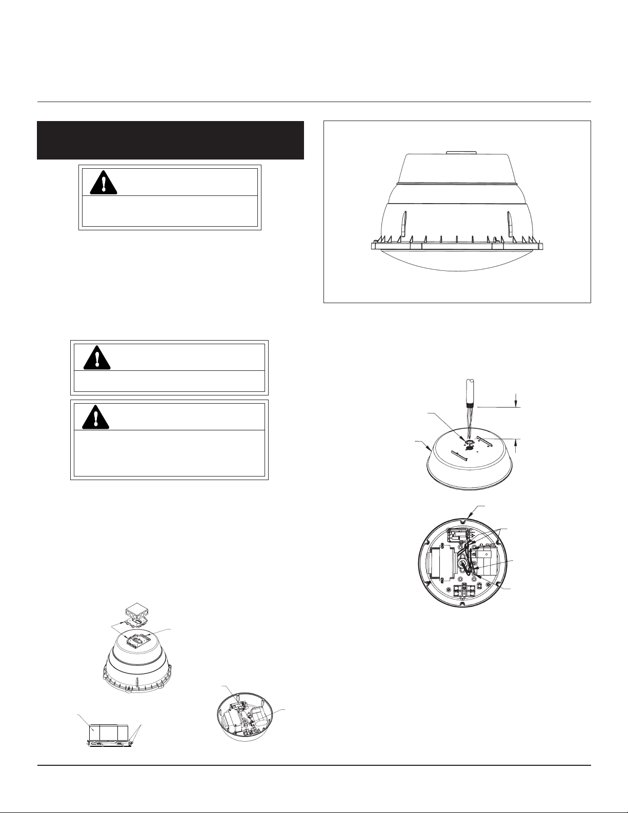
A. Ceiling Mounting
1. Attach mounting plate to electrical junction box and pull incoming power leads through oval hole
in mounting plate.
2. Suspend luminaire below j-box and attach wireform by squeezing legs together slightly and
inserting through rectangular j-box mounting plate holes.
3. With luminaire hanging below j-box make electrical connections and place wires into j-box.
(Figure 1)
4. Swing luminaire into place, mate two mounting plates and slide together until plates lock into
place. (Figure 2)
5. To remove fixture from j-box, luminaire must be opened, by loosening three lens screws, then
loosening reflector screws, and removing reflector. The locking screw must be backed out
approximately one-half inch. (Figure 3)
Mounting
Plates
Figure 1
Junction
Box
Wireform
Locking
Screw
Mounting
Plate
Wire
Clip
Locknut
(By User)
Cover
6 Inches
(152mm)
Figure 4
Cover
Connectors
Wire Clip
Ground Lead
Figure 5
5. Route incoming supply conductors through wire clip (D, Figure 5) provided. Re-attach nomex
shield.
6. Reassemble luminaire.
C. Flexible Pendant Mounting
1. Follow procedure for rigid pendant mounting B1-B6.
2. If adjustment is needed to balance luminaire and have conduit hang vertical, loosen the four
screws in the slotted holes, slide the mounting hub until luminaire hangs straight, re-tighten
screws. Use widest bolt spacing possible to secure hub to cover.
Figure 2
These instructions do not purport to cover all details or variations in equipment nor to provide for every possible contingency to be met in connection with installation, operation or
maintenance. Should further information be desired or should particular problems arise which are not covered sufficiently for the purchaser’s purposes, the matter should be referred
to GE Lighting Solutions.
Figure 3
Page 2
6 Inches
(152 mm)
Screws
Set Screw
Gasket
Figure 6
D. Luminaires with primary disconnects (outlet box hanging hardware Figure 7, rigid pendant
hardware Figure 8 and flexible pendant hanging hardware Figure 9)
1. Remove cover plate(s) and attach hanging hardware to pendant/conduit and tighten set screw.
Cover
Hub
Figure 7 Figure 8 Figure 9
2. Feed supply wire through conduit and into disconnect housing. Make necessary wire connections.
3. Slide the extrusion attached to the luminaire completely into the hanger extrusion. Replace
cover plate.
(Cover plate is necessary to lock luminaire into place on the hardware, cover electrical
connections and, if so equipped, seal unit from water.)
WIRING
Make all electrical connections in accordance with the National Electrical Code and any applicable
local code requirements.
Verify that supply voltage is correct by comparing it to nameplate.
For Rigid Pendant and Flexible Pendant mounting, customer’s supply connections must be above the
Nomex Wire Shield (Reference: B. Rigid Pendant Mounting, Note 2 and 5.)
IF SINGLE VOLTAGE – All single voltage/wattage ballasts are pre-wired such that user need only
connect supply conductors.
IF MULTIVOLT – (120/208/240/277) Units are pre-wired for 277. To change voltage of unit to a voltage
other 277 volts:
Disconnect incoming power lead from 277-volt ballast lead. Insulate the end of the 277-volt
ballast lead. Reconnect incoming power lead to the ballast lead marked with the correct voltage.
Incoming power lead should be stripped back 3/8” and firmly inserted in the plastic termination block
on the desired voltage ballast lead.
10 Inches
(254 mm)
Bird Shield
Wireform
Cover
Figure 10
MAINTENANCE
CAUTION
Risk of burn
• Allow lamp/fixture to cool before handling
WARNING
Risk of burn
• Do not touch operating luminaire
Cleaning
Occasionally it will be necessary for the refractor to be cleaned to maintain appearance and light
levels. The frequency of cleaning will be dependent on the ambient dirt level and minimum light level
required. Refractor and housing should be washed with a solution of warm water and mild household
detergent, rinsed with clean water and wiped dry. Should the interior optical assembly become dirty, clean
the reflector and interior of refractor as described above. Replace gasket if damaged.
Lamp Replacement
Light output of a luminaire is also dependent on the age of the lamp. In applications where light level
is critical it may be desirable to replace lamps before the burn out. Consult lamp manufacturer’s data for
lamp replacement frequency and other safety issues.
Replace blackened lamps immediately.
LAMPS
Use only lamps specified on nameplate. Observe lamp manufacturer’s recommendations and
restrictions on lamp operation, particularly ballast type, burning position, etc.
Lamp Tightness- Mogul Base Lamp: Lamp should be securely inserted to the NEMA-EEI specified
torque of 35 inch-pounds, which is best achieved by very firmly tightening to insure application of sufficient
torque.
Tightening must be sufficient to fully depress and load the center contact of the socket.
Lamp Tightness- Medium Base Lamp: Lamp should be tightened to a light firmness sufficient to
depress the center contact of the socket.
Switched Quartz- Units equipped for switched quartz operation will have the socket installed in the
reflector. Install quartz lamp.
Page 3

GE
g
CONSERVER CES INSTRUCTIONS POUR UTILISATION ULTÉRIEURE
Lighting Solutions
Luminaire de garage avec bande d'éclairage vers le haut
À LIRE ATTENTIVEMENT AVANT L'INSTALLATION
AVERTISSEMENT
Risque de commotion
• Coupez l'alimentation secteur avant toute intervention.
– Reportez-vous aux instructions
GÉNÉRALITÉS
Ce luminaire est conçu pour des applications à montage collé ou pendant au plafond dans un garage,
et doit être monté et entretenu en respectant les recommandations qui suivent.
DÉBALLAGE
Ce luminaire a été correctement emballé de façon à ce qu'aucune de ses parties n'ait été endommagée
durant le transport. Inspectez-le pour confirmation.
Le carton doit contenir un luminaire au complet avec ensemble de montage et ampoule installée dans
sa douille (version à culot moyen seulement).
INSTALLATION
ATTENTION
L'unité peut tomber si elle est mal installée
• Suivez les instructions d'installation
GEH-5971B
INSTRUCTIONS
Garage Guardian
B. Montage suspendu rigide au plafond
1. Desserrez les trois vis de lentille et ôtez le réfracteur et son anneau du carter du luminaire.
2. Desserrez les vis de déflecteur, ôtez le déflecteur. Enlevez l'écran en maille Nomex.
3. Vissez le conduit de suspension dans le haut du carter (Figure 4) ou le moyeu de montage
(Figure 6) et serrez l'écrou de blocage.
4. Passez les fils dans le conduit de suspension et sortez-les d'environ 15 cm dans le carter, puis
réalisez les connexions nécessaires (voir la section sur le câblage). Branchez le fil de terre de
l'arrivée d'alimentation sur le fil vert du luminaire.
™
AVERTISSEMENT
Risque de départ d'incendie
• Gardez les matériaux combustibles à l'écart de la lentille
– Reportez-vous aux instructions
• Utilisez des ampoules spécifiées sur la plaque signalétique
• Maintenez un espace libre d'au moins 90 cm sous le luminaire
Si l'unité est multi tensions, consultez la section sur le câblage.
Montages du luminaire
A. Montage contre le plafond
1. Fixez la plaque de montage au boîtier de raccordement électrique et tirez les fils d'arrivée
d'alimentation par le trou ovale dans la plaque de montage..
2. Suspendez le luminaire sous le boîtier de raccordement et fixez le Wireform en pressant
légèrement les pattes ensemble et en les insérant au travers des trous de plaque de montage
du boîtier de raccordement.
3. Avec le luminaire pendant sous le boîtier de raccordement, réalisez les connexions électriques
et ramenez les fils dans le boîtier (Figure 1).
4. Basculez le luminaire en place, appairez deux plaques de montage et glissez-les ensemble
jusqu'à leur verrouillage en place (Figure 2).
5. Pour enlever le luminaire du boîtier de raccordement, il fait l'ouvrir, en desserrant les vis de
lentille, puis en desserrant les vis de réflecteur, et en ôtant le réflecteur. La vis de blocage doit
être sortie d'environ 1,3 cm (Figure 3).
Plaques de
montage
Figure 1
Boîtier de
raccordement
Wireform
Vis de
blocage
Plaque de
montage
Serre
fils
Écrou de blocage
(par utilisateur)
Couvercle
6 pouces
152 mm
Figure 4
Couvercle
Connecteurs
Serre fils
Fil de terre
Figure 5
5. Faites passer les fils d'arrivée d'alimentation dans le serre fils (D, Figure 5) fourni. Fixez à
nouveau l'écran en Nomex.
6. Remontez le luminaire.
C. Montage suspendu flexible au plafond
1. Suivez la même procédure que pour le montage suspendu rigide (B1 à B6).
2. Si un réglage est nécessaire pour équilibrer le luminaire, et que le conduit pende bien
verticalement, desserrez les quatre vis dans les trous allongés, glissez le moyeu de montage
jusqu'à ce que le luminaire pende droit, et resserrez ces vis. Utilisez l'espacement de boulons
le plus grand possible pour fixer le moyeu sur le couvercle.
Figure 2
Ces instructions n'ont pas pour destination de couvrir tous les détails ou variantes de l'équipement, ni de répondre à toutes les éventualités que vous pourriez rencontrer pendant l'installation,
le fonctionnement ou l'entretien. Si vous souhaitez des informations complémentaires, ou si vous rencontrez un problème particulier qui ne soit pas adressé de votre point de vue d'acheteur,
le sujet doit être remonté jusqu'à la société GE Lighting Solutions
Figure 3
Page 4

6 pouces
(152 mm)
Vis
Set Screw
Joint
Figure 6
D. Luminaires avec accouplement d'alimentation (dispositifs de suspension : sur boîtier électrique
en Figure 7, pendant rigide en Figure 8 et pendant flexible en Figure 9)
1. Enlevez la/les plaque(s) de couverture et fixez le dispositif de conduit de suspension, puis serrez
Couvercle
les vis de fixation.
Moyeu
Figure 7 Figure 8 Figure 9
2. Passez les fils d'alimentation par le conduit dans le boîtier d'accouplement. Réalisez les
connexions.
3. Faites glisser l'extrusion fixée au luminaire complètement dans l'extrusion de la suspension.
Remettez la plaque de couvercle (La plaque de couvercle est nécessaire pour bloquer le
luminaire en place sur le dispositif, recouvrir les connexions électriques, et si c'est la
configuration, isoler l'unité de l'eau).
CÂBLAGE
Réalisez toutes les connexions électriques en conformité avec la norme nationale américaine ou toute
réglementation locale applicable.
Vérifiez que le secteur d'alimentation a la bonne tension indiquée sur la plaque signalétique.
Pour les montages en suspension pendante rigide ou flexible, les connexions d'alimentation du client
doivent arriver au-dessus de l'écran à maille Nomex (Référence : B. Montage suspendu rigide au plafond,
paragraphes 2 et 5).
APPAREIL MONOTENSION – Tous les ballasts de tension/puissance unique sont précâblés, et
l'utilisateur n'a qu'à brancher les fils secteurs d'arrivée.
APPAREIL MULTITENSIONS (120/208/240/277 V) Les unités arrivent par sécurité précâblées pour du
277 V. Pour modifier l'unité si la tension secteur est inférieure :
Débranchez le fil d'arrivée d'alimentation du fil de ballast 277 V dont vous isolerez l'extrémité
nue. Rebranchez le fil d'arrivée d'alimentation sur le fil du ballast marqué à la tension voulue. Le fil
d'arrivée d'alimentation doit être dénudé sur 9 mm et fermement inséré dans le bloc de terminaison
en plastique sur le fil de ballast de tension voulue.
10 pouces
(254 mm)
Écran anti-oiseaux
Wireform
Couvercle
Figure 10
ATTENTION
Risque de brûlure
• Laissez l'ampoule et l'appareil refroidir avant toute
manutention
AVERTISSEMENT
Risque de brûlure
• Ne touchez pas un luminaire allumé
Nettoyage
Il sera de temps en temps nécessaire de nettoyer le réflecteur afin de conserver
l'apparence et le niveau d'éclairage. La fréquence des nettoyages dépendra du niveau de
poussière ambiant et du niveau d'éclairage minimum tolérable. Le réfracteur et le carter
peuvent se laver avec une solution de détergent ménager doux dans de l'eau tiède, avec
rinçage à l'eau claire et essuyage. Si l'ensemble optique intérieur devenait sale, nettoyez
réflecteur et l'intérieur du réfracteur comme décrit plus haut. Remplacez le joint s'il est
endommagé.
Remplacement d'ampoule
Le niveau d'éclairage d'un luminaire est également dépendant de l'âge de son ampoule.
Dans les applications où le niveau lumineux est critique, il peut être judicieux de remplacer
les ampoules avant qu'elles ne soient grillées. Consultez les données du fabricant d'ampoules
pour la fréquence des remplacements et d'autres aspects de sécurité.
AMPOULES
N'utilisez que des modèles d'ampoules spécifiés sur la plaque signalétique. Suivez les recommandations
et les restrictions de fonctionnement de son fabricant, en particulier concernant type de ballast, position
d'allumage, etc.
Serrage d'ampoule – Culot Mogul : L'ampoule doit être bien insérée au couple de serrage spécifié
NEMA-EEI de 35 pied-livres, ce qui s'obtient en serrant très fermement à la main.
Le serrage doit être suffisant pour bien enfoncer et charger le contact central de la douille.
Serrage d'ampoule – Culot moyen : L'ampoule doit être serrée avec une fermeté modérée suffisante
pour enfoncer le contact central de la douille.
Quartz commuté – Les unités équipées pour ce type de fonctionnement auront leur douille installée
dans le déflecteur. Il suffit d'y installer une ampoule à quartz.
GE Lighting Solutions • 1-888-MY-GE-LED • www.gelightingsolutions.com
16943533----888
GE Lighting Solutions is a subsidiary of the General Electric Company. Evolve and other trademarks belong to GE Lighting Solutions. The GE brand and logo are trademarks of the General Electric Company.
© 2011 GE Lighting Solutions. Information provided is subject to change without notice. All values are design or typical values when measured under laboratory conditions.
g
Remplacez immédiatement les ampoules grillées ou noircies.
35-201578-163 (3/08)
 Loading...