

GE CGP650SET2SS, CGP650SET3SS, CGP650SET4SS, PGP976DET2BB, PGP976DET2WW Installation Guide
...Page 1
I stollotio
36" SealedGasCooktop
I structio s
j r_l Questions? call 800.GE.CARES (800.432.2737) or Visit our Website at: GEAppliances.com
IN THE COMMONWEALTH OF
MASSACH USETTS:
, This product must be installed by a licensed
plumber or gas fitter.
, When using ball-type gas shut-off valves, they
shall be the T-handle type.
, A flexible gas connector, when used, must not
exceed 3 feet.
BEFORE YOU BEGIN
Read these instructions completely
and carefully.
.IMPORTANT - Savetheseinstructions
for local inspector's use.
, IMPORTANT - ObserveaUgoverning
codes and ordinances.
, Note to Installer- Be sure to leave these
instructions with the Consumer.
Note to Consumer - Keep these instructions for
future reference.
, Product failure due to improper installation is not
covered under the Warranty.
,AWARNING - This appliancemust be
properly grounded.
In Canada, call 1.800.561.3344 or Visit our Website at: www.geappliances.ca
PGP976, PGP986, CGP650
FOR YOUR SAFETY:
_I,WARNING - iftheinformationinthis
manual is not followed exactly, mfire, explosion
or gas leak may result causing property damage,
personal injury or death.
Do not store or use gasoline or other flammable
vapors and liquids in the vicinity of this or any
other appliance!
Do not install this product with an air curtain
hood or other range hood that operates by
blowing air down on the cooktop. This airflow
may interfere with operation of the gas burners
resulting in fire or explosion hazard.
WHAT TO DO IF YOU SMELL
GAS:
, Do not try to light any appliance. Do not touch
any electrical switch; do not use any phone in
your building.
immediately coil your gas supplier from a
neighbor's phone. Follow the gas supplier's
instructions.
, If you cannot reach your gas supplier, coil the
fire deportment.
installation and service must be performed by
a qualified installer, service agency or the gas
supplier.
i
. IMPORTANT - Leak testingofthe
applianceshallbe conducted accordingto the
manufacturer's instructions.
, Proper installation is the responsibility of the
installer and product failure due to improper
installation is NOT covered under warranty.
WARN ING - Disconnectallelectrical
power at the main circuit breaker
or fuse box before installing.
31-i0955 ii-13 GE i
This cooktop has been certified by UL. You'll find
safety precautions in your Owner's Manual. Read
them carefully.
Installation of this cooktop must conform with
local codes or in the absence of local codes with
the National Fuel Gas Code, ANSI Z223.Z/NFPA
54-Latest edition.
Be sure your cooktop is installed properly by a
qualified installer or service technician.
To eliminate reaching over surface burners,
cabinet storage above burner should be avoided.
Do not install the unit near an outside door or
where a draft may affect its use.
Page 2

Installation Instructions
IMPORTANT SAFETY INSTRUCTIONS
ELECTRICAL REQUIREMENTS
This appliance must be supplied with the proper
voltage and frequency and connected to an
individual, properly grounded branch circuit,
protected by a circuit breaker or fuse having
amperage as noted on the rating plate.
We recommend you have the electrical wiring and
hookup of your cooktop connected by a qualified
electrician. After installation, have the electrician
show you where your main cooktop disconnect is
located.
Check with your local utilities for electrical codes
which apply in your area. Failure to wire your
cooktop according to governing codes could result
in a hazardous condition.
If there are no codes, your cooktop must be wired
and fused to meet the requirements
of the National Electrical Code, ANSI/NFPA No. 70--
Latest edition. You can get a copy
by writing:
National Fire Protection Association
Batterymarch Park
Quincy, P1A 02269
PARTS INCLUDED
2Screws Regulator
MATERIALS YOU MAY NEED
Joint Sealant Pipe Fittings
CSA-Approved Flexible Gas Line
3/8" Min. ID, 1/2" NPTConnection,
3-foot Maximum Length (Massachusetts Only)
2 Hold
Down Brackets
Shut-Off Valve
In Canada your cooktop must be wired and fused
to meet the requirements of the Canadian Electrical
Code.
Be sure the installation of this product in a mobile
home conforms with the Manufactured Home
Construction and Safety Standard, Title 24 CFR,
Part 3280. If this standard does not apply, you
must follow the standard for Manufactured Home
Installations, ANSI/NCSBS A225.1 or with local
codes where applicable.
You can get a copy of the Federal Standard by
Writing:
Office of Mobile Home Standards
HUD Building
451 7th Street, S.W.
Washington, D.C. 24010
TOOLS YOU WILL NEED
FOR INSTALLATION
Pencil
Saber Saw
Phillips-Head
Screwdriver
Pipe Wrench
Ruler or Straightedge
!/8" Drill Bit & Electric or
Hand Drill
Safety Glasses
Page 3

Installation Instructions
PRE-INSTALLATION CHECKLIST
When preparing cooktop opening, make
[Z]
sure the inside of the cabinet and the
cooktop do not interfere with each other.
(See section on preparing the opening.)
Remove packaging materials, grote boxes,
@
regulator with literature, and literature
package from the cooktop before beginning
installation.
i/
/i/
Foam
Pac_,_,_///_,_r,_/,_ _ _ _ _
Cooktop J
Package
Grate boxes
Remove Installation Instructions from
E1
literature pack and read them carefully
before you begin.
Be sure to place all literature (Owners Manual,
Installation Instructions, etc.)in a safe place
for future reference.
Make sure you have all the tools and
El
materials you need before starting the
installation of the cooktop.
Your home must provide the adequate
El
electrical service needed to safely and
properly use your cooktop. (Refer to section
on electrical requirements.)
When installing your cooktop in your home,
FF1
make sure all local codes and ordinances
are followed exactly as stated.
Make sure the wall coverings, countertop
[]
and cabinets around the cooktop can
withstand heat (up to 200°F) generated by
the cooktop.
Page 4

Installation Instructions
PREPARING THE OPENING
MAINTAIN THE FOLLOWING
MINIMUM CLEARANCE DIMENSIONS
23" MAX. De R - IVllN. clearance
of unprotected from cutout to right
overhead side wall
cabinets
I
]0" MIN. clearance from
countertop to unprotected
overhead surface
C- MIN. I
clearance from I
cutout to rear
wall
L - MIN. clearance
from cooktop to left
side wall ]0" or wider
2-1/2" MIN from cutout to
front of countertop
ALL HORIZONTAL
CLEARANCES MUST
BE MAINTAINED FOR PGP976
A MINIMUM OF 18" PGP986
ABOVETHECOOKING CGP650
SURFACE,
NOTE: Allow 7/16" minimum
vertical clearance from s 11/16 €
the cooktop bottom (or 3_
3-11/16" minimum depth
from the countertop) to any
combustible surfaces, such as
a cabinet drawer.
cabinetbase
L
3-3/a,"
12"
12"
_ ,-2"
6" 3-3/8"
12" 3-3/8"
12" 3-3/8"
DRAWERI_
18" MIN. height
countertop
to nearest
cabinet on either
side of unit
R C
7/16"
RECOMMENDED GAS SUPPLY
LOCATION FROM BACKWALL
1" Min. From Backwall
Recommended
gas supply
location
From Cutout
Center Line
r_ MAKE SUREWALL COVERINGS,
COUNTERTOP AND CABINETS
AROUND COOKTOP CAN WITHSTAND
HEAT (UPTO 200°FI GENERATED BY
COOKTOP
countertop must l
withstand heat I
For island installation, maintain
2-1/2 in. minimum from cutout to
front and back edge of countertop. Maintain 3 in.
minimum from cutout to side edges of countertop.
E_ OVERALL COOKTOP DIMENSIONS
3-1/4"
18-7/8" _
F_ CUTOUT DIMENSIONS OF COUNTERTOP
To ensure accuracy, it is best to make a template
when cutting the opening in the counter,
19-1/8" width cut
[]_] FOR AMERICANS WITH DISABILITIES
ACT (ADA} FORWARD APPROACH
INSTALLATION ON LY:
Allow 5" minimum I
depth between the I
countertop and an I
enclosure. _
NOTE: The enclosure must be made of wood
material. Also, an access panel is required for the
electrical outlet, pressure regulator, shut-off valve,
hold-down brackets, and service.
I
I
I
I
U
Page 5

Installation Instructions
iNSTALLiNG THE COOKTOP UNiT
LOCATE ELECTRICAL OUTLET AND
rT]
GAS SHUT-OFF VALVE BENEATH
CABINET
NEVER REUSE OLD
CONNECTORS WHEN
INSTALLING THIS
UNIT.
ShutOff _,H IF''
_Valve --_ j ElectricalOutlet 12"
I_ 7f
_1 LJ
II
i
Below
Countertop
ATTACH BRACKETS TO COOKTOP
Remove the screw from the side of the cooktop
and screw the hold-down bracket to the side of the
cooktop unit. Repeat for opposite side of cooktop.
Pre-drilled
Bottom of hole
Cooktop
\
Install a manual shut-off valve in the gas line in an
easily accessible location outside the cooktop. Be
sure you know how and where to shut off the gas
supply to the cooktop. Install the electrical outlet
12" below the countertop.
[_] PROTECT SURFACE OF COOKTOP
Place a towel or tablecloth onto the countertop.
Lay the cooktop upside down onto the protected
surface.
Bottom of cooktop j
Cloth under Cooktop
r_ LOCATE MOUNTING PARTS
Remove the hold down brackets from the literature
package.
Cookto
Surface
r_ INSERT COOKTOP INTO CUTOUT
Insert the cooktop centered into the cutout opening.
Hake sure the front edge of the countertop is
parallel to the cooktop. Hake final check that all
required clearances are met.
Once the unit is in place, screw the
hold- down bracket into the cabinet sides
to secure the unit into place.
Page 6
Installation Instructions
INSTALLATION--GAS CONNECTIONS
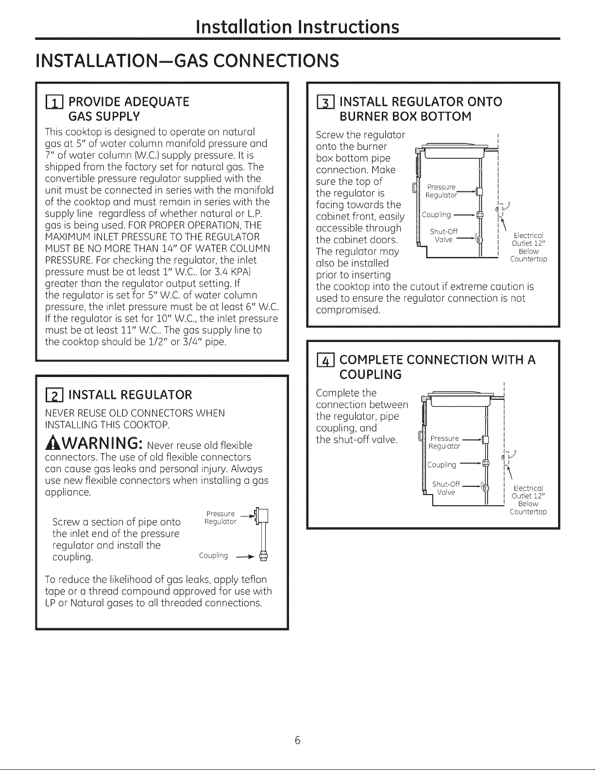
r_ PROVIDE ADEQUATE
GAS SUPPLY
This cooktop is designed to operate on natural
gas at 5" of water column manifold pressure and
7" of water column (W.C.)supply pressure. It is
shipped from the factory set for natural gas. The
convertible pressure regulator supplied with the
unit must be connected in series with the manifold
of the cooktop and must remain in series with the
supply line regardless of whether natural or L.P.
gas is being used. FOR PROPEROPERATION, THE
MAXIMUM INLET PRESSURETO THE REGULATOR
MUST BE NO MORE THAN 14" OF WATER COLUMN
PRESSURE.For checking the regulator, the inlet
pressure must be at least 1" W.C.. (or 3.4 KPA)
greater than the regulator output setting. If
the regulator is set for 5" W.C. of water column
pressure, the inlet pressure must be at least 6" W.C.
If the regulator is set for 10" W.C., the inlet pressure
must be at least 11" W.C.. The gas supply line to
the cooktop should be 1/2" or 3/4" pipe.
_] INSTALL REGULATOR
NEVER REUSEOLD CONNECTORS WHEN
INSTALLING THIS COOKTOP.
, WARNING: Never reuse old flexible
connectors.The use of oldflexibleconnectors
can cause gas leaksand personalinjury.Always
use new flexibleconnectorswhen installinga gas
appliance.
Screw a section of pipe onto
the inlet end of the pressure
regulator and install the
coupling.
Pressure __-]
Regulator 'U]]J
Coupling _
r_ INSTALL REGULATOR ONTO
BURNER BOX BOTTOM
Screw the regulator
onto the burner
box bottom pipe
connection. Make
sure the top of
the regulator is
Pressure 41
Regulotor-----_l
facing towards the
cabinet front, easily
accessible through
the cabinet doors.
The regulator may
also be installed
Coupling l
LI
', Electrical
II Outlet 12"
I Below
Countertop
prior to inserting
the cooktop into the cutout if extreme caution is
used to ensure the regulator connection is not
compromised.
COMPLETE CONNECTION WITH A
COUPLING
Complete the
connection between
the regulator, pipe
coupling, and
the shut-off valve.
Pressure
Regulator
Coupling
Shut-Off _1
Valve
I
II
II Electrical
I Outlet 12"
I Below
Countertop
To reduce the likelihood of gas leaks, apply teflon
tape or a thread compound approved for use with
LP or Natural gases to all threaded connections.
Page 7
Installation Instructions
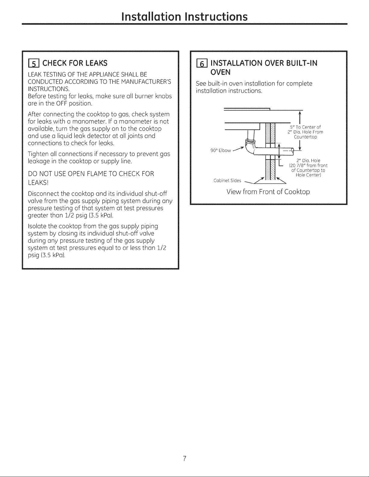
CHECK FOR LEAKS
LEAKTESTING OF THE APPLIANCE SHALL BE
CONDUCTED ACCORDING TO THE MANUFACTURER'S
INSTRUCTIONS.
Before testing for leaks, make sure all burner knobs
are in the OFF position.
After connecting the cooktop to gas, check system
for leaks with a manometer. If a manometer is not
available, turn the gas supply on to the cooktop
and use a liquid leak detector at all joints and
connections to check for leaks.
Tighten all connections if necessary to prevent gas
leakage in the cooktop or supply line.
DO NOT USE OPEN FLAME TO CHECK FOR
LEAKS!
Disconnect the cooktop and its individual shut-off
valve from the gas supply piping system during any
pressure testing of that system at test pressures
greater than 1/2 psig (3.5 kPa).
Isolate the cooktop from the gas supply piping
system by closing its individual shut-off valve
during any pressure testing of the gas supply
system at test pressures equal to or less than 1/2
psig (3.5 kPa).
[_] INSTALLATION OVER BUILT-IN
OVEN
See built-in oven installation for complete
installation instructions.
1
5" To Center of
2" Dia. Hole From
Countertop
90 ° Elbow
2" Dia. Hole
(20 7/8" from front
of Countertop to
Hole Center)
Cabinet Sides __ .J_"
View from Front of Cooktop
Page 8

Instelletion Instructions
INSTALLATION--ELECTRICAL CONNECTIONS
, WARNING - Disconnect all electrical
power at the main circuit breaker or fuse box
before installing.
ELECTRICAL SUPPLY AND OUTLET
An adequate electrical supply and outlet must
be used to operate the electrical parts of your
cooktop.
[]
The power cord of this appliance is equipped
with a 3-prong (grounding) plug which must
be used with a properly grounded 3-hole
outlet with a standard 120 Volt, 60 cycle AC
household current.
D
If you do not have a 3-hole grounded outlet,
have a qualified electrician change your old
one. DO NOT, UNDER ANY CIRCUMSTANCES,
CUT OR REMOVE THE THIRD (GROUND) PRONG
FROM THE POWER CORD. DO NOT USE AN
ADAPTER. DO NOT USE AN EXTENSION CORD.
Insure proper
L ground and
firm connection
before use
Page 9

Installation Instructions
COOKTOP BURNERS
ASSEMBLING THE COOKTOP BURNERS
The electrode of the igniter is exposed. Be careful not to turn on any cooktop controls
while the top of the burner is removed. Do not remove the top or touch the electrode
of any burner while another burner is turned on. Electrical shock might result.
[] Place the burner head onto the burner base. Hake sure to place the correct
burner head on the correct burner base and that the burner head sits level on
the burner base. The burner heads are not interchangeable. Ensure the slot in
the burner head is positioned over the electrode and that the burner head is
fully inserted inside the burner base. A small gap between the base and head is
normal.
Place the burner caps on the burner heads, making sure to place the correct
[]
burner cap on the correct burner head. The burner caps are not
interchangeable. Each cap has three to four pins. Hake sure that the burner
caps are properly seated on the burner heads and that none of the pins sit in the stability chamber.
OR
chamber -_
Burner
base base
Electrode
{\ '7 Burner
Burner cap properly seated
Burner cap not properly seated
J
[_ CHECK IGNITERS
Operation of the electric igniters should be checked after the cooktop and supply line have been carefully
checked for leaks and the cooktop has been connected to the electrical power.
On models so equipped, check to be sure the cooktop is in the UNLOCKED position.
r_ Push and turn a burner valve to the LITE position. All spark igniters will make a series of sparks (ticking
sounds), but only the burner turned to LITE will light.
. The burner should light when gas is available to the burner.
. Once the burner lights, it should be turned out of the LITE position.
r_ Try each valve separately until all burners have been checked.
Page 10

Installation Instructions
T
COOKTOP BURNERS ICONT.}
ITI BURNER IGNITION
Cooktop Spark Ignition-When you turn
the cooktop knob to LITE,the spark igniter makes a
series of electric sparks (ticking sounds) which light
the burner. During a power failure, the burners will
not light automatically. In an emergency, a cooktop
burner may be lit with a match by following the
steps below.
On models so equipped, check to be sure the
cooktop is in the UNLOCKED position.
r_ Light a match and hold the flame near the
burner you want to light. Wooden matches
work best.
r_ Push in and turn the control knob slowly. Be
sure you are turning the correct knob for the
burner you are lighting.
NOTE: If the burner does not light within five seconds,
turn the knob off and wait one minute before trying
again.
[_] BURNER GRATES
The three cooktop grates are designed for specific
positions. For maximum stability, these grates
should only be used in their proper position with
the edges positioned on top of the black bumpers
as shown
/
/
/
/
Grote
//
/'
//'
/'
/
/
//
/
/
Block Grote
Bumpers
[_ THE BURNER FLAMES
Turn each burner on. Flames should be blue in color
with no trace of yellow. The burner flames should
not flutter or blow away from the burner. The flame
should be no less than 1/4" on the lowest setting
and no greater than 1-1/2" on highest setting.
_CAUTION: Ifyouattempt to measure the
flame, please use caution. Burns could result.
i/4" to
i-i/2"
Burners should be checked frequently
Cooktop Burner
10
Page 11

Installation Instructions
OPERATION CHECKLIST
rA1 Make sure all controls are left in the OFF r_
position. Check to be sure the cooktop is in the
UNLOCKED position (on models so equipped).
Make sure the flow of air to and from the
cooktop is unobstructed.
The serial plate for your cooktop is located on
the bottom of the burner box. In addition to the
model and serial numbers, it tells you the ratings
of the burners and the type of fuel and pressure
the cooktop was adjusted for when it left the
factory.
B]
When ordering parts, always include the serial
number, model number and a code letter to
ensure proper replacement parts.
Recheck Steps:
Double check to make sure everything in this
guide has been completed. Rechecking steps
will ensure safe use of the cooktop.
11
Page 12

Installation Instructions
MAKING THE LP CONVERSION
rT1 SAFETY INFORMATION YOU
SHOULD KNOW
The pressure regulator and burner orifices are set
for natural gas. To use LP gas, the regulator and
burner orifices must be converted. The LP orifice
spuds for the cooktop burners are attached to
the regulator along with separate LP conversion
instructions.
JI&L.,/'_LI/IUi_: The cooktop, as shipped from
the factory, is set for use with natural gas. If you
wish to use your cooktop with LPgas, you must
first replace the orifices and convert the pressure
regulator.
_I_W/_KI_I I i_1_: This conversion must be
performed by a qualified installer or gas supplier in
accordance with the manufacturer's instructions
and all codes and requirements of the authority
having jurisdiction. Failure to follow instructions
could result in serious injury or property damage.
The qualified agency performing this work assumes
responsibility for the conversion.
JlLL,,/'_L,!/IU|'_I: The following adjustments
must be made before turning on the burner. Failure
to do so could result in serious injury. Be sure
pressure regulator has been converted as
described in Step 2.
TOOLS YOU WILL NEED
FOR LP CONVERSION
7mm Nutdriver
Safety Glosses
Small Flat-Head
Screwdriver (4mm or
5/]2" tip size,60mm
or 2-]/8" long)
ADJUST YOUR COOKTOP FOR USE
[2]
WITH LP GAS
Disconnect allelectrical power, at the main
circuit breaker or fuse box.
B]
Shut off the gas supply to the cooktop
by closing the manual shut-off valve.
Adjust the pressure regulator, by the following
Fa
instructions:
* Unscrew the cap.
* Carefully look at the spring retainer to locate
the NAT or LP position.
12
Cap Gasket_
N_
NAT.
Position
Pressure Regulator
. Turn the spring retainer over by rotating it
90 deg., pull it from the cap, turn the spring
retainer over so that LP is showing, insert it
back into the cap, and then rotate it 90 deg.
into position.
. Screw the cap back onto the regulator and
tighten.
LP L.P./Propone
Position
Page 13

Installation Instructions
MAKING THE LP CONVERSION (CONT.}
[_ CHANGE COOKTOP BURNER
ORIFICES
FA1 Remove the grates, burner caps, and burner
heads.
[] Using a 7mm nut driver, remove the burner
orifices. These may be accessed through the
burner holes in the cooktop.
Inner j_,(_
burner cap
Burner ,S_ Outer
base -"-__' _ burner
Electrode
Orifice spuds located _l/
through these openings
Tri-Ring Burner
cap
Burner
NOTE: On all burners, the
orifices have a spring-loaded
Retainer
Ring
retaining ring around the hex
head to hold the orifice in the
nut driver during installation
and removal. A slight amount
of force is required to push the
nut driver down over the ring.
OR
BurNer
base
Orifice spud located Electrode
through this opening
Burner
Burner
head
cap
r_ CHANGE COOKTOP BURNER
ORIFICES (CONT.)
PGP976
CGP650 &
PGP986 Simmer: 5! L
Main:58L(x])
Fcl Locate the LPorifices attached to the regulator
along with separate LPconversion instructions.
They will have a digit for size and a letter for type
of gas, on the top or side. (Important: Save the
orifices removed from the appliance for future
use.)
Each orifice will show a series of engraved
marks, (I,II, III, IV or V), located on the top.
These marks denote the location of each orifice to the
cooktop burner.
For PGP976 Models
For PGP986 & CGP650Models
(Shorter)
CENTER BURNER
17,000 BTU/hr Extra Large Burner (PGP976 Models)
Cap
Burner
Set Screw
I
ql_ Choke
I
Extended spud for center
extra large burner
I
Burner
Head
Spud
Extended
Base
Orifice spud located
through this opening
13
Page 14
Installation Instructions
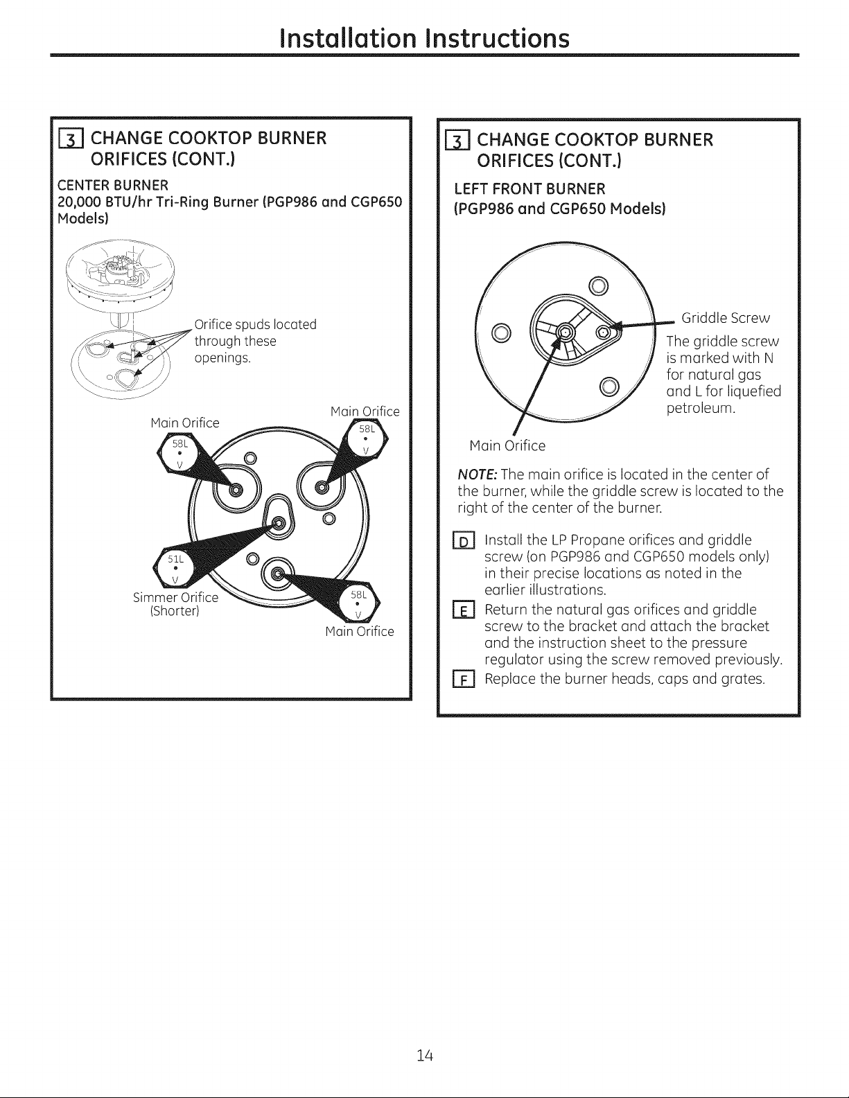
[T_ CHANGE COOKTOP BURNER
ORIFICES (CONT.)
CENTER BURNER
20,000 BTU/hr Tri-Ring Burner (PGP986 and CGP6SO
Models)
spuds located
through these
openings.
Main Orifice
Main Orifice
Simmer Orifice
(Shorter)
Main Orifice
_] CHANGE COOKTOP BURNER
ORIFICES (CONT.)
LEFT FRONT BURNER
(PGP986 and CGP650 Models)
Griddle Screw
The griddle screw
is marked with N
for natural gas
and Lfor liquefied
petroleum.
Main Orifice
NOTE: The main orifice is located in the center of
the burner, while the griddle screw is located to the
right of the center of the burner.
r6] Install the LPPropane orifices and griddle
screw (on PGP986and CGP6S0models only)
in their precise locations as noted in the
earlier illustrations.
r_ Return the natural gas orifices and griddle
screw to the bracket and attach the bracket
and the instruction sheet to the pressure
regulator using the screw removed previously.
r_ Replace the burner heads, caps and grates.
14
Page 15

Installation Instructions
MAKING THE LP CONVERSION (CONT.}
ADJUST BURNER FLAMES
Turn all burners full on and check the flames.
They should be blue in color with some yellow
tipping at the ends of the flame. Foreign
particles in the gas line may cause an orange
flame at first, but this will soon disappear.
r_ Turn the cooktop burner knob to the lowest
setting while observing the flame.
Adjust the low flame setting using the valve bypass
screw as follows:
Low-setting adjustments must be made with two
other burners in operation on a medium setting.
This prevents the low flame from being set too low,
resulting in the flame being extinguished when
other burners are turned on.
E1 To adjust the flame,
remove the knobs. Use
screwdriver to remove
valve stem plugs as
shown.
Insert a screwdriver
through the access hole
in valve switch. Engage
adjustment screw in
valve. Refer to the
illustration below that
matches the adjustment
screw location for
your model. The
griddle burner (PGP986
and CGP650) has 2
adjustment screws,
one for the left rear
burner and one for the
left front burner during
griddle control. Griddle
control must be turned
to LO when making this
adjustment.
, If the flames were too
small or fluttered, open
the valve more than the original setting.
Left of stem
For left front griddle
burner and tri-ring
burner simmer
adjustment screw
Inside ste m_'_._¢_
For all burners
except tri-ring
r_ Testing Flame Stability:
Test 1 - Temporarily replace knobs. Turn the
knob from "HI" to the lowest setting
quickly. If the flame goes out at the
lowest setting, increase the flame size
and test again.
Test 2 -
El Flame Recheck:
After the adjustment is made, turn all burners off.
Ignite each burner individually. Observe the flame
at the "HI" position. Rotate the valve to the lowest
setting and be sure that the flame size decreases
as the valve is rotated counterclockwise.
TO CONVERT THE COOKTOP BACK TO NATURAL
GAS, REVERSETHE STEPS UNDER HAKING THE LP
CONVERSION.
Once the conversion is complete and checked ok,
replace valve stem plugs and knobs, and fill out
the LP sticker. Include your name, organization and
date conversion was made. Apply the sticker near
the cooktop gas inlet opening to alert others in
the future that this appliance has been converted
to LP gas. If converting back to natural gas from
LP, please remove the sticker so others know the
appliance is set to use natural gas.
With the burner on the lowest setting,
open and close the cabinet door
under the cooktop. If the flame is
extinguished by the air currents
created by the door movement,
increase the flame height and test
again.
, If the flames blew away from the burner,
close the valve more than the original
setting.
B] Hake the adjustment by slowly turning the
screw until flame appearance is correct.
15
Page 16

Notes.
16
Page 17

I structio s
Ta lede cuisson scell
d'i stallati
Web 8 I'adresse : www.electromenagersge.ca
au gaz de 91.4 cm (36")
AVANT DE COMMENCER
Avant de commencer, lisez attentivement la totalit#
de ces instructions.
.IMPORTANT - Conservezces
instructions pour votre inspecteur local.
, IMPORTANT - Respectez toutesles
ordonnances et les codes Iocaux.
, Note 6 I'installateur - Assurez-vous de laissez ces
instructions au consommateur.
, Note au consommateur - Conservez ces
instructions pour r6f6rence future.
, La garantie ne couvre aucune panne due
a une mauvaise installation.
AAVERTISSEMENT -
Cet appareil doit @trebien mis 6 la terre.
PGP976, PGP986, CGP650
POUR VOTRE SI_CURITI_
A AVERTISSEMENT -
Si vous ne suivez pas exactement les instructions
de ce manuel, vous risquez d'occasionner un
incendie, une explosion ou une fuite de gaz, qui
peuvent provoquer des dommages mat#riels, des
blessures corporelles ou la mort.
Ne conservez pas ou n'utilisezjamais d'essence
ou d'autres liquides ou vapeurs inflammables 6
proximit# de cet appareil ou de tout autre appareil
m#naged
Ne pas installer ce produit si I'on utiJise une hotte
6 rideau d'air ou une hotte de cuisini_re soufflant
I'air au-dessus de la surface de cuisson. Le d_bit
d'air peut nuire au fonctionnement des br@leurs
6 gaz et repr_sente un risque d'incendie ou
d'explosion.
.IMPORTANT - vousdevez
v#rifierque cetappareiln'oitpas de fuite
conform#ment aux instructionsdu fabricant.
, L'installateur est responsable d'une bonne
installation et la garantie ne couvre aucune
panne due 6 une mauvaise installation.
A AVERTISSEMENT - D6brancheztout
courant #lectrique au niveau du disjoncteur de la
maison ou de la boTte 6 fusibles avant d'installer.
CI QUE VOUS DEVEZ FAIRE Sl
VOUS SENTEZ LE GAZ"
, N'essayezjamais d'allumer un appareil
#lectrom6nager. Netouchez 6 aucun
commutateur d'61ectricit6, n'utilisez jamais un
t616phonedans votre batiment.
, Appelez imm6diatement votre fournisseur de
gaz 6 I'aide du t616phoned'un voisin. Suivezles
instructions de votre fournisseur de gaz.
, Sivous ne pouvez pas entrer en contact avec
votre fournisseur de gaz, appelez les pompiers.
L'installation et le service de votre table de cuisson
doivent _tre faits par un installateur qualifi6, un
technicien de service ou votre fournisseur de gaz.
31-i0955 ii-13 GE i
Page 18

Instructions d'installation
INSTRUCTIONS IMPORTANTES DE SI CURITI
Cette table de cuisson a 6t6 homologu6e UL. Vous
trouverez des pr6cautions 6 prendre en mati6re de
s6curit6 dans votre Guide d'utilisation et de soins.
Lisez-les attentivement.
. L'installation de votre table de cuisson
dolt se conformer aux codes Iocaux ou, en
I'absence de codes Iocaux, au National Fuel Gas
Code, ANSI Z223.1/NFPA 54 Derni6re 6dition.
. Assurez-vous que votre table de cuisson soit
bien install6e par un installateur qualifi6 ou un
technicien de service.
, Pour 61iminer tout mouvement corporel
au dessus des brOleurs de votre table de cuisson,
6vitez de placer des armoires de cuisine au
dessus des br01eurs.
. N'installezjamais votre appareil pr6s d'une porte
d'entr6e ou dans un emplacement oO un courant
d'air peut g6ner son usage.
s s
BESOINS D'ELECTRICITE
PII_CES COMPRISES
2vis R_gulateur 2 Supports de fixation
MATI'RIAUX DONT VOUS POUVEZ
AVOIR BESOIN
Agent de scellement
de tuyau
Raccord flexible de gaz approuv6 par I'ACNOR
Raccords de tuyau×
DI min 3/8", Jonction NPT1/2
Robinet d'alimentation
de gaz
Cet appareil m6nager dolt 6tre Iivr6 avec le bon
voltage et la bonne fr6quence et branch6 6 son
propre circuit de d6rivation bien mis 6 la terre,
prot6g6 par un disjoncteur ou un fusible qui ont
I'amp6rage not6 sur la plaque min6ralogique de
votre appareil.
Nous vous recommandons de faire brancher le
cSblage 61ectrique et la fiche de votre cuisini6re
par un 61ectricien qualifi6. Apr6s I'installation,
demandez 6 1'61ectricien de vous montrer
I'emplacement de votre coupe-circuit principal.
Demandez 6 votre entreprise de services publics les
codes 61ectriques en vigueur dons votre r6gion. En
ne c_blant pas votre cuisini6re conform6ment aux
codes en vigueur, vous provoquez une situation
dangereuse. En I'absence de codes, vous devez
c_bler et isoler votre cuisini6re conform6ment aux
exigences du Canadian Electrical Code.
OUTILS DONT VOUS AUREZ BESOINS
Crayon
Scie sauteuse
Tournevis Phillips
R_gle ordinaire ou de
v@ification
Lunettes de s_curit_
CI66 tuyau
Perceuse 6 main ou _lectrique
et foret de !/8po
Page 19

Instructions d'installation
LISTE DE VITRIFICATION AVANT INSTALLATION
Pour pr6parer I'ouverture de la surface de
[]
cuisson, vous devez vous assurer que
I'int6rieur de I'armoire ne touche pas la table
de cuisson {consultez la section sur la
pr6paration de I'ouverture).
Enlevez les mat6riau× d'emballage, les
@
boTtes de grille, le r6gulateur avec sa
documentation et la documentation de
votre table de cuisson avant de commencer
6 I'installer.
Documentotion
Bottes de
grille
/
Enlevez les instructions d'installation de la
D
trousse de documentation et lisez-les
soigneusement avant de commencer.
Assurez-vous de bien ranger toute la
documentation,(Hanuel du propri6taire,
Instructions d'installation, etc.) dans un
endroit sOr pour r6f6rence future.
Assurez-vous d'avoir tousles outils et tous
r67
les mat6rau× n6cessaires avant de
commencer 6 installer votre table de
cuisson.
rE7 Votre maison dolt @tre aliment6e en courant
61ectrique ad6quat pour vous permettre de
bien utiliser en toute s6curit6 votre table de
cuisson. (Consultez la section sur les besoins
d'61ectricit6.)
cuisson
r_ pour installer votre table de cuisson dans
votre maison, assurez-vous de vous
conformer scrupuleusement 6 tous les
codes et 6 toutes les ordonnances locales.
Assurez-vous que les rev6tements de mur, le
[]
comptoir et les armoires autour de la table
de cuisson puissent supporter la chaleur
[pouvant atteindre 93°C {200°F)] produite
par la table de cuisson.
Page 20

Instructions d'installation
PREPARATION DE L'OUVERTURE
r_ vous DEVEZ RESPECTERLES
DEGAGEMENTS MINIMAU× SUIVANT
Profondeur max de 55 R- MIN.
cm (15") des armoires
en surplomb D6gagement
I droit
D#gagement min. de 76 cm
(30") du comptoir 6 la surface Hauteur min
en non surplomb non prot6g#es 45 cm (18")
C - MIN. du comptoir
D6gagement 6 I'armoire la
entre I'ouverture plus proche
et ]emur arri_re de chaque
L - MIN. D#gagement
entre la d6coupe et le
mur lot@a] gauche
2-1/2" MIN. Entre I'ouverture
et le devant du eomptoir
L
PGP976 9,5 cm(3-5/4")
PGP986
CGP650
TOUS LES D#GAGEMENTS HORIZONTAUX DOIVENT
S'APPLIQUER SUR UNE DISTANCE MINiMALE DE 45,7 CM
(18") AU-DESSUS DE LA SURFACE DE CUISSON.
30,5 cm (12") 30,5 cm (12") 8,6cm(3-3/8")
30,5 cm (12") 30,5 cm (12") 8,6cm(3-3/8")
Base d'armoire
de 76,2 cm (30")
ou sup@ieur
R C
15,2 cm (6") 8,6cm(3-3/8")
REMARQUE :Laissez un 9,4cm ]
d6gagement vertical minimum (3-11/1B")(
de 1,1cm (7/16 po) entre le
dessus de la table de cuisson
(ou une profondeur minimum
de 9,4 cm (3 11/16 po) et route
surface combustible, par
exemple un tiroir d'armoire.
Pour une installation en Tlot, maintenir
une distance minimum de 6,3 cm (2 !4 po)
entre le bord et le dos du comptoir. Garder un espace de
7,6 cm (3 po) minimum sur Ins c6t@sdu comptoir,
entre I'ouverture
et ]e mur Iot@al
:6t6 de
I'appareil
1,1 cm (7/16")
[_ EMPLACEMENT RECOMMANDE DE
L'ALIMENTATION DE G.AZ
PARTIR DU MUR ARRIERE
2.5 cm (i")min. du mur artiste
Emplacement
recommand6 de
I'aJimentation
de gaz
[_] ASSUREZ-VOUS QUE LES
REVETEMENTS MUR, LE COMPTOIR
ET LES ARMOIRES AUTOUR DE LA
TABLE DE CUISSON PUISSENT
SUPPORTER LA CHALEUR
(POUVANT ATTEINDRE 93°C [200°F])
pouvoir supporter
une chaleru pouvant
atteindre 95°C (200°F)
[_] DIMENSIONS DU DI_COUPAGE DE
LA TABLE DE CUISSON
76 cm (30") _-'" 53 cm (21")
_4 -1/4 cm
o--_ --.._ _i- 72 cm (28-1/4")
49 cm 119-3/8"1 _
(3-1/4"1
r_ DIMENSIONS TOTALES DE LA TABLE
DE CUISSON
Pour assurer lajustesse du d_coupage, ilvaut mieux faire
un gabarit pour couper I'ouverture dans le comptoir.
72,4 cm 128-i/2"1 cm 119-S/8"1
longueur
du
d#coupag_.__<_ 36,2 cm
Largeur du d#coupage
(14-i/4")
[]_ INSTALLATI.ON POUR PERSONNE.
HANDICAPEE SEULEMENT (E.-U. •
DISABILITIES ACT FORWARD
APPROACH) •
<12,7,5")
Laissez une profondeur
minimum de 12,7 cm
(5 po) entre la table de
cuisson et une enceinte.
REMARQUE : L'enceinte
dolt #tre construite en bois.
Aussi, un panneau d'acc#s
est n#cessaire pour la prise
#lectrique, le r#gulateur de
pression, le robinet de sectionnement, les supports
de retenue et I'entretien ou les r#parations.
2
r
Page 21

Instructions d'installation
INSTALLATION LA
PLACEZ LA PRISE
[i]
UNITE DE LA TABLE DE CUISSON
D'ALIMENTATION
I_LECTRIQUE ET LE ROBINET
D'ALIMENTATION DE GAZ
AU-DESSOUS DE L'ARMOIRE
N'UTILISEZ JAMAIS DES
RACCORDS USAGES
POUR INSTALLER CET
APPAREIL
Plontez le robinet d'alimentation manuel sur le
tuyau de gaz 6 un emplacement facile 6 atteindre
en dehors de la table de cuisson. Assurez-vous de
savoir oQet comment couper I'alimentation de gaz
6 la table de cuisson. Montez la prise 61ectrique 30
cm (12") au-dessous du comptoir.
W Roblnet " [\
N d'alimentation II I
w _f!_ I Prise61ectrique
[ ]J_ sous Jecomptoir
. II
_ ',SOcm(12't
[_] PROTE_GEZLA SURFACE DE LA
TABLE DE CUISSON
Placez une serviette ou un torchon sur le comptoir.
Posez la table de cuisson 6 I'envers sur la surface
prot@g@e.
Envers de la table de cuisson
J
_7 FIXEZ LES SUPPORTS DE FIXATION
A LA TABLE DE CUISSON
Enlevez la vis d'un c6t6 de la table de cuisson,
vissez un support de fixation 6 un c6t6 de la table
de cuisson. R6p@ez la m_me op@ation de I'autre
c6t6 de la table de cuisson.
Support de
fixation \ _t/
Bas de la table de \ _/
Verre de la
de cussion
r_ INSEREZ LA TABLE DE CUISSON
DANS L'OUVERTURE DECOUPEE
Ins6rez la table de cuisson centr6e dans I'ouverture
d6coup6e. Assurez-vous que I'arr@te de devant
du comptoir soit bien parall61e 6 I'extr6mit6 de la
surface de cuisson. Faites une v@rification finale
pour vous assurer de bien respecter tous les
d6gagements.
Linge sous la table de cuisson
r_ TROUVEZ LES PIECES DE
MONTAGE
Retirez les supports de fixation de la trousse de
documentation.
Une fois la table de cuisson en place,
vissez les supports de fixation aux c6t6s de
I'armoire pour tenir la table de cuisson bien en
place.
Page 22

Instructions d'installation
INSTALLATION--BRANCHEMENT DU GAZ
rT] FOURNISSEZ UN BON
APPROVISIONNEMENT EN GAZ
Cette table de cuisson est conque pour fonctionner au
gaz naturel 6 une pression de tubulure d'admission
de 4 po. de colonne d'eau et 6 une pression
d'approvisionnement de 5 po. de colonne d'eau. Elle
est exp6di6e de I'usine r6gl6e pour le gaz naturel.
Le r6gulateur de pression convertible fourni avec
I'appareil dolt @re branch6 en s@ie 6 la tubulure
d'admission de la table de cuisson et dolt rester
branch6 sur la ligne d'approvisionnement qu'il
s'agisse de gaz naturel ou de gaz propane (LP).POUR
OBTENIR UN BON FONCTIONNEMENT, LA PRESSION
MAXIMALE D'ENTREEAU REGULATEURNEDOlT PAS
ETRESUPERIEURE/_14 po. DECOLONNE D'EAU.Pour
v@ifier le r6gulateur, la pression d'entr6e dolt @re
au moins de i po. de colonne d'eau (ou 3,4 KPA)plus
grande que celle de r6glage de sortie du r6gulateur.
Si le r6gulateur est r6g16 6 une pression de 5 po. de
colonne d'eau, la pression d'entr6e dolt @re au moins
6gale 6 6 po.. Si le r6gulateur est r6g166 une pression
de 10 po., la pression d'entr6e dolt @re au moins
6gale 6 11 po. La ligne d'approvisionnement de gaz 6
la table de cuisson dolt @re un tuyau de 1/2 po.
ou de 3/4 po.
r_ INSTALLEZ LE RI_GULATEUR EN
BAS DE LA BO/TE DE BRULEURS
Vissez le r6gulateur dans
le raccord du bas de
I
la boTte de brOleurs.
Assurez-vous que le
haut du r6gulateur
soit face 6 I'avant
de I'armoire, et
soit facilement
accessible 6
partir des portes
de I'armoire. Le
r6gulateur peut
aussi _tre install6
R6gulateur
de pression _
Raccord
Robinet _f
d'arr_t "
l]J
U
IPfise @lectrique
I 12 po.
Iou-dessous du
comptoir
avant I'insertion de
la table de cuisson dans I'ouverture 6 condition
d'user d'une grande prudence afin de ne pas g@ner
la connexion du r6gulateur.
_-I TERMINEZ LE RACCORDEMENT
AVEC UN RACCORD
ITI INSTALLEZ LE RE_GULATEUR
N'utilisezjamais de vieux raccords quand vous
installez votre table de cuisson..
A AVERTISSEMENT :
N'utilisezjamais des raccords flexibles usag6s.
L'utilisation de raccords flexibles usag6s peut
occasionner des fuites de gaz et des blessures
corporelles. Utilisez toujours des raccords flexibles
neufs quand vous installez un appareil 6 gaz.
Pour r6duire la possibilit6 de fuites de gaz, posez un
Vissez une section du tuyau dans R6gulateur de__._- 1
I'extr_mit6 d'entr6e du r6gulateur presslon
de pression et installez le
raccord. Raccord
ruban de t6flon ou mettez de la graisse pour filetage
approuv6e pour le gaz naturel ou butane sur tousles
raccords filet6s.
Compl6tez la connexion entre le r6gulateur, le
raccord et le robinet
I
I
d'arr@t.
R6gulateur
de pression
Raccord
m4
Iv
LI
i\
Robinet _I
d'arr_t
IiPrise61ectrique
I 12 po.
lau-dessous du
comptoir
Page 23

Instructions d'installation
VI_RIFIEZ QU'IL N'Y A PAS DE
FUITE
LA VERIFICATION DEFUITES SUR L'APPAREIL DOlT
ETREEFFECTUEEEN CONFORMITE AVEC LES
INSTRUCTIONSDU FABRICANT.
Avant de v@ifier qu'il n'y a pas de fuite, assurez-
vous que tousles boutons de brOleurs soient en
position OFF (arr_t).
Apr_s avoir branch6 la table de cuisson au gaz,
v@ifiez qu'il n'y a pas de fuite dans le syst_me
6 I'aide d'un manom_tre. Si vous n'avez pas de
manom_tre, ouvrez I'approvisionnement de gaz 6
la table de cuisson et utilisez un d@ecteur de fuite
liquide 6 tousles raccords etjoints pour trouver les
fuites.
Resserrez tousles raccords le cas 6ch6ant pour
arr_ter les fuites de gaz de la table de cuisson ou
de la ligne d'approvisionnement.
N'UTILISEZ JAMAIS DE FLAMME POUR
VI_RIFIER LES FUITES!
D6branchez la table de cuisson et son robinet
d'arr_t du syst_me de tuyau d'alimentation en gaz
avant de proc6der 6 un essai de pression de ce
syst_me 6 des pressions de test sup@ieures 6 1/2
psig (3,5 kPa).
[_] INSTALLATION SUR UN FOUR
ENCASTRt_
Consultez I'installation du four encastr6 pour y
trouver les instructions d'installation.
!
T
_J _ 5 po. depuis le comptoir
| _ _ jusqu'au centre du trou
_j. _ de2po.
de 90 °
C6t6s de
I'armoire .... 7"
_,_ jusqu'au centre du trou)
Trou de 2 po. (20 7/8 po.
_ deI'avant ducomptoir
Ilsolez la table de cuisson du syst_me de tuyau
d'alimentation en gaz avant de proc6der 6 un essai
de pression du syst_me d'alimentation en gaz 6
des pressions de test 6gales ou inf6rieures 6 1/2
psig (3,5 kPa).
Page 24

Instructions d'installation
J
INSTALLATION--RACCORDS ELECTRIQUES
AVERTISSEMENT - D6brancheztout
courant 61ectrique au niveau du disjoncteur de la
maison ou de la boTte 6 fusibles avant d'installer.
ALIMENTATION I_LECTRIOUE ET PRISE
Vous devez utiliser une bonne alimentation
61ectrique et une bonne prise pour faire fonctionner
les 616ments 61ectriques de
votre table de cuisson.
D
Le cordon d'alimentation de votre appareil est
muni d'une fiche 6 trois broches (avec mise 6
la terre) qui doit @tre utilis6e dans une prise
61ectrique bien mise 6 la terre, qui alimente
en courant m6nager CA normal de
120 volts, 60 cycles.
B]
Si vous n'avez pas de prise triphas6e,
demandez 6 un 61ectricien qualifi6 de changer
votre ancienne prise. EN AUCUN CAS, VOUS
NE DEVEZ COUPER NI ENLEVERLA TROISIEME
BROCHE (TERRE)DU CORDON
D'ALIMENTATION. N'UTILISEZ PAS UN
ADAPTATEUR. N'UTILISEZ PAS UNE RALLONGE.
Assurez une bonne
L mise 6 la terre et un
bon contact avant
I'usage
Page 25

Instructions d'installation
BRULEURS DE LA TABLE DE CUISSON
ITI ASSEMBLEZ LES BRULEURS DE LA TABLE DE CUISSON
L'61ectrode de I'allumeur est expos6e. Veillez 6 n'allumer aucun contr61e de la table
de cuisson Iorsque le dessus ctu br01eur est enlev6. N'enlevez jamais le haut ct'un
br01eur ou son 61ectrode quancl un autre br01eur est allure6. Cela risque de procluire
une secousse 61ectrique.
Placez la t6te de brOleur sur Io base de brOleur. Assurez-vous de bien mettre
B3
la bonne t_te de br01eur sur la bonne base de br01eur et de bien mettre
horizontalement la t_te de br01eur sur sa base. Les t_tes de br01eur ne sont
pas interchangeables. Assurez-vous que la fente de la t_te de br01eur est
plac6e au-dessus de 1'61ectrode et que la t_te est ins6r6e 6 fond dans la base.
Un petit espace entre la base et la t_te est normal.
B]
Placez les capuchons de brOleur sur les t@tes de brOleur, en vous assurant de
mettre le ban capuchon de brOleur sur la bonne t@te de brOleur. Les pasbienplac6
capuchons de br01eur ne sont pas interchangeables. Chaque capuchon est
muni de trois 6 quatres chevilles. Assurez-vous que les capuchons de br01eur tiennent bien sur les t_tes de
br01eur Chaque capuchon est muni de trois 6 quatres chevilles.
Capuchon de brOleurbien plac6
Capuchon de brOleur
Capuchon
OU
stabilit6 i Electrode
Base de \ de
brOleur brQleur
T_te de
br0leur
[_] VI_RIFIEZ LES ALLUMEURS
Vous devez v@ifier le fonctionnement des allumeurs 61ectriques apr@svous @tresoigneusement assur6 que la
table de cuisson et la ligne d'approvisionnement n'ont pas de fuite et que la table de cuisson est bien branch6e au
courant 61ectrique.
Sur les modules qui sont ainsi 6quip6s, assurez-vous que la table de cuisson soit en position UNLOCKED
(d6verrouill6e).
rA1 Appuyez sur un robinet de brQleur et tournez-le en position LITE(allumage). Tousles allumeurs feront une
s6rie d'@incelles (cr6pitement) mais, seul, le brQleur en position LITE(allumage) s'allumera.
, Le brOleur doit s'allumer quand du gaz lui parvient.
, ©uand le brOleur s'allume, vous devez I'enlever de sa position LITE(allumage).
r_ Essayeztous les robinets pour v6rifier le fonctionnement detous les brOleurs.
Page 26

Instructions d'installation
F_l ALLUMAGE DES BRULEURS
Allumage de la table de cuisson -©uand vous
mettez le bouton de la table de cuisson en position
LITE(ollumoge), I'°llumeur foit une s6rie d'6tincelles
(cr6pitement) pour ollumer le brOleur. Pendont
une panne de couront, les brOleurs ne s'ollument
pos outomotiquement. En cos d'urgence, °llumez
un brOleur de I° table de cuisson 6 I'oide d'une
allumette en suivant les 6tapes suivantes :
Sur les mod61es ainsi 6quip6s, v6rifiez que la
table de cuisson soit en position UNLOCKED
(d6verrouill6e).
r_ Allumez une allumette et approchez la flamme
du brOleur que vous voulez allumer. IIvaut
mieux utiliser une °llumette en bois.
Poussez et tournez doucement le bouton de
B]
contr61e. Assurez-vous de tourner le bouton
de contr61e qui correspond au brOleur que
vous voulez allumer.
NOTE: ISile br01eur ne s'allume pas en cinq secondes,
tournez le bouton en position OFF (arr_t) et °ttendez
une minute avant d'essayer
6 nouveou.
LES FLAMMES DU BRULEUR
Allumez chaque brOleur. Les flammes doivent 6tre
bleu sons trace de joune. Les flommes du brOleur
ne doivent pas scintiller ou s'6corter du brOleur. Lo
flomme ne peut pos 6tre plus petite que 1/4 po. en
r6glage le plus bas et ne dolt pas 6tre plus grande
que 1-1/2" po. en r6glage le plus hout.
BrOleur de table
de cuisson
Vous devez v_rifier fr_quemment les brOleurs
A ATTENTION : sivousessoyezde
mesurer lu flumme, fuites bien attention. Vous
pouvez vous brOler.
GRILLES DE BRULEUR
Les trois grilles de lu table de cuisson sont pr6vues
pour des positions pr6cises. Pour assurer un
maximum de stobilit6, ces grilles doivent se trouver
6 Io position oppropri6e ovec leurs bords reposont
sur le dessus des butoirs noirs, tel qu'illustr6.
/'
/
/
/'
//
Grille
/
/'
//
/
/
/
/' /'
/' / _,
iS"_ Butoirs de
...................... _....................... grille noirs
/
10
Page 27

Instructions d'installation
LISTE DE VITRIFICATION DE FONCTIONNEMENT
r_ Assurez-vous que tousles contr61es restent en r_
position OFF (arr6t). V6rifiez que la table
de cuisson soit en position UNLOCKED
(d6verroui%e) (sur les modules ainsi 6quip6s).
Assurez-vous que la circulation d'air autour de la
table de cuisson ne soit pas g6n6e.
La plaque min6ralogique de votre table de
cuisson est situ6e en bas de la boTte de br01eurs.
En plus des num6ros de mod61e et de s6rie, elle
indique la cote des brOleurs, et la cat6gorie de
carburant et la pression de votre table de
cuisson au d6part de la fabrique.
B]
q)uand vous commandez des pi_ces, indiquez
toujours le num6ro de s6rie, le num@o de
mod61e et les lettres de code pour obtenir les
bonnes pi6ces de rechange.
Re-v@ification :
V6rifiez 6 nouveau pour vous assurer d'avoir
bien suivi toutes les instructions de ce guide.
Cela assure une bonne utilisation s6curitaire de
la table de cuisson.
11
Page 28

Instructions d'installation
CONVERSION AU GAZ PROPANE (LP)
RENSEIGNEMENTS RELATIFS A LA
SI_CURITI_ QUE VOUS DEVEZ
CONNA/TRE
Lesdiaphragmes du rGgulateur de pression et du
brQleur sont rGglGspour le gaz naturel. Pour utiliser du
gaz propane (LP),vous devez convertir les diaphragmes
du r#gulateur de pression et du brOleur. Lesorifices
des 616ments de gaz PLdes brOleurs de la surface de
cuisson sont rattachGs aux rGgulateur de pression et
accompagnGs des instructions de conversion du gaz PL.
A ATTENTION :Latabledecuisson,ou
d@partde l'usine,estr@gl@epourlegoznoturel.Si
vousd@sirezutiliservotretoblede cuissonovecdu
goz en bouteille(LP),vousdevezd'obordremplocerles
diaphrogmes,puisconvertirlerGguloteurde pression.
A AVERTISSEMENT :Cetteconversion
doit 6tre effectuGe par un installateur qualifi6 ou un
fournisseur de gaz conformGment aux instructions du
fobricant et 6 tous les codes et exigences de I'autorit6
comp@ente. Sivous ne suivez pos ces instructions, vous
risquez d'occosionner des blessures corporelles et des
dommoges mot@iels importonts. L'ogence quolifiGe qui
fait ce travail assume la responsabilit6 de la conversion.
A ATTENTION : Lesojustements suivonts
doivent _tre effectu#s ovont d'allumer lebrOleur. Si
vous ne les foites pos, vous risquez d'occosionner des
blessures s@ieuses. Assurez-vous que le r#gulateur de
pression soit bien converti conform#ment 6 I'#tope 2.
OUTILS NECESSAIRES A LA
CONVERSION AU GAZ LP
Tourne-#crou
de 7 mm
Lunettes de s#curit#
[2]
AJUSTEZ VOTRE PLAQUE DE
CUISSON #, UN USAGE AU GAZ LP
[]
DGbranchez tout le courant #lectrique, au
niveau du disjoncteur principal ou de la boTte
6 fusibles.
Coupez I'approvisionnement de gaz 6 la table
de cuisson en fermant 6 la main le robinet
d'arrGt.
[] Ajustez le r#gulateur de pression en suivant
les instructions suivantes "
, D#vissez le capuchon.
, Trouvez, sur 1'6trierde ressorts, les positions
NAT (gaz naturel) et LP(gaz propane).
p_int
__,_ Etrier de
_T
Position
NAT
R_gulateurde pression
. Tournez I'@rier de ressorts de 90 degr#s,
retirez-le du capuchon, tournez I'@rier
de ressortsjusqu'6 ce que LP apparaisse,
r#ins#rez-le dans le capuchon, puis
tournez-le de 90 degr#s en position.
. Revissez le capuchon sur le r#gulateur et
serrez.
.,,T ressorts
III
LP Position LP/
Propone
Petit tournevis 6 t#te
plate (t_te de 4 mm
ou 5/32 po., 60 mm.
ou (2 3/8 po de long))
12
Page 29

Instructions d'installation
CONVERSION AU GAZ PROPANE (LP)(SUITE)
r_ CHANGEZ LES DIAPHRAGMES DES
BRULEURSDE LA TABLE DE CUISSON
FA1 Enlevez les grilles, les capuchons de br01eur et
les t6tes de brOleur.
[] A I'aide d'un tourne _crou de 7 mm., enlevez les
diaphragmes du br01eur,Vous pouvez lesatteindre en
passant par letrou de la table de cuisson.
Capuchon _O
int@ieur de_
brOleur
T6te_ ext6rieur
br01eur_ de br01eur
Electrode,.. _._1 Base de
dons ces ouvertures
_ Bague NOTE : Sur tousles brQleurs, les
['_ _i_Capuchon
Basede br01eur
// brOleur
BrOleur 6 trois anneau×
de
r@ention diaphragmes ant une bague de
r@ention 6 ressort autour de
brOleur
Injecteur 6 orifice situ6 Electrode
dons cette ouverture
la t_te hexagonale pour retenir
le diaphragme dons le tourne-
#crou pendant I'installation et I'enl_vement. IIfaut
exercer un peu de force pour pousser le tourne-6crou
vers le bas de la bague.
Capuchon de
br01eur
T_te de
[_] CHANGEZ LESDIAPHRAGMES DES
BRULEURSDE LA TABLE DE CUISSON
(SUITE)
PGP976
CGP650 & Principal 58 LIxS]
PGP986 MijotageSl L
r-c-] Rep@ez les orifices PLfix@sou r@guloteur de
pression et accompagn@s des instructions de
conversion du gaz PL La taille est indiqu@epar
un chiffre et le type de gaz par une lettre, sur le
dessus ou le c6t@.(important : Conservez les
diaphragmes que vous avez enlev#s de votre
appareil pour une utilisation future.)
Chaque diaphragme indique une s@ie de
signes grav#s (I, II, III, IV, V ou rien) en haut.
Ces signes indiquent I'emplacement pr6cis de chaque
diaphragme sur le br01eur de la table de cuisson.
Pour les modules PGP976
Pour les modules PGP986 et CGP650
(Plus court)
BRULEUR CENTRAL
Br01eur grand format de 17 000 Btu/h (ModUles PGP976}
Capuchon
de br0leur
Visde r#glage
I
_I_ Etranglement
I
Injecteur allong6 pour brOleur
central grand format
allong6
Injecteur
br01eur
T_te de
Basede
r0leur
13
©
Injecteur 6 orifice situ6
dons cette ouverture
Page 30

Instructions d'installation
ITI CHANGEZ LES DIAPHRAGMES DES
BRULEURS DE LA TABLE DE
CUISSON {SUITE}
BRULEUR CENTRAL
Br6leur 6 trois anneaux de 20 000 Btu/h (ModUles
PGP986 et CGP650}
_cteurs6orifice situ#s
dans ces ouvertures
Orifice principal
Orifice principal
[_] CHANGEZ LES DIAPHRAGMES DES
BRULEURS DE LA TABLE DE
CUISSON {SUITE}
BRULEUR AVANT GAUCHE
(ModUles PGP986 et CGP650)
vis de plaque
Sur la vis de plaque
figure un N pour
gaz naturel et un L
pour gaz de p6trole
liqu6fi6.
Orifice principal
NOTA : L'orifice principal est situ6 au centre du
brOleur, tandis que la vis de plaque est situ6e 6 la
droite du centre du brOleur.
Orifice de mijotag,
(Plus court)
Orifice principal
D
Installez les orifices de gaz LP(propane) et la
vis de plaque (sur les modules PGP986 et
CGP650 seulement) 6 leur emplacement
pr6cis tel qu'indiqu6 dans les illustrations
pr6c6dentes.
[E]
Remettez les diaphragmes pour gaz naturel
sur le support et fixez 6 nouveau le support et
la feuille d'instructions au r6gulateur de
pression 6 I'aide de la vis enlev6e
pr6c6demment.
r_l Remettez en place les t@tes, les capuchons de
brOleur et les grilles.
14
Page 31

Instructions d'installation
CONVERSION AU GAZ PROPANE (LP)(SUITE)
AJUSTEZ LES FLAMMES DES
BRULEURS
Allumez tousles brOleurs au maximum et
[]
v6rifiez les flammes. Elles doivent 6tre bleu
avec un peu de jaune 6 leur extr6mit6. Des
particules @rang_res dans lu ligne de gaz
peuvent occasionner une flamme orange au
d6but, mais cette couleur dolt disparaitre
rapidement.
Tournez le bouton du br01eur de la table de
[]
cuisson 6 son r6glage le plus bas tout en
observant la flamme.
Ajustez le r6glage de flamme basse 8 I'aide de la vis
de d@ivation de robinet comme suit:
Vous devez ajuster le r6glage de flamme basse
avec deux autres brOleurs en fonctionnement
en r6glage moyen. Cela vous emp_che de r6gler
trap bas la flamme basse, et qui risque d'@eindre
la flamme quand d'autres br01eurs sont en
fonctionnement.
[] Pour ajuster la flamme, _ _"_
enlevez les boutons.
Utilisez le tournevis
pour retirer les
bouchons de tige de
soupape tel qu'illustr&
Faites entrer la vis de J
r6glage dans le
robinet. Consultez Agauche de
I'illustration la ti
ci-dessous qui
correspond 6
I'emplacement de la
vis de r6glage pour Pourlavisder@glagedu
votre mod@le. Le br01eurde plaque avant
br01eur de plaque gauche et le mode mUotage
avant gauche
(PGP986 et CGP650) /_I'int@ieur_"_
est dot6 de deux de__
(2) vis de r6glage,
une pour le brOleur
arri@re gauche et
une pour le brOleur Pour tousles br01eurs
avant gauche saul 6 trois anneaux
Iors du contr61e
de plaque. Le contr61e de plaque dolt _tre
positionn6 8 LO Iors de ce r6glage.
du brOleur 6 trois anneaux.
, Si les flammes sont trop petites ou si elles
clignotent, ouvrez le robinet davantage que
dans le r6glage original.
, ISi les flammes s'61oignent du brQleur,
fermez le robinet davantage que dans le
r6glage original.
rD] Continuez 6 ajuster en tournant lentement la
visjusqu'a ce que les flammes soient normales.
Essai de stabilit6 de la flamme :
Essai 1 - Tournez rapidement le bouton de
HI (temp@ature 61ev6e)jusqu'au
r6glage le plus bas. Si la flamme
s'@eint au r6glage le plus bas,
augmentez la taille de la flamme et
essayez 6 nouveau.
Essai 2- Mettez le br01eur 6 son r6glage le
plus bas, ouvrez et fermez la porte
de I'armoire situ6e au-dessous de
la table de cuisson. Si la fiamme
s'6teint 6 cause du courant d'air
cr66 par le mouvement de la porte,
augmentez la taille de la flamme et
essayez 6 nouveau.
r_ Nouvelle v@ification des flammes:
Apr_s avoir ajust6, @eignez tous les br01eurs.
Allumez chaque br01eur s6par6ment. Observez les
flammes en position HI (temp@ature 61ev6e). Faites
tourner le robinetjusqu'6 son r6glage le plus bas
et assurez-vous que la taille de la flamme diminue
quand vous tournez le robinet en sens inverse 6
celui des aiguilles d'une montre.
POUR RECONVERTIR LA TABLE DE CUISSON AU
GAZ NATUREL, FAITES _, L'ENVERS TOUTES LES
I_TAPES DE CONVERSION AU GAZ LP.
q)uandvousavez termin# la conversion et avez v@ifi#
que tout va bien,remplissez I'@iquetteLP et inscrivez
votre nom, le nom de votre organisme et la date
de conversion. CollezI'@iquette pros de I'ouverture
d'entr@ de gaz de la table de cuisson pour signaler
aux autres que cet appareil a 6t6 converti au gaz LP.
Sivous reconvertissezvotre appareil au gaz naturel,
enlevezI'@iquette pour signaleraux autres que cet
appareil fonctionne au gaz naturel.
15
Page 32

Notes.
16
Page 33

I struccio es
Estufa a GasSellada de 36"
del stal ci"
j r_l_Preguntas? Llame a 800.GE.CARES (800.432.2737) o visite nuestro sitio web en: GEApplionces.com
EN EL COMMONWEALTH DE
MASSACH USETTS:
, Este producto debe ser instalado par un plomero
licenciado o un mecdnico gasista.
, AI usar v&lvulas de cierre de gas tipo bal6n,
deberdn ser del tipo de manija T.
, Cuando se use un conector de gas flexible, #ste
no deber6 exceder los 3 pies.
ANTES DE COMENZAR
Lea estas instrucciones en su totalidad y
atentamente.
, IMPORTANTE - Conserveestas
instrucciones para usa del inspector local.
En Canadd, Ilame al 1.800.561.3344 o visite nuestro sit:io web en: www.geappliances.ca
PGP976, PGP986, CGP650
PARA SU SEGURIDAD:
,_ADVERTENCIA - silainformaci6n
de este manual no se sigue exactamente, se
podr6 producir un incendio, e×plosi6n o p_rdida
de gas, ocasionando dafios sabre la propiedad,
lesiones o la muerte.
No guarde ni use gasolina u otros vapores
inflamablesy liquidos cerca de _ste ni de otros
electrodom_sticos.
No instale este producto con una campana con
cortina de aire u otra campana de cocina que
lleve aire a la placa de cocci6n. El flujo de aire
podr(_ interferir en el funcionamiento de los
quemadores de gas, produciendo riesgos de
incendio o explosi6n.
QUI_ DEBE HACER SI HUELE
GAS:
• IMPORTANTE - Cumplacontodoslos
c6digos y ordenanzas gubernamentales.
, Nota para el Instalador- AsegOrese de que el
Comprador conserve estas instrucciones
, Nota para el Comprador - Conserve estas
instrucciones para referencia futura.
, Si se producen fallas en el producto debido a una
instalaci6n inadecuada, la Garantia no cubrir6
las mismas.
_ADVERTENCIA - Este
electrodom#stico deber6 estar conectado a tierra
de forma adecuada.
.IMPORTANTE - Laprueba de goteras
del electrodom#stico se deberd realizar de
acuerdo con las instrucciones del fabricante.
, La instalaci6n correcta es responsabilidad del
instalador y cualquier falla del producto debido a
una instalaci6n inadecuada NO estarc_ cubierta
por lagarantia.
, No intente iluminar ningSn electrodom_stico.
No toque ningSn interruptor el_ctrico; no use
tel_fonos en su edificio.
, De inmediato llame a su proveedor de gas
desde el tel_fono de un vecino. Siga las
instrucciones del proveedor de gas.
, Si no se puede comunicar con su proveedor de
gas, llame al departamento de bomberos.
La instalaci6n y las reparaciones deber6n ser
realizadas por un instalador calificado, agenda
de servicios o el proveedor de gas.
Esta estufa estc_certificada par UL. En el Manual
del Propietario, encontrar(] precauciones de
seguridad. Lea las mismas detenidamente.
, Esta estufa se deber(_ instalar de acuerdo con
los c6digos locales, o en la ausencia de c6digos
locales, con el C6digo de Gas Combustible
Nacional, ANSIZ223.1/NFPA.54, 01tima edici6n.
, AsegOreseque su cocina sea instalada de forma
adecuada par un instalador calificado o t6cnico
del servicio.
AADVERTENCIA - Desconectetodas
lasfuentesel#ctricasdeldisyuntorprincipalo de la
caja de fusibles antes de realizar la instalaci6n.
, Para que no se alcancen los quemadores de
la superficie, se deberc_evitar la colocaci6n de
gabinetes sabre los quemadores.
, No instale la unidad cerca de la puerta exterior o
donde una corriente pueda afectar su usa.
i
31-i0955 ii-13 GE i
Page 34

Instruccionesde Instalaci6n
INSTRUCCIONES IMPORTANTES DE SEGURIDAD
REQUISITOS ELI_CTRICOS
Este electrodom6stico deber6 ser suministrado
con la frecuencia y el voltaje adecuados, y ser
conectado a un circuito derivado individual
correctamente conectado a tierra, protegido por un
disyuntor o fusible con el amperaje que figura en la
etiqueta de caracteristicas t6cnicas.
Le recomendamos que el cable el6ctrico y el
gancho de su estufa sean conectados por un
electricista calificado. Luego de la instalaci6n, pida
al electricista que le muestre d6nde se encuentra la
desconexi6n principal de su estufa.
Consulte a los servicios locales sobre qu6 c6digos
el6ctricos se aplican en su 6rea. Si el cable de su
estufa no es adecuado de acuerdo con los c6digos
del gobierno, se podr6 producir una condici6n
riesgosa. En caso de no haber c6digos, el cable
y el fusible de su estufa deber6n cumplir con los
requisitos del C6digo Nacional de Electricidad,
ANSI/NFPA No. 70--Oltima edici6n. Puede solicitar
una copia escribiendo a:
National Fire Protection Association
Batterymarch Park
Quincy, HA 02269
En Canad6, el cable y el fusible de su estufa
deber6n cumplir con los requisitos del C6digo de
Electricidad de Canad6.
AsegOrese de que la instalaci6n de este producto
en una casa m6vil cumpla con el Est6ndar
de Construcci6n y Seguridad de una Casa
Manufacturada, T[tulo 24 CFR, Parte 3280. Si
este est6ndar no se aplica, deber6 cumplir
con el est6ndar de Instalaciones de Casas
Manufacturadas, ANSI/VCSBS A225.1, o con los
c6digos locales donde se apliquen. Puede solicitar
una copia del Est6ndar Federal escribiendo a:
Office of Mobile Home Standards
HUD Building
4517th Street, S.W.
Washington, D.C. 24010
PARTES INCLUIDAS
2 Tornillos Regulador
2 Soportes
MATERIALES QUE PUEDE NECESITAR
Sellador de Juntas Uniones de Tuber[as V61vulade Cierre
L[nea de Gas Flexible Aprobada por CSA
Diam. Int. Min. 3/8", Conexi6n NPTde 1/2",
Longitud M6xima de 3 pies ($61oen Massachusetts)
HERRAMIENTAS OUE NECESITARI_ PARA
LA INSTALACI6N
L6piz
Sierra de Vaiv@n
Destornillador con
Cabeza Phillips
Regla o Regla
de Borde Recto
Gafas de Seguridad
Llave para Tuberias
Broca y Taladro El@ctricoo
Manual de 1/8"
Page 35

Instruccionesde Instalaci6n
J
LISTA DE CONTROL DE PRE-INSTALACION
AI preparar la abertura de la estufa,
r_
asegOrese de que el interior del gabinete y
de la estufa no interfieran uno con otto.
(Consulte la secci6n sabre preparaci6n de la
abertura).
Retire los materiales de embalaje, cajas de
@
parrillas, regulador con instrucciones, y el
paquete de instrucciones de la estufa antes
de realizar la instalaci6n.
rcl Retire las instrucciones de instalaci6n del
paquete de instrucciones y lea las mismas
de forma detenida antes de comenzar.
AsegOrese de colocar las instrucciones
(Manual del Propietario, Instrucciones de
Instalaci6n, etc.) en un lugar seguro para
referencia futura.
_-------_ Paquete de Instrucciones
/_/
Cajas con las
/
//
AsegQrese de contar con todas las
r61
herramientas y materiales necesarios antes
de comenzar con la instalaci6n de la estufa.
Su hogar deber6 brindar el servicio el#ctrico
B]
necesario para un usa seguro y apropiado
de su estufa. (Consulte la secci6n sabre
requisitos el#ctricos).
AI instalar la estufa en su hogar, asegOrese
D
de que todos los c6digos y ordenanzas
locales se sigan exactamente coma se
indica.
AsegQrese de que los cobertores de pared,
[]
mesada y gabinetes alrededor de la estufa
puedan resistir el color (basra 200 ° F)
generado par la estufa.
Page 36

Instruccionesde Instalaci6n
J
PREPARACION DE LA ABERTURA
| MANTENGA LAS SIGUIENTES
DIMENSIONES MINIMAS DE DESPEJE
13" de F
me×ima debajo R - Despeje minimo
de gabinetes desde la apertura
desprotegidos hasta la pared del
30" de despeje
mfnimo desde
C- Despeje
mfnimo desde
la apertura
basra la pared
trasera
L - Despeje mfnimo _"_
desde la abertura
basra la pared del
lado izquierdo
SE DEBER/_N MANTENER A
TODOS LOS DESPEJES PGP976 3-3/4"
HORIZONTALES POR PGP986 12"
UN PIINIMO DE 18"
SOBRE LA SUPERFICIE CGP650 12"
DE COCa6N.
la mesada hasta I 18" de altura
una superficie i la
supenor . mesada hasta
desprotegida el gabinete m6s
Base de
_binete de 30"
Mfnimo de 2 1/2" desde
la apertura basra el
frente de la mesada
o m6s ancha
NOTA °Dejeun espacioverticals n ZBj_
de por Io menos 7/16" desde la - / ":_
parte inferior de la placa de cocci6n TI
(o una profundidad de pot Io menos
3-11/16" desde la mesada) hasta
cualquier superficie combustible, tal
como elcaj6n de un gabinete
Para la instalaci6n de la isla, deje
un espacio minimo de 2-1,6" entre
la abertura y el extremo frontal y trasero de la
mesada. Deje un minimo de 3" entre la abertura y los
extremos laterales de la mesada.
lado derecho
cercano sabre
los lados de la
unidad.
B C
6" 3-3/8"
12" 3-3/8"
12" 3-3/8"
|
_tnn
CAJON f_l I
@era de
7/16"
[4=-1UBICACI6N DEL SUMINISTRO DE GAS
RECOMENDADA DESDELA PARED
TRASERA r' como minima,
Ubicaci6n del 7'_
suministro
de gas
recomendada / la Lhea
desde JaPared Trasera
Central de
Corte
ITI ASEGURESEDE QUE LOSCOBERTORES
DEPARED,MESADAY GABINETES
ALREDEDORDE LA ESTUFAPUEDAN
RESISTIRELCALOR (HASTA200° F)
GENERADOPORLA ESTUFA.
mesada deben
resistir un caJor i _
[TI DIMENSIONESTOTALESDE LA ESTUFA
3-1/4,,
18-7/8" q_..._,_-
r3] DIMENSIONES DE ENCASTRE DE LA
MESADA
Para asegurar la precisi6n, es mejor realizar una
plantilla al cortar la abertura de la mesada.
Longitud _'_'_-de 19-1/8"
de carte -__-._J
A _ torte deancho
F6] INSTALACI6N POR DELANTE
s
UNICAMENTE DE ACUERDO CON
LA LEY DE ESTADOUNIDENSES
CON INCAPACIDADES IADAi
Deje una profundidad
de por Io menos 5"
entre la mesada y la
cubierta.
NOTA: The enclosure
must be made of wood
material. Ademds, un panel
de acceso es necesario
para la toma de corriente,
regulador de presi6n,
vdlvula de cierre, los soportes de los
costados, y el servicio t6cnico.
4
Page 37

Instruccionesde Instalaci6n
J
INSTALACION DE LA UNIDAD DE LA ESTUFA
m
UB!QUE EL TOMACORRIENTE
ELECTRICO V LA VALVULA DE CIERRE
DE GAS DEBAgO DEL GABINETE
NUNCA VUELVA A _ _x
USAR CONECTORES i,
ANTIGUOS AL V61vula _ ,r_
INSTALAR ESTA Cierre_ I •
UNIDAD. Debajodela
Instale una v61vula de cierre manual en
la tuberia de gas en una ubicaci6n de f6cil acceso
fuera de la estufa. Aseg0rese de saber c6mo y
d6nde cerrar el suministro de gas de la estufa.
Instale el tomacorriente el6ctrico de 12" debajo de
la mesada.
i i
Ii_ie ]j_ i Tomacomente
I_ 7f
EI6ctricode 12"
Mesada
l_] PROTEJA LA SUPERFICIE DE LA
ESTUFA
Coloque una toallao mantel sobre lamesada.
Apoye la estufa al rev6s sobre la superficie
protegida.
Parte inferior de la estufa
ADHIERA LOS SOPORTES A LA
ESTUFA
Retire el tornillo del costado de la estufa y atornille
el soporte al costado de la unidad de la estufa.
Repita en el lado opuesto de la estufa.
Marca pora
Realizar
Parte Inferior Agujero \
SuF
Io Estufo
de la Estufa
-1
\
INSERTE LA ESTUFA EN EL
ENCASTRE
Inserte la estufa centrada sobre la abertura del
encastre. Aseg0rese de que el extremo frontal de
la mesada est6 paralelo a la estufa. Haga el control
final para verificar que todos los despejes necesarios
hayan sido realizados.
Telodebojode Ioestufo
UBIQUE LAS PARTES DE MONTAJE
Retire los soportes del paquete de instrucciones.
Una vez colocada la unidad, atornille el soporte
sobre los costados del gabinete para asegurar la
unidad en su ubicaci6n.
Page 38

Instruccionesde Instalaci6n
J
INSTALACION -CONEXIONES DE GAS
rT] BRINDE EL SUMINISTRO DE GAS
ADECUADO
Esta estufa fue diseBada para funcionar con gas
natural con una presi6n de actmisi6n de columna
de agua de 5" y una presi6n de suministro de
columna de agua de 7". Se envia con el equipo
de f6brica para gas natural. El regulador de
presi6n convertible suministrado con la unictad
debe set conectado en serie con la admisi6n de
la estufa y deber6 permanecer en serie con la
linea de suministro, sin importar si se est6 usando
gas natural o LP. PARA UN FUNCIONAMIENTO
CORRECTO, LA MAXIMA PRESION DE ENTRADA AL
REGULADOR NO DEBERA SER SUPERIORA 14" DE
PRESION DE LA COLUMNA DE AGUA. Para controlar
el regulador, la presi6n de entrada deber6 set
por Io menos de una columna de agua de 1". (o
3.4 KPA) superior que la configuraci6n de salida
del regulador. Si el regulador est6 configurado
para una presi6n de columna de agua de 5", la
presi6n de entrada deber6 ser por Io menos de
una columna de agua de 6". Si el regulaclor est6
configurado para una columna de agua de 10", la
presi6n de entrada deber6 ser por Io menos de una
columna de agua de 11". La linea de suministro de
gas a la estufa deber6 set un tubo de 1,_,,o s4".
ITI INSTALACI6N DEL REGULADOR
NUNCA VUELVA A USAR CONECTORES ANTIGUOS
AL INSTALAR ESTA ESTUFA.
AAr, i Ir'_'T'r'L, _'mA
AJ_LJVI=K|t|_qL_|_: Nunca vueJva a usar
conectores fle×ibles vie]os. El uso de conectores
flexibles viejos puede ocasionar goteras y
lesiones personales. Siempre use conectores
fle×ibles nuevos al instalar electrodom_sticos a
gas,
Atornille una secci6n de la
tuberia en el extremo de
la entrada del regulador
de presi6n e instale el
acoplador.
de Presi6n
Regulador_
Acoplador
INSTALACI6NDELREGULADORENLA
PARTEINFERIORDELACAJADELOS
gUEMADORES
Atornille el regulador
en laconexi6n de
la tuberia inferior
de lacaja de los
quemadores.
Aseg0rese de que
la parte superior
del regulador est6
mirando hacia el
frente del gabinete,
Regulador _1
de Presi6n"--_1
Dlador
V61vula de I
Cierre
U
Ii Tomacorfiente
II EI6ctrico de
I 12" Debajo de
la Mesada
f6cilmente accesible
a trav6s de las puertas del gabinete. Elregulador
tambi6n puede set instalado antes de insertar la
estufa en el encastre si se tiene extremo cuidado
para asegurar que la conexi6n del regulador no
est6 comprometida.
COMPLETE LA CONE×I6N CON UN
ACOPLADOR
Complete la
conexi6n entre
el regulador, el
acoplador de la
tuberia y la v61vula
de cierre.
Regulador_
de Presi6n
S,coplador
I
LI
i\
V61vula de__._
Cierre
Tomacorriente
El6ctrico de
I 12" Oebajo de
la Mesada
A fin de reducir la probabilidad de p@didas de
gas, aplique cinta de Tefl6n o un compuesto de
hilo aprobado para uso con gases LPy Natural en
todas las conexiones roscadas.
Page 39

Instruccionesde Instalaci6n
[][] CONTROLE LAS
ELCONTROL DE PERDIDAS DEL ELECTRODOMESTICO
SE DEBERA REALIZARDE ACUERDO CON LAS
INSTRUCCIONESDEL FABRICANTE
Antes de controlar p@rdidas, asegOrese de que
todas las perillas de los quemadores est@n en la
posici6n OFF(Apagado).
Luego de conectar la estufa al gas, controle
p6rdidas en el sistema utilizando un man6metro.
Si no dispone de un man6metro, encienda el
suministro de gas a la estufa y use un detector de
p6rdidas liquido en todas lasjuntas y conexiones
para controlar que no haya p6rdidas.
De ser necesario, ajuste todas las conexiones a fin
de evitar la p@dida de gas en la estufa o la linea de
suministro.
iNO USE UNA LLAMA ABtERTA PARA
CONTROLAR PI_RDIDAS!
Desconecte la estufa y su v61vula de cierre
individual del sistema de tuberia de suministro
de gas durante una prueba de presi6n de dicho
sistema en presiones de prueba superiores a 1,_
psig (3.5 kPa).
Este electrodom6stico deber6 ser aislado del
sistema de tuberfa de suministro de gas, cerrando
la v61vula de cierre individual durante cualquier
prueba de presi6n del sistema de suministro de gas
con pruebas de presi6n iguales o inferiores a 1/2
Psig (3.4 kPa).
PI_RDIDAS
_] INSTALACI6N SOBRE EL HORNO
INCORPORADO
Para acceder a instrucciones de instalaci6n
completas, consulte la instalaci6n del homo
incorporado.
]L
1
_J _ s,,al CentrodelAgujero
I _ _ de 2" de Diam. desdela
Codo de 90o _
L i20-7/8"desdee r
de la Mesada hasta el
Lados del Gabinete .... J
Vista desde el Frente de la Estufa
>I _r.. Centro del Agujero)
Page 40

Instruccionesde Instalaci6n
J J
INSTALACION - CONEXIONES ELECTRICAS
ADVERTENCIA - Desconectetodas
las fuentes el6ctricas del disyuntor principal o de la
caja de fusibles antes de realizar la instalaci6n.
SUIvlINISTRO V TOIACORRIENTE
ELECTRICO
Se deber6 usar un suministro y tomacorriente
el6ctrico adecuado para utilizar las partes
el6ctricas de su estufa.
El cable de corriente de este electrodom6stico
r_
est6 equipado con un enchufe de 3 patas (a
tierra) que se deber6 usar con un
tomacorriente de 3 agujeros correctamente
conectado a tierra con corriente hogare_a
est6ndar de 120 voltios y 60 ciclos de CA.
r_
Si no cuenta con un tomacorriente de 3 patas
conectado a tierra, solicite a un electricista
calificado que cambie el anterior. NUNCA,
BAJO NINGUNA CIRCUNSTANCIA, CORTE NI
ELIMINE ELTERCERCABLE (TIERRA)DEL CABLE
DECORRIENTE NO USEUN ADAPTADOR. NO
USEUN PROLONGADOR.
Asegure la
conexi6n a tierra
firme y adecuada
antes del uso
Page 41

Instruccionesde Instalaci6n
QUEMADORES DE LA ESTUFA
ENSAIBLE DE LOS QUEMADORES DE LA ESTUFA
El electrodo del encendido est6 expuesto. AsegOrese de no encender ningOn control
de la estufa mientras se retira la porte superior del quemador. No retire la porte
superior ni toque el electrodo de ningQn quemador mientras otro quemador est6
encendido. Se podr6 producir una descarga el6ctrica.
rA1 Coloque la cabeza del quemador en la bose del mismo. AsegOrese de colocar la
cabeza del quemador en la base correspondiente y que la cabeza del
quemador quede a nivel sobre la base del quemador. Las cabezas de los
quemadores no son intercambiables. AsegQrese de que la ranura de la cabeza
del quemador est6 posicionada sobre el electrodo y que la cabezo del
normal que haya una peque_a brecha entre la base y la cabeza.
quemador est6 completamente insertada dentro de Io base del quemador. Es
[]
Coloque las tapas de los quemadores sobre los cabezas de estos, asegurando
colocar la tapa correct(] sobre el quemador correspondiente. Las tapas de los Tapa del quemador colocada
quemadores no son intercambiables. Coda tapa tiene tres o cuatro pernos.
AsegQrese de que los tapas de los quemadores est6n correctamente instaladas sobre los cabezas de los
quemadores, y que ningQn perno se apoye sobre la c6mara de estabilidad..
Tapa del quemador colocada
correctamente
i
incorrectamente
o
./
/
Base del del
quemador quemador
\
[_ CONTROL DEL ENCENDIDO
Elfuncionamiento de los dispositivos de encendido el6ctrico se deber6 controlar una vez que se hayan
controlado detenidamente p6rdidas en la estufa y la linea de suministro y que la estufa haya sido conectada a
la corriente el6ctrica.
En modelos equipados de este modo, asegOrese de que la estufa se encuentre en la posici6n UNLOCKED
(Desbloqueado).
rA1 Presione y gire una v61vula de un quemador hasta la posici6n LITE. Los dispositivos de encendido har6n
una serie de chispas (sonido de tic-tac), pero s61oel quemador que se coloc6 en la posici6n LITE se
encender6.
, El quemador se deberia encender cuando haya gas disponible en el quemador.
, Una vez que el quemador est6 encendido, se deber6 girar fuera de la posici6n LITE.
Pruebe coda v61vula por separado hasta que todos los quemadores hayan sido controlados.
B]
Page 42

Instruccionesde Instalaci6n
QUEMADORES DE LA ESTUFA (CONT.)
J_ ENCENDIDO DE LOS gUEIVlADORES
Encendido a Chispa de la Estufa - AI girar la
perilla de la estufa a la posici6n LITE,el encendido
produce una serie de chispas el6ctricas (sonidos
de tic-tac) que encienden el quemador. Durante
un corte de corriente, los quemadores no se
encender6n de forma autom4tica. En un caso de
emergencia, se podr6 encender un quemador con
un f6sforo cumpliendo con los siguientes pasos.
En modelos equipados de este modo, asegQrese de
que la estufa se encuentre en la posici6n UNLOCKED
(Desbloqueada).
[] Encienda un f6sforo y sostenga la llama cerca
del quemador que desee encender. Los
f6sforos de madera funcionan mejor.
Presione hacia adentro y gire la perilla de
D
control lentamente. AsegOrese de estar
girando la perilla correcta para el quemador
que est6 encendiendo.
NOTA:Siel quemador no se enciende dentro de los
cinco segundos,gire la perilla hacia la posici6n de
apagado yespere un minuto antes de intentarlo
nuevamente.
r_ PARRILLAS DE LOS OUEMADORES
Lastres parrillas de los quemadores fueron
dise_adas para posiciones especificas. Para una
m6xima estabilidad, estas parrillas s61odeberian
ser usadas en su posici6n adecuada con los
extremos posicionados sobre los protectores
negros, como se muestra.
/
/
/
/
i
i
i
/
i
Parrilla
ParrillaNegra
Protectores
r_ LAS LLAMAS DEL QUEMADOR
Encienda cada quemador. Lasllamas deberfan ser
de color azul, sin rastros de amarillo. Las llamas
del quemador no deberian presentar efectos
de agitaci6n o soplido. La llama no deberia ser
de menos d 1/4" en la configuraci6n inferior ni
superior a 1-1/2" en la configuraci6n superior.
PRECAUCION : Siintentamedirla
llama, tenga cuidado. Se pueden producir
quemaduras.
1/4" to ©uemadorde JaEstufa
i-i/2"
Los quemadores se deben controlar de forma frecuente.
10
Page 43

Instruccionesde Instalaci6n
LISTA DE CONTROL DE FUNCIONAMIENTO
AsegOresede que todos los controles queden en
r_
la posici6n OFF(Apagado).AsegOrese de que la
estufa se encuentre en la posici6n UNLOCKED
(Desbloqueada) (en modelos con este
equipamiento).
Aseg0rese de que el flujo de aire hacia y desde
la estufa no est6 obstruido.
Laplaca serial de su estufa est6 ubicada en la
parte inferior de la caja de los quemadores.
Adem6s de los nOmeros de modelo y serie, le
indica los indices de los quemadores y el tipo de
combustible y presi6n adaptados para la estufa
al salir de f6brica.
AIordenar piezas, siempre incluya el n0mero de
[]
serie, n0mero de modelo y un c6digo de letra
para asegurar el reemplazo de piezascorrecto.
Vuelva a Controlar los Pasos:
EEl
Haga un doble control para asegurar que todo
en esta guia ha sido completado. Volver a
controlar los pasos garantizar6 un uso seguro
de la estufa.
11
Page 44

Instruccionesde Instalaci6n
C6MO REALIZAR LA CONVERSION A LP
INFORMACION DE SEGURIDAD
QUE DEBERJA CONOCER
Los orificios del quemador y el regulador de presi6n
est6n configurados para gas natural. Para usar
gas LP, los orificios del quemador y el regulador
deben ser convertidos. Los espitas del orificio de LP
de los quemadores de la estufa est6n afladidos al
reguladorjunto con los instrucciones de conversi6n
a LP que figuran aparte.
PRECAUCION: Lo cocina, coma se
envia de f6brica, est6 configurada para usa con
gas natural. Si desea usar su cocina con gas LP,
primero debe reemplazor los orificios y convertir el
regulador de presi6n.
,ADVERTENCIA: Esta conversi6n
deber6 ser realizada par un instalador calificado o
suministrador de gas, de acuerdo con las
instrucciones del fabricante y todos los c6digos y
requisitos de la autoridad de lajurisdicci6n. Si no se
siguen estas instrucciones, se podr6n producir
lesiones graves o daflos sabre la propiedad. Lo
agencia que realiza este trabajo asume la
responsabilidad de la conversi6n.
APRECAUCION: Lossiguientes ajustes
deber6n ser realizados antes de encender el
quemador. Si esto no se cumple, se pueden sufrir
lesiones graves. AsegOrese de que el regulador de
presi6n haya sido convertido, coma se describe en
el Paso 2.
HERRAPIIENTAS QUE NECESITARA PARA
LA CONVERSION A LP
Llove de tuercos de
7ram
Destornillador de
Cabeza Plana Peque_a
(tama_o de la punta de
amm o 5/S2", 60mm o
2-3/8" de Iongitud)
Gafas de Seguridad
_] ADJUSTE SU ESTUFA PARA USO
CON GAS LP
ral Desconecte todas las fuentes el@ctricas del
disyuntor principal o de la caja de fusibles.
ITI Apague el suministro de gas de la estufa,
cerrando la v61vula de cierre manual.
rc-] Ajuste el regulador de presi6n, siguiendo los
instrucciones:
, Desenrosque la tapa.
, Con cuidado observe el tensor del resorte
para ubicar la posici6n NAT o LP.
Junta
12
Posici6n L_J. Posici6n LP/
NAT
Propano
Regulador de Presi6n
. D6 vuelta el tensor del resorte rot6ndolo 90
grados, retirelo de la tapa, gire el tensor del
resorte de modo que LPsea visible, ins6rtelo
nuevamente en la tapa, y luego girelo 90
grados hasta su posici6n.
, Atornille la tapa nuevamente en el regulador
y ajuste.
Page 45

Instruccionesde Instalaci6n
C6MO REALIZAR LA CONVERSION A LP (CONT.)
CAMBIE LOS ORIFICIOS DE LOS
QUEMADORES DE LA ESTUFA
Retire las parrillas, los tapas y los cabezas de los
E]
quemadores.
Con una Ilave de tuercas de 7 mm, retire los
[]
orificios de los quemadores. Sepuede acceder a
los mismos a trav6s de los agujeros de los
quemadores en la estufa.
Tapa del
quemado_
interns
Cabeza del _ _- _Tapa del
©uemador"_'_ quemador
Espitasde los orificios ubicadas
a trav6s de estasaberturas
_exzerno
Electrodo
Ouemador deTresAnillos
Base del
)uemador
NOTA: En todos los quemadores,
_ Anillo
los orificios cuentan con un
tensor con un resorte alrededor
Tensor
de la cabeza hexagonal pars
sostener el orificio en la Ilave de
tuercas durante la instalaci6n
y el retiro. Se requiere una
pequeha cantidad de fuerza pars
presionar la Ilave de tuercas
hacia abajo sabre el shills.
0 _ Cabeza del
_0uemador
Base del (_f_)
Ouemador -_'-_
Espitasde los orifidos
ubicadas a trav6s de
esta abertura
Tapa del
uemador
Electrodo
E1 Ubiquelos orificios de LPahadidos al regulador
junto con las instrucciones de conversi6n a LP
que figuran aparte. Cuentan con un digits para el
tamaho y una letra para el tips de gas, enla
parte superior o al costado (IMPORTANTE:
Conserve los orificios retirados del
electrodom6stico pars usa futuro).
Carla orificio mostrar6 una serie de marcas
grabadas (I, II,III, IV o V)ubicadas en la parte
superior. Estas marcas denotan la ubicaci6n de
cads orificio con el quemador de la estufa.
[TI CAMBIE LOS ORIFICIOS DEL
QUEMADOR DE LA ESTUFA (CONT.)
PGP976
CGP650 &
PGP986
QUEMADOR CENTRAL
guemador Extra Grande de 17,000 BTU/hr (Modelos
PGP976)
Espita extendida sara
quemador central extra grande
IPrincipal: 58 L (x])
Fuego Lento: 51 L
_ Tornillo del Set
I
_)_ Obturador
I
0 000,
Para Modelos PGP976
(Shorter)
Para Modelos PGP986y CGP6B0
13
__)l Cabeza del
Espita del orifido
ubicada atrav6s de
esta abertura
Extendida
Espita
)uemador
Base
Page 46

Instruccionesde Instalaci6n
C6MO REALIZAR LA CONVERSION A LP (CONT.}
[_ CAMBIE LOS ORIFICIOS DEL
OUEMADOR DE LA ESTUFA (CONT.)
QUEMADOR CENTRAL
Quemador de Tres Anillos de 20,000 BTU/hr
(Modelos PGP986 y CGP650)
Ditasdel orificio
ubicadas a trav6s de
estas aberturas.
Orificio Princi )al
Orificio Principal
Orificio de Fuego Lent_
(M6s corto)
Orificio Principal
r_ CAMBIE LOS ORIFICIOS DEL
QUEMADOR DE LA ESTUFA (CONT.)
Quemador Frontal Izquierdo
(Modelos PGP986 y CGP650)
Tornillo de la
Plancha
Eltornillo de la
plancha est6
marcado con N
paragas naturalyL
paragas licuadode
petr61eo.
Orificio Principal
NOTA: El orificio principal est6 ubicado en el centro
del quemador, mientras que el tornillo de la plancha
est6 ubicado a la derecha del centro del quemador.
Instale los orificios de LP Propano y el tornillo
r64
de la plancha (en modelos PGP986 y CGP650
Onicamente) en sus ubicaciones precisas,
como se observa en ilustraciones anteriores.
r_ Regrese los orificios de gas natural y el tornillo
de la plancha al soporte y adhiera el soporte y
la hoja de instrucciones al regulador de
presi6n, utilizando el tornillo retirado
previamente..
r_ Reemplace las cabezas, tapas y parrillas.
14
Page 47

Instruccionesde Instalaci6n
C6MO REALIZAR LA CONVERSION A LP (CONT.}
Prueba de Estabilidad de la Llama:
AJUSTE LAS LLAMAS DEL QUEMADOR
[]
Giretodos losquemadores al m6ximo y
controle las llamas. Deberian ser azules con
pequeBas puntas amarillas al final de la llama.
Particulas extraBas en la linea de gas pueden
ocasionar una llama anaranjada primero,
pero esta desaparecer6 enseguida.
r_ 6ire la perilladelquemadorde la estufa hastala
configuraci6nm6sbaja,mientrasobservala llama.
Ajuste la configuraci6n de la llama baja usando el
tornillo de desviaci6n de la v61vulacoma se indica:
Los ajustes en configuraciones bajas se deben
realizar con arras dos quemadores funcionando en
una configuraci6n media. Esto evita que la llama
baja se configure demasiado baja, hacienda que
la llama se extinga cuando otros quemadores se
encienden.
E] Para ajustar la llama,
retire las perillas. Use un
destornillador para
retirar los enchufes de
los v6stagos de las
v61vulas, coma se
muestra. Inserte un
destornillador a trav6s
del agujero de acceso en
el interruptor de la
v61vula.
Introduzca el tornillo
de ajuste en la v61vula.
Consulte la siguiente
ilustraci6n que enlaza la
ubicaci6n del tornillo de
ajuste de su modelo. El
quemador de la plancha y el tornillo de ajuste
de la cocina (PGP986 defuego lento del
y CGP650) cuenta con
2 tornillos de ajuste,
uno para el quemador
trasero izquierdo y uno
para el quemador frontal
izquierdo durante el
control de la plancha. El
control de la plancha se
deber6 girar a LO (Bajo)
al realizar este ajuste.
. Si las llamas son demasiados bajas o se
agitan, abra la v61vula aOn m6s que la
configuraci6n original.
. Si las llamas son sopladas del quemador,
cierre la v61vula aOn m6s que la configuraci6n
original.
Lado izq
del v6stago
Para el quemador
frontal de la plancha
quemador de tres anillos
V6stago J_
interior "f _5"_
Para todos los que-
madores excepto el
de tres anillos
[E]
Prueba 1-
Prueba 2-
[] Vuelva a Controlar la Llama:
Una vez realizado el ajuste, apague todos
los quemadores. Encienda carla quemador
individualmente. Observe la llama en la posici6n
"HI" (Alto). Gire la v61vula hasta la configuraci6n
m6s baja y aseg0rese de que el tama_o de la llama
se reduzca a medida que la v61vula es rotada en
contra de las agujas del reloj.
PARA CONVERTIR LA ESTUFA NUEVAIVlENTEA GAS
NATURAL, INVIERTA LOS PASOS DE LA CONVERSION
A LP.
Una vez completada y revisada la conversi6n,
reemplace las perillas y enchufes de la v61vula
del v6stago, y complete la etiqueta de LP.Incluya
su nombre, organizaci6n y fecha en que la
conversi6n fue realizada. Pegue la etiqueta cerca
de laabertura de entrada de gas de la estufa para
alertar a otras personas en el futuro de que este
electrodom6stico fue convertido a gas LP.Sise
convierte nuevamente de LP a gas natural, retire la
etiqueta de modo que otras personas sepan que
el electrodom6stico se configur6 para usa con gas
natural.
Perillas de reemplazo temporario.
Gire la perilla de "HI" (Alto)a
la configuraci6n m6s baja
r6pidamente. Si la llama se apaga
en la configuraci6n m6s baja,
incremente el tama_o de la llama
y haga la prueba nuevamente.
Con el quemador en la
configuraci6n m6s baja, abra
y cierre la puerta del gabinete
debajo de la estufa. Si la llama se
extingue par lascorrientes de aire
creadas par el movimiento de la
puerta, incremente la altura de la
llama y vuelva a hacer la prueba.
r_ Haga el ajuste girando lentamente el tornillo
hasta que el aspecto de la llama sea el
correcto.
15
Page 48

Notas.
16
 Loading...