

GE CGP350SET2SS, CGP350SET3SS, CGP350SET4SS, PGP953DET2BB, PGP953DET2WW Installation Guide
...Page 1

I stallatio
30"SealedGasCooktop
I struction
i r_l ouestions? call 800.GE.CARES (800.432.2737) or Visit our Website at: GEAppliances.com
IN THE COMMONWEALTH OF
MASSACH USETTS:
, This product must be installed by a licensed
plumber or gas fitter.
. When using ball-type gas shut-off valves, they
shall be the T-handle type.
. A flexible gas connector, when used, must not
exceed 3 feet.
BEFORE YOU BEGIN
Read these instructions completely and carefully.
.IMPORTANT - Savetheseinstructions
for local inspector's use.
" IMPORTANT - Observe all governing
codes and ordinances.
, Note to Installer- Be sure to leave these
instructions with the Consumer.
Note to Consumer - Keep these instructions for
future reference.
, Product failure due to improper installation is not
covered under the Warranty.
AWARNING - Thisappliancemust be
properlygrounded.
In Canada, call 1.800.561.3344or Visit our Website at: www.geappliances.ca
PGP953, PGP959, CGP350
FOR YOUR SAFETY:
WARNING - Iftheinformation
in this manual is not followed exactly, a fire,
explosion or gas leak may result causing
property damage, personal injury or death.
Do not store or use gasoline or other flammable
vapors and liquids in the vicinity of this or any
other appliance!
Do not install this product with air curtain hood
or other range hood that blows air down on the
cooktop. Airflow may interfere with operation of
gas burners resulting in fire or explosion hazard,
WHAT TO DO IFYOU SMELL
GAS:
Do not try to light any appliance. Do not touch
any electrical switch; do not use any phone in
your building.
Immediately call your gas supplier from a
neighbor's phone. Follow the gas supplier's
instructions.
, If you cannot reach your gas supplier, call the
fire department.
Installation and service must be performed by
a qualified installer, service agency or the gas
supplier,
i
. IMPORTANT - Leak testing ofthe
appliance shall be conducted according to the
manufacturer's instructions.
, Proper installation is the responsibility of the
installer and product failure due to improper
installation is NOT covered under warranty.
WARN ING - Disconnectallelectrical
power at the main circuit breaker or fuse box
before installing.
31-10858-1 (08-12GE) 1
This cooktop has been certified by UL. You'll find
safety precautions in your Owner's Manual.
Read them carefully.
Installation of this cooktop must conform with
local codes or in the absence of local codes with
the National Fuel Gas Code, ANSI Z223.Z/NFPA
54-Latest edition.
Be sure your cooktop is installed properly by a
qualified installer or service technician.
To eliminate reaching over surface burners,
cabinet storage above burner should be avoided.
Do not install the unit near an outside door or
where a draft may affect its use.
Page 2
Installation Instructions
IMPORTANT SAFETY INSTRUCTIONS
ELECTRICAL REQUIREMENTS
This appliance must be supplied with the proper
voltage and frequency and connected to an
individual, properly grounded branch circuit,
protected by a circuit breaker or fuse having
amperage as noted on the rating plate.
We recommend you have the electrical wiring and
hookup of your cooktop connected by a qualified
electrician. After installation, have the electrician
show you where your main cooktop disconnect is
located.
Check with your local utilities for electrical codes
which apply in your area. Failure to wire your
cooktop according to governing codes could result
in a hazardous condition.
If there are no codes, your cooktop must be wired
and fused to meet the requirements of the National
Electrical Code, ANSI/NFPA No. 70--Latest edition.
You can get a copy by writing:
National Fire Protection Association
Batterymarch Park
Quincy, HA 02269
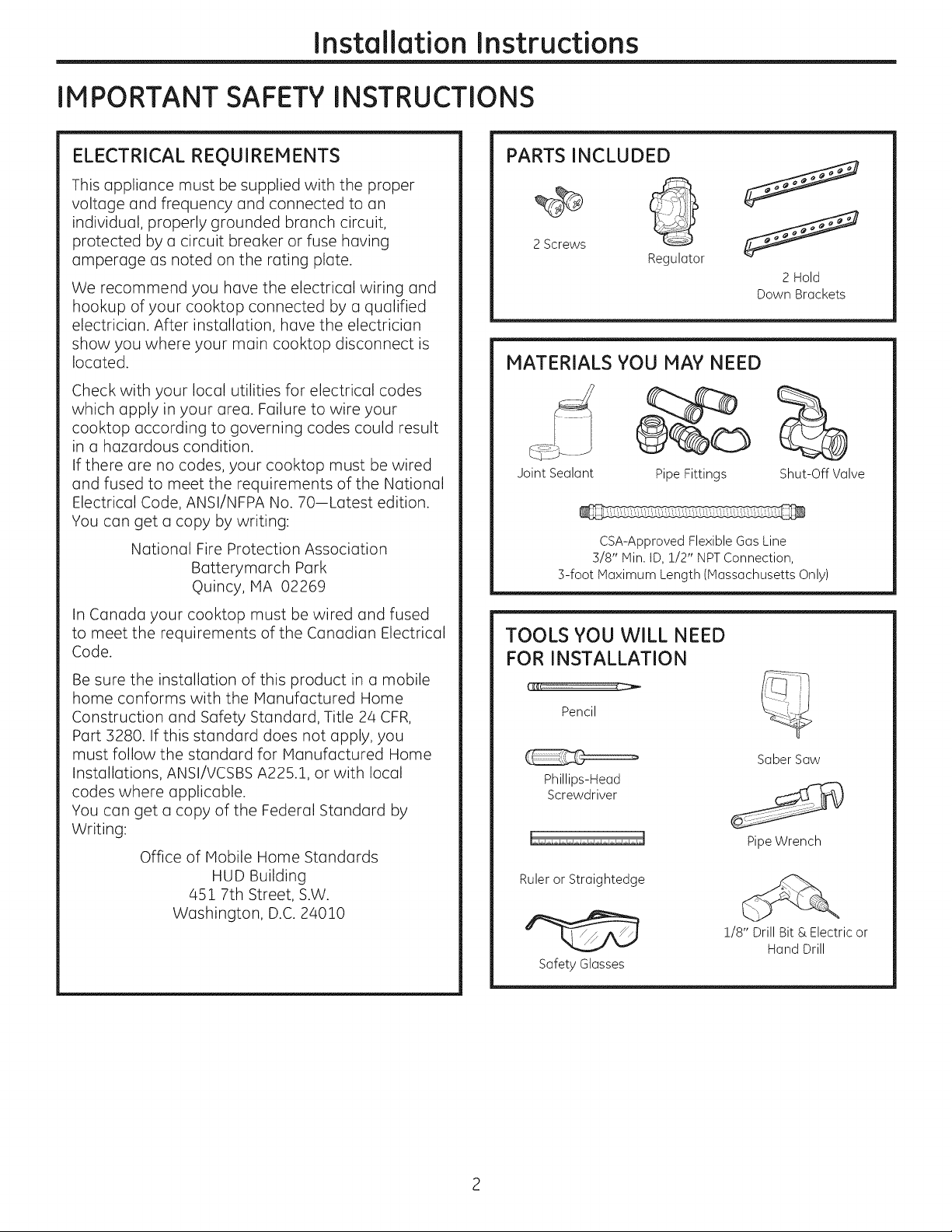
PARTS INCLUDED
2Screws
Regulator
MATERIALS YOU MAY NEED
Joint Sealant Pipe Fittings
CSA-Approved Flexible Gas Line
3/8" Min. ID, 1/2" NPTConnection,
3-foot Maximum Length (Massachusetts Only)
2 Hold
Down Brackets
Shut-Off Valve
In Canada your cooktop must be wired and fused
to meet the requirements of the Canadian Electrical
Code.
Be sure the installation of this product in a mobile
home conforms with the Manufactured Home
Construction and Safety Standard, Title 24 CFR,
Part 3280. If this standard does not apply, you
must follow the standard for Manufactured Home
Installations, ANSI/VCSBS A225.1, or with local
codes where applicable.
You can get a copy of the Federal Standard by
Writing:
Office of Mobile Home Standards
HUD Building
451 7th Street, S.W.
Washington, D.C. 24010
TOOLS YOU WILL NEED
FOR INSTALLATION
Pencil
Saber Saw
Phillips-Head
Screwdriver
Pipe Wrench
Ruler or Straightedge
1/8" Drill Bit & Electric or
Hand Drill
Safety Glasses
Page 3
Installation Instructions
PRE-INSTALLATION CHECKLIST
When preparing cooktop opening, make
[Z]
sure the inside of the cabinet and the
cooktop do not interfere with each other.
(See section on preparing the opening.)
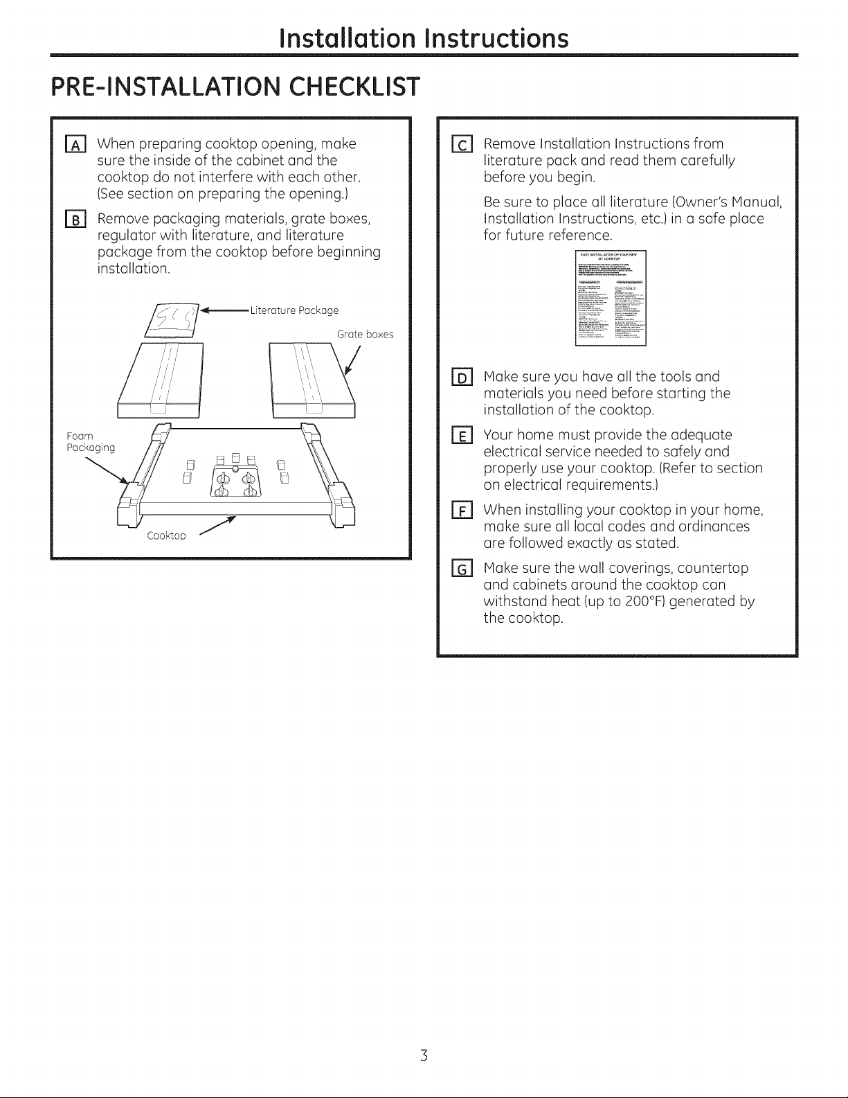
Remove packaging materials, grate boxes,
@
regulator with literature, and literature
package from the cooktop before beginning
installation.
i'/
/i/
Foam_ _
Pac / _ _ _ E]
Cooktop J
Package
Grate boxes
Remove Installation Instructions from
E1
literature pack and read them carefully
before you begin.
Be sure to place all literature (Owner's Manual,
Installation Instructions, etc.)in a safe place
for future reference.
Make sure you have all the tools and
El
materials you need before starting the
installation of the cooktop.
Your home must provide the adequate
El
electrical service needed to safely and
properly use your cooktop. (Refer to section
on electrical requirements.)
When installing your cooktop in your home,
FF1
make sure all local codes and ordinances
are followed exactly as stated.
Make sure the wall coverings, countertop
[]
and cabinets around the cooktop can
withstand heat (up to 200°F) generated by
the cooktop.
Page 4
Installation Instructions
PREPARING THE OPENING
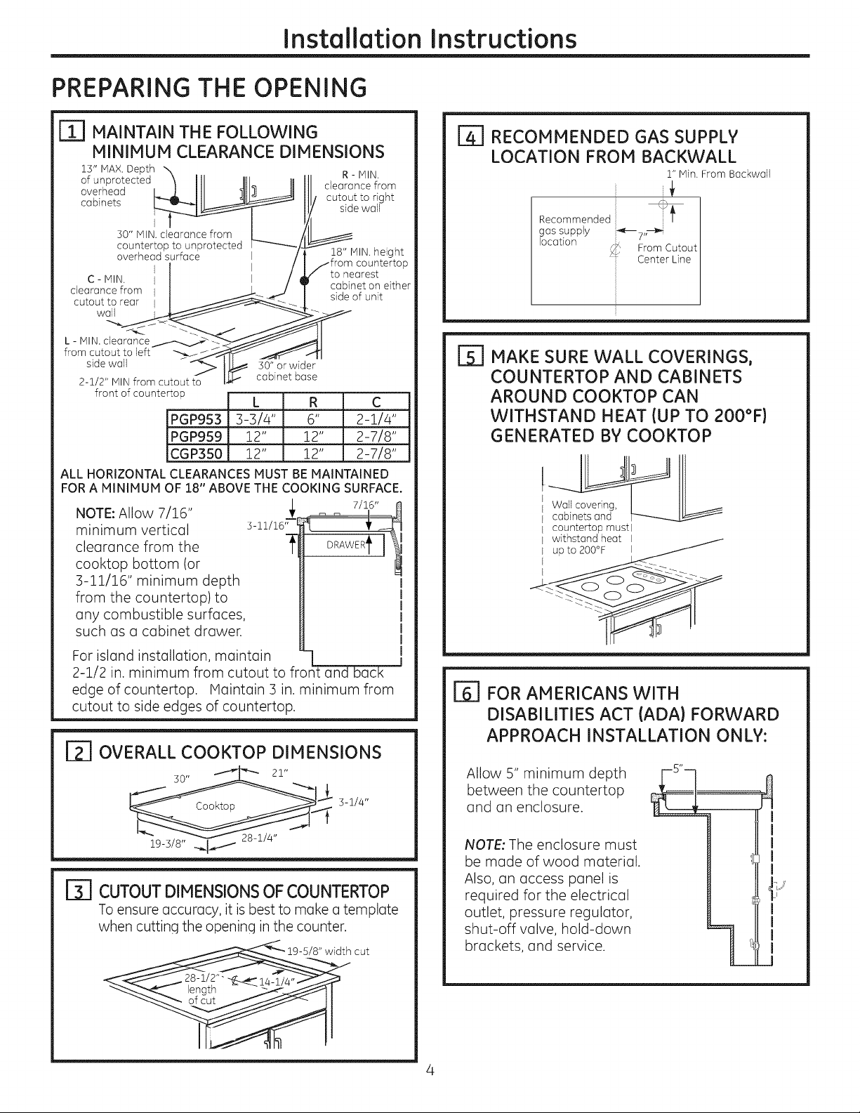
r_ MAINTAIN THE FOLLOWING
MINIMUM CLEARANCE DIMENSIONS
13" MAX.Depth
of unprotected
overhead
cabinets
I
30" MIN. clearance from
countertop to unprotected
overhead surface
C - MIN, I
clearance from I
cutout to rear
wall
L - MIN. clearance
from cutout to left
side wall 30" or wider
2-1/2" MIN from cutout to
front of counterto u
ALL HORIZONTAL CLEARANCES MUST BE MAINTAINED
FOR A MINIMUM OF 18" ABOVE THE COOKING SURFACE.
NOTE: Allow 7/16"
minimum vertical
clearance from the
cooktop bottom (or
3-11/16" minimum depth
from the countertop) to
any combustible surfaces,
such as a cabinet drawer.
I
cabinet base
L R C
PGP953 3-3/4" 6" 2-i/4"
PGP959 12" 12" 2-718"
CGP350 12" 12" 2-7/8"
R - IV]IN,
clearance from
cutout to right
side wall
18" MIN. height
countertop
to nearest
cabinet on either
side of unit
I_ RECOMMENDED GAS SUPPLY
LOCATION FROM BACKWALL
r' Min. From Backwall
Recommended
gas supply
location
From Cutout
Center Line
r_ MAKE SURE WALL COVERINGS,
COUNTERTOP AND CABINETS
AROUND COOKTOP CAN
WITHSTAND HEAT (UP TO 200°F)
GENERATED BY COOKTOP
Wallcovering,
cabinets and
countertop mustl
withstand heat I
For island installation, maintain
2-1/2 in. minimum from cutout to front and back
edge of countertop. Maintain 3 in. minimum from
cutout to side edges of countertop.
I_ OVERALL COOKTOP DIMENSIONS
30" _i _ 21"
_-- v 28-1J4"
19-3/8" _1 /
F31 CUTOUTDIMENSIONSOFCOUNTERTOP
To ensure accuracy, it is best to make a template
when cuttinq the openinq in the counter.
/8" width cut
F61 FOR AMERICANS WITH
DISABILITIES ACT (ADA) FORWARD
APPROACH INSTALLATION ONLY:
Allow 5" minimum depth
between the countertop
and an enclosure.
NOTE: The enclosure must
be made of wood material.
Also, an access panel is
required for the electrical
outlet, pressure regulator,
shut-off valve, hold-down
brackets, and service.
ii
]J
l
Page 5
Installation Instructions
iNSTALLiNG THE COOKTOP UNiT
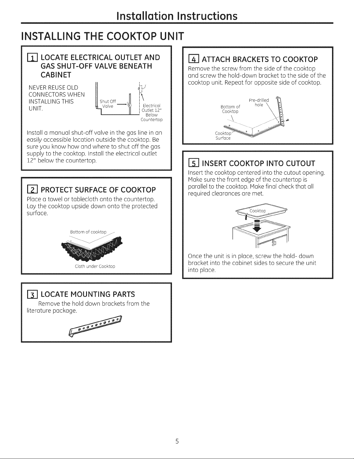
LOCATE ELECTRICAL OUTLET AND
IT]
GAS SHUT-OFF VALVE BENEATH
CABINET
NEVER REUSEOLD
CONNECTORS WHEN
INSTALLING THIS
UNIT.
H i
Shut Off t
_Va]ve g_ ', E,ectrical
17/
U
I Outlet 12"
Below
Countertop
[][] ATTACH BRACKETS TO COOKTOP
Remove the screw from the side of the cooktop
and screw the hold-down bracket to the side of the
cooktop unit. Repeat for opposite side of cooktop.
Pre-dfilled
Bottom of hole X _/
Cooktop .y-_'-x "
Install a manual shut-off valve in the gas line in an
easily accessible location outside the cooktop. Be
sure you know how and where to shut off the gas
supply to the cooktop. Install the electrical outlet
12" below the countertop.
_] PROTECT SURFACE OF COOKTOP
Place a towel or tablecloth onto the countertop.
Lay the cooktop upside down onto the protected
surface.
Bottom of cooktop f
Cloth under Cooktop
r_ LOCATE MOUNTING PARTS
Remove the hold down brackets from the
literature package.
Coo
Surface
r_ INSERT COOKTOP INTO CUTOUT
Insert the cooktop centered into the cutout opening.
Hake sure the front edge of the countertop is
parallel to the cooktop. Hake final check that all
required clearances are met.
Once the unit is in place, screw the hold- down
bracket into the cabinet sides to secure the unit
into place.
Page 6
Installation Instructions
INSTALLATION--GAS CONNECTIONS
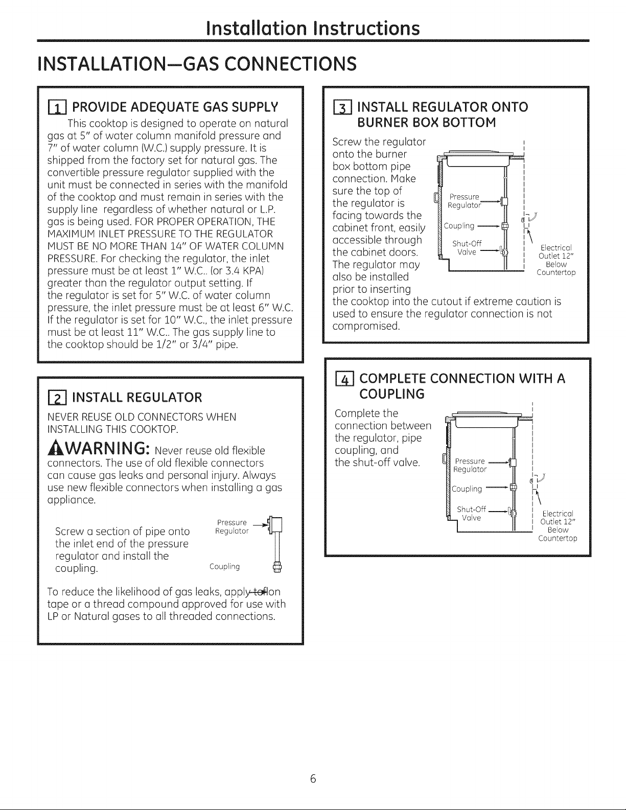
r_ PROVIDE ADEQUATE GAS SUPPLY
This cooktop is designed to operate on natural
gas at 5" of water column manifold pressure and
7" of water column (W.C.) supply pressure. It is
shipped from the factory set for natural gas. The
convertible pressure regulator supplied with the
unit must be connected in series with the manifold
of the cooktop and must remain in series with the
supply line regardless of whether natural or L.P.
gas is being used. FOR PROPEROPERATION, THE
MAXIMUM INLET PRESSURETO THE REGULATOR
MUST BE NO MORE THAN 14" OF WATER COLUMN
PRESSURE.For checking the regulator, the inlet
pressure must be at least 1" W.C.. (or 3.4 KPA)
greater than the regulator output setting. If
the regulator is set for 5" W.C. of water column
pressure, the inlet pressure must be at least 6" W.C.
If the regulator is set for 10" W.C., the inlet pressure
must be at least 11" W.C.. The gas supply line to
the cooktop should be 1/2" or 3/4" pipe.
[_] INSTALL REGULATOR
NEVER REUSEOLD CONNECTORS WHEN
INSTALLING THIS COOKTOP.
AWARNING: Never reuse old flexible
connectors. The use of old flexible connectors
can cause gas leaks and personal injury. Always
use new flexible connectors when installing a gas
appliance.
Screw a section of pipe onto
the inlet end of the pressure
regulator and install the
coupling.
Regulator
Pressure __?
Coupling
r3] INSTALL REGULATOR ONTO
BURNER BOX BOTTOM
Screw the regulator
onto the burner
box bottom pipe
connection. Make
sure the top of
the regulator is
Pressure _1
Regulator'----'_l
facing towards the
cabinet front, easily
accessible through
the cabinet doors.
The regulator may
also be installed
Coupling l
LI
:\
Ii Electrical
II Outlet 12"
I Below
Countertop
prior to inserting
the cooktop into the cutout if extreme caution is
used to ensure the regulator connection is not
compromised.
r_ COMPLETE CONNECTION WITH A
COUPLING
Complete the
connection between
the regulator, pipe
coupling, and
the shut-off valve.
Pressure
Regulator
Coupling
Shut-Off _/]
Valve
I
II
II Electrical
I Outlet 12"
I Below
Countertop
To reduce the likelihood of gas leaks, apply4-eilon
tape or a thread compound approved for use with
LP or Natural gases to all threaded connections.
Page 7

Installation Instructions
[_ CHECK FOR LEAKS
LEAKTESTINGOF THE APPLIANCE SHALL BE
CONDUCTED ACCORDING TO THE MANUFACTURER'S
INSTRUCTIONS.
Before testing for leaks, make sure all burner knobs
are in the OFF position.
After connecting the cooktop to gas, check system
for leaks with o manometer. If o manometer is not
available, turn the gas supply on to the cooktop
and use o liquid leak detector at oil joints and
connections to check for leaks.
Tighten oll connections if necessory to prevent gas
leokage in the cooktop or supply line.
DO NOT USE OPEN FLAME TO CHECK FOR
LEAKS!
Disconnect the cooktop ond its individuol shut-off
volve from the gos supply piping system during any
pressure testing of that system at test pressures
greater thon 1/2 psig (3.5 kPo).
Isolote the cooktop from the gas supply piping
system by closing its individual shut-off valve
during any pressure testing of the gas supply
system ot test pressures equol to or less thon 1/2
psig (3.5 kPo).
[_] INSTALLATION OVER BUILT-IN
OVEN
See built-in oven installation for complete
installation instructions.
1
__1_ s,,ToCenterof
I _ _ 2" Dia. Hole From
_ Countertop
_- 2" DiG. Hole
L_ (20 7/8" from front
{_¢_b,'4 Hole Center)
Cabinet Sides ..... J v_4"\_l
View from Front of Cooktop
of Countertop to
Page 8
Installation Instructions
INSTALLATION--ELECTRICAL CONNECTIONS
, WARNING - Disconnect all electrical
power at the main circuit breaker or fuse box
before installing.
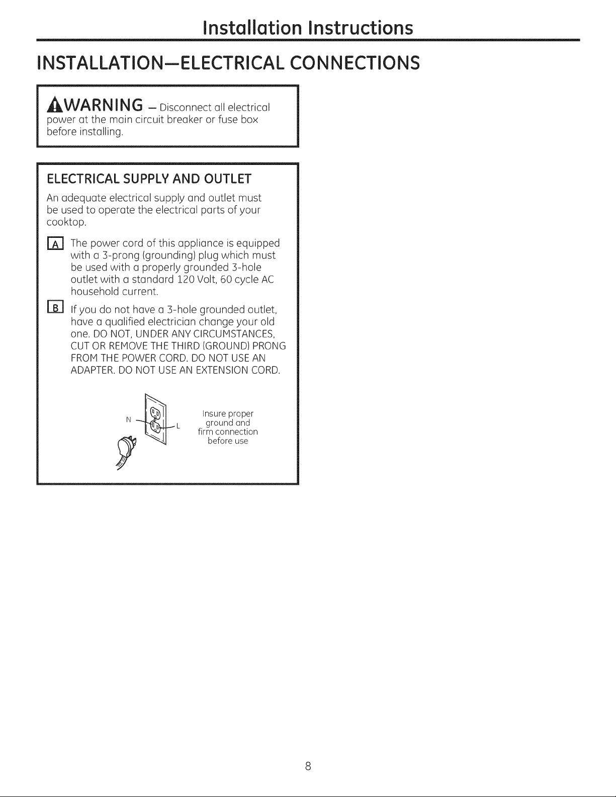
ELECTRICAL SUPPLY AND OUTLET
An adequate electrical supply and outlet must
be used to operate the electrical parts of your
cooktop.
[]
The power cord of this appliance is equipped
with a 5-prong (grounding) plug which must
be used with a properly grounded 5-hole
outlet with a standard 120 Volt, 60 cycle AC
household current.
B]
If you do not hGve G 5-hole grounded outlet,
have a qualified electrician change your old
one. DO NOT, UNDER ANY CIRCUMSTANCES,
CUT OR REMOVE THE THIRD (GROUND) PRONG
FROM THE POWER CORD. DO NOT USE AN
ADAPTER. DO NOT USE AN EXTENSION CORD.
Insure proper
ground and
firm connection
before use
Page 9

Installation Instructions
COOKTOP BURNERS
E_ ASSEMBLING THE COOKTOP BURNERS
The electrode of the igniter is exposed. Be careful not to turn on any cooktop controls
while the top of the burner is removed. Do not remove the top or touch the electrode
of any burner while another burner is turned on. Electrical shock might result.
[] Place the burner head onto the burner base. Make sure to place the correct
burner head on the correct burner base and that the burner head sits level on
the burner base. The burner heads are not interchangeable. Ensure the slot in
the burner head is positioned over the electrode and that the burner head is
fully inserted inside the burner base. A small gap between the base and head is
normal.
Place the burner caps on the burner heads, making sure to place the correct
[]
burner cap on the correct burner head. The burner caps are not
interchangeable. Each cap has three to four pins. Make sure that the burner
caps are properly seated on the burner heads and that none of the pins sit in the stability chamber.
Burner capproperly seated
Burner capnot properly seated
OR
Burner
base
Burner
base
[_ CHECK IGNITERS
Operation of the electric igniters should be checked after the cooktop and supply line have been carefully
checked for leaks and the cooktop has been connected to the electrical power.
On models so equipped, check to be sure the cooktop is in the UNLOCKED position.
rA1 Push and turn a burner valve to the LITE position. All spark igniters will make a series of sparks (ticking
sounds), but only the burner turned to LITE will light.
. The burner should light when gas is available to the burner.
. Once the burner lights, it should be turned out of the LITE position.
r_ Try each valve separately until all burners have been checked.
Page 10
Installation Instructions
COOKTOP BURNERS (CONT.)
ITI BURNER IGNITION
Cooktop Spark Ignition-When you turn the
cooktop knob to LITE, the spark igniter makes a
series of electric sparks (ticking sounds) which light
the burner. During a power failure, the burners will
not light automatically. In an emergency, a cooktop
burner may be lit with a match by following the
steps below.
On models so equipped, check to be sure the
cooktop is in the UNLOCKED position.
EA1 Light a match and hold the flame near the
burner you want to light. Wooden matches
work best.
r_ Push in and turn the control knob slowly. Be
sure you are turning the correct knob for the
burner you are lighting.
NOTE: If the burner does not light within five seconds,
turn the knob off and wait one minute before trying
again.
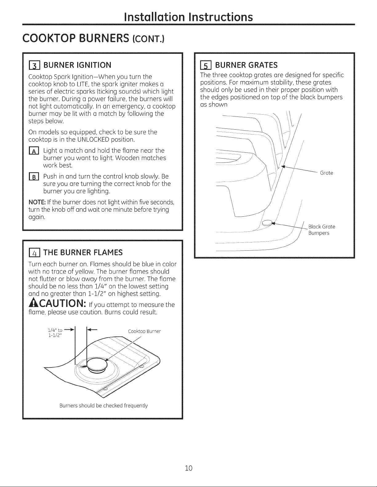
[_] BURNER GRATES
The three cooktop grates are designed for specific
positions. For maximum stability, these grates
should only be used in their proper position with
the edges positioned on top of the black bumpers
as shown
/
//
//
//'
Grate
/
/
/
/ /
/
//
/
/
/
Black Grate
Bumpers
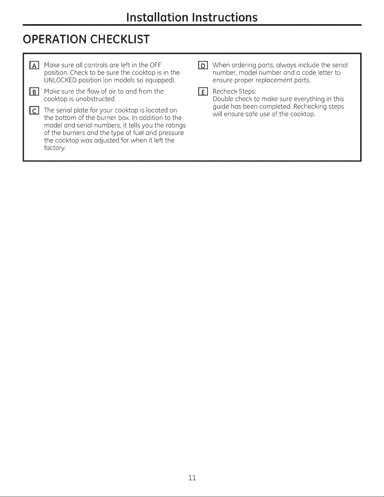
r_] THE BURNER FLAMES
Turn each burner on. Flames should be blue in color
with no trace of yellow. The burner flames should
not flutter or blow away from the burner. The flame
should be no less than 1/4" on the lowest setting
and no greater than 1-1/2" on highest setting.
• IkCAUTION: ifyou attempt to meosure the
flame, please use caution. Burns could result.
i/4" to
i-i/2"
Burners should be checked frequently
Cooktop Burner
10
Page 11
Installation Instructions
OPERATION CHECKLIST
r_ Moke sure all controls ore left in the OFF r_
position. Check to be sure the cooktop is in the
UNLOCKED position (on models so equipped).
Plake sure the flow of air to and from the
cooktop is unobstructed.
The serial plate for your cooktop is located on
the bottom of the burner box. In addition to the
model and serial numbers, it tells you the ratings
of the burners and the type of fuel and pressure
the cooktop was adjusted for when it left the
factory.
B]
When ordering parts, always include the serial
number, model number and a code letter to
ensure proper replacement parts.
Recheck Steps:
Double check to make sure everything in this
guide has been completed. Rechecking steps
will ensure safe use of the cooktop.
11
Page 12
Installation Instructions
MAKING THE LP CONVERSION
r_ SAFETY INFORMATION YOU
SHOULD KNOW
The pressure regulator and burner orifices are set
for natural gas. To use LP gas, the regulator and
burner orifices must be converted. The LP orifice
spuds for the cooktop burners are attached to
the regulator along with separate LP conversion
instructions.
At- ^, ,,T,,,,_ L,
,_I:L_.,,/RU/IU I_: The cooktop, as shipped from
the factory, is set for use with natural gas. If you
wish to use your cooktop with LPgas, you must
first replace the orifices and convert the pressure
regulator.
AIlI_W/"_I'II_i I i_1_: This conversion must be
performed by a qualified installer or gas supplier in
accordance with the manufacturer's instructions
and all codes and requirements of the authority
having jurisdiction. Failure to follow instructions
could result in serious injury or property damage.
The qualified agency performing this work assumes
responsibility for the conversion.
_IL_,,,/_U/|UI_I: The following adjustments
must be made before turning on the burner. Failure
to do so could result in serious injury. Be sure
pressure regulator has been converted as
described in Step 2.
TOOLS YOU WILL NEED
FOR LP CONVERSION
7mm Nutdriver
Safety Glosses
Small Flat-Head
Screwdriver (4mm or
5/32" tip size,60mm or
2-3/8" long)
ADJUST YOUR COOKTOP FOR USE
[2]
WITH LP GAS
Disconnect all electrical power, at the main
circuit breaker or fuse box.
B]
Shut off the gas supply to the cooktop
by closing the manual shut-off valve.
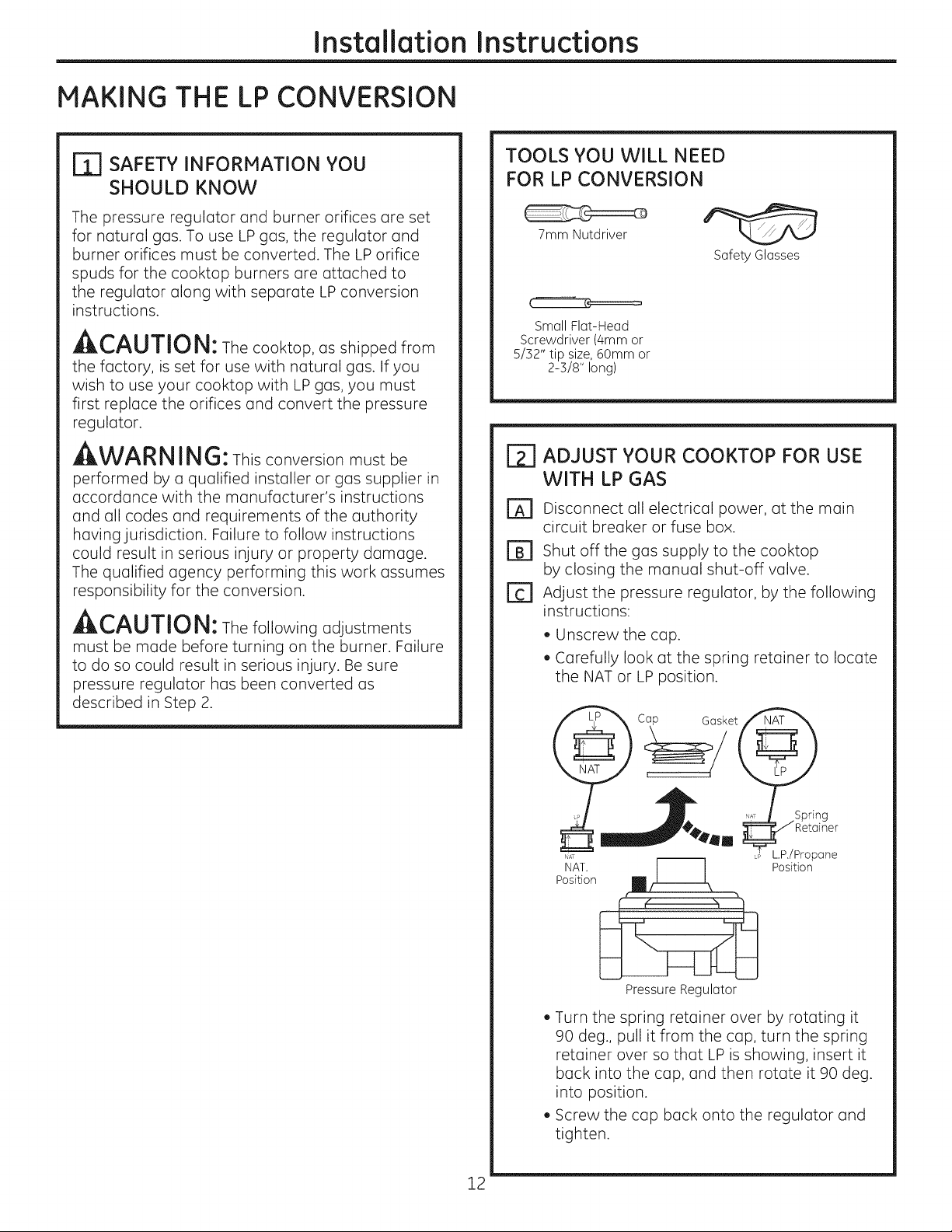
Adjust the pressure regulator, by the following
Fa
instructions:
, Unscrew the cap.
, Carefully look at the spring retainer to locate
the NAT or LP position.
12
Position
NAT. _ Position
Pressure Regulator
. Turn the spring retainer over by rotating it
90 deg., pull it from the cap, turn the spring
retainer over so that LP is showing, insert it
back into the cap, and then rotate it 90 deg.
into position.
. Screw the cap back onto the regulator and
tighten.
Page 13
Installation Instructions
MAKING THE LP CONVERSION (CONT.)
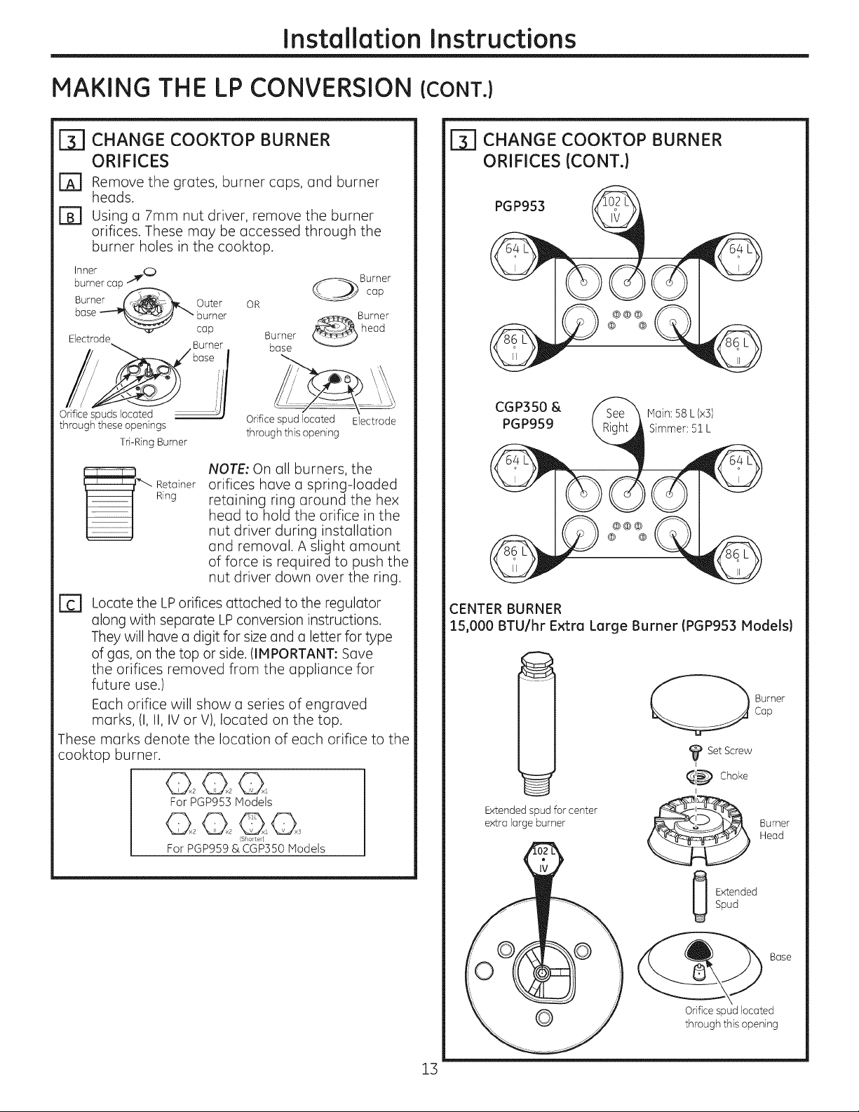
[_ CHANGE COOKTOP BURNER
ORIFICES
FA1 Remove the grates, burner caps, and burner
heads.
[] Using a 7mm nut driver, remove the burner
orifices. These may be accessed through the
burner holes in the cooktop.
Inner /._(;_ A"----_"_"_ Burner
burner cop
Burner _f_ Outer OR \_ cop
base __''_ burner _S_ Burner
Electrode Burner base
Orifice spuds located J/ Orifice spud located Electrode
through these openings through this opening
Tri-Ring Burner
cap Burner head
NOTE: On all burners, the
Retainer
Ring
orifices have a spring-loaded
retaining ring around the hex
head to hold the orifice in the
nut driver during installation
and removal. A slight amount
of force is required to push the
nut driver down over the ring.
CHANGE COOKTOP BURNER
ORIFICES (CONT.)
PGP953
@@@
@ @
CGP350 &
PGP959
@@@
@ @
Main:58L (x3)
Simmer:5! L
Fcl Locate the LP orifices attached to the regulator
along with separate LPconversion instructions.
They will have a digit for size and a letter for type
of gas, on the top or side. (IMPORTANT: Save
the orifices removed from the appliance for
future use.)
Each orifice will show a series of engraved
marks, (I, II, IV or V), located on the top.
These marks denote the location of each orifice to the
cooktop burner.
O>.,20>.,20>.,1
For PGP953 Hodels
For PGP9S9& CGP3SOModels
(Shorter)
CENTER BURNER
15,000 BTU/hr Extra Large Burner (PGP953 Models)
Cap
Burner
Set Screw
I
_(_ Choke
I
Extended spud for center
extra large burner
I
Burner
Head
Spud
Extended
Orifice spud located
through this opening
Base
13
Page 14
Installation Instructions
r_ CHANGE COOKTOP BURNER
ORIFICES (CONT.)
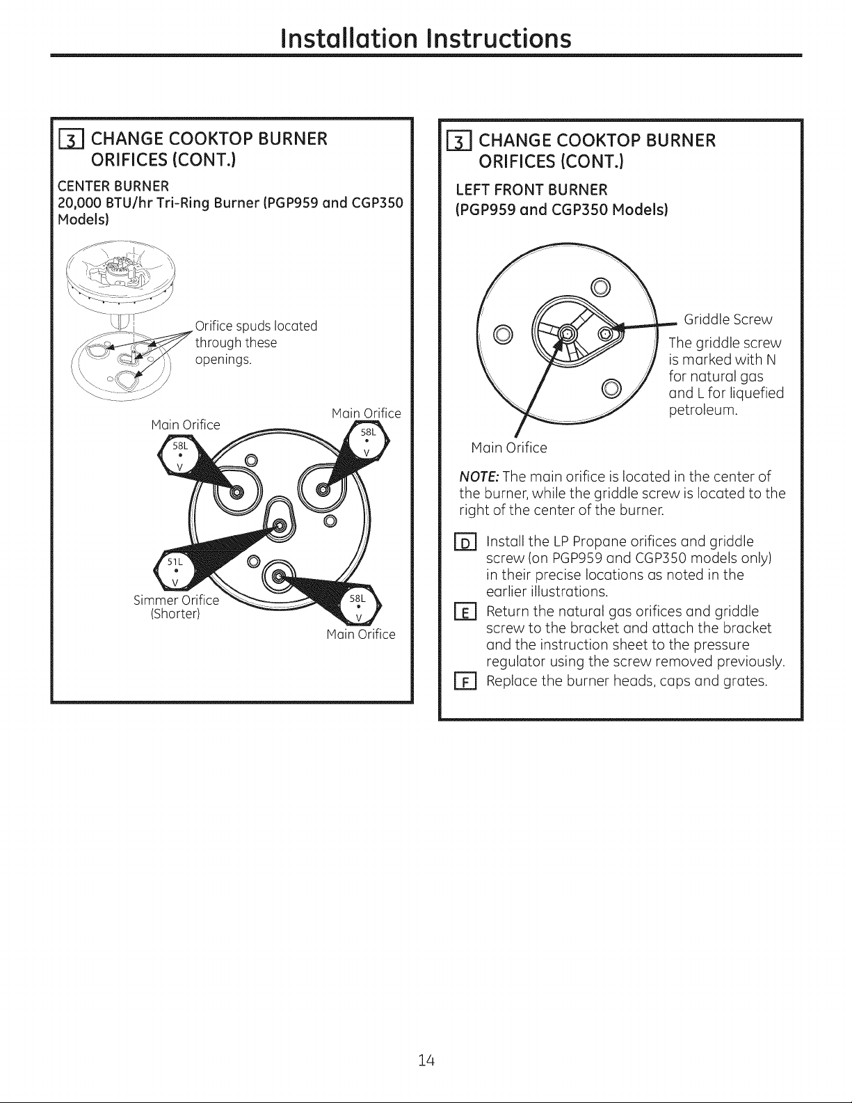
CENTER BURNER
20,000 BTU/hr Tri-Ring Burner (PGP959 and CGP350
Models)
r
r_ CHANGE COOKTOP BURNER
ORIFICES (CONT.)
LEFT FRONT BURNER
(PGP959 and CGP350 Models)
through these
openings.
Main Orifice
Simmer Orifice
(Shorter)
spuds located
Hain Orifice
Main Orifice
Griddle Screw
The griddle screw
is marked with N
for natural gas
and L for liquefied
petroleum.
Main Orifice
NOTE: The main orifice is located in the center of
the burner, while the griddle screw is located to the
right of the center of the burner.
Install the LP Propane orifices and griddle
rB]
screw (on PGPgS9 and CGP3S0 models only)
in their precise locations as noted in the
earlier illustrations.
r_ Return the natural gas orifices and griddle
screw to the bracket and attach the bracket
and the instruction sheet to the pressure
regulator using the screw removed previously.
r_ Replace the burner heads, caps and grates.
14
Page 15
Installation Instructions
MAKING THE LP CONVERSION (CONT.)
ADJUST BURNER FLAMES
Turn all burners full on and check the flames.
[]
They should be blue in color with some yellow
tipping at the ends of the flame. Foreign
particles in the gas line may cause an orange
flame at first, but this will soon disappear.
r_ Turn the cooktop burner knob to the lowest
setting while observing the flame.
Adjust the low flame setting using the valve bypass
screw as follows:
Low-setting adjustments must be made with two
other burners in operation on a medium setting.
This prevents the low flame from being set too low,
resulting in the flame being extinguished when
other burners are turned on.
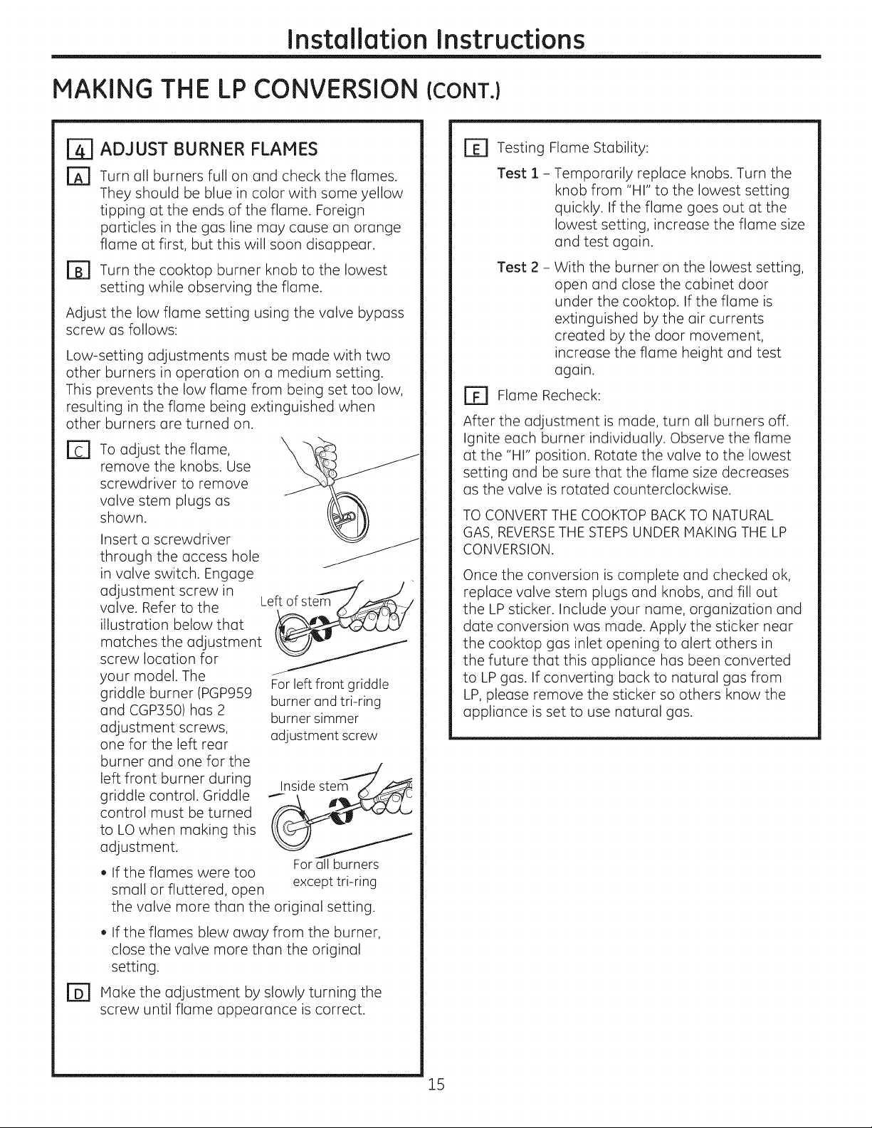
E1 To adjust the flame,
remove the knobs. Use
screwdriver to remove
valve stem plugs as
shown.
Insert a screwdriver
through the access hole
in valve switch. Engage
adjustment screw in
valve. Refer to the
illustration below that
matches the adjustment
screw location for
your model. The
griddle burner (PGP959
and CGP3501 has 2
adjustment screws,
one for the left rear
burner and one for the
left front burner during
griddle control. Griddle
control must be turned
to LO when making this
adjustment.
, If the flames were too
small or fluttered, open
the valve more than the original setting.
Left of stem
For left front griddle
burner and tri-ring
burner simmer
adjustment screw
For all burners
except tri-ring
r_ Testing Flame Stability:
Test 1 - Temporarily replace knobs. Turn the
knob from "HI" to the lowest setting
quickly. If the flame goes out at the
lowest setting, increase the flame size
and test again.
Test 2 -
El Flame Recheck:
After the adjustment is made, turn all burners off.
Ignite each burner individually. Observe the flame
at the "HI" position. Rotate the valve to the lowest
setting and be sure that the flame size decreases
as the valve is rotated counterclockwise.
TO CONVERT THE COOKTOP BACK TO NATURAL
GAS, REVERSETHE STEPSUNDER MAKING THE LP
CONVERSION.
Once the conversion is complete and checked ok,
replace valve stem plugs and knobs, and fill out
the LP sticker. Include your name, organization and
date conversion was made. Apply the sticker near
the cooktop gas inlet opening to alert others in
the future that this appliance has been converted
to LP gas. If converting back to natural gas from
LP, please remove the sticker so others know the
appliance is set to use natural gas.
With the burner on the lowest setting,
open and close the cabinet door
under the cooktop. If the flame is
extinguished by the air currents
created by the door movement,
increase the flame height and test
again.
, If the flames blew away from the burner,
close the valve more than the original
setting.
r_ Make the adjustment by slowly turning the
screw until flame appearance is correct.
15
Page 16

Notes.
16
Page 17

I struction
Ta le de cuJsson scell
d'i stallat"
au gaz de 76 cm (30")
PGP953, PGP959, CGP350
Web 8 I'adresse : www.electromenagersge.ca
AVANT DE COMMENCER
Avant de commencer, lisez attentivement la totalit6
de ces instructions.
.IMPORTANT - Conservezces
instructions pour votre inspecteur local.
" IMPORTANT - Respectez toutes les
ordonnances et les codes Iocaux.
, Note 6 I'installateur - Assurez-vous de laissez ces
instructions au consommateur.
, Note au consommateur - Conservez ces
instructions pour r6f@ence future.
, La garantie ne couvre aucune panne due
6 une mauvaise installation.
AAVERTISSEMENT -
Cet appareil doit @tre bien mis 6 la terre.
. IMPORTANT - vousdevezv@ifierque
cet appareil n'ait pas de fuite conform6ment aux
instructions du fabricant.
, L'installateur est responsable d'une bonne
installation et la garantie ne couvre aucune
panne due 6 une mauvaise installation.
A AVERTISSEMENT - D6brancheztout
courant61ectriqueau niveaudu disjoncteurde la
maison ou de la boTte6 fusiblesavant d'installer.
POUR VOTRE Si_CURITI_
AAVERTISSEMENT -
si vous ne suivez pas exactement les instructions
de ce manuel, vous risquez d'occasionner un
incendie, une explosion ou une fuite de gaz, qui
peuvent provoquer des dommages mat@iels, des
blessures corporelles ou la mort.
Ne conservez pas ou n'utilisezjamais d'essence
ou d'autres liquides ou vapeurs inflammables 6
proximit6 de cet appareil ou de tout autre appareil
m6nager!
Ne pas installer ce produit si I'on utilise une hotte 6
rideau d'air ou une hotte de cuisini_re soufflant I'air
au-dessus de la surface de cuisson. Le d6bit d'air
peut nuire au fonctionnement des brOleurs 6 gazet
repr6sente un risque d'incendie ou d'explosion.
CI QUE VOUS DEVEZ FAIRE SI
VOUS SENTEZ LE GAZ •
, N'essayezjamais d'allumer un appareil
61ectrom6nager. Ne touchez 6 aucun
commutateur d'61ectricit6, n'utilisezjamais un
t616phonedans votre batiment.
, Appelez imm6diatement votre fournisseur de
gaz 6 I'aide du t616phoned'un raisin. Suivez les
instructions de votre fournisseur de gaz.
, Sivous ne pouvez pas entrer en contact avec
votre fournisseur de gaz, appelez lespompiers.
L'installation et le service de votre table de cuisson
doivent _tre faits par un installateur qualifi6, un
technicien de service ou votre fournisseur de gaz.
31-i0858-i (08-12 GE) 1
Page 18

Instructions d'installation
INSTRUCTIONS IMPORTANTES DE SI CURITI
Cette table de cuisson a 6t6 homologu6e UL Vous
trouverez des pr6cautions 6 prendre en mati6re de
s6curit6 dans votre Guide d'utilisation et de soins.
Lisez-les attentivement.
, L'installation de votre table de cuisson dolt se
conformer aux codes Iocaux ou, en I'absence de
codes Iocaux, au National Fuel Gas Code, ANSI
Z223.1/NFPA 54 Derni@e 6dition.
, Assurez-vous que votre table de cuisson soit
bien install6e par un installateur qualifi6 ou un
technicien de service.
, Pour 61iminer tout mouvement corporel au dessus
des brQleurs de votre table de cuisson, 6vitez de
placer des armoires de cuisine au dessus des
brQleurs.
, N'installezjamais votre appareil pros d'une porte
d'entr6e ou dans un emplacement oQ un courant
d'air peut g6ner son usage.
BESOINS D'ELECTRICITE
PII_CESCOMPRISES
2vis R6gulateur 2 Supportsde fixation
MATI_RIAU× DONT VOUS POUVEZ
AVOIR BESOIN
Agent de scellement
de tuyau
Raccord flexible de gaz approuv6 par I'ACNOR
Raccords de tuyau×
DI min 3/8", Jonction NPT1/2
Robinet d'alimentation
de gaz
Cet appareil m6nager doit @tre livr6 avec le bon
voltage et la bonne fr6quence et branch6 6 son
propre circuit de d6rivation bien mis 6 la terre,
prot6g6 par un disjoncteur ou un fusible qui ont
I'amp6rage not6 sur la plaque min6ralogique de
votre appareil.
Nous vous recommandons de faire brancher le
c_blage 61ectrique et la fiche de votre cuisini@re
par un 61ectricien qualifi6. Apr6s I'installation,
demandez 6 1'61ectricien de vous montrer
I'emplacement de votre coupe-circuit principal.
Demandez 6 votre entreprise de services publics les
codes 61ectriques en vigueur dans votre r6gion. En
ne c_blant pas votre cuisini6re conform6ment aux
codes en vigueur, vous provoquez une situation
dangereuse. En I'absence de codes, vous devez
c_]bler et isoler votre cuisini@e conform6ment aux
exigences du Canadian Electrical Code.
OUTILS DONT VOUS AUREZ BESOINS
Crayon
Scie sauteuse
Tournevis Phillips
R_gle ordinaire ou de
v@ification
Lunettes de s6curit6
CI66 tuyau
Perceuse 6 main ou 61ectrique
et foret de !/8po
Page 19

Instructions d'installation
LISTE
Pour pr6parer I'ouverture de la surface de
[]
cuisson, vous devez vous assurer que
I'int6rieur de I'armoire ne touche pas la table
de cuisson (consultez la section sur la
pr6paration de I'ouverture).
Enlevez les mat6riau× d'emballage, les
@
boTtes de grille, le r6gulateur avec sa
documentation et la documentation de
votre table de cuisson avant de commencer
5 I'installer.
DE VITRIFICATION AVANT INSTALLATION
Enlevez les instructions d'installation de la
D
trousse de documentation et lisez-les
soigneusement avant de commencer.
Assurez-vous de bien ranger toute la
documentation,(Hanuel du propri6taire,
Instructions d'installation, etc.) dans un
endroit sQr pour r6f6rence future.
_ Documentation
Bo_tesde
grille
/
Assurez-vous d'avoir tous les outils et tous
@
les mat@raux n@cessaires avant de
commencer 5 installer votre table de
cuisson.
r_ votre maison dolt 6tre aliment6e en courant
61ectrique ad@quat pour vous permettre de
bien utiliser en toute s@curit6 votre table de
cuisson. (Consultez la section sur les besoins
d'61ectricit@.)
cuisson
r_ Pour installer votre table de cuisson dans
votre maison, assurez-vous de vous
conformer scrupuleusement _ tousles
codes et 5 toutes les ordonnances locales.
Assurez-vous que les rev@tements de mur, le
[]
comptoir et les armoires autour de la table
de cuisson puissent supporter la chaleur
[pouvant atteindre 93°C (200°F)] produite
par la table de cuisson.
Page 20
Instructions d'installation
PREPARATION DE L'OUVERTURE
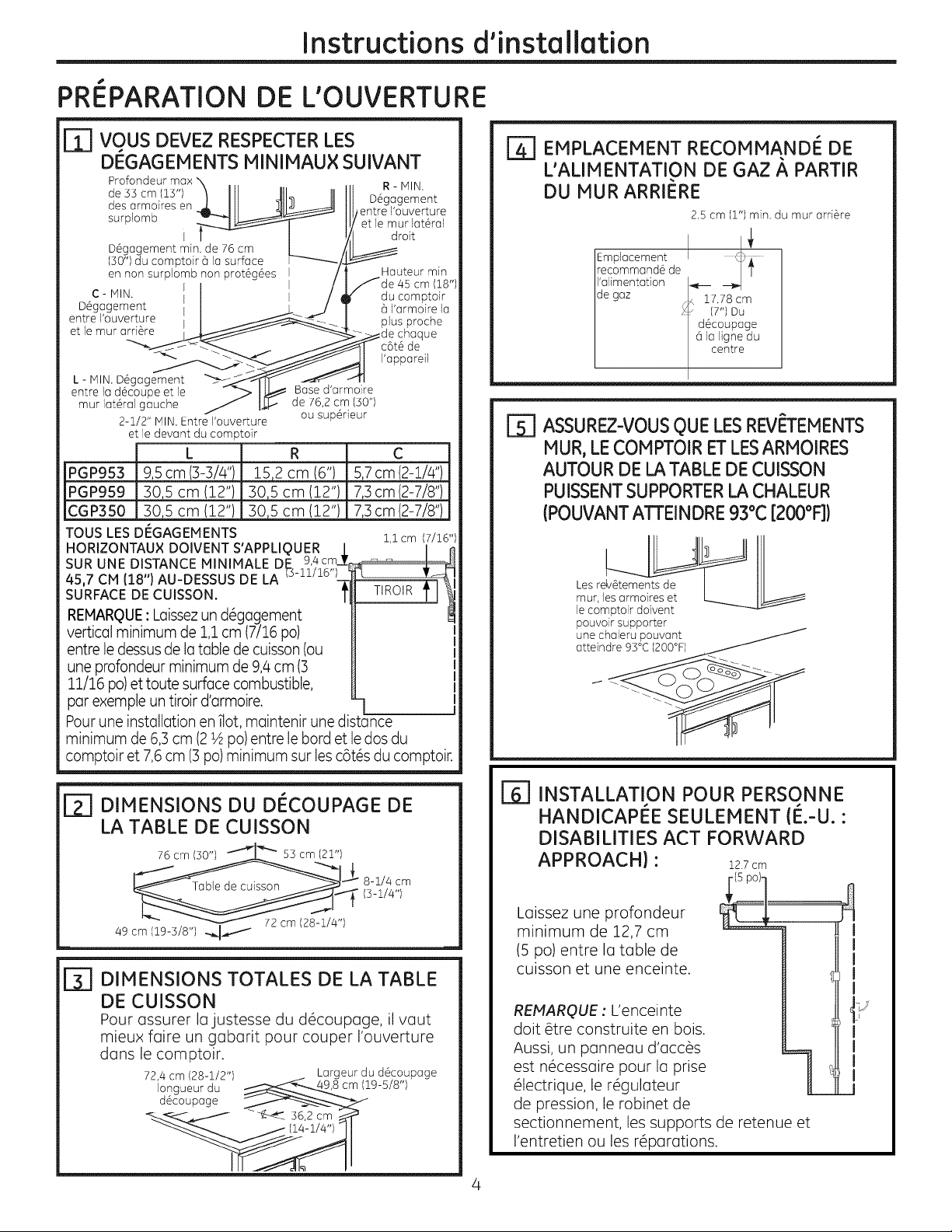
r_] vous DEVEZ RESPECTERLES
DEGAGEMENTS MINIMAUX SUIVANT
Profondeur max x R - MIN.
des armoires en __L
de]]cm(1]') . __ i D#gagemen t
surplomb _ I/entre I'ouverture
! et lemur lat#ral
_t I droit
D#gagement min. de 76 cm //_
(50") du comptoir (3la surface ........ /_
en non surplomb non prot6g#es / Hauteur min
C- MIN. I / I _ du comptoir
Degagement I _ _r_, / " (3 'armo re a
entre I'ouverture I ___ _ plus proche
et le mur ordure , _/-_/_ _ _---_ vde chaque
L - MIN. D#gagement _-_Jj-i'_,--'q_T_ _ "_J
entre Iod6coupe et le "_"-> I_ Bose d'ormoire
mur lat#rol gauche J I_ de 76,2 cm 150")
2-2/2" MIN. Entre I'ouverture ou supeneur
et le devont du comptoir
L R C
PGP953 9,5cm(3-3/4") Z5,2 cm (6") 5,7cm(2-Z/4")
PGP959 30,5cm(12") 30,5cm(12") 7,3cm(2-7/8")
CGP350 30,5 cm (12") 30,5 cm (12") 7,3cm(2-7/8")
TOUSLES DI_GAGEMENTS Z,Zcm 17/26"1
HORIZONTAUX DOIVENT S'APPLIQUER I I
4s,7cM1181Au-oEssusoEcA
SURFACE DE CUISSON. _ TIROIR
REMARQUE•Laissezun d_gagement
vertical minimum de 1,1cm (7116po) I
entre le dessusde latable decuisson (ou I
une profondeur minimum de 9,4cm (3 I
11/16 po) ettoute surface combustible, I
par exemple un tiroir d'armoire. L] I
Pour une inst(]llation en 1lot,maintenir une distance
minimum de 6,5 cm (2_ po) entre le bard et le dos du
comptoir et 7,6 cm (5 po)minimum sur les c6t_s du comptoir.
/fde 4S cm (18")
////oj t
EMPLACEMENT RECOMMANDE DE
L'ALIHENTATION DE GAZ A PARTIR
DU HUR ARRIERE
2.S cm (1") min. du mur arri_re
Emplacement
recommand6 de
I'alimentation
de gaz
[_] ASSUREZ-VOUS OUE LES REV['TEMENTS
MUR, LECOMPTOIR ET LES ARMOIRES
AUTOUR DE LA TABLE DE CUISSON
PUISSENTSUPPORTER LA CHALEUR
(POUVANT ATTEINDRE 93°C [200°F])
I
pouvoir supporter
une chaleru pouvant
atteindre 93°C (200°F)_
_] DIMENSIONS DU DI_COUPAGE DE
LA TABLE DE CUISSON
76 cm (30") _'_ 53 cm (21")
_X 8-1/4 cm
49 cm (19-318") ._/
DIMENSIONS TOTALES DE LA TABLE
ril
DE CUISSON
Pour assurer la justesse du d#coupage, il vaut
mieux fGire un gabarit pour couper I'ouverture
dans le comptoir.
72,4 cm (28-1/2") Largeur du d#coupage
Iongueur du (19-5/8")
d6coupage
(14-114")
F61 INSTALLATION POUR PERSONNE
HANDICAPEE SEULEHENT {E,-U. •
DISABILITIES ACT FORWARD
APPROACH) •
Laissez une profondeur
minimum de 12,7 cm
(5 po) entre I(] table de
cuisson et une enceinte.
REMARQUE : L'enceinte
dolt #tre construite en bois.
Aussi, un panneou d'acc_s
est n#cessGire pour la prise
#lectrique, le r#gulateur
de pression, le robinet de
sectionnement, les supports de retenue et
I'entretien ou les r6parations.
22.7 cm
I
]J
Page 21

Instructions d'instollotion
NSTALLATION LA UNITE DE LA TABLE DE CUISSON
rT] PLACEZ LA PRISE D'ALIMENTATION
I_LECTRIQUE ET LE ROBINET
D'ALIMENTATION DE GAZ
AU-DESSOUS DE L'ARMOIRE
N'UTILISEZ JAMAIS DES
RACCORDS USAGES
POUR INSTALLERCET
APPAREIL
Plontez le robinet d'alimentation manuel sur le
tuyau de gaz 6 un emplacement facile 6 atteindre
en dehors de la table de cuisson. Assurez-vous de
savoir o0 et comment couper I'alimentation de gaz 6
la table de cuisson. Montez la prise 61ectrique 30 cm
(12") au-dessous du comptoir.
H ]Y
Robinet [1 I\
H d'alimentation II I
H _ I Prise6ectrque
% _ IsOcm(12"l
l _ souslecomptoir
[_] PROTI_GEZ LA SURFACE DE LA
TABLE DE CUISSON
Placez une serviette ou un torchon sur le comptoir. Posez
la table de cuisson a I'envers sur la surface prot@g@e.
Envers de la table de cuisson
FIXEZ LES SUPPORTS DE FIXATION
A LA TABLE DE CUISSON
Enlevez la vis d'un c6t6 de la table de cuisson, vissez
un support de fixation 6 un c6t6 de la table de
cuisson. R6p6tez la m_me op@ation de I'autre c6t6
de la table de cuisson.
Support de <_
fixation \ _t/
Bas de la table de \ _;,/
cu,sson __--. .__
Verre de_a t - " '"" _"
decussion
r_ INSEREZ LA TABLE DE CUISSON
DANS L'OUVERTURE DECOUPEE
Ins@ez la table de cuisson centr6e dans I'ouverture
d6coup6e. Assurez-vous que I'arr@te de devant
du comptoir soit bien parall@le 6 I'extr6mit6 de la
surface de cuisson. Faites une v6rification finale
pour vous assurer de bien respecter tous les
d6gagements.
Linge sous la table de cuisson
r_ TROUVEZ LES PII_CES DE
MONTAGE
Retirez les supports de
fixation de la trousse
de documentation.
Une fois la table de cuisson en place, vissez les
supports de fixation aux c6t6s de I'armoire pour tenir
la table de cuisson bien en place.
Page 22
Instructions d'installation
INSTALLATION--BRANCHEMENT DU GAZ
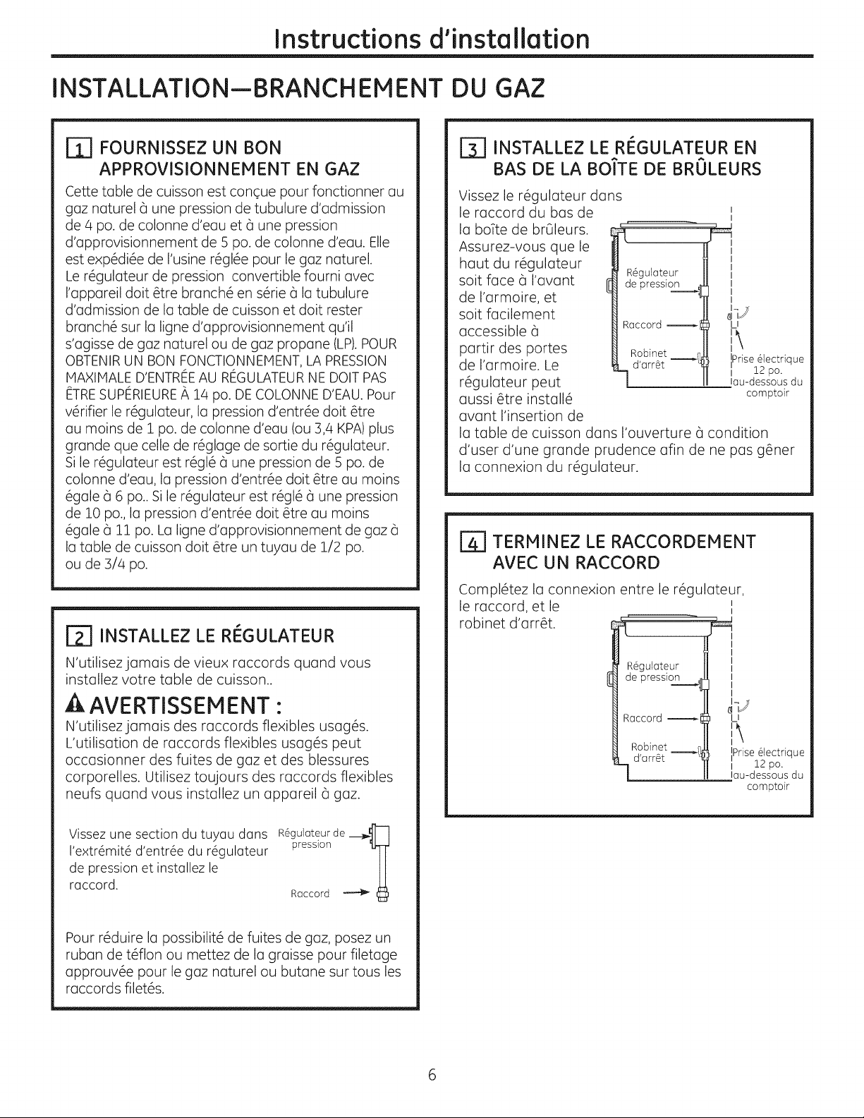
r_ FOURNISSEZ UN BON
APPROVISIONNEMENT EN GAZ
Cette table de cuisson est conque pour fonctionner au
gaz naturel 6 une pression de tubulure d'admission
de 4 po. de colonne d'eau et 8 une pression
d'approvisionnement de 5 po. de colonne d'eau. Elle
est exp6di6e de I'usine r6gl6e pour le gaz naturel.
Le r6gulateur de pression convertible fourni avec
I'appareil doit @re branch6 en s6rie 6 la tubulure
d'admission de la table de cuisson et doit rester
branch6 sur la ligne d'approvisionnement qu'il
s'agisse de gaz naturel ou de gaz propane (LP).POUR
OBTENIR UN BaN FONCTIONNEMENT, LA PRESSION
IVlAXIMALED'ENTREEAU REGULATEURNE DOlT PAS
ETRESUPERIEURE/_14 po. DECOLONNE D'EAU. Pour
v@ifier le r6gulateur, la pression d'entr6e doit @re
au mains de I po. de colonne d'eau (ou 3,4 KPA)plus
grande que celle de r6glage de sortie du r6gulateur.
Si le r6gulateur est r6g166 une pression de 5 po. de
colonne d'eau, la pression d'entr6e doit _tre au mains
6gale 8 6 po.. Si le r6gulateur est r6g16 6 une pression
de 10 po., la pression d'entr6e doit @re au mains
6gale 6 11 po. La ligne d'approvisionnement de gaz 8
la table de cuisson doit @re un tuyau de 1/2 po.
ou de 3/4 po.
[31 INSTALLEZ LE REGULATEUR EN
BAS DE LA BO'[TE DE BRULEURS
Vissez le r6gulateur dans
le raccord du bas de
I
la boTte de brQleurs.
Assurez-vous que le
haut du r6gulateur
soit face 8 I'avant
de I'armoire, et
soit facilement
accessible 6
partir des portes
de I'armoire. Le
r6gulateur peut
aussi _tre install6
R6gulateur
de pression _
Raccord
Robinet _f
d'arr_t "
l]J
U
IPfise @lectrique
I 12 po.
lau-dessous du
comptoir
avant I'insertion de
la table de cuisson dans I'ouverture 6 condition
d'user d'une grande prudence afin de ne pas g@ner
la connexion du r6gulateur.
_-I TERMINEZ LE RACCORDEMENT
AVEC UN RACCORD
[_ INSTALLEZ LE RE_GULATEUR
N'utilisezjamais de vieux raccords quand vous
installez votre table de cuisson..
A AVERTISSEMENT :
N'utilisezjamais des raccords flexibles usag6s.
L'utilisation de raccords flexibles usag6s peut
occasionner des fuites de gaz et des blessures
corporelles. Utilisez toujours des raccords flexibles
neufs quand vous installez un appareil 8 gaz.
Vissez une section du tuyau dans R6gulateur de__._J]
I'extr_mit6 d'entr6e du r6gulateur presslon
de pression et installez le
raccord. Raccord
Pour r6duire la possibilit6 de fuites de gaz, posez un
ruban de t6flon ou mettez de la graisse pour filetage
approuv6e pour le gaz naturel ou butane sur tousles
raccords filet6s.
Compl@ez la connexion entre le r6gulateur,
le raccord, et le
robinet d'arr@t.
R6gulateur
de pression
Raccord
Robinet _I
d'arr_t
m4
i J
I
I
LI
i\
IiPrise61ectrique
I 12 po.
lau-dessous du
comptoir
Page 23

Instructions d'installation
r57 VERIFIEZ QU'IL N'Y A PAS DE
FUITE
LA VITRIFICATIONDE FUITESSUR L'APPAREILDOlT
I_TREEFFECTUCEEN CONFORMITI_AVEC LES
INSTRUCTIONSDU FABRICANT.
Avant de v6rifier qu'il n'y a pas de fuite, assurez-
vous que tous les boutons de brQleurs soient en
position OFF (arr_t).
Apr_s avoir branch6 la table de cuisson au gaz,
v6rifiez qu'il n'y a pas de fuite dans le syst@me
6 I'aide d'un manom@tre.Si vous n'avez pas de
manom@tre,ouvrez I'approvisionnement de gaz 6
la table de cuisson et utilisez un d@ecteur de fuite
liquide 6 tous les raccords etjoints pour trouver les
fuites.
Resserrez tous les raccords le cas 6ch6ant pour
arr@ter les fuites de gaz de la table de cuisson ou
de la ligne d'approvisionnement.
N'UTILISEZ JAMAIS DE FLAMME POUR
VI_RIFIER LES FUITES!
D6branchez la table de cuisson et son robinet
d'arr_t du syst_me de tuyau d'alimentation en gaz
avant de proc6der 6 un essai de pression de ce
syst_me 6 des pressions de test sup@ieures 6 1/2
psig (3,5 kPa).
j_] INSTALLATION SUR UN FOUR
ENCASTRE
Consultez I'installation du four encastr6 pour y
trouver les instructions d'installation.
1
T
_U _ s po. depuis le comptoir
| / _ jusqu'aucentre dutrou
_j. _ de2po.
_-_ Trou de 2 po. (20 7/8 po.
_ deI'avantducomptoir
CSt6s de
I'armoire .... __ _--_.
Vue depuis I'avant de la table de cuisson
_ jusqu'au centre du trou)
Ilsolez la table de cuisson du syst_me de tuyau
d'alimentation en gaz avant de proc6der 6 un essai
de pression du syst_me d'alimentation en gaz 6
des pressions de test 6gales ou inf6rieures 6 1/2
psig (3,5 kPa).
Page 24

Instructions d'installation
INSTALLATION--RACCORDS ELECTRIQUES
AVERTISSEMENT - D6brancheztout
courant61ectriqueau niveaudu disjoncteurde la
maison ou de la boTte5 fusiblesavant d'installer.
ALIMENTATION ELECTRIQUE ET PRISE
Vous devez utiliser une bonne alimentation
61ectrique et une bonne prise pour faire fonctionner
les 616ments 61ectriques de votre table de cuisson.
D
Le cordon d'alimentation de votre appareil est
muni d'une fiche (_trois broches (avec mise 5
la terre) qui doit 6tre utilis6e dans une prise
61ectrique bien mise (_la terre, qui alimente
en courant m6nager CA normal de
120 volts, 60 cycles.
r_
Si vous n'avez pas de prise triphas6e,
demandez 8 un 61ectricien qualifi6 de changer
votre ancienne prise. EN AUCUN CAS, VOUS
NE DEVEZ COUPER NI ENLEVERLA TROISII_ME
BROCHE (TERRE)DU CORDON
D'ALIMENTATION. N'UTILISEZ PAS UN
ADAPTATEUR. N'UTILISEZ PAS UNE RALLONGE.
Assurez une bonne
L mise 51aterre etun
bon contactavant
I'usage
Page 25
Instructions d'installation
BROLEURS DE LA TABLE DE CUISSON
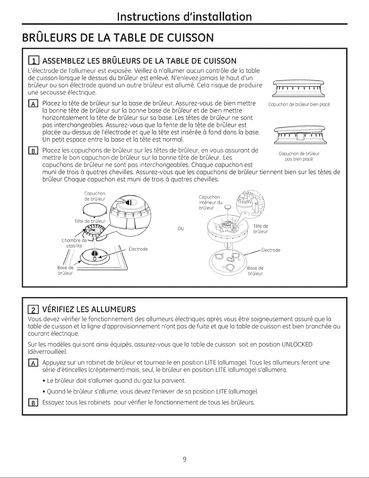
I_] ASSEMBLEZ LES BRULEURS DE LA TABLE DE CUISSON
L'61ectrode de I'allumeur est expos6e. Veillez 5 n'allumer aucun contr61e de la table
de cuisson Iorsque le dessus du brOleur est enlev6. N'enlevezjamais le haut d'un
brOleur ou son 61ectrode quand un autre brOleur est allure6. Cela risque de produire
une secousse 61ectrique.
Placezlat@tede br_leur sur la base de br_leur. Assurez-vous de bien mettre
D
la bonne t@tede br_leur sur la bonne base de br_leur et de bien mettre
horizontalement la t@tede br_leur sur sa base. Lest@tesde br_leur ne sont
pas interchangeables. Assurez-vous que la fente de la t@tede br_leur est
plac6e au-dessus de 1'61ectrodeet que la t@teest ins6r6e 5 fond dans la base.
Un petit espace entre la base et la t@teest normal.
D
Placez les capuchons de brOleur sur les t_tes de brOleur, en vous assurant de
mettre le bon capuchon de brQleur sur la bonne t@te de brOleur. Les pasbienplac6
capuchons de brQleur ne sont pas interchangeables. Chaque capuchon est
muni de trois 5 quatres chevilles. Assurez-vous que les capuchons de brQleur tiennent bien sur les t_tes de
brQleur Chaque capuchon est muni de trois 5 quatres chevilles.
Capuchon de brOleurbien plac6
Capuchon de brQleur
Capuchon
OU
stabilit@ Electrode
Base de \ de
brOleur brOleur
T_te de
brOleur
r_ VI_RIFIEZ LES ALLUMEURS
Vous devez v6rifier le fonctionnement des allumeurs 61ectriques apr@svous @tresoigneusement assur6 que la
table de cuisson et la ligne d'approvisionnement n'ont pas de fuite et que la table de cuisson est bien branch6e au
courant 61ectrique.
Sur les mod61es qui sont ainsi 6quip6s, assurez-vous que la table de cuisson soit en position UNLOCKED
(d6verrouill6e).
EA1 Appuyez sur un robinet de brOleur et tournez-le en position LITE(allumage). Tousles allumeurs feront une
s6rie d'@tincelles (cr6pitement) mais, seul, le brQleur en position LITE(allumage) s'allumera.
. Le brOleur doit s'allumer quand du gaz lui parvient.
, ©uand le br@leurs'allume,vous devez I'enlever de sa position LITE(allumage).
r_ Essayeztousles robinets pour v@ifier lefonctionnement de tousles br_leurs.
Page 26
Instructions d'installation
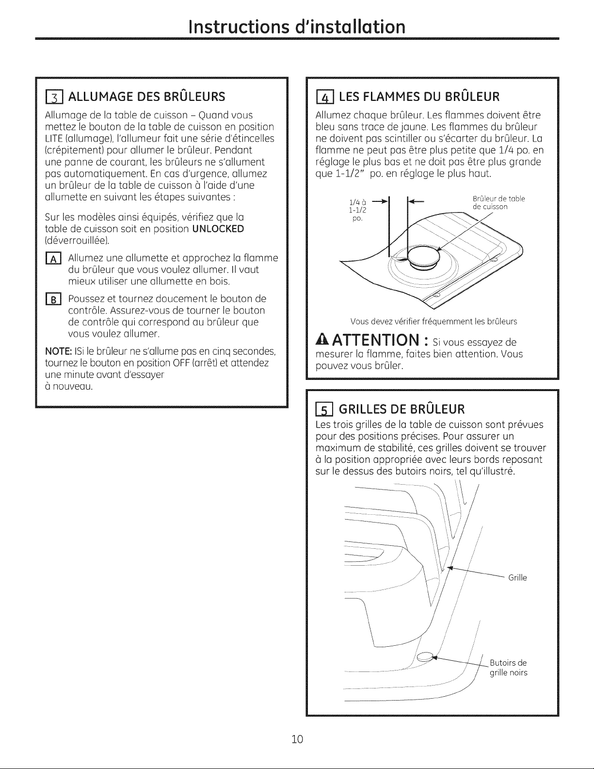
[_] ALLUMAGE DES BRULEURS
Allumage de la table de cuisson- Quand vous
mettez le bouton de la table de cuisson en position
LITE(allumage), I'allumeur fait une s6rie d'6tincelles
(cr6pitement) pour allumer le brGleur. Pendant
une panne de courant, les brGleurs ne s'allument
pas automatiquement. En cas d'urgence, allumez
un brGleur de la table de cuisson _ I'aide d'une
allumette en suivant les 6tapes suivantes :
Sur les modules ainsi @quip6s, v6rifiez que la
table de cuisson salt en position UNLOCKED
(d6verrouill6e).
rA] Allumez une ullumette et upprochez la flamme
du brOleur que vous voulez allumer. IIvaut
mieux utiliser une allumette en bois.
Poussez et tournez doucement le bouton de
Fa
contr61e. Assurez-vous de tourner le bouton
de contr61e qui correspond au br01eur que
vous voulez allumer.
NOTE: ISile brOleur ne s'allume pas en cinq secondes,
tournez le bouton en position OFF (arr_t) et attendez
une minute avant d'essayer
nouveau.
[_ LES FLAMMES DU BRULEUR
Allumez chaque brOleur. Les flammes doivent @tre
bleu sans trace de jaune. Les flammes du brQleur
ne doivent pas scintiller ou s'6carter du br01eur. La
flamme ne peut pas _tre plus petite que 1/4 po. en
r6glage le plus bas et ne dolt pas _tre plus grande
que 1-1/2" po. en r6glage le plus haut.
BrQleur de table
de cuisson
Vous devez v_rifier fr_quemment les brGleurs
A ATTENTION : sivousessayezde
mesurer la flamme, faites bien attention. Vous
pouvez vous brOler.
GRILLES DE BRULEUR
Les trois grilles de la table de cuisson sont pr6vues
pour des positions pr6cises. Pour assurer un
maximum de stabilit6, ces grilles doivent se trouver
(_Io position oppropri6e ovec leurs bards reposant
sur le dessus des butoirs noirs, tel qu'illustr6.
/'
/,
/
/
//
Grille
/ /
/
/
/' /
/
/
/
ji otoir e
...................... _...................... grille noirs
10
Page 27
Instructions d'installation
LISTE DE V(--RIFICATION DE FONCTIONNEMENT
rA1 Assurez-vous que tousles contr61es restent en FI
position OFF (arr#t). V#rifiez que la table
de cuisson soit en position UNLOCKED
(d#verrouill#e) (sur les modules ainsi #quip#s).
Assurez-vous que la circulation d'air autour de la
table de cuisson ne salt pas g6n#e.
Lo plaque min6ralogique de votre table de
cuisson est situ6e en bas de la bo?te de brOleurs.
En plus des num6ros de module et de s#rie, elle
indique la cote des brQleurs, et la cat#gorie de
carburant et la pression de votre table de
cuisson au d6part de la fabrique.
B]
q)uand vous commandez des pi6ces, indiquez
toujours le num@o de s6rie, le num@o de
module et les lettres de code pour obtenir les
bonnes pi6ces de rechange.
Re-v_rification :
V6rifiez 6 nouveau pour vous assurer d'avoir
bien suivi toutes les instructions de ce guide.
Cela assure une bonne utilisation s6curitaire de
la table de cuisson.
11
Page 28
Instructions d'installation
CONVERSION AU GAZ PROPANE (LP)
RENSEIGNEMENTS RELATIFS A LA
[i]
SE_CURITEEQUE VOUS DEVEZ
CONNA'[TRE
Lesdiaphragmes du r6gulateur de pression et du
brQleur sont r6gl6s pour le gaz naturel. Pour utiliser du
gaz propane (LP),vous devez convertir les diaphragmes
du r6gulateur de pression et du br01eur. Lesorifices
des 616ments de gaz PLdes br01eursde la surface de
cuisson sont rattach6s aux r6gulateur de pression et
accompagn6s des instructions de conversion du gaz PL.
A ATTENTION :Latabledecuisson,ou
d6part de I'usine, est r6gl6e pour le goz noturel. Si
vous d6sirez utiliser votre table de cuisson avec du
goz en bouteille (LP),vous devez d'obord remplocer les
diaphragmes, puis convertir le r6gulateur de pression.
[]
B]
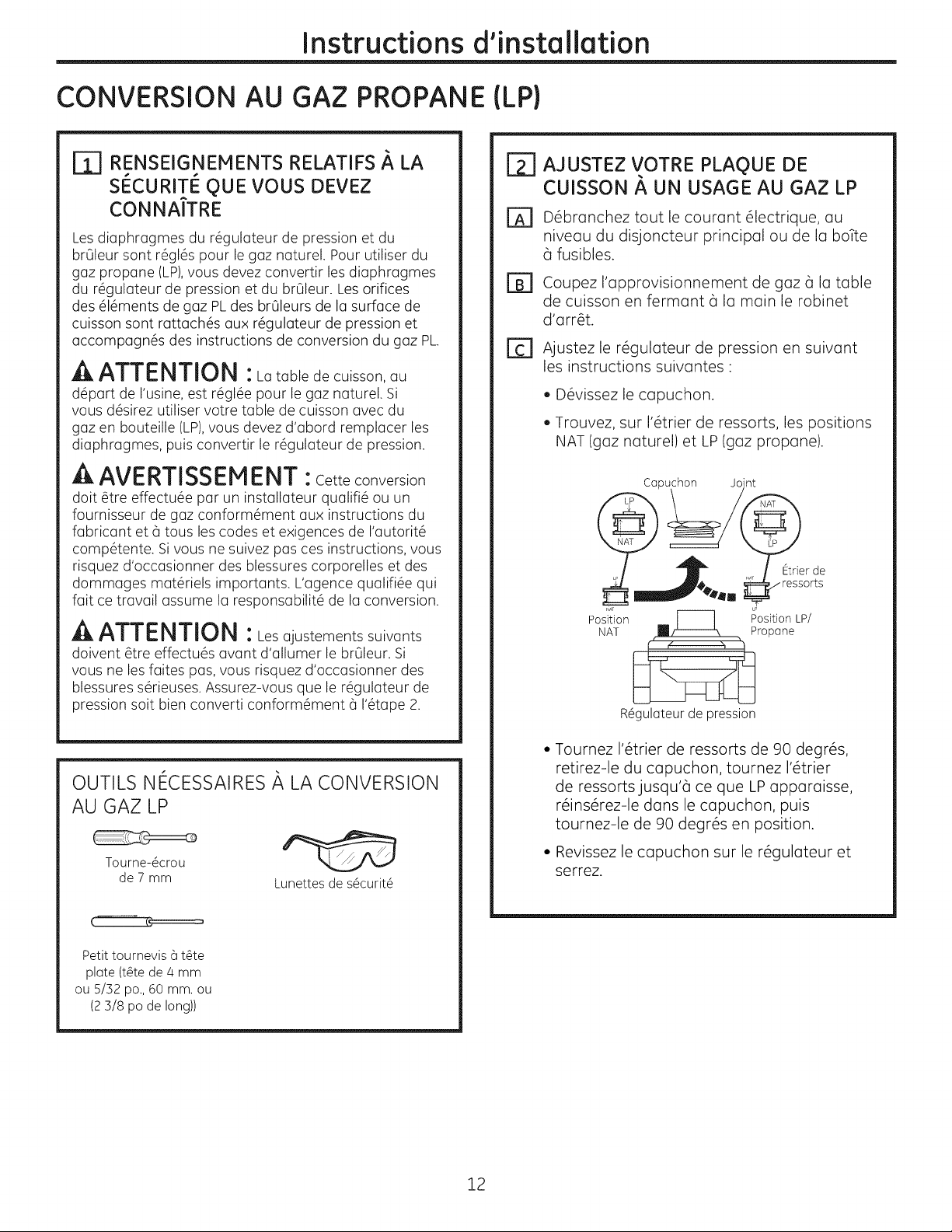
r_ Ajustez le r6gulateur de pression en suivant
AJUSTEZ VOTRE PLAQUE DE
CUISSON #, UN USAGE AU GAZ LP
D6bronchez tout le courant 61ectrique, au
niveau du disjoncteur principal ou de la boTte
6 fusibles.
Coupez I'approvisionnement de gaz 6 la table
de cuisson en fermant 6 la main le robinet
d'arr_t.
les instructions suivantes "
, D6vissez le capuchon.
. Trouvez, sur I'@trier de ressorts, les positions
NAT (gaz naturel) et LP (gaz propane).
A AVERTISSEMENT :Cetteconversion
dolt@ireeffectu6epar un instolloteurquolifi6ou un
fournisseurde goz conform6ment ou× instructionsdu
fobricontet6 touslescodes et exigences de l'outorit6
comp6tente. Sivous ne suivezpos ces instructions,vous
risquezd'occosionnerdes blessurescorporelleset des
dommoges mot6rielsimportonts.L'ogencequolifi6equi
fairce travailassume Ioresponsobilit6de Ioconversion.
A ATTENTION : Lesojustements suivonts
doivent@treeffectu@sovont d'allumerlebrOleur.Si
vous ne lesfoitespos,vous risquezd'occosionnerdes
blessuress6rieuses.Assurez-vous que ler6guloteurde
pressionsaltbienconverticonform6ment 6 l'6tope2.
OUTILS Nt_CESSAIRESA LA CONVERSION
AU GAZ LP
Tourne-@crou
de 7 mm
Lunettes de s@curit@
Copuchon Joint
1_1!_4,mt111 ! ,._/ Etrierde
Position r----] Position LP/
NAT [] _ Propane
R_guloteur de pression
• Tournez 1'6trier de ressorts de 90 degr6s,
retirez-le du capuchon, tournez 1'6trier
de ressorts jusqu'6 ce que LP apparaisse,
r6ins6rez-le dons le capuchon, puis
tournez-le de 90 degr6s en position.
• Revissez le capuchon sur le r6gulateur et
serrez.
_ ressorts
Petit tournevis 6 t@te
plate (t@tede 4 mm
ou 5/32 po., 60 mm. ou
(2 3/8 po de long))
12
Page 29
Instructions d'installation
CONVERSION AU GAZ PROPANE (LP)(SUITE)
[_ CHANGEZ LES DIAPHRAGMES DES
BRULEURSDE LA TABLE DE CUISSON
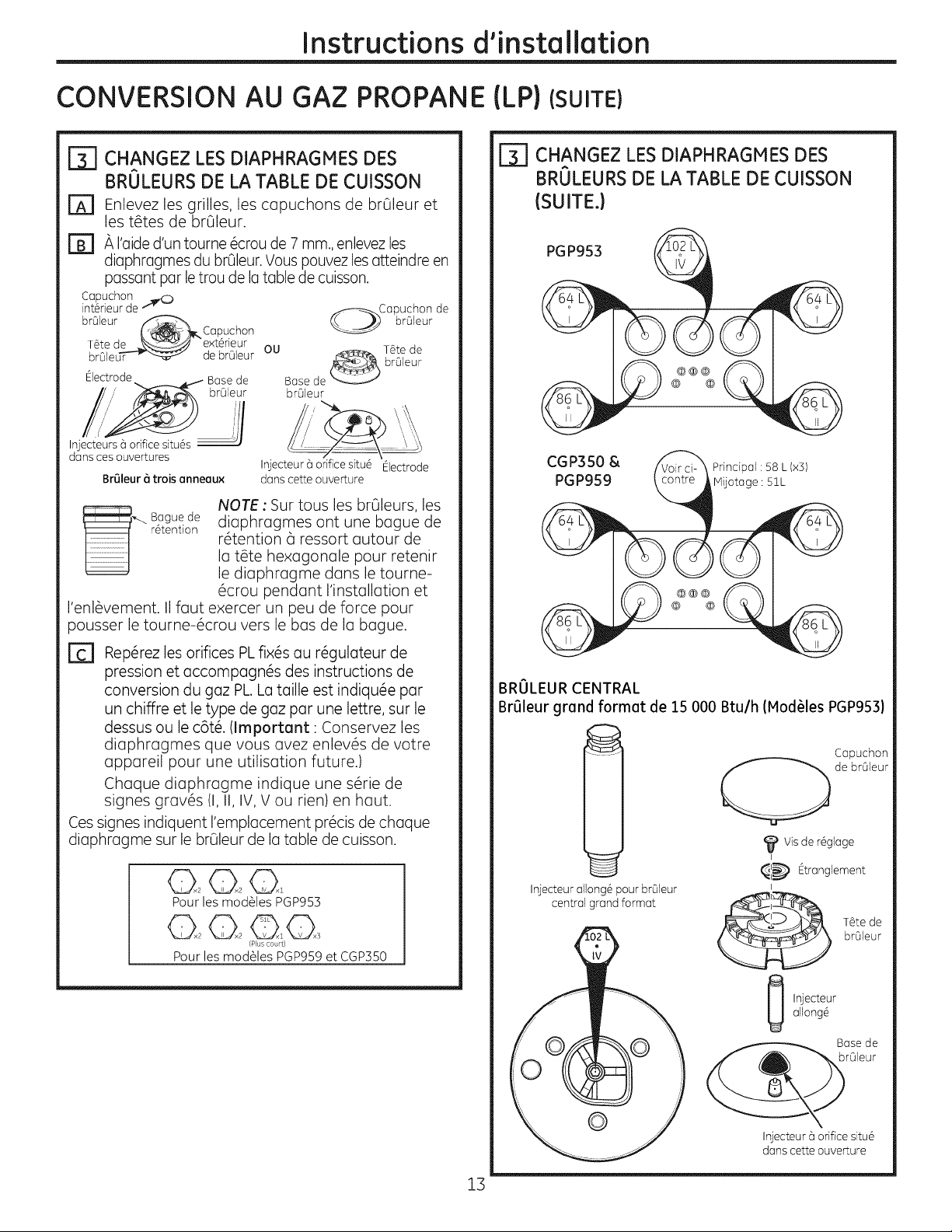
[] Enlevez les grilles, les capuchons de brOleur et
les t_tes de br01eur.
[] A I'aided'un tourne @croude7 ram.,enlevez les
diaphragmes du br01eur.Vous pouvez lesatteindre en
passant par letrou de latable de cuisson.
Copuchon .._,(_
int#rieur de
brQleur
T_te de "_,_ e×t#rieur
brQleu_ de brQleur OU
Electrode-._ _ Bose de Bose de
dons ces ouvertures
_,_. Boguede NOTE : Sur tousles brQleurs, les
,_ _ Copuchon
/" brQleur brQleur
BrQleur _ trois anneau× dons cette ouverture
r6tention diaphragmes ont une bague de
Injecteur 6 orifice situ# Electrode
la t_te hexagonale pour retenir
r#tention (_ressort autour de
le diaphragme dans le tourne-
#crou pendant I'installation et
I'enl_vement. II faut exercer un peu de force pour
pousser le tourne-6crou vers le bas de la bague.
Copuchon de
brQleur
T#te de
brQleur
[-_ CHANGEZ LESDIAPHRAGMES DES
BRULEURSDE LA TABLE DE CUISSON
(SUITE}
PGP953
CGP350 &
PGP959
Principal: 58 L (×])
MUotage : 51L
[] Rep#rez les orifices PLfixes au r#gulateur de
pression et accompagn#s des instructions de
conversion du gaz PL La taille est indiqu#e par
un chiffre et le type de gaz par une lettre, sur le
dessus ou le c6t#. (Important : Conservez les
diaphragmes que vous avez enlev6s de votre
appareil pour une utilisation future.}
Chaque diaphragme indique une s#rie de
signes grav#s (I, II, IV, V ou rien) en haut.
Ces signes indiquent I'emplacement pr#cis de chaque
diaphragme sur le brQleur de la table de cuisson.
020201
Pour les modules PGP953
/Pus court}
Pour lesmodules PGP959et CGP]50
BRULEUR CENTRAL
BrQleur grand format de 15 000 Btu/h (ModUles PGP953}
Capuchon
de brQleur
Visde r#gloge
I
_'_ Etronglement
Injecteur ollong6 pour brQleur
central grand formot
I
allong6
Injecteur
brOleur
Bosede
rOleur
Injecteur 6 orificesitu#
dons cette ouverture
1]
Page 30

Instructions d'installation
CHANGEZ LES DIAPHRAGHES DES
BROLEURS DE LA TABLE DE
CUISSON (SUITE}
BROLEUR CENTRAL
Br_leur 6 trois anneaux de 20 000 Btu/h (ModUles
PGP959 et CGP350)
Injecteurs 5orifice
situ6sdans ces
Orifice principal
Orifice principal
[_ CHANGEZ LES DIAPHRAGHES DES
BRULEURS DE LA TABLE DE
CUISSON (SUITE}
BROLEUR AVANT GAUCHE
(ModUles PGP959 et CGP350)
Vis de plaque
Surla visde plaque
figure un N pour
guz naturel et un L
pour goz de p6trole
liqu6fi6.
Orifice principal
NOTA - L'orifice principal est situ6 au centre du
brOleur, tandis que Io vis de plaque est situ6e 5 la
droite du centre du brOleur.
Orifice de mijotug,
(Plus court)
Orifice principal
D
Installez les orifices de gaz LP (propane) et la
vis de plaque (sur les modules PGP959et
CGP350seulement) 5 leur emplacement
pr6cis tel qu'indiqu6 dans les illustrations
pr6c6dentes.
[E]
Remettez les diaphragmes pour gaz naturel
sur le support et fixez 5 nouveau le support et
la feuille d'instructions au r6gulateur de
pression 5 I'aide de la vis enlev6e
pr6c6demment.
r_l Remettez en place les t@tes, les capuchons de
brQleur et les grilles.
14
Page 31
Instructions d'installation
CONVERSION AU GAZ PROPANE (LP)(SUITE)
AJUSTEZ LES FLAMMES DES
BROLEURS
Allumez tousles br01eurs au maximum et
[]
v6rifiez les flammes. Elles doivent @tre bleu
avec un peu de jaune 6 leur extr6mit6. Des
particules 6trang@res dans la ligne de gaz
peuvent occasionner une flamme orange au
d6but, mais cette couleur dolt disparaTtre
rapidement.
Tournez le bouton du brQleur de la table de
[]
cuisson 6 son r6glage le plus bas tout en
observant la flamme.
Ajustez le r@glage de flamme basse 6 I'aide de la vis
de d6rivation de robinet comme suit
Vous devez ajuster le r6glage de flamme basse
avec deux autres brQleurs en fonctionnement
en r6glage moyen. Cela vous emp@che de r6gler
trop bas la flamme basse, et qui risque d'@eindre
la flamme quand d'autres brOleurs sont en
fonctionnement.
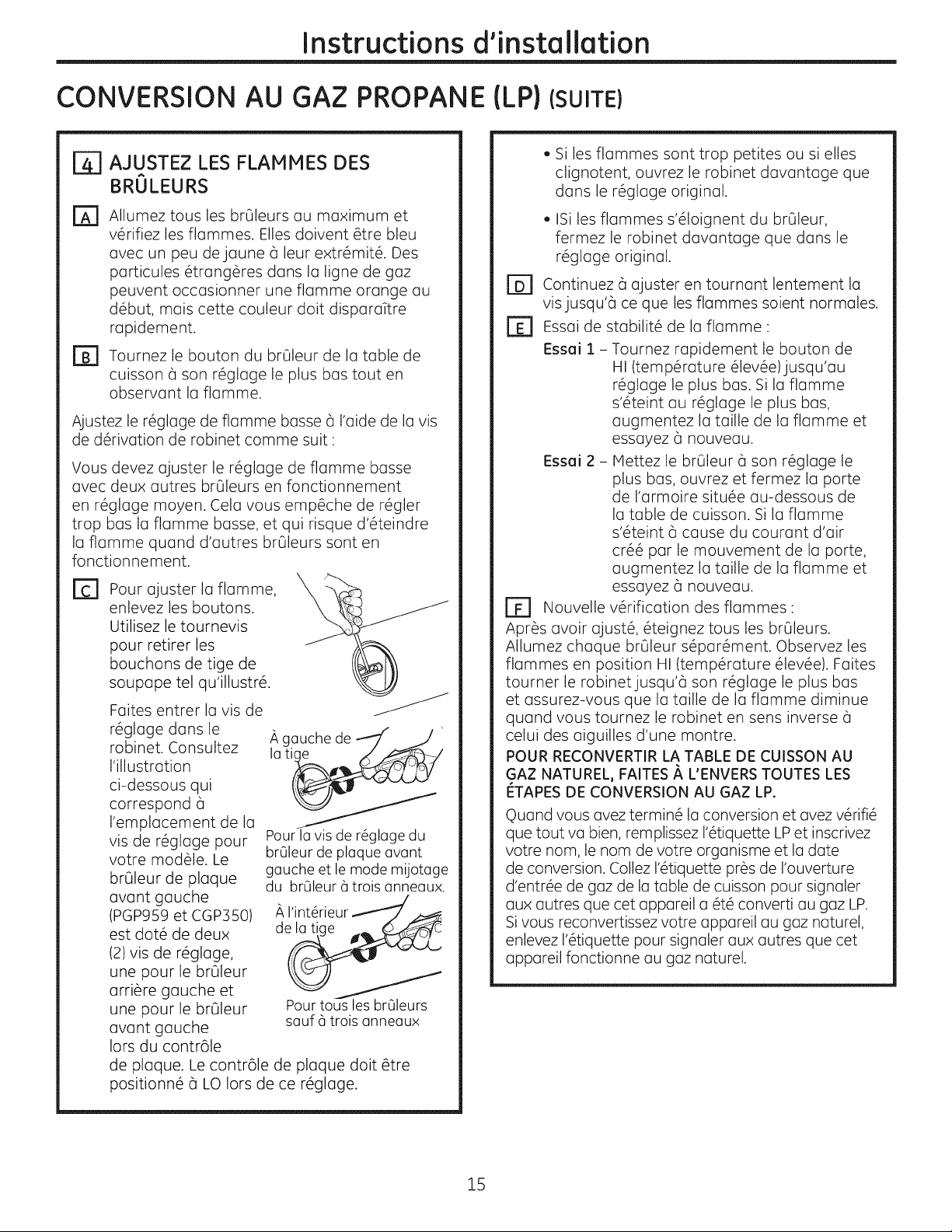
[] Pour ajuster la flamme, X _"_
enlevez les boutons.
Utilisez le tournevis
pour retirer les
bouchons de tige de
soupape tel qu'illustr6.
Faites entrer la vis de J
r6glage dans le A gauche de
robinet. Consultez lati
I'illustration
ci-dessous qui
correspond 6
I'emplacement de la
vis de r6glage pour pour la vis de r6glage du
votre mod@le. Le brOleur de plaque avant
brOleur de plaque gauche et le mode mijotage
avant gauche
(PGP959 et CGP350)
est dot6 de deux de la
(2) vis de r#glage,
une pour le br01eur
arri6re gauche et
une pour le brQleur Pour tousles brOleurs
avant gauche sauf 6 trois anneaux
Iors du contr61e
de plaque. Le contr61e de plaque dolt @tre
positionn6 6 LO Iors de ce r6glage.
du brOleur 6trois anneaux.
. Si les flammes sont trop petites ou si elles
clignotent, ouvrez le robinet davantage que
dans le r6glage original.
. ISi les flammes s'61oignent du br01eur,
fermez le robinet davantage que dans le
r6glage original.
rD] Continuez 6 ajuster en tournant lentement la
visjusqu'a ce que les flammes soient normales.
Essai de stabilit6 de la flamme "
Essai 1 - Tournez rapidement le bouton de
HI (temp6rature 61ev6e)jusqu'au
r6glage le plus bas. Si la flamme
s'6teint au r6glage le plus bas,
augmentez la taille de la flamme et
essayez 6 nouveau.
Essai 2- Mettez le br01eur 6 son r6glage le
plus bas, ouvrez et fermez la porte
de I'armoire situ6e au-dessous de
la table de cuisson. Si la fiamme
s'6teint 6 cause du courant d'air
cr66 par le mouvement de la porte,
augmentez la taille de la flamme et
essayez 6 nouveau.
r_ Nouvelle v@ification des flammes:
Apr_s avoir ajust6, @eignez tousles brOleurs.
Allumez chaque br01eur s6par6ment. Observez les
flammes en position HI (temp@ature 61ev6e). Faites
tourner le robinetjusqu'6 son r6glage le plus bas
et assurez-vous que la taille de la fiamme diminue
quand vous tournez le robinet en sens inverse 6
celui des aiguilles d'une montre.
POUR RECONVERTIR LA TABLE DE CUISSON AU
GAZ NATUREL, FAITES _, L'ENVERS TOUTES LES
I_TAPES DE CONVERSION AU GAZ LP.
©uand vous avez termin6 la conversion et avez v6rifi6
que tout va bien, remplissezI'@iquette LPet inscrivez
votre nom, le nom de votre organisme et la date
de conversion. CollezI'@iquette pr@sde rouverture
d'entr@ de gaz de latable de cuisson pour signaler
aux autres que cet appareil a 6t6 converti au gaz LP.
Sivous reconvertissezvotre appareil au gaz naturel,
enlevezI'@iquettepour signaler aux autres que cet
appareil fonctionne au gaz naturel.
15
Page 32

Notes.
16
Page 33

I struccio es
Estufa a GasSellada de 30°'
del stal ci"
j r_Preguntas? Llame a 800.GE.CARES (800.432.2737) o visite nuestro sitio web en: GEAppliances.com
"---" En Canadd, Ilame al 1.800.561.3344 o visite nuestro sitio web en: www.geapplionces.ca
EN EL COMMONWEALTH DE
MASSACH USETTS:
, Este producto debe ser instalado par un plomero
licenciado o un meccinico gasista.
, AI usar v61vulas de cierre de gas tipo bal6n,
deber6n ser del tipo de manila T.
, Cuando se use un conector de gas flexible, 6ste
no deberci exceder los 3 pies.
ANTES DE COMENZAR
Lea estas instrucciones en su totalidad y
atentamente.
.IMPORTANTE - Conserveestas
instrucciones para usa del inspector local.
PGP953, PGP959, CGP350
PARA SU SEGURIDAD:
_ADVERTENCIA - silainformaci6n
de este manual no se sigue exactamente, se
podr6 producir un incendio, explosi6n o p_rdida
de gas, ocasionando daSos sabre la propiedad,
lesiones o la muerte.
No guarde ni use gasolina u otros vapores
inflamablesy Iiquidos cerca de _ste ni de otros
electrodom6sticos.
No instale este producto con una campana con
cortina de aire u otra campana de cocina que Ileve
aire a la placa de cocci6n. El flujo de aire podr6
interferir en el funcionamiento de los quemadores
de gas, produciendo riesgos de incendio o explosi6n.
QUE DEBE HACER Sl HUELE
GAS:
• IMPORTANTE -Cumplacontodoslos
c6digos y ordenanzas gubernamentales.
, Nota para el Instalador - AsegOrese de que el
Comprador conserve estas instrucciones
, Nota para el Comprador- Conserve estas
instrucciones para referencia futura.
, Si se producen fallas en el producto debido a una
instalaci6n inadecuada, la Garantia no cubrir6
las mismas.
_,ADVERTENCIA - Este
electrodom6stico deberci estar conectado a tierra
de forma adecuada.
.IMPORTANTE - Uaprueba de goteras
del electrodom6stico se deberci realizar de
acuerdo con las instrucciones del fabricante.
, La instalaci6n correcta es responsabilidad del
instalador y cualquier falla del producto debido a
una instalaci6n inadecuada NO estar6 cubierta
par la garantia.
IkADVERTENCIA - Desconectetodas
las fuentes el6ctricas del disyuntor principal o de la
caja de fusibles antes de realizar la instalaci6n.
, No intente iluminar ning6n electrodom_stico.
No toque ning6n interruptor el_ctrico; no use
tel_fonos en su edificio.
, De inmediato llame a su proveedor de gas
desde el tel_fono de un vecino. Siga las
instrucciones del proveedor de gas.
, Si no se puede comunicar con su proveedor de
gas, flame al departamento de bomberos.
La instalaci6n y las reparaciones deber6n ser
realizadas par un instalador calificado, agencia
de servicios o el proveedor de gas.
Esta estufa estc_certificada por UL. En el Manual
del Propietario, encontrarc_ precauciones de
seguridad. Lea las mismas detenidamente.
. Esta estufa se deber6 instalar de acuerdo con
los c6digos locales, o en la ausencia de c6digos
locales, con el C6digo de Gas Combustible
Nacional, ANSIZ223.1/NFPA.54, t]ltima edici6n.
, AsegQreseque su cocina sea instalada de forma
adecuada por un instalador calificado o t6cnico
del servicio.
, Para que no se alcancen los quemadores de
la superficie, se deber6 evitar la colocaci6n de
gabinetes sobre los quemadores.
, No instale la unidad cerca de la puerta exterior o
donde una corriente pueda afectar su uso.
i
31-i0858-1 (08-12GE) 1
Page 34
Instruccionesde Instalaci6n
INSTRUCCIONES IMPORTANTES DE SEGURIDAD
REOUISITOS ELI_CTRICOS
Este electrodom6stico deber6 ser suministrado
con la frecuencia y el voltaje adecuados, y set
conectado a un circuito derivado individual
correctamente conectado a tierra, protegido por un
disyuntor o fusible con el amperaje que figura en la
etiqueta de caracterfsticas t6cnicas.
Lerecomendamos que el cable el6ctrico y el
gancho de su estufa sean conectados pot un
electricista calificado. Luego de la instalaci6n, pida
al electricista que le muestre d6nde se encuentra la
desconexi6n principal de su estufa.
Consulte a los servicios locales sobre qu6 c6digos
el6ctricos se aplican en su 6tea. Si el cable de su
estufa no es adecuado de acuerdo con los c6digos
del gobierno, se podr6 producir una condici6n
riesgosa. En caso de no haber c6digos, el cable
y el fusible de su estufa deber6n cumplir con los
requisitos del C6digo Nacional de Electricidad,
ANSI/NFPA No. 70--Oltima edici6n. Puede solicitar
una copia escribiendo a:
National Fire Protection Association
Batterymarch Park
Ouincy, HA 02269
En Canad6, el cable y el fusible de su estufa
deber6n cumplir con los requisitos del C6digo de
Electricidad de Canad6.
AsegOrese de que la instalaci6n de este producto
en una casa m6vil cumpla con el Est6ndar
de Construcci6n y Seguridad de una Casa
Manufacturada, Titulo 24 CFR, Parte 3280. Si
este est6ndar no se aplica, deber6 cumplir
con el est6ndar de Instalaciones de Casas
Manufacturadas, ANSI/VCSBS A225.1, o con los
c6digos locales donde se apliquen. Puede solicitar
una copia del Est6ndar Federal escribiendo a:
Office of Mobile Home Standards
HUD Building
4517th Street, S.W.
Washington, D.C. 24010
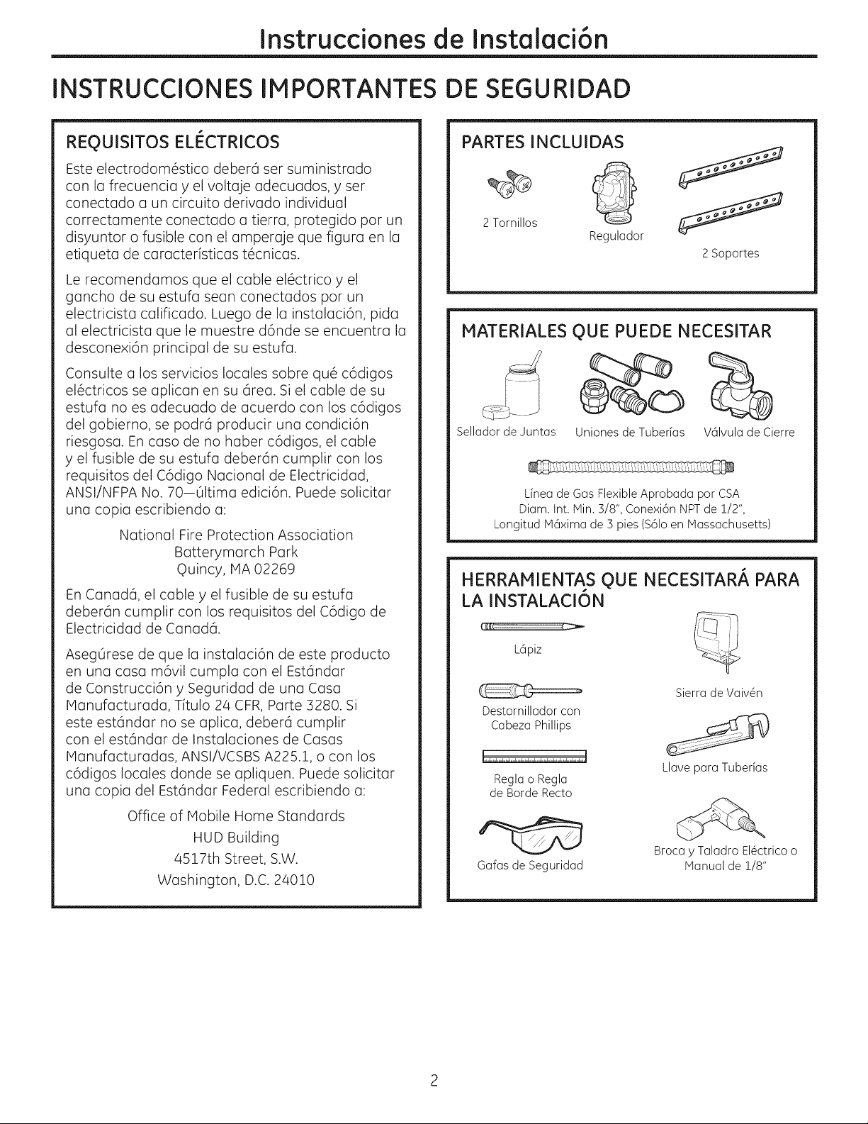
PARTES INCLUIDAS
2 Tornillos Regulador
2 Soportes
MATERIALES QUE PUEDE NECESITAR
Sellador de Juntas Uniones de Tuberfas V61vulade Cierre
L[nea de Gas Flexible Aprobada por CSA
Diam. Int. Min. 3/8", Conexi6n NPTde 1/2",
Longitud M6xima de 3 pies ($61oen Massachusetts)
HERRAMIENTAS OUE NECESITAR/_ PARA
LA INSTALACI6N
L6piz
Sierra de Vaiv@n
Destornillador con
Cabeza Phillips
Regla o Regla
de Borde Recto
Gafas de Seguridad
Llave para Tuberias
Broca y Taladro El@ctricoo
Manual de 1/8"
Page 35

Instruccionesde Instalaci6n
J
LISTA DE CONTROL DE PRE-INSTALACION
AI preparar la abertura de la estufa,
r_
asegOrese de que el interior del gabinete y
de la estufa no interfieran uno con otto.
(Consulte la secci6n sobre preparaci6n de la
abertura).
Retire los materiales de embalaje, cajas de
@
parrillas, regulador con instrucciones, y el
paquete de instrucciones de la estufa antes
de realizar la instalaci6n.
rcl Retire las instrucciones de instalaci6n del
paquete de instrucciones y lea las mismas
de forma detenida antes de comenzar.
AsegOrese de colocar las instrucciones
(Hanual del Propietario, Instrucciones de
Instalaci6n, etc.) en un lugar seguro para
referencia futura.
_-------_ Paquete de Instrucciones
izi
Cajas con las
//
//
AsegOrese de contar con todas las
r61
herramientas y materiales necesarios antes
de comenzar con la instalaci6n de la estufa.
Su hogar deber6 brindar el servicio el#ctrico
B]
necesario para un uso seguro y apropiado
de su estufa. (Consulte la secci6n sobre
requisitos el#ctricos}.
AI instalar la estufa en su hogar, asegOrese
D
de que todos los c6digos y ordenanzas
locales se sigan exactamente como se
indica.
Aseg0rese de que los cobertores de pared,
[]
mesada y gabinetes alrededor de la estufa
puedan resistir el color (basra 200° F)
generado por la estufa.
Page 36

Instruccionesde Instalaci6n
J
PREPARACION DE LA ABERTURA
rT] MANTENGA LAS SIGUIENTES
DIMENSIONES MINIMAS DE DESPEJE
13" de I
m6×ima debajo R- Despeje minima
de gabinetes desde la apertura
desprotegidos basra la pared del
50" de despeje
mfnimo desde
C- Despeje
mfnimo desde
la apertura
hasta le pared
trasera
L - Despeje mfnimo f-_.
desde la abertura
hasta la pared del Base de
lado izquierdo gabinete de S0"
Mfnimo de 2 1/2" desde la apertura m6s
haste el frente de la mesada
la mesada hasta I 18" de altura
una superfide I desde la
supenor . mesada basra
desprotegida el gabinete m6s
enche
lado derecho
cercano sabre
Jiera de
los lados de la
unidad.
L R C
IPGP953 3-3/4" 6" 2-1/4"
PGP959 12" 12" 2-7/8"
CGP350 12" 12" 2-7/8"
SEDEBERANMANTENERTODOS LOSDESPEJES
HORIZONTALESPaR UN MiNIMa DE 18" SABRE
LA SUPERFICIE DE COCCION.
7/16"
NOTA: Deje un espacio vertical
de par Io menos 7/16" desde
la parte inferior de la placa de
CAJON
cocci6n (o una profundidad de
par Io menos 3-11/16" desde
la mesada) hasta cualquier
superficie combustible, tal
coma el caj6n de un gabinete.
Para lainstalaci6n de la isla,deje un espacio-1 m
minima de 2-W' entre la abertura y el extrem6 frontal y '
trasero de la mesada. Dejeun minima de 3" entre la aberturc
y losextremos laterales de la mesada.
[2] DIMENSIONESTOTALESDE LA ESTUFA
30" __._""_ 21"
[_ UBICACI6N DEL SUMINISTRO DE
GAS RECOMENDADA DESDE LA
PARED TRASERA 1"comaminima,
desde Io Pared Trasera
Ubicaci6n del '_
suministro ._7'_
de gas _ Desde
recomendada/_' la Linea
Central de
Carte
[_] ASEGURESE DE OUE LOS COBERTORES
DE PARED, MESADA V GABINETES
ALREDEDOR DE LA ESTUFA PUEDAN
RESISTIREL CALOR (HASTA 200°F)
GENERADO PaR LA ESTUFA.
Los cobertores
de pared,
gabinetes, y la I
mesada deben
.__resistir un calor i
I.NSTALACI6N PaR DELANTE
UNICAMENTE DE ACUERDO CON
LA LEV DE ESTADOUNIDENSES
CON INCAPACIDADES (ADA)
"_ v 28-1//4"
19-3/8" _-_
DIMENSIONES DE ENCASTRE DE LA
MESADA
Para asegurar la precisi6n, es mejor realizar una
plantilla al cortar la abertura de la mesada.
Deje un espacio J- J
vertical de par Io
menos S"entre
la mesada y la
cubierta.
NOTA: The enclosure must
be made of wood material.
Adem6s, un panel de acceso
es necesario para la toma I]
de corriente, regulador de
L
presi6n, v61vulade cierre, los
soportes de los costados, y el servicio t6cnico.
r
Page 37

Instruccionesde Instalaci6n
J
INSTALACION DE LA UNIDAD DE LA ESTUFA
[i]
UB!OUE ELTOMACORRIENTE
ELECTRICOV LA VALVULA DE CIERRE
DE GAS DEBAJO DEL GABINETE
NUNCA VUELVA A _ L-_
USAR CONECTORES _] ,,_\
ANTIGUOS AL V_lvula '
INSTALAR ESTA Cierre_ i •
UNIDAD. Debajode la
Instale una v61vula de cierre manual en
la tuberia de gas en una ubicaci6n de fdcil acceso
fuera de la estufa. Aseg0rese de saber c6mo y
d6nde cerrar el suministro de gas de la estufa.
Instale el tomacorriente el6ctrico de 12" debajo de
la mesada.
H i
I_e g__ iTomacomente
U
EI6ctricode 12"
Mesada
J]] PROTEJA LA SUPERFICIE DE LA
ESTUFA
Coloque una toalla o mantel sobre la mesada.
Apoye la estufa al rev6s sobre la superficie
protegida.
Parte inferior de la estufa
r_ ADHIERA LOS SOPORTES A LA
ESTUFA
Retire el tornillo del costado de la estufa y atornille
el soporte al costado de la unidad de la estufa.
Repita en el lado opuesto de la estufa.
Marca para
Realizar
Parte Inferior Agujero \
SuF
la Estufa
de la Estufa
\
r_ INSERTE LA ESTUFA EN EL
ENCASTRE
Inserte la estufa centrada sobre la abertura del
encastre. Aseg@ese de qua el extremo frontal de
la mesada est6 paralelo a la estufa. Haga el control
final para verificar qua todos los despejes necesarios
hayan sido realizados.
Tela debajo de la estufa
ITI UBIQUE LAS PARTES DE MONTAJE
Retire los soportes del paquete de instrucciones.
Una vez colocada la unidad, atornille el soporte
sobre los costados del gabinete para asegurar la
unidad en su ubicaci6n.
Page 38

Instruccionesde Instalaci6n
J
INSTALACION -CONEXIONES DE GAS
r_1 BRINDE EL SUMINISTRO DE GAS
ADECUADO
Esta estufa fue diseBada para funcionar con gas
natural con una presi6n de admisi6n de columna
de agua de 5" y una presi6n de suministro de
columna de agua de 7". Se envia con el equipo
de f6brica para gas natural. El regulador de
presi6n convertible suministrado con la unidad
debe set conectado en serie con la admisi6n de
la estufa y deber6 permanecer en serie con la
linea de suministro, sin importar si se est6 usando
gas natural o LP. PARA UN FUNCIONAMIENTO
CORRECTO, LA MAXIMA PRESION DE ENTRADA AL
REGULADOR NO DEBERA SERSUPERIORA 14" DE
PRESION DE LA COLUMNA DE AGUA. Para controlar
el regulador, la presi6n de entrada deber6 set
por Io menos de una columna de agua de 1". (o
3.4 KPA) superior que la configuraci6n de salida
del regulador. Si el regulador est6 configurado
para una presi6n de columna de agua de 5%la
presi6n de entrada deber6 ser por Io menos de
una columna de agua de 6". Si el regulador est6
configurado para una columna de agua de 10", la
presi6n de entrada deber6 ser por Io menos de una
columna de agua de 11". La linea de suministro de
gas a la estufa deber6 ser un tubo de 1,_,,o s4".
ITI INSTALACI6N DEL REGULADOR
NUNCA VUELVA A USAR CONECTORES ANTIGUOS
AL INSTALAR ESTA ESTUFA.
A^r-_i nr- _-1-r- L ,_mA
A:_t'_L;VP-K|t|_L, II'_: Nunca vuelva a usar
conectores fie×ibies viejos. Ei uso de conectores
fie×ibies viejos puede ocasionar goteras y
iesiones personaies. Siempre use conectores
fie×ibies nuevos ai instaiar eiectrodom_sticos a
gas,
Atornille una secci6n de la
tuberia en el extremo de
la entrada del regulador
de presi6n e instale el
acoplador.
de Presi6n
Regulador£
Acoplador
INSTALACI6NDELREGULADORENLA
PARTEINFERIORDELACAJADELOS
QUEMADORES
Atornille el regulador
en la conexi6n de
la tuberia inferior
de la caja de los
quemadores.
Aseg0rese de que
la parte superior
del regulador est6
mirando hacia el
frente del gabinete,
Regulador _1
de Presi6n"--_1
Dlador
V61vula de I
Cierre
U
Ii Tomacorfiente
II EI6ctrico de
I 12"Debajo de
la Mesada
f6cilmente accesible
a trav6s de las puertas del gabinete. El regulador
tambi6n puede ser instalado antes de insertar la
estufa en el encastre si se tiene extremo cuidado
para asegurar que la conexi6n del regulador no
est6 comprometida.
| COMPLETE LA CONE×I6N CON UN
ACOPLADOR
Complete la
conexi6n entre
el regulador, el
acoplador de la
tuberia, y la v61vula
de cierre.
Regulador_
de Presi6n
S,coplador
I
U
i\
V61vula de__._
Cierre
Tomacorriente
El6ctrico de
I 12" Debajo de
la Mesada
A fin de reducir la probabilidad de p@didas de
gas, aplique cinta de Tefl6n o un compuesto de
hilo aprobado para uso con gases LPy Natural en
todas las conexiones roscadas.
Page 39

Instruccionesde Instalaci6n
r_ CONTROLE LAS
ELCONTROL DE PERDIDAS DEL ELECTRODOMESTICO
SE DEBERAREALIZARDE ACUERDO CON LAS
INSTRUCCIONESDEL FABRICANTE
Antes de controlar p@rdidas, asegOrese de que
todas las perillas de los quemadores est@n en la
posici6n OFF(Apagado).
Luego de conectar la estufa al gas, controle
p@didas en el sistema utilizando un man6metro.
Si no dispone de un man6metro, encienda el
suministro de gas a la estufa y use un detector de
p@didas liquido en todas lasjuntas y conexiones
para controlar que no haya p@didas.
De ser necesario, ajuste todas las conexiones a fin
de evitar la p@dida de gas en la estufa o la linea de
suministro.
iNO USE UNA LLAMA ABIERTA PARA
CONTROLAR PI_RDIDAS!
Desconecte la estufa y su v61vula de cierre
individual del sistema de tuberia de suministro
de gas durante una prueba de presi6n de dicho
sistema en presiones de prueba superiores a 1,_
psig (3.5 kPa).
Este electrodom6stico deber6 ser aislado del
sistema de tuberfa de suministro de gas, cerrando
la v61vula de cierre individual durante cualquier
prueba de presi6n del sistema de suministro de gas
con pruebas de presi6n iguales o inferiores a 1/2
Psig (3.4 kPa).
PI_RDIDAS
_] INSTALACI6N SOBRE EL HORNO
INCORPORADO
Para acceder a instrucciones de instalaci6n
completas, consulte la instalaci6n del homo
incorporado.
1
J J_ s,, aJCentro del Agujero
_ Mesada
_ de 2"_e Diam. desde la
Codode900 7 I
Lados del Gabinete _ //_"
Vista desde el Frente de la Estufa
II1_
J
(20 7/8" desde el frente
__.... Agujero de 2" de Diam.
de la Mesada basra el
Centro del Agujero)
Page 40

Instruccionesde Instalaci6n
J J
INSTALACION - CONEXIONES ELECTRICAS
,tkADVERTENCIA - De_co_ectetodas
las fuentes el6ctricas del disyuntor principal o de la
caja de fusibles antes de realizar la instalaci6n.
SUIvlINISTRO V TOIACORRIENTE
ELECTRICO
Se deber6 usar un suministro y tomacorriente
el6ctrico adecuado para utilizar las partes
el6ctricas de su estufa.
El cable de corriente de este electrodom6stico
D
est6 equipado con un enchufe de 3 patas (a
tierra) que se deber6 usar con un
tomacorriente de 3 agujeros correctamente
conectado a tierra con corriente hogare6a
est6ndar de 220 voltios y 60 ciclos de CA.
D
Si no cuenta con un tomacorriente de 3 patas
conectado a tierra, solicite a un electricista
calificado que cambie el anterior. NUNCA,
BAJO NINGUNA CIRCUNSTANCIA, CORTE NI
ELIIVlINEEL TERCERCABLE (TIERRA) DELCABLE
DECORRIENTE NO USE UN ADAPTADOR. NO
USEUN PROLONGADOR.
Asegure la
conexi6n a tierra
firme y adecuada
antes del uso
Page 41

Instruccionesde Instalaci6n
QUEMADORES DE LA ESTUFA
ENSAP1BLE DE LOS QUEMADORES DE LA ESTUFA
El electrodo del encendido est6 expuesto. AsegOrese de no encender ningOn control
de lu estufo mientrus se retiro lu porte superior del quemudor. No retire Io porte
superior ni toque el electrodo de ningQn quemudor mientros otro quemudor est6
encendido. Se podr6 producir unu descurgu el6ctrico.
rA1 Coloque Io cobeza del quemudor en Io bose del mismo. AsegOrese de colocor Io
cubezu del quemudor en la bose correspondiente y que lu cabezu del
quemudor quede o nivel sobre lu base del quemudor. Los cabezus de los
quemudores no son intercombiobles. AsegQrese de que Io runuru de lu cobezo
del quemodor est6 posicionudo sobre el electrodo y que Io cabezu del
normal que haya una peque_a brecha entre la base y la cabeza.
quemador est6 completamente insertoda dentro de Io base del quemador. Es
[]
Coloque las tapas de los quemadores sobre los cabezas de estos, asegurando
colocar la tapa correcta sobre el quemador correspondiente. Las tapas de los Tapa del quemador colocada
quemadores no son intercambiables. Coda tapa tiene tres o cuatro pernos.
AsegOrese de que los tapas de los quemadores est6n correctamente instaladas sobre los cabezas de los
quemadores, y que ningQn perno se apoye sobre la c6mara de estabilidad..
Tapa delquemador colocada
correctumente
J
incorrectamente
o
.J
/
Base del del
quemador quemador
\
CONTROL DEL ENCENDIDO
Elfuncionamiento de los dispositivos de encendido el6ctrico se deber6 controlar uno vez que se hayon
controlado detenidamente p6rdidas en la estufa y la linea de suministro y que la estufa haya sido conectada a
la corriente el6ctrica.
En modelos equipados de este modo, asegOrese de que la estufa se encuentre en la posici6n UNLOCKED
(Desbloqueado).
rA1 Presione y gire una v61vula de un quemador hasta la posici6n LITE. Los dispositivos de encendido har6n
una serie de chispas (sonido de tic-tac), pero s61o el quemador que se coloc6 en la posici6n LITEse
encender6.
, El quemador se deberia encender cuando haya gas disponible en el quemador.
, Una vez que el quemador est6 encendido, se deber6 girar fuera de la posici6n LITE.
Pruebe coda v61vula por separado hasta que todos los quemadores hayan sido controlados.
B]
Page 42

Instruccionesde Instalaci6n
QUEMADORES DE LA ESTUFA (CONT.)
E_] ENCENDIDO DE LOS QUEMADORES
Encendido a Chispa de la Estufa- AI girar la
perilla de laestufa a la posici6n LITE,el encendido
produce una serie de chispas el6ctricas (sonidos
de tic-tad que encienden el quemador. Durante
un corte de corriente, los quemadores no se
encender6n de forma autom6tica. Enun caso de
emergencia, se podr6 encender un quemador con
un f6sforo cumpliendo con lossiguientes pasos.
En modelosequipados de este modo, aseg0rese de
que la estufa se encuentre enla posici6n UNLOCKED
(Desbloqueada).
rA1 Encienda un f6sforo y sostenga la llama cerca
del quemador que desee encender. Los
f6sforos de madera funcionan mejor.
Presione hacia adentro y gire la perilla de
D
control lentamente. AsegOrese de estar
girando la perilla correcta para el quemador
que est6 encendiendo.
NOTA:Siel quemador no seenciende dentro de los
cinco segundos, gire la perilla hacia la posici6n de
apagado y espere un minuto antes de intentarlo
nuevamente.
r51 PARRILLAS DE LOS QUEMADORES
Lastres parrillas de los quemadores fueron
dise_adas para posiciones especificas. Para una
m6xima estabilidad, estas parrillas s61odeberian
set usadas en su posici6n adecuada con los
extremos posicionados sobre los protectores
negros, como se muestra.
/
/
/
/'
,/
//
/
/
Parrilla
ParrillaNegra
Protectores
r_ LAS LLAMAS DEL QUEMADOR
Encienda carla quemador. Las llamas deberian ser
de color azul, sin rastros de amarillo. Las llamas
del quemador no deberian presentar efectos
de agitaci6n o soplido. La llama no deberia ser
de menos de 1,_,,en la configuraci6n inferior ni
superior a 1-1/2" en la configuraci6n superior.
A J PRECAUCION : Si intenta medir la
llama, tenga cuidado. Se pueden producir
quemaduras.
1/4" to 0uemadorde la Estufa
i-i/2"
Los quemadores se deben controlar de forma frecuente.
10
Page 43
Instruccionesde Instalaci6n
LISTA DE CONTROL DE FUNCIONAHIENTO
AsegOresede que todos los controles queden en
r_
la posici6n OFF(Apagado).AsegOresede que la
estufa se encuentre en la posici6n UNLOCKED
(Desbloqueada) (en modelos con este
equipamiento).
AsegOresede que el flujo de aire hacia y desde
la estufa no est6 obstruido.
Laplaca serial de su estufa est6 ubicada en la
parte inferior de la caja de los quemadores.
Adem6s de los nOmeros de modelo y serie, le
indica los indices de los quemadores y el tipo de
combustible y presi6n adaptados para la estufa
al salir de f6brica.
AIordenar piezas, siempre incluya el n0mero de
rs]
serie, n0mero de modelo y un c6digo de letra
para asegurar el reemplazo de piezas correcto.
Vuelva a Controlar los Pasos:
EEl
Haga un doble control para asegurar que todo
en esta guia ha sido completado. Volver a
controlar los pasos garantizar6 un uso seguro
de la estufa.
11
Page 44

C6MO
Instruccionesde Instalaci6n
J
REALIZAR LA CONVERSION A LP
INFORMACI6N DE SEGURIDAD
QUE DEBERIA CONOCER
Los orificios del quemador y el regulador de presi6n
est6n configurodos para gas natural. Para usar
gas LP, los orificios del quemador y el regulador
deben set convertidos. Las espitas del orificio de LP
de los quemadores de la estufa est6n afladidos al
reguladorjunto con las instrucciones de conversi6n
a LPque figuran aparte.
,PRECAUCION: La cocina, coma se
envia de f6brica, est6 configurada para usa con
gas natural. Si desea usar su cocina con gas LP,
primero debe reemplazar los orificios y convertir el
regulador de presi6n..
,ADVERTENCIA: Esta conversi6n
deber6 ser realizada par un instalador calificado o
suministrador de gas, de acuerdo con las
instrucciones del fabricante y todos los c6digos y
requisitos de la autoridad de lajurisdicci6n. Si no se
siguen estas instrucciones, se podr6n producir
lesiones graves o daflos sabre la propiedad. La
agencia que realiza este trabajo asume la
responsabilidad de la conversi6n.
APRECAUCION: Lossiguientes ajustes
deber6n ser realizados antes de encender el
quemador. Siesto no se cumple, se pueden sufrir
lesiones graves. AsegOrese de que el regulador de
presi6n haya sido convertido, coma se describe en
el Paso 2.
HERRAMIENTAS QUE NECESITARA PARA
LA CONVERSI6N A LP
Llave de tuercas de
7mm
Destornillador de
Cabeza Plana Pequefla
(tamaflo de la punta de
4mm o 5/32", 60mm o
2-5/8" de Iongitud)
Gafas de Seguridad
_] ADJUSTE SU ESTUFA PARA USO
CON GAS LP
r_ Desconecte todas los fuentes el6ctricas del
disyuntor principal o de la caja de fusibles.
r_ Apague el suministro de gas de la estufa,
cerrando la v61vula de cierre manual.
r_ Ajuste el regulador de presi6n, siguiendo los
instrucciones:
. Desenrosque la tapa.
. Con cuidado observe el tensor del resorte
para ubicar la posici6n NAT o LP.
Ta ,a
Junta
11_1_ _ Tensor del
Posici6n _ Posici6n LP/
NAT
\
12
• D6 vuelta el tensor del resorte rot6ndolo 90
grados, retirelo de la tapa, gire el tensor del
resorte de modo que LP sea visible, ins6rtelo
nuevamente en la tapa, y luego girelo 90
grados hasta su posici6n.
• Atornille la tapa nuevamente en el regulador
y ajuste.
., ./\ _. Propano
Regulador de Presidn
[]
Resorte
Page 45
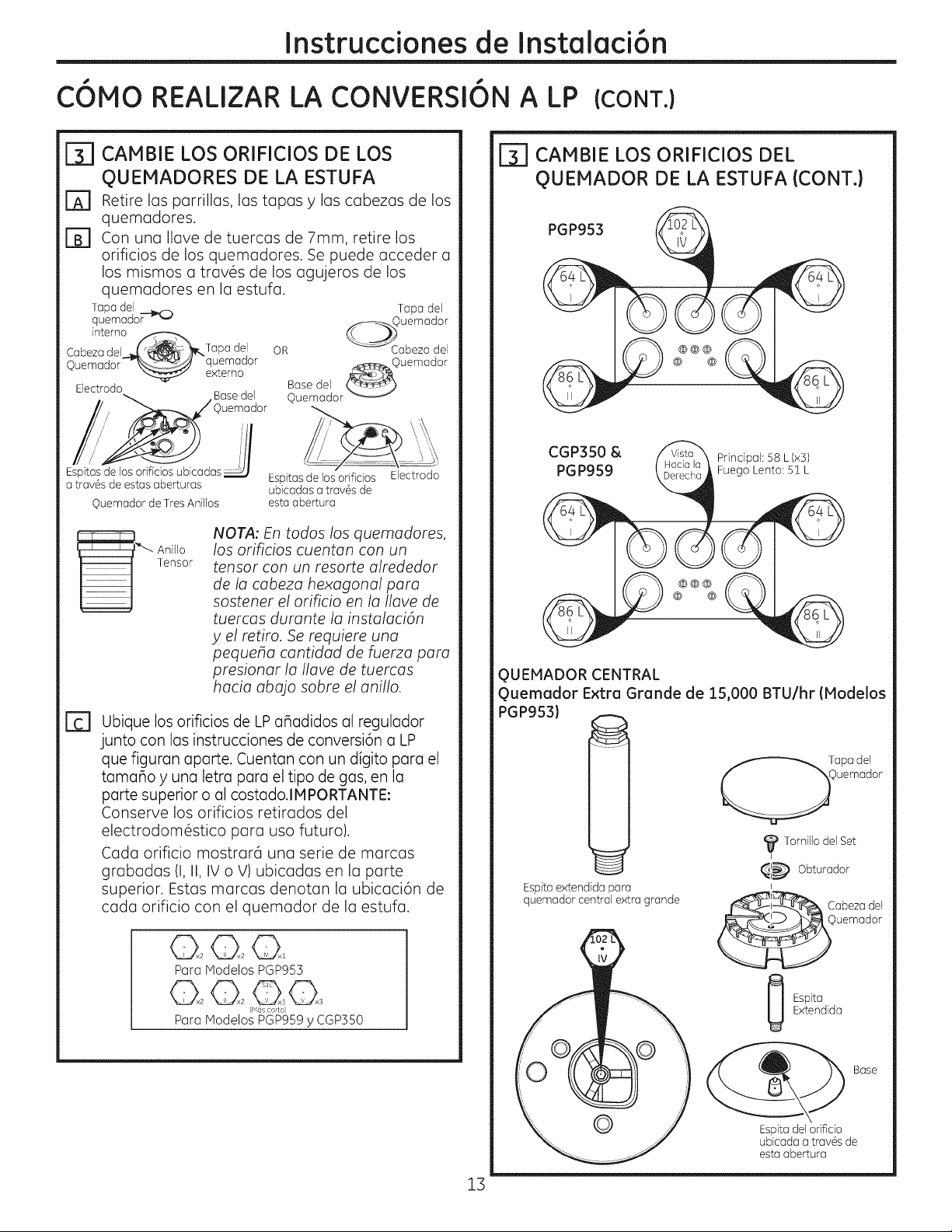
Instruccionesde Instalaci6n
C6MO REALIZAR LA CONVERSION A LP (CONT.)
CAMBIE LOS ORIFICIOS DE LOS
QUEMADORES DE LA ESTUFA
Retire los porrillos, los topos y los cobezas de los
E]
quemadores.
Con una Ilave de tuercas de 7mm, retire los
[]
orificios de los quemadores. Se puede acceder a
los mismos a trav6s de los agujeros de los
quemadores en la estufa.
Tapa del
quemado_
intemo
Cabezadel -_ _,- _, Tapa del
©uemador__ quemador
Espitasde los orificios ubicadas
a trav6s de estas aberturas
_exzerno
Electrodo
©uemador de TresAnillos
Base del
)uemador
OR _ Cabezadel
_©uemador
Base del _)
Ouemador -_*_-*-_
Espitasdelos orifidos
ubicadas a trav6s de
esta abertura
Tapa del
uemador
Electrodo
NOTA: En todos los quemadores,
_ Anillo
los orificios cuentan con un
tensor con un resorte alrededor
Tensor
de la cabeza hexagonal para
sostener el orificio en la Ilave de
tuercas durante la instalaci6n
y el retiro. Se requiere una
pequeha cantidad de fuerza para
presionar la Ilave de tuercas
hacia abajo sabre el anillo.
Fc-1Ubique los orificios de LPahadidos al regulador
junto con los instrucciones de conversi6n a LP
que figuran aparte. Cuentan con un digito para el
tamaho y una letra para el tipo de gas, en la
porte superior o al costado.IMPORTANTE:
Conserve los orificios retirados del
electrodom#stico para usa futuro).
Coda orificio mostrard una serie de marcas
grabadas (I, II, IV o V) ubicadas en la porte
superior. Estas marcas denotan la ubicaci6n de
coda orificio con el quemador de la estufa.
[_] CAMBIE LOS ORIFICIOS DEL
QUEMADOR DE LA ESTUFA (CONT.)
PGP953
CGP350 & PrindpaJ: 58 L(x3)
PGP959 Fuego Lento: 51 L
QUEMADOR CENTRAL
guemador Extra Grande de 15,000 BTU/hr (Modelos
PGP953}
_ Tornillo del Set
I
_l_ Obturador
Espita extendida para
quemador central extra grande
I
Cabezadel
020201
Para Modelos PGP953
IM(is colto)
Para Modelos PGP959y CGPS50
13
©uemador
Extendida
Espita
Espita del orificio
ubicada atrav6s de
esta abertura
Base
Page 46
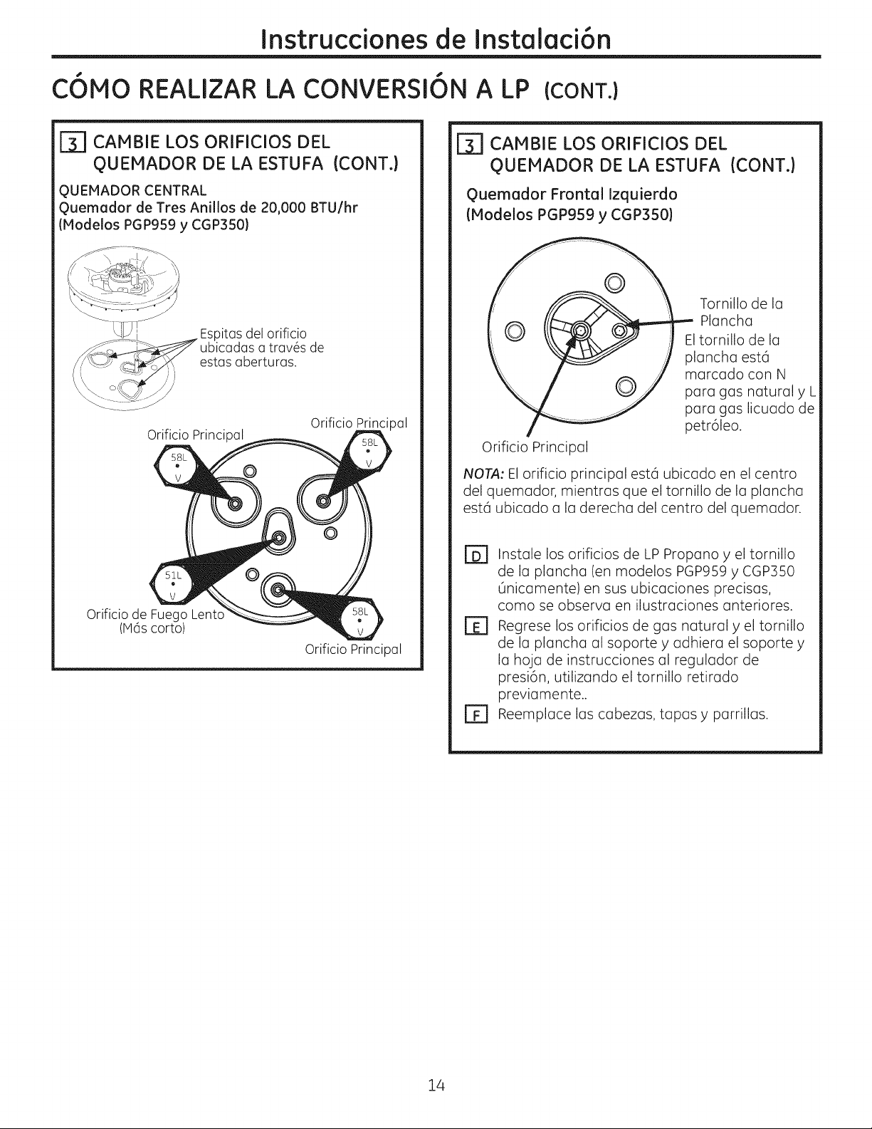
Instruccionesde Instalaci6n
COMO REALIZAR LA CONVERSION A LP (CONT.)
_7 CAMBIE LOS ORIFICIOS DEL
QUEMADOR DE LA ESTUFA (CONT.)
QUEMADOR CENTRAL
Quemador de Tres Anillos de 20,000 BTU/hr
(Modelos PGP959 y CGP350)
Ditasdel orificio
ubicadas a trav6s de
estas aberturas.
Orificio Princi )al
Orificio Principal
Orificio de Fuego Lent_
(M6s corto)
Orificio Principal
_7 CAMBIE LOS ORIFICIOS DEL
QUEMADOR DE LA ESTUFA (CONT.)
Quemador Frontal Izquierdo
(Modelos PGP959 y CGP350)
Tornillo de la
Plancha
Eltornillo de la
plancha est6
marcado con N
para gas naturaly L
para gas licuado de
petr61eo.
Orificio Principal
NOTA; El orificio principal est6 ubicado en el centro
del quemador, mientras que el tornillo de la plancha
est6 ubicado a la derecha del centro del quemador.
Instale los orificios de LP Propano y el tornillo
r64
de la plancha (en modelos PGP959 y CGP350
Onicamente) en sus ubicaciones precisas,
coma se observa en ilustraciones anteriores.
r_ Regrese los orificios de gas natural y el tornillo
de la plancha al soporte y adhiera el soporte y
la hoja de instrucciones al regulador de
presi6n, utilizando el tornillo retirado
previamente..
r_ Reemplace las cabezas, tapas y parrillas.
14
Page 47

Instruccionesde Instalaci6n
C6MO REALIZAR LA CONVERSION A LP (CONT.}
Prueba de Estabilidad de la Llama:
AJUSTE LAS LLAMAS DEL QUEMADOR
[]
Giretodos los quemadores al m6ximo y
controle las llamas. Deberian ser azules con
pequeBas puntas amarillas al final de la llama.
Particulas extraBas en la linea de gas pueden
ocasionar una llama anaranjada primero,
pero esta desaparecer6 enseguida.
r_ Girela perilladel quemadordela estufahastala
configuraci6nm6sbaja,mientrasobservala llama.
Ajuste la configuraci6n de la llama baja usando el
tornillo de desviaci6n de la v61vulacoma se indica:
Los ajustes en configuraciones bajas se deben
realizar con otros dos quemadores funcionando en
una configuraci6n media. Esto evita que la llama
baja se configure demasiado baja, hacienda que
la llama se extinga cuando otros quemadores se
encienden.
E] Para ajustar la llama,
retire las perillas. Use un
destornillador para
retirar los enchufes de
los v6stagos de las
v61vulas, coma se
muestra. Inserte un
destornillador a trav6s
del agujero de acceso en
el interruptor de la
v61vula.
Introduzca el tornillo
de ajuste en la v61vula.
Consulte la siguiente
ilustraci6n que enlaza la
ubicaci6n del tornillo de
ajuste de su modelo. El
quemador de la plancha y el tornillo de ajuste
de la cocina (PGPgg9 de fuego lento del
y CGP350) cuenta con
2 tornillos de ajuste,
uno para el quemador
trasero izquierdo y uno
para el quemador frontal
izquierdo durante el
control de la plancha. El
control de la plancha se
deber6 girar a LO (Bajo)
al realizar este ajuste.
. Si las llamas son demasiados bajas o se
agitan, abra la v61vula aOn m6s que la
configuraci6n original.
. Si las llamas son sopladas del quemador,
cierre la v61vula aOn m6s que la configuraci6n
original.
Lado izq
del v6stago
Para elquemador
frontal de la plancha
quemador de tres anillos
V6stago _-._
\wj
Para todos los que-
madores excepto el
de tres anillos
[E]
Prueba 1-
Prueba 2-
[] Vuelva a Controlar la Llama:
Una vez realizado el ajuste, apague todos
los quemadores. Encienda carla quemador
individualmente. Observe la llama en la posJci6n
"HI" (Alto). Gire la v61vula hasta la configuraci6n
m6s baja y aseg0rese de que el tama_o de la llama
se reduzca a medida que la v61vula es rotada en
contra de las agujas del reloj.
PARA CONVERTIR LA ESTUFA NUEVAMENTE A GAS
NATURAL, INVIERTA LOS PASOS DE LA CONVERSION
A LP.
Una vez completada y revisada la conversi6n,
reemplace las perillas y enchufes de la v61vula
del v6stago, y complete la etiqueta de LP.Incluya
su nombre, organizaci6n y fecha en que la
conversi6n fue realizada. Pegue la etiqueta cerca
de la abertura de entrada de gas de la estufa para
alertar a otras personas en elfuturo de que este
electrodom6stico fue convertido a gas LP.Si se
convierte nuevamente de LP a gas natural, retire la
etiqueta de modo que otras personas sepan que
el electrodom6stico se configur6 para usa con gas
natural.
Perillas de reemplazo temporario.
Girela perilla de "HI" (Alto)a
la configuraci6n m6s baja
r6pidamente. Sila llama se apaga
en la configuraci6n m6s baja,
incremente el tama_o de la llama
y haga la prueba nuevamente.
Con el quemador en la
configuraci6n m6s baja, abra
y cierre la puerta del gabinete
debajo de la estufa. Si la llama se
extingue par las corrientes de aire
creadas par el movimiento de la
puerta, incremente la altura de la
llama y vuelva a hacer la arueba.
rD] Haga el ajuste girando lentamente el tornillo
hasta que el aspecto de la llama sea el
correcto.
15
Page 48

Notas.
16
 Loading...