

Page 1

INSTRUCTIONS
GEK-26423D
TYPE
GROUND
CEYG51A
DISTANCE
RELAY
Protection
GE
205
Great
Maivern,
and
Valley
19355-1337
PA
Control
Parkway
Page 2

iNTRODUCTION
APPLICATION
RATINGS
Contacts
OPERATINO
PRINCIPLES
CHARACTERISTICS
Pickup
Operating
Time
Burden
CALCULATION
OF
CONSTRUCTION
RECEIVING,
ACCEPTANCE
Visual
HANDLING
TESTS
Inspection
Mechanical
Electrical
iNSTALLATION
Relay
PROCEDURE
Settings
Mechanical
Electrical
EQUIPMENT
PORTABLE
TEST
SERVICING
Restraint
Circuit
Directional
Maximum
Torque
Pickup
Clutch
RENEWAL
Adjustment
PARTS
SETTINGS
AND
Inspection
Tests
Checks
Checks
Characteristic
Angle
STORAGE
Angle
Adjustment
GEK-26423
NTS
E
CONT
PAGE
3
3
4
4
5
5
6
6
6
7
9
9
10
10
10
10
11
11
11
11
11
14
15
15
15
15
15
16
MINIMUM
Zero
No
With
MAXIMUM
No
Zero
MAXIMUM
With
PERMISSIBLE
Sequence
Sequence
Zero
PERMISSIBLE
Sequence
PERMISSIBLE
Sequence
Zero
REACH
Current
Current
REACH
Current
REACH
Current
SETTING
Compensation
Compensation
SETTING
Compensation
SETTING
Compensation
FOR
FOR
FUR
THE
THE
THE
APPENDIX
CEYG51A
APPENDIX
CEYGS1A
APPENDIX
CEYGS1A
I
17
17
18
II
18
18
III
20
20
2
Page 3

GEK-26423
The
consists
target
reach
a
and
characteristic
first-zone
comparison
The
missive
tion.
The
faults.
be
will
ground
also
will
faults
any
The
tion.
sequence
zero
phase
to
unit
niho
minimum
In
terminal.
against
trip
and
sequence
the
on
coordinate
must
should
carrier
In
minal.
protected
The
length
required
reach
the
proper
ditions
mho
unit
minimizes
pedance
CEYGS1IX
three
of
seal-in
relay.
and
CEYG51A
overreaching
ground
this
To
high
quite
faults.
respond
not
ground
A
tapped
current
ground
reach
permissible
directional
These
single
all
internal
for
current
carrier
set
be
as
signal
permissive
acts
It
line
choice
system
and
coverage.
on
or
reach
its
present
three
a
is
single-phase
unit
of
The
transferred
ground
transferred
units
rnho
they
end
and
this
For
to
involving
units
mho
auxiliary
faults
considerably
is
reach
comparison
relays
phase
compensation
starting
will
sensitively
block
will
overreaching
a
as
section.
whether
of
conditions.
be
may
swings.
power
setting
response
from
phase,
provides
the
CEYG51A
relay
tripping
relay
mho
the
of
are
relay
the
reason,
phase
three
ground
provided
are
current
compensation
on
as
settings
operate
ground
to
faults
while
units.
operating
be
as
tripping.
combined
or
2
about
then
This
approximately
to
load
to
parallel
a
high
units
indication
relay
specifically
waS
schemes.
applied
is
tripping
CEYG5IA
supplied
will
these
faults.
simply
transformer
is
phase
three
foreshortened
under
schemes,
conjunction
in
faults
the
used
is
This
on
possible.
transferred
transferred
to
not
When
3
to
tends
use
The
or
power
line.
speed,
in
with
have
by
with
used,
on
will
the
use
zero
times
to
of
GROUND
one
has
schemes,
relay
units
If
adding
faults.
both
two
in
other
the
facilitate
same
trip
sequence
sequence
the
make
zero
1.25
swings.
DISTANCE
CEYG51A
INTRODUCTION
single
L2—D
case
of
operation
been
not
designed
Figure
APPL
the
primary
as
employing
specifically
are
quadrature
operating
high
a
not
are
is
this
non—directional
a
separate
used
is
the
ground
If
single
on
conditions.
CEYG51A
relays
with
protected
the
initiates
carrier
torque
will
This
tripping
initiating
current
current
positive
ground
the
sequence
the
times
This
RELAY
RELAY
mho
zone,
with
facilities
for
limited
for
3
shows
CAT
ION
I
ground
voltage
provided
objectionable,
current
obtain
to
unit
iiho
sequence
zero
phase
connected
a
carrier
line
carrier
stopping
the
unit
level,
to
tend
schemes,
and
compensation
compensation
sequence
mho
current
positive
true
is
type,
three
all
to
the
use
as
the
internal
relay
separate
designed
polarization.
torque
with
circuits
the
has
ground
to
channel
section.
blocking
tripping
and
settings
any
in
increase
CEYG51A
one
permissive
a
impedance
more
unit
compensation
sequence
provided
directional
for
testing
distance
point
an
overreaching
connections.
directional
in
primary
detect
to
level
even
memory
zero
the
for
proper
action.
relay
sequence
zero
ratio
essentially
compensation
faults.
back—to-back
provide
to
One
external
on
units,
insure
and
event,
the
security
relay
relay
depends
NOT
is
of
sensitive
impedance
there
units.
where
and
Thus,
on
can
sequence
relay
carrier
since
is
upon
used,
the
reduces
is
distance
one
is
it
device
separate
single
the
very
These
made
be
fault
compensation.
of
same
the
NOT
is
Appendix
See
required
are
high
acts
faults.
should
it
that
the
required
ground
for
the
the
line
operation
to
the
of
little
ground
unit
atatime.
The
suitable
in
comparison
backup
phase
polarizing
close
ground
unresponsive
detector.
current
reach
used,
speed
to
both
starting
presence
at
protected
ground
order
in
necessary
the
line
no
or
relay.
transient
for
directional
to
line
in
niho
compensa
on
ground
the
for
I
each
at
protection
carrier
Stop
zero
if
be
also
units
unit
each
faults
mho
to
on
and,
mutual
use
and
protec
ground
voltage
to
units
When
single
the
used
that
a
of
ter
in
line
unit
provide
load
ground
thus,
im
It
One
over
as
per
to
the
con
eeerc
furtn-r
tn
These
poss:ble
information
purchaser’s
To
he
:ot
sucn
nstroctions
contanJencj
purposes,
extent
-scranc.
be
,eau:red
do
desired
s
not
to
the
;iven
the
purport
be
or
matter
met
should
products
with
to
in
should
respect
cover
connection
particular
be
descrrhed
to
all
referred
local
details
with
problems
herein
installation,
to
codes
the
meet
or
arise
and
variations
which
General
applicable
ordinances
in
operation
are
Electric
?.ESI,
equipment
not
because
or
maintenance.
covorci
Ccmpant.
IEEE
he;
and
nor
sufficientlq
.S1IMA
varo
to
provide
standards;
rcatly.
For
Should
for
Page 4

GEK-26423
Whether
correct
line
the
avoid
to
sequence
setting
The
II
fault
zero
will
in
and
behind
If
sequence
permit
Figure
Ill
the
Since
performance
sired
setting
The
operation
to-phase.
ohmic
The
by
steps
will
It
desired
the
The
positions
reach
ohmic
or
operation
impedance
this
current
zero
when
system
are
,
the
reach
tripping
4.
the
will
CEYG5IA
Type
wye-wye
on
Current
BASIC
OHMIC
(0-N
1/2/3
0.5/1.0/1.5
reach
means
be
basic
setting
MINIMUM
zero
not
on
and
tripping.
false
compensation
sequence
conch
tions
rather
relay
the
of
directional
CEYG51A
obtained
be
used.
is
coil
MIN.
REACH
OHMS)
at
is
of
a
noted
minimum
the
of
sequence
ground
system
unusual
is
unfaulted
only
an
is
relays
connected
ratings
the
tapped
that
sets
two
follows:
as
OHMIC
current
faults
immediately
conditions.
Appendix
NOT
is
requ
They
.
than
compensation
current
which
larger
phase
overcurrent
fault
the
when
extended
the
if
covered
potential
and
RANGE
OHMIC
(0-N
of
angle
autotransformer.
basic
three
is
reach
REACH
links,
of
SETTING
compensation
II
used
the
cc
occur
the
units
relay
is
range
highest
these
by
transformers
ohmic
REACH
OHMS)
-
1
-
0.5
maximum
minimum
by
made
(for
(OHM
is
the
used.
is
tdtion
the
sequence
the
forward
with
minimum
the
limiatations
ill
of
zero
non-trip
nay
three
behind
nayhenecessary
It
gives
Appendix
im
1
when
positive
ii
(CFPG16A)
the
in
relay
basic
RATINGS
instructions
which
as
ranges
are
30
15
of
of
N
60
settings
links
unit),
torque
reach
means
each
PHASE-TO-NEUTRAL)
used,
relay
gives
uho
the
sequence
current
direction
used
be
direction.
basic
reach
available
are
supply
tabulated
CONTIN.
CURRENT
AMPERES
degrees
are
terminal
on
each
the
ground
terminals.
1
mit
to
of
the
limitdtions
unit
current
to
minimum
tap
secondary
below:
RATING
5
5
lag,
listed
identified
A
+
mho
This
mho
the
mho
the
reach,
contribution
contribution.
an
is
supervise
external
The
reach
setting
that
with
can
and
for
boards
as
B
units
will
unit
unit
reach
the
of
as
described
application
the
settings,
will
potential
voltage
—
adjusted
be
mho
the
located
A-B
may
be
dependent
be
reach
setting
inho
over
CEYG51
connections
accommodate
circuits
of
120
SEC.
ONE
RATING
CUR.
AMPERES
225
225
units.
rear
on
determine
subject
setting
unit
reach
by
Appendices
the
limitation,
operation.
best
the
volts
percent
5
in
Selection
of
the
to
upon
in
when
line
shown
are
overall
the
rated
phase-
the
minimum
in
order
zero
to
a
This
de
for
of
relay.
a
CONTACTS
main
The
tripping
always
by
amperes,
current
The
shown
as
circuit-closing
at
duty
opened
tripping
a
Table
in
I—C
Carry
Carry
Carry
control
an
by
relay
carrying
I
Resistance
Continuously
Amps
30
Amps
10
voltages
auxiliary
should
rating
for
for
contacts
switch
be
of
of
used.
the
——
of
250V
main
the
DC
other
or
contacts
TARGET
2.0
Amp
0.13
3.5
re1a
or
Tap
4
less.
suitable
TABLE
AND
Ohms
Amps
Secs.
will
The
is
I
SEAL-IN
4
and
close
circuit
means.
determined
UNIT
0.6
A;np
0.6
1.0
0.5
carry
breaker
the
If
by
Tap
Ohms
Amps
Secs.
the
amperes
30
trip
tripping
tap
—
coil
setting
DC
momentarily
should,
current
of
0.2
Amp
7
0.35
0.2
Tap
Ohms
Amps
Secs.
exceeds
the
for
however,
30
seal—in
coil
Page 5

0.3
normally
The
amperes
closed
in
non—inductive
contacts
circuits
between
up
terminals
250V
to
GEK-26423
and
19
DC.
20
will
close,
carry
continuously,
or
interrupt
inhu
The
Fig.
with
6)
phase-to-phase
polarizing
tdye
vol
in
izing
the
The
of
rear
flux
torque
following
where:
type
schematic
flux.
the
pole,
produce
to
equation:
Ebc’
units
voltage
flux
The
protected
which
operating
balance
the
at
Torque
design
K
Phase—A-to-neutral
=
Phase
=
Phase
=
‘a
Angle
=
B
Restraint
=
T
Angle
=
CEYGS1A
the
in
connections
in
quadrature
in
phase,
energized
is
0
=
constant
to
B
current,
A
by
by
relay
shown
as
with
front
the
interacts
by
torque.
point
for
KIaEbc
=
PhaseCvoltage
at
Ea
setting
‘a
leads
which
tap
which
OPERATING
are
in
Fig.
the
phase-to—neutral
which
pole,
the
the
the
with
line
phaseAstarting
((
COS
voltage
relay
the
Ebc’
leads
Ebc
PRINCIPLES
of
the
3.
is
polarizing
current
-30)
the
at
(Eb
location
(900
four-pole
The
energized
—
TEEb’
relay
E)
-
for
of
balanced
induction-cylinder
two
side
voltage
by
flux
the
protected
can,
unit
sin
location
at
the
poles,
percentage
a
to
produce
B
relay
3-phase
which
the
of
phase,
therefore,
are
protected
of
restraint
interacts
be
(1)
condition)
construction
energized
phase,
the
phase-to-neutral
torque.
with
expressed
(see
the
by
produce
The
the
the
by
the
flux
polar
The
impedance
rather
The
diameter
current
line
there
maximum
this
voltage
The
which
compensated
not
special
positive
the
selecting
The
applied
tap
the
operating
specific
inho
passing
essentially
is
by
diameter
would
case
ohmic
to
block.
diagram
as
fault
characteristics
has
unit
through
for
(Ia
torque
600,
which
of
be
is
it
single-phase—to-ground
of
basic
the
sequence
reach
a
setting.
reach
restraint
the
Ohmic
shown
conditions
circular
a
example)
phase
no
angle
is
the
not
impedance
the
of
Fig.
in
origin
the
leads
shift
(i.e.
condition
the
impedance
minimum
accurate
an
mho
circuit,
ReQch
of
the
7.
described
characteristic
defines
the
in
maximum
circle
reach
distance
the
to
can
unit
that
2
=
Tap
E
CHARACTER
mho
units
should
It
below:
the
quadrature
the
line—to—neutral
reach
represented
would
with
the
faults
fault.
extended
be
by
is
setting
(Zi)
Setting
in
be
which
angle
polarizing
angle)
in
nomally
tap
E
measuring
where
Instructions
100
()
1ST
the
noted
passes
of
occurs
Fig.
be
leads
zero-sequence
the
reducing
by
the
1
CS
CEYG51A
that
through
maximum
voltage
voltage
when
8.
considered
on
until
are
tap
E
2
(5)
represented
be
may
relay
these
steady-state
torque
the
origin
of
(Ebc
the
for
of
unit,
example)
forasingle-phase-to-ground
current
line
the
ohmic
the
100
except
given
the
leads
as
percent.
on
impedance
in
percentage
on
However,
3-phase
Appendices
of
lower
a
to
characteristics
R-X
the
which
by
the
lags
reach
if
faults,
fault
the
and
II
fault
the
percentaoe
R—X
the
on
are
diagram.
occurs
30°.
when
Since
fault,
phase—to-neutral
unit,
the
of
niho
for
unit
the
equal
is
for
the
or
III
voltage
position
for
The
is
to
on
5
Page 6

The
(600).
equation
from
PICKUP
The
ufficient
for
mum
percent
On
result
percent
current
ohmic
reduced
The
operating
magnitude
fault
voltage
by
(5)
currents
with
reach
cos
torque
to
which
currents
obtained
reach
MINIMUM
REACH
(0-N
0.5
1.5
single-phase-to-ground
will
relay
the
that
restraint
for
the
voltage
3-ohm
minimum
from
line
at
(60-0)
will
overcome
lag
OHMIC
SETTING
OHMS)
1
2
3
operate
and
close
as
faults
120
reach
equation
angles
where
the
restraint
the
unity
the
tabulated
at
volts
setting.
(5)
other
is
the
0
contacts
power
below:
quadrature
the
considerably
polarizing
GE
K—2
assumes
than
line
when
torque.
factor
CURRENT
64
23
that
600
can
angle.
the
The
position
polarizing
current
less
unit
the
line
be
fault
operating
RANGE
will
angle
obtained
current
by
FOR
36
18-60
12
9
6
potential
than
operate
maximum
and
multiplying
by
is
torque
degrees
60
RELIABLE
60
-
60
—
60
-
60
-
will
tabulated.
with
certiri
in
a
3-phase
on
and
OPERATION
remain
less
torque
is
For
than
angle
reach
the
direction
faults
reliable
quite
example,
ampere
1
high
are
obtained
is
down
with
with
equal
of
and
maxi
a
one
to
the
one
a
operating
OPERATING
typical
For
BURDEN
burden
The
percent
100
at
Basic
Ohms
1
0.5
1
the
I-f
equation:
where
TIME
30
-
15
-
30
-
restraint
Watts
VARS
T
operating
imposed
as
is
Rated
Freq
Restraint
Restraint
=
Tap
given
60
60
50
tap
VA
on
in
time
the
below:
reduced,
is
Watts
=
circuit
circuit
percent.
characteristics
potential
Polarizing
V
120
120
120
Watts
10.1
10.1
8.41
the
*(2
watts
Vars
see
transformers
Circuit
Vars
burden
+
.
table
from
table
from
Figure
by
8.88
8.88
7.38
of
the
VARS(i”)
above.
above.
13A
type
the
VA
13.5
13.5
11.2
restraint
and
CEYG51A
circuit
138.
Volts
70
70
70
relay
Restraint
Watts
2.7
0.9
1.7
given
is
with
the
Circuit
by
Vars
4.0
1.6
3.0
the
restraint
following
VA
4.8
1.8
3.4
tap
set
6
Page 7

The
burdens
imposed
on
the
current
transformers
GEK-26423
the
by
current
circuits
are
given
below:
quently
be
followed
Basic
Ohms
1-3D
0.5
1
NOTE:
applying
In
do
Determimimme
1.
the
line
Determine
2.
relay
a.
b.
c.
following
The
Consider
-
15
-
30
Above
for
materialize.
not
determine
to
necessary
power
terminal.
When
further
When
further
no
neither
If
determine
lay,
the
Rated
Freq.
data
the
the
relay
if
zero
loadings
if
there
zero
evaluation
zero
Type
calculations
protected
60
60
50
is
lower
to
what
sequence
unit
rnho
and
is
sequence
sequence
evaluation
nor
a
if
it
CFPH16A.
line
3-4,
I
5
5
5
for
the
reach
particular
a
Therefore,
final
tap
power
limitation
a
current
need
current
above
b
is
necessary
are
to
5-6,
0.070
0.007
0.058
mho
settings
tap
calculations
current
settings
swings.
compensation
made.
be
compensation
be
need
is
made
between
be
7-8
or
Circuit
X
0.040
0.005 0.008
0.033
units set
on
will
CALCULATION
line
and
system,
recommended
it
is
maybenecessary
compensation
and
the
Appendix
See
application
the
in
Appendix
See
made. See
applicable,
use
an
the zero
example
to
as
breakers
their
be
less
SETTINGS
OF
is
relation
is
t.{Qi
is
used:
Appendix
evaluate
of
A
2
0.080
0.067
maximum
than
the
limitations
the
that
required.
the
of
equations
I,
for
used:
equations
II,
if
III,
the
sequence
determining
and
B
on
1
5
5
5
ohmic
the
initial
and
This
resulting
incorrect
if
Co
(3K
equations
equations
directional
the
0.210
0.021
0.175
tabulated
how
‘b
is
ha,
+
1)
actual
the
portion
Circuit
9-10
R
reach
taps.
burdens.
outlined
calculations
the
relay
will
depend
mho
and
I.
operation
equal
hib
equal to
Co
is
lIla,
of
either
overcurrent
tap
of
X
0.120
0.013
0.100
The
under
of
may
be
upon
characteristic
on
or
less
to
tIc.
and
and
hlIb
Appendix
settings
system
a
Z
0.240
0.024
0.200
burden
APPLICATION
and
2
1
applied.
evaluation
on
with
than
less
behind
C,
than
faults
or
Ihic.
II
or
supervising
be
to
in
shown
fre
below
no
III
used.
Fig.
of
the
the
C,
to
re
5.
Assume
Checking
breaker
the
Z
1
CT
Ratio
PT
Ratio
Secondary
=
21
Z0’
=
Zom
Appendix
detect
A
to
following
=
24.0
=
72.0
14.4
600/5
1200/1
Ohms
2.4
/79°
/75°
7.2
/75°
1.4
a
characteristics:
/790
/750
/75°
=
CT
PT
=
0.47
=
1.9
=
0.36+jI.35
first
I
single
primary
primary
primary
Ratio
Ratio
to
phase
ohms
ohms
Primary
x
+
j2.36
+
j6.95
establish
to
ohms
secondary
secondary
secondary
ground
Ohms
the
fault
ohms
ohms
ohms
maximum
(F2)
7
tap
at
setting
the
remote
that
bus,
would
Equation
still
permit
should
lb
the
CEYG5IA
used.
be
at
Page 8

GEK-26423
Assume
Substituting
obtain:
we
The
should
restraint
Consider
calculate
double
or
constants:
value
be
for
C
0
C
10’
used.
tap
the
phase
this
=
=
=
=
=
=
9
these
T
=
of
T
For
T
should
T
=
a
now
maximum
to
fault
0.17
0.20
13.7
4.1
-0.88
negative
from
790
0.204K
could
the
0.204K
ground
safe
ground
at
secondary
secondary
secondary
sign
that
values
F
obtained
be
three
no
be
=
fault
reach
faults
F2
in
and
+
larger
61
that
amperes
amperes
amperes
because
which
the
(7.2
(0.4
ohm
percent
at
setting
at
system
a
I
I
flows
values
K
-2.4)(0.17)
0.17)
÷
all
for
basic
than:
immediately
Fl
this
study
based
based
flows
of
Cos
three
reach
to
eliminate
location.
yields
600/5
on
the
on
in
the
in
impedance
(60-79)
(1.4)(-0.88)
+
basic
settings
behind
CTs
protected
opposite
the
protected
13.7
K
the
Assume
following
the
assumed
minimum
300.
relay.
the
possibility
that
line
direction
line
above
reach
Thus,
system
a
quantities.
CT
ratio
(A
to
into
settings.
for
Appendix
an
of
study
in
B).
equation
this
incorrect
of
the
H
yields
600/5.
parallel
However,
basic
indicates
Note
of
Tb
the
setting
tap
operation
following
the
the
line
Appendix
highest
approach
the
on
(0
to
I,
the
single
system
C)
one
to
TIc
Using
of
C
C
0
Z
1
the
Appendix
0.27
0.11
=
tap
ohms
ohms
settings
ha)
JIb)
lIc)
established
values
above
setting
tap
of
tabulated
are
T
evaluating
and
equations
below.
ha,
and
JIb
VALUE
0.875
1.05
/82°
/780
1.2
0.11
0.27
100
123°
82°
Percent
-10.5
Percent
-18
Percent
-14.5
0.875
=
1.05
=
1.2
=
basic
ohm
3
the
II,
secondary
/780
minimum
minimum
secondary
permissible
QUANTITY
ZI
Z
0
Z0/Z
1
Co
C
K
A
8
(Equation
T
(Equation
T
(Equation
T
8
Page 9

GEK-26423
Since
tap
the
Since
setting
remote
These
the
If
tings
be
at
carrier
the
terminal
set
be
setting.
reach
Thus,
setting
should
terminal.
application
of
least
as
In
any
setting
If
zero
we
all
the
61
the
same
carrier
the
1.25
starting
and
they
sensitively
case,
Thus,
as
sequence
obtain.
values
for
this
percent
used.
be
Thus,
calculations
for
is
starting
times
relay
will,
as
ALWAYS
carrier
the
tripping
the
current
of
T
application.
setting
is
It
50
for
T
=
Set
should
directional
the
setting
at
therefore,
possible.
the
set
start
K
the
in
above
will
desirable
percent
61
41
40
on
tap
be
CEYG51A
of
rear
the
coordinate
relays
CEYG51A
CEYG51A
compensation
-
6.95
=
3(2.36)
table
Thus,
insure
the
that
to
set
additional
percent
percent
repeated
comparison
relays
the
at
tripping
terminal
must
that
relay
at
relay
used,
is
2.36
= =
are
relays
the
the
reach
the
for
carrier,
both
relay
will
properly.
coordinate
terminal
at
terminal
equation
4.59
7.08
negative,
maybeset
relay
relay
the
relays
terminals.
outreach
A.
0.65
to
it
at
In
these
will
reach
restraint
at
will
the
remote
the
any
event
with
should
B
should
Ic
per
in
reach
at
the
also
The
carrier
each
unit
equations
range
the
only
least
setting
tap
remote
necessary
be
carrier
terminal.
tripping
carrier
the
other
set
be
be
used
impose
of
the
to
25to50
should
of
end
start
This
starting
the
on
the
with
instead
no
restrictions
10to61
remote
percent
be:
line
the
determine
to
settings
relay
will
at
relay
basic
same
same
equation
of
percent.
bus,
at
insure
the
units
basic
a
lower
beyond
terminal
the
remote
should
minimum
minimum
on
the
B.
set
should
that
tap
lb.
For
maximum
the
The
associated
restraint
details
tion
The
cradle
the
plug
is
case
can
attaches
the
vent
Outline
These
protect
transit.
transportation
the
Reasonable
immediately,
metallic
and
is
cover
ground
the
safe
CEYG51A
Type
tapped
circuits
of
components
locked
block
and
inserted
be
the
to
from
cover
and
relays,
against
them
injury
If
care
they
chips.
removed
fault
setting
reach
relay
autotransformer
adjustment
for
relay.
the
mounted
are
case
the
in
cradle
place
in
from
case
being
drilling
panel
not
when
damage.
damage
or
company
should
should
Foreign
cause
and
=
T
immediately
F2
consists
Internal
by
block
the
replaced
included
and
be
stored
be
matter
trouble
0.33K
using
when
of
for
of
angle
connections
a
cradle
on
means
completed
are
connection
the
of
front
and
until
dimensions
RECEIVING,
as
Immediately
resulting
promptly
exercised
in
collected
in
0.33
=
behind
zero
three
controlling
and
assembly
latches
of
includes
the
are
part
a
upon
from
notify
unpacking
in
original
their
operation
the
300=99
x
the
sequence
percent
relay,
current
CONSTRUCTION
reach
of
4—pole
and
minimum
relay
the
inho—type,
basic
which
the
at
through
plig
the
connection
shown
a
to
target
in
top
removable
permit
plug
Figure
HANDLING
control
a
of
receipt
rough
the
of
handling
nearest
the
cartons
outside
the
on
the
of
use
adjustable
can
and
reset
AND
panel,
a
General
relay.
relay.
equation
the
compensation.
induction
ohmic
shown
are
easily
be
bottom.
connection
testing
mechanism
been
has
15.
STORAGE
will
relay,
evident,
is
If
a
place
in
of
the
resistors
reach.
the
inserted.
be
examine
Electric
the
case
of
cylinder
Figures
Figure
in
removed
electrical
The
plug.
relay
and
shipped
it
a
file
Apparatus
relays
that
find
may
Appendix
units.
in
3.
from
in
an
in
any
for
damage
are
is
free
its
III
Each
polarizing
the
and2show
1
relay
the
connections
separate
A
case.
its
interlock
cartons
damage
claim
Sales
not
to
from
way
calculate
to
unit
case.
testing
The
armtopre
designed
ststained
once
at
Office.
installed
be
moisture,
inside
has
and
construc
between
cover
with
dust,
when
an
The
to
in
the
9
Page 10

GEK-26423
Immediately
damage
no
ViSUAL
has
INSPECTION
Check
received
agree
Remove
molded
parts
MECHANICAL
is
It
There
1.
so
tact
There
the
There
check
contacts
2.
lower
shaft
3.
.012
4.
that
5.
assembly
6.
should
armature
should
that
7.
There
The
inch
The
it
The
The
Check
closed
The
the
to
connection
blocks,
gram.
Note
high
the
and
Figure
that
enough
main
improper
circuited.
upon
been
nameplate
the
with
relay
the
other
or
INSPECTION
recommended
should
should
should
screw
jewel
locked
by
contact
clearance
spring
touches
just
clutch
at
armature
a
be
hand
by
at
be
target
the
the
diagram
that
11
is
there
that
so
brush.
adjustment
receipt
sustained
the
from
signs
that
be
be
bearing
its
gap
windup
of
moving
the
and
screw
and
least
location
for
long
the
shows
an
when
This
of
stamping
requisition.
its
of
the
noticeable
no
closed
be
end
an
set
each
on
between
should
the
unit
each
contacts
only
in
check
1/32
resets
the
and
sectional
a
auxiliary
the
especially
is
the
the
of
shipment
in
to
case
physical
following
play
of
screw.
unit
the
solid
contact.
that
wipe
positively
the
of
relay.
short
connecting
auxiliary
relay
insure
and
when
each
stationary
be
stop
should
of
one
contact
brush
and
check
damage,
friction
the
from
of
unit
should
sufficient
when
slip
the
the
of
the
the
on
sure
Be
brushes
view
in
important
brush
ACCEPTANCE
inspection
an
that
that
by
mechanical
in
relay
.005
should
approximately
be
contact
the
when
target
tap
target
seal—in
the
when
brushes
that
on
the
of
position
each
is
plug
could
the
model
the
visual
that
and
adjustments
the
in
is
to
be
cause
to
unit
force
a
and
positions
latches
contacts.
reset
on
the
cradle
the
case
inserted
current
in
result
TESTS
and
relay
number,
inspection
all
rotating
the
inches
.015
screwed
rod
the
dc—energized.
is
of
seal-in
in
button
the
shorting
cradle
and
on
in
acceptance
calibrations
screws
structure
upright
firmly
.045
the
and
normally
45
unit
the
on
exposed
its
With
at
cradle
bars
block
the
engages
it
other
and
CT
a
rating,
that
be
position.
on
to
solid
to
should
right
the
and
agree
blocks
case
secondary
test
there
are
checked:
the
in
.065
closed
grams
65
stationary
position
the
5ottom
case
are
with
with
block.
the
circuits
have
and
tight.
of
shafts
place,
inches.
backstop
move
cover
blocks
the
in
auxiliary
should
not
ohmic
are
each
of
and
stationary
applied
is
freely
fastened
of
proper
the
the
This
with
circuit
made
be
been
range
broken
no
unit.
rotating
the
the
There
when
when
contact
before
cover
the
against
locations
internal
connection
brush
brush
shorting
being
to
disturbed.
of
or
The
pivot
should
contact
the
contact
the
to
operated
strip.
contacts
the
securely
is
the
connection
plug
should
before
momentarily
insure
the
cracked
normally
structures.
the
at
to
moving
operated.
internal
on
be
bars
relay
top
.004
be
is
deflect
by
Operate
place,
in
the
place.
in
formed
striking
since
that
of
open.
con
hand.
close.
case
dia
an
open
ELECTRICAL
is
It
Polarity
1.
polarizing
connections
test
the
the
CaUSe
unit
that
Directional
2.
characteristics.
phase
the
contacts
on
closed
100
remain
be
TESTS
recommended
Check
restraint
and
contacts
should
develop
shifter
of
the
as
unit
each
percent
of
Use
so
for
that
-
in
that
Check
the
that
should
current
these
the
The
circuits
Figure
a
-
test
the
following
unit
strong
The
current
close
is
tests.
following
each
of
With
9.
close.
to
contact
following
connections
at
increased
electrical
check
all
leads
some
will
unit
tap
With
opening
checks
shown
the
value
the
to
insure
correct,
is
leads
the
torque.
are
in
voltage
less
maximum
checks
removed
tap
E
2
to
Figure
than
10
made
be
that
Each
of
determine
10.
30
by
the
value
relative
the
unit
connections
the
each
Set
degrees
minimum
given
immediately
can
set
unit
each
that
voltages
the
with
amperes
Table
in
polarity
checked
be
in
unit
the
upon
shown
80
the
has
to
connections
given
III.
receipt
operating,
of
individually
each
for
percent
correct
volts
two
Tble
in
EL
The
the
of
unit
position,
directional
and
shown.
III
taps
relay.
using
should
set
The
and
should
Page 11

GE
K-
TABLE
26423
III
Set
should
unit
3.
connections
amperes,
for
5
With
unit
the
of
contact
bisector
the
at
the
unit
The
operating
4.
percent
+14
set
and
at
with
100
voltage
Table
in
phase
the
phase
the
remain
Maximum
shown
the
phase
will
just
to
left
maximum
current
Pickup
of
percent
relay
the
30
by
IV.
angle
shifter
Torque
in
with
be
open.
of
contact
torque
leads
Check
the
degrees,
Resistor
of
OHMIC
SETTING
TAP
0.5
1.0
1.5
2.0
3.0
from
open
Angle
Figure
polarizing
shifter
closed.
These
the
angle
just
angle
the
-
The
minimum
and
the
connected
check
R11-R12-R
13
restraint
the
REACH
that
so
zero
-
10,
set
Next
are
between
opens
(110
of
polarizing
following
reach
voltage
as
that
the
to
The
but
voltage
that
so
find
the
at
310)
+
the
as
shown
the
circuit
current
amperes.
60
maximum
with
at
operating
the
zero
the
1100
210°,
=
units
voltage
check
given
adjusted
in
current
should
torque
the
120
angles
torque
two
and
should
is
on
for
Figure
not
the
leads
tap
E
volts.
zero
3100.
ie
for
to
the
the
10.
required
be
same
MINIMUM
AMPERES
32
16
12
8
6
the
angle
disconnected.
current
either
on
angles
torque
The
3Q0
lead
300
be
at
particular
a
determine
nameplate.
value
Set
to
used
to
the
as
voltage
the
of
leads
the
of
lines.
angle
lead,
that
shown
the
close
adjust
phase
by
mho—type
polarizing
side
unit.
of
unit.
the
These
in
phase
the
pickup.
angle
degrees.
210
operating
The
the
of
The
example,
For
maximum
This
+3°.
ohmic
checks
Table
shifter
contacts
of
units
voltage
300
position
maximum
torque
reach
should
IV
so
The
the
MAXIMUM
AMPERES
60
60
60
60
60
The
can
be
current
by
torque
assume
will
the
is
angle
each
of
be
for
the
current
that
within
falls
resistors
polarizing
contacts
checked
30°,
which
that
be:
unit
made
specific
are
circuit.
using
should
the
cause
position
for
which
by
is
with
ohmic
leads
the
used
each
of
be
left
the
particular
a
witin
the
range
to
the
set
contact
will
the
E
range
shown
make
left
be
taps
UNIT
-N
0.5
2.0
3.0
Compensating
5.
compensating
connect
but
With
the
close
1.0
1.5
windings
the
voltage,
left
current
UNiT
E
2
contact
REACH
LINK
SETTING
Winding
between
Ml
M2
M3
tap,
0.5
1.0
1.5
2.0
3.0
circuits
of
and
edch
Check
terminals
as
phase
unit.
RESTRAINT
APPLIED
VOLTAGE
20V
25
35
35
70
-
The
9-10,
tabulated
I
•
SUD
angle
The
following
is
in
TO
3
5
7
as
set
current
TABLE
check
correct.
the
the
in
should
11
IV
POLAR.
APPLIED
VOLTAGE
120V
120
120
120
120
is
Use
following:
pickup
be
to
2
STUD
10
10
10
one
confirm
basic
the
TO
check
half
PICKUP
CURRENT
34.4
21.6
20.0
15.0-20.0
20.0
that
test
measure
(4),
the
values
45.6
—
-
28.5
-
26.6
26.6
-
relative
the
connections
listed
JUMPER
STUDS
4-9
6
8-9
the
polarity
-
9
current
in
PHASE
ANGLE
°LEAD
30°
30°
300
30°
30°
Figure
of
Table
of
required
IV.
the
10,
to
Page 12

taps.
held
Refer
steps
6.
closed,
to
to
Target
Use
the
change
a
Seal-in
source
DC
can
section
the
be
Unit
with
gradually
Target
on
setting.
tap
With
—
the
increased
Seal-in
the
circuit
target
arranged
the
to
Unit
in
pickup
Settings
GEK-26423
down’
the
that
so
point.
under
unexposed
or
current
test
Pickup
INSTALLATION
position,
through
current
PROCEDURE
studs
should
check
1-11,
be
for
pickup
with
rating
tap
recommended
the
Ml
on
both
contact
less.
or
after
If
recommended
The
before
relay
vibration.
repeated
excessive
connections
SETTINGS
RELAY
Mho
1.
to
Refer
determining
reach
The
the
taps
blocks.
proper
of
MECHANICAL
Check
1.
left
the
When
reclose
and
Examine
2.
cleaned
be
surface.
use
not
Do
Operate
3.
and
make,
when
the
reset
ACCEPTANCE
the
the
that
installation.
should
shown
are
Units
section
the
mho
the
the
of
the
on
The
CHECKS
the
contact
normally
the
the
a
with
Burnishing
knives,
the
the
that
button
visual
mounted
be
The
in
unit
mho
blocks.
tap
green
movable
is
contact
burnishing
tools
files,
target
contacts
is
the
TESTS
mechanical
and
on
outline
Fig.
on
tap
units
and
and
3
CALCULATIONS
block
can
The
should
leads
contact
closed
closed
structures
by
contact
surfaces
tool,
designed
abrasive
or
seal-in
at
have
operated.
INSTALLATION
relay
vertical
a
panel
typical
AND
settings
adjusted
be
leads
red
be
and
hand
with
for
which
specially
paper
by
unit
least
is
held
inspection
surface
drilling
external
SETTINGS
for
should
connected
of
then
the
signs
consists
for
or
hand
1/32”
a
in
each
released
relay
of
cloth
and
wipe.
specific
five
tarnishing
of
cleaning
PROCEDURE
in
storage
described
location
in
a
dimensions
connections
a
for
application.
percent
connected
be
of
one
to
by
unit
the
completely
flexible
a
any
of
that
check
With
before
under
are
are
discussion
steps
the
hand.
movable
corrosion.
or
strip
contacts
relay
to
kind
the
cover
the
shipment
section
the
is
which
shown
in
shown
of
suggested
connecting
by
of
one
to
two
tap
5t
There
structure
deenergized.
metal
of
clean
target
replaced
clean
Fig.
Fig.
in
the
positions.
should
Fine
can
relay
latches
the
to
on
10
be
should
silver
with
obtained
be
contacts.
check
and
15.
4.
the
percent
before
site,
job
ACCEPTANCE
and
dry
internal
The
procedures
leads
tap
tap
noticeable
no
reset
to
contacts
etched,
an
from
contacts
the
the
that
it
is
TESTS
from
free
for
to
positions
friction.
the
should
roughened
factory.
the
target
be
the
right
resets
ELECTRICAL
Using
CHECKS
the
ACCEPTANCE
manner
The
titled
section.
up
form
SAMPLE
settings
eliminate
To
in
It
Fig.
impedance,
tested.
being
is
percent
10
nearly
very
sible
tion
to
may
provide
be
connections
test
PICKUP
-
TEST
which
in
CALCULATIONS
the
purpose
have
is
which
errors
the
for
16
is
the
5
F
and
The
percent
1
actual
the
as
the
to
made
CHECK.
reach
FOR
of
made
been
which
units
mho
switch,
fault
autotransformer
steps
line
portable
any
match
in
shown
settings
SETTINGS.
electrical
the
for
result
may
are
and
that
so
which
on
reactor
test
line.
Figure
PORTABLE
made
are
Examples
particular
a
from
recommended.
jX
+
RL
which
TA
line
the
relay
the
XL
check
10
TEST
the
on
of
in
tests
line
instrument
the
is
across
is
impedance
is
the
and
12
the
EQUIPMENT
starting
calculation
the
this
section.
inaccuracies
figure
the
In
impedance
the
RL
used.
be
to
test
relay
section
fault
jXL
+
resistor
reach
units
of
to
R
5
the
switch
may
This
with
is
of
the
+jX
5
setting
briefly
typical
check
line
be
is
enough
as
the
circuit
test
(when
section
line
and
to
made
necessary
described
discussed
settings
starting
used)
for
impedance
appear
since
taps
is
so
are
unit
shown
the
which
to
it
that
in
under
the
given
in
source
is
the
is
the
section
ohmic
schematic
relay
the
tapped
relay
not
combina
in
fea
that
pick
in
Page 13

For
arranged
and
distance
well
as
test
box
B.
T[STING
To
resistor
schematic
in
the
only
for
the
to
these
convenience
in
a
as
the
the
TIlE
check
be
arranged
connections
section
the
fault.
conditions.
in
portable
relays.
line
user
the
and
is
MHO
UNITS
calibration
The
referred
with
of
on
CHARACTERISTICS
special
The
case
tests
field
test
source
Fig.
outlined
box,
box
Type
where
testing,
Cat.
is
provided
impedances
GEI-38977.
to
of
the
XLA
16,
the
who
test
except
the
zero
below
the
No.
mho
fault
102L201,
with
may
unit
plugs
that
unit
sequence
check
GEK-26423
switch
terminals
be
readily
it
is
as
shown
the
XLA
provides
impedance
the
line-to—neutral
and
which
suggested
in
test
an
tapped
is
particularly
to
which
connected.
that
Fig.
18.
plug
accurate
is
equal
autotransforiner
the
relay
For
the
test
These
connections
distance
to
ohms
that
adapted
current
a
complete
box,
connections
are
measurement
the
positive
the
of
for
test
now
unit
Fig.
16
testing
and
potential
description
reactor,
are
similar
included.
on
sequence
would
have
directicnal
and
As
ground
impedance
measure
of
to
been
circuits
the
test
the
noted
faults
under
After
is
RL+jXL
using
the
test
box
The
percent
close
its
where:
The
a
set
as
been
set
impedances
the
in
calibration
the
to
approximate
of
the
fault
portable
identified
at
above
test
the
who
/60°,
test
tap
contacts,
ZMU
ZL
0
the
600
at
equation
reactor
circuit
switch
setting
=
=
=
test
factory
sheet
the
unit
which
is
Ohmic
Test
Angle
by
and
600
at
been
has
exceeds
of
Fig.
to
SF
of
the
given
Tap
%
reach
impedance
of
reactor
a
calibration
n
conjunction
30
angles.
will
be
used,
is
impedance,
the
various
the
by
test
(Cat.
600.
set
the
18
(note
‘ON”
test
equation
Z
=
of
the
in
impedance
If
or
if
then
nominal
TEST
REACTOR
the
for
reach
setting
that
position
box
autotransfornier,
(12).
cos
(60
L
mho
ohms
No.
6054975)
curve
with
of
one
If
a
resistor-reactor
the
test
the
TAP
desired
current
and
-
unit
number
taps
the
reactor
actual
tap
of the
adjust
0)
(See
and
shown
on
60°
value
settings
TABLE
reach,
limiting
(100)
Equation
test
on
the
associated
impedance
used
is
of
are
VI
select
unit
by
impedance
the
selector
which
should
(12)
5
in
resistor
the nameplate.
values
tap
combination
with
should
0
given
value
of
the
a
smallest
test
amount
and
X
5
switches
cause
the
CHARACTERISTICS
(Cat.
No.
6158546)
The
reactor
test
thus
obtained
other
some
other
used
be
in
Table
non-inductive
in
VI.
ANGLE
impedance
R
5
is
to
obtain
starting
section).
test
resistor
to provide
is
than
equation
possible.
omitted),
a
unit
are
used
those
12.
at
balance
to
normally
taps
a
range
the
covered
resistance
The
600,
Then
turn
angle
that
the
point.
just
sold
have
of
9
by
angles
As
and
that
10
of
reach
equation
Using
reach
will
and
of
setting
just
an
is
the
5
illustration
has
been
67
percent
starting
in
the
typical
a
is
close
can
of
the
decided
above
to
determined
unit
its
at
CHARACTERISTICS
combination
ohms.
be
The
calculated
14.4
then
Tap
assume
the
set
in
the
600
section.
test
of
percent
6.68c00
24
12
6
3
2
1
0.5
example
angle
as
E
reactor
tap
follows
that
tap
of
of
the
on 45
in
the
maximum
and
the
from
-
600)
13
3
percent.
test
test
ohm
section
torque
resistor,
box
equation
(100)
basic
minimum
This
SAMPLE
will
autotransfornier
(12):
=
46.3
88°
87°
86°
85°
83°
81°
78°
reach
link
setting
setting
falls
within
CALCULATIONSOFSETTINGS.
be
600
6.68
ohms,
impedance
which
at
as
closest
the
then
the
is
to
limits
the
determined
above
who
unit
be
Ohmic
this
contacts
used
from
Page 14
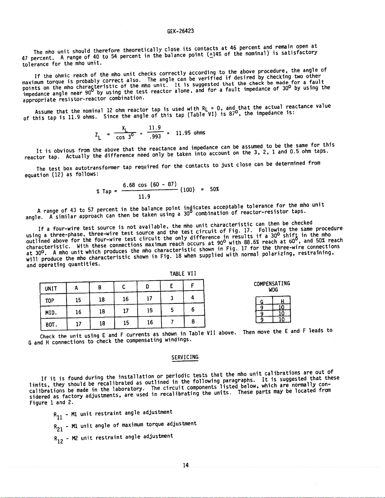
The
percent.
47
tolerance
the
If
maximum
points
on
impedance
appropriate
Assume
this
of
It
reactor
The
equation
A
range
angle.
If
using
outlined
characteristic.
3Q0
at
produce
will
operating
and
Check
and
G
unit
ruho
A
for
ohmic
torque
the
angle
resistor-reactor
that
is
tap
is
obvious
tap.
test
(12)
similar
A
four-wire
a
three-phase,
a
above
mho
A
UNIT
TOP
MID.
BOT.
the
connections
H
should
range
mho
the
reach
probably
is
chara8teristic
iiiho
near
the
11.9
from
Actually
autotransforrner
box
follows:
as
43
of
for
With
unit
mho
the
quantities.
A
15
16
17
unit
therefore
40
of
unit.
of
90
nominal
ohms.
the
the
57
to
approach
test
three-wire
four-wire
the
these
which
characteristic
using
to
to
the
correct
using
by
12
Since
=
above
difference
Tap
%
percent
can
source
produces
B
18
18
18
and
E
check
theoretically
54
percent
unit
rnho
also.
the
of
the
combination.
reactor
ohm
angle
the
X
1
30
cos
that
tap
6.68
=
the
in
be
then
not
is
test
test
connections
the
shown
C
16
17
15
currents
F
compensating
the
in
checks
The
niho
test
11.9
the
need
required
cos
11.9
balance
taken
available,
source
circuit
maximum
mho
D
17
15
16
GEK-
close
balance
the
correctly
angle
unit.
reactor
is
tap
this
of
=
993
reactance
be
only
for
87)
-
(60
point
using
the
and
the
reach
characteristic
Fig.
in
TABLE
shown
as
windings.
used
the
the
E
3
5
7
26423
its
can
It
alone,
tap
11.95
and
taken
(100)
a
test
only
18
in
contacts
point
according
verified
be
suggested
is
and
with
(Table
ohms
impedance
into
contacts
indicates
3Q0
combination
unit
mho
circuit
difference
occurs
when
VII
F
4
6
8
Table
(+14
for
=
RL
VI)
account
to
50%
=
acceptable
characteristic
at
shown
supplied
J
VII
at
of
to
that
a
0,
is
can
just
of
in
9Q0
in
above.
46
the
if
fault
and
87°,
Fig.
with
Fig.
with
percent
the
desired
the
that
be
on
close
of
results
and
nominal)
procedure,
above
check
by
checking
be
impedance
actual
the
impedance
the
3,
can
to
2,
be
assumed
the
tolerance
reactor-resistor
then
can
Following
17.
88.6w
17
normal
if
for
a
reach
the
polarizing,
COMPENSATING
WDG
L
9
1.9
move
Then
remain
satisfactory
is
made
3Q0
of
reactance
is:
the
be
and
1
determined
for
be
shif
30°
at
three-wire
H
10
10
10
E
the
open
the
two
for
by
same
0.5
the
taps.
checked
the
,
60
restraining,
and
at
angle
other
fault
a
using
for
taps.
ohm
from
unit
mho
same
the
in
and
connections
leads
F
of
the
value
this
procedure
mho
reach
50%
to
it
If
limits,
calibrations
sidered
Figure
1
they
as
and
is
factory
-
-
-
found
should
made
be
2.
Ml
Ml
M2
during
recalibrated
be
in
adjustments,
restraint
unit
angle
unit
restraint
unit
the
the
installation
laboratory.
are
angle
maximum
of
angle
outlined
as
used
adjustment
torque
adjustment
or
circuit
The
recalibrating
in
SERVICING
periodic
the
in
adjustment
14
tests
following
components
the
that
units.
mho
the
paragraphs.
listed
These
unit
below,
calibrations
It
which
parts
suggested
is
are
may
normally
located
be
are
that
out
of
these
con
from
Page 15

R
22
GEK-26423
unit
M2
-
angle
maximum
of
torque
adjustment
R
13
R
23
NOTE:
up
mounted
Before
for
approximately
in
RESTRAiNT
The
phase
resistors
angle
properly
Remove
1,
2.
Adjust
relay
3.
Connect
side
tween
4.
Connect
side.
contacts.
Connect
5.
side.
contacts.
-
M3
-
M3
making
upright
CIRCUIT
of
adjust
of
unit
unit
position
ANGLE
R11-R1-R
13
the
polarizing
R11-R12-R
13
lower
control
is
de-energized.
studs
the
the
two
studs
Adjust
stud
Adjust
restraint
angle
pickup
15
minutes
ADJUSTMENT
connection
spring
and
15
70
volt
stationary
and
16
until
R
12
and
15
R13until
of
maximum
phase
or
that
so
are
circuit.
the
so
16
test
17
17
angle
energized
the
used
following
plug.
that
one
to
source.
contacts.
to
one
moving
the
to
one
the
moving
adjustment
torque
angle
with
units
make
to
This
is
the
contacts
side
Adjust
side
side
adjustment
adjustments
rated
level.
are
the
is
done
required.
of
70
a
R11until
of
the
contact
the
of
70
contact
voltage.
phase
to
float
volt
70
of
volt
of
on
improve
volt
the
the
the
angle
between
test
the
test
middle
test
bottom
mho
Also
of
the
the
source.
moving
source
unit
source
unit
units,
it
the
transient
is
restraint
two
Connect
contact
and
floats
and
floats
unit
the
important
performance of
stationary
studs
on
studs
between
studs
between
should
circuit
the
15
and
16
be
the
that
the
contacts,
and
17
top
unit
and
18
the
18
the
to
two
to
two
allowed
relay
same
the
when
to
18
floats
the
stationary
the
stationary
be
as
unit.
the
the
other
other
to
the
heat
To
other
be
DIRECTIONAL
inner
Fig.
The
the
mho
stator
clockwise
within
12).
TORQUE
maximum
E
2
is
outside
units
the
(slightly
closed
(See
MAXIMUM
with
torque
for
mho
the
If
PICKUP
The
pickup
angle
the
at
in
equal
to
angle
CLUTCH
cup
placed
tightening
restraint
the
the
angle
area
the
of
the
ADJUSTMEN1
clutch
The
assembly
between
the
CHARACTERISTIC
fails
unit
or
specified
to
must
core
counterclockwise
or
currents),
ANGLE
taps
Ml,
or
of
the
of
restraint
of
must
the
self
torque
maximum
of
angle
disconnected,
of
limits
and
M2
ohmic
M3
reach
torque
circuits
polarizing
the
voltage
circuit,
unit
each
held
be
front
coils
locking
(Ru,
securely
perform
readjusted.
be
the
of
outlined
as
it
can
respectively.
of
each
checked,
as
Rl2,
circuit.
triangle.
they
should
and
(3/8
nut
properly
as
the
with
mho—type
restored
be
unit
and
Therefore,
must
when
slip
a
with
contact
the
inch)
at
This
required
special
units
ACCEPTANCE
in
should
ACCEPTANCE
in
are
R13)
This
be
not
a
special
the
at
high
by
is
since
used
force
head.
can
to
core
can
means
within
be
used
done
of
wrench
top
current
be
accomplished
make
adjusting
checked
be
TESTS.
of
TESTS.
to
adjust
so
the
adjust
to
45-65
0246A7916
clutch
The
the
of
levels
sure
adjustable
the
+14
that
resistors
grams
cup
that
wrench.
using
If
percent
the
On
the
restraint
the
reach.
is
(1/2
pressure
shaft.
as
it
angle
R11,
by
the
is
applied
outline
means
contacts
(Cat.
connections
found
resistors,
published
the
of
CEYG51A
of
the
torque
and
R
12
to
wrench,
inch
varied
is
under
of
No.
that
the
restraint
R
13
the
rotating
close
shown
the
R21,
adjustable
will
1/32
by
ACCEPTANCE
core
the
and
remain
0178A9455
angle
Pt.
in
Fig.
of
and
R22.
minimum
resistors
circuit
are
moving
used
inch
to
contact.
thick)
proportional
be
loosening
TESTS
1)
10,
maximum
R
23
reach
to
the
set
or
but
The
15
Page 16

GEK-26423
is
It
replacerrient
When
quantity
was
relay
recommended
any
of
ordering
required,
furnished.
that
that
renewal
name
are
of
sufficient
worn,
parts,
the
part
broken,
address
wanted,
quantities
or
the
RENEWAL
of
damaged.
nearest
give
arid
PARTS
renewal
Sales
the
parts
Office
General
carried
be
of
Electric
the
in
General
Requisition
stock
Electric
enable
to
number
Company,
on
the
which
prompt
specify
the
16
Page 17

GEK-26423
The
sion
current
used,
parallel
the
This
the
ZERO
NO
the
CEYG5IA
accurately
line
compensation
only
the
line.
CEYG51A
is
because
protected
SEQUENCE
zero
When
faulted
where:
remaining
relay
line.
sequence
phase
will
relay
on
is
factors
These
must
reversal
CURRENT
a
for
measure
three
phase
used,
NOT
its
variation
will
be
mutual
compensated
in
not
COMPENSATION
current
single
z
Z’
+
1
compensation
phase
(Z0’
2C+C
Positive
=
Zero
=
MINIMUM
positive
faults.
reach
unit
in
evident
be
parallel
the
ground
to
-
Z1)C
0
o
sequence
sequence
APPENDIX
PERMISSIBLE
FOR
THE
sequence
However,
is
foreshortened.
reach
will
from
the
for
zero
line
NOT
is
fault
ZI’
I
impedance
impedance
I
REACH
CEYG51A
impedance
single
on
due
be
the
following
sequence
could
used,
the
at
a
of
the
SETTING
to
cause
effective
far
of
the
and,
therefore,
phase
If
zero
zero
equations
mutual
the
end
of
the
protected
protected
ground
to
sequence
sequence
impedance
who
unit
impedance
the
line.
Ta
line
distance
faults,
current
mutual
and
to
is:
line.
lb
due
operate
as
seen
Ia
on
the
when
compensation
impedance
mho
The
parallel
a
to
incorrectly
by
zero
the
transmis
sequence
with
units
line.
relay
is
a
of
on
on
cent
To
tap
insure
setting
that
permissible
the
z
I
0
‘a’
C
C
0
T
K
0
relay
T
and
as
positive
direction
bus,
line
as
the
the
when
current
the
maximum
per
at
the
I’/l.
protected
taken
same
voltage.
the
remote
in
relay.
impedance
the
constant
basic
basic
basic
for
up
parallel
line
minimum
minimum
minimum
lags
m
parallel
=
Zero
“
current
in
=
Phase
=
Positive
Zero
=
Tap
=
Design
=
The
=
the
on
sequence
the
A
sequence
setting
100
200
300
aigle
faulted
line.
flow
protected
current
sequence
in
Constant
the
for
for
the
the
for
the
phase
in
sequence
zero
Total
=
mutual
current
the
parallel
line.
in
the
distribution
distribution
percent.
1.0
ohm
2.0
ohm
3.0
ohm
fault
current
picks
is
constant
the
fault
a
between
line,
in
10/10.
tap
tap
tap
fault
is:
(600_U)
=
KCos
1.25
r
L
z1)C
2C
0
-
C
0
÷
(Z0’
Z
1
+
ZI”
+
Ta
1
I
lb
17
Page 18

the
relay
zero.
last
parallel
based
WITH
faulted
the
If
shortest
factor
The
beyond
If
there
If
term
Note
All
on
ZERO
When
solution
reach
the
is
there
becomes:
in
that
circuits
voltages,
CT
the
SEQUENCE
sequence
zero
for
pase
1.25
far
no
is
this
and
equation
to
setting
introducted
bus,
sequence
zero
mutual
summation,
be
must
currents
PT
ratios
CURRENT
current
single
a
yields
lb
in
tap
(100
equation
settings
possible
lower
mutual
z
the
om
existing
i
0
direction
impedance
considered.
impedances
and
the
of
protected
COMPENSATION
compensation
ground
to
phase
I
Z
tap
a
percent
lb
is
will
impedance,
between
the
in
is
fault
GEK-26423
CT)
value
will
tap)
safety
a
required.
be
the
the
zero
the
of
above
line.
used,
This
the
the
at
greater
suffice.
factor.
term
last
protected
sequence
equations
applies
effective
far
end
than
In
the
in
line
are
to
impedance
the
of
100
order
denominator
and
current
interins
I
line
percent,
several
flow
well
as
extend
to
(I
secondary
of
as
seen
as
becomes:
this
of
other
“)
0
implies
the
equation
in
by
the
reach
circuits,
each
quantities
relay
that
of
lb
of
even
the
becomes
this
the
the
on
where:
To
percent
Under
direction
result
can
them
insure
from
tap
that
setting
some
that
a
in
picking
system
one
false
up
K’
relay
the
permissible
—
conditions
the
or
trip,
reverse
on
T
T
+
xo’
on
=
1.25
MAXIMUM
other
is
it
K
=
K
5
=
+
-
3X1’
the
is:
r
LZ
1
’
NO
it
of
necessary
faults.
(C
z°
(C
0
3K’
Xl’
faulted
is
the
1
1
10’
phase
(60-0)
KCos
Z0I0”
+
1
a’
+
APPENDIX
PERMISSIBLE
SEQUENCE
ZERO
possible
associated
units
limit
to
Equations
C)
-
C)
-
Cos
Cos
(150—A-9)
(A-0-30)
The
used
picks
3K’I’
REACH
during
ha
unit
per
compensation.
for
for
up
II
SETTING
CURRENT
single
with
reach
the
and
zero
of
ritIo
at
fault
a
CEYG51A
THE
FOR
COMPENSATION
ground
to
phase
unfaulted
Jib
the
setting
give
of
this
the
phase
the
limit.
sequence
remote
faults
will
starting
Ha
JIb
current
bus,
in
pick
units
the
non-tripping
the
up.
be
to
maximum
Since
prevent
to
this
18
Page 19

The
the
non-tripping
The
non-tripping
Under
direction
necessary
ground
to
system
system
some
that
to
faults.
constants
direction
constants
direction
system
the
limit
T
C
C
0
Z
0
9
K
5
A
at
conditions
unit
on
the
reach
Equation
T
in
in
at
=
=
=
=
=
=
=
=
the
the
=
the
the
Minimum
Positive
Zero
System
System
The
Constant
Angle
these
relay
unfaulted
setting
JIc
gives
K
3Z
0
above
relay
sequence
angle
depending
equations
terminals.
it
(C
-
equations
terminals.
permissible
sequence
positive
zero
of
depending
is
possible
phase
the
of
this
C)
Cos
distribution
sequence
sequence
the
system
on
should
will
units
limit.
(9
GEK-
264
should
This
tap
setting
distribution
impedance
positive
on
the
the
ratio
be
evaluated
This
fault
during
pick
to
prevent
-
60)
23
be
evaluated
fault
constant
constant
impedance
as
ratio
of
location
double
up.
them
location
in
percent.
as
viewed
sequence
of
Z0/Z1.
ZQ/Z
1
.
for
phase
Since
from
for
I0’/IO•
viewed
See
single
a
is
to
this
a
single
is
designated
I’/I.
from
from
impedance
See
curves
designated
ground
can
picking
the
curves
phase
faults
result
the
fault.
up
phase
Z1.
on
to
as
on
to
as
fault.
on
Figure
Figure
ground
Fl
in
in
a
reverse
Fl
in
the
false
ground
14.
Figure
fault
in
Figure
14.
fault
in
5.
non-tripping
trip,
double
lic
5.
the
it
phase
in
is
where:
All
Note
After
three
added
lay
at
equations
on
the
Aside
All
based
The
other
that
the
values
to
this
the
is
minimum
from
voltages,
on
the
effects
terms
C
0
values
should
setting.
terminal
negative,
permissible
all
CT
and
currents
and
of
are
be
under
of
PT
arc
K
9
defined
C
in
T
of
selected
This
that
the
ratios
resistance
=
Design
=
The
angle
above.
equation
have
been
and
value
of
consideration.
signifies
tap
setting.
above,
and
of
the
impedances
the
have
Constant
for
100
for
200
300
for
of
tIc
have
calculated
then
tap
that
relay
protected
not
the
some
setting
If
the
should
in
been
1.0
2.0
3.0
the
margin,
any
the
basic
basic
basic
system
same
equations
for
is
(or
particular
never
above
line.
included
minimum
minimum
minimum
zero
values
such
then
all)
be
equations
in
tap
tap
tap
sequence
as
ha,
as
10:
the
minimum
of
the
equation
set
these
they
hib
(not
values
(or
on
a
are
calculations.
impedance
in
have
and
TIc
10
percentage
permissible
of
equations)
that
tap
terms
in
Z0.
equations
above,
T
calculated
is
of
the
points),
tap
offers
lower
secondary
ha
largest
setting
from
no
than
and
lIb.
should
for
the
limitation
10
percent.
quantities
of
the
three
the
be
re
19
Page 20

GE
K-2
6423
for
for
where:
IIb,
equation
Type
When
single
double
All
If
CFPGI6A.
zero
the
or
phase
phase
other
Ilic
Ic,
sequence
to
to
terms
minimum
above
then
current
ground
T
ground
=
T
K’
as
are
permissible
positive
are
will
it
MAXIMUM
WITH
compensation
faults
--
in
K
[(3K
S
[(3K
K
faults
K
L(3K’
—-—-——
—
Xo’
3X
1
defined
tap
necessary
be
PERMISSIBLE
SEQUENCE
ZERO
is
non-trip
the
C
1)
+
°
Zi
C
1)
+
Zi
non-trip
the
in
C
1)
+
3
Xl’
The
compensation.
Appendix
in
setting
greater
and
use
to
APPENDIX
REACH
used,
direction:
C)1
-
C)]
-
C)1
-
unt
per
II.
includiny
than
the
III
SETTING
CURRENT
equations
the
(15O—A--O)
Cos
(A-O-30)
Cos
direction:
(9
Cos
ratio
suitable
maximum
the
sequence
zero
CEYG51A
THE
FOR
COMPENSATION
Appendix
of
60)
-
sequence
zero
of
margins
permissible
directional
determined
as
II
lIla
current
setting
tap
overcurrerit
are
Ilib
IlIc
modified
be
to
from
as
supervising
as
for
used
equations
determined
follows:
THe,
from
relay,
Since
the
last
edition,
Figures
changed.
been
have
15
and
4
20
Page 21

n
GEK-26423
TARGET
SEAL—
UNIT
P11
P
21
P12
22
R
P13
IN
RESTRAINT
BLOCK
TAP
Ml
UNIT
M2
UNIT
P23
FIG.
(8039015)
1
RELAY
TYPE
CEYGS1A
21
OUT
OF
CASE
(3/4
FRONT
M3
VIEW)
UNIT
Page 22

GEK-2642
3
FIG.
(8043301)
2
RELAY
TYPE
CEYG51A
22
OUT
OF
CASE
(3/4
REAR
VIEW)
Page 23

GE
K-2
6423
11
13
15
17
19
Ml
B
I
Mi=TOP
UN
T
M2=VIDDLEUNIT
[!3=SOTTOM
FIG.
U\
3
(0178A9106-1)
M2
2
4
6
M3
8
SHORTINOER
T
INTERNAL
CONNECTIONS
DIAGRAM FOR
23
THE
CEYG51A
RELAY
Page 24

()
I
-
4
SS3
JIJPES
c4XbA6cThfrN
ITLINE
O17SA73
CVICES
Of
INTERNAL
0178A9106
TABULATION
DEVICE
Lco5i
[
EXT.
NO
ELAY.
I%SIDT
MArE.
CArE
RE
ARE
7
8
1:’D_LD
1—6209272
46A891
0207A5.465
O127S944
367M26G—2
I
CFPGIE4
I
[x
[7266G—2
03
:i
5T
a
S
Cr
C,C%ECT
POLAR7A’ON
USED,
DCCLV.
IS
0
TO
POTENTIAL
C
IF
0.
POLARIZATION
CONNECT
TO
USED,
A
C
POTENTIAL
NOT
TO
IS
IF
A
8
3
STuDS
TO
-
--
Ci’%[CTED
N’-EN
IA
AX.
S’OA..
E7EAE
CCCCS.
flE
LEAVE
USE
AUX.
USSO.
EXT.
NOT
IS
PO.ARI2ATI3N
CONCCS.TOS2Sj4...__
EXJ.
CURRENT
POLAPIZA
T
IO+I
USING
OJPRENT
..UTI4AJ(E
I
G-.2
ON
TRIPPING
TNA?4SEERPED
DIRECTI(AL
AUXILIARIES
CEYG
1L
3
r
0
aaa
CAPCTIER
201
FOR
STARTING
CARRIER
REXEPSED)
FOR
A€t
USED
sNXO4r%AT1
*IEN
RNRW
Z
TEi:(.FpT,,
STUDS
CEY.
TO
05 THE
CONWS.
9—10
REVERSE
7—A.
STARTINO.
V—4.
0
0.U,0
U’
C-.
-<
e
I
-I
0
C)
C-,
—I
m
-C,
a.,
0
C-,
-<
Page 25

GEK-26
423
138KV
Ft
I2MILES
F
H
MILES
30
J
MILES
36
138KV
‘-1
F2
FIG.
O2O8A5544-O)
5
TYPICAL
25
138KV
TRANSMISSION
SYSTEM
Page 26

BACK
GEK-26423
LL
c
(
L
)
(
C
J
T
L_JUL
FRONT
I
)
0
0
To
E
‘0
IN
K1
0
E
23
FIG.
(0208A5545-O)
6
TYPICAL
26
SCHEMATIC
OF
MHO
UNIT
Page 27

GEK-264?3
x
0
60
SHADED
M*J
AREA
UNIT
TRIPPING
IS
R
AREA.
FIG.
(0208A5543-O)
7
TYPICAL
27
R-X
DIAGRAM
OF
MHO
UNIT
Page 28

EK-2G423
A
C
1
A
B
Ec
FIG.
8
(0208A5541-O)
TYPICAL
RELATION
28
OF
I,
E’
3
AND
E’AN
Page 29

GEK-26423
1
M
3
M3
M2
M2
Ml
Ml
15
18
16
17
17
17
16
16
15
18
18
18
18
18
15
15
17
17
16
16
16
15
15
17
10
4
95
3
10
6
9
10
8
9
7
POLARITY
UNIT
TEST
67
2
VOLTS
3
FIG.
(0127A9562-1)
9
29
POLARITY
TEST
Page 30

GEK-2642
3
03
2
S
(±)
A
ER
FIG.
(0195A4970-O
10
Sh.
FIGURE
4)
TYPICAL
30
7
TEST
CONNECTIONS
B
C
D
DIAGRAM
Page 31

GEK-26423
CONNECTING
NOTE:
AFTER
BEFORE
PLUG
ENGAGING
ENGAGING
AUXILIARY
AUXILIARY
MAIN
THE
MAIN
BRUSH
BRUSH
BRUSH
BRUSH
CONNECTING
TERMINAL
THE
ON
CONNECTING
SHORTING
PLUG
TRAVELS
BLOCK.
1
‘L..
BAR
BLOCK
—
1/4
INCH
FIG.
11
(8025039)
CROSS
SECTION
DRAWOUT
CASE
31
SHOWING
POISITION
OF
AUXILIARY
BRUSH
Page 32

INNER
A.
MAGNET
B.
WAVE
C.
OCTAGON
0.
FLAT
E.
CORE
F.
SIATOR
COILS
A
WASHERS
[OR
NOT
WASHIER
DOWN
HOLD
OR
CORE
CORE
(HEXAGON)
NUT
GEK-26423
ADJUSTMENT
FIG.
(0208A3583-O)
12
32
ADJUSTMFNT
CORE
D
Page 33

GEK-26423
4.0
3.5
3.0
tI)
cf)
.5
u2
.0
z
Lii
F-
3n.
TAP
2.R-TAP
JLTAP
I
0.5
1.5
1.0
.
5
0
0
15
15
30
10
15
22.5
45
15
ac
30
60
37.5
75
45
90
AMPERES
FIG.
13A
(0273A9031-O)
TYPICAL
TIME-CURRENT
ZERO
CHARACTERISTIC
PERCENT
COMPENSATION
33
WHEN
TYPE
CEYG51AISUSED
WITH
Page 34

GEK-26423
4.0
3.5
3.0
U)
U)
0
LI)
UI
-J
L)
>-
o2.O
z
U)
I—
1.5
1.0
0.5
3ftTAP
2-fl-TAP
IJLTAP
FIG.
(o273Ago3o-o)
138
0
0
0
5
7.5
15
I0
IS
30
15
45
20
30
60
25
37.5
75
30
45
90
AMPERES
WITH
USED
TYPICAL
TIME-CURRENT
PERCENT
50
CHARAc.TERISTIC
WHEN
COMPENSATION
34
TYPE
CEYG5IA
IS
Page 35

GEK-?6423
cc
3:)
if)
J)
3fTAP
21L
IJLTP
Lr
w
-J
w
1—
TAP
a
.c
.5
30
10
15
5
22.5
45
20
3D
60
25
37.5
75
0
C
0
5
7.5
‘5
3D
45
9)
AMPERES
FIG.
13C
(o273A9o2g-o)
TYPICAL
TIME-CURRENT
100
CHARACTERISTIC
PERCENT
COMPENSATION
35
WHEN
TYPE
CEYG51A
IS
USED
WITH
Page 36

ZQ/’Z
1
VS.
A
AND
K
5
OF
CEYG5IA
EVALUATION
F.M.F:
TITLE:
NJ
-I
-n
CD
c-c-c
CD
c-fl
c-c,
CD
C
-
—
C
0-c
c.j
CD
U,
NJ
CD
Page 37

3EK-26423
20
5IGMM
1/4
6
312
DRILL
HOLES
7.
198MM
SEMI-FLUSH
b
G8MM
I
GLASS
791
1
——
—
.125
29MM
_I_
MiD.
—
PANEL
LOCATION
SURFACE
MI
/16—16
URFACE
2917151311
STUDS
MTCj,
0QQQ
000Q
20
18
16
14
12
6)
MID.
10—32
SCREWS
X
3/8
STUD
NUMBERING
9753t
0QOQ
0000o
10
S
6
4
2
BACK
CUTOUTS
DRILLED
—
4
MAY
VIEW
REPLACE
1-IOLES
15,562
39GMM
5MM
FOR
TYPICAL
INCHES
PANEL
SEMI-FLUSH
FRONT
DIM.
MM
FIG.
15
I
CU
DRILLING
VIEW
(0178A7336
TbU
T
MOUNTING
VIEW
FOR
[5])
OUTLINE
CSE
SHOWING
SURFACE
AND
ASSEMBLY
MTG.
PANEL
DRILLING
M
ON
5/16—18
OF
HARDWARE
STEEL
DIMENSIONS
1
33MM
PANELS
FOR
FOR
STUD
THE
PANEL
SURFACE
FRONT
CEYG51A
500
12MM
(TYPICAL)
DRILLING
MOUNTING
VIEW
RELAY
37
Page 38

1
OA
20V
30
LOAD
GEK-26423
BOX
3
-
TEST
WIRE
3
STARTING
CIRCUIT
UNIT
ØB
A
TA
f
H
F
G
(COMPENSATING
WINDING)
D
C
5’:?
CENTER
VARIAC
TAPPED
-
5
RATED
AMPERES
20
STARTING
UNIT
TEST
WIRE
4
-
3
TRANSFORMER
AUTO
KVA
CIRCUIT
10%
A
B
N
E
(COMPENSATING
G
CIRCUITS
FOR
CEYG51A
WOG)
RELAYS
FIG.
SEE
(0227A7005-Q)
16
D
TABLE
FOR
VII
SCHEMATIC
F
H
CONNECTIONS
STUD
DIAGRAM
OF
38
TEST
1%
Page 39

GEK-26423
0
0
0
XL
RL
CONNECTIONS
SEE
*
-
CENTER
**
-
VAPIAC,
FIG.
(0227A7004-2)
17
TABLE
SHOWN
VII
FOR
TAPPED,
RATED
TEST
FOR
OTHER
KVA
S
AT
20
CIRCUIT
TOP
UNIT
UNITS.
AUTO
TPANSFOR1ER
AMPERES
FOR
3
PHASE,
FIELD
A
TESTING
3
WIRE
39
THE
TEST
STARTING
SOURCE
UNITS
OF
THE
CEYG51A
RELAY
R
USING
Page 40

ØB
øC
GEK-26423
XL
RL
(8/93)
CONNECTIONS
CHECK
AND
FIG.
(600)
TABLE
BOTTOM
18
(0227A7006-2)
GENERAL
SHOWN
VI
FOR
UNITS.
TEST
FOR TOP
MIDDLE
CIRCUIT
ELECTRIC
UNIT.
SW.
CHARACTER
FOR
FIELD
A
3
PHASE,4WIRE
PROTECTION
TESTING
tMO
AND
I
STI
C
THE
STARTING
TEST
SOURCE
CONTROL
UNITS
BUSINESS
OF
THE
DEPT.,
CEYGS1A
RELAY
MALVERN,
USING
PA
19355
 Loading...