

Page 1
INSTRUCTION
S
GEK—45495
U
MHO
DISTANCE
TYPE
RELAY
CEY52B
GENERALS
ELECTRIC
Page 2
LsURJPTION
APF’L
(Al
I
I
ON
RATINGS
OPERATING
PRINCIPLES
CHARACT[RISEILS
BURDENS
LALCULA1
UONSTRUCT
RECEIVING,
ACLEPTANCE
ASTALLATION
iON
OF
ION
HANDLING
TESTS
PROCEDURE
INSPECTION
PLRIODIC
CHECKS
SERVICING
RENEWAL
PARTS
SETTINGS
AND
AND
ROUTINE
STORAGE
MAINTENANCE
GE
K-A
5495
CONTENTS
PAGE
3
3
2
4
5
7
7
N
8
9
11
14
14
15
17
‘S.)
to
C-)
CD
to
to
“S
Page 3
GE
K-4
54
95
The
designed
is
relay
testing.
dimensions
is
relay
not
been
The
itself,
relays
may
they
protection.
distance
When
that
tap
highest
Since
fault,
a
voltage
protection
The
CEYS2B
section
the
than
less
The
cycles
t
desired
the
back
A-B
as
adjust-nd
means
by
evuuj
u’ctfte’L
the
pu’tcha.ea’-
hIlt
,‘to
CEY52B
specifically
constructed
The
not
limited
C[Y52B
but
may
be
scheme
applying
will
possible
the
at
section
in
type
rating.
will
basic
of
determine
in
of
Thnie
sA6e
po
-ui1jo’tnri..tLon
Io
the
ucJi
relay
interndl
shown
are
intended
in
relay
rather
used
be
as
used
Figure
with
acconinodate
level
memory
the
relay
relay.
the
this
for
under
typical
a
entitled
percent.
25
CEY52
The
noted
be
minimum
relay
the
the
percent
one
autotransformer
utcton
con.tA,nqenc.y
pwtpoe,
oxteiit
asu.’utnce
three-phase,
is
a
use
for
three
of
connections
Figure
in
for
use
respect.
this
BASIC
TAPS
0.5
1.0
is
a
is
designed
a
step-distance
in
of
part
illustrates
4
CEX2OB
the
relay
this
the
of
torque.
action
should
not
The
contingency
CALCULATION
application.
TAPPED
covered
relay
minimum
basic
that
reach
(see
basic
steps
do
bi
de’u’,d
.‘LequL’ted
guJen
..a
MHO
TYPE
DESCRIPTION
speed,
high
the
with
single—phase
for
Typical
16.
first
a
as
MINIMUM
CEY52R
OF
-
1.0
—
-
2.0
-
three—phase,
to
be
high-speed
a
typical
CEX2OA
the
REACH
1.5
3.0
used
scheme
or
units
relay
external
function,
zone
single
with
to
pilot-relaying
external
relay.
the
the
relied
is
protection
reach
CLY52B
should
required.
SETTINGS
OF
Once
the
on
setting.
will
provide
to
be
settings
for
desired
of
be
protection
AUTO—TRANSFORMERS.
instructions
these
three
setting
Fig.
minimum
over
tap
pu.’tpo-’t-t
no.t
be
to
o.’
rnattc’t
the
the
w-tk
by
reach
basic
for
2).
setting
a
leads
met
I-touLd
p’wduc.ta
The
4/1
UL
hou.fd
‘tc.apee.t
and
minimum
each
position
range
the
on
eovciz.
-to
connec,tcon
pa.’ct
dci.eailied
adjustment
unit
of
the
tap
be
to
DiSTANCE
CEY52B
single-zone
CEX2OB
mounted
shown
are
connections
TABLE
ICATION
APPL
mho
zone
CEX2OA
a
provide
connections
given
a
of
This
be
only
supplemented
provides
have
Under
RATINGS
settings
reach
made
is
the
of
mho
any
for
blocks
detaiJs
aU
wLth
pitobfms
cithvi.
e1eived
eke4n
eode4
tocitf
RELAY
reactance
one
in
in
the
thus
I
distance
CEX208
or
zones
two
scheme
circuit,
will
effective
time-delay
worked
a
been
conditions,
no
available
is
ranges
by
two
units.
of
the
the
at
n-taitiou,
thc
to
rnec’-t
azid
directional
type
L2—D
Figure
to
transient,
SELECT
relay
in
to
insure
protection
other
by
example
calculated,
the
of
are
means
sets
The
basic
right
0L
aJLe
(cvtc’uct
appcaIit’e
icknanet’
relay.
case
10,
the
CEX
CEX2OA
CEX2OR
that
reactance
protection
of
addition
relay
the
select
that
several
for
devices
should
for
inho
listed
of
links
links,
of
ohmic
minimum
side
ope’Litu)e
wh{cJ!
with
while
relay
overreach
SHOWN
for
the
120
units
for
reach
of
aiz.C
distance
mho
See
provisions
outline
are
BELOW
is
not
type
providing
to
when
the
the
cycles
for
to
determining
taps
the
volts,
are
the
a
on
(for
of
reach
the
c2u.prnnnt
n
not
etsc
ANSI,
b1
cauc
Table
shown
characteristics
meant
relay.
against
is
it
highest
relay
after
fault
any
detect
are
restraint
5
given
mho
terminal
each
the
settings
relay.
miLtefltliIrc.
o’
cOvQYted
Conipanu.
1H
tlzoe
relay.
I.
for
panel
and
in
Figure
to
The
phase
step-distance
used
basic
operate
will
that
this
the
set
taps
amperes,
in
units.
board
unit),
inho
units
—--..____
no
IMA
a,id
oa-i
it
CEY52B
The
sirjle
drilling
used
be
combination
faults,
step-
a
in
minimum
inception
the
provides
condition
settings
described
as
ever
60
Table
Selection
located
each
can
listed
to
p4ovd
Lt?etif
ttz;
L’att’1.
WaS
phase
4.
The
have
by
or
at
be
50
or
II.
identified
be
Table
in
St(!Led
reach
the
zero
if
of
in
set
of
at
oi
OL
of
of
the
the
II
3
Page 4
BASIL
**MaxiIiluIli
CONTACTS
The
the
circuit
the
relay
REACH
-
1,0
0.5
1-2-3
*Adjustment
increase
contacts
breaker
contacts
TAPS
-
1.5
taps
torque
to
approximately
of
the
trip
have
are
angle
CEY52
circuit
no
interrupting
set
can
relay
BASIC
(ØN
using
be
120
must
MTN
OHMS)*
0.5
1.0
1.5
1
2
middle
adjusted
percent
will
be
rating.
REACH
close
opened
tap
up
of
and
by
GE
K-4
TABLE
r
at
the
to
75
its
carry
an
auxiliary
5495
II
RANGE
(0-N
OHMS)
0.5
-
1.0
-
1.5
-
1—4
2-8
3-
factory.
degrees.
reach
momentarily
at
2.0
4.0
6.0
The
the
switch
60
reach
degree
30
contact
ANGLE
MAX
TORQUE
600
600
60°
600
600
of
amperes
OF
**
**
**
**
**
the
setting.
direct
or
other
iriho
units
current.
suitable
ONE
RATING
150
150
150
150
150
will
SECOND
However,
means
since
TARGET
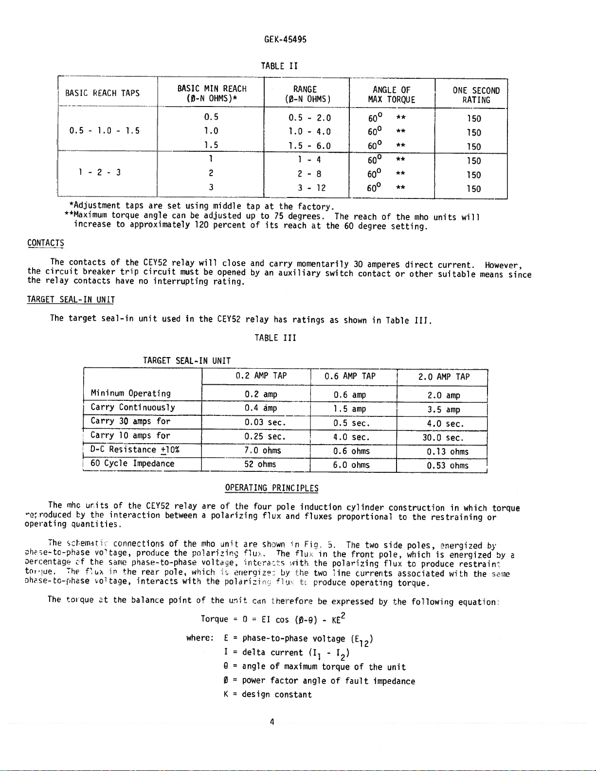
The
The
‘o:roduced
operating
The
se—tc-jhuse
Dr
entaq
tcr
we.
zhse-
to-phase
The
SEAL-IN
target
inum
nihc
units
ty
quantities.
sc[.emlii:
f
Th
Cl
torque
UNIT
Carry
Carry
Carry
0-C
60
the
c’
the
ux
ot
seal-in
Continuously
30
10
Resistance
Cycle
of
interaction
connections
tage,
5éiPi
in
the
taqe,
the
unit
TARGET
Operating
amps
amps
Impedance
the
CEY52
prodoce
priase
rear
interacts
balance
in
used
the
SEAL-IN
-
CEY52
UNIT
for
for
+lOt
relay
are
of
betweenapolarizing
of
-to-phasa
pole,
point
the
the
with
rho
gel
vo1tiçc
which
o
jr
arzinc
1.
the
the
relay
TABLE
0.2
AMP
0.2
amp
0.4
amp
0.03_=
0.25
7.0
ohms
52
ohms
OPERATING
the
four
flux
are
shown
t
iu
ntr
•nero1z:
nolan
wit
cc
car
has
ratings
III
TAP
sec.
PRINCIPLES
pole
induction
and
n
The
flu
s
iith
by
the
t
triereforo
i
fluxes
Fia
in
the
two
produce
.ne
as
0.6
0.6
1.5
0.5
4.0
0.6
6.0
.a.
the
polorizing
I
rxpr’.sed
shown
in
AMP
TAP
amp
amp
sec.
sec.
ohms
ohms
cylinder
proportional
Tue
two
front
currents
inc
operating
Table
—
construction
to
side
p010,
flux
associated
torque.
by
the
III.
0
2.0
3.5
4.0
30.0
0.13
0.53
the
poles,
which
produce
to
following
AMP
TAP
amp
amp
sec.
sec.
ohms
ohms
in
restraining
oneraized
is
energized
restrain
with
equation:
which
the
torque
or
by
by
seme
a
where:
Torque
=
0
E
phase-to—phase
I
=
delta
0
=
angle
=
power
0
K
=
design
El
of
factor
4
cos
current
maximum
constant
(0-9)
angle
-
voltage
1
torque
KE
2
(E12)
-
12)
of
the
unit
of
fault
impedance
Page 5
equation
GE
K—4
54
95
to
prove
that
the
reduces
equation
to:
defines
a
mho
characteristic
divide
both
sides
by
[2
and
transpo.e.
The
angle
MHO
UNIT
1.
setting
the
autotransformer
unit
through
unit
as
The
resulting
Ths
is
.
irec
Thus,
of
maximum
Impedance
The
impedance
at
by
means
the
expressed
angle
increase
shown
.iunal
the
Characteristic
maximum
a
of
origin
of
iy
unit
torque.
characteristic
the
and
by
where:
maximum
in
the
Action
will
torque
tap
links
the
reach
dotted
pick
Hence,
block
have
following:
2
njin
torque
up
at
the
of
angle
of
providing
on
the
rear
a
diameter
=
basic
of
to
approximately
characteristic
or:
a
a
60
the
constant
name
mho
degrees.
a
providing
along
Ohmic
mm.
mho
cos
(
Y
cos
(
component
mho
unit.
CHARACTER
unit
is
This
range
of
a
he
60
Reach
phase-to-neutral
unit
can
120
percent
in
Fig.6.
-
-
shown
up
total
degree
be
0)
B)
ISTICS
circle
to
tap
adjusted
of
K
K
of
admittance
in
Fig.
4/1
,
range
impedance
(lo0
setting
ohmic
its
can
or
of
z
reach
6
by
up
up
for
be
expanded
changing
to
line
()
reach
to
at
a
fixed
angle
depending
the
one
ohm
basic
by
means
the
12/1.
equal
of
75
degrees
at
60
The
the
degrees
basic
to
unit.
(see
of
minimum
circle
the
ohmic
SERVICING)
for
the
minimum
the
will
same
mho
reach
always
reach
reach
with
tap
on
taps
of
the
on
of
pass
the
setting.
the
:eri
tact:
shown.
‘tecessary
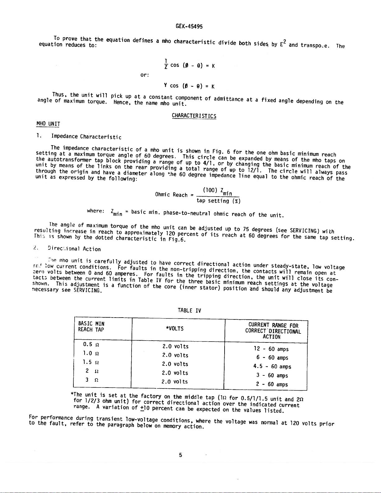
For
performance
to
the
low
volts
between
fault,
TihO
current
between
This
see
unit
is
conditions.
0
current
the
adjustment
SERVICING.
BASIC
REACH
1.0
1.5
2
*The
unit
for
1/2/3
range.
during
refer
to
carefully
and
60
is
MIN
TAP
i
is
ohm
A
variation
transient
the
adjusted
For
amperes.
limits
a
function
set
at
unit)
paragraph
faults
For
in
Table
of
the
factory
for
correct
of
+10
low-voltage
below
to
in
faults
IV
the
percent
on
have
correct
the
non-tripping
for
core
*VOLTS
2.0
vol
2.0
volts
2.0
volts
2.0
volts
volts
2.0
on
the
directional
can
conditions,
memory
in
the
the
(inner
TABLE
ts
middle
be
action.
three
IV
expected
where
directional
direction,
tripping
basic
stator)
tap
action
the
direction,
minimum
position
j_
(lii
over
on
voltage
action
under
the
contacts
the
reach
and
CURRENT
steady—state,
unit
settings
should
RANGE
CORRECTOIRECTIONAL
ACTION
12
-
60
6
-
60
4.5
-
60
3
—
60
2
-
60
for
the
0.5/1/1.5
the
indicated
values
was
unit
listed.
normal
will
will
any
amps
amps
amps
amps
amps
and
current
at
remain
close
at
the
adjustment
FOR
2
120
volts
low
open
its
voltage
prior
voltage
at
con
be
5
Page 6

3,
linderreach
t
LJICulat(d
miiInuI1
oi
,L:ing.
of
rig.
‘pHed.
hr
laul
4.
Memory
[he
polorizing
effective
be
nost
ri
ht
at
percent
zero
percent
the
memory
percent
The
cannot
is
delayed
application
depending
reduced
reach
liree
wirer
3
The
mis
t
dynamic
at
forcefully
time
of
action
tap
memory
be
relied
by
on
value.
settings.
dynamic
applied.
Action
flux
low
relay
its
of
setting
the
to
memory
voltaqe
This
ohmic
The
determined
curves
for
a
voltage
illustrated
bus
setting.
the
relay
is
will
action
on
if
zone
operate
action.
the
pullback
The
reach
itho
unit
curves
of
few
levels
and
Fig.
effective,
operate
will
the
2
setting
for
ohmic
unit
tap
will
by
tests
were
Fig.
cycles
therefore,
3
setting
close
tripping
nearby
value
or
reach
settings.
Operate
performed
obtained
illustrate
3
following
where
for
a
shows
regardless
Fig.
if
the
of
faults
reduction
it
zero
to
that
3
I3
contact
is
the
at
which
in
percent
Note
for
with
the
enables
voltage
protect
the
shows
is
greater
delayed.
type
and
all
with
the
who
of
that
for
RPM
there
GEK-45495
the
in
reach
of
that
points
no
full
effect
inception
the
fault
for
unit,
the
mho
than
only
When
relay,
will
niho
the
voltage
rated
who
this
tap
unit
the
unit
is
setting
fault
to
of
of
unit
by
under
setting.
1.6
a
short
the
be
shown
the
supplied
voltage
memory
the
referring
fault,
with
amperes.
relay
static
sufficient
will
is
plotted
current
right
fault.
to
operate
it
static
a
period
is
action
However,
three-ohm
operate
in
Fig.
against
scale
of
the
to
the
of
120
in
This
for
to
Fig.
is
imperative
conditions,
of
time
used,
as
characteristic
voltage
may
for
3
changes
volts
the
memory
low
3.
under
basic
a
be
curve.
relay
supplied
who
A
and
second
to
somewhat
the
1,
the
with
before
unit
action
fault
zero
that
will
dynamic
minimum
therefore,
should
give
lower
and
2
three—phase
the
The
steady-state
the
the
to
which
is
currents.
voltage
the
relay
not
see
conditions
reach
zone
relay
be
used.
tripping
than
3
ohm
fault
basic
fault
relay
maintains
particularly
This
fault
reach
fault
a
and
memory
and
without
the
basic
r,iniiuuw
curves
W.i
before
must
when
100
action
tripping
For
this
cur
the
can
be
zero
at
5.
Operating
The
setting
relay
fault.
rnho
TAPPED
operating
of
voltage
Time
taps
were
AUTO-TRANSOFRMERS
The
ohmic
auto-transformer
The
other
winding
The
necting
desired
the
subtracted
The
ale
tap
impedance
1:
neutral
:Xj
TAP
the
prior
curves
in
two
from
setting
SETTING
Time
time
unit,
the
reach
has
is
tap
windings
the
expressed
of
fault
to
the
are
given
100
of
the
two
windings.
tapped
setting
of
15-95
required
DESIRED
the
current
fault.
percent
(See
mho
at
the
percent
in
who
unit
magnitude,
The
for
four
position
Fig.
7)
units
may
One
percent,
0
is
made
by
auto-transformer.
winding.
to
protect
secondary
Tap
Setting
where:
=
91
is
curves
ratios
winding
the
a
terms,
0
9
determined
ratio
in
of
and
the
be
adjusted
1
percent,
proper
zone
(100)
=———
Power
Angle
Fig.
fault
angle
is
tapped
location
Note
Z
ohms
is
determined
(Mm.
factor
of
maximum
by
of
fault
8
impedance
by
percent
3
long,
a
are
of
means
in
that
Ohms
angle
number
impedance
for
the
maximum
of
10
percent
and
of
the
the
0—5
where
by
the
Setting)
of
fault
torque
of
to
torque
taps
5
leads
Z
of
factors
to
condition
relay
on
steps
percent.
marked
percent
is
positive
following
Cos
impedance
the
unit
relay
reach
was
the
winding
(—@)
such
as
reach,
of
rated
setting.
set
at
two
auto-transformers.
from
15
No.
1
may
phase
equation:
the
and
volts
60
degrees
percent
and
sequence
basic
magnitude
In
the
be
added
minimum
prior
all
lag.
to
jumper
phase-to-
to
cases,
95
or
reach
of
the
the
Each
percent.
con
cite
:xample
m,Nate
Set
Set
the
the
2:
one
4
TAP
one
4
end
percent
SETTING
end
percent
of
of
jumper
setting
DESIRED
jumper
setting
lead
of
lead
of
the
the
to
89
to
95
0—5
85
0-5
percent.
percent
percent.
percent
Set
winding
Set
winding
the
the
6
other
subtracts
other
adds
end
to
percent.
5
from
the
95
end
to
percent.
the
85
1
percent
to
percent
Set
setting.)
Set
No.
setting)
No.
1
to
1
percent.
1
to5percent.
Page 7
GEK-45495
BURDENS
CURRENT
CIRCUITS
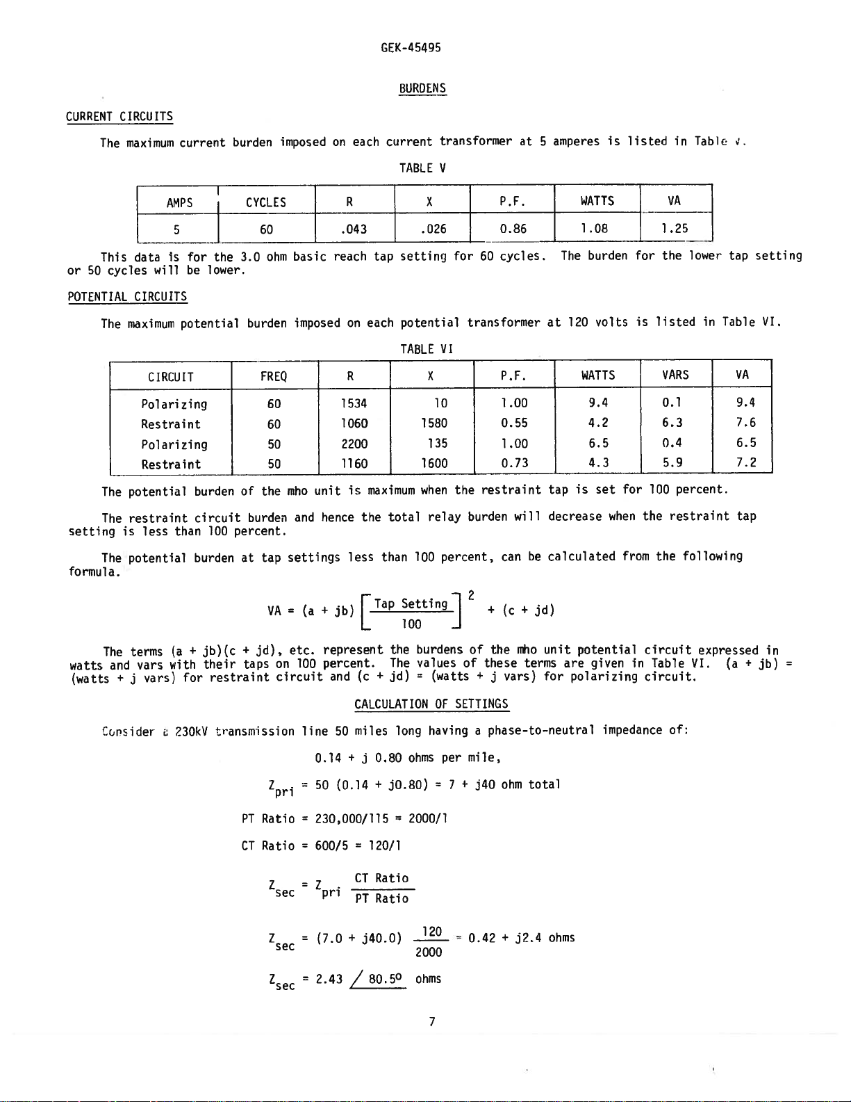
The
This
or
50
cycles
POTENTIAL
The
The
The
setting
maximum
data
will
CIRCUITS
maximum
CIRCUIT
Polarizing
Restraint
Polarizing
Restraint
potential
restraint
is
less
current
AMPS
5
is
for
be
potential
than
the
lower.
burden
circuit
100
burden
CYCLES
3.0
burden
of
burden
percent.
imposed
ohm
FREQ
60
60
50
50
the
basic
imposed
niho
and
unit
hence
on
R
.043
reach
on
R
1534
1060
2200
1160
each
each
is
maximum
the
current
tap
TABLE
setting
potential
TABLE
total
transformer
V
X
.026
VI
X
10
1580
35
1
1600
when
relay
for
60
transformer
restraint
the
burden
at
P.F.
0.86
cycles.
P.F.
1
.00
0.55
1.00
0.73
will
amperes
5
The
at
tap
decrease
WATTS
1.08
120
WATTS
is
is
burden
volts
9.4
4.2
6.5
4.3
set
when
listed
for
for
is
100
the
in
VA
1.25
the
lower
listed
VARS_—
0.1
6.3
0.4
5.9
percent.
restraint
Tah1€
in
.
tap
Table
VA
9.4
7.6
6.5
7.2
tap
setting
VI.
formula.
watts
(wattc
The
The
and
+
Tcride
potential
terms
vars
vars)
j
(a
with
230kv
burden
+
for
jb)(c
their
at
+
jd),
taps
restraint
transmission
PT
CT
tap
VA
Zpri
Ratio
Ratio
sec
z
settings
=
etc.
on
100
circuit
ec
+
jb)
(a
represent
percent.
and
line
50
0.14
=
50
(0.14
=
230,000/115
=
600/5
=
pri
=
than
less
rTap
L
(c
÷
Setting]
100
the
The
jd)
100
burdens
values
=
CALCULATION
long
miles
ohms
0.80
+
j
jO.80)
+
=
2000/1
=
120/1
CT
Ratio
PT
Ratio
+
j40.Q)
2000
(watts
OF
having
=
120
percent,
2
of
of
+
SETTINGS
a
nile,
per
7
+
j40
=
0.42
be
+
mho
terms
calculated
unit
are
for
+
the
these
j
can
(c
vars)
phase—to—neutral
ohm
total
j?.a
+
ohms
potential
given
polarizing
impedance
from
in
the
circuit
Table
circuit.
following
VI.
of:
expressed
(a
in
=
+
jb)
Zsec
=
2.43
80.5°
/
ohms
7
Page 8

GE
K-45495
Assume
is
it
this
For
given
The
both
at
case
the
connection
external
overlap
(see
brush
locking
leads
bottom
connections
cover,
mechanism
thick
insure
to
panel
the
drawn
‘abo1s
nagram
ito
a’
2.
minmJm
most
orotect
that
application
section
the
type
in
studs
plug
connections
circuit
the
when
contact
circuits.
relay
by
between
is
a
is
relay
appropriate
that
either
and
1
aid
tc
usea
in
Fip.
ralav
after
CEYS2
are
which
connections
mechanism
a
part
case
proper
replaced
icaludes
uesired,
*i
ends
Every
internal
make
The
terminated
and
which
The
and
separate
A
out
Pies.
The
wittrrisforrners
The
R23
The
he
hese
rio
ssed
reach
tap
removed
relays,
them
sub-a;seIHbly
in
car
blockS
against
CEY52
the
considering
the
under
relays
rear
the
made
and
in
connecting
as
at
the
guide
the
drawn
of
is
testing
from
2
show
identify
10.
settinq
oe
for
from
when
is
to
three-ohm
CHARACTERISTICS-
Percent
750
80.5°
are
external
for
inner
the
drawout
plug
Fig.
in
mounted
is
inner
the
at
respective
case
the
cover
can
plug
own
another
relay
the
=
Percent
Percent
assembled
block.
will
source
z
=
=
9
=
through
completes
the
indicated
pin
to
the
suitable
hardware
hardware
its
by
nircuit
similar
th’en
and
tap
includes
angle
tie
adjusted
from
changirg
to
case
its
included
not
damage.
Irnediately
used
be
effects
the
basic
3.54
stationary
circuits.
the
blocks
case
withdrawn
is
10)
Fig.
in
inasteel
back
blocks
by
assembly.
either
for
available.
is
be
which
removed
components
blocks
the
the
the
make
conjunction
in
of
minimum
TAPPED
Setting
Tap
Minimum
Setting
Tap
Setting
Tap
in
a
connections.
molded
have
an
has
on
and
with
9
cradle
This
of
the
of
thumbscrews,
semi—flush
included.
be
inserted
current
of
has
been
ro
are
suhassembi:
rho
mounted
i—pole
fOL
f
ma.’inlui
front
r;inioum
basic
the
settings.
RECEIVIND,
i
part
as
upon
with
infeed,
reach
CONSTRUCTION
deep
The
the
auxiliary
or
those
adequate
framework
case.
the
However,
in
place
and
its
the
to
setting
AUTO-TRANSFORMERS
(100)
=
Ohms
(100)
=
=
size,
large
electrical
The
and
inner
inserted.
is
cradle
holds
outer
terminals
circuits,
held
The
or
panel
blocks
brush,
pressure
called
connecting
and
the
surface
of
voltage,
tested
in
drawout
arie
Cienents
‘bc
or
back
or
the
inS
relay.
torce
of
reach
a
AND
control
of
HANDLING
of
receipt
a
set
(Mm.
3.0
(3.6)
outer
Some
firmly
case,
connecting
the
the
case
those
as
-‘
rrnostats
of
ne
STORAGE
panel,
relay,
a
CEX2OA
relay
the
should
ohms)
7
at
60
Cos
3.64
double-end
blocks
attached
for
the
shown
as
circuits
is
it
to
the
in
also
mounting
thickness
connecting
from
or
laboratory.
wth
which
mojntcd
the
ossoc
units
provide
to
to
used.
be
is
used.
Cos
deg.,
(80.5
connections
internal
in
especially
prevent
cradle
case
the
plug,
locks
plugs
must
plug
other
all
appear
on
cradle.
i
ated
,
811
are
will
examine
reach
(0—9)
3.6
75)
—
(L2D)
between
the
to
Fig.
are
the
and
besides
on
be
sources;
major
the
See
circuit
R2,
mounted
shipped
be
it
second
3.64
ohmic
The
75
at
drawout
between
which
case
connections.
to
9,
equipped
important
opening
isacomplete
latch
a
with
making
latch
the
in
place.
panels
all
indicated
test
to
components
the
an
front
Rj
05
cunipcnents.
used
813
on
in
any
for
/80.50
dog.
have
provide
the
or
of
the
zone
reach
case
the
nests
the
with
that
of
at
the
in
place.
The
up
on
relay
the
interncl
the
and
jr
back.
cartons
4
mage
protection
secondary
having
relay
a
studs
adequate
shorting
the
important
unit
both
electrical
target
two
to
the
relay
ider.ti
cradle
2
heostt.
settinj
sustained
equation,
units
removable
auxiliary
with
top
The
reset
inches
relay
in
place
ca
fiec
connection
ann
the
The
designed
studs
for
bars
inter
be
-
relay
and
ohms.
and
th’
all
and
order
on
a
basic
to
in
Page 9
GE
K-4
5495
transit.
transportation
Reasonable
or
the
adjustments
If
place
case
the
that
may
Immediately
no
damage
exwiination
ViSUAL
INSPECTION
Check
requisition.
Remove
of
physical
MECHANICAL
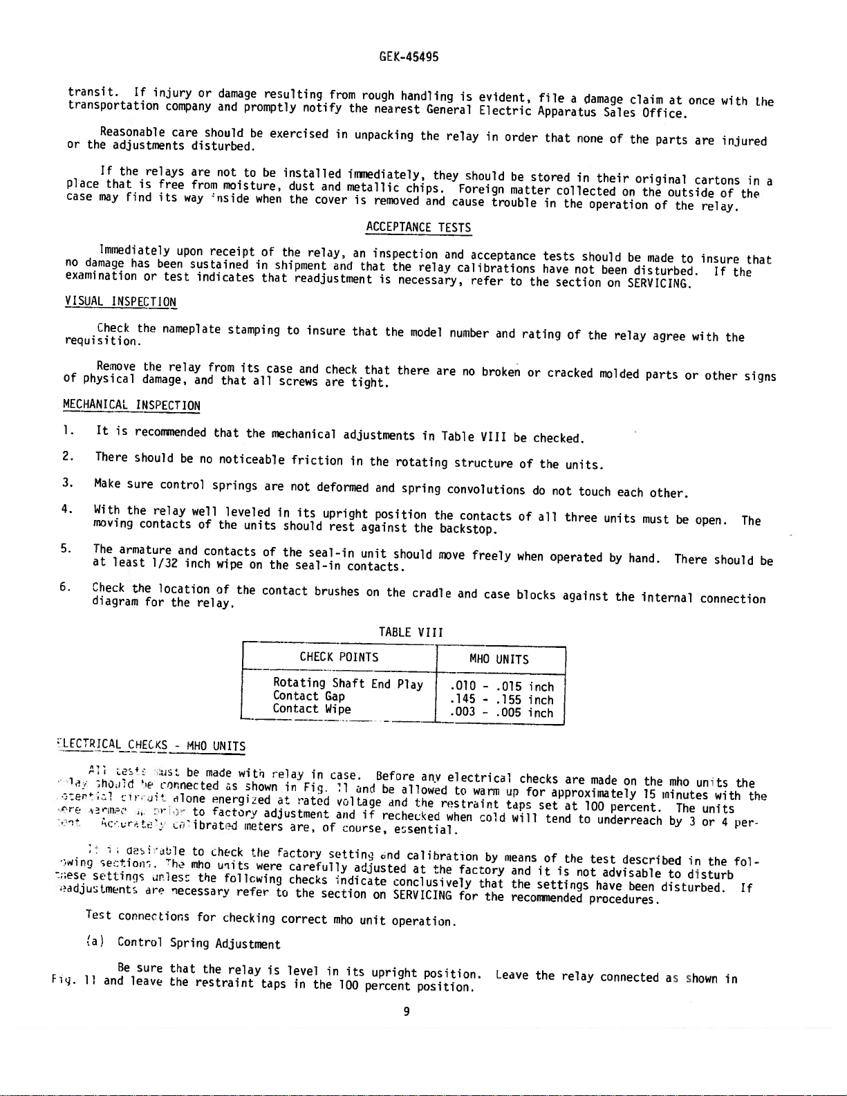
It
1.
2.
3.
4.
is
There
Make
With
moving
5.
The
armature
at
least
6.
Check
diagram
If
injury
company
care
relays
is
free
find
its
has
been
or
test
the
nameplate
the
relay
damage,
INSPECTION
recomended
should
sure
control
the
relay
contacts
1/32
the
location
for
the
or
disturbed.
are
from
way
upon
sustained
indicates
and
be
no
well
of
and
inch
relay.
damage
and
should
not
moisture,
nside
receipt
stamping
from
that
that
noticeable
springs
leveled
the
contacts
wipe
of
promptly
be
to
when
of
in
that
its
all
the
units
on
the
resulting
exercised
be
installed
dust
the
the
shipment
readjustment
to
case
screws
mechanical
friction
are
not
in
should
of
the
the
seal—in
contact
notify
relay,
insure
and
its
seal-in
from
in
and
cover
and
check
are
adjustments
deformed
upright
rest
brushes
rough
the
nearest
unpacking
ininediately,
metallic
is
removed
ACCEPTANCE
an
inspection
that
the
is
that
the
that
tight.
in
the
and
position
against
unit
should
contacts.
on
the
handling
General
the
chips.
and
relay
necessary,
model
there
in
rotating
spring
the
cradle
is
relay
they
should
Foreign
cause
TESTS
and
calibrations
number
are
no
Table
structure
convolutions
the
contacts
backstop.
move
and
evident,
Electric
in
order
be
matter
trouble
acceptance
refer
to
and
broken
VIII
freely
case
rating
or
be
of
of
when
blocks
file
Apparatus
that
stored
collected
in
tests
have
the
section
cracked
checked.
the
do
not
all
operated
a
damage
none
in
the
should
not
of
units.
touch
three
against
Sales
of
their
operation
been
on
the
relay
molded
each
units
by
the
claim
at
Office.
the
parts
original
on
the
outside
of
be
made
disturbed.
SERVICING.
agree
parts
other.
must
hand.
internal
once
the
to
or
be
There
with
are
injured
cartons
of
relay.
insure
If
with
the
other
open.
should
connection
the
in
the
that
signs
The
the
a
be
L[CRJCAL
1
a.•
s:er
1
•
r.r
rTJ-:’
wit-c
;ese
•idjtrnentc
Test
(a)
Fig.
11
sho
;etion-.
setiini
and
CHECKS
e:-
cernected
s’r
jt
.,.
r
ur
t.
r1ecs
re
connections
Control
Re
sure
leave
-
WHO
be
i1ane
or
to
ibratd
to
T
he
mho
necessarY
Spring
that
the
restraint
UNiTS
adde
energed
factory
check
uitc
the
follewing
for
checking
Adjustment
the
ss
relay
with
shown
meters
refer
Rotating
Contact
Contact
adjustment
the
were
to
is
taps
e1a
in
at
are,
fctory
carafully
checks
the
correct
level
in
CHECK
in
Fig.
rateu
of
section
the
POINTS
Shaft
Gap
Wipe
case.
l
vcltiqe
and
:ovrse,
sOttinU
indicate
mho
in
its
100
TABLE
End
Before
an•
be
if
rechecied
Lnd
adjusted
on
unit
upright
percent
VIII
Play
f
I
____
any
allowed
and
the
esential
calibration
at
the
conclusively
SERVICING
operation.
position.
position.
9
MHO
.010
.145
.003
electrical
to
restraint
when
factory
for
-
-
-
warm
col
by
that
the
UNITS
.015
inch
.155
inch
.005
inch
checks
op
for
taps
a
will
means
and
the
settings
recommended
Leave
the
are
approximately
set
at
tend
to
of
the
it
is
not
relay
made
on
100
percent.
underreach
test
described
advisable
have
procedures.
connected
been
the
15
disturbed.
mho
minutes
The
by
in
to
disturb
as
shown
3
units
units
or
the
with
4
the
the
per
fol
If
in
Page 10
voltage
the
angle
the
rent
should
value
to
across
dbout
occur
Use
shown
of
following
the
relay
in
Table
maximum
amperes.
two
between
voltage
torque
the
procedure
studs
for
IX
of
Gradually
currents
the
the
at
unit
unit.
listed
checking
in
120
volts,
being
Now
increase
in
reduce
Table
GEK-45495
each
set
tested,
current:
the
IX.
the
the
unit.
that
phase
vol
until
is
taqe
With
shifter
so
the
current
to
the
current
so
the
contacts
low
that
lags
test
set
the
voltage
voltage
of
the
amperes
five
at
phase—angle
by
an
and
just
unit
meter
angle
reduce
close.
and
reads
equal
the
the
to
cur
This
(b)
prevent
to
approximately
of
terms
ii
in
45
Table
from
studs
amperes
value
leads
relay
and
(c)
position,
angle
the
normally
screws
open
on
table.
minimum
the
ing
reach.
units
basic
nameplate
Clutch
mho
Toe
damage
40-60
volt-amperes
ise
the
X
tap
the
set
for
Ohmic
the
With
connections
make
shown
reduce
Now
contacts
transactor
the
that
Note
relays
The
in
the
minimum
marking.
Adjustment
units
during
grads
connections
the
for
block
120
at
the
Reach
relay
the
in
the
for
are
intermediate
reach
include
heavy
applied
by
unit
and
volt
unit
3c
still
table
voltage
of
the
tap
the
normally
taps,
the
of
to
set
increase
shown
for
unit
blocks
test
setting,
2
high-set
a
conditions.
fault
tangentially
following
Fig.
be
checked,
the
just
or
connected
Table
in
the
the
to
just
are
conditions,
shipped
3
or
11
mho
the
above
unit
that
ohms,
clutch
method.
and
units
current
as
X
to
value
close.
set
from
set
at
52
shown
and
be
to
the
is
the
at
the
120
for
until
amperes
set
checked.
shown
This
the
mho
the
the
basic
between
These
the
moving
phase
volts
maximum
Fig.
in
the
in
should
position
units
factory
ohm-tap.
2
reach
the
clutches
and
ohm
the
for
11
phase
Table
cup
contact.
shifter
5
clutch
1
.5s2
and
shifter
X
occur
which
see
with
of
the
shaft
and
have
been
that
so
amperes.
minimum
basic
just
unit.
restraint
the
so
increase
and
within
gives
a
phase-to-phase
basic
the
units
the
If
units
set
This
Disconnect
slips.
that
the
the
minimum
will
assembly
at
can
phase—angle
the
reach.
This
tap
the
the
limits
basic
are
be
and
the
be
best
the
With
should
leads
phase-angle
current
shown.
minimum
fault
reach
on
set
within
the
factory
checked
No.
the
in the
gradually
reach
twice
of
adjustment
either
+4
percent
moving
meter
1
occur
Note
slip
to
in
reads
restraint
voltage
between
100
meter
that
shown
the
the
of
contact
the
percent
reads
until
basic
taps
of
at
field
the
across
the
the
in
of
remain
the
tap
26
tc
the
tap
be
to
tat
should
1’crease
cnown
the
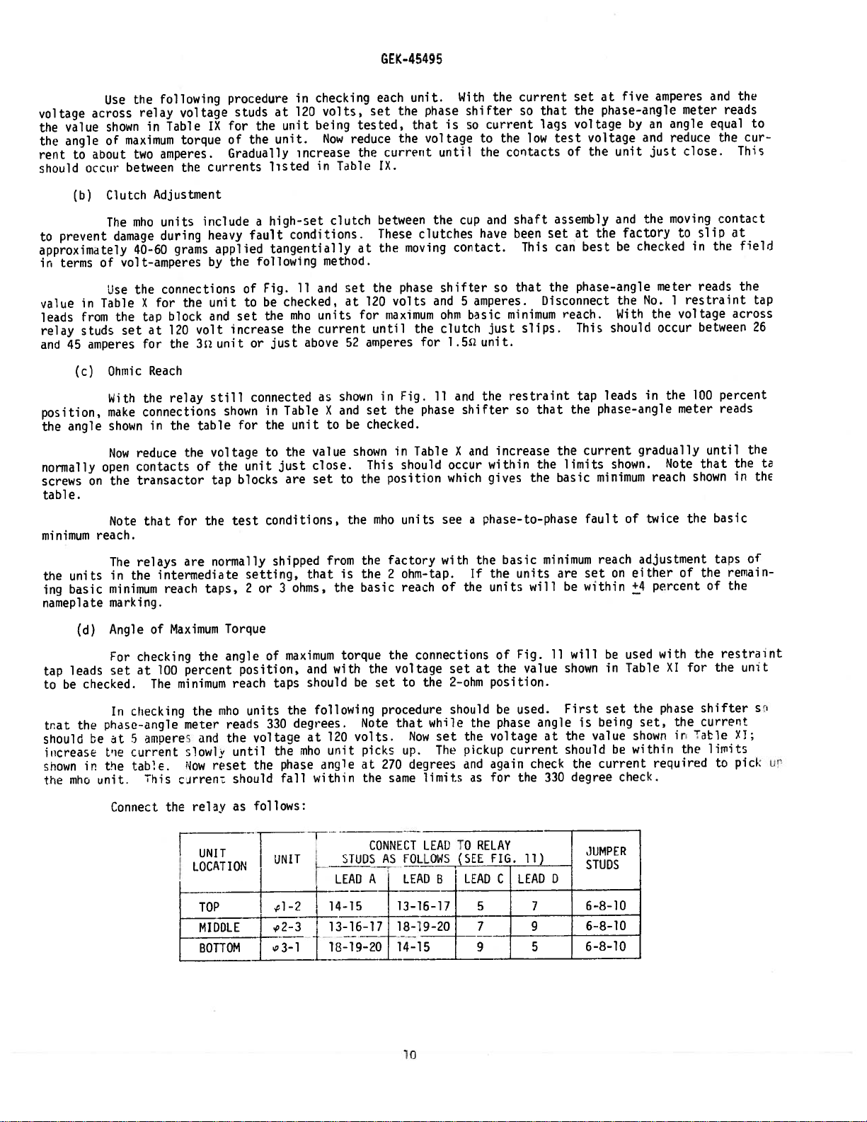
(d)
leads
checked.
the
in
mhci
Angle
For
set
In
phase-angle
he
t
‘ie
the
unit
Connect
of
checking
100
at
The
ciecking
mDeres
5
current
table.
Tii
Maximum
the
percent
minimum
the
meter
and
s1owly
:10w
carren:
relay
the
UNIT
LOCATION
TOP
MIDDLE
bTTl
Torque
angle
mho
rcset
position,
reach
reads
the
until
should
as
of
units
330
voltage
the
follows:
F-
maximum
taps
the
degrees.
nho
the
phase
fall
3T
l-2
and
with
should
following
120
at
unit
angle
within
LEAD
14-15
13-16-17
1L-19-20
torque
the
be
Note
volts.
picks
at
the
CONNECT
TUDSA
A
the
voltage
set
to
procedure
that
Now
up.
degrees
270
same
.
LEAD
13—16-17
18-19-20
l4-15
connections
set
at
position.
2—ohm
the
should
while
the
the
pickup
and
as
LEAD
voltage
again
for
set
The
limits
LEAUTORELAY
.
B
7
9
of
the
be
phase
current
C
Fig.
value
used.
check
the
11)
LEAD
7
9
5
will
11
showninTable
First
is
angle
the
at
should
the
degree
330
JUMPER
STUDS
D
6-8-10
6-8-10
6-8-10
be
set
being
value
current
used
be
check.
the
set,
shown
within
with
XI
phase
the
ir
required
the
the
for
Table
restraint
the
shifter
currert
1
imits
to
unit
Yl;
pick
sc
u
in
Page 11
TABLE
IX
tEK-45495
(CONTROL
SPRING
ADJUSTMENT)
LOCAION
TOP
MIDDLE
BOTTOM
LOCATION
TOP
MIDDLE
BOTTOM
UNIT
LO
TION
TOP
MIDDLE
BOTTOM
PHASE-ANGLE
METER
SETTING
3000
3000
300°
PHASE-ANGLE
METER
SETTING_—
300°
300°
3000
TABLE
PHASEANGLE
ANGLE
MAX.
OF
TORQUE
3000
3000
3000
TABLE
(ANGLE
XI
METER
TEST
2700
270°
2700
SOR
1.5
Volts
Volts
1.5
Volts
1.5
(OHMIC
X
O.5/l.O/1.5c1UNIT
.oc
1
—
-
READING
Volts
30
Volts
30
Volts
30
OF
MAXIMUM
ANGLES
3300
and
3300
and
and
330°
-
O,5/l.O/L5c2UNIT
ADJUSTMENT)
REACH
VA-B
SET
TAP
TORQUE
1
.5sz
5/1/1
TAP
l
30
30
30
PICKUP
]iZTAP
6.0-7.0
6.0-7.0
6.0-7.0
AT
l/2/3cUNIT
2i2
TAP
Volts
60
60
Volts
Volts
60
ADJUSTMENT)
VA-H
SET
UNIT
AT
l/2/32
2s
AMPS
—
UNIT
TAP
60
60
60
l/2/3I2UNIT
22TAP
3.0-3.5
3.0-3.5
3.0-3.5
PICKUP
AMPS
14.6-15.4
14.6-15.4
14.6-15.4
AMPS
16.5-18.5
16.5-18.5
16.5-18.5
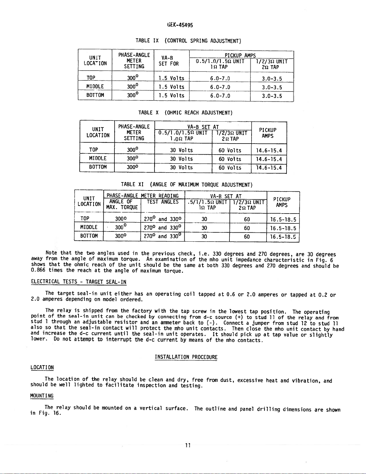
Note
away
from
shows
0.866
that
times
ELECTRICAL
target
The
2.0
amperes
The
of
1
through
so
that
increase
Do
relay
the
point
stud
also
and
lower.
LOCATION
The
The
location
be
relay
16.
should
MOUNTING
Fig.
in
that
the
the
the
TESTS
depending
seal-in
the
the
not
well
the
angle
ohmic
reach
—
seal-in
is
an
seal—in
d—c
attempt
lighted
should
two
angles
of
maximum
reach
at
TARGET
on
shipped
unit
adjustable
current
to
of
the
to
be
of
the
SEAL-IN
unit
model
from
can
contact
interrupt
relay
facilitate
mounted
used
torque.
the
angle
either
ordered.
the
be
resistor
will
until
should
on
in
unit
of
has
factory
checked
the
the
inspection
a
the
previous
An
examination
should
maximum
operating
an
with
by
connecting
and
an
protect
seal-in
current
d-c
INSTALLATION
be
clean
vertical
be
the
torque.
the
ammeter
the
ruho
unit
and
and
surface.
check,
same
coil
tap
back
unit
operates.
by
dry,
testing.
means
i.e.
the
at
330
mho
both
of
tapped
in
screw
from
d-c
source
to
(-).
contacts.
It
of
the
PROCEDURE
free
from
The
outline
degrees
unit
330
at
the
Connect
should
dust,
degrees
0.6
lowest
Then
reho
and
and
impedance
or
2.0
tap
(+)
to
jumper
a
close
pick
contacts.
excessive
panel
degrees,
270
characteristic
and
270
amperes
position.
stud
11
the
at
up
heat
drilling
degrees
or
of
from
mho
tap
and
are
and
tapped
The
the
relay
stud
12
unit
contact
value
or
vibration,
dimensions
degrees
30
in
Fig.
should
at
0.2
operating
and
stud
to
slightly
are
from
by
and
shown
6
be
or
11
hand
11
Page 12

CONNECTIONS
internal
The
external
connections
connections
shown
is
45495
GEK
typical
Fig.
10.
CEY52B
the
of
Fig.
in
relay
4.
in
shown
are
elementary
An
diagram
of
VISJL
INSPECTION
Remove
screws
all
MECHANiCAL
Recheck
To
from
TEST
eliminate
In
PORTABLE
units
mended.
impedance
fault
the
+
may
jX[
RL
is
enough
Fo
as
user
necessary
convenience
ri
relays.
the
is
This
with
arranged
distaece
well
the
ELECTRLAL
manner
The
OF
SETTINGS
To
of
have
check
purpose
which
portable
according
plugs
connections
matic
Use
is
necessary
normally
.isually
be
especially
suitable
Since
i
desirable
difference
selected
taken
being
Fig.
From
relay
the
tight.
are
INSPECTION
six
the
EQUIPMENT
the
single-phase
a
figure
this
line
the
of
switch
be
and
made
since
so
taps
a
portable
The
and
line
referred
ON
TESTS
in
section.
electrical
the
made
been
the
reactor,
test
to
the
source
of
only
considered
necessary
a
when
be
value
reactance
the
check
to
between
12
be
of
tie
it
is
should
from
adjustments
errors
RS
section
line
appear
to
it
that
field
in
test
box
source
GEI—38977.
to
MHO
THE
which
Examples
for
calibration
Cat.
14.
Fig.
in
shown
iinpedanceR
5
if
the
necessary
in
with
unit
for
used
mho
line
the
test
the
difference
seen
case
its
which
test
a-c
jX
5
+
for
impedance,
to
is
not
combination
the
testing,
box,
provided
is
impedances
UNITS
settings
reach
of
tests
particular
a
of
No.
These
Fig.
relay
at
source
the
short
this
the
of
unit
reactance,
reactor
in
twice
that
and
mentioned
may
source,
the
is
which
is
the
feasible
Cat.
calculations
this
in
mho
the
6054975;
connections
except
13
÷
be
to
is
the
connection
reach
purpose
test
pickup
tap
angle
the
check
result
source
the
tapped
relay
may
the
No.
with
may
are
line
jX5,
tested
time
setting
since
reactor
with
XL,
nearest
of
relay
that
under
from
the
relay
very
provide
to
be
fault
lO2L2Ol,
terminals
be
made
section
section.
units,
test
and
that
simulating
installation
of
may
the
and
the
reach
there
Mechanical
instrument
circuit
test
impedance,
being
is
10
percent
in
nearly
made
switch
which
readily
for
typical
for
check
to
is
it
resistor,
the
of
type
the
overreach
for
limit
to
is
to
will
this
be
fault
unit
mho
above
reactor
test
of
are
as
the
match
to
and
is
which
to
connecd.
mho
tae
suggested
test
XLA
the
current
be
tend
very
reactor
angle
twice
the
broken
no
Inspection
inaccuracies
shown
iS
SF
tested.
dnd
actual
the
portable
any
tapped
particularly
the
units
settings
ohmic
the
Cat.
and
box
test
conditions
or
during
or
checked,
to
accurately
alone,
of
the
tap
angle
or
in
in
schematic
fault
the
The
percent
1
line
test
line.
autotransformer
relay
For
a
is
are
pickup
the
that
6158546
No.
other
connections
plug
which
contact
periodic
and
limit
the
fault
it
harmonics
in
determined
due
maximum
unit
mho
impedance
of
the
cracked
section
the
to
and
form
switch,
autotransformer
so
steps
which
on
reactor
adapted
current
XL
for
and
complete
of
discussed
in
the
briefly
given
portable
arranged
be
equipment
would
coordination,
testing.
circuit
suggested
is
in
from
account
being
reach.
phase-to-neutral
the
and
reactor
test
component
on
permit
Fig.
in
and
RL
TA,
that
the
the
and
Fig.
of
testing
potential
description
section.
that
units
mho
box,
test
similar
are
now
are
encountered
be
tests
Some
a
to
that
the
its
taken
line
The
angle
unit
impedance
and
parts
ACCEPTANCE
13
jXL
which
test
13
line
is
have
the
recom
is
the
is
is
impedance
to
resistor
testing
+
the
relay
directional
circuits
the
of
CALCULATION
the
in
It
the
at
No.
Cat.
Type
with
to
included.
in
which
impedance
reasonable
reactor
a
current.
fault
calibration
the
of
reactance,
with
reach
maximum
of
is:
that
TESTS.
mho
across
be
been
test
the
is
settings
102L201;
XLA
the
practice,
are
value,
of
curve,
angular
XL,
account
used.
and
as
box
test
sche
not
will
it
reach.
unit
To
illustrete
that
has
been
by
where:
an
factory
Relay
22
example
adjusted
Z
Mm.
let
200
0=
9=
us
to
Tap
the
mho
basic
=
consider
pickup
Setting
angle
unit
minimum
at
of
angle
the
%
percent
three
12
Cos
the
of
reach
ohms
(0—0)
test
maximum
of
tap
minimum
reactor
mho
required
reach
units
impedance
on
at
and
test
the
maximum
a
autotransformer
box
torque
angle
for
of
Page 13

60
degrees.
reactor
impedance
In
impedance
is:
determining
is
8’)
deos.
2Z
the
relay
reactor
From
=
200X
the
tap
setting
above,
cos
GEK-45495
to
twice
(80-60)
use,
the
it
nay
be
relay
=
5.64
assumed
reach
ohms
that
the
at
angle
the
angle
of
the
of
(0)
test-reactor
th
te’.
Therefore,
should
degrees.
From
fore,
The
the
exact
assume
impedance
From
particular
1-
and
be
recalculated
The
the
calibration
reactance
that
of
this
reactor
0.5-ohm
table
above
the
this
calculation
taps.
use
the
b.
table
curve
of
reactance
tap
tap.
using
ow
the
may
reactor
shows
it
is
2Z
relay
for
6-ohm
is
6.1
be
calculated
-
ZL
-
it
Actually
the
sin
is
6-ohm
the
seen
the
ohms.
XL
seen
actual
=
portable
tap
86
the
tap.
angles
TAP
24
12
6
3
2
0.5
that
200X
at
the
Since
as
-
6.1
.9976
that
difference
angle
the
follows:
the
Twice
of
for
angle
cos
test
current
the
-
6
-
reactance
the
each
(86-60)
reactor
angle
115
need
the
relay
reactor
of
ANGLE
88
87
86
85
83
81
78
of
level
only
the
the
=
should
being
of
and
reach
tap
reactor
impedance
5.4
ohms
again
used.
the
impedance
the
be
taken
at
the
impedance
taps.
COS
0-60
0.883
0.891
0.899
0.906
0.921
0.934
0.951
of
be
impedance
into
angle
the
referred
For
of
account
rather
6-ohm
the
the
may
of
tap
to
purpose
6-ohm
be
assumed
on
test
than
the
in
tap
reactor
the
is
order
of
reactor
86
this
is
the
impedance
assumed
degrees.
to
illustration
86
degrees,
same
3-,
80
There
determine
for
this
2-,
the
closed
istic
angle
brated
in
degrees
30
bra
which
former
where
degree,
case
mately
The
Ficj.
is
If
of
such
‘legree
ed
‘ives
9
of
10
test
is:
13
not
the
the
test
manner
a
and
positions.
test
the
percent
is
the
30-degree
the
previous
amperes
box
autotransforrner
should
off
the
ohmic
pickup
characteristic
resistor
that
30
degrees
resistor
exact
tap
for
angle
or
to
%
be
checked
calculated
of
in
combination
when
used
respectively
The
inho
alone
as
impedance
pickup
%
Tap
of
maximum
zero-degree
tests,
flow
in
=---
the
is
the
the
(100)
to
value
mho
correct.
with
unit
the
and
at
a
torque
impedance
load
fault
tap
setting
=
determine
because
unit
with
12-
will
ohmic
line
impedance.
angle
particular
of
box
circuit
88.5%
checks
The
various
and
be
reach
for
the
value
which
required
(use
that
of
correctly
angle
reactor
6-ohm
available
at
each
angle
unit,
taken
serves
when
the
low
may,
the
The
of
0
the
to
88%
Tap)
test
current.
however,
taps
for
zero-degree
calibrated
the
is
given
is
the
from
as
source
fault
13
close
current
according
taps.
of
the
The
specified
checking
combinations
by:
angle
the
calibrated
impedance
switch
the
used
be
the
position
test
of
mho-unit
is
to
the
very
easily
calibrated
rnho
resistor
available.
the
test
should
is
closed.
high
above,
test
unit
may
resistor
contacts
enough
the
checked
test
reactor,
reach
be
checked
is
supplied
The
impedance
be
with
so
chances
by
resistor
at
test-box
data
adjusted
the
that
the
are
using
taps
impedances
the
60
by
using
with
Z
(ZL),
sheet.
to
allow
fault
character
that
the
are
at
degree
the
a
data
autotrans
is
the
As
in
switch
the
cali
pre-set
60
and
cali
sheet
60-
the
approxi
Page 14

When
becomes
the
at
apparent
checking
relatively
zero-degree
error
in
the
large
position
reach.
mho
unit
with
at
phase-angle
that
a
angles
two
GEK-4
5495
of
more
error.
or
three
This
degree
than
30
is
error
degrees
apparent
in
off
phase
from
the
Fig.
angle
maximum
12
where
will
reach
cause
position,
it
is
considerably
a
seen,
the
for
error
example,
INSPECTION
uni
ts.
cover
MHO
contact
lower
screw.
the
in
the
the
by
sary
value
reach
can
plug.
are
is
into
Before
The
armature
There
The
target
the
on
UNITS
There
should
There
jewel
If
there
bottom
jewel
All
nuts
The
felt
Determine
relay,
reduce
to
found
of
the
A
shorter
be
accomplished
All
Replace
away
from
the
placing
should
relay.
should
should
screw
of
screw.
checks
mho
units
the
station
should
just
is
the
and
gasket
the
the
the
test
should
lower
the
a
and
be
a
be
no
return
be
approximately
bearing
reason
unit
screws
on
impedance
tap
tap
with
unit
which
by
station
bus,
relay
into
contacts
screw
in
reset
promptly
noti
ceable
to
should
believe
to
and
examined.
should
the
cover
and
value
at
setting
the
calculated
low
at
currents.
will
disconnecting
have
strong
plug
and
bus
and
the
resultant
of
only
the
be
which
of
check
open
service,
the
fri
backstop
.010-015
be
screwed
that
tight,
should
phase
the
for
the
torque
the
into
target
one
when
ction
When
angle
the
relay
value.
the
phase
the
of
when
the
with
be
relay
This
most
current
to
restraint
protected
following
and
the
taps
the
reset
in
the
the
inch
firmly
jewel
replacing
particular
securely
seen
will
until
The
effect
of
the
angle
seal-in
on
button
rotating
relay
end
into
is
cracked
a
cemented
by
the
just
the
calculated
is
possible
the
circuits.
right
taps.
line
may
mechanical
units
the
is
play
place,
jewel,
attention
relays.
operate
mho
units
shown
when
All
section.
be
such
should
right-hand
at
the
structure
de-energized,
in
the
and
or
dirty
have
in
place
can
operate
value
in
Fig.
open
can
This
full
voltage
units
that
adjustments
operate
contact
bottom
of
shafts
the
top
the
the
top
paid
in
Knowing
calculated.
be
and
should
8.
circuits
be
done
should
If
the
the
units
of
the
and
of
the
pivot
screw
pivot
to
the
order
the
see
take
in
is
operate
direction
should
hand.
by
of
the
cover
mho
unit.
in
rotating
locked
assembly
in
tap
to
impedance
how
into
the
by
removing
applied.
will
the
the
keep
a-c
if
not
be
target
is
vertical
the
plugs.
It
close
account
portion
power
of
operate.
checked,
operated,
The
inho
structures.
in
place
can
shaft
Out
dust.
and
phase
is
then
the
the
and
reactive
and
position.
be
while
actual
the
of
lower
seal-in
with
unit
by
its
removed
screwing
angle
only
shorter
the
connection
reactive
power
the
moving
The
set
from
seen
neces
tap
relay
flow
flow
In
periodic
depending
as
accumulated
is
suggested
yea
rs.
CONTACT
For
ble
strip
acton
Its
flexibility
oaper
or
view
of
test
upon
that
CLEANING
cleaning
of
metal
is
so
delicate
cloth
the
vital
program
environment,
enough
the
fine
with
insures
of
any
role
be
followed.
type
experience
points
listed
silver
an
etched—roughened
that
no
the
cleaning
kind
to
PERIODIC
of
protective
of
to
contacts,
scratches
clean
It
relay
select
under
of
relay
CHECKS
relays
recognized
is
and
the
the
test
INSTALLATION
a
flexible
surface
are
left,
the
actual
contacts.
AND
ROUTINE
in
that
users
interval
burnishing
resembling
yet
it
points
14
MAINTENANCE
the
operation
the
interval
experience
best
PROCEDURE
tool
in
will
clean
of
contact.
be
effect
with
suited
checked
should
off
ofapower
between
periodic
his
to
at
be
used.
a
superfine
any
corrosion
Do
not
system
periodic
an
use
it
testing.
individual
interval
This
file.
thoroughly
knives,
is
checks
until
requirements
of
consists
The
files,
important
will
the
from
of
polishing
and
abrasive
vary
one
a
rapidly.
that
user
to
flexi
a
it
two
Page 15

If
liniits,
calibrations
as
factory
Fig.
1
and
R
21
R
12
R
22
R
13
R
23
it
is
they
should
be
adjustments,
2.
-
l-2
-
-
2-3
-
—
3-l
-
found
made
Their
unit
unit
unit
unit
unit
unit
during
be
recalibrated
in
are
locations
r’hmic
angle
ohmic
angle
ohmic
angle
the
of
reach
of
reach
of
the
installation
laboratory.
used
in
reach
maximum
maximum
maximum
as
outlined
in
recalibrating
the
relay
adjustment
torque
adjustment
torque
adjustment
torque
or
The
circuit
GEK-4
SERVICING
periodic
in
circuit
the
adjustment
adjustment
adjustment
5495
tests
the
following
components
units.
are
shown
that
paragraphs.
listed
These
in
the
the
parts
internal
niho
below,
may
unit
It
which
be
connection
calibrations
is
suggested
are
physically
are
normally
located
diagrams
out
that
considered
of
of
these
from
Fig.
10.
a.
basic
5
amperes
shown
the
spring
tacts
If
they
b.
from
and
5
amperes,
in
the
adjust
c.
from
sure
aniperes,
angle
as
described
330
degrees
test
The
pickup
cent.
330
degrees.
Control
Make
Make
Now
unit
Ohmic
The
the
be
Angle
The
the
that
The
by
First,
volts
NOTE:
reach
in
Table
reduce
being
adjusting
were
were
basic
front
sure
table
the
angle
front
the
procedure
at
30
and
should
Refine
Before
to
heat
taps
position
Spring
connections
taps
should
sure
that
and
the
XII.
the
adjusted.
ring
closing
closing
Reach
Adjustment
minimum
of
that
the
and
voltage
for
the
appropriate
of
Maximum
of
maximum
of
the
basic
a
specified
degrees.
the
reach
in
paragraph
(Note
that
adjust
then
the
adjustments
making
up
lead
so
Adjustment
the
voltage
voltage
below
above
the
relay.
basic
unit
Torque
relay.
minimum
used
The
of
phase-angle
the
be
for
set
that
to
the
be
relay
(see
the
reach
at
120
to
rheostat
torque
in
setting
set
test
the
(b)
proper
checked
pickup
or
approximately
for
100
the
units
relay
set
in
is
in
at
VA_B
to
the
Insert
Fig.
the
set
of
the
15)
point
set
the
Connect
minimum
volts
be
checked.
so
of
Use
the
reach
taps
voltage
angles,
unit
at
and
Table
adjustments
reactor
at
of
rheostats
phase-angle
percent.
as
shown
the
position
an
120
volts,
test
blade
and
point,
mho
the
reach
set
that
the
connections
are
angle
VAB,
set
its
270
15
are
upright
voltage
turn
shown
the
units
relay
taps
the
Now
the
mho
of
will
voltages,
angle
XIV.
so
degrees
until
minutes
Also
level.
in
set
of
a
the
in
adjusting
can
are
phase
reduce
unit
units
in
the
maximum
be
of
Next
should
that
adjustments
energized
it
is
Fig.
11
for
the
position
phase
value
thin
screwdriver
ring
Table
be
adjusted
as
shown
in
the
shifter
the
picks
can
be
in
Fig.
position
torque
the
same
and
maximum
set
be
the
ohm
with
the
the
pickup
important
and
basic
so
shifter
and
until
XII,
ring
in
position
so
voltage
up
at
adjusted
11.
at
the
torque
the
phase
made
unit
same
on
set
that
set
the
the
should
Fig.
that
15
shown
is
to
angles
pickup
at
closes
is
the
with
that
the
niinimuni
the
so
that
the
current
into
contacts
adjusting
by
means
11;
shown
the
VAB
amperes
by
Leave
in
Table
adjust
leading
amperes
should
shifter
120
set
voltage
within
mho
Units,
rated
the
restraint
reach
units
the
one
of
ring
be
turned
of
leave
in
phase-angle
to
the
+5
means
the
restraint
the
be
so
volts
its
contacts
limits
voltage
relay
tap
shown
are
level.
phase-angle
at
the
of
the
the
should
to
the
rheostats
the
Table
set
percent.
of
rheostats
XIV.
reactor
and
are
checked
that
and
5
and
should
at
both
the
units
alone
be
leads
in
value
slots
unit
the
restraint
XIII.
meter
value
taps
so
lagging
shown
and
the
amperes).
at
should
and
mounted
on
Table
XII.
With
meter
shown
in
the
just
close.
be
turned
left.
which
taps
With
reads
shown
which
to
100
that
the
in
Table
adjusted
phase-angle
17.3
amperes
be
17.3
270
degrees
be
the
restraint
in
an
100
percent.
the
current
reads
in
Table
edge
to
are
at
current
the
in
Table
are
percent
the
pickup
maximum
XIV.
if
meter
Then
set
amperes
and
allowed
upright
the
of
If
the
the
right.
accessible
100
percent
at
angle
XIII
accessible
torque
necessary
reads
VAB
+5
percent.
+5
set
value
XII
the
shown
and
at
per
The
at
for
con
and
be
15
Page 16

Note
unit,
whenever
reach
and
and
that
vice-versa.
its
angle
angle
an
adjustment
of
Therefore,
of
maximum
maximum
of
torque
torque
the
to
until
ange
insure
settinc
both
of
accurate
maximum
is
changed,
are
within
GLK-45495
torque
settings,
and
the
will
to
limits
have
it
is
continue
specified
a
secondary
necessary
a
cross
above.
to
effect
recheck
adjustment
on
the
the
reach
reach
routine
of
the
of
unit
a
of
Connect
the
relay
as
LOCATION
TOP
MIDDLE
BOTTOM
LOiiuN
MIDDLE
r
UNIT
LOCATION
follows:
TOP
BOTTOM
PHASE-ANGLE
UNIT
;l-2
L
2-3
‘3-l
PHASE-ANGLE
METER
SETTING
3000
3000
3000
METER
SETTING
CONNECT
STUDS
AS_FOLLOWS
L[AD
A
14-15
13-16-17
18-19-20
1.5
1.5
—
L5Volts
0.5/1.0/l.5i2UNIT
13-16—17
18-19-20
14-15
TABLE
JL1
Volts
Volts
TABLE
VA-B
l.O2TAP
LEAD
TO
RELAY
(SEE
LEADBLEAD
5
7
9
XII
PICKUP
O.5/l.O/l.5c2UNIT
TAP
l
Amp
6.5
6.5
Amp
Amp
6.5
XIII
AT
SET
l/2/3c2UNIT
2c2TAP
FIG.
C
11)
LEAD
AMPS
D
7
9
5
(±10%)
l/2/3c2UNIT
3.25
3.25
3.25
PICKUP
AMPS
4-5%
2c2
JUMPER
6-8-10
6-8-10
6-8-10
TAP
Amp
Amp
Amp
—______
ADJUST
adiusted
slightly.
the
phase-angle
the
proper
current
is
made
As
With
Lz
noted
upto75
To
restraint
rheostat
at
both
make
sure
TOP
MIDDLE
BOTTOM
UNIT
LOCATION
TOP
MIDDLE
in
Table
degrees
make
this
tap
meter
so
test
angles
the
PHASE-ANGLE
ANGLE
300°
300°
300°
under
if
315
the
should
OF
TORQUE
desired.
lock
MAX.
II
adjustment
settings
reads
that
rheostat
3000
300°
300°
METER
the
section
refer
at
100
degrees,
unit
be
nuts
TEST
270°
270°
270°
just
within
READING
and
and
and
If
this
to
percent
set
picks
are
30
30
30
ANGLES
33Q0
330°
330°
on
RATINGS,
change
Table
and
to
VAB
up.
±5
percent
tight.
Volts
Volts
Vol
ts
TABLE
.5/lf1.5c2
XV
and
connections
test
Now
XIV
is
TAP
lc
30
30
30
the
made,
proceed
volts
check
of
the
60
60
60
VA-B
UNIT
angle
Volts
Volts
Vol
SET
the
as
per
and
the
value
ts
AT
h/2/3c!UNIT
2
60
60
60
of
maximum
reach
outlined
Fig.
the
current
pickup
listed
15
15
15
TAP
of
11,
current
torque
the
below.
set
in
PICKUP
niho
the
to
the
Rh
R12
Rl
3
AMPS
+5%
17.3
17.3
17.3
of
units
12.5
at
table.
F
the
phase
amperes.
255
ADJUST
R21
R22
R23
mho
will
shifter
degrees.
After
units
increase
so
Now
The
the
can
that
adjust
pickup
setting
be
16
Page 17

d.
wrrnch
rotates
in
either
set
Core
This
(catalog
the
position.
LOCATION
Adjustment
adjustment
no.
core
direction
UNIT
TOP
MIDDLE
BOTTOM
(See
is
0178A9455
“A’
to
although
0
AT
TORQUE
285°
285°
285°
Fig.
to
be
obtain
ANGLE
MAX
17)
made
Pt.
the
it
should
METER
READS
TEST
ANGLES
3150
255°
1
j
255°
315°
25I15°
only
if
1)
the
values
not
relay
core
shown
be
GEK-4
TABLE
O.5/l.0/1.5c2
ls
30
30
30
does
is
adjusted
under
necessary
5495
XV
VA_B_SET
TAP
Volts
Volts
Volts
not
meet
by
Directional
to
UNIT
inserting
rotate
l/2/3&2
2m
60
60
60
Directional
Tests.
the
TAP
Volts
Volts
Volts
the
core
UNIT
Tests.
wrench
The
more
PICKUP
AMPS
+5f
14.4
14.4
14.4
core
than
By
to
may
ADJUST
R21
R22
R23
means
engage
be
a
few
of
nut
rotated
degrees
a
“0”
special
which
360
from
degrees
its
It
rep’acement
When
quantity
relay
was
ii
reconinended
of
ordering
required,
furnished.
any
that
renewal
name
that
are
of
sufficient
worn,
parts,
the
part
broken,
address
wanted,
quantities
or
the
and
RENEWAL
of
damaged.
nearest
give
PARTS
renewal
Sales
the
General
parts
Office
be
of
Electric
carried
the
in
General
Requisition
stock
Electric
to
enable
number
the
Company,
on
which
prompt
specify
the
17
Page 18

TARGET
SEAL-IN
UNIT
Ru
R21
GEK-45
495
I
UPPER
TAP
RESTRAINT
MHO
UNIT
c
-2
BLOCK
TAPS
MHO
c
RT3
R23
2-3
UNIT
—
BLOCK
LOWER
RESTRAINT
MHO
TAP
TAPS
UNIT
3-1
PIG.
(8036590)
I
MHO
DISTANCE
RELAY
18
REMOVED
FROM
CASE,
FRONT
VIEW
Page 19

c1
1-2
TAP
BASIC
BLOCK
MIN.
REACH
‘
K
E
-45495
“I
2-3
f
TAP
BASIC
TAP
BASiC
BLOCK—
MIN.
BLOCK
MIN.
REACH
REACH
FIG.
2
8O428O7)
MHO
DISTANCE
RELAY
19
REMOVED
FROM
CASE,
REAR
VIEW
Page 20

OF
ANGLE
LA.G)
AT
1ST-IC
(600
ACCURACY
UNIT
U
m
U,
MHO
CHARACtER
TOR2UE
DYNAMIC
CHARACTERISTIC
AND
CEY52B
TYPE
STATIC
DYNAMIC
STATIC
‘,AAXIMUM
OF
ZMNIMUM
*
I3
I
a
-I
m
a
a
a
m
C,
m
-1,
a
-1
a
-I
r’J
rn
-C
F’,)
C-)
r’l
r’l
Page 21

GEK-45495
.
.1
I
II
I
V
‘Fl
LINE
J
f3c1
FIS1
(1ANI
-
03
---—5----
T
vOj
I(
TI’
PI’IN’-V
L
15-
I
yr
—
-
0
I
A
.--
0’-
I
__
-.
1
I——I’-—•
‘“t
-
L1
1’5-
IP_9_ø2.
---;-
‘--—‘
:
--
-,
-5,-S
U
r:r
‘IT
U
S
REST
03
—cli-
--i
02-3
03-I
02-3
r
FIG.
NOTE
W1.N
7
RP
“0
4
(0108B8961-O
IJ$INc-AIJVILIARY
TWO
AlIAS.
SAP
‘ONNECT’A
0.C”.
IJE
TRIP
SH.
RELAY
4LrE4AIE
1
TO
ç94
CONNECTION
&
2)
TYPICAL
EXTERNAL
CONNECTIONS
21
TU
DEVICE
CEYS2B
21
rLcEV28’rNI,
1Z’.
DEVICE
CEYS2I3
CEX
54441713
L
2013
FOR
F
THE
541.4176
0269A3027
024
020A
102L2I8
PC
7’.
INTERNAL
6A6R30
24
Gil
AUERNACE
I3
2i
P
CEY52B
DESCRIPTION
IMHO
.ELOND
31
DIS1’*34CE.R[Iil
ZCINE
TIMER
OUTLINE
017647336
0x6A3824
4
6209274
OIO4ABS23
RELAY
J
Page 22

0-
GEK-45495
B/CK
E
P
CL
(E,2)
FRONT
FL
/I
0/
rDI
TING
I
TM[•
TAP
RESTFAINT
SETTING
Hi.
)8A55,’/—))
SCHEMATIC
COM4ECTIONS
2
IYPICALM2UNIT
OF
Page 23

GEK-45495
1.25
—
—
-
—
/
1.0
r
J
/
_“%
/
/
I
I.LJI
‘5ETT
flUC
I
I
NO
\
600
1.0
SETTING
OHM
/
‘I
/
/
/
.75
/
/
/
\
\
I
/
/
/
50
/
/
\
.25
/
Y
I
I,
1
I,
/
/
/
FIG.
6
(0178A8174-O)
.25
IMPEDANCE
CHARACTERISTIC
.50
OF
/
/
MHO
/
/
UNIT
1’
.75
R
OHMS
Page 24

r
L_
GEK-
45495
—
—
—
FIC.
—
—
7
(0208A3751-P
FETPANT
PE
RAINT
TAP
TAP
TAP
BLOCK
ARRANGEMENT
ETTINC
PETT
NC
AND
EIE.2
SETTINGS
24
Page 25

AND
UNI
LAG)
MAXIMUM
MO
(60°
TIME
5213
ANGLE
CEY
\OLTS
120
FAULT=
SETTING
TAP
BEFORE
VOLTAGE
RESTRAINT
01
01
200
MINIMUM
Z
*
30
1
TN’FE
IO0°/
OPERATIN(
TQRoUE
RELAY
S
4-fl
NJ
-n
P
4
a
L)
-J
(J)
1_U
z
>-
L)
—1
m
LU
F
rl
01015°
2
CL
0
z
LU
—4
cz
-1
LU
c
LU
4:
01
0
4:
>
5°
I
t’.
Page 26

GEK—45495
CONNECTING
NOTE
AFTER
TRAVELS
THE
TERMINAL
AUXILIARY
ENGAGING
INCH
¼
PLUG
BEFORE
BLOCK
MAIN
BRUSH
AUXILIARY
ENGAGING
BRUSH
I
CONNECTING
TERMINAL
SHORTING
BLOcK\
BAR
BRUSH,CONNECTING
THE
MA1N
BRUSH
BLOCK
PLUG
ON
CROSS
SECTIONOFDRAWOUT
CASE
SHOWING
26
POSITION
AUXILIARY
OF
BRUSH
AND
SHORTING
BAR
Page 27

7c
U,
a
-
---
A-
__-j
--
-o
0
Hft
‘—I
-.-
*
II
C
—
.--
—-
C>---—
H
cc-c
zz
z
*
cOC>
@
rn
cr
*
0
z
ri
Jo
cJl
NJ
a
a
a
I
—1
a
a
a
r’)
0,
P1
a
a
P1
N3
a
(1,
a
a
Jo
a
Page 28

GEK—45495
VARIAC
A
B
C
PHASE
THE
30,
ANGLE
VOLTAGE.
LOV
METER
READS
THE
ANGLE
THAT
THE
14
CURRENT
D
LEADS
9
O1-’A.1’1—l)
I
TES
NN[CITONS
OR
28
CHECKING
THE
CORRECT
MHO
UNIT
C
TION
Page 29

GEK-4
5495
x
TWICE
REACH
UNIT
AT
TEST
IN
2
M
TAP
R
3.
12
(U195A992-O)
DIAGRAM
SHOWING
REACH
29
OF
MHO
UNIT
AT
ANGLE
OF
TEST
REACTOR
Page 30

VOLTS
115
SYSTEM
FREQ.
CEK-
RS
(LOAD
45
495
BOX)
-4-
LEAD
LEAD
A
B
UNIT
LOCATION
TOf’
MIDDLE
8OTTOIJ
—
LEAD
JNIT
01-2
2-3
0
Wji
D
CONNECT
A
LEAD
14—15
13—16—17
18—19—20
FG.
3
LEAD
LLEAD
13—16—17
18—19—20
14—15
54Y1i_)
O
TO
LEAD
RELAY
B
M-(
C
STUDS
IjIEAD
JIT
AS
5
7
TLT
FOLL(YWS
C
CONNLCIrONS
LEAD
5
—
JUMPER
RELAY
D
STUDS
6—C
—
6—.-1O
1
Page 31

®3I
dO!
®
96t79t7-N3J
GNV
SA’1I
()
SNOJID]NNOD
0
® ®
®
IS]!
X1ld
GD
(
103C0
3SVHd
d]13r
VNd
GNV
01
I
3DV110A
]19NV
]SVHd
01
D3HD
.LN3ddflD
3—T
MOld
—
V
10-
ISVHd
]1ONV
d]13Y
0!
Il-U
V
HuM
ISVl-ld
O1flOHS
1110
IAO8V
3VHd
d]VJd8
0V3d
]DdflOS
8
31JNV
31NV
OdJZ
NOIIVIS
118
GD
SNOIIDINNOD
di13r
d313b
3iS3G
3I
!31
®
dO!
CU08
S1
ISIC’I!O8
fl1d
1SI
LT1
+:‘J
®
1I1d
GD
1
‘Dfl1d
!
0I
(9rnd
L
61
03
]19NV
]VHd
GN
TIONV
3Viki
SVHd
(q)
SNOIID]NNOD
d]!]N
E
]V
I—
SN0i1DNNOD
d]Hr
3
—3
01
01
1N&flD
01
01
lNlddflD
3DV11OA
SVHd
)D]HD
V110A
SVHd
D]HD
GNV
03
L08
c
1s31
j;
t
(‘
Oflid
t6ot7Vi6tC)
11èi
IS].
SNOI.LJiNNOD
TE
iO
1J
Ni)iD3HD
1\iNè3.LX3
ONIIt.
UL
AV13’d
Page 32

GEK-45495
SPRING
ADJUSTING
RING
STATIONARY
CONTACT—
I
UPPER
AS
SE
PIVOT
MBLY
CONTROL
SPRING
A
-4
‘BACKSTQp
‘I
MOV
I
N
CONTACT
G
FIG.
(8034958)
15
FOUR
POLE
INDUCTION
CYLINDER
32
UNIT, TYPIFING
CONSTRUCTION
IN
T9E
CEY5213
RELAY
Page 33

GEK-454q5
M”_
+
OUTLINE
)
I’.
\[
-F5H-----
10-3?
M1C,
RE
SC
IJiAT
X
WS(6)
ION
SURFACE
MTG—r-
L9MM.
-J
PA
N
.75
EL
(OPTIO’AL
IC
—2.
(RE\
IThD
CUTOUT
MAY
REPLACE
DRILLED
HOL5
NUMEF-UNL,
(EAK
1715
—I9
00000
00000
2018
7
00000
\0000c
10
6
33
S.25__
__E
L____.
6
S
Ic
6
11k
ur
14
531
4
Ew)
13
51
12
2
JDS
II
__
37M)
•9?75
6
(CI-
1.71
LI
:)
PtJ:L
‘i’.
I
CUT
1
OJT
.—
DRILLING
JNTINC,
*
F.
*
indicates
-t
(FRONT
16
(0178A7336-4)
Revision
FOR
SELU-FLUSH
yEw)
OUTLINE
VIEW
SHOWING
AEBLY
H-\RDWARF.
SU1FACE
ON
rEEL
S
AND
PANEL
Is
STUD
OF
FOR
MTG
PANELS
DRILLING
33
PANEL
FACE
DIMENSIONS
MO.I
EOR
ULL1NG
HJC(PNT
ThE
CEYb?B
FQ.
RELO’
(502MM)
19.75
JR
V1EV/1
Page 34

I,,
:D
Dc.
C
j)
—
-I
cm
>
>
C)
m
0
c-i)
C)
—--
r
):‘.
>
—i
c
<C-
C)>
U,
-9
—-I
cc
Lfl
C
Page 35

Page 36

GE
Power
Management
Anderson
215
Markham,
Canada
Tel:
Fax:
www.ge.comlindsyslpm
L6E
(905)
(905)
Avenue
Ontario
1B3
294-6222
201-2098
 Loading...