

Page 1

GE Healthcare
(NOVEMBER 4, 2013)
VE6_VE8_COVER.FM
PRELIMINARY
0123
Voluson E-Series BT15 - BT20
Proprietary Service Manual
English (English)
Voluson E6 / Voluson E8 / Voluson E10 with Software version EC300, 15.x.x (BT15)
•
Voluson E6 / Voluson E8 / Voluson E10 with Software version EC310, 16.x.x (BT16)
•
Voluson E6 / Voluson E8 / Voluson E10 with Software version EC320, 17.x.x (BT17)
•
Voluson E6 / Voluson E8 / Voluson E10 with Software version EC330, 18.x.x (BT18)
•
Voluson E6 / Voluson E8 / Voluson E10 with Software version EC340, 19.x.x (BT19)
•
Voluson E6 / Voluson E8 / Voluson E10 with Software version EC350, 20.x.x (BT20)
•
ADVANCED SERVICE DOCUMENTATION
COPYRIGHT GENERAL ELECTRIC COMPANY
GE CONFIDENTIAL
UNLICENSED USE BY NON-GE PARTIES IS STRICTLY PROHIBITED
Document Number: 5539549APB
Revision 8
© 2014 - 2019 by General Electric
Page 2

Revision History
Revision Date Reason for change
1 May 2014 Preliminary Release (MV)
2 August 2014 Initial Release (M3)
3 May 2015 General Update and Improvement, new parts
4 August 2015 Implementation of EC310 (BT16)
5 July 2016 Implementation of EC320 (BT17), general update
6 August 2017 Implementation of EC330 (BT18), general update
7 August 2018 Implementation of EC340 (BT19), general update
8 August 2019 Implementation of EC350 (BT20), general update
i-ii
Voluson E-Series Proprietary Service Manual
5539549APB Revision 8
Page 3

Chapter 1 – Introduction
1.1 Important Precautions - - - - - - - - - - - - - - - - - - - - - - - - - - - - - - - - - - - - - - - - - - - - 1-2
1.2 Legal Notes - - - - - - - - - - - - - - - - - - - - - - - - - - - - - - - - - - - - - - - - - - - - - - - - - - - 1-11
1.3 Purpose of this Service Manual - - - - - - - - - - - - - - - - - - - - - - - - - - - - - - - - - - - - - 1-12
1.3.1 Typical Users of the Proprietary Service Manual - - - - - - - - - - - - - - - - - - - - - - - - - - 1-12
1.3.2 Models covered by this Manual - - - - - - - - - - - - - - - - - - - - - - - - - - - - - - - - - - - - - - 1-13
1.3.3 System History - Hardware and Software Versions - - - - - - - - - - - - - - - - - - - - - - - - 1-14
1.3.3.1 How to identify the Systems - - - - - - - - - - - - - - - - - - - - - - - - - - - - - - - - - - - - 1-15
1.3.4 Purpose of Operator Manual(s) - - - - - - - - - - - - - - - - - - - - - - - - - - - - - - - - - - - - - - 1-15
1.4 Important Conventions - - - - - - - - - - - - - - - - - - - - - - - - - - - - - - - - - - - - - - - - - - - 1-16
1.4.1 Conventions used in this Manual - - - - - - - - - - - - - - - - - - - - - - - - - - - - - - - - - - - - - 1-16
1.4.2 Standard Hazard Icons - - - - - - - - - - - - - - - - - - - - - - - - - - - - - - - - - - - - - - - - - - - - 1-16
1.4.3 Product Labels and Icons - - - - - - - - - - - - - - - - - - - - - - - - - - - - - - - - - - - - - - - - - - 1-18
1.5 Safety Considerations - - - - - - - - - - - - - - - - - - - - - - - - - - - - - - - - - - - - - - - - - - - 1-20
1.5.1 Introduction - - - - - - - - - - - - - - - - - - - - - - - - - - - - - - - - - - - - - - - - - - - - - - - - - - - - 1-21
1.5.2 Human Safety - - - - - - - - - - - - - - - - - - - - - - - - - - - - - - - - - - - - - - - - - - - - - - - - - - 1-21
1.5.3 Mechanical Safety - - - - - - - - - - - - - - - - - - - - - - - - - - - - - - - - - - - - - - - - - - - - - - - 1-22
1.5.4 Electrical Safety - - - - - - - - - - - - - - - - - - - - - - - - - - - - - - - - - - - - - - - - - - - - - - - - - 1-23
1.5.4.1 Safe Practices - - - - - - - - - - - - - - - - - - - - - - - - - - - - - - - - - - - - - - - - - - - - - - 1-23
1.5.4.2 Probes - - - - - - - - - - - - - - - - - - - - - - - - - - - - - - - - - - - - - - - - - - - - - - - - - - - 1-23
1.5.5 Auxiliary Devices Safety - - - - - - - - - - - - - - - - - - - - - - - - - - - - - - - - - - - - - - - - - - - 1-23
1.5.6 Labels Locations - - - - - - - - - - - - - - - - - - - - - - - - - - - - - - - - - - - - - - - - - - - - - - - - 1-25
1.5.6.1 Identification and Rating Plate - - - - - - - - - - - - - - - - - - - - - - - - - - - - - - - - - - - 1-25
1.5.7 Dangerous Procedure Warnings - - - - - - - - - - - - - - - - - - - - - - - - - - - - - - - - - - - - - 1-25
1.5.8 Lockout/Tagout (LOTO) Requirements - - - - - - - - - - - - - - - - - - - - - - - - - - - - - - - - 1-26
1.5.9 Returning/Shipping System, Probes and Repair Parts - - - - - - - - - - - - - - - - - - - - - - 1-26
1.6 EMC, EMI and ESD - - - - - - - - - - - - - - - - - - - - - - - - - - - - - - - - - - - - - - - - - - - - - 1-27
1.6.1 What is EMC? - - - - - - - - - - - - - - - - - - - - - - - - - - - - - - - - - - - - - - - - - - - - - - - - - - 1-27
1.6.2 Compliance - - - - - - - - - - - - - - - - - - - - - - - - - - - - - - - - - - - - - - - - - - - - - - - - - - - - 1-27
1.6.3 Electrostatic Discharge (ESD) Prevention - - - - - - - - - - - - - - - - - - - - - - - - - - - - - - 1-27
1.7 Customer Assistance - - - - - - - - - - - - - - - - - - - - - - - - - - - - - - - - - - - - - - - - - - - - 1-28
1.7.1 Contact Information - - - - - - - - - - - - - - - - - - - - - - - - - - - - - - - - - - - - - - - - - - - - - - 1-28
1.7.2 System Manufacturer - - - - - - - - - - - - - - - - - - - - - - - - - - - - - - - - - - - - - - - - - - - - - 1-29
Table of Contents
Chapter 2 – Site Preparation
2.1 General Requirements - - - - - - - - - - - - - - - - - - - - - - - - - - - - - - - - - - - - - - - - - - - - 2-2
2.1.1 Environmental requirements - - - - - - - - - - - - - - - - - - - - - - - - - - - - - - - - - - - - - - - - - 2-2
2.1.1.1 Cooling - - - - - - - - - - - - - - - - - - - - - - - - - - - - - - - - - - - - - - - - - - - - - - - - - - - - 2-2
2.1.1.2 Lighting - - - - - - - - - - - - - - - - - - - - - - - - - - - - - - - - - - - - - - - - - - - - - - - - - - - 2-2
2.1.2 Electrical Requirements - - - - - - - - - - - - - - - - - - - - - - - - - - - - - - - - - - - - - - - - - - - - 2-2
2.1.2.1 Voluson Power Requirements Voluson E-Series - - - - - - - - - - - - - - - - - - - - - - 2-2
2.1.2.2 Inrush Current - - - - - - - - - - - - - - - - - - - - - - - - - - - - - - - - - - - - - - - - - - - - - - - 2-3
2.1.2.3 Site Circuit Breaker - - - - - - - - - - - - - - - - - - - - - - - - - - - - - - - - - - - - - - - - - - - 2-3
2.1.2.4 Site Power Outlets - - - - - - - - - - - - - - - - - - - - - - - - - - - - - - - - - - - - - - - - - - - - 2-3
2.1.2.5 System Power Plug - - - - - - - - - - - - - - - - - - - - - - - - - - - - - - - - - - - - - - - - - - - 2-3
2.1.3 EMI Limitations - - - - - - - - - - - - - - - - - - - - - - - - - - - - - - - - - - - - - - - - - - - - - - - - - - 2-3
2.1.4 Environmental Requirements for Probes - - - - - - - - - - - - - - - - - - - - - - - - - - - - - - - - 2-4
2.1.5 Time and Manpower Requirements - - - - - - - - - - - - - - - - - - - - - - - - - - - - - - - - - - - - 2-4
2.1.6 System Specifications - - - - - - - - - - - - - - - - - - - - - - - - - - - - - - - - - - - - - - - - - - - - - 2-5
2.1.6.1 Physical Dimensions of Voluson E-Series - - - - - - - - - - - - - - - - - - - - - - - - - - - 2-5
2.1.6.2 Acoustic Noise Output - - - - - - - - - - - - - - - - - - - - - - - - - - - - - - - - - - - - - - - - - 2-5
2.1.6.3 Electrical Specifications - - - - - - - - - - - - - - - - - - - - - - - - - - - - - - - - - - - - - - - - 2-5
2.2 Facility Needs - - - - - - - - - - - - - - - - - - - - - - - - - - - - - - - - - - - - - - - - - - - - - - - - - - 2-6
2.2.1 Purchaser Responsibilities - - - - - - - - - - - - - - - - - - - - - - - - - - - - - - - - - - - - - - - - - - 2-6
2.2.2 Required Facility Needs - - - - - - - - - - - - - - - - - - - - - - - - - - - - - - - - - - - - - - - - - - - - 2-7
2.2.3 Desirable Features - - - - - - - - - - - - - - - - - - - - - - - - - - - - - - - - - - - - - - - - - - - - - - - 2-8
2.2.4 Network Setup Requirements - - - - - - - - - - - - - - - - - - - - - - - - - - - - - - - - - - - - - - - - 2-8
Voluson E-Series Proprietary Service Manual
5539549APB Revision 8
i-iii
Page 4

Table of Contents
2.2.4.1 Stand-alone System (without Network Connection) - - - - - - - - - - - - - - - - - - - - - 2-8
2.2.4.2 System connected to Hospital's Network - - - - - - - - - - - - - - - - - - - - - - - - - - - - 2-8
2.2.4.3 Purpose of the DICOM Network Function - - - - - - - - - - - - - - - - - - - - - - - - - - - 2-8
2.2.4.4 DICOM Option Pre-Installation Requirements - - - - - - - - - - - - - - - - - - - - - - - - 2-8
Chapter 3 – Setup Instructions
3.1 Setup Reminders - - - - - - - - - - - - - - - - - - - - - - - - - - - - - - - - - - - - - - - - - - - - - - - - 3-2
3.1.1 Average Installation Time - - - - - - - - - - - - - - - - - - - - - - - - - - - - - - - - - - - - - - - - - - - 3-2
3.1.2 Installation Warnings - - - - - - - - - - - - - - - - - - - - - - - - - - - - - - - - - - - - - - - - - - - - - - 3-2
3.1.2.1 Moving/Lifting the System - - - - - - - - - - - - - - - - - - - - - - - - - - - - - - - - - - - - - - 3-2
3.1.2.2 System Acclimation Time - - - - - - - - - - - - - - - - - - - - - - - - - - - - - - - - - - - - - - - 3-3
3.1.2.3 Control Console Positioning - - - - - - - - - - - - - - - - - - - - - - - - - - - - - - - - - - - - - 3-3
3.1.2.4 Brake Pedal Operation - - - - - - - - - - - - - - - - - - - - - - - - - - - - - - - - - - - - - - - - - 3-3
3.1.3 Safety Reminders - - - - - - - - - - - - - - - - - - - - - - - - - - - - - - - - - - - - - - - - - - - - - - - - 3-4
3.2 Receiving and Unpacking the System - - - - - - - - - - - - - - - - - - - - - - - - - - - - - - - - - 3-5
3.3 Preparing for Setup - - - - - - - - - - - - - - - - - - - - - - - - - - - - - - - - - - - - - - - - - - - - - - 3-7
3.3.1 Verify Customer Order - - - - - - - - - - - - - - - - - - - - - - - - - - - - - - - - - - - - - - - - - - - - - 3-7
3.3.2 EMI Protection - - - - - - - - - - - - - - - - - - - - - - - - - - - - - - - - - - - - - - - - - - - - - - - - - - 3-8
3.4 Completing the Setup - - - - - - - - - - - - - - - - - - - - - - - - - - - - - - - - - - - - - - - - - - - - - 3-9
3.4.1 Power On / Boot Up - - - - - - - - - - - - - - - - - - - - - - - - - - - - - - - - - - - - - - - - - - - - - - - 3-9
3.4.1.1 During a normal boot, you may observe - - - - - - - - - - - - - - - - - - - - - - - - - - - - 3-11
3.4.2 Power Off / Shutdown - - - - - - - - - - - - - - - - - - - - - - - - - - - - - - - - - - - - - - - - - - - - 3-12
3.4.3 Probe Connection - - - - - - - - - - - - - - - - - - - - - - - - - - - - - - - - - - - - - - - - - - - - - - - 3-13
3.5 Connection of Auxiliary Devices - - - - - - - - - - - - - - - - - - - - - - - - - - - - - - - - - - - - 3-14
3.5.1 Connecting the LCD Monitor - - - - - - - - - - - - - - - - - - - - - - - - - - - - - - - - - - - - - - - - 3-15
3.5.2 Connecting the OLED Monitor - - - - - - - - - - - - - - - - - - - - - - - - - - - - - - - - - - - - - - 3-16
3.5.3 Connecting the Black & White Printer - - - - - - - - - - - - - - - - - - - - - - - - - - - - - - - - - 3-17
3.5.3.1 Connection Scheme: AC B&W Printer - - - - - - - - - - - - - - - - - - - - - - - - - - - - - 3-18
3.5.4 Connecting the 12 Volt DC Black & White Printer (EC350 only) - - - - - - - - - - - - - - - 3-19
3.5.4.1 Connection Scheme: 12 Volt DC B&W Printer (EC350 only) - - - - - - - - - - - - - 3-20
3.5.5 Connecting the Color Printer - - - - - - - - - - - - - - - - - - - - - - - - - - - - - - - - - - - - - - - - 3-21
3.5.5.1 Connection Scheme: Color Printer - - - - - - - - - - - - - - - - - - - - - - - - - - - - - - - 3-22
3.5.6 Connecting the Network Color Laser Printer - - - - - - - - - - - - - - - - - - - - - - - - - - - - - 3-23
3.5.7 Connecting the DeskJet Color Printer - - - - - - - - - - - - - - - - - - - - - - - - - - - - - - - - - 3-26
3.5.8 Connecting the Cellular Modem - - - - - - - - - - - - - - - - - - - - - - - - - - - - - - - - - - - - - 3-28
3.5.8.1 Connection Scheme: Cellular Modem - - - - - - - - - - - - - - - - - - - - - - - - - - - - - 3-29
3.5.9 Connecting the Wireless Network Adapter - - - - - - - - - - - - - - - - - - - - - - - - - - - - - - 3-30
3.5.10 Connecting a Secondary "Patient" Monitor - - - - - - - - - - - - - - - - - - - - - - - - - - - - - 3-31
3.5.10.1 Connection Scheme: Secondary "Patient" Monitor - - - - - - - - - - - - - - - - - - - 3-32
3.5.11 Connecting the Foot Switch - - - - - - - - - - - - - - - - - - - - - - - - - - - - - - - - - - - - - - - 3-33
3.5.12 Connecting the Barcode Scanner - - - - - - - - - - - - - - - - - - - - - - - - - - - - - - - - - - - 3-34
3.5.13 Connecting the ECG-preamplifier - - - - - - - - - - - - - - - - - - - - - - - - - - - - - - - - - - - 3-35
3.5.14 Connecting the USB Microphone - - - - - - - - - - - - - - - - - - - - - - - - - - - - - - - - - - - 3-36
3.5.15 Connecting an USB Flash Memory Stick - - - - - - - - - - - - - - - - - - - - - - - - - - - - - - 3-37
3.5.16 Connecting an external USB Hard disk - - - - - - - - - - - - - - - - - - - - - - - - - - - - - - - 3-37
3.5.17 General Remarks when using external USB-Devices - - - - - - - - - - - - - - - - - - - - - 3-38
3.5.17.1 External USB-Devices - Connection - - - - - - - - - - - - - - - - - - - - - - - - - - - - - 3-38
3.5.17.2 External USB-Devices - Disconnection - - - - - - - - - - - - - - - - - - - - - - - - - - - 3-38
3.6 Printer Installation - - - - - - - - - - - - - - - - - - - - - - - - - - - - - - - - - - - - - - - - - - - - - - 3-39
3.6.1 Installing the Digital Black & White Printer - - - - - - - - - - - - - - - - - - - - - - - - - - - - - - 3-39
3.6.2 Installing the Digital Color Printer - - - - - - - - - - - - - - - - - - - - - - - - - - - - - - - - - - - - 3-39
3.6.3 Installing the Network Color Laser Printer - - - - - - - - - - - - - - - - - - - - - - - - - - - - - - 3-40
3.6.3.1 Prepare the Network Color Laser Printer - - - - - - - - - - - - - - - - - - - - - - - - - - - 3-40
3.6.3.2 Network Setup - - - - - - - - - - - - - - - - - - - - - - - - - - - - - - - - - - - - - - - - - - - - - - 3-40
3.6.3.3 Configure Wi-Fi Network on the Voluson E-Series system - - - - - - - - - - - - - - - 3-43
3.6.3.4 Network Color Laser Printer Installation Procedure - - - - - - - - - - - - - - - - - - - - 3-44
3.6.4 Installing the DeskJet Color Printer directly via an USB-cable - - - - - - - - - - - - - - - - 3-49
3.6.5 Installing the DeskJet Color Printer via Bluetooth connection - - - - - - - - - - - - - - - - - 3-49
3.6.5.1 Install the Bluetooth Adapter and Software - - - - - - - - - - - - - - - - - - - - - - - - - - 3-49
3.6.5.2 Prepare the DeskJet Color Printer - - - - - - - - - - - - - - - - - - - - - - - - - - - - - - - - 3-52
3.6.5.3 Install the Printer Software/Driver - - - - - - - - - - - - - - - - - - - - - - - - - - - - - - - - 3-53
i-iv
Voluson E-Series Proprietary Service Manual
5539549APB Revision 8
Page 5

Table of Contents
3.6.6 Printer Installation manually - - - - - - - - - - - - - - - - - - - - - - - - - - - - - - - - - - - - - - - - 3-56
3.6.7 Adjustment of Printer Settings - - - - - - - - - - - - - - - - - - - - - - - - - - - - - - - - - - - - - - - 3-57
3.6.7.1 UP-D897 / UP-D898MD Printer - Settings - - - - - - - - - - - - - - - - - - - - - - - - - - 3-57
3.6.7.2 UP-D25MD Printer Settings - - - - - - - - - - - - - - - - - - - - - - - - - - - - - - - - - - - - 3-58
3.6.8 Remote Control Selection - - - - - - - - - - - - - - - - - - - - - - - - - - - - - - - - - - - - - - - - - - 3-60
3.6.8.1 Report Printer Selection - - - - - - - - - - - - - - - - - - - - - - - - - - - - - - - - - - - - - - - 3-60
3.7 System Configuration - - - - - - - - - - - - - - - - - - - - - - - - - - - - - - - - - - - - - - - - - - - - 3-61
3.7.1 Setup - - - - - - - - - - - - - - - - - - - - - - - - - - - - - - - - - - - - - - - - - - - - - - - - - - - - - - - - 3-61
3.7.1.1 How to invoke Setup Procedure - - - - - - - - - - - - - - - - - - - - - - - - - - - - - - - - - 3-62
3.7.1.2 How to display Instructions for Use (IfU) - - - - - - - - - - - - - - - - - - - - - - - - - - - 3-62
3.7.1.3 How to enter Date and Time - - - - - - - - - - - - - - - - - - - - - - - - - - - - - - - - - - - - 3-63
3.7.1.4 How to enter Clinic Name - - - - - - - - - - - - - - - - - - - - - - - - - - - - - - - - - - - - - - 3-63
3.7.1.5 How to change System Language - - - - - - - - - - - - - - - - - - - - - - - - - - - - - - - - 3-63
3.7.1.6 How to change Language of Instruction for Use - - - - - - - - - - - - - - - - - - - - - - 3-64
3.7.1.7 How to change Video Norm - - - - - - - - - - - - - - - - - - - - - - - - - - - - - - - - - - - - 3-64
3.7.1.8 How to change Ext. Monitor Output Settings - - - - - - - - - - - - - - - - - - - - - - - - 3-65
3.7.1.9 How to adjust Function of the Foot Switch - - - - - - - - - - - - - - - - - - - - - - - - - - 3-65
3.7.1.10 How to adjust Format and Quality setting for USB/DVD recording - - - - - - - - 3-65
3.7.1.11 How to disable Storage Devices on USB ports - - - - - - - - - - - - - - - - - - - - - - 3-65
3.7.1.12 How to change the Keyboard Layout - - - - - - - - - - - - - - - - - - - - - - - - - - - - - 3-65
3.7.1.13 How to configure InSite - - - - - - - - - - - - - - - - - - - - - - - - - - - - - - - - - - - - - - 3-65
3.7.1.14 How to execute Additional Software Installation (ASI) - - - - - - - - - - - - - - - - - 3-66
3.7.1.15 How to load "Voluson Update" Packages - - - - - - - - - - - - - - - - - - - - - - - - - - 3-67
3.7.1.16 How to activate User Login Authentication - - - - - - - - - - - - - - - - - - - - - - - - - 3-68
3.7.1.17 How to perform Full Disk Encryption - - - - - - - - - - - - - - - - - - - - - - - - - - - - - 3-68
3.7.1.18 How to protect the system by Whitelisting - - - - - - - - - - - - - - - - - - - - - - - - - 3-70
3.7.1.19 How to change the System Password - - - - - - - - - - - - - - - - - - - - - - - - - - - - 3-71
3.8 On-board optional Peripherals - - - - - - - - - - - - - - - - - - - - - - - - - - - - - - - - - - - - - - 3-72
3.9 External I/O Connectors - - - - - - - - - - - - - - - - - - - - - - - - - - - - - - - - - - - - - - - - - - 3-73
3.9.1 External I/O Pin Outs - - - - - - - - - - - - - - - - - - - - - - - - - - - - - - - - - - - - - - - - - - - - - 3-75
3.9.2 Video Specification - - - - - - - - - - - - - - - - - - - - - - - - - - - - - - - - - - - - - - - - - - - - - - 3-77
3.9.3 External Cables - Maximum Lengths - - - - - - - - - - - - - - - - - - - - - - - - - - - - - - - - - - 3-77
3.10 Available Probes - - - - - - - - - - - - - - - - - - - - - - - - - - - - - - - - - - - - - - - - - - - - - - 3-77
3.11 Software/Option Configuration - - - - - - - - - - - - - - - - - - - - - - - - - - - - - - - - - - - - - 3-77
3.12 Connectivity Setup - - - - - - - - - - - - - - - - - - - - - - - - - - - - - - - - - - - - - - - - - - - - - 3-78
3.12.1 Connectivity Introduction - - - - - - - - - - - - - - - - - - - - - - - - - - - - - - - - - - - - - - - - - 3-78
3.12.1.1 Dataflow Concept - - - - - - - - - - - - - - - - - - - - - - - - - - - - - - - - - - - - - - - - - - 3-78
3.12.1.2 Dataflow Examples - - - - - - - - - - - - - - - - - - - - - - - - - - - - - - - - - - - - - - - - - 3-79
3.12.1.3 Stand-alone Voluson E-Series - - - - - - - - - - - - - - - - - - - - - - - - - - - - - - - - - 3-80
3.12.1.4 Voluson E-Series + PC (with 4D View Software) within a "Sneaker Net" - - - - 3-80
3.12.1.5 Connection between Voluson E-Series and DICOM Server - - - - - - - - - - - - - 3-80
3.13 Network Configuration - - - - - - - - - - - - - - - - - - - - - - - - - - - - - - - - - - - - - - - - - - 3-80
3.13.1 TCP/IP Configuration - - - - - - - - - - - - - - - - - - - - - - - - - - - - - - - - - - - - - - - - - - - - 3-81
3.13.2 Wireless Network Configuration - - - - - - - - - - - - - - - - - - - - - - - - - - - - - - - - - - - - 3-82
3.13.2.1 Connecting to the WLAN - - - - - - - - - - - - - - - - - - - - - - - - - - - - - - - - - - - - - 3-82
3.13.2.2 Disconnecting from the WLAN - - - - - - - - - - - - - - - - - - - - - - - - - - - - - - - - - 3-82
3.13.2.3 Adding a WLAN Profile - - - - - - - - - - - - - - - - - - - - - - - - - - - - - - - - - - - - - - - 3-83
3.13.2.4 Refreshing a WLAN Network - - - - - - - - - - - - - - - - - - - - - - - - - - - - - - - - - - 3-83
3.13.2.5 Setting a WLAN Network as Non-Preferable - - - - - - - - - - - - - - - - - - - - - - - - 3-83
3.13.2.6 Removing a WLAN Profile - - - - - - - - - - - - - - - - - - - - - - - - - - - - - - - - - - - - 3-84
3.13.2.7 Customizing an existing WLAN Profile - - - - - - - - - - - - - - - - - - - - - - - - - - - - 3-84
3.13.2.8 Available WLAN Channels - - - - - - - - - - - - - - - - - - - - - - - - - - - - - - - - - - - - 3-85
3.13.2.9 Monitoring the WLAN - - - - - - - - - - - - - - - - - - - - - - - - - - - - - - - - - - - - - - - - 3-85
3.13.2.10 WLAN Diagnostic - - - - - - - - - - - - - - - - - - - - - - - - - - - - - - - - - - - - - - - - - - 3-86
3.13.2.11 Repairing the WLAN - - - - - - - - - - - - - - - - - - - - - - - - - - - - - - - - - - - - - - - - 3-86
3.13.3 How to Setup the Cellular Modem - - - - - - - - - - - - - - - - - - - - - - - - - - - - - - - - - - - 3-87
3.13.4 How to Setup E-mail - - - - - - - - - - - - - - - - - - - - - - - - - - - - - - - - - - - - - - - - - - - - 3-89
3.13.5 How to Setup E-mail to MMS Service - - - - - - - - - - - - - - - - - - - - - - - - - - - - - - - - 3-90
3.13.6 How to enter Patient's Email address and Phone number in the PID screen - - - - - 3-91
3.13.7 Map Network Drive - - - - - - - - - - - - - - - - - - - - - - - - - - - - - - - - - - - - - - - - - - - - - 3-92
3.13.8 InSite Configuration - - - - - - - - - - - - - - - - - - - - - - - - - - - - - - - - - - - - - - - - - - - - - 3-93
Voluson E-Series Proprietary Service Manual
5539549APB Revision 8
i-v
Page 6

Table of Contents
3.13.8.1 How to create an InSite permanent User - - - - - - - - - - - - - - - - - - - - - - - - - - 3-95
3.14 Connectivity Setup Worksheet - - - - - - - - - - - - - - - - - - - - - - - - - - - - - - - - - - - - - 3-97
3.15 Paperwork - - - - - - - - - - - - - - - - - - - - - - - - - - - - - - - - - - - - - - - - - - - - - - - - - - - 3-99
3.15.1 Product Locater Installation Card - - - - - - - - - - - - - - - - - - - - - - - - - - - - - - - - - - - 3-99
3.15.2 User Manual(s) / Instructions for Use - - - - - - - - - - - - - - - - - - - - - - - - - - - - - - - - - 3-99
Chapter 4 – Functional Checks
4.1 Required Equipment - - - - - - - - - - - - - - - - - - - - - - - - - - - - - - - - - - - - - - - - - - - - - 4-2
4.2 General Procedure - - - - - - - - - - - - - - - - - - - - - - - - - - - - - - - - - - - - - - - - - - - - - - 4-2
4.2.1 Power On / Boot Up - - - - - - - - - - - - - - - - - - - - - - - - - - - - - - - - - - - - - - - - - - - - - - - 4-3
4.2.2 Power Off / Shutdown - - - - - - - - - - - - - - - - - - - - - - - - - - - - - - - - - - - - - - - - - - - - - 4-4
4.2.3 System Features - - - - - - - - - - - - - - - - - - - - - - - - - - - - - - - - - - - - - - - - - - - - - - - - - 4-5
4.2.3.1 Control Console - - - - - - - - - - - - - - - - - - - - - - - - - - - - - - - - - - - - - - - - - - - - - 4-5
4.2.3.2 Touch Panel - - - - - - - - - - - - - - - - - - - - - - - - - - - - - - - - - - - - - - - - - - - - - - - - 4-6
4.3 Functional Checks - - - - - - - - - - - - - - - - - - - - - - - - - - - - - - - - - - - - - - - - - - - - - - - 4-7
4.3.1 Patient Archive (Image Management) - - - - - - - - - - - - - - - - - - - - - - - - - - - - - - - - - - 4-8
4.3.2 Erasing DVD/CD - - - - - - - - - - - - - - - - - - - - - - - - - - - - - - - - - - - - - - - - - - - - - - - - - 4-9
4.4 Backup and Restore Database, Preset Configurations and Images - - - - - - - - - - - 4-10
4.4.1 Save Small Backup (Scan Settings) - - - - - - - - - - - - - - - - - - - - - - - - - - - - - - - - - - 4-11
4.4.2 Load Small Backup (Scan Settings) - - - - - - - - - - - - - - - - - - - - - - - - - - - - - - - - - - 4-12
4.4.2.1 Preparations - - - - - - - - - - - - - - - - - - - - - - - - - - - - - - - - - - - - - - - - - - - - - - - 4-12
4.4.2.2 Load "Complete Backup" - - - - - - - - - - - - - - - - - - - - - - - - - - - - - - - - - - - - - - 4-13
4.4.2.3 Load only parts of the "Complete Backup" - - - - - - - - - - - - - - - - - - - - - - - - - - 4-14
4.4.3 Save Full System Configuration (Full Backup) - - - - - - - - - - - - - - - - - - - - - - - - - - - 4-15
4.4.4 Load Full System Configuration (Full Backup) - - - - - - - - - - - - - - - - - - - - - - - - - - - 4-17
4.4.5 Delete Full System Configuration (Full Backup) - - - - - - - - - - - - - - - - - - - - - - - - - - 4-19
4.4.6 Archiving Images - - - - - - - - - - - - - - - - - - - - - - - - - - - - - - - - - - - - - - - - - - - - - - - - 4-20
4.4.6.1 Save Image Archive - - - - - - - - - - - - - - - - - - - - - - - - - - - - - - - - - - - - - - - - - - 4-20
4.4.6.2 Load Image Archive - - - - - - - - - - - - - - - - - - - - - - - - - - - - - - - - - - - - - - - - - - 4-22
4.5 Software Configuration Checks - - - - - - - - - - - - - - - - - - - - - - - - - - - - - - - - - - - - - 4-23
4.5.1 Setup - - - - - - - - - - - - - - - - - - - - - - - - - - - - - - - - - - - - - - - - - - - - - - - - - - - - - - - - 4-23
4.6 Peripheral Checks - - - - - - - - - - - - - - - - - - - - - - - - - - - - - - - - - - - - - - - - - - - - - - 4-24
4.6.1 ECG Check Out - - - - - - - - - - - - - - - - - - - - - - - - - - - - - - - - - - - - - - - - - - - - - - - - - 4-24
4.7 Mechanical Function Checks - - - - - - - - - - - - - - - - - - - - - - - - - - - - - - - - - - - - - - 4-25
4.7.1 Control Console Positioning - - - - - - - - - - - - - - - - - - - - - - - - - - - - - - - - - - - - - - - - 4-25
4.7.2 Brakes and Direction (Swivel) Locks - - - - - - - - - - - - - - - - - - - - - - - - - - - - - - - - - - 4-25
4.8 Site Log - - - - - - - - - - - - - - - - - - - - - - - - - - - - - - - - - - - - - - - - - - - - - - - - - - - - - 4-26
Chapter 5 – Components and Functions (Theory)
5.1 General information - - - - - - - - - - - - - - - - - - - - - - - - - - - - - - - - - - - - - - - - - - - - - - 5-2
5.1.1 Description of Operating Modes - - - - - - - - - - - - - - - - - - - - - - - - - - - - - - - - - - - - - - 5-6
5.1.1.1 B-Mode or 2D-Mode - - - - - - - - - - - - - - - - - - - - - - - - - - - - - - - - - - - - - - - - - - 5-6
5.1.1.2 M-Mode - - - - - - - - - - - - - - - - - - - - - - - - - - - - - - - - - - - - - - - - - - - - - - - - - - - 5-6
5.1.1.3 Color Doppler Modes - - - - - - - - - - - - - - - - - - - - - - - - - - - - - - - - - - - - - - - - - - 5-7
5.1.1.4 Pulsed (PW) Doppler - - - - - - - - - - - - - - - - - - - - - - - - - - - - - - - - - - - - - - - - - - 5-7
5.1.1.5 3D Imaging - - - - - - - - - - - - - - - - - - - - - - - - - - - - - - - - - - - - - - - - - - - - - - - - - 5-8
5.1.1.6 3D Data Collection and Reconstruction - - - - - - - - - - - - - - - - - - - - - - - - - - - - - 5-8
5.1.1.7 3D Image Presentation - - - - - - - - - - - - - - - - - - - - - - - - - - - - - - - - - - - - - - - - 5-8
5.1.1.8 3D Rendering - - - - - - - - - - - - - - - - - - - - - - - - - - - - - - - - - - - - - - - - - - - - - - - 5-8
5.1.2 Block diagram Voluson E-Series - - - - - - - - - - - - - - - - - - - - - - - - - - - - - - - - - - - - - - 5-9
5.1.3 Data Flow Control Description - - - - - - - - - - - - - - - - - - - - - - - - - - - - - - - - - - - - - - - 5-10
5.1.3.1 B-Mode - - - - - - - - - - - - - - - - - - - - - - - - - - - - - - - - - - - - - - - - - - - - - - - - - - - 5-10
5.1.3.2 M-Mode - - - - - - - - - - - - - - - - - - - - - - - - - - - - - - - - - - - - - - - - - - - - - - - - - - 5-11
5.1.3.3 D-Mode (Pulsed Wave- and Continuous Wave Doppler) - - - - - - - - - - - - - - - - 5-11
5.1.3.4 CFM-Mode (Color Flow Mode) - - - - - - - - - - - - - - - - - - - - - - - - - - - - - - - - - - 5-11
5.1.3.5 3D-Mode (Freezes after one volume sweep) - - - - - - - - - - - - - - - - - - - - - - - - 5-11
5.1.3.6 Real Time 4D-Mode (Nonstop Volume Rendering) - - - - - - - - - - - - - - - - - - - - 5-11
5.1.3.7 XBeam CRI-Mode (CrossBeam Compound Resolution Imaging) - - - - - - - - - - 5-11
5.1.3.8 VCI-Mode (Volume Contrast Imaging) - - - - - - - - - - - - - - - - - - - - - - - - - - - - - 5-11
5.1.3.9 Extern-Video-Mode (Display Video from V-Rec) - - - - - - - - - - - - - - - - - - - - - - 5-11
i-vi
Voluson E-Series Proprietary Service Manual
5539549APB Revision 8
Page 7

Table of Contents
5.1.4 Description of Software Options - - - - - - - - - - - - - - - - - - - - - - - - - - - - - - - - - - - - - 5-12
5.1.4.1 Advanced 4D - - - - - - - - - - - - - - - - - - - - - - - - - - - - - - - - - - - - - - - - - - - - - - 5-16
5.1.4.2 HDlive - - - - - - - - - - - - - - - - - - - - - - - - - - - - - - - - - - - - - - - - - - - - - - - - - - - 5-16
5.1.4.3 HDlive Silhouette - - - - - - - - - - - - - - - - - - - - - - - - - - - - - - - - - - - - - - - - - - - - 5-16
5.1.4.4 HDlive Studio - - - - - - - - - - - - - - - - - - - - - - - - - - - - - - - - - - - - - - - - - - - - - - 5-17
5.1.4.5 VOCAL II - Virtual Organ Computer-aided Analysis - - - - - - - - - - - - - - - - - - - - 5-17
5.1.4.6 Advanced VCI - - - - - - - - - - - - - - - - - - - - - - - - - - - - - - - - - - - - - - - - - - - - - - 5-17
5.1.4.7 Coded Contrast Imaging - - - - - - - - - - - - - - - - - - - - - - - - - - - - - - - - - - - - - - - 5-17
5.1.4.8 Elastography - - - - - - - - - - - - - - - - - - - - - - - - - - - - - - - - - - - - - - - - - - - - - - - 5-17
5.1.4.9 SonoVCAD heart - Comp. Assisted Heart Diagnosis - - - - - - - - - - - - - - - - - - - 5-18
5.1.4.10 SonoAVC - Sono Automated Volume Count - - - - - - - - - - - - - - - - - - - - - - - - 5-18
5.1.4.11 SonoVCAD labor - - - - - - - - - - - - - - - - - - - - - - - - - - - - - - - - - - - - - - - - - - - 5-18
5.1.4.12 Advanced STIC (Spatio-Temporal Image Correlation) - - - - - - - - - - - - - - - - - 5-18
5.1.4.13 Anatomical M-Mode (AMM) - - - - - - - - - - - - - - - - - - - - - - - - - - - - - - - - - - - 5-19
5.1.4.14 SRI Advanced - Speckle Reduction Imaging - - - - - - - - - - - - - - - - - - - - - - - - 5-19
5.1.4.15 V-SRI Advanced - Speckle Reduction Imaging - - - - - - - - - - - - - - - - - - - - - - 5-19
5.1.4.16 SonoCNS - - - - - - - - - - - - - - - - - - - - - - - - - - - - - - - - - - - - - - - - - - - - - - - - 5-19
5.1.4.17 Slowflow - - - - - - - - - - - - - - - - - - - - - - - - - - - - - - - - - - - - - - - - - - - - - - - - - 5-20
5.1.4.18 Radiantflow - - - - - - - - - - - - - - - - - - - - - - - - - - - - - - - - - - - - - - - - - - - - - - - 5-20
5.1.4.19 IETA (Internal Endometrial Tumor Analysis) - - - - - - - - - - - - - - - - - - - - - - - - 5-20
5.1.4.20 IDEA (International Deep Endometriosis Analysis) - - - - - - - - - - - - - - - - - - - 5-20
5.1.4.21 fetalHQ - - - - - - - - - - - - - - - - - - - - - - - - - - - - - - - - - - - - - - - - - - - - - - - - - - 5-20
5.1.4.22 Shearwave Elastography - - - - - - - - - - - - - - - - - - - - - - - - - - - - - - - - - - - - - 5-20
5.1.4.23 eM6C - E4D Activation - - - - - - - - - - - - - - - - - - - - - - - - - - - - - - - - - - - - - - - 5-20
5.1.4.24 CW - Continuous Wave Doppler - - - - - - - - - - - - - - - - - - - - - - - - - - - - - - - - 5-21
5.1.4.25 SW DVR - Software Digital Video Recording - - - - - - - - - - - - - - - - - - - - - - - 5-21
5.1.4.26 DVD and USB Recorder - - - - - - - - - - - - - - - - - - - - - - - - - - - - - - - - - - - - - - 5-21
5.1.4.27 Voluson Remote Updates - - - - - - - - - - - - - - - - - - - - - - - - - - - - - - - - - - - - - 5-21
5.1.4.28 Disk Encryption - - - - - - - - - - - - - - - - - - - - - - - - - - - - - - - - - - - - - - - - - - - - 5-21
5.1.4.29 Advanced Security Features - - - - - - - - - - - - - - - - - - - - - - - - - - - - - - - - - - - 5-21
5.1.4.30 IOTA (International Ovarian Tumor Analysis) - - - - - - - - - - - - - - - - - - - - - - - 5-22
5.1.5 Description of Hardware Options - - - - - - - - - - - - - - - - - - - - - - - - - - - - - - - - - - - - - 5-23
5.1.5.1 CW - Continuous Wave Doppler - - - - - - - - - - - - - - - - - - - - - - - - - - - - - - - - - 5-23
5.1.5.2 ECG Preamplifier - - - - - - - - - - - - - - - - - - - - - - - - - - - - - - - - - - - - - - - - - - - - 5-23
5.1.5.3 Wireless Network Adapter (WLAN - Wireless Local Area Network) - - - - - - - - - 5-23
5.1.5.4 Scan/Freeze Foot Switch - - - - - - - - - - - - - - - - - - - - - - - - - - - - - - - - - - - - - - 5-23
5.1.5.5 Cellular Modem - - - - - - - - - - - - - - - - - - - - - - - - - - - - - - - - - - - - - - - - - - - - - 5-23
5.1.5.6 USB Microphone - - - - - - - - - - - - - - - - - - - - - - - - - - - - - - - - - - - - - - - - - - - - 5-23
5.1.6 Data Location - - - - - - - - - - - - - - - - - - - - - - - - - - - - - - - - - - - - - - - - - - - - - - - - - - 5-24
5.2 FrontEnd Processor - - - - - - - - - - - - - - - - - - - - - - - - - - - - - - - - - - - - - - - - - - - - - 5-25
5.2.1 RTF - Probe Control Board - - - - - - - - - - - - - - - - - - - - - - - - - - - - - - - - - - - - - - - - - 5-26
5.2.1.1 RTF Board Connectors - - - - - - - - - - - - - - - - - - - - - - - - - - - - - - - - - - - - - - - 5-28
5.2.2 RSE - Pencil Probe Board (optional) - - - - - - - - - - - - - - - - - - - - - - - - - - - - - - - - - - 5-30
5.2.2.1 RSE Board Connectors - - - - - - - - - - - - - - - - - - - - - - - - - - - - - - - - - - - - - - - 5-30
5.2.3 RFM - (RF-Interface & Beamformer) FE Mainboard - - - - - - - - - - - - - - - - - - - - - - - 5-31
5.2.3.1 RFM Board - Interface FPGA - - - - - - - - - - - - - - - - - - - - - - - - - - - - - - - - - - - 5-31
5.2.3.2 RFM Board - Processing FPGA - - - - - - - - - - - - - - - - - - - - - - - - - - - - - - - - - 5-31
5.2.3.3 RFM Board Connectors and Components - - - - - - - - - - - - - - - - - - - - - - - - - - 5-32
5.2.4 RSX - (Beamformer Receiver/Transmitter) Extension Board - - - - - - - - - - - - - - - - - 5-35
5.2.4.1 RSX Board Connectors and Components - - - - - - - - - - - - - - - - - - - - - - - - - - 5-35
5.3 BackEnd Processor - - - - - - - - - - - - - - - - - - - - - - - - - - - - - - - - - - - - - - - - - - - - - 5-36
5.3.1 PC-Motherboard - - - - - - - - - - - - - - - - - - - - - - - - - - - - - - - - - - - - - - - - - - - - - - - - 5-37
5.3.2 Hard Disk Drive (HDD) / Solid State Drive (SSD) - - - - - - - - - - - - - - - - - - - - - - - - - 5-37
5.3.3 Graphic Card - - - - - - - - - - - - - - - - - - - - - - - - - - - - - - - - - - - - - - - - - - - - - - - - - - - 5-37
5.3.3.1 Graphic Card Connectors - - - - - - - - - - - - - - - - - - - - - - - - - - - - - - - - - - - - - - 5-38
5.3.4 RTV - Video Management Board - - - - - - - - - - - - - - - - - - - - - - - - - - - - - - - - - - - - - 5-40
5.3.4.1 RTV Board Connectors - - - - - - - - - - - - - - - - - - - - - - - - - - - - - - - - - - - - - - - 5-41
5.3.5 RTB - Distribution Board Bottom - - - - - - - - - - - - - - - - - - - - - - - - - - - - - - - - - - - - - 5-43
5.3.5.1 RTB Board Connectors - - - - - - - - - - - - - - - - - - - - - - - - - - - - - - - - - - - - - - - 5-44
5.4 Internal I/O and USB Topology - - - - - - - - - - - - - - - - - - - - - - - - - - - - - - - - - - - - - 5-45
5.4.1 Internal I/O Voluson E-Series (BT15): ADVANTECH + RTT/RTH6x - - - - - - - - - - - - 5-46
Voluson E-Series Proprietary Service Manual
5539549APB Revision 8
i-vii
Page 8

Table of Contents
5.4.2 Internal I/O Voluson E-Series (BT15/BT16): ADVANTECH + RTH50 - - - - - - - - - - - 5-47
5.4.3 Internal I/O Voluson E-Series (BT15): KONTRON + RTT/RTH6x - - - - - - - - - - - - - - 5-48
5.4.4 Internal I/O Voluson E-Series (BT15/BT16): KONTRON + RTH50 - - - - - - - - - - - - - 5-49
5.4.5 Internal I/O Voluson E-Series (BT17): ADVANTECH Micro-ATX - - - - - - - - - - - - - - 5-50
5.4.6 Internal I/O Voluson E-Series (BT17): ADVANTECH Micro-ATX + GTX1050 - - - - - - 5-51
5.4.7 Internal I/O Voluson E-Series (BT18/BT19): ADVANTECH Micro-ATX - - - - - - - - - - 5-52
5.4.8 Internal I/O Voluson E-Series (BT18/BT19): KONTRON Micro-ATX - - - - - - - - - - - - 5-53
5.4.9 Internal I/O Voluson E-Series (BT20): ADVANTECH Micro-ATX - - - - - - - - - - - - - - 5-54
5.4.10 USB-Tree Voluson E-Series (BT15): ADVANTECH Micro-ATX + RTH6x - - - - - - - 5-55
5.4.11 USB-Tree Voluson E-Series (BT15/BT16): ADVANTECH Micro-ATX + RTH50 - - - 5-56
5.4.12 USB-Tree Voluson E-Series (BT15/BT16): KONTRON Flex-ATX + RTH50 - - - - - - 5-57
5.4.13 USB-Tree Voluson E-Series (BT17-BT19): ADVANTECH Micro-ATX + RTH50 - - - 5-58
5.4.14 USB-Tree Voluson E-Series (BT18/BT19): KONTRON Flex-ATX + RTH50 - - - - - - 5-59
5.5 Control Console (User Interface) - - - - - - - - - - - - - - - - - - - - - - - - - - - - - - - - - - - - 5-60
5.5.1 Console Main Board Connectors and UI Components - - - - - - - - - - - - - - - - - - - - - - 5-62
5.5.2 RTH - Distribution Board USB-Hub - - - - - - - - - - - - - - - - - - - - - - - - - - - - - - - - - - - 5-63
5.5.2.1 RTH6x Function and Block Diagram - - - - - - - - - - - - - - - - - - - - - - - - - - - - - - 5-63
5.5.2.2 RTH6x Board Connectors - - - - - - - - - - - - - - - - - - - - - - - - - - - - - - - - - - - - - - 5-64
5.5.2.3 RTH50 Function and Block Diagram - - - - - - - - - - - - - - - - - - - - - - - - - - - - - - 5-65
5.5.2.4 RTH50 Board Connectors - - - - - - - - - - - - - - - - - - - - - - - - - - - - - - - - - - - - - 5-66
5.5.3 RTT - Distribution Board Top - - - - - - - - - - - - - - - - - - - - - - - - - - - - - - - - - - - - - - - 5-67
5.5.3.1 RTT Block Diagram - - - - - - - - - - - - - - - - - - - - - - - - - - - - - - - - - - - - - - - - - - 5-67
5.5.3.2 RTT Board Connectors - - - - - - - - - - - - - - - - - - - - - - - - - - - - - - - - - - - - - - - 5-68
5.5.4 Control Console (UI) - - - - - - - - - - - - - - - - - - - - - - - - - - - - - - - - - - - - - - - - - - - - - 5-69
5.6 Monitor - - - - - - - - - - - - - - - - - - - - - - - - - - - - - - - - - - - - - - - - - - - - - - - - - - - - - - 5-71
5.7 External I/O - - - - - - - - - - - - - - - - - - - - - - - - - - - - - - - - - - - - - - - - - - - - - - - - - - - 5-72
5.8 Peripherals - - - - - - - - - - - - - - - - - - - - - - - - - - - - - - - - - - - - - - - - - - - - - - - - - - - 5-74
5.8.1 Printers - - - - - - - - - - - - - - - - - - - - - - - - - - - - - - - - - - - - - - - - - - - - - - - - - - - - - - - 5-74
5.8.2 DVD Drive - - - - - - - - - - - - - - - - - - - - - - - - - - - - - - - - - - - - - - - - - - - - - - - - - - - - - 5-74
5.8.3 ECG-preamplifier (MAN - optional) - - - - - - - - - - - - - - - - - - - - - - - - - - - - - - - - - - - 5-75
5.8.4 Wireless Network Adapter - - - - - - - - - - - - - - - - - - - - - - - - - - - - - - - - - - - - - - - - - 5-75
5.8.5 Foot Switch - - - - - - - - - - - - - - - - - - - - - - - - - - - - - - - - - - - - - - - - - - - - - - - - - - - - 5-75
5.8.6 Cellular Modem - - - - - - - - - - - - - - - - - - - - - - - - - - - - - - - - - - - - - - - - - - - - - - - - - 5-75
5.8.7 USB Microphone - - - - - - - - - - - - - - - - - - - - - - - - - - - - - - - - - - - - - - - - - - - - - - - - 5-75
5.9 Power Distribution - - - - - - - - - - - - - - - - - - - - - - - - - - - - - - - - - - - - - - - - - - - - - - 5-76
5.9.1 RSP - Power Supply Module - - - - - - - - - - - - - - - - - - - - - - - - - - - - - - - - - - - - - - - - 5-76
5.9.1.1 Mechanical Concept and Overview - - - - - - - - - - - - - - - - - - - - - - - - - - - - - - - 5-77
5.9.1.2 Input Voltage Range - - - - - - - - - - - - - - - - - - - - - - - - - - - - - - - - - - - - - - - - - 5-77
5.9.1.3 Auxiliary Output Voltage - - - - - - - - - - - - - - - - - - - - - - - - - - - - - - - - - - - - - - - 5-77
5.9.1.4 Output Voltages - - - - - - - - - - - - - - - - - - - - - - - - - - - - - - - - - - - - - - - - - - - - - 5-78
5.9.1.5 Power Distribution Block Diagram at RSP3 (EC300-EC340) - - - - - - - - - - - - - 5-81
5.9.1.6 Power Distribution Block Diagram at RSP4 (EC350) - - - - - - - - - - - - - - - - - - - 5-82
5.9.1.7 Power Supply (RSP) Connectors - - - - - - - - - - - - - - - - - - - - - - - - - - - - - - - - 5-83
5.9.1.8 Fan Control - - - - - - - - - - - - - - - - - - - - - - - - - - - - - - - - - - - - - - - - - - - - - - - - 5-90
5.9.1.9 Digital Motor Amplifier (RSP3) - - - - - - - - - - - - - - - - - - - - - - - - - - - - - - - - - - 5-91
5.9.2 Power ON Sequences - - - - - - - - - - - - - - - - - - - - - - - - - - - - - - - - - - - - - - - - - - - - 5-92
5.9.3 Power OFF Sequences - - - - - - - - - - - - - - - - - - - - - - - - - - - - - - - - - - - - - - - - - - - 5-93
5.10 Mechanical Descriptions - - - - - - - - - - - - - - - - - - - - - - - - - - - - - - - - - - - - - - - - - 5-94
5.10.1 Physical Dimensions - - - - - - - - - - - - - - - - - - - - - - - - - - - - - - - - - - - - - - - - - - - - 5-94
5.10.2 LCD Monitor - - - - - - - - - - - - - - - - - - - - - - - - - - - - - - - - - - - - - - - - - - - - - - - - - - 5-95
5.10.3 Control Console Positioning - - - - - - - - - - - - - - - - - - - - - - - - - - - - - - - - - - - - - - - 5-95
5.10.3.1 Rotation/Translation of the Control Console - - - - - - - - - - - - - - - - - - - - - - - - 5-95
5.10.3.2 Height Adjustment (Elevation) of the Control Console - - - - - - - - - - - - - - - - - 5-95
5.11 Air Flow Control - - - - - - - - - - - - - - - - - - - - - - - - - - - - - - - - - - - - - - - - - - - - - - - 5-96
5.11.1 Air Flow Distribution - - - - - - - - - - - - - - - - - - - - - - - - - - - - - - - - - - - - - - - - - - - - - 5-96
5.12 Audio/Video Signal Flow - - - - - - - - - - - - - - - - - - - - - - - - - - - - - - - - - - - - - - - - - 5-97
5.12.1 Audio Signal Flow - - - - - - - - - - - - - - - - - - - - - - - - - - - - - - - - - - - - - - - - - - - - - - 5-97
5.12.1.1 Audio Signal Flow: Doppler Audio Signal (Advantech + RTH6x) - - - - - - - - - - 5-98
5.12.1.2 Audio Signal Flow: Doppler Audio Signal (Advantech + RTH50) - - - - - - - - - - 5-99
5.12.1.3 Audio Signal Flow: Doppler Audio Signal (Kontron + RTH6x) - - - - - - - - - - - 5-100
i-viii
Voluson E-Series Proprietary Service Manual
5539549APB Revision 8
Page 9

Table of Contents
5.12.1.4 Audio Signal Flow: Doppler Audio Signal (Kontron + RTH50) - - - - - - - - - - - 5-101
5.12.1.5 Audio Signal Flow: Software DVR Playback (Advantech + RTH6x) - - - - - - - 5-102
5.12.1.6 Audio Signal Flow: Software DVR Playback (Advantech + RTH50) - - - - - - - 5-103
5.12.1.7 Audio Signal Flow: Software DVR Playback (Kontron + RTH6x) - - - - - - - - - 5-104
5.12.1.8 Audio Signal Flow: Software DVR Playback (Kontron + RTH50) - - - - - - - - - 5-105
5.12.2 Video Signal Flow - - - - - - - - - - - - - - - - - - - - - - - - - - - - - - - - - - - - - - - - - - - - - 5-106
5.12.2.1 Video Signal Flow: Ultrasound Images (Advantech + RTH6x) - - - - - - - - - - 5-107
5.12.2.2 Video Signal Flow: Ultrasound Images (Advantech + RTH50) - - - - - - - - - - 5-108
5.12.2.3 Video Signal Flow: Ultrasound Images (Kontron + RTH6x) - - - - - - - - - - - - 5-109
5.12.2.4 Video Signal Flow: Ultrasound Images (Kontron + RTH50) - - - - - - - - - - - - 5-110
5.12.2.5 Video Signal Flow: Software DVR Playback (Advantech + RTH6x) - - - - - - - 5-111
5.12.2.6 Video Signal Flow: Software DVR Playback (Advantech + RTH50) - - - - - - - 5-112
5.12.2.7 Video Signal Flow: Software DVR Playback (Kontron + RTH6x) - - - - - - - - - 5-113
5.12.2.8 Video Signal Flow: Software DVR Playback (Kontron + RTH50) - - - - - - - - - 5-114
5.13 Service Platform (InSite) - - - - - - - - - - - - - - - - - - - - - - - - - - - - - - - - - - - - - - - - 5-115
5.13.1 Introduction - - - - - - - - - - - - - - - - - - - - - - - - - - - - - - - - - - - - - - - - - - - - - - - - - - 5-115
5.13.2 Service Platform - Access and Security - - - - - - - - - - - - - - - - - - - - - - - - - - - - - - 5-115
5.13.2.1 Local Access - - - - - - - - - - - - - - - - - - - - - - - - - - - - - - - - - - - - - - - - - - - - - 5-115
5.13.2.2 Remote Access - - - - - - - - - - - - - - - - - - - - - - - - - - - - - - - - - - - - - - - - - - - 5-116
5.14 Common Service Desktop (CSD) - - - - - - - - - - - - - - - - - - - - - - - - - - - - - - - - - - 5-117
5.15 Service Page - - - - - - - - - - - - - - - - - - - - - - - - - - - - - - - - - - - - - - - - - - - - - - - - 5-118
5.15.1 Introduction - - - - - - - - - - - - - - - - - - - - - - - - - - - - - - - - - - - - - - - - - - - - - - - - - - 5-118
5.15.2 Service Page - Access and Security - - - - - - - - - - - - - - - - - - - - - - - - - - - - - - - - 5-118
5.15.2.1 How to use the SSA (Secure Service Access) Key - - - - - - - - - - - - - - - - - - 5-118
5.15.3 Service Page Login - - - - - - - - - - - - - - - - - - - - - - - - - - - - - - - - - - - - - - - - - - - - 5-119
5.15.3.1 Auto Tester - - - - - - - - - - - - - - - - - - - - - - - - - - - - - - - - - - - - - - - - - - - - - - 5-119
5.15.3.2 Additional Software Installation (ASI) - - - - - - - - - - - - - - - - - - - - - - - - - - - - 5-120
5.15.3.3 FMI from DVD - - - - - - - - - - - - - - - - - - - - - - - - - - - - - - - - - - - - - - - - - - - - 5-120
5.15.3.4 Restore Software - - - - - - - - - - - - - - - - - - - - - - - - - - - - - - - - - - - - - - - - - - 5-121
5.15.3.5 Decrypt Disk - - - - - - - - - - - - - - - - - - - - - - - - - - - - - - - - - - - - - - - - - - - - - 5-121
5.15.3.6 Import Education Videos to System - - - - - - - - - - - - - - - - - - - - - - - - - - - - - 5-121
5.15.3.7 TCP/IP Buffersize - - - - - - - - - - - - - - - - - - - - - - - - - - - - - - - - - - - - - - - - - 5-121
5.15.3.8 Show Factory Presets - - - - - - - - - - - - - - - - - - - - - - - - - - - - - - - - - - - - - - 5-121
5.15.3.9 Common Service Desktop (CSD) - - - - - - - - - - - - - - - - - - - - - - - - - - - - - - 5-121
5.15.3.10 Request for Service (RFS) - - - - - - - - - - - - - - - - - - - - - - - - - - - - - - - - - - 5-121
5.15.3.11 Delete all Patients - - - - - - - - - - - - - - - - - - - - - - - - - - - - - - - - - - - - - - - - 5-121
5.15.3.12 Export System Data - - - - - - - - - - - - - - - - - - - - - - - - - - - - - - - - - - - - - - - 5-122
5.15.3.13 Console Test - - - - - - - - - - - - - - - - - - - - - - - - - - - - - - - - - - - - - - - - - - - - 5-122
5.15.3.14 Keyboard Layout - - - - - - - - - - - - - - - - - - - - - - - - - - - - - - - - - - - - - - - - - 5-122
5.15.3.15 Monitor Test - - - - - - - - - - - - - - - - - - - - - - - - - - - - - - - - - - - - - - - - - - - - 5-122
5.15.3.16 Connected Probes - - - - - - - - - - - - - - - - - - - - - - - - - - - - - - - - - - - - - - - - 5-122
5.15.3.17 Load Application Settings - - - - - - - - - - - - - - - - - - - - - - - - - - - - - - - - - - - 5-123
5.15.3.18 Restore Democases into Archive - - - - - - - - - - - - - - - - - - - - - - - - - - - - - - 5-123
5.15.3.19 Import Democases to System - - - - - - - - - - - - - - - - - - - - - - - - - - - - - - - - 5-123
5.15.3.20 Probe EEPROM - - - - - - - - - - - - - - - - - - - - - - - - - - - - - - - - - - - - - - - - - - 5-124
5.15.3.21 Hardware Test - - - - - - - - - - - - - - - - - - - - - - - - - - - - - - - - - - - - - - - - - - - 5-124
5.16 Windows Start Menu - - - - - - - - - - - - - - - - - - - - - - - - - - - - - - - - - - - - - - - - - - 5-125
5.17 Boot Screen Functions - - - - - - - - - - - - - - - - - - - - - - - - - - - - - - - - - - - - - - - - - 5-128
5.17.1 Voluson - - - - - - - - - - - - - - - - - - - - - - - - - - - - - - - - - - - - - - - - - - - - - - - - - - - - - 5-128
5.17.2 GE-Service - - - - - - - - - - - - - - - - - - - - - - - - - - - - - - - - - - - - - - - - - - - - - - - - - - 5-128
5.17.3 Rollback - - - - - - - - - - - - - - - - - - - - - - - - - - - - - - - - - - - - - - - - - - - - - - - - - - - - 5-129
5.17.4 Memtest (Memory Check) - - - - - - - - - - - - - - - - - - - - - - - - - - - - - - - - - - - - - - - - 5-129
5.18 LINUX - Voluson Maintenance System - - - - - - - - - - - - - - - - - - - - - - - - - - - - - - 5-130
5.18.1 General Operation and Selection in LINUX (and BIOS) menu - - - - - - - - - - - - - - 5-130
5.18.2 LINUX - Access and Security - - - - - - - - - - - - - - - - - - - - - - - - - - - - - - - - - - - - - 5-131
5.18.3 Before SW Loading, Recovering or Initializing the Hard disk - - - - - - - - - - - - - - - 5-132
5.18.4 Voluson Maintenance System - Main Menu - - - - - - - - - - - - - - - - - - - - - - - - - - - 5-134
5.18.4.1 Media - - - - - - - - - - - - - - - - - - - - - - - - - - - - - - - - - - - - - - - - - - - - - - - - - - 5-134
5.18.4.2 Advanced - - - - - - - - - - - - - - - - - - - - - - - - - - - - - - - - - - - - - - - - - - - - - - - 5-134
5.18.4.3 About - - - - - - - - - - - - - - - - - - - - - - - - - - - - - - - - - - - - - - - - - - - - - - - - - - 5-134
5.18.4.4 Exit/Reboot - - - - - - - - - - - - - - - - - - - - - - - - - - - - - - - - - - - - - - - - - - - - - - 5-134
Voluson E-Series Proprietary Service Manual
5539549APB Revision 8
i-ix
Page 10

Table of Contents
5.18.4.5 Halt - - - - - - - - - - - - - - - - - - - - - - - - - - - - - - - - - - - - - - - - - - - - - - - - - - - - 5-134
5.18.5 Media Menu - - - - - - - - - - - - - - - - - - - - - - - - - - - - - - - - - - - - - - - - - - - - - - - - - 5-135
5.18.5.1 Exit - - - - - - - - - - - - - - - - - - - - - - - - - - - - - - - - - - - - - - - - - - - - - - - - - - - - 5-135
5.18.5.2 Restore (SW Load) - - - - - - - - - - - - - - - - - - - - - - - - - - - - - - - - - - - - - - - - 5-135
5.18.5.3 NewDisk (SW Load) - - - - - - - - - - - - - - - - - - - - - - - - - - - - - - - - - - - - - - - - 5-139
5.18.6 Advanced Functions Menu - - - - - - - - - - - - - - - - - - - - - - - - - - - - - - - - - - - - - - - 5-144
5.18.6.1 Exit - - - - - - - - - - - - - - - - - - - - - - - - - - - - - - - - - - - - - - - - - - - - - - - - - - - - 5-144
5.18.6.2 Network - - - - - - - - - - - - - - - - - - - - - - - - - - - - - - - - - - - - - - - - - - - - - - - - 5-144
5.18.6.3 SSHD - - - - - - - - - - - - - - - - - - - - - - - - - - - - - - - - - - - - - - - - - - - - - - - - - - 5-144
5.18.6.4 Restore C: from recovery partition (R:) - - - - - - - - - - - - - - - - - - - - - - - - - - - 5-144
5.18.6.5 Initialize Hard disk (C: and D:) - - - - - - - - - - - - - - - - - - - - - - - - - - - - - - - - - 5-145
5.18.7 Service Tools Menu - - - - - - - - - - - - - - - - - - - - - - - - - - - - - - - - - - - - - - - - - - - - 5-145
5.18.7.1 Exit - - - - - - - - - - - - - - - - - - - - - - - - - - - - - - - - - - - - - - - - - - - - - - - - - - - - 5-146
5.18.7.2 Shell - - - - - - - - - - - - - - - - - - - - - - - - - - - - - - - - - - - - - - - - - - - - - - - - - - - 5-146
5.18.7.3 USBTree - - - - - - - - - - - - - - - - - - - - - - - - - - - - - - - - - - - - - - - - - - - - - - - - 5-146
5.18.7.4 CopyArchive - - - - - - - - - - - - - - - - - - - - - - - - - - - - - - - - - - - - - - - - - - - - - 5-156
5.18.7.5 SmartHDDtest - - - - - - - - - - - - - - - - - - - - - - - - - - - - - - - - - - - - - - - - - - - - 5-158
5.18.7.6 HDDWipeTool - - - - - - - - - - - - - - - - - - - - - - - - - - - - - - - - - - - - - - - - - - - - 5-158
5.18.7.7 CollectLogs - - - - - - - - - - - - - - - - - - - - - - - - - - - - - - - - - - - - - - - - - - - - - - 5-158
5.18.7.8 CDTOOL - - - - - - - - - - - - - - - - - - - - - - - - - - - - - - - - - - - - - - - - - - - - - - - - 5-159
5.18.7.9 CheckLnkSpeed - - - - - - - - - - - - - - - - - - - - - - - - - - - - - - - - - - - - - - - - - - 5-159
5.18.7.10 Firmware - - - - - - - - - - - - - - - - - - - - - - - - - - - - - - - - - - - - - - - - - - - - - - - 5-159
5.18.8 After SW Loading, Recovering or Initializing the Hard disk - - - - - - - - - - - - - - - - - 5-160
Chapter 6 – Service Adjustments
6.1 Regulatory - - - - - - - - - - - - - - - - - - - - - - - - - - - - - - - - - - - - - - - - - - - - - - - - - - - - 6-2
6.2 LCD Monitor Adjustment - - - - - - - - - - - - - - - - - - - - - - - - - - - - - - - - - - - - - - - - - - 6-2
6.2.1 Preparing for Transport - - - - - - - - - - - - - - - - - - - - - - - - - - - - - - - - - - - - - - - - - - - - 6-3
6.2.2 Loading the Default Monitor Settings - - - - - - - - - - - - - - - - - - - - - - - - - - - - - - - - - - - 6-4
6.2.3 Monitor Test - - - - - - - - - - - - - - - - - - - - - - - - - - - - - - - - - - - - - - - - - - - - - - - - - - - - 6-4
6.3 Control Console Positioning - - - - - - - - - - - - - - - - - - - - - - - - - - - - - - - - - - - - - - - - 6-5
6.3.1 Translation/Rotation Adjustment - - - - - - - - - - - - - - - - - - - - - - - - - - - - - - - - - - - - - - 6-5
6.3.2 Height Adjustment (Elevation) - - - - - - - - - - - - - - - - - - - - - - - - - - - - - - - - - - - - - - - - 6-6
6.3.2.1 Moving the Console without booting up the System - - - - - - - - - - - - - - - - - - - - 6-6
6.4 Modification of Keyboard Layout - - - - - - - - - - - - - - - - - - - - - - - - - - - - - - - - - - - - - 6-7
Chapter 7 – Diagnostics/Troubleshooting
7.1 Collect vital System Information - - - - - - - - - - - - - - - - - - - - - - - - - - - - - - - - - - - - - 7-2
7.1.1 Needed Data in Case of System Crash or Errors - - - - - - - - - - - - - - - - - - - - - - - - - - 7-4
7.1.2 Shortcuts List - - - - - - - - - - - - - - - - - - - - - - - - - - - - - - - - - - - - - - - - - - - - - - - - - - - 7-5
7.2 Request for Service (RFS) - - - - - - - - - - - - - - - - - - - - - - - - - - - - - - - - - - - - - - - - - 7-7
7.3 Check Point Voltages - - - - - - - - - - - - - - - - - - - - - - - - - - - - - - - - - - - - - - - - - - - - - 7-9
7.3.1 User Interface - Status LEDs - - - - - - - - - - - - - - - - - - - - - - - - - - - - - - - - - - - - - - - - 7-9
7.3.2 Power Supply (RSP) Status LEDs - - - - - - - - - - - - - - - - - - - - - - - - - - - - - - - - - - - - - 7-9
7.3.3 Boot Up Diagnostic Status LEDs - - - - - - - - - - - - - - - - - - - - - - - - - - - - - - - - - - - - - 7-10
7.4 Screen Captures and Logs - - - - - - - - - - - - - - - - - - - - - - - - - - - - - - - - - - - - - - - - 7-11
7.4.1 Capturing a Screen - - - - - - - - - - - - - - - - - - - - - - - - - - - - - - - - - - - - - - - - - - - - - - 7-11
7.4.2 Capturing Network Logs with Network Sniffer - - - - - - - - - - - - - - - - - - - - - - - - - - - - 7-12
7.4.2.1 Capturing Network Logs using "latest" Network Sniffer version - - - - - - - - - - - 7-12
7.4.2.2 Capturing Network Logs using an "old" Network Sniffer version - - - - - - - - - - - 7-17
7.4.3 Export Log's and System Data - - - - - - - - - - - - - - - - - - - - - - - - - - - - - - - - - - - - - - 7-22
7.4.3.1 Export System Data (by pressing the ALT + D key) - - - - - - - - - - - - - - - - - - - - 7-22
7.4.3.2 Export Log's and System Data (via Service Page) - - - - - - - - - - - - - - - - - - - - 7-23
7.5 Remote Access to the Service Platform (InSite) - - - - - - - - - - - - - - - - - - - - - - - - - 7-24
7.5.1 General - - - - - - - - - - - - - - - - - - - - - - - - - - - - - - - - - - - - - - - - - - - - - - - - - - - - - - 7-24
7.5.2 How the Customer enables/disables Disruptive Mode and VCO - - - - - - - - - - - - - - - 7-25
7.5.3 How the FE remotely enables/disables Disruptive Mode and VCO - - - - - - - - - - - - - 7-26
7.5.4 How the FE remotely connect to Device (TotalAccess Session via RSvP) - - - - - - - - 7-28
7.5.5 VNC (Virtual Network Computing) - - - - - - - - - - - - - - - - - - - - - - - - - - - - - - - - - - - - 7-30
7.5.6 CSD (Common Service Desktop) - - - - - - - - - - - - - - - - - - - - - - - - - - - - - - - - - - - - 7-33
7.6 Common Service Desktop (CSD) - - - - - - - - - - - - - - - - - - - - - - - - - - - - - - - - - - - 7-34
i-x
Voluson E-Series Proprietary Service Manual
5539549APB Revision 8
Page 11

Table of Contents
7.6.1 Error Logs - - - - - - - - - - - - - - - - - - - - - - - - - - - - - - - - - - - - - - - - - - - - - - - - - - - - - 7-35
7.6.2 Diagnostics - - - - - - - - - - - - - - - - - - - - - - - - - - - - - - - - - - - - - - - - - - - - - - - - - - - - 7-36
7.6.2.1 Disruptive Mode - - - - - - - - - - - - - - - - - - - - - - - - - - - - - - - - - - - - - - - - - - - - 7-36
7.6.2.2 S.M.A.R.T Tests - - - - - - - - - - - - - - - - - - - - - - - - - - - - - - - - - - - - - - - - - - - - 7-37
7.6.2.3 HW Tests - - - - - - - - - - - - - - - - - - - - - - - - - - - - - - - - - - - - - - - - - - - - - - - - - 7-38
7.6.2.4 GPU (Graphics Processing Unit) Test - - - - - - - - - - - - - - - - - - - - - - - - - - - - - 7-51
7.6.2.5 Show all HW Test Results - - - - - - - - - - - - - - - - - - - - - - - - - - - - - - - - - - - - - 7-51
7.6.3 Image Quality - - - - - - - - - - - - - - - - - - - - - - - - - - - - - - - - - - - - - - - - - - - - - - - - - - 7-52
7.6.4 Calibration - - - - - - - - - - - - - - - - - - - - - - - - - - - - - - - - - - - - - - - - - - - - - - - - - - - - 7-52
7.6.5 Configuration - - - - - - - - - - - - - - - - - - - - - - - - - - - - - - - - - - - - - - - - - - - - - - - - - - - 7-52
7.6.5.1 InSite Configuration - - - - - - - - - - - - - - - - - - - - - - - - - - - - - - - - - - - - - - - - - - 7-52
7.6.5.2 Asset Performance Management (APM) - - - - - - - - - - - - - - - - - - - - - - - - - - - 7-53
7.6.6 Utilities - - - - - - - - - - - - - - - - - - - - - - - - - - - - - - - - - - - - - - - - - - - - - - - - - - - - - - - 7-54
7.6.6.1 Common Utilities - - - - - - - - - - - - - - - - - - - - - - - - - - - - - - - - - - - - - - - - - - - - 7-54
7.6.6.2 Scanner Utilities - - - - - - - - - - - - - - - - - - - - - - - - - - - - - - - - - - - - - - - - - - - - 7-55
7.6.7 Replacement - - - - - - - - - - - - - - - - - - - - - - - - - - - - - - - - - - - - - - - - - - - - - - - - - - - 7-56
7.6.8 PM - - - - - - - - - - - - - - - - - - - - - - - - - - - - - - - - - - - - - - - - - - - - - - - - - - - - - - - - - - 7-56
7.6.9 After performing Diagnostics - - - - - - - - - - - - - - - - - - - - - - - - - - - - - - - - - - - - - - - - 7-57
7.7 How to use the Auto Tester program - - - - - - - - - - - - - - - - - - - - - - - - - - - - - - - - - 7-58
7.7.1 Limitation of the Auto Tester - - - - - - - - - - - - - - - - - - - - - - - - - - - - - - - - - - - - - - - - 7-59
7.8 Hardware Tests - - - - - - - - - - - - - - - - - - - - - - - - - - - - - - - - - - - - - - - - - - - - - - - - 7-60
7.8.1 FrontEnd Test - - - - - - - - - - - - - - - - - - - - - - - - - - - - - - - - - - - - - - - - - - - - - - - - - - 7-61
7.8.1.1 Check for missing Channels or Elements - - - - - - - - - - - - - - - - - - - - - - - - - - - 7-62
7.8.1.2 Check for missing Channels or Elements (Matrix probe row selection) - - - - - - 7-63
7.8.2 RTV Test - - - - - - - - - - - - - - - - - - - - - - - - - - - - - - - - - - - - - - - - - - - - - - - - - - - - - 7-64
7.9 Minimum Configuration to Boot/Scan - - - - - - - - - - - - - - - - - - - - - - - - - - - - - - - - - 7-65
7.9.1 Minimum Configuration to Scan - - - - - - - - - - - - - - - - - - - - - - - - - - - - - - - - - - - - - 7-65
7.9.2 Booting without using the Ultrasound Hardware - - - - - - - - - - - - - - - - - - - - - - - - - - 7-66
7.10 User Interface Troubleshooting - - - - - - - - - - - - - - - - - - - - - - - - - - - - - - - - - - - - 7-67
7.10.1 Touch Panel Display - - - - - - - - - - - - - - - - - - - - - - - - - - - - - - - - - - - - - - - - - - - - 7-67
7.10.2 Console Test - - - - - - - - - - - - - - - - - - - - - - - - - - - - - - - - - - - - - - - - - - - - - - - - - - 7-67
7.11 Troubleshooting Trees, Instructions and Tech Tips - - - - - - - - - - - - - - - - - - - - - - 7-68
7.11.1 System does not start to boot up - - - - - - - - - - - - - - - - - - - - - - - - - - - - - - - - - - - - 7-69
7.11.2 No Image on the Main Monitor - - - - - - - - - - - - - - - - - - - - - - - - - - - - - - - - - - - - - 7-70
7.11.3 Noise disturbs the Image - - - - - - - - - - - - - - - - - - - - - - - - - - - - - - - - - - - - - - - - - 7-71
7.11.3.1 How to analyze the EMC noise - - - - - - - - - - - - - - - - - - - - - - - - - - - - - - - - - 7-72
7.11.4 Trackball Malfunction - - - - - - - - - - - - - - - - - - - - - - - - - - - - - - - - - - - - - - - - - - - - 7-74
7.11.5 No Doppler Audio Signal on Loudspeakers - - - - - - - - - - - - - - - - - - - - - - - - - - - - 7-75
7.11.6 No Playback Audio Signal on Loudspeakers - - - - - - - - - - - - - - - - - - - - - - - - - - - 7-76
7.11.7 USB-driver not found after software reloading - - - - - - - - - - - - - - - - - - - - - - - - - - 7-77
7.11.8 Printer Malfunction - - - - - - - - - - - - - - - - - - - - - - - - - - - - - - - - - - - - - - - - - - - - - - 7-78
7.11.9 Monitor Troubleshooting - - - - - - - - - - - - - - - - - - - - - - - - - - - - - - - - - - - - - - - - - - 7-79
7.11.10 High System Temperature reached - - - - - - - - - - - - - - - - - - - - - - - - - - - - - - - - - 7-80
7.11.11 E4D check - Service Steps - - - - - - - - - - - - - - - - - - - - - - - - - - - - - - - - - - - - - - - 7-82
7.11.12 DVD/CD-Drive Malfunction - - - - - - - - - - - - - - - - - - - - - - - - - - - - - - - - - - - - - - - 7-84
7.11.13 DVD/CD-Drive Tests - - - - - - - - - - - - - - - - - - - - - - - - - - - - - - - - - - - - - - - - - - - 7-85
7.11.13.1 Export images from "Local Archive" to DVD/CD+R/RW - - - - - - - - - - - - - - - 7-85
7.11.13.2 Record Spectral Doppler display - - - - - - - - - - - - - - - - - - - - - - - - - - - - - - - 7-87
7.11.14 Network Troubleshooting - - - - - - - - - - - - - - - - - - - - - - - - - - - - - - - - - - - - - - - - 7-88
7.11.14.1 No Connection to the Network at all - - - - - - - - - - - - - - - - - - - - - - - - - - - - - 7-88
7.11.14.2 Modem, Email, MMS connection - - - - - - - - - - - - - - - - - - - - - - - - - - - - - - - 7-88
7.11.14.3 GE (InSite) remote service connection - - - - - - - - - - - - - - - - - - - - - - - - - - - 7-88
7.11.15 Activate Windows - Network Connectivity Issues - - - - - - - - - - - - - - - - - - - - - - - 7-89
7.11.16 Tech Tips - - - - - - - - - - - - - - - - - - - - - - - - - - - - - - - - - - - - - - - - - - - - - - - - - - - 7-91
7.11.16.1 Storing SonoView images to Voluson E-Series systems - - - - - - - - - - - - - - 7-91
7.11.16.2 How to change CSD User Level Passwords - - - - - - - - - - - - - - - - - - - - - - - 7-92
7.12 Recommended Software Installation Procedures (SW Load) - - - - - - - - - - - - - - - 7-95
7.13 Error Messages - - - - - - - - - - - - - - - - - - - - - - - - - - - - - - - - - - - - - - - - - - - - - - - 7-97
Chapter 8 – Replacement Procedures
8.1 Returning/Shipping System, Probes and Repair Parts - - - - - - - - - - - - - - - - - - - - - - 8-4
Voluson E-Series Proprietary Service Manual
5539549APB Revision 8
i-xi
Page 12

Table of Contents
8.2 System Software - Installation/Upgrade procedure - - - - - - - - - - - - - - - - - - - - - - - - 8-5
8.2.1 Before the Software Installation/Upgrade Procedure - - - - - - - - - - - - - - - - - - - - - - - - 8-6
8.2.1.1 System Functional Checks - - - - - - - - - - - - - - - - - - - - - - - - - - - - - - - - - - - - - - 8-6
8.2.1.2 Check/Collect vital System Setup data - - - - - - - - - - - - - - - - - - - - - - - - - - - - - 8-7
8.2.1.3 How to calculate a “Permanent Key” in OAC - - - - - - - - - - - - - - - - - - - - - - - - 8-10
8.2.2 System Software - Installation Procedure (FMI from DVD) - - - - - - - - - - - - - - - - - - - 8-12
8.2.3 Software Update Package - Download/Installation Procedure - - - - - - - - - - - - - - - - 8-17
8.3 Software and Functional Checks after Installation/Upgrade Procedure - - - - - - - - - 8-23
8.4 Image Settings Only - Loading Procedure - - - - - - - - - - - - - - - - - - - - - - - - - - - - - 8-25
8.5 Full Backup (Full System Configuration) - Loading Procedure - - - - - - - - - - - - - - - 8-25
8.6 Image Archive - Loading Procedure - - - - - - - - - - - - - - - - - - - - - - - - - - - - - - - - - - 8-25
8.7 Replacement or Activation of Options - - - - - - - - - - - - - - - - - - - - - - - - - - - - - - - - 8-26
8.7.1 How to activate Options by means of a "Demo Key" or a "Permanent Key" - - - - - - - 8-26
8.8 Replacement of Covers - - - - - - - - - - - - - - - - - - - - - - - - - - - - - - - - - - - - - - - - - - 8-28
8.8.1 Replacement of the Footrest Cover & Wheel Axis Cover - - - - - - - - - - - - - - - - - - - - 8-28
8.8.1.1 Footrest Cover & Wheel Axis Cover - Removal Procedure - - - - - - - - - - - - - - - 8-28
8.8.1.2 Footrest Cover & Wheel Axis Cover - Installation Procedure - - - - - - - - - - - - - 8-28
8.8.2 Replacement of the Front Frame - - - - - - - - - - - - - - - - - - - - - - - - - - - - - - - - - - - - - 8-29
8.8.2.1 Front Frame - Removal Procedure - - - - - - - - - - - - - - - - - - - - - - - - - - - - - - - 8-29
8.8.2.2 Front Frame - Installation Procedure - - - - - - - - - - - - - - - - - - - - - - - - - - - - - - 8-29
8.8.3 Replacement of the Front Cover - - - - - - - - - - - - - - - - - - - - - - - - - - - - - - - - - - - - - 8-30
8.8.3.1 Front Cover - Removal Procedure - - - - - - - - - - - - - - - - - - - - - - - - - - - - - - - - 8-30
8.8.3.2 Front Cover - Installation Procedure - - - - - - - - - - - - - - - - - - - - - - - - - - - - - - 8-31
8.8.4 Replacement of the Back Cover (Back Door) - - - - - - - - - - - - - - - - - - - - - - - - - - - - 8-32
8.8.4.1 Back Cover (Back Door) - Removal Procedure - - - - - - - - - - - - - - - - - - - - - - - 8-32
8.8.4.2 Back Cover (Back Door) - Installation Procedure - - - - - - - - - - - - - - - - - - - - - 8-33
8.8.5 Replacement of the Air Filter Cover - - - - - - - - - - - - - - - - - - - - - - - - - - - - - - - - - - - 8-34
8.8.5.1 Air Filter Cover - Removal Procedure - - - - - - - - - - - - - - - - - - - - - - - - - - - - - 8-34
8.8.5.2 Air Filter Cover - Installation Procedure - - - - - - - - - - - - - - - - - - - - - - - - - - - - 8-34
8.8.6 Replacement of the Power Supply Cover - - - - - - - - - - - - - - - - - - - - - - - - - - - - - - - 8-35
8.8.6.1 Power Supply Cover - Removal Procedure - - - - - - - - - - - - - - - - - - - - - - - - - 8-35
8.8.6.2 Power Supply Cover - Installation Procedure - - - - - - - - - - - - - - - - - - - - - - - - 8-35
8.8.7 Replacement of the Printer Flap - - - - - - - - - - - - - - - - - - - - - - - - - - - - - - - - - - - - - 8-36
8.8.7.1 Printer Flap - Removal Procedure - - - - - - - - - - - - - - - - - - - - - - - - - - - - - - - - 8-36
8.8.7.2 Printer Flap - Installation Procedure - - - - - - - - - - - - - - - - - - - - - - - - - - - - - - - 8-36
8.8.8 Mounting/Replacing the Printer Box - - - - - - - - - - - - - - - - - - - - - - - - - - - - - - - - - - 8-37
8.8.8.1 Printer Box - Installation Procedure - - - - - - - - - - - - - - - - - - - - - - - - - - - - - - - 8-37
8.8.9 Replacement of the Side Cover incl. Door (left) - - - - - - - - - - - - - - - - - - - - - - - - - - 8-38
8.8.9.1 Side Cover left - Removal Procedure - - - - - - - - - - - - - - - - - - - - - - - - - - - - - - 8-38
8.8.9.2 Side Cover left - Installation Procedure - - - - - - - - - - - - - - - - - - - - - - - - - - - - 8-38
8.8.10 Replacement of the Side Cover incl. Door (right) - - - - - - - - - - - - - - - - - - - - - - - - 8-39
8.8.10.1 Side Cover right - Removal Procedure - - - - - - - - - - - - - - - - - - - - - - - - - - - - 8-39
8.8.10.2 Side Cover right - Installation Procedure - - - - - - - - - - - - - - - - - - - - - - - - - - 8-39
8.8.11 Replacement of the Top Cover - - - - - - - - - - - - - - - - - - - - - - - - - - - - - - - - - - - - - 8-40
8.8.11.1 Top Cover - Removal Procedure - - - - - - - - - - - - - - - - - - - - - - - - - - - - - - - - 8-40
8.8.11.2 Top Cover - Installation Procedure - - - - - - - - - - - - - - - - - - - - - - - - - - - - - - 8-40
8.9 Replacement of the Connection Panel (GES) - - - - - - - - - - - - - - - - - - - - - - - - - - - 8-41
8.9.1 Connection Panel (GES) - Removal Procedure - - - - - - - - - - - - - - - - - - - - - - - - - - 8-41
8.9.2 Connection Panel (GES) - Installation Procedure - - - - - - - - - - - - - - - - - - - - - - - - - 8-42
8.10 Replacement of the Handle complete (Handle Bar + Handle Base) - - - - - - - - - - - 8-43
8.10.1 Handle complete - Removal Procedure - - - - - - - - - - - - - - - - - - - - - - - - - - - - - - - 8-43
8.10.2 Handle complete - Installation Procedure - - - - - - - - - - - - - - - - - - - - - - - - - - - - - - 8-44
8.11 Mounting/Replacing the Air Flow Parts - - - - - - - - - - - - - - - - - - - - - - - - - - - - - - - 8-45
8.11.1 Installation of the Air Flow Parts at EC300/EC310 (GW3000) - - - - - - - - - - - - - - - - 8-46
8.11.2 Installation of the Air Flow Parts at EC320 (GW3100) - - - - - - - - - - - - - - - - - - - - - 8-48
8.12 Replacement of Caster Wheels - - - - - - - - - - - - - - - - - - - - - - - - - - - - - - - - - - - - 8-50
8.12.1 Replacement of the Front Caster Wheel - - - - - - - - - - - - - - - - - - - - - - - - - - - - - - 8-51
8.12.1.1 Front Caster Wheel - Removal Procedure - - - - - - - - - - - - - - - - - - - - - - - - - 8-51
8.12.1.2 Front Caster Wheel - Installation Procedure - - - - - - - - - - - - - - - - - - - - - - - - 8-52
8.12.2 Replacement of the Back Caster Wheel - - - - - - - - - - - - - - - - - - - - - - - - - - - - - - - 8-53
i-xii
Voluson E-Series Proprietary Service Manual
5539549APB Revision 8
Page 13

Table of Contents
8.12.2.1 Back Caster Wheel - Removal Procedure - - - - - - - - - - - - - - - - - - - - - - - - - 8-53
8.12.2.2 Back Caster Wheel - Installation Procedure - - - - - - - - - - - - - - - - - - - - - - - - 8-55
8.13 Replacement of the Cable Holder - - - - - - - - - - - - - - - - - - - - - - - - - - - - - - - - - - 8-56
8.13.1 Cable Holder - Replacement Procedure - - - - - - - - - - - - - - - - - - - - - - - - - - - - - - - 8-56
8.14 Replacement of the Probe Holder (Kit) - - - - - - - - - - - - - - - - - - - - - - - - - - - - - - - 8-56
8.14.1 Probe Holder (Kit) - Replacement Procedure - - - - - - - - - - - - - - - - - - - - - - - - - - - 8-56
8.15 Replacement of the Probe Holder for Endocavity probes - - - - - - - - - - - - - - - - - - 8-57
8.15.1 Probe Holder (endocavity) - Replacement Procedure - - - - - - - - - - - - - - - - - - - - - 8-57
8.16 Replacement of the Trackball Ring - - - - - - - - - - - - - - - - - - - - - - - - - - - - - - - - - 8-57
8.16.1 Trackball Ring - Replacement Procedure - - - - - - - - - - - - - - - - - - - - - - - - - - - - - - 8-57
8.17 Replacement of Key Caps (by special native language keys) - - - - - - - - - - - - - - - 8-58
8.17.1 Key Caps - Removal Procedure - - - - - - - - - - - - - - - - - - - - - - - - - - - - - - - - - - - - 8-58
8.17.2 Key Caps - Installation Procedure - - - - - - - - - - - - - - - - - - - - - - - - - - - - - - - - - - - 8-58
8.18 Replacement of the Caps for Encoders and/or Joycoders - - - - - - - - - - - - - - - - - 8-59
8.18.1 Caps for Encoders and/or Joycoders - Replacement Procedure - - - - - - - - - - - - - - 8-59
8.19 Replacement of the Back Cover Set - - - - - - - - - - - - - - - - - - - - - - - - - - - - - - - - 8-59
8.19.1 Back Cover Set - Removal Procedure - - - - - - - - - - - - - - - - - - - - - - - - - - - - - - - - 8-60
8.19.2 Back Cover Set - Installation Procedure - - - - - - - - - - - - - - - - - - - - - - - - - - - - - - - 8-61
8.20 Replacement of the Console (RTU) - - - - - - - - - - - - - - - - - - - - - - - - - - - - - - - - - 8-61
8.20.1 Console (RTU) - Removal Procedure - - - - - - - - - - - - - - - - - - - - - - - - - - - - - - - - - 8-62
8.20.2 Console (RTU) - Installation Procedure - - - - - - - - - - - - - - - - - - - - - - - - - - - - - - - 8-64
8.21 Replacement of the Bumper Set - - - - - - - - - - - - - - - - - - - - - - - - - - - - - - - - - - - 8-65
8.21.1 Bumper Set - Removal Procedure - - - - - - - - - - - - - - - - - - - - - - - - - - - - - - - - - - - 8-65
8.21.2 Bumper Set - Installation Procedure - - - - - - - - - - - - - - - - - - - - - - - - - - - - - - - - - 8-65
8.22 Replacement of the Edge Protector Set - - - - - - - - - - - - - - - - - - - - - - - - - - - - - - 8-66
8.22.1 Edge Protector Set - Removal Procedure - - - - - - - - - - - - - - - - - - - - - - - - - - - - - - 8-66
8.22.2 Edge Protector Set - Installation Procedure - - - - - - - - - - - - - - - - - - - - - - - - - - - - 8-66
8.23 Replacement of the Trackball Kit - - - - - - - - - - - - - - - - - - - - - - - - - - - - - - - - - - - 8-67
8.23.1 Trackball Kit - Removal Procedure - - - - - - - - - - - - - - - - - - - - - - - - - - - - - - - - - - 8-67
8.23.2 Trackball Kit - Installation Procedure - - - - - - - - - - - - - - - - - - - - - - - - - - - - - - - - - 8-68
8.24 Replacement of the Loudspeaker - - - - - - - - - - - - - - - - - - - - - - - - - - - - - - - - - - 8-69
8.24.1 Loudspeaker - Removal Procedure - - - - - - - - - - - - - - - - - - - - - - - - - - - - - - - - - - 8-69
8.24.2 Loudspeaker - Installation Procedure - - - - - - - - - - - - - - - - - - - - - - - - - - - - - - - - - 8-69
8.25 Replacement of the Console Alphanumeric Keyboard - - - - - - - - - - - - - - - - - - - - 8-70
8.25.1 Console Alphanumeric Keyboard - Removal Procedure - - - - - - - - - - - - - - - - - - - 8-70
8.25.2 Console Alphanumeric Keyboard - Installation Procedure - - - - - - - - - - - - - - - - - - 8-70
8.26 Replacement of the Console Main Board - - - - - - - - - - - - - - - - - - - - - - - - - - - - - 8-71
8.26.1 Console Main Board - Removal Procedure - - - - - - - - - - - - - - - - - - - - - - - - - - - - - 8-71
8.26.2 Console Main Board - Installation Procedure - - - - - - - - - - - - - - - - - - - - - - - - - - - 8-72
8.27 Replacement of the Console Sub Board - - - - - - - - - - - - - - - - - - - - - - - - - - - - - - 8-73
8.27.1 Console Sub Board - Removal Procedure - - - - - - - - - - - - - - - - - - - - - - - - - - - - - 8-73
8.27.2 Console Sub Board - Installation Procedure - - - - - - - - - - - - - - - - - - - - - - - - - - - - 8-73
8.28 Replacement of the Front Key Board - - - - - - - - - - - - - - - - - - - - - - - - - - - - - - - - 8-74
8.28.1 Front Key Board - Removal Procedure - - - - - - - - - - - - - - - - - - - - - - - - - - - - - - - 8-74
8.28.2 Front Key Board - Installation Procedure - - - - - - - - - - - - - - - - - - - - - - - - - - - - - - 8-74
8.29 Replacement of the Encoder / Joycoder Mechanic - - - - - - - - - - - - - - - - - - - - - - 8-75
8.29.1 Encoder / Joycoder Mechanic - Removal Procedure - - - - - - - - - - - - - - - - - - - - - - 8-75
8.29.2 Encoder / Joycoder Mechanic - Installation Procedure - - - - - - - - - - - - - - - - - - - - 8-76
8.30 Replacement of the Caps for Keyboard Keys - - - - - - - - - - - - - - - - - - - - - - - - - - 8-77
8.30.1 Caps for Keyboard Keys - Removal Procedure - - - - - - - - - - - - - - - - - - - - - - - - - - 8-77
8.30.2 Caps for Keyboard Keys - Installation Procedure - - - - - - - - - - - - - - - - - - - - - - - - 8-77
8.31 Replacement of the Caps for Hardkeys - - - - - - - - - - - - - - - - - - - - - - - - - - - - - - 8-78
8.31.1 Replacement of Circle Key Caps only - - - - - - - - - - - - - - - - - - - - - - - - - - - - - - - - 8-78
8.31.1.1 Circle Key Caps - Replacement Procedure - - - - - - - - - - - - - - - - - - - - - - - - - 8-78
8.31.2 Replacement of all Caps for Hardkeys - - - - - - - - - - - - - - - - - - - - - - - - - - - - - - - - 8-79
8.31.2.1 Caps for Hardkeys - Removal Procedure - - - - - - - - - - - - - - - - - - - - - - - - - - 8-79
8.31.2.2 Caps for Hardkeys - Installation Procedure - - - - - - - - - - - - - - - - - - - - - - - - - 8-81
8.32 Replacement of the Console Touchscreen complete - - - - - - - - - - - - - - - - - - - - - 8-82
8.32.1 Console Touchscreen complete - Removal Procedure - - - - - - - - - - - - - - - - - - - - 8-82
Voluson E-Series Proprietary Service Manual
5539549APB Revision 8
i-xiii
Page 14

Table of Contents
8.32.2 Console Touchscreen complete - Installation Procedure - - - - - - - - - - - - - - - - - - - 8-83
8.33 Replacement of the Display-Joycoder Board - - - - - - - - - - - - - - - - - - - - - - - - - - 8-84
8.33.1 Display-Joycoder Board - Removal Procedure - - - - - - - - - - - - - - - - - - - - - - - - - - 8-84
8.33.2 Display-Joycoder Board - Installation Procedure - - - - - - - - - - - - - - - - - - - - - - - - - 8-85
8.34 Replacement of the Console Touch with Housing - - - - - - - - - - - - - - - - - - - - - - - 8-85
8.34.1 Console Touch with Housing - Removal Procedure - - - - - - - - - - - - - - - - - - - - - - - 8-85
8.34.2 Console Touch with Housing - Installation Procedure - - - - - - - - - - - - - - - - - - - - - 8-87
8.35 Replacement of the Console Top Cover - - - - - - - - - - - - - - - - - - - - - - - - - - - - - - 8-87
8.35.1 Console Top Cover - Removal Procedure - - - - - - - - - - - - - - - - - - - - - - - - - - - - - 8-88
8.35.2 Console Top Cover - Installation Procedure - - - - - - - - - - - - - - - - - - - - - - - - - - - - 8-89
8.36 Replacement of the Console Bottom Housing - - - - - - - - - - - - - - - - - - - - - - - - - - 8-90
8.36.1 Console Bottom Housing - Removal Procedure - - - - - - - - - - - - - - - - - - - - - - - - - 8-91
8.36.2 Console Bottom Housing - Installation Procedure - - - - - - - - - - - - - - - - - - - - - - - - 8-92
8.37 Replacement of the Distribution Board Top (RTT) - - - - - - - - - - - - - - - - - - - - - - - 8-93
8.37.1 RTT Board - Removal Procedure - - - - - - - - - - - - - - - - - - - - - - - - - - - - - - - - - - - 8-93
8.37.2 RTT Board - Installation Procedure - - - - - - - - - - - - - - - - - - - - - - - - - - - - - - - - - - 8-96
8.38 Replacement of the USB3.0 Hub - - - - - - - - - - - - - - - - - - - - - - - - - - - - - - - - - - - 8-96
8.38.1 USB3.0 Hub - Removal Procedure - - - - - - - - - - - - - - - - - - - - - - - - - - - - - - - - - - 8-97
8.38.2 USB3.0 Hub - Installation Procedure - - - - - - - - - - - - - - - - - - - - - - - - - - - - - - - - - 8-97
8.39 Replacement of the Distribution Board USB-Hub (RTH6x) - - - - - - - - - - - - - - - - - 8-98
8.39.1 RTH6x Board - Removal Procedure - - - - - - - - - - - - - - - - - - - - - - - - - - - - - - - - - - 8-98
8.39.2 RTH6x Board - Installation Procedure - - - - - - - - - - - - - - - - - - - - - - - - - - - - - - - - 8-99
8.40 Replacement of the Distribution Board "complete" (RTH50) - - - - - - - - - - - - - - - 8-100
8.40.1 RTH50 Board - Removal Procedure - - - - - - - - - - - - - - - - - - - - - - - - - - - - - - - - 8-100
8.40.2 RTH50 Board - Installation Procedure - - - - - - - - - - - - - - - - - - - - - - - - - - - - - - - 8-102
8.41 Replacement of the USB3.0 Cables (ports beside DVD drive) - - - - - - - - - - - - - 8-102
8.41.1 USB3.0 Cables - Removal Procedure - - - - - - - - - - - - - - - - - - - - - - - - - - - - - - - 8-103
8.41.2 USB3.0 Cables - Installation Procedure - - - - - - - - - - - - - - - - - - - - - - - - - - - - - - 8-103
8.42 Replacement of the DVD-Drive - - - - - - - - - - - - - - - - - - - - - - - - - - - - - - - - - - - 8-104
8.42.1 DVD-Drive - Removal Procedure - - - - - - - - - - - - - - - - - - - - - - - - - - - - - - - - - - - 8-104
8.42.2 DVD-Drive - Installation Procedure - - - - - - - - - - - - - - - - - - - - - - - - - - - - - - - - - 8-105
8.43 Replacement of the Fan for User Interface - - - - - - - - - - - - - - - - - - - - - - - - - - - 8-105
8.43.1 Fan for User Interface - Removal Procedure - - - - - - - - - - - - - - - - - - - - - - - - - - - 8-106
8.43.2 Fan for User Interface - Installation Procedure - - - - - - - - - - - - - - - - - - - - - - - - - 8-106
8.44 Replacement of the OLED Monitor - - - - - - - - - - - - - - - - - - - - - - - - - - - - - - - - - 8-106
8.44.1 22" OLED Color Monitor - Removal Procedure - - - - - - - - - - - - - - - - - - - - - - - - - 8-107
8.44.2 22" OLED Color Monitor - Installation Procedure - - - - - - - - - - - - - - - - - - - - - - - - 8-108
8.45 Replacement of the OLED Monitor Arm - - - - - - - - - - - - - - - - - - - - - - - - - - - - - 8-108
8.45.1 OLED Monitor Arm - Removal Procedure - - - - - - - - - - - - - - - - - - - - - - - - - - - - - 8-108
8.45.2 OLED Monitor Arm - Installation Procedure - - - - - - - - - - - - - - - - - - - - - - - - - - - 8-110
8.46 Replacement of the Monitor - - - - - - - - - - - - - - - - - - - - - - - - - - - - - - - - - - - - - 8-111
8.46.1 23" LCD Color Monitor - Removal Procedure - - - - - - - - - - - - - - - - - - - - - - - - - - 8-111
8.46.2 23" LCD Color Monitor - Installation Procedure - - - - - - - - - - - - - - - - - - - - - - - - - 8-112
8.47 Replacement of the Monitor Arm - - - - - - - - - - - - - - - - - - - - - - - - - - - - - - - - - - 8-114
8.47.1 Monitor Arm - Removal Procedure - - - - - - - - - - - - - - - - - - - - - - - - - - - - - - - - - - 8-114
8.47.2 Monitor Arm - Installation Procedure - - - - - - - - - - - - - - - - - - - - - - - - - - - - - - - - 8-116
8.48 Replacement of the Monitor Housing - - - - - - - - - - - - - - - - - - - - - - - - - - - - - - - 8-118
8.48.1 Monitor Housing - Removal Procedure - - - - - - - - - - - - - - - - - - - - - - - - - - - - - - - 8-118
8.48.2 Monitor Housing - Installation Procedure - - - - - - - - - - - - - - - - - - - - - - - - - - - - - 8-118
8.49 Replacement of the USB3.0 Monitor Cables - - - - - - - - - - - - - - - - - - - - - - - - - - 8-119
8.49.1 USB3.0 Monitor Cables - Removal Procedure - - - - - - - - - - - - - - - - - - - - - - - - - 8-119
8.49.2 USB3.0 Monitor Cables - Installation Procedure - - - - - - - - - - - - - - - - - - - - - - - - 8-119
8.50 Replacement of the Monitor Cable Set - - - - - - - - - - - - - - - - - - - - - - - - - - - - - - 8-120
8.50.1 Monitor Cables - Replacement Procedure - - - - - - - - - - - - - - - - - - - - - - - - - - - - 8-120
8.51 Replacement of the FrontEnd (US-Part) Components - - - - - - - - - - - - - - - - - - - 8-125
8.51.1 How to remove/install the complete FrontEnd Module - - - - - - - - - - - - - - - - - - - - 8-125
8.51.1.1 FrontEnd Module - Removal Procedure - - - - - - - - - - - - - - - - - - - - - - - - - - 8-125
8.51.1.2 FrontEnd Module - Installation Procedure - - - - - - - - - - - - - - - - - - - - - - - - - 8-126
8.51.2 Replacement of the RSX (Beamformer Receiver/Transmitter) Extension Board - - 8-126
i-xiv
Voluson E-Series Proprietary Service Manual
5539549APB Revision 8
Page 15

Table of Contents
8.51.2.1 RSX Board - Removal Procedure - - - - - - - - - - - - - - - - - - - - - - - - - - - - - - 8-126
8.51.2.2 RSX Board - Installation Procedure - - - - - - - - - - - - - - - - - - - - - - - - - - - - - 8-127
8.51.3 Replacement of the RFM (RF-Interface & Beamformer) FE Mainboard - - - - - - - - 8-128
8.51.3.1 RFM Board - Removal Procedure - - - - - - - - - - - - - - - - - - - - - - - - - - - - - - 8-128
8.51.3.2 RFM Board - Installation Procedure - - - - - - - - - - - - - - - - - - - - - - - - - - - - - 8-128
8.51.4 Replacement of the RTF - Probe Control Board Assembly - - - - - - - - - - - - - - - - - 8-129
8.51.4.1 RTF Board Assembly - Installation Procedure - - - - - - - - - - - - - - - - - - - - - - 8-129
8.51.4.2 Serial Number - Re-programming Procedure - - - - - - - - - - - - - - - - - - - - - - 8-130
8.51.5 Replacement of the RSE - Pencil Probe Board (optional CW) - - - - - - - - - - - - - - 8-131
8.51.5.1 RSE Board - Removal Procedure - - - - - - - - - - - - - - - - - - - - - - - - - - - - - - 8-131
8.51.5.2 RSE Board - Installation Procedure - - - - - - - - - - - - - - - - - - - - - - - - - - - - - 8-133
8.52 Replacement of the BackEnd (PC-Part) Components - - - - - - - - - - - - - - - - - - - 8-134
8.52.1 Removal of the Metal Plate that covers BackEnd - - - - - - - - - - - - - - - - - - - - - - - 8-134
8.52.1.1 Metal Plate removal, if GES30 is mounted - - - - - - - - - - - - - - - - - - - - - - - - 8-135
8.52.1.2 Metal Plate removal, if GES35 is mounted - - - - - - - - - - - - - - - - - - - - - - - - 8-136
8.52.2 Replacement of the Video Manager Board (RTV30) - - - - - - - - - - - - - - - - - - - - - 8-137
8.52.2.1 RTV30 Board - Removal Procedure - - - - - - - - - - - - - - - - - - - - - - - - - - - - - 8-137
8.52.2.2 RTV30 Board - Installation Procedure - - - - - - - - - - - - - - - - - - - - - - - - - - - 8-138
8.52.3 Replacement of the Graphic Card - - - - - - - - - - - - - - - - - - - - - - - - - - - - - - - - - - 8-139
8.52.3.1 Graphic Card - Removal Procedure - - - - - - - - - - - - - - - - - - - - - - - - - - - - - 8-139
8.52.3.2 Graphic Card - Installation Procedure - - - - - - - - - - - - - - - - - - - - - - - - - - - 8-140
8.52.4 Replacement of the Lithium Battery on the PC-Motherboard - - - - - - - - - - - - - - - 8-141
8.52.4.1 Lithium Battery - Removal Procedure - - - - - - - - - - - - - - - - - - - - - - - - - - - - 8-141
8.52.4.2 Lithium Battery - Installation Procedure - - - - - - - - - - - - - - - - - - - - - - - - - - 8-141
8.52.5 Replacement of the Hard Disk Drive (HDD) and/or Solid State Drive (SSD) - - - - - 8-142
8.52.5.1 HDD/SSD - Removal Procedure - - - - - - - - - - - - - - - - - - - - - - - - - - - - - - - 8-142
8.52.5.2 HDD/SSD - Installation Procedure - - - - - - - - - - - - - - - - - - - - - - - - - - - - - - 8-145
8.52.6 Replacement of the Distribution Board Bottom (RTB) - - - - - - - - - - - - - - - - - - - - 8-148
8.52.6.1 RTB Board - Removal Procedure - - - - - - - - - - - - - - - - - - - - - - - - - - - - - - 8-148
8.52.6.2 RTB Board - Installation Procedure - - - - - - - - - - - - - - - - - - - - - - - - - - - - - 8-149
8.52.7 Replacement of the BackEnd Processor (BEP) Kit - - - - - - - - - - - - - - - - - - - - - - 8-150
8.52.7.1 BackEnd Processor (BEP) Kit - Removal Procedure - - - - - - - - - - - - - - - - - 8-150
8.52.7.2 BackEnd Processor (BEP) Kit - Installation Procedure - - - - - - - - - - - - - - - - 8-151
8.52.7.3 BIOS Settings for PC-Motherboard - - - - - - - - - - - - - - - - - - - - - - - - - - - - - 8-168
8.52.8 Replacement of the Fans for GEB-PC box (2 Fan for BackEnd) - - - - - - - - - - - - - 8-170
8.52.8.1 Fans for GEB-PC box - Removal Procedure - - - - - - - - - - - - - - - - - - - - - - - 8-170
8.52.8.2 Fans for GEB-PC box - Installation Procedure - - - - - - - - - - - - - - - - - - - - - 8-170
8.53 Replacement of the PCI-E Connection Cable - - - - - - - - - - - - - - - - - - - - - - - - - 8-171
8.53.1 PCI-E Connection Cable - Removal Procedure - - - - - - - - - - - - - - - - - - - - - - - - - 8-171
8.53.2 PCI-E Connection Cable - Installation Procedure - - - - - - - - - - - - - - - - - - - - - - - 8-171
8.54 Replacement of the Power Supply Module (RSP) - - - - - - - - - - - - - - - - - - - - - - 8-173
8.54.1 Power Supply (RSP) - Removal Procedure - - - - - - - - - - - - - - - - - - - - - - - - - - - 8-173
8.54.2 Power Supply (RSP) - Installation Procedure - - - - - - - - - - - - - - - - - - - - - - - - - - 8-174
8.55 Replacement of Fuses at Power Supply Module (RSP) - - - - - - - - - - - - - - - - - - 8-175
8.55.1 Fuses at Power Supply Module (RSP) - Replacement Procedure - - - - - - - - - - - - 8-175
8.56 Hardware Check - - - - - - - - - - - - - - - - - - - - - - - - - - - - - - - - - - - - - - - - - - - - - 8-176
8.56.1 Procedure - - - - - - - - - - - - - - - - - - - - - - - - - - - - - - - - - - - - - - - - - - - - - - - - - - - 8-176
8.57 Reassembling the System - - - - - - - - - - - - - - - - - - - - - - - - - - - - - - - - - - - - - - - 8-179
8.58 Replacement of the Harness - - - - - - - - - - - - - - - - - - - - - - - - - - - - - - - - - - - - - 8-187
8.58.1 Harness - Removal Procedure - - - - - - - - - - - - - - - - - - - - - - - - - - - - - - - - - - - - 8-189
8.58.2 Preparing the new Harness - - - - - - - - - - - - - - - - - - - - - - - - - - - - - - - - - - - - - - - 8-192
8.58.3 Harness - Installation Procedure (Part 1) - - - - - - - - - - - - - - - - - - - - - - - - - - - - - 8-195
8.58.4 Harness - Installation Procedure (Part 2) - - - - - - - - - - - - - - - - - - - - - - - - - - - - - 8-196
8.59 Replacement of the Lifting Column - - - - - - - - - - - - - - - - - - - - - - - - - - - - - - - - 8-198
8.59.1 Lifting Column - Removal Procedure - - - - - - - - - - - - - - - - - - - - - - - - - - - - - - - - 8-200
8.59.2 Lifting Column - Installation Procedure - - - - - - - - - - - - - - - - - - - - - - - - - - - - - - - 8-201
8.60 Replacing optional Peripherals / How to mount Peripherals at a later date - - - - - 8-202
8.60.1 Preparing the Voluson E-Series System - - - - - - - - - - - - - - - - - - - - - - - - - - - - - - 8-203
8.60.2 Mounting/Replacing the Black & White Printer - - - - - - - - - - - - - - - - - - - - - - - - - 8-204
8.60.2.1 Black & White Printer - Installation Procedure - - - - - - - - - - - - - - - - - - - - - - 8-204
Voluson E-Series Proprietary Service Manual
5539549APB Revision 8
i-xv
Page 16

Table of Contents
8.60.3 Mounting/Replacing the Color Printer - - - - - - - - - - - - - - - - - - - - - - - - - - - - - - - - 8-205
8.60.3.1 Color Printer - Installation Procedure - - - - - - - - - - - - - - - - - - - - - - - - - - - - 8-205
8.60.4 Mounting/Replacing the Color - and Black & White - Printer - - - - - - - - - - - - - - - - 8-207
8.60.4.1 Color - and Black & White - Printer - Installation Procedure - - - - - - - - - - - - 8-207
8.60.5 Mounting/Replacing the Cellular Modem - - - - - - - - - - - - - - - - - - - - - - - - - - - - - 8-208
8.60.5.1 Cellular Modem - Installation Procedure - - - - - - - - - - - - - - - - - - - - - - - - - - 8-209
8.60.6 Mounting/Replacing the Gigabit Network Isolator - - - - - - - - - - - - - - - - - - - - - - - 8-212
8.60.6.1 Gigabit Network Isolator - Installation Procedure - - - - - - - - - - - - - - - - - - - - 8-212
8.60.7 Mounting/Replacing a Secondary "Patient" Monitor - - - - - - - - - - - - - - - - - - - - - - 8-214
8.60.7.1 Preparing the Isolation Transformer - - - - - - - - - - - - - - - - - - - - - - - - - - - - - 8-214
8.60.7.2 Connection of a Secondary Monitor and Isolation Transformer - - - - - - - - - - 8-215
8.60.8 Mounting/Replacing the ECG Module (MAN) - - - - - - - - - - - - - - - - - - - - - - - - - - 8-216
8.60.8.1 MAN - Installation Procedure - - - - - - - - - - - - - - - - - - - - - - - - - - - - - - - - - - 8-216
8.61 Functional Checks after FRU replacement (Debrief Guidelines) - - - - - - - - - - - - 8-217
Chapter 9 – Renewal Parts
9.1 List of Abbreviations - - - - - - - - - - - - - - - - - - - - - - - - - - - - - - - - - - - - - - - - - - - - - - 9-2
9.2 Parts List Groups - - - - - - - - - - - - - - - - - - - - - - - - - - - - - - - - - - - - - - - - - - - - - - - - 9-3
9.3 Housing - Mechanical Hardware Parts & Covers - - - - - - - - - - - - - - - - - - - - - - - - - - 9-4
9.4 User Interface - - - - - - - - - - - - - - - - - - - - - - - - - - - - - - - - - - - - - - - - - - - - - - - - - - 9-9
9.5 Monitor + Monitor Replacement Parts - - - - - - - - - - - - - - - - - - - - - - - - - - - - - - - - 9-17
9.6 Main Power Modules - - - - - - - - - - - - - - - - - - - - - - - - - - - - - - - - - - - - - - - - - - - - 9-20
9.7 Main Board Module - - - - - - - - - - - - - - - - - - - - - - - - - - - - - - - - - - - - - - - - - - - - - 9-20
9.7.1 FrontEnd (US-Part) Components - - - - - - - - - - - - - - - - - - - - - - - - - - - - - - - - - - - - 9-21
9.7.2 BackEnd (PC-Part) Components - - - - - - - - - - - - - - - - - - - - - - - - - - - - - - - - - - - - - 9-24
9.8 Options and Upgrades - - - - - - - - - - - - - - - - - - - - - - - - - - - - - - - - - - - - - - - - - - - 9-30
9.9 Miscellaneous Cables - - - - - - - - - - - - - - - - - - - - - - - - - - - - - - - - - - - - - - - - - - - 9-33
9.10 Optional Peripherals and Accessories - - - - - - - - - - - - - - - - - - - - - - - - - - - - - - - 9-41
9.10.1 Printers - - - - - - - - - - - - - - - - - - - - - - - - - - - - - - - - - - - - - - - - - - - - - - - - - - - - - - 9-41
9.10.2 Drives and additional Devices - - - - - - - - - - - - - - - - - - - - - - - - - - - - - - - - - - - - - - 9-43
9.10.3 Optional Equipment - - - - - - - - - - - - - - - - - - - - - - - - - - - - - - - - - - - - - - - - - - - - - 9-46
9.11 System Manuals - - - - - - - - - - - - - - - - - - - - - - - - - - - - - - - - - - - - - - - - - - - - - - 9-48
9.11.1 System Manuals for EC300 - - - - - - - - - - - - - - - - - - - - - - - - - - - - - - - - - - - - - - - 9-48
9.11.2 System Manuals for EC310 - - - - - - - - - - - - - - - - - - - - - - - - - - - - - - - - - - - - - - - 9-49
9.11.3 System Manuals for EC320 - - - - - - - - - - - - - - - - - - - - - - - - - - - - - - - - - - - - - - - 9-50
9.11.4 System Manuals for EC330 - - - - - - - - - - - - - - - - - - - - - - - - - - - - - - - - - - - - - - - 9-51
9.11.5 System Manuals for EC340 - - - - - - - - - - - - - - - - - - - - - - - - - - - - - - - - - - - - - - - 9-53
9.11.6 System Manuals for EC350 - - - - - - - - - - - - - - - - - - - - - - - - - - - - - - - - - - - - - - - 9-54
9.12 Probes - - - - - - - - - - - - - - - - - - - - - - - - - - - - - - - - - - - - - - - - - - - - - - - - - - - - - 9-55
9.12.1 2D-Probes - Curved Array Probes - - - - - - - - - - - - - - - - - - - - - - - - - - - - - - - - - - - 9-55
9.12.2 2D-Probes - Linear Array Probes - - - - - - - - - - - - - - - - - - - - - - - - - - - - - - - - - - - - 9-57
9.12.3 2D-Probes - Phased Array Probes - - - - - - - - - - - - - - - - - - - - - - - - - - - - - - - - - - 9-58
9.12.4 Real-Time 4D Volume Probes - - - - - - - - - - - - - - - - - - - - - - - - - - - - - - - - - - - - - - 9-59
9.12.5 CW-Doppler - Pencil Probes - - - - - - - - - - - - - - - - - - - - - - - - - - - - - - - - - - - - - - - 9-62
9.13 Biopsy Needle Guides - - - - - - - - - - - - - - - - - - - - - - - - - - - - - - - - - - - - - - - - - - 9-63
9.14 Compatibility (Overview) - - - - - - - - - - - - - - - - - - - - - - - - - - - - - - - - - - - - - - - - - 9-66
9.14.1 FrontEnd - Compatibility and Combinations - - - - - - - - - - - - - - - - - - - - - - - - - - - - 9-67
9.14.1.1 FrontEnd - Compatibility - - - - - - - - - - - - - - - - - - - - - - - - - - - - - - - - - - - - - - 9-67
9.14.1.2 FrontEnd - Combinations - - - - - - - - - - - - - - - - - - - - - - - - - - - - - - - - - - - - - 9-67
9.14.2 BackEnd - Components and Compatibility - - - - - - - - - - - - - - - - - - - - - - - - - - - - - 9-71
9.14.2.1 PC-Motherboard Types and its BIOS version - - - - - - - - - - - - - - - - - - - - - - - 9-72
9.14.3 User Interface - Compatibility - - - - - - - - - - - - - - - - - - - - - - - - - - - - - - - - - - - - - - 9-73
9.14.4 Console - Components and Compatibility - - - - - - - - - - - - - - - - - - - - - - - - - - - - - - 9-74
9.14.5 Monitor - Compatibility - - - - - - - - - - - - - - - - - - - - - - - - - - - - - - - - - - - - - - - - - - - 9-75
9.14.6 Power - Compatibility - - - - - - - - - - - - - - - - - - - - - - - - - - - - - - - - - - - - - - - - - - - - 9-76
9.14.7 Probe - Compatibility - - - - - - - - - - - - - - - - - - - - - - - - - - - - - - - - - - - - - - - - - - - - 9-77
Chapter 10 – Care and Maintenance
10.1 Why do Maintenance - - - - - - - - - - - - - - - - - - - - - - - - - - - - - - - - - - - - - - - - - - - 10-2
10.1.1 Preventive Maintenance Inspections - - - - - - - - - - - - - - - - - - - - - - - - - - - - - - - - - 10-2
i-xvi
Voluson E-Series Proprietary Service Manual
5539549APB Revision 8
Page 17

Table of Contents
10.1.2 Quality Assurance - - - - - - - - - - - - - - - - - - - - - - - - - - - - - - - - - - - - - - - - - - - - - - 10-2
10.2 Maintenance Task Schedule - - - - - - - - - - - - - - - - - - - - - - - - - - - - - - - - - - - - - - 10-2
10.2.1 How often should Care and Maintenance Tasks be performed? - - - - - - - - - - - - - - 10-2
10.3 Tools required - - - - - - - - - - - - - - - - - - - - - - - - - - - - - - - - - - - - - - - - - - - - - - - - 10-5
10.3.1 Special Tools, Supplies and Equipment used for Maintenance - - - - - - - - - - - - - - - 10-5
10.4 System Maintenance - - - - - - - - - - - - - - - - - - - - - - - - - - - - - - - - - - - - - - - - - - - 10-6
10.4.1 Preliminary Checks - - - - - - - - - - - - - - - - - - - - - - - - - - - - - - - - - - - - - - - - - - - - - 10-6
10.4.2 Functional Checks - - - - - - - - - - - - - - - - - - - - - - - - - - - - - - - - - - - - - - - - - - - - - - 10-6
10.4.2.1 Ultrasound System Checks - - - - - - - - - - - - - - - - - - - - - - - - - - - - - - - - - - - - 10-6
10.4.2.2 Peripheral/Option Checks - - - - - - - - - - - - - - - - - - - - - - - - - - - - - - - - - - - - - 10-7
10.4.2.3 Mains Cable Inspection - - - - - - - - - - - - - - - - - - - - - - - - - - - - - - - - - - - - - - 10-7
10.4.2.4 Optional Diagnostic Checks - - - - - - - - - - - - - - - - - - - - - - - - - - - - - - - - - - - 10-7
10.4.2.5 View the Logs - - - - - - - - - - - - - - - - - - - - - - - - - - - - - - - - - - - - - - - - - - - - - 10-7
10.4.3 Physical Inspection - - - - - - - - - - - - - - - - - - - - - - - - - - - - - - - - - - - - - - - - - - - - - 10-8
10.4.4 Cleaning - - - - - - - - - - - - - - - - - - - - - - - - - - - - - - - - - - - - - - - - - - - - - - - - - - - - - 10-8
10.4.4.1 General Cleaning - - - - - - - - - - - - - - - - - - - - - - - - - - - - - - - - - - - - - - - - - - - 10-9
10.4.5 Probe Maintenance - - - - - - - - - - - - - - - - - - - - - - - - - - - - - - - - - - - - - - - - - - - - - 10-9
10.4.5.1 Probe related Checks - - - - - - - - - - - - - - - - - - - - - - - - - - - - - - - - - - - - - - - - 10-9
10.4.5.2 Basic Probe Care - - - - - - - - - - - - - - - - - - - - - - - - - - - - - - - - - - - - - - - - - - - 10-9
10.4.5.3 Basic Probe Cleaning and/or Disinfection - - - - - - - - - - - - - - - - - - - - - - - - - - 10-9
10.4.5.4 Disinfection by means of the RIC-Holder - - - - - - - - - - - - - - - - - - - - - - - - - 10-10
10.5 Using a Phantom - - - - - - - - - - - - - - - - - - - - - - - - - - - - - - - - - - - - - - - - - - - - - 10-10
10.6 Electrical Safety Tests - - - - - - - - - - - - - - - - - - - - - - - - - - - - - - - - - - - - - - - - - 10-11
10.6.1 Safety Test Overview - - - - - - - - - - - - - - - - - - - - - - - - - - - - - - - - - - - - - - - - - - - 10-11
10.6.2 Leakage Current Limits - - - - - - - - - - - - - - - - - - - - - - - - - - - - - - - - - - - - - - - - - - 10-12
10.6.3 Outlet Test - Wiring Arrangement - USA & Canada - - - - - - - - - - - - - - - - - - - - - - 10-13
10.6.4 Grounding Continuity - - - - - - - - - - - - - - - - - - - - - - - - - - - - - - - - - - - - - - - - - - - 10-14
10.6.5 Chassis Leakage Current Test - - - - - - - - - - - - - - - - - - - - - - - - - - - - - - - - - - - - 10-15
10.6.5.1 Definition - - - - - - - - - - - - - - - - - - - - - - - - - - - - - - - - - - - - - - - - - - - - - - - - 10-15
10.6.5.2 Generic Procedure - - - - - - - - - - - - - - - - - - - - - - - - - - - - - - - - - - - - - - - - - 10-15
10.6.5.3 Data Sheet for Enclosure/Chassis Leakage Current - - - - - - - - - - - - - - - - - 10-16
10.6.6 Isolated Patient Lead (Source) Leakage-Lead to Ground - - - - - - - - - - - - - - - - - - 10-17
10.6.6.1 Definition - - - - - - - - - - - - - - - - - - - - - - - - - - - - - - - - - - - - - - - - - - - - - - - - 10-17
10.6.6.2 Generic Procedure - - - - - - - - - - - - - - - - - - - - - - - - - - - - - - - - - - - - - - - - - 10-17
10.6.7 Isolated Patient Lead (Source) Leakage-Lead to Lead - - - - - - - - - - - - - - - - - - - 10-19
10.6.7.1 Lead to Lead Leakage Test Record - - - - - - - - - - - - - - - - - - - - - - - - - - - - - 10-19
10.6.8 Isolated Patient Lead (Sink) Leakage-Isolation Test - - - - - - - - - - - - - - - - - - - - - 10-20
10.6.8.1 Isolated Lead (Sink) Leakage Test Record - - - - - - - - - - - - - - - - - - - - - - - - 10-20
10.6.9 Probe (Source) Leakage Current Test - - - - - - - - - - - - - - - - - - - - - - - - - - - - - - - 10-21
10.6.9.1 Definition - - - - - - - - - - - - - - - - - - - - - - - - - - - - - - - - - - - - - - - - - - - - - - - - 10-21
10.6.9.2 Generic Procedure on Probe Leakage Current - - - - - - - - - - - - - - - - - - - - - 10-21
10.6.9.3 Isolated Probe (Sink) Leakage-Isolation Test - - - - - - - - - - - - - - - - - - - - - - 10-24
10.7 When there's too much Leakage Current... - - - - - - - - - - - - - - - - - - - - - - - - - - - 10-25
10.7.1 AC/DC fails - - - - - - - - - - - - - - - - - - - - - - - - - - - - - - - - - - - - - - - - - - - - - - - - - - 10-25
10.7.2 Chassis fails - - - - - - - - - - - - - - - - - - - - - - - - - - - - - - - - - - - - - - - - - - - - - - - - - 10-25
10.7.3 Probe fails - - - - - - - - - - - - - - - - - - - - - - - - - - - - - - - - - - - - - - - - - - - - - - - - - - - 10-25
10.7.4 Peripheral fails - - - - - - - - - - - - - - - - - - - - - - - - - - - - - - - - - - - - - - - - - - - - - - - - 10-25
10.7.5 Still fails - - - - - - - - - - - - - - - - - - - - - - - - - - - - - - - - - - - - - - - - - - - - - - - - - - - - 10-25
10.7.6 New Voluson E-Series system - - - - - - - - - - - - - - - - - - - - - - - - - - - - - - - - - - - - 10-25
10.7.7 ECG fails - - - - - - - - - - - - - - - - - - - - - - - - - - - - - - - - - - - - - - - - - - - - - - - - - - - - 10-25
10.8 Ultrasound Equipment Quality Check (EQC and IQC) - - - - - - - - - - - - - - - - - - - 10-26
Voluson E-Series Proprietary Service Manual
5539549APB Revision 8
i-xvii
Page 18

This page was intentionally left blank.
i-xviii
Voluson E-Series Proprietary Service Manual
5539549APB Revision 8
Page 19

Chapter 1
Introduction
This chapter describes important issues related to safely servicing the Voluson E-
Series (Voluson E6, Voluson E8 and/or Voluson E10) ultrasound system. The
service provider must read and understand all the information presented in this
manual before installing or servicing this system.
Content in this chapter
1.1 Important Precautions - - - - - - - - - - - - - - - - - - - - - - - - - - - - - - - - - - - - - - - - 1-2
1.2 Legal Notes - - - - - - - - - - - - - - - - - - - - - - - - - - - - - - - - - - - - - - - - - - - - - - 1-11
1.3 Purpose of this Service Manual - - - - - - - - - - - - - - - - - - - - - - - - - - - - - - - - 1-12
1.4 Important Conventions - - - - - - - - - - - - - - - - - - - - - - - - - - - - - - - - - - - - - - 1-16
1.5 Safety Considerations - - - - - - - - - - - - - - - - - - - - - - - - - - - - - - - - - - - - - - - 1-20
1.6 EMC, EMI and ESD - - - - - - - - - - - - - - - - - - - - - - - - - - - - - - - - - - - - - - - - 1-27
1.7 Customer Assistance - - - - - - - - - - - - - - - - - - - - - - - - - - - - - - - - - - - - - - - 1-28
Note
Under consideration of general maintenance requirements a minimum lifetime of 7 years for the
equipment and 5 years for the probes may be expected. To maintain the safety and performance of
the ultrasound system, a regular check (once per year) by authorized personnel is recommended.
Voluson E-Series Proprietary Service Manual
5539549APB Revision 8
1-1
Page 20

Introduction
1.1 Important Precautions
Translation Policy
1-2
Voluson E-Series Proprietary Service Manual
5539549APB Revision 8
Page 21

Introduction
Voluson E-Series Proprietary Service Manual
5539549APB Revision 8
1-3
Page 22

Introduction
1-4
Voluson E-Series Proprietary Service Manual
5539549APB Revision 8
Page 23

Introduction
Voluson E-Series Proprietary Service Manual
5539549APB Revision 8
1-5
Page 24

Introduction
1-6
Voluson E-Series Proprietary Service Manual
5539549APB Revision 8
Page 25

Introduction
Voluson E-Series Proprietary Service Manual
5539549APB Revision 8
1-7
Page 26

Introduction
1-8
Voluson E-Series Proprietary Service Manual
5539549APB Revision 8
Page 27

Introduction
Voluson E-Series Proprietary Service Manual
5539549APB Revision 8
1-9
Page 28

Introduction
Damage in transportation
All packages should be closely examined at time of delivery. If damage is apparent write “Damage In
Shipment” on ALL copies of the freight or express bill BEFORE delivery is accepted or “signed for” by a GE
representative or hospital receiving agent. Whether noted or concealed, damage MUST be reported to the
carrier immediately upon discovery, or in any event, within 14 days after receipt, and the contents and
containers held for inspection by the carrier. A transportation company will not pay a claim for damage if an
inspection is not requested within this 14 day period.
Certified electrical contractor statement - For USA only
All electrical Installations that are preliminary to positioning of the equipment at the site prepared for the
equipment shall be performed by licensed electrical contractors. Other connections between pieces of
electrical equipment, calibrations and testing shall be performed by qualified GE personnel. In performing all
electrical work on these products, GE will use its own specially trained field engineers. All of GE's electrical
work on these products will comply with the requirements of the applicable electrical codes.
The purchaser of GE equipment shall only utilize qualified personnel (i.e., GE's field engineers, personnel of
third-party service companies with equivalent training, or licensed electricians) to perform electrical servicing
on the equipment.
Omissions & errors
If there are any omissions, errors or suggestions for improving this documentation, please contact the GE
Healthcare Austria GmbH & Co OG Service Documentation group with specific information listing the system
type, manual title, part number, revision number, page number and suggestion details.
Mail the information to: GE Healthcare Austria GmbH & Co OG
Tiefenbach 15
A-4871 Zipf Austria - Europe
Attn.: "Service Documentation"
GE employees should use the global complaint recording tool to report service documentation issues. These
issues will then be in the internal problem reporting tool and communicated to the writer.
Service safety considerations
Danger
Dangerous voltages, capable of causing death are present in this system. Use extreme caution when
handling, testing and adjusting.
Warning
Use all Personal Protection Equipment (PPE) such as gloves, safety shoes, safety glasses, and kneeling
pad, to reduce the risk of injury.
1-10
Voluson E-Series Proprietary Service Manual
5539549APB Revision 8
Page 29

1.2 Legal Notes
The contents of this publication may not be copied or duplicated in any form, in whole or in part, without prior
written permission of General Electric.
GE Healthcare Austria GmbH & Co OG may revise this publication from time to time without written notice.
Proprietary to GE
Permission to use this Advanced Service Software and related documentation (herein called the material) by
persons other than GE employees is provided only under an Advanced Service Package License relating
specifically to this proprietary material. This is a different agreement from the one under which operating and
basic service software is licensed. A license to use operating or basic service software does not extend to or
cover this software or related documentation.
If you are a GE employee or a customer who has entered into such a license agreement with GE to use this
proprietary software, you are authorized to use this material according to the conditions stated in your
license agreement.
However, you do not have the permission of GE to alter, decompose or reverse-assemble the software, and
unless you are a GE employee, you may not copy the material. The material is protected by Copyright and
Trade Secret laws; the violation of which can result in civil damages and criminal prosecution.
If you are not party to such a license agreement or a GE employee, you must exit this material now.
Introduction
Trademarks
All products and their name brands are trademarks of their respective holders.
Copyrights
© 2014 - 2019 by General Electric Company Inc. All Rights Reserved.
Voluson E-Series Proprietary Service Manual
5539549APB Revision 8
1-11
Page 30

Introduction
1.3 Purpose of this Service Manual
This Service Manual is valid for Voluson E-Series (Voluson E6, Voluson E8 and/or Voluson E10) ultrasound
systems.
Note
The Voluson E6 is a “feature-reduced” version of the Voluson E8 ultrasound system. That means not all
options are available on the Voluson E6 (marked with an asterisk * in sections of this manual).
The service manual is divided into 10 chapters. In the beginning of the manual, before chapter 1, you will find
the revision overview and the Table of Contents (TOC).
The language policy for GE’s service documentation, the omission & errors and the legal information are
included in the beginning of this chapter (chapter 1).
Table 1-1 Contents in this service manual
Chapter Number and Title Description
Chapter 1 – Introduction
Chapter 2 – Site Preparation
Chapter 3 – Setup Instructions
Chapter 4 – Functional Checks
Chapter 5 – Components and Functions
(Theory)
Chapter 6 – Service Adjustments
Chapter 7 – Diagnostics/Troubleshooting
Chapter 8 – Replacement Procedures
Contains a content summary and warnings.
Contains pre-installation requirements.
Contains setup and installation procedures.
Contains functional checks that are recommended as part of the
installation, or as required during servicing and care and maintenance.
Contains block diagrams and functional explanations of the electronics.
Contains instructions on how to make available adjustments.
Provides procedures for running diagnostic or related routines.
Provides disassembly procedures and reassembly procedures for all
Field Replaceable Units (FRU) and Customer Replaceable Units (CRU).
Chapter 9 – Renewal Parts
Chapter 10 – Care and Maintenance
The screen graphics and illustrations in this Service Manual are for illustrative purposes only and may be
slightly different from what is displayed on the screen or device.
Contains a complete list of field replaceable parts.
Provides care and maintenance procedures.
1.3.1 Typical Users of the Proprietary Service Manual
GE Service personnel (setup, maintenance, etc.)
•
GE Online Center personnel
•
Licensed hospital's service providers
•
GE Repair Center personnel
•
1-12
Voluson E-Series Proprietary Service Manual
5539549APB Revision 8
Page 31
1.3.2 Models covered by this Manual
Table 1-2 Voluson E6 - model designations
Part Number Description BT version
H48691RL Voluson E6 BT15
H48691XH Voluson E6 incl. CW BT15
H48691ZF Voluson E6 BT16
H48701KX Voluson E6 BT17
H48701WB Voluson E6 BT18
H48711DA Voluson E6 BT19
H48711FE Voluson E6 BT20
Table 1-3 Voluson E8 - model designations
Part Number Description BT version
H48691RM Voluson E8 BT15
H48691XJ Voluson E8 incl. CW BT15
Introduction
H48701AY Voluson E8 BT16
H48701JJ Voluson E8 BT17
H48701WA Voluson E8 BT18
H48711DB Voluson E8 BT19
H48711FD Voluson E8 BT20
Table 1-4 Voluson E10 - model designations
Part Number Description BT version
H48691RN Voluson E10 BT15
H48691XK Voluson E10 incl. CW BT15
H48701CJ Voluson E10 BT16
H48701GT Voluson E10 BT17
H48701GU Voluson E10 with OLED Monitor BT17
H48701UY Voluson E10 BT18
H48701UZ Voluson E10 with OLED Monitor BT18
H48711DC Voluson E10 BT19
H48711DD Voluson E10 with OLED Monitor BT19
H48711FB Voluson E10 BT20
H48711FC Voluson E10 with OLED Monitor BT20
Voluson E-Series Proprietary Service Manual
5539549APB Revision 8
1-13
Page 32

Introduction
1.3.3 System History - Hardware and Software Versions
This manual applies to:
Voluson E6 Systems
with Serial Number E00001 - E03000 (BT15)
•
with Software version EC300 Ext.x, 15.x.x (BT15)
•
with Serial Number E03001 - E06000 (BT16)
•
with Software version EC310 Ext.x, 16.x.x (BT16)
•
that were upgraded to BT16 (EC310 Ext.x, 16.x.x)
•
with Serial Number E06001 - (BT17)
•
with Software version EC320 Ext.x, 17.x.x (BT17)
•
that were upgraded to BT17 (EC320 Ext.x, 17.x.x)
•
systems with Serial Number E09001 - (BT18)
•
systems with Software version EC330 Ext.x, 18.x.x (BT18)
•
systems that were upgraded to BT18 (EC330 Ext.x, 18.x.x)
•
systems with Serial Number E12001 - (BT19)
•
systems with Software version EC340 Ext.x, 19.x.x (BT19)
•
systems that were upgraded to BT19 (EC340 Ext.x, 19.x.x)
•
systems with Serial Number E15001 - (BT20)
•
systems with Software version EC350 Ext.x, 20.x.x (BT20)
•
systems that were upgraded to BT20 (EC350 Ext.x, 20.x.x)
•
Voluson E8 Systems
with Serial Number E30001 - E33000 (BT15)
•
with Software version EC300 Ext.x, 15.x.x (BT15)
•
with Serial Number E33001 - E36000 (BT16)
•
with Software version EC310 Ext.x, 16.x.x (BT16)
•
that were upgraded to BT16 (EC310 Ext.x, 16.x.x)
•
with Serial Number E36001 - (BT17)
•
with Software version EC320 Ext.x, 17.x.x (BT17)
•
that were upgraded to BT17 (EC320 Ext.x, 17.x.x)
•
systems with Serial Number E39001 - (BT18)
•
systems with Software version EC330 Ext.x, 18.x.x (BT18)
•
systems that were upgraded to BT18 (EC330 Ext.x, 18.x.x)
•
systems with Serial Number E42001 - (BT19)
•
systems with Software version EC340 Ext.x, 19.x.x (BT19)
•
systems that were upgraded to BT19 (EC340 Ext.x, 19.x.x)
•
systems with Serial Number E45001 - (BT20)
•
systems with Software version EC350 Ext.x, 20.x.x (BT20)
•
systems that were upgraded to BT20 (EC350 Ext.x, 20.x.x)
•
1-14
Voluson E-Series Proprietary Service Manual
5539549APB Revision 8
Page 33

Voluson E10 Systems
with Serial Number E60001 - E63000 (BT15)
•
with Software version EC300 Ext.x, 15.x.x (BT15)
•
with Serial Number E63001 - E66000 (BT16)
•
with Software version EC310 Ext.x, 16.x.x (BT16)
•
that were upgraded to BT16 (EC310 Ext.x, 16.x.x)
•
with Serial Number E66001 - (BT17)
•
with Software version EC320 Ext.x, 17.x.x (BT17)
•
that were upgraded to BT17 (EC320 Ext.x, 17.x.x)
•
systems with Serial Number E69001 - (BT18)
•
systems with Software version EC330 Ext.x, 18.x.x (BT18)
•
systems that were upgraded to BT18 (EC330 Ext.x, 18.x.x)
•
systems with Serial Number E72001 - (BT19)
•
systems with Software version EC340 Ext.x, 19.x.x (BT19)
•
systems that were upgraded to BT19 (EC340 Ext.x, 19.x.x)
•
systems with Serial Number E75001 - (BT20)
•
systems with Software version EC350 Ext.x, 20.x.x (BT20)
•
systems that were upgraded to BT20 (EC350 Ext.x, 20.x.x)
•
Introduction
1.3.3.1 How to identify the Systems
Housing, Console and Monitor are the same. Logos on the Console and on the Monitor screen identify the 3
models Voluson E6, Voluson E8 or Voluson E10.
1.3.4 Purpose of Operator Manual(s)
Any Operator Manuals and/or Instructions for Use (IfU) should be fully read and understood before operating
the Voluson E-Series system and also kept near the system for quick reference.
The electronical versions are available via the Help function (F1 key) on Voluson E-Series control console.
For more information and detailed description refer to
Instruction for Use" on page 3-64
The translated manuals are available on a DVD delivered with the system.
Section 3.7.1.6 "How to change Language of
.
Voluson E-Series Proprietary Service Manual
5539549APB Revision 8
1-15
Page 34

Introduction
1.4 Important Conventions
1.4.1 Conventions used in this Manual
MODEL DESIGNATIONS
This manual covers the Voluson E-Series ultrasound systems listed in
ICONS
Pictures, or icons, are used wherever they reinforce the printed message. The icons, labels and conventions
used on the product and in the service information are described in this chapter.
SAFETY PRECAUTION MESSAGES
Various levels of safety precaution messages may be found on the equipment and in the service information.
The different levels of concern are identified by a flag word that precedes the precautionary message.
Known or potential hazards to personnel are labeled in one of following ways:
Danger
•
Warning
•
Caution
•
1.4.2 Standard Hazard Icons
Models covered by this Manual
.
Important information will usually be preceded by the exclamation point (!) contained within a triangle, as
seen throughout this chapter. In addition to text, several different graphical icons (symbols) may be used to
make you aware of specific types of hazards that could cause harm. Even if a symbol isn't used in this
manual, it is included for your reference.
Danger
Indicates the presence of a hazard that will cause severe personal injury or death if the instructions are
ignored.
Warning
Indicates the presence of a hazard that can cause severe personal injury and property damage if instructions
are ignored.
Caution
Indicates the presence of a hazard that will or can cause minor personal injury and property damage if
instructions are ignored. Equipment damage possible.
Electric Hazard
Indicates the risk of injury from electric hazards.
Bio Hazard
Indicates the risk of disease transmission or infections.
1-16
Explosion Hazard
Indicates the risk of injury from explosion hazards.
Moving Hazard
Indicates the risk of injury from moving or tipping hazards.
Mechanical Hazard
Indicates the risk of injury from mechanical/pinch hazards.
Voluson E-Series Proprietary Service Manual
5539549APB Revision 8
Page 35
Introduction
Acoustic Output Hazard
Indicates the risk of injury from acoustic output hazards.
Laser Radiation Hazard
Indicates the risk of injury from laser radiation.
Non-ionizing Hazard
Indicates the risk of injury from non-ionizing radiation.
Operating LED
Indicates the risk of injury from light beams entering the eye. Do not stare into the light beam of the LED.
Electrostatic Discharge (ESD) Hazard
Describes precautions necessary to avoid static electricity that will or can damage integrated circuits.
This icon is used when options or features are specific for BT-Software versions.
Note
This icon is used for special hints, or tips that may facilitate servicing a Voluson E-Series system.
Notes are used to provide important information about an item or a procedure.
Be sure to read the notes; the Information contained in a note can often save you time or effort.
Standard icons that indicate that a special procedure is to be used
Other icons make you aware of specific procedures that should be followed.
Table 1-5 Standard icons that indicates that a special procedure is to be used
Avoid Static
Electricity
Tag and Lock
Out
Wear Eye
Protection
Wear Hand
Protection
Wear Foot
Protection
Voluson E-Series Proprietary Service Manual
5539549APB Revision 8
1-17
Page 36
Introduction
1.4.3 Product Labels and Icons
The following table describes the purpose and location of labels, safety icons and other important information
provided on the equipment.
Note
For more detailed description of all symbols and labels used in combination with this Voluson E-Series
ultrasound system, refer to Chapter 2 in the Basic User Manual resp. Instructions for Use .
Table 1-6 Product Labels and Icons
LABEL/SYMBOL PURPOSE/MEANING LOCATION
Identification and
Rating Plate
Device Listing /
Certification
Labels
Manufacturer's name and address
Model and Serial numbers
Electrical ratings
Manufacturer's name and address
Date of manufacture
Serial number
Brand and model (reference number)
Laboratory logo or labels denoting conformance with industry
safety standards such as UL or IEC.
CE Conformity mark according to Medical Device Directive 93/42/
EEC. 0123: Identification number of notified body TÜV Süd
Product Service.
rear side of the system
on plug of each probe
Identification and Rating Plate
(rear side of the system / on plug of each probe)
Identification and Rating Plate
(rear side of the system / on plug of each probe)
Identification and Rating Plate
(rear side of the system / on plug of each probe)
Identification and Rating Plate
(rear side of the system / on plug of each probe)
rear side of the system
Identification and Rating Plate
(rear side of the system / on plug of each probe)
“Tested and production monitored by TÜV Product Service NRTL
with respect to ELECTRICAL SHOCK, FIRE and MECHANICAL
HAZARDS only in accordance with UL2601-1 and CAN/CSA
C22.2 NO.601.1.”
Type/Class Label Used to indicate the degree of safety or protection.
IP Code (IPX 0)
IP Code (IPX 1)
IP Code (IPX 7)
"DANGER -
Risk of explosion
used in ..."
degree of protection provided by enclosure per IEC 60529:
IPX 0 - no protection against ingress of water
IPX 1 - protected against dripping water
IPX 7 - protected against the effects of immersion
Equipment Type BF (man in box, symbol IEC 60417-5333)
indicates B Type equipment having even more electrical isolation
than standard Type B equipment because it is intended for
intimate patient contact.
Defibrillator-proof Type CF equipment (heart in box with paddle,
symbol IEC 60417-5336) identifies a defibrillation-proof type CF
applied part complying with IEC 60601-1.
The system is not designed for use with flammable anesthetic
gases.
This precaution is intended to prevent injury that may result if one
person attempt to move the system considerable distances or on
an incline due to the weight of the system.
Identification and Rating Plate
(rear side of the system)
various
Identification and Rating Plate
(rear side of the system / on plug of each probe)
front side of the ECG-preamplifier
Indicated in the Service Manual.
Used in the Service and User Manual which
should be adjacent to equipment at all times for
quick reference.
1-18
Voluson E-Series Proprietary Service Manual
5539549APB Revision 8
Page 37
LABEL/SYMBOL PURPOSE/MEANING LOCATION
Pushing prohibited.
Do not lean on the system. Tipping danger.
Take special care when moving the system.
Loading prohibited.
Do not put any items on this shelf. Danger of breaking.
Items might be crushed when lowering the user interface.
various
at top cover of the system
Introduction
“Read and understand all Instructions for Use” This symbol
advises the reader to consult the accompanying documents
(operator manual or other instructions).
Electronic Instructions for Use - To indicate on product or product
packaging that relevant information for use of the product is
available in electronic form rather than, or in addition to, printed
paper form.
Pinch point
Watch your hands and fingers when adjusting the monitor. Keep
hands clear of openings.
or
This symbol indicates that in the United States of America, federal
law restricts this device to sale by or on the order of a physician.
Waste Electrical and Electronic Equipment (WEEE) Disposal. This
symbol indicates that waste electrical and electronic equipment
must not be disposed as unsorted municipal waste and must be
collected separately. Please contact an authorized representative
of the manufacturer for information concerning the
decommissioning of your equipment.
This product consists of devices that may contain mercury, which
must be recycled or disposed of in accordance with local, state, or
country laws. (Within this system, the backlight lamps in the
monitor and the Touch Panel display, contain mercury.)
rear side of the system
at the "Utilities" menu page
various
rear side of the Monitor
Identification and Rating Plate
(rear side of the system)
Identification and Rating Plate
(rear side of the system / on plug of each probe)
Identification and Rating Plate
(rear side of the system)
not visible:
- below the cover on read side of Monitor
- on rear side of the Touch Panel
GOST-R label (Russia Regulatory Country Clearance)
"CAUTION - Consult accompanying documents” This symbol is
used to advise the reader to consult accompanying documents for
important safety-related information such as warnings and precautions that cannot be presented on the device itself.
"CAUTION - Dangerous electric voltage" (lightning flash with
Voluson E-Series Proprietary Service Manual
5539549APB Revision 8
arrowhead) is used to indicate electric shock hazards. Unplug the
main plug before opening the system!
Operating LED - Do not stare into the light beam of the LED. back side of the User Interface
"Mains OFF" Indicates the power off position of the mains power
switch.
"On/Off” or “Standby"
CAUTION: System shutdown using this button DOES NOT
disconnect the Voluson E-Series from mains voltage!
Identification and Rating Plate
(rear side of the system)
various
various
rear of system at mains switch
(on power supply RSP)
ON/OFF Standby button on control console
1-19
Page 38
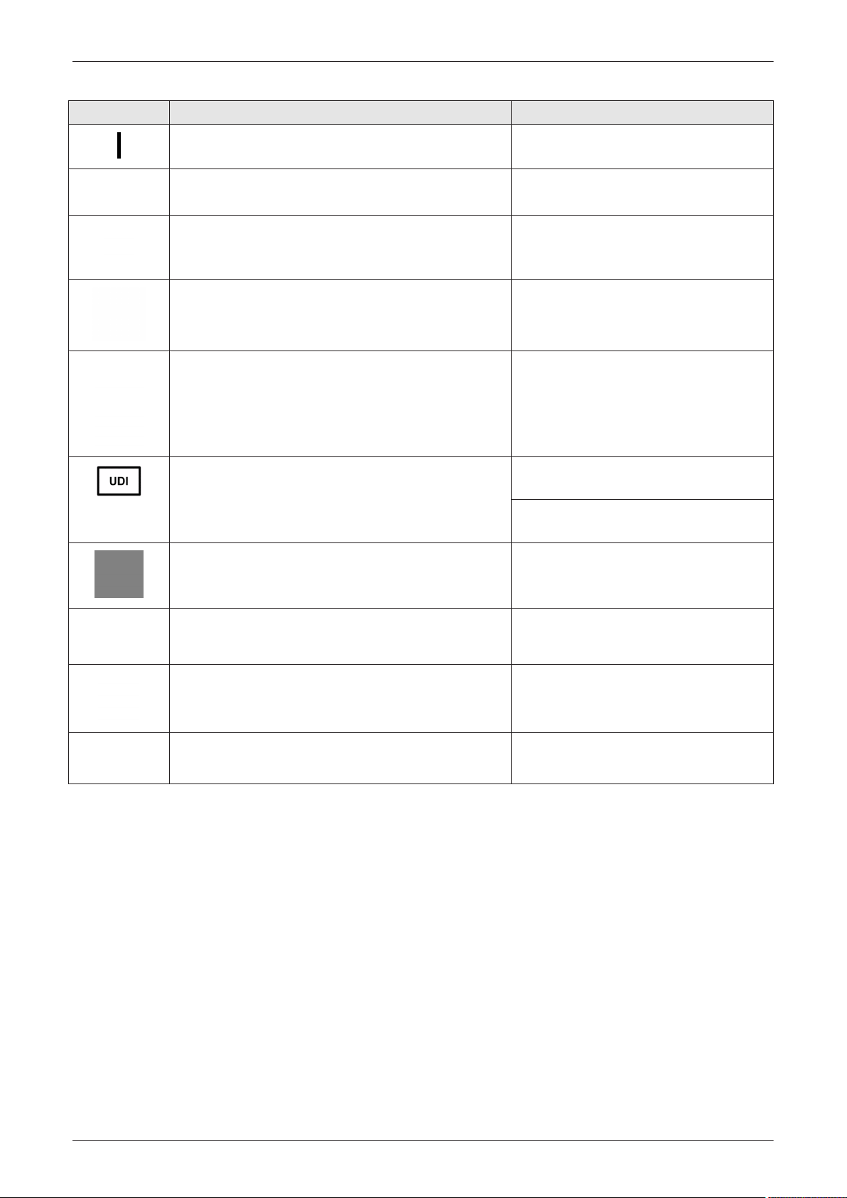
Introduction
LABEL/SYMBOL PURPOSE/MEANING LOCATION
"Mains ON" Indicates the power on position of the mains power
switch.
"Protective Earth" Indicates the protective earth (grounding)
terminal.
"Equipotential" Indicates the terminal to be used for connecting
equipotential conductors when interconnecting (grounding) with
other equipment.
This symbol indicates that the device is equipped with hardware
for using Continuous Wave Doppler.
These symbols indicate that the product contains hazardous
materials in excess of the limits established by the Chinese
standard GB/T 26572 Requirements of concentration limits for
certain restricted substances in electrical and electronic products.
Every system has a unique marking for identification, the Unique
Device Identification (UDI) Label. The UDI label consists of a
series of (alpha-) numeric characters and barcode which uniquely
identify the Voluson E-Series system as a medical device
manufactured by General Electric.
rear of system at mains switch
(on power supply RSP)
rear of system at mains switch
(on power supply RSP)
rear of system at mains switch
(on power supply RSP)
rear side of the system
rear side of the system
on the plug of each probe
Identification and Rating Plate
(rear side of the system / on plug of each probe)
Upgraded systems
adjacent to the Rating Plate
Product was refurbished / manufactured by GE Healthcare Austria
GmbH & Co OG.
The Common Mark of Products Circulation certifies that the
products bearing this mark, passed all conformity assessment
(approval) procedures.
Mark of conformity with the Technical Regulations. This product
meets the requirements of the Technical Regulations on medical
devices, approved by Resolution No. 753 of the Cabinet of
Ministers of Ukraine of 2 October 2013.
This symbol indicates that the device is a Medical Device.
1.5 Safety Considerations
Content in this section
1.5.1 Introduction - - - - - - - - - - - - - - - - - - - - - - - - - - - - - - - - - - - - - - - - - - - - - - - - - - - 1-21
1.5.2 Human Safety - - - - - - - - - - - - - - - - - - - - - - - - - - - - - - - - - - - - - - - - - - - - - - - - - 1-21
1.5.3 Mechanical Safety - - - - - - - - - - - - - - - - - - - - - - - - - - - - - - - - - - - - - - - - - - - - - - 1-22
1.5.4 Electrical Safety - - - - - - - - - - - - - - - - - - - - - - - - - - - - - - - - - - - - - - - - - - - - - - - - 1-23
1.5.5 Auxiliary Devices Safety - - - - - - - - - - - - - - - - - - - - - - - - - - - - - - - - - - - - - - - - - - 1-23
1.5.6 Labels Locations - - - - - - - - - - - - - - - - - - - - - - - - - - - - - - - - - - - - - - - - - - - - - - - 1-25
1.5.7 Dangerous Procedure Warnings - - - - - - - - - - - - - - - - - - - - - - - - - - - - - - - - - - - - 1-25
1.5.8 Lockout/Tagout (LOTO) Requirements - - - - - - - - - - - - - - - - - - - - - - - - - - - - - - - 1-26
1.5.9 Returning/Shipping System, Probes and Repair Parts - - - - - - - - - - - - - - - - - - - - - 1-26
rear of system
Identification and Rating Plate
(rear side of the system)
Identification and Rating Plate
(rear side of the system)
Identification and Rating Plate
(rear side of the system)
1-20
Voluson E-Series Proprietary Service Manual
5539549APB Revision 8
Page 39

1.5.1 Introduction
The following safety precautions must be observed during all phases of operation, service and repair of this
equipment. Failure to comply with these precautions or with specific warnings elsewhere in this manual,
violates safety standards of design, manufacture and intended use of the equipment.
1.5.2 Human Safety
Operating personnel must not remove the system covers.
•
Servicing should be performed by authorized personnel only.
•
Only personnel who have participated a Voluson E-Series training are authorized to service the equipment.
Danger
Dangerous voltages, capable of causing death are present in this system. Use extreme caution when
handling, testing and adjusting.
Warning
Do not operate the system in an explosive atmosphere. Operation of any electrical equipment in such an
environment constitutes a definite safety hazard.
Warning
Because of the limited access to cabinets and equipment in the field, placing people in awkward positions,
GE has limited the lifting weight for one person in the field to 16 KG (35 LBS). Anything over 16 KG (35 LBS)
requires 2 people.
Introduction
Warning
If the covers are removed from an operating Voluson E-Series, some metal surfaces may be warm enough
to pose a potential heat hazard if touched, even while in shutdown mode.
Warning
Do not substitute parts or modify the system. Because of the danger of introducing additional hazards, ONLY
install GE Healthcare Austria GmbH & Co OG approved parts. DO NOT perform any unauthorized
modification of the system.
Warning: Risk of electrical shock
Beware that the main power supply, extended power shutdown and BackEnd processor may be energized
even if the power is turned off when the cord is still plugged into the AC outlet.
Ensure that the system is turned off and disconnected from power source.
•
Wait for at least 20 seconds for capacitors to discharge as there are no test points to verify isolation.
•
The amber light on the control console ON/OFF button will turn off.
Warning
Use extreme caution as long as the Voluson E-Series is un-stable, not resting on all four caster wheels.
Warning
Use all Personal Protection Equipment (PPE) such as gloves, safety shoes, safety glasses, and kneeling
pad, to reduce the risk of injury.
Warning
Beware of possible sharp edges on all mechanical parts. If sharp edges are encountered, the appropriate
PPE should be used to reduce the risk of injury.
Warning
Wear all PPE including gloves as indicated in the chemical Material Safety Data Sheet (MSDS).
An optional veterinary/animal use kit is available.
Do not cross-use the Voluson E-Series ultrasound system between human use and veterinary use.
Voluson E-Series Proprietary Service Manual
5539549APB Revision 8
1-21
Page 40
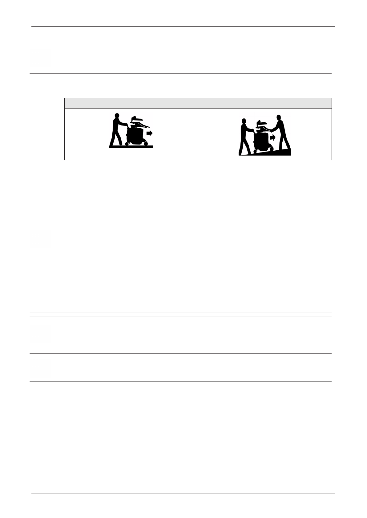
Introduction
Caution: veterinary/animal use
When performing replacement procedures within a veterinary environment, return any used/unused spare
parts with the purple scrap marking label (regardless of the actual condition of the part). Add description on
the label stating that the items were removed from a veterinary environment.
1.5.3 Mechanical Safety
Moving the system on plains Moving the system on inclines
Caution
The Voluson E-Series systems weighs 150 kg or more, depending on installed peripherals, (330 lbs., or
more) when it´s ready for use.
Be careful when moving the system. Two people are required when moving the Voluson E-Series on inclines
or lifting more than 16 kg (35 lbs).
Always lower and center the control console (UI) to its minimum height and lock it in its parking
•
(locked) position.
Secure the monitor and accessories for transport. (Lock the monitor arm and flap down the LCD
•
monitor).
Use the rear handle to move the system.
•
Remove all obstacles.
•
Move the system slowly and carefully in forward direction.
•
Avoid collisions with walls or door frames.
•
Always place the system on horizontal ground and engage the caster brakes.
•
Do not move the system when the brakes are engaged.
•
Move the system forward or backward when going up or down inclines. Do not move the system
•
sideways or diagonally.
Failure to follow the precautions could result in injury, uncontrolled motion and costly damage.
Note
1-22
Warning
Ultrasound systems and probes are highly sensitive medical instruments that can easily be damaged by
improper handling. Use care when handling and protect from damage also when not in use. Do not use a
damaged or defective ultrasound system or probe. Failure to follow these precautions can result in serious
injury and system damage.
Warning
Never use a probe that has fallen to the floor. Even if it looks OK, it may be damaged.
Special care should be taken when transporting the system in a vehicle:
Eject any DVD/CD from the drive.
•
Place the probes in their carrying cases.
•
DO NOT use the control console as an anchor point.
•
Secure the system with straps in an upright position and lock the caster wheels (brake).
•
Ensure that the Voluson E-Series system is firmly secured while inside the vehicle.
•
Drive cautiously to prevent vibration damage.
•
Voluson E-Series Proprietary Service Manual
5539549APB Revision 8
Page 41

1.5.4 Electrical Safety
1.5.4.1 Safe Practices
Follow these guidelines to minimize electrical shock hazards whenever using the system:
To minimize electrical shock hazard, the equipment chassis must be connected to an electrical ground.
•
The system is equipped with a three-conductor AC power cable. This must be plugged into an
•
approved electrical outlet with safety ground.
The power outlet used for this equipment should not be shared with other types of equipment.
•
Both the system power cable and the power connector must meet international electrical standards.
•
Warning
Connecting a Voluson E-Series system to the wrong voltage level will most likely destroy it.
1.5.4.2 Probes
All probes for Voluson E-Series systems are designed and manufactured to provide trouble-free, reliable
service. To ensure this, correct handling of probes is important, and the following points should be noted:
Do not drop a probe or strike it against a hard surface, as this may damage the probe elements,
•
acoustic lens, or housing.
Inspect the probe prior to each use for damage or degradation to the housing, cable strain relief, lens,
•
seal, connector pins and locking mechanism.
Do not use a cracked or damaged probe. In this event, call your field service representative
•
immediately to obtain a replacement.
Avoid pulling, pinching or kinking the probe cable, since a damaged cable may compromise the
•
electrical safety of the probe.
Never immerse the probe connector or adapter into any liquid.
•
The system has more than one type of probe port. Use the appropriate probe port designed for the
•
probe you are connecting.
Introduction
Note
For detailed information on handling probes, refer to the Voluson E-Series Basic User Manual resp.
Instructions for Use and the Care Card supplied with the probe.
1.5.5 Auxiliary Devices Safety
Caution
Power supplies for additional equipment MUST comply with IEC 60601-1.
Caution
Do not attempt to use different peripherals and accessories (brand and model; connected via USB port)
other than approved and provided by GE Healthcare Austria GmbH & Co OG! The Voluson E-Series
ultrasound system is an extremely sensitive and complex medical system. Any unauthorized peripherals may
cause system failure or damage.
Voluson E-Series systems are equipped with an isolation transformer to provide the required separation from
AC mains for both, the system and the auxiliary devices. One AC mains power outlet is located at the power
supply. It is used for connecting the threefold/fourfold splitter whose outlets are led to the shelves, intend for
auxiliary devices (e.g., printers).
At systems with "serial" EC350 (BT20) hardware, just one single AC power outlet (e.g., for Color printer) +
one 12Volt DC power outlet (for the Black and White printer) is led to the shelves for auxiliary devices.
The IEC60601 standard provides a guideline for safely interconnecting medical devices in systems.
“Equipment connected to the analog or digital interface must comply with the respective IEC standards (e.g.
IEC60950 for data processing equipment and IEC60601-1 for medical equipment).
Everybody who connects additional equipment to the signal input portion or signal output portion configures
a medical system and is therefore responsible that the system complies with the requirements of the system
standard IEC60601.
Voluson E-Series Proprietary Service Manual
5539549APB Revision 8
1-23
Page 42
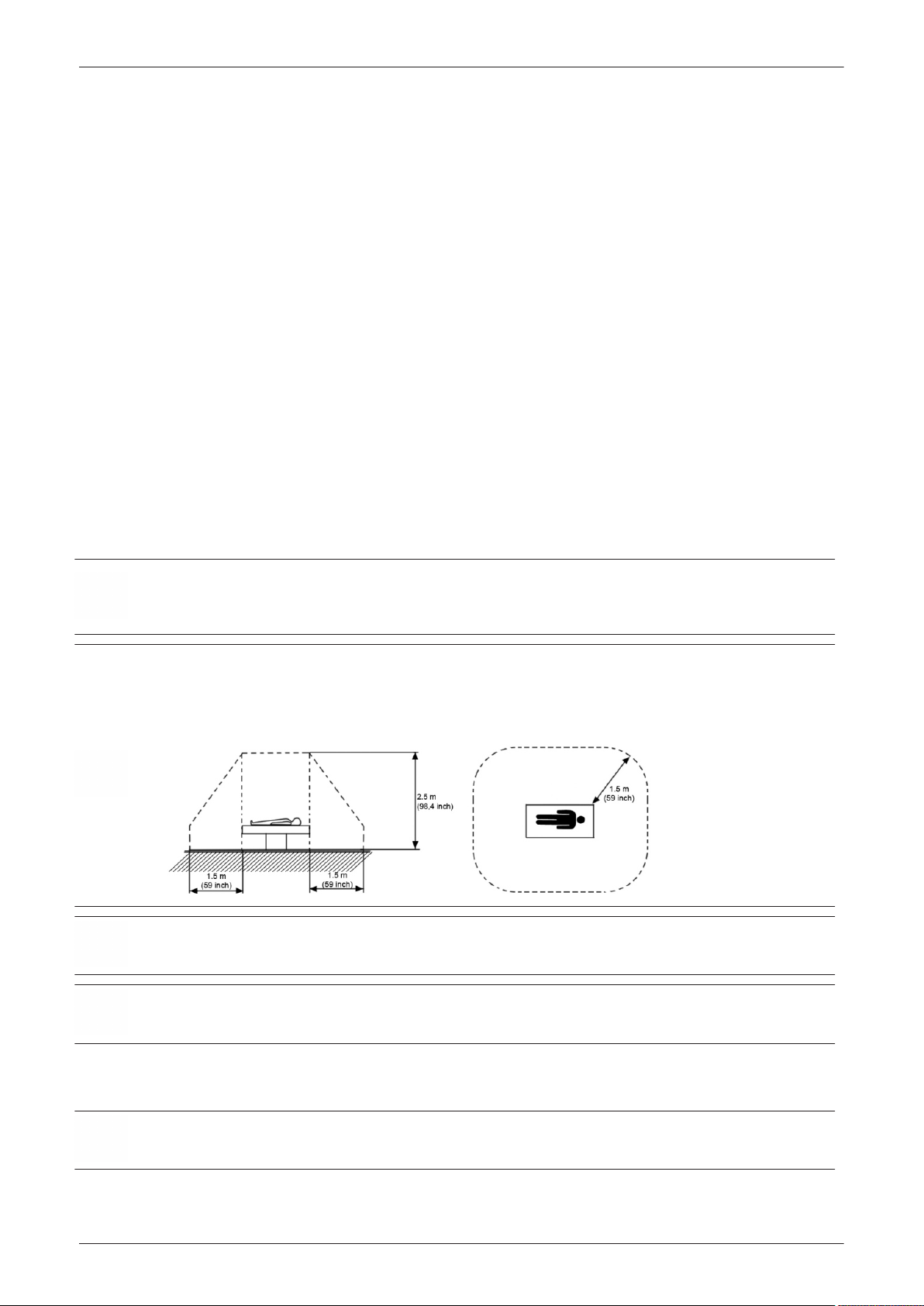
Introduction
Note
1. The medical device may be connected to a single IEC XXX device (protection class I) placed in a room
which is not medically used.
If the device is to be connected in a medically-used room the following rule applies:
2.
-
IEC XXX compliant devices (protection class I) may be connected with an additional safety
measure.
-
IEC 60601 compliant devices may be connected as such.
For all situations 1 and 2, the additional device shall be installed outside the typical patient environment.
Possible additional safety measures are additional protective earth connection between the 2 devices, or a
safety isolation mains transformer for the other device.
Special care must be taken, if the device is connected to computer network (e.g., Ethernet), because other
devices could be connected without any control. There could be a potential difference between the protective
earth and any line of the computer network including the shield.
In this case the only way to operate the system safely is to use an isolated signal link with minimum air
clearance and creepage distance of the isolation device in agreement with IEC60601 incl. national
deviations. For computer networks there are media converters available which convert the electrical to
optical signals. Please consider that this converter must comply with IEC xxx standards* and is battery
operated or connected to the isolation mains output of the Voluson E-Series ultrasound system.
* IEC xxx stands for standards such as:
IEC60601 for medical devices
•
IEC60950 for information technology equipment etc.
•
The system integrator (any person connecting the medical device to other devices) is responsible that
connections are safe. If in doubt, consult the technical service department or your local representative.
Caution
The leakage current of the entire system including any / all auxiliary equipment must not exceed the limit
values as per EN60601-1-1 (IEC60601-1-1) respectively other valid national or international standards. All
equipment must comply with CSA, IEC or other relevant requirements.
Caution
Please observe that some printers may not be medical devices! If Bluetooth-, Line- or Laser Printers are no
medical devices, they have to be located outside of the typical patient environment. Examples for typical
patient environments can be found in standard IEC 60601 (see illustrations below).
Caution
Auxiliary equipment must only be connected with the special main outlet provided for the electrical safety of
the system.
Caution
Auxiliary equipment with connection to AC Mains requires galvanic separation of the signal and/or control
leads.
Note
Note
1-24
Always observe the instructions given in the manual of the peripheral/auxiliary device.
For hardware installation procedures see:
Warning
After each installation, the leakage currents have to be measured according to IEC 60601-1, IEC 62353 or
other relevant standard.
Chapter 3 – Setup Instructions
All peripherals mounted on the Voluson E-Series system chassis must be firmly secured in position.
Voluson E-Series Proprietary Service Manual
5539549APB Revision 8
Page 43

1.5.6 Labels Locations
The Voluson E-Series ultrasound system comes equipped with product labels and icons. These labels and
icons represent pertinent information regarding the operation of the system.
Introduction
Note
For description of all symbols and labels used in combination with this Voluson E-Series ultrasound system,
refer to Section 1.4.3 on page 1-18 and Chapter 2 in the Basic User Manual of your system.
1.5.6.1 Identification and Rating Plate
The Identification and Rating Plate is located on the rear of the Voluson E-Series system.
The layout of the Identification and Rating Plate depends on BT-version and/or date of manufacture.
Figure 1-1 Identification and Rating Plate: Examples
1 Manufacturer 8 Safety type: Type BF 15 Mark of conformity - Ukraine
2 Model Type 9 WEEE Disposal Icon 16 UDI label (barcode and characters)
3 System Voltage range 10 TUEV NRTL Certification mark 17 EAC label
4 Power Consumption nominal 11 CE Conformity mark 18 GOST-R label
5 System Serial Number 12 FDA Guidance 19 Brand and model, BT version
6 Manufacturing date 13 Hg label 20 Part number
7 Frequency 14 approx. weight of the system 21 Medical Device
22 electronic Instructions for Use
1.5.7 Dangerous Procedure Warnings
Warnings, such as the examples below, precede potentially dangerous procedures throughout this manual.
Instructions contained in the warnings must be followed.
Danger
Dangerous voltages, capable of causing death are present in this system. Use extreme caution when
handling, testing and adjusting.
Warning
If the covers are removed from an operating Voluson E-Series, some metal surfaces may be warm enough
to pose a potential heat hazard if touched, even while in shutdown mode.
Warning
Do not operate the system in an explosive atmosphere. Operation of any electrical equipment in such an
environment constitutes a definite safety hazard.
Warning
Do not substitute parts or modify the system. Because of the danger of introducing additional hazards, ONLY
install GE Healthcare Austria GmbH & Co OG approved parts. DO NOT perform any unauthorized
modification of the system.
Voluson E-Series Proprietary Service Manual
5539549APB Revision 8
1-25
Page 44

Introduction
1.5.8 Lockout/Tagout (LOTO) Requirements
Follow OSHA Lockout/Tagout requirements (USA) or local Lockout/Tagout requirements by ensuring you are
in total control of the AC power plug at all times during the service process.
To apply Lockout/Tagout (LOTO):
Plan and prepare for shutdown.
1.
2. Shutdown the equipment.
3. Isolate the equipment.
4. Apply Lockout/Tagout Devices.
5. Control all stored and residual energy.
6. Verify isolation.
All potentially hazardous stored or residual energy is relieved.
Warning
Energy Control and Power Lockout for Voluson E-Series:
When servicing parts of the system where there is exposure to voltage greater than 30 Volts:
Follow LOTO (Lockout/Tagout) procedures.
1.
2. Turn off the breaker.
3. Unplug the Voluson E-Series system.
4. Maintain control of the Voluson E-Series system power plug.
5. Wait for at least 30 seconds for capacitors to discharge as there are no test points to verify isolation.
Ultrasound system components may be energized.
1.5.9 Returning/Shipping System, Probes and Repair Parts
When returning or shipping the Voluson E-Series system in the original packaging:
system must be lowered to its minimum height with monitor flapped down
•
the control console must be centered and locked in “unextended” position
•
Note
Note
Note
For control console positioning see Section 6.3 on page 6-5 .
Equipment being returned must be clean and free of blood and other infectious substances.
GE policy states that body fluids must be properly removed from any part or equipment prior to shipment. GE
employees, as well as customers, are responsible for ensuring that parts/equipment have been properly
decontaminated prior to shipment. Under no circumstance should a part or equipment with visible body fluids
be taken or shipped from a clinic or site (for example, body coils or and ultrasound probe).
The purpose of the regulation is to protect employees in the transportation industry, as well as the people
who will receive or open this package.
The US Department of Transportation (DOT) has ruled that “items what were saturated and/or dripping with
human blood that are now caked with dried blood; or which were used or intended for use in patient care”
are “regulated medical waste” for transportation purpose and must be transported as a hazardous material.
The user/service staff should dispose of all the waste properly, per federal, state, and local waste disposal
regulations.
The Voluson E-Series system is not meant to be used for long-term storage of patient data or images. The
user is responsible for the data on the system and a regular backup is highly recommended.
If the system is sent for repair, please ensure that any patient information is backed up and erased from the
system before shipping. It is always possible during system failure and repair to lose patient data. GE is not
responsible for the loss of this data.
If PHI (Patient Healthcare Information) data needs to be sent to GE employees for service purposes, GE will
ascertain agreement from the customer. Patient information shall only be transferred by approved service
processes, tools and devices restricting access, protecting or encrypting data where required, and providing
traceability in the form of paper or electronic documents at each stage of the procedure while maintaining
compliance with cross-border restrictions of patient information transfers.
1-26
Voluson E-Series Proprietary Service Manual
5539549APB Revision 8
Page 45

1.6 EMC, EMI and ESD
1.6.1 What is EMC?
Electromagnetic compatibility describes a level of performance of a device within its electromagnetic
environment. This environment consists of the device itself and its surroundings including other equipment,
power sources and persons with which the device must interface. Inadequate compatibility results when a
susceptible device fails to perform as intended due interference from its environment or when the device
produces unacceptable levels of emission to its environment. This interference is often referred to as radio–
frequency or electromagnetic interference (RFI/EMI) and can be radiated through space or conducted over
interconnecting power of signal cables. In addition to electromagnetic energy, EMC also includes possible
effects from electrical fields, magnetic fields, electrostatic discharge and disturbances in the electrical power
supply.
For applicable standards please refer to Chapter 2 in the Basic User Manual of the Voluson E-Series
ultrasound system.
1.6.2 Compliance
The Voluson E-Series system conforms to all applicable conducted and radiated emission limits and to
immunity from electrostatic discharge, radiated and conducted RF fields, magnetic fields and power line
transient requirements as mentioned in IEC60601-1-2.
Introduction
Note
For CE Compliance, it is critical that all covers, screws, shielding, gaskets, mesh, clamps, are in good
condition, installed tightly without skew or stress. Proper installation following all comments noted in this
service manual is required to achieve full EMC performance.
1.6.3 Electrostatic Discharge (ESD) Prevention
Warning
DO NOT touch any boards with integrated circuits prior to taking necessary ESD precautions.
When installing boards, ESD may cause damage to a board. ALWAYS connect yourself, via an arm-
1.
wrist strap, to the advised ESD connection point located on the rear of the system (to the right of the
power connector).
2. Follow general guidelines for handling of electrostatic sensitive equipment.
Warning: Risk of electrical shock! System must be turned off.
Avoid all contact with electrical contacts, conductors and components.
Always use non-conductive handles designed for the removal and replacement of ESD sensitive parts. All
parts that have the potential for storing energy must be discharged or isolated before making contact.
Voluson E-Series Proprietary Service Manual
5539549APB Revision 8
1-27
Page 46
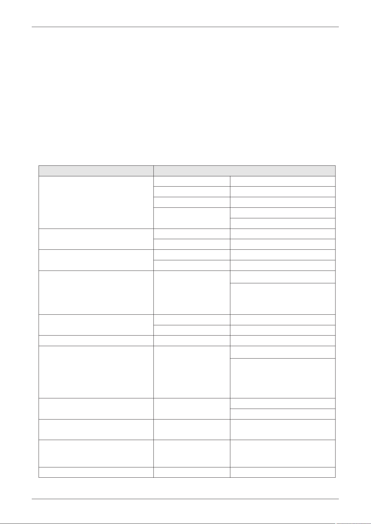
Introduction
1.7 Customer Assistance
1.7.1 Contact Information
If the system does not work as indicated in this service manual or in the Basic User Manual, or if you require
additional assistance, please contact the local distributor or appropriate support resource, as listed below.
Note
USA
GE Medical Systems
Ultrasound Service Engineering
9900 Innovation Drive (RP-2123)
Wauwatosa, WI 53226, USA
Canada
Latin America
Europe
GE Ultraschall Deutschland GmbH
Beethovenstraße 239
Postfach 11 05 60, D-42655 Solingen
Germany
EGM
Africa Algeria Service Center Tel: +213 2179 1212
Asia (Singapore)
GE Ultrasound Asia
Service Department - Ultrasound
298 Tiong Bahru Road #15-01/06
Central Placa
Singapore 168730
Japan Online Center
China Technical Support
India Technical Support Tel: 1800-425-8025
Korea Technical Support Tel: +(82) 1544-6119
Collect vital system information (see: Section 7.1 on page 7-2 ) before you call:
System Type
•
System Serial number (also visible on label on back of the system)
•
Application Software version
•
Backup version
•
additional information about installed software
•
Table 1-7 phone numbers for customer assistance
Location Phone Number
Service Tel: 1-800-437-1171
Service Parts Tel: 1-800-558-2040
Online Center Tel: 1-800-321-7937
Application Support
Service Tel: 1-800-668-0732
Application Support Tel: 1-262-524-5698
Service Tel: +1-262-524-5300
Application Support Tel: +1-262-542-5698
Support
Saudi Arabia Service Center Tel: (+966) 800 429 2222
UAE Service Center Tel: +971 800 3646
Service Department
Tel: 1-800-682-5327
Tel: 1-262-542-5698
Tel: +49 (0) 212-2802-652
Fax: +49 (0) 212-2802-4331
Tel: +65 6291-8528
Fax: +65 6291-7006
Tel: +81 42-846-9011
Fax + 81 42-648-2905
Tel: +(86) 400-812-8188
Tel: +(86) 800-810-8188
Tel: 1800-425-7255
Tel: 1800-102-7750
1-28
Voluson E-Series Proprietary Service Manual
5539549APB Revision 8
Page 47
Location Phone Number
ANZ Service Support Tel: +(61) 1-800-659-465
Australia Service Support Tel: +(61) 1-800-659-465
1.7.2 System Manufacturer
Table 1-8 system manufacturer
Manufacturer Telephone FAX
GE Healthcare Austria GmbH & Co OG Austria
GmbH & Co OG
Tiefenbach 15
A-4871 Zipf
Austria - Europe
+43 (0) 7682-3800-0 +43 (0) 7682-3800-47
Introduction
Voluson E-Series Proprietary Service Manual
5539549APB Revision 8
1-29
Page 48

Introduction
This page was intentionally left blank.
1-30
Voluson E-Series Proprietary Service Manual
5539549APB Revision 8
Page 49

Chapter 2
Site Preparation
This chapter provides the information required to plan and prepare for the
installation of a Voluson E-Series system. Included are descriptions of the facility
and electrical needs to be met by the purchaser.
Content in this chapter
2.1 General Requirements - - - - - - - - - - - - - - - - - - - - - - - - - - - - - - - - - - - - - - - 2-2
2.2 Facility Needs - - - - - - - - - - - - - - - - - - - - - - - - - - - - - - - - - - - - - - - - - - - - - 2-6
Voluson E-Series Proprietary Service Manual
5539549APB Revision 8
2-1
Page 50

Site Preparation
2.1 General Requirements
2.1.1 Environmental requirements
Table 2-1 environmental requirements
Operating Temperature Operating Humidity Heat Dissipation Storage Temperature Storage Humidity
10 to 30°C
(50 to 86°F)
Caution
If the system has been in storage, transported or is very cold or hot, do not turn on its power until it has had
a chance to acclimate to its operating environment. (see:
30 to 80% rH
non-condensing
2.1.1.1 Cooling
The cooling requirement for a Voluson E-Series system is 2730 BTU/hour. This figure does not include
cooling needed for lights, people, or other equipment in the room.
Note
Each person in the room places an additional 300 BTU/h demand on the cooling system.
2.1.1.2 Lighting
Bright light is needed for system installation, updates and repairs. However, operator and patient comfort
may be optimized if the room light is subdued and indirect. Therefore, a combination lighting system (dim/
bright) is recommended. Keep in mind that lighting controls and dimmers can be a source of EMI which
could degrade image quality. These controls should be selected to minimize possible interference.
2.1.2 Electrical Requirements
Note
GE Healthcare Austria GmbH & Co OG requires a dedicated power and ground for the proper operation of
its Ultrasound equipment. This dedicated power shall originate at the last distribution panel before the
system.
The Ultrasound will function on voltages from 100-240 Volts and 50 or 60 Hz. However, if using 220 volt
power in North America, then a center tapped power source is required.
Sites with a mains power system with defined Neutral and Live:
The dedicated line shall consist of one phase, a neutral (not shared with any other circuit), and a full size
ground wire from the distribution panel to the ultrasound outlet.
Sites with a mains power system without a defined Neutral:
The dedicated line shall consist of one phase (two lines), not shared with any other circuit, and a full size
ground wire from the distribution panel to the ultrasound outlet.
2730 BTU/hour
-10 to 50°C
(14 to 122°F)
< 90% rH non-
condensing
"System Acclimation Time" on page 3-3
).
Note
Please note that image artifacts can occur, if at any time within the facility, the ground from the main facility's
incoming power source to the ultrasound system is only a conduit.
2.1.2.1 Voluson Power Requirements Voluson E-Series
Table 2-2 electrical specifications for Voluson E-Series
Voltage Tolerances Power Consumption Frequency
100 - 240 VAC ±10% 800 VA 50, 60 Hz (±2%)
AC mains power outlets (AUX) for auxiliary devices and peripherals are co-switched by the systems mains
switch. Output voltage for AUX: 115V (EC300-EC340) resp. 100V - 240V (EC350)
Caution
The maximum power consumption of equipment (inclusive color LCD monitor) connected to these outlets
must not exceed 200 VA!
2-2
Voluson E-Series Proprietary Service Manual
5539549APB Revision 8
Page 51

2.1.2.2 Inrush Current
Inrush current is not a factor to consider due to the inrush current limiting properties of the power supplies.
2.1.2.3 Site Circuit Breaker
It is recommended that the branch circuit breaker for the system be readily accessible.
Caution: Power outage may occur.
Voluson E-Series requires a dedicated single branch circuit. To avoid circuit overload and possible loss of
critical care equipment, make sure you DO NOT have any other equipment operating on the same circuit.
2.1.2.4 Site Power Outlets
A dedicated AC power outlet must be within reach of the system without extension cords. Other outlets
adequate for the external peripherals, medical and test equipment needed to support this system must also
be present within 1 m (3.2 ft.) of the system. Electrical installation must meet all current local, state, and
national electrical codes.
2.1.2.5 System Power Plug
If the Voluson E-Series arrives without a power plug, or with the wrong plug, you must contact your GE
dealer or the installation engineer must supply what is locally required.
Site Preparation
2.1.3 EMI Limitations
Ultrasound systems are susceptible to Electromagnetic Interference (EMI) from radio frequencies, magnetic
fields, and transients in the air or wiring. They also generate EMI. The Voluson E-Series system complies
with limits as stated on the EMC label. However, there is no guarantee that interference will not occur in a
particular installation.
Note
Possible EMI sources should be identified before the system is installed.
Electrical and electronic equipment may produce EMI unintentionally as the result of a defect. Sources of
EMI include the following:
medical lasers
•
scanners
•
cauterizing guns
•
computers
•
monitors
•
fans
•
gel warmers
•
microwave oven
•
light dimmers
•
mobile phones
•
in-house wireless phones (DECT phones)
•
wireless computer keyboard and mouse
•
air conditioning system
•
High Frequency (HF) surgery equipment
•
general AC/DC adapters
•
The presence of a broadcast station or broadcast van may also cause interference.
Voluson E-Series Proprietary Service Manual
5539549APB Revision 8
2-3
Page 52
Site Preparation
Table 2-3 EMI prevention/abatement
EMI Rule Details
Be aware of Radio
Frequency sources.
Ground the system. Poor grounding is the most likely reason a system will have noisy images. Check grounding of the
Assemble all screws, Radio
Frequency gaskets, covers
and cores.
Replace broken Radio
Frequency gaskets.
Do not place labels where
Radio Frequency gaskets
touch metal.
Use GE- specified harnesses
and peripherals.
Take care with cellular
phones.
Properly route peripheral
cables.
Keep the system at least 5 meters (15 feet) away from other EMI sources. Special shielding may be
required to eliminate interference problems caused by high frequency, high powered radio or video
broadcast signals.
power cord and power outlet.
After you finish repairing or updating the system, assemble all covers and tighten all screws. Any
cable with an external connection requires a magnet wrap at each end. Install all covers. Loose or
missing covers or Radio Frequency gaskets allow radio frequencies to interfere with the ultrasound
signals.
If more than 20% or a pair of the fingers on an Radio Frequency gasket are broken, replace the
gasket. Do not turn ON the system until any loose metallic part is removed.
Never place a label where Radio Frequency gaskets meet the system. Otherwise, the gap created
will permit Radio Frequency leakage. In case a label has been found in such a position, move it to
another more suitable location.
The interconnect cables are grounded and require ferrite beads and other shielding. Also, cable
length, material, and routing are all important; do not change from what is specified.
Cellular phones may transmit a 5 V/m signal; that could cause image artifacts.
Do not allow cables to lie across the top of the card rack or hang out of the peripheral bays. Loop the
excess length for peripheral cables inside the peripheral bays. Attach the monitor cables to the
frame.
2.1.4 Environmental Requirements for Probes
Probes can be used in clinical environment.
Ensure that the probe face temperature does not exceed the normal operation temperature range.
Probes must be operated, stored, or transported within the parameters outlined below.
Operational Storage Transport
Temperature
Humidity
Pressure
+18º to +30º C
(+64.4°F to +86°F)
30% to 75% RH non-
condensing
700hPa (3000m) to
1060hPa
2.1.5 Time and Manpower Requirements
Site preparation takes time. Begin site preparation checks as soon as possible. If possible, six weeks before
delivery, to allow enough time to make any changes.
Warning
Have two people available to deliver and unpack the Voluson E-Series ultrasound system.
Attempts to move the system considerable distances (or on an incline) by one person alone, could result in
personal injury and/or damage to the system.
-10º to +50º C
(+14°F to +122°F)
10% to 85% RH non-
condensing
700hPa (3000m) to
1060hPa
-10º to +50º C
(+14°F to +122°F)
10% to 85% RH non-
condensing
700hPa (3000m) to
1060hPa
2-4
Voluson E-Series Proprietary Service Manual
5539549APB Revision 8
Page 53

2.1.6 System Specifications
2.1.6.1 Physical Dimensions of Voluson E-Series
Physical dimensions and weight (without peripherals) of the Voluson E-Series system are summarized in
Table 2-4
.
Site Preparation
Note
Physical dimensions (especially height and depth) depend on control console and monitor positioning.
For more details see Section 5.10.3 "Control Console Positioning" on page 5-95 .
Table 2-4 physical dimensions and weight (without monitor and peripherals)
Height Width Depth Weight
1533 mm / 60.4 inch *
1333 mm / 52.5 inch **
* maximum at “normal” monitor position (control console is lifted and moved forwards to the maximum)
** minimum at “normal” monitor position (no control console lifted or forwards movement)
2.1.6.2 Acoustic Noise Output
max. 60 dB(A)
2.1.6.3 Electrical Specifications
Refer to:
Section 2.1.2.1 "Voluson Power Requirements Voluson E-Series" on page 2-2
582 mm / 22.9 inch 1168 mm / 46.0 inch *
968 mm / 38.1 inch **
150 kg / 330 lbs.
.
Voluson E-Series Proprietary Service Manual
5539549APB Revision 8
2-5
Page 54

Site Preparation
2.2 Facility Needs
2.2.1 Purchaser Responsibilities
The work and materials needed to prepare the site is the responsibility of the purchaser. Delay, confusion,
and waste of manpower can be avoided by completing pre-installation work before delivery.
Use the Pre-installation checklist (provided in
Table 2-5 Voluson E-Series pre-installation checklist
Action Yes No
Schedule at least 3 hours for installation of the system.
Notify installation team of the existence of any variances from the basic installation.
Make sure system and probes have been subject to acclimation period.
Environmental cooling is sufficient.
Lighting is adjustable to adapt to varying operational conditions of the system.
Electrical facilities meet system requirements.
EMI precautions have been taken and all possible sources of interference have been removed.
Mandatory site requirements have been met.
If a network is used, IP address has been set for the system and a dedicated network outlet is available.
Table 2-5
) to verify that all needed steps have been taken.
Note
Purchaser responsibility includes:
Procuring the materials required.
•
Completing the preparations before delivery of the ultrasound system.
•
Paying the costs for any alterations and modifications not specifically provided in the sales contract.
•
All electrical installations that are preliminary to the positioning of the equipment at the site prepared for the
equipment must be performed by licensed electrical contractors. Other connections between pieces of
electrical equipment, calibrations, and testing must also be performed by qualified personnel. The products
involved (and the accompanying electrical installations) are highly sophisticated and special engineering
competence is required. All electrical work on these products must comply with the requirements of
applicable electrical codes. The purchaser of GE equipment must only utilize qualified personnel to perform
electrical servicing on the equipment.
The desire to use a non–listed or customer provided product or to place an approved product further from the
system than the interface kit allows presents challenges to the installation team. To avoid delays during
installation, such variances should be made known to the individuals or group performing the installation at
the earliest possible date (preferably prior to the purchase).
The ultrasound suite must be clean prior to delivery of the machine. Carpet is not recommended because it
collects dust and creates static. Potential sources of EMI (electromagnetic interference) should also be
investigated before delivery. Dirt, static, and EMI can negatively impact system reliability.
2-6
Voluson E-Series Proprietary Service Manual
5539549APB Revision 8
Page 55

2.2.2 Required Facility Needs
Site Preparation
Note
Note
dedicated single branch power outlet of adequate amperage (see:
•
local and national codes, which is located less than 2.5 m (8.2 ft. / 98.4 in.) from the system's proposed
location.; see
door opening is at least 76 cm (2.5 ft./ 30 in.) wide
•
proposed location for the system is at least 0.5 m (1.6 ft. / 19.6 in.) from the wall for cooling
•
power outlet and place for any external peripheral are within 2 m (6.5 ft. / 78.7 in.) of each other with
•
peripheral within 1 m of the system to connect cables.
power outlets for other medical equipment
•
power outlets for test equipment within 1 m (3.2 ft. / 39.4 in.) of system
•
clean and protected space to store probes (in their cases or on a rack)
•
material to safely clean probes (done with a plastic container, never metal)
•
The Voluson E-Series has outlets for on-board peripherals inside.
In case of network option:
An active network outlet in the vicinity of the ultrasound system.
•
A network cable of appropriate length (regular Pin-to-Pin network cable).
•
An IT administrator who will assist in configuring the system to work with your local network. A fixed IP
•
address is required. Refer to the form provided in
All relevant preliminary network port installations at the prepared site must be performed by authorized
contractors. The purchaser of GE equipment must utilize only qualified personnel to perform servicing on the
equipment.
Section 2.1.2 "Electrical Requirements" on page 2-2
Figure 3-107
Table 2-2 on page 2-2
.
for network details that are required.
), meeting all
1 door – at least 76 cm (2.5 foot / 30 inches) 8 stool
2 film viewer 9 ultrasound system
3 counter top, sink with hot and cold water, supplies storage 10 external peripherals
4 linen supply 11 dedicated power outlet - circuit breaker protected and
5 probes/supplies 12 network interface
6 examination table 13 distance from wall or objects
7 footswitch 14 cabinet for software and manuals
Voluson E-Series Proprietary Service Manual
5539549APB Revision 8
Figure 2-1 recommended Floor Plan 4.3 m x 5.2 m (14 by 17 foot)
easily accessible
2-7
Page 56

Site Preparation
2.2.3 Desirable Features
door is at least 92 cm (3 ft. / 36 in.) wide
•
circuit breaker for dedicated power outlet is easily accessible
•
sink with hot and cold water
•
receptacle for bio–hazardous waste, like used probe sheaths
•
emergency oxygen supply
•
storage for linens and equipment
•
nearby waiting room, lavatory, and dressing room
•
dual level lighting (bright and dim)
•
lockable cabinet for software and manuals
•
2.2.4 Network Setup Requirements
2.2.4.1 Stand-alone System (without Network Connection)
None
2.2.4.2 System connected to Hospital's Network
Supported networks:
Ethernet network connection
•
Wireless LAN (option)
•
2.2.4.3 Purpose of the DICOM Network Function
DICOM® 1 (Digital Imaging and Communications in Medicine) services provide the operator with clinically
useful features for moving images and patient information over a hospital network. Examples of DICOM
services include the transfer of images to workstations for viewing or transferring images to remote printers.
As an added benefit, transferring images in this manner frees up the on-board monitor and peripherals,
enabling viewing to be done while scanning continues. With DICOM, images can be archived, stored, and
retrieved faster, easier, and at a lower cost.
2.2.4.4 DICOM Option Pre-Installation Requirements
To configure the Voluson E-Series ultrasound system to work with other network connections, the network
administrator must provide some necessary information.
Use the
•
•
•
Figure 3-106 on page 3-97
Voluson E-Series Details: DICOM network details for the Voluson E-Series system, including the
Routing Information: IP addresses for default gateway and other routers in use at site.
DICOM Application
Information:
to record required information that must include:
host name, local port, IP address, AE title and net mask.
Details of DICOM devices in use at the site, including the DICOM host
name, AE title, DICOM port number and IP addresses.
Note
2-8
For further details refer to the Voluson E-Series Basic User Manual resp. Instructions for Use.
1 DICOM is the registered trademark of the National Electrical Manufacturers Association for its standards publications relating to digital communications
of medical information.
Voluson E-Series Proprietary Service Manual
5539549APB Revision 8
Page 57

Chapter 3
Setup Instructions
This chapter contains information needed to setup the Voluson E-Series
ultrasound system. Included are procedures to receive, unpack and configure the
equipment. A worksheet is provided (see: Section 3.14 on page 3-97 ) to help
ensure that all the required information is available, prior to setup the system.
Content in this chapter
3.1 Setup Reminders - - - - - - - - - - - - - - - - - - - - - - - - - - - - - - - - - - - - - - - - - - - 3-2
3.2 Receiving and Unpacking the System - - - - - - - - - - - - - - - - - - - - - - - - - - - - 3-5
3.3 Preparing for Setup - - - - - - - - - - - - - - - - - - - - - - - - - - - - - - - - - - - - - - - - - 3-7
3.4 Completing the Setup - - - - - - - - - - - - - - - - - - - - - - - - - - - - - - - - - - - - - - - - 3-9
3.5 Connection of Auxiliary Devices - - - - - - - - - - - - - - - - - - - - - - - - - - - - - - - - 3-14
3.6 Printer Installation - - - - - - - - - - - - - - - - - - - - - - - - - - - - - - - - - - - - - - - - - - 3-39
3.7 System Configuration - - - - - - - - - - - - - - - - - - - - - - - - - - - - - - - - - - - - - - - 3-61
3.8 On-board optional Peripherals - - - - - - - - - - - - - - - - - - - - - - - - - - - - - - - - - 3-72
3.9 External I/O Connectors - - - - - - - - - - - - - - - - - - - - - - - - - - - - - - - - - - - - - 3-73
3.10 Available Probes - - - - - - - - - - - - - - - - - - - - - - - - - - - - - - - - - - - - - - - - - - 3-77
3.11 Software/Option Configuration - - - - - - - - - - - - - - - - - - - - - - - - - - - - - - - - 3-77
3.12 Connectivity Setup - - - - - - - - - - - - - - - - - - - - - - - - - - - - - - - - - - - - - - - - 3-78
3.13 Network Configuration - - - - - - - - - - - - - - - - - - - - - - - - - - - - - - - - - - - - - - 3-80
3.14 Connectivity Setup Worksheet - - - - - - - - - - - - - - - - - - - - - - - - - - - - - - - - 3-97
3.15 Paperwork - - - - - - - - - - - - - - - - - - - - - - - - - - - - - - - - - - - - - - - - - - - - - - 3-99
Voluson E-Series Proprietary Service Manual
5539549APB Revision 8
3-1
Page 58
Setup Instructions
3.1 Setup Reminders
3.1.1 Average Installation Time
Once the site has been prepared, the average installation time required is shown in Table 3-1 below.
Table 3-1 average installation time
Description Average Installation Time Comments
Unpacking the system 0.5 hours
Installing the system / options / printers 0.5 to 1.5 hours depends on required configuration
DICOM Option (connectivity) 0.5 to 1.5 hours depends on configuration amount
Install InSite 0.5 hours
3.1.2 Installation Warnings
Caution
Since the Voluson E-Series weighs approximately 150 kg (330 lbs.) without peripherals, two people are
required to unpack it.
Warning
There are no operator serviceable components. To prevent shock, do not remove any covers or panels.
Should problems or malfunctions occur, unplug the power cord.
Only qualified service personnel should carry out servicing and troubleshooting.
3.1.2.1 Moving/Lifting the System
Note
How to lift the system:
1 Preparation
2 Remove the footrest/wheel axis cover on the front side of the system: Turn the 4 quick release devices below the footrest 90°
3 Pass a strap through the openings in the footrest metal sheet.
4 Lift the system by the straps and the rear handle.
For important safety considerations see Section 1.5.3 "Mechanical Safety" on page 1-22 .
Disconnect all probes and transport them separately.
•
Disconnect the ECG cable (if applicable) and transport it separately.
•
Ensure all peripheral devices (printer, ...) are firmly fixed within the system or transport them separately.
•
(see:
Figure 8-27 on page 8-28
Caution
Do not pull or lift the system with the front handle of the user interface (control console).
•
Always use a strap to lift the system. Do not grasp the metal sheet with your hands.
•
Move the system forward or backward when going up or down inclines. Do not move the system
•
sideways or diagonally.
).
3-2
Voluson E-Series Proprietary Service Manual
5539549APB Revision 8
Page 59

3.1.2.2 System Acclimation Time
After being transported, the Voluson E-Series system may be very cold or hot. It requires one hour for each
2.5°C increment if it's temperature is below 10°C or above 40°C.
Caution
Equipment damage possibility. Turning the system on without acclimation after arriving at site may cause the
system to be damaged.
°C 60 55 50 45 40 35 30 25 20 15 10 5 0 -5 -10 -15 -20 -25 -30 -35 -40
°F 140 131 122 113 104 96 86 77 68 59 50 41 32 23 14 5 -4 -13 -22 -31 -40
hrs 8 6 4 2 0 0 0 0 0 0 0 2 4 6 8 10 12 14 16 18 20
3.1.2.3 Control Console Positioning
If weight is placed on the control console (UI) in its extended position the system could tip over.
Caution
The system should not be moved with the control console (UI) extended. Move the control console to its
centered and locked position for transport.
Setup Instructions
Table 3-2 Acclimation Time
Caution
Monitor mounting mechanism may break if not properly supported (e.g., with packing foam) during
transportation.
3.1.2.4 Brake Pedal Operation
Caution
If the wheel brakes are engaged, release brake pedals (brakes on wheels under the foot rest) to disengage
the lock, for transportation.
Voluson E-Series Proprietary Service Manual
5539549APB Revision 8
3-3
Page 60
Setup Instructions
3.1.3 Safety Reminders
Danger
When using any test instrument that is capable of opening the AC ground line (i.e., meter's ground switch is
OPEN), DO NOT touch the system!
Caution
To prevent electrical shock, connect the system to a properly grounded power outlet. DO NOT use a three to
two prong adapter. This defeats safety grounding.
Caution
When connecting the optional PE (potential equalization) and/or the optional additional GND (ground cable)
it is mandatory to also use the Power Filter (H48701EL).
Caution: The Voluson E-Series requires all covers!
Do not operate this system unless all board covers and frame panels are securely in place, to ensure safe
operation, optimal system performance and cooling. When covers are removed, EMC and EMI compliance
might be compromised.
For service procedures where the operation of the system is necessary with board covers or frame panels
removed, ensure that there are no EMI sensitive devices in the vicinity of the system. If in doubt, relocate the
system to a different environment where no EMI sensitive devices are in the vicinity.
Caution
Two people should unpack the system because of its weight. Two people are required whenever a part
weighing 16kg (35 lb.) or more must be lifted.
Caution:
Do not wear the ESD wrist strap when you work on live circuits and more than 30 V peak is present.
Caution
If the system is very cold or hot, do NOT turn on its power until it has had sufficient time to acclimate to its
operating environment.
Caution: Operator Manual(s) respectivley Instructions for Use
The User Manual(s) should be fully read and understood before operating the Voluson E-Series. Keep
manuals near the system for reference.
Caution: Acoustic Output hazard
Although the ultrasound energy transmitted from the Voluson E-Series ultrasound system is within FDA
limitations, avoid unnecessary exposure. Ultrasound energy can produce heat and mechanical damage.
Table 3-3 Environmental Labels
3-4
Voluson E-Series Proprietary Service Manual
5539549APB Revision 8
Page 61
3.2 Receiving and Unpacking the System
Setup Instructions
Note
Voluson E-Series incl. peripherals
Please read this section carefully before unpacking the Voluson E-Series ultrasound system and its
(optional) peripherals.
The Voluson E-Series ultrasound system, together with peripherals, probes and accessories are shipped
from the factory in a single durable shipping cardboard which is mounted on a raised wooden platform base.
Caution
Transport only with forklift or stacker truck. During transport pay attention to the point of gravity (“tilt and
drop” indicator)!
Warning
Have two people available to deliver and unpack the Voluson E-Series ultrasound system.
Attempts to move the system considerable distances (or on an incline) by one person alone, could result in
personal injury and/or damage to the system.
Description Height Width Depth Weight*
and accessories
* Weight is approximate and will vary depending upon the supplied peripherals
Before unpacking the system
Inspect the cardboard for visible damage.
•
Inspect the drop and tilt indicator (1) for evidence of accidental shock or tilting during transit.
•
The tilt indicator must not turn
Verify delivery address and remove the packing slip and invoice from the envelope (2) that is located
•
on the front panel of the cardboard.
Remove the unpacking instruction (3) that is located on the side panel of the cardboard.
•
Table 3-4 shipping cardboard -dimensions and weight
1369 mm / 54 inch 780 mm / 30.7 inch 1086 mm / 42.8 inch 190 kg / 419 lbs.
red
.
Voluson E-Series Proprietary Service Manual
5539549APB Revision 8
Figure 3-1 shipping cardboard
3-5
Page 62

Setup Instructions
Note
Note
The device must only be transported in the original packaging cardboard!
It is recommended to keep and store the shipping cardboard and all other packing materials (including the
support foams, anti-static plastic cover, etc.), in case the system has to be moved to a different location.
Unpack the system in such a way that packaging can be reused. For warranty purposes, storage of the
above is required for one year from date of purchase.
If the shipping cardboard is damaged, please inform the GE Healthcare Austria GmbH & Co OG sales
representative immediately.
Unpacking procedure
Unpack the Voluson E-Series ultrasound system and its (optional) peripherals and accessories according to
the provided unpacking instruction.
3-6
Voluson E-Series Proprietary Service Manual
5539549APB Revision 8
Page 63
3.3 Preparing for Setup
3.3.1 Verify Customer Order
After unpacking, it is important to verify that all items ordered by the customer have been received.
1.
Compare all items listed on the packing slip (delivery note) with those received.
Setup Instructions
Note
It is recommended to keep and store the shipping cardboard and all other packing materials (including the
support foams, anti-static plastic cover, etc.), in case the system has to be moved to a different location.
Unpack the system in such a way that packaging can be reused. For warranty purposes, storage of the
above is required for one year from date of purchase.
2. Visually inspect the system components using the following checklist.
Table 3-5 Damage Inspection Checklist - Voluson E-Series system
✓ Step Item Recommended Procedure
1 Rating Plate Enter Serial Number: _________________________ (printed on rating plate, see:
2 System Verify that the Voluson E-Series system is switched OFF and unplugged. Clean the system.
3 Control
Console
4 Probes Check all probes for wear and tear on the lens, cable, and connector. Look for bent or damaged pins on
5 LCD Display Clean the LCD display by gently wiping with a dry, soft, lint-free non-abrasive folded cloth. Inspect the
6 Fans Verify that the system's cooling fans and peripheral fans are operating.
7 Rear Panel Check the rear panel connectors for bent pins, loose connections and loose or missing hardware. Screw
Physically inspect the control console for missing or damaged items. After switching on the system, verify
the proper illumination of all the control console buttons.
the connector and in the connector socket on the system. Verify that the EMI fingers around the probe
connector socket housing are intact. Check the probe locking mechanism and probe switch.
monitor for scratches and raster burn.
all the cable connectors tightly to the connector sockets on the panel. Verify that the labeling is in good
condition.
Figure 1-1 on page 1-25
)
Note
8 Covers Check that all screws are tightly secured in place, that there are no dents or scratches and that no internal
parts are exposed.
9 Peripherals Check and clean the peripherals in accordance with the manufacturer's directions. To prevent EMI or
system overheating, dress the peripheral cables inside the peripheral cover.
10 Power Cord Check the power cord for cuts, loose hardware, tire marks, exposed insulation, or any deterioration. Verify
continuity. Replace the power cord, as required.
Report any items that are missing, back-ordered, or damaged, to your GE Healthcare Austria GmbH & Co
OG sales representative. The contact address is shown in "Contact Information" on page 1-28 .
Voluson E-Series Proprietary Service Manual
5539549APB Revision 8
3-7
Page 64

Setup Instructions
3.3.2 EMI Protection
This system has been designed to minimize the effects of Electro-Magnetic Interference (EMI). Many of the
covers, shields, and screws are provided primarily to protect the system from image artifacts caused by this
interference. For this reason, it is imperative that all covers and hardware are installed and secured before
the system is put into operation.
Ensure that the system is protected from electromagnetic interference (EMI), as follows:
Operate the system at least 15 feet away from equipment that emits strong electromagnetic radiation.
•
Operate the system in an area enclosed by walls, floors and ceilings comprised of wood, plaster or
•
concrete, which help prevent EMI.
Shield the system when operating it in the vicinity of radio broadcast equipment, if necessary.
•
Do not operate mobile phones or other EMI emitting devices in the ultrasound room.
•
Verify that all EMI rules listed are followed.
•
The Voluson E-Series system is approved for use in hospitals, clinics and other environmentally qualified
facilities, in terms of the prevention of radio wave interference. Operation of the ultrasound system in an
inappropriate environment can cause electronic interference to radios and television sets situated near the
medical equipment.
For further details and EMI Prevention/Abatement refer to
Section 2.1.3 "EMI Limitations" on page 2-3
.
3-8
Voluson E-Series Proprietary Service Manual
5539549APB Revision 8
Page 65

3.4 Completing the Setup
Connecting the System to a Power Source
Caution
Prior to connecting the Voluson E-Series system to a power source, verify compliance with all electrical and
safety requirements. Check the power cord to verify that it is intact and of hospital-grade. Products equipped
with a power source (wall outlet) plug should be connected to the fixed power socket that has a protective
grounding conductor. Never use an adapter or converter to connect with a power source plug (for example, a
three-prong to two-prong converter).
Warning
The system's power must be supplied from a separate, properly rated outlet to avoid risk of fire. Refer to
Section 2.1.2.1 "Voluson Power Requirements Voluson E-Series" on page 2-2
power cord should not, under any circumstances, be altered to a configuration rated less than that specified
for the current.
Setup Instructions
for rating information. The
Note
Use only the power cords, cables and plugs provided by or designated by GE Healthcare Austria GmbH &
Co OG to connect the system to the power source.
Caution
Whenever disconnecting the Voluson E-Series system from the electrical outlet, always observe the safety
precautions. First unplug the main power cable from the wall outlet socket, then from the system itself.
Remove by pulling on the cable connector - Do not pull on the cable.
Caution: The Voluson E-Series requires all covers!
Do not operate this system unless all board covers and frame panels are securely in place, to ensure safe
operation, optimal system performance and cooling. When covers are removed, EMC and EMI compliance
might be compromised.
For service procedures where the operation of the system is necessary with board covers or frame panels
removed, ensure that there are no EMI sensitive devices in the vicinity of the system. If in doubt, relocate the
system to a different environment where no EMI sensitive devices are in the vicinity.
3.4.1 Power On / Boot Up
System Power On / BackEnd Processor Boot Up
Connect the main power cable to the back of the system.
1.
2. If not already done, screw on the pull-out protection of the mains power cable with the 2 screws.
3. Connect the main power cable to a hospital grade power outlet with the proper rated voltage. Never
use an adapter that would defeat the safety ground.
Voluson E-Series Proprietary Service Manual
5539549APB Revision 8
3-9
Page 66

Setup Instructions
4. Switch ON the circuit breaker at the rear of the system.
Figure 3-2 Circuit Breaker at rear of system
1 circuit breaker
fuses (2x T10A H/250V)
2
3 connector for main power cable
Note
Note
When AC power is applied to the system, the ON/OFF standby button on the control console illuminates
amber, indicating that the system (including the Back-end Processor) is in standby mode.
5. Hold down the ON/OFF standby button (see:
Figure 3-3 below
) on the control console for ~3 seconds.
The mains outlet of the system for peripheral auxiliary equipment are commonly switched with the ON/OFF
standby button. The power switch of any attached printer(s) needs to be in ON position before starting the
system. However, be aware some auxiliary equipment may switch itself to standby mode (e.g., Color video
printer) and must therefore be switched on separately.
When the ON/OFF standby button on the control console is pressed, the system (including the Backend Processor) starts and the operating system is loaded which then leads to activate the application
software.
The system automatically performs an initialization sequence which includes the following:
-
Loading the operating system.
-
Running a quick diagnostic check of the system.
-
Detecting connected probes
Note
3-10
Figure 3-3 ON/OFF standby button
As soon as the software has been loaded, the system enters 2D-Mode with the probe and application
that were used before the system shutdown.
Total time used for start-up is about 2 minutes.
6. Adjust height and position of the control console as described in
Positioning" on page 6-5
.
Section 6.3 "Control Console
Voluson E-Series Proprietary Service Manual
5539549APB Revision 8
Page 67

3.4.1.1 During a normal boot, you may observe
Power is distributed to peripherals, control console, monitor, FrontEnd and BackEnd processor.
1.
2. The BackEnd processor and rest of the system starts with the sequence listed in following steps:
a. First the BIOS version is shown on the monitor.
BT15 (EC300) / BT16 (EC310): Advantech =
*
BT17 (EC320): Advantech =
*
BT18 (EC330) / BT19 (EC340): Advantech =
*
BT20 (EC350): Advantech =
*
b. Afterward the “Boot Screen” is displayed. (Voluson is highlighted).
GE-MED AF113
GE-MED AG110
GE-MED AF201
GE-MED AF113
Setup Instructions
; Kontron =
; Kontron =
GE-MED K037
GE-MED K072
Figure 3-4 Boot screen
3. BackEnd processor is turned ON and starts to load the software.
The start screen is displayed on the monitor.
4.
5. Start-up progress bars indicating software loading procedures, are displayed on the monitor.
Figure 3-5 start-up screen
6. The software initiates and sets up the FrontEnd electronics and the rest of the system (incl. clicking
sound of relays on RTF board).
The keyboard backlight is lit.
7.
8. As soon as the software has been loaded, the 2D screen is displayed on the monitor.
EC320 (BT17) and higher:
If patient data stored on the internal HDDs D:\ partition are encrypted (protected), the system has to be
1.
unlocked by Password, Recovery key or USB device with unlock key.
For further details refer to
2. If
Activate User Login
login window appears. Either ask the customer for proper login credentials or connect the "standard
GE" service dongle to omit the login.
Section 3.7.1.17.2 "Unlock an encrypted Disk" on page 3-69
is check marked in the
Setup - General Settings - Authentication
.
page, a system
Voluson E-Series Proprietary Service Manual
5539549APB Revision 8
3-11
Page 68

Setup Instructions
3.4.2 Power Off / Shutdown
Note
Note
Note
After turning off a system, wait at least 10 seconds before turning it on again. The system may not be able to
boot if power is recycled too quickly.
1. If not already in read mode, freeze the image.
2. Press the ON/OFF Standby button on the control console. Following dialog appears.
Figure 3-6 Shutdown dialog
3. Select
Shutdown
. The system performs an automatic full shutdown sequence.
4. Switch OFF the circuit breaker at the rear of the system.
A full shutdown is also performed when pressing the ON/OFF standby button on the control console twice.
The mains outlet of the system for peripheral auxiliary equipment are commonly switched with the ON/OFF
standby button. So the auxiliary equipment need not to be switched ON/OFF separately.
Warning
Disconnection of the main power cable is necessary!
5. After complete power down, unscrew the 2 screws and remove the pull-out protection to disconnect the
main power cable from the system or unplug it from the AC wall outlet socket.
1 circuit breaker
2
fuses (2x T10A H/250V)
3 connector for main power cable
Figure 3-7 Circuit Breaker at rear of system
6. Press on the brakes to block the front caster wheels.
7.
Disconnect probes. (Turn the probe locking handle counterclockwise and then pull the connector
straight out of the probe port.)
Caution
Do not disconnect a probe while running (Live Scan “Write” mode)! A software error may occur. In this case
switch the system OFF (perform a reset).
3-12
Voluson E-Series Proprietary Service Manual
5539549APB Revision 8
Page 69

3.4.3 Probe Connection
Setup Instructions
Note
When the probe is connected, it is automatically activated. Once connected, probes can be selected for
different applications.
Connect a probe to one of the three rightmost probe receptacles as follows:
1. Inspect the probe and probe socket to verify that it is free of debris.
2. Ensure that the probe locking lever is at horizontal position.
3. Insert the connector on the receptacle guide pin until it touches the receptacle mating surface.
4. Twist the probe locking lever clockwise (to vertical position) to lock it in place.
5. Open the side door, lay the cable into the intended cable holder and close the door.
6. Carefully position the probe cord so that it is free to move and is not resting on the floor.
Note
Figure 3-8 probe connection
1 probe unlocked
2 probe locked (locking lever is in vertical position)
Caution
Do not bend the probe cable acutely. Fault conditions can result in electric shock hazard.
•
Do not touch the surface of probe connectors which are exposed when the probe is removed.
•
Do not touch the patient when connecting or disconnecting a probe.
•
Prior to connecting or disconnecting a probe, freeze the image. It is not necessary to turn OFF power to
connect or disconnect a probe.
(locking lever is in horizontal position)
Voluson E-Series Proprietary Service Manual
5539549APB Revision 8
3-13
Page 70
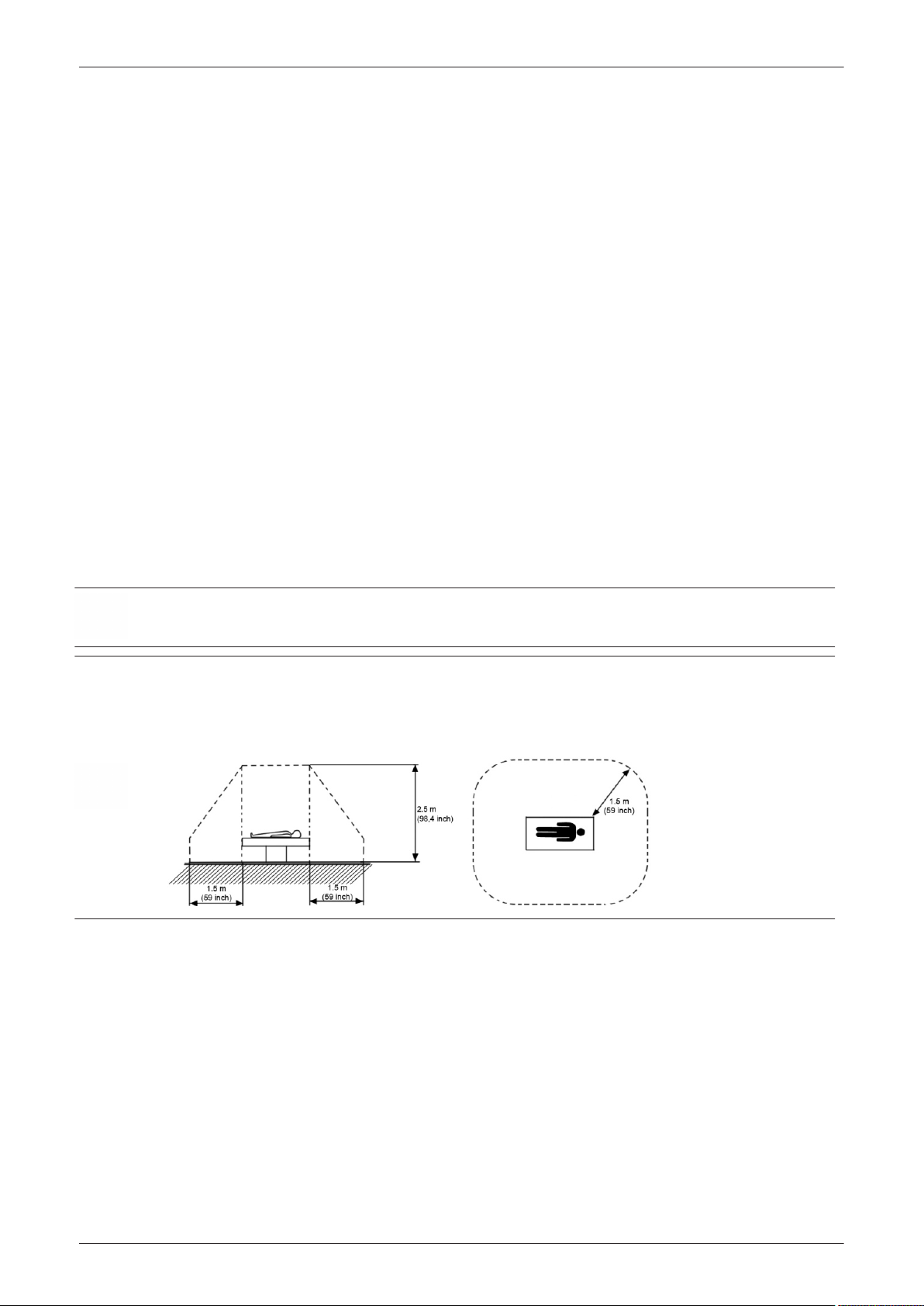
Setup Instructions
3.5 Connection of Auxiliary Devices
Content in this section
3.5.1 Connecting the LCD Monitor - - - - - - - - - - - - - - - - - - - - - - - - - - - - - - - - - - - - - - - 3-15
3.5.2 Connecting the OLED Monitor - - - - - - - - - - - - - - - - - - - - - - - - - - - - - - - - - - - - - - 3-16
3.5.3 Connecting the Black & White Printer - - - - - - - - - - - - - - - - - - - - - - - - - - - - - - - - 3-17
3.5.4 Connecting the 12 Volt DC Black & White Printer (EC350 only) - - - - - - - - - - - - - - 3-19
3.5.5 Connecting the Color Printer - - - - - - - - - - - - - - - - - - - - - - - - - - - - - - - - - - - - - - - 3-21
3.5.6 Connecting the Network Color Laser Printer - - - - - - - - - - - - - - - - - - - - - - - - - - - - 3-23
3.5.7 Connecting the DeskJet Color Printer - - - - - - - - - - - - - - - - - - - - - - - - - - - - - - - - 3-26
3.5.8 Connecting the Cellular Modem - - - - - - - - - - - - - - - - - - - - - - - - - - - - - - - - - - - - 3-28
3.5.9 Connecting the Wireless Network Adapter - - - - - - - - - - - - - - - - - - - - - - - - - - - - - 3-30
3.5.10 Connecting a Secondary "Patient" Monitor - - - - - - - - - - - - - - - - - - - - - - - - - - - - 3-31
3.5.11 Connecting the Foot Switch - - - - - - - - - - - - - - - - - - - - - - - - - - - - - - - - - - - - - - 3-33
3.5.12 Connecting the Barcode Scanner - - - - - - - - - - - - - - - - - - - - - - - - - - - - - - - - - - 3-34
3.5.13 Connecting the ECG-preamplifier - - - - - - - - - - - - - - - - - - - - - - - - - - - - - - - - - - 3-35
3.5.14 Connecting the USB Microphone - - - - - - - - - - - - - - - - - - - - - - - - - - - - - - - - - - - 3-36
3.5.15 Connecting an USB Flash Memory Stick - - - - - - - - - - - - - - - - - - - - - - - - - - - - - 3-37
3.5.16 Connecting an external USB Hard disk - - - - - - - - - - - - - - - - - - - - - - - - - - - - - - 3-37
3.5.17 General Remarks when using external USB-Devices - - - - - - - - - - - - - - - - - - - - 3-38
Note
Note
Always observe the instructions given in the manual of the peripheral/auxiliary device.
Warning
After each installation, the leakage currents have to be measured according to IEC 60601-1, IEC 62353 or
other relevant standard.
Caution
Please observe that some printers may not be medical devices! If Bluetooth-, Line- or Laser Printers are no
medical devices, they have to be located outside of the typical patient environment. Examples for typical
patient environments can be found in standard IEC 60601 (see illustrations below).
For more detailed Safety Considerations when connecting auxiliary devices to the Voluson E-Series system,
please review: Section 1.5.5 "Auxiliary Devices Safety" on page 1-23 .
3-14
Voluson E-Series Proprietary Service Manual
5539549APB Revision 8
Page 71

3.5.1 Connecting the LCD Monitor
Setup Instructions
Note
The LCD Monitor comes pre-installed with the system.
Voluson E-Series Proprietary Service Manual
5539549APB Revision 8
Figure 3-9 Connection Scheme - LCD Monitor
3-15
Page 72

Setup Instructions
3.5.2 Connecting the OLED Monitor
Note
The OLED Monitor is only available for Voluson E10 systems with SW EC320 (BT17) or higher. Usually it
comes pre-installed with the system.
3-16
Figure 3-10 Connection Scheme - OLED Monitor
Voluson E-Series Proprietary Service Manual
5539549APB Revision 8
Page 73

3.5.3 Connecting the Black & White Printer
Setup Instructions
Note
For more detailed description see Section 8.60 "Replacing optional Peripherals / How to mount Peripherals
at a later date" on page 8-202 .
1. Power Off/Shutdown the system as described in
2.
If your printer is UP-D898MD:
a. Connect your printer to any power source.
Note: If you connect the printer directly to an AC mains power outlet for auxiliary devices
(provided by the Voluson E-Series system), DO NOT yet connect the USB cable!
b.
Press the Power ON button (1) on the printer.
c. Enter the Menu by pushing the Joystick key (2).
d. Display "
e. Push the Joystick key to enter the sub menu.
f. Display "
g. Push the Joystick key to enter the sub menu.
h. Check/change display by shifting the Joystick key up or down:
*
*
i. Push the Joystick key again to confirm selection.
j. Proceed installation procedure as described below.
3. Connect the Black & White printer according to connection scheme, see:
4. When all cables are connected, press the Power ON button on the printer.
5. Power ON/Boot up the Voluson E-Series system as described in
All software drivers are pre-installed for the designated printer only.
6. After physical connection to the Voluson E-Series system, assign the printer to a remote key (P1, P2,
P3, P4, P5 and/or P6) as described in
7. Verify correct printer settings; see
Digital
Driver
"
DRV:897
"
DRV:898
" by shifting the Joystick key up or down.
" by shifting the Joystick key up or down..
" (at Windows 7 systems = EC300-EC320)
" (at Windows 10 systems = EC330 or higher)
2
Section 3.6.8 "Remote Control Selection" on page 3-60
Section 3.6.7 "Adjustment of Printer Settings" on page 3-57
Section 4.2.2 on page 4-4
Figure 3-11 on page 3-18
Section 3.4.1 on page 3-9
.
.
.
.
.
Note
Voluson E-Series Proprietary Service Manual
5539549APB Revision 8
The B&W printer should be connected to USB port C on the RTB Distribution Board Bottom.
Warning
After each installation, the leakage currents have to be measured according to IEC 60601-1, IEC 62353 or
other relevant standard.
2 The UP-D898MD features a legacy mode driver mode. In this mode the printer identifies itself as UP-D897 via the USB interface. Through this
feature the new medical printer UP-D898MD can be used to easily replace an existing UP-D897 unit in the field.
3-17
Page 74

Setup Instructions
3.5.3.1 Connection Scheme: AC B&W Printer
3-18
Figure 3-11 Connection Scheme - AC B&W Printer
Voluson E-Series Proprietary Service Manual
5539549APB Revision 8
Page 75

3.5.4 Connecting the 12 Volt DC Black & White Printer (EC350 only)
Setup Instructions
Note
Note
For more detailed description see Section 8.60 "Replacing optional Peripherals / How to mount Peripherals
at a later date" on page 8-202 .
1. Power Off/Shutdown the system as described in
2. Connect the 12 Volt DC Black & White printer according to connection scheme, see:
page 3-20
3. When all cables are connected, press the Power ON button on the printer.
4. Power ON/Boot up the Voluson E-Series system as described in
All software drivers are pre-installed for the designated printer only.
5. After physical connection to the Voluson E-Series system, assign the printer to a remote key (P1, P2,
P3, P4, P5 and/or P6) as described in
6. Verify correct printer settings; see
.
Section 3.6.8 "Remote Control Selection" on page 3-60
Section 3.6.7 "Adjustment of Printer Settings" on page 3-57
Section 4.2.2 on page 4-4
Section 3.4.1 on page 3-9
.
Section 3.5.4.1 on
.
.
.
The B&W printer should be connected to USB port C on the RTB Distribution Board Bottom.
Warning
After each installation, the leakage currents have to be measured according to IEC 60601-1, IEC 62353 or
other relevant standard.
Voluson E-Series Proprietary Service Manual
5539549APB Revision 8
3-19
Page 76

Setup Instructions
3.5.4.1 Connection Scheme: 12 Volt DC B&W Printer (EC350 only)
3-20
Figure 3-12 Connection Scheme - 12 Volt DC B&W Printer
Voluson E-Series Proprietary Service Manual
5539549APB Revision 8
Page 77

3.5.5 Connecting the Color Printer
Setup Instructions
Note
Note
For more detailed description see Section 8.60 "Replacing optional Peripherals / How to mount Peripherals
at a later date" on page 8-202 .
1. Power Off/Shutdown the system as described in
2. Connect the Color printer according to connection scheme, see:
3. When all cables are connected, press the Power ON button on the printer.
4. Power ON/Boot up the Voluson E-Series system as described in
All software drivers are pre-installed for the designated printer only.
5. After physical connection to the Voluson E-Series system, assign the printer to a remote key (P1, P2,
P3, P4, P5 and/or P6) as described in
6. Verify correct printer settings; see
Section 3.6.8 "Remote Control Selection" on page 3-60
Section 3.6.7 "Adjustment of Printer Settings" on page 3-57
Section 4.2.2 on page 4-4
Figure 3-13 on page 3-22
Section 3.4.1 on page 3-9
.
.
.
.
.
The Color printer should be connected to USB port D on the RTB Distribution Board Bottom.
Warning
After each installation, the leakage currents have to be measured according to IEC 60601-1, IEC 62353 or
other relevant standard.
Voluson E-Series Proprietary Service Manual
5539549APB Revision 8
3-21
Page 78

Setup Instructions
3.5.5.1 Connection Scheme: Color Printer
3-22
Figure 3-13 Connection Scheme - Color Printer
Voluson E-Series Proprietary Service Manual
5539549APB Revision 8
Page 79

3.5.6 Connecting the Network Color Laser Printer
Caution
Please observe that the complete Printer Assembly has to be located outside of the patient environment
(according to IEC 60601-1).
Caution
The printer being used may not be a medical device. The (Bluetooth) Printer Set and the Power Supply is
also not a medical device. The equipment meets the requirements of the EN 60950 Standard.
Setup Instructions
Note
It does not matter, whether an Ethernet crossover cable or a patch cable (straight through cable) is used.
The Network Color Laser Printer automatically reconfigures signals to yield expected results.
Connection directly to the Voluson E-Series
Physical connection:
Connect the Color Laser Printer.
1.
-
Connect the network cable to the Ethernet LAN connector on the Voluson E-Series system. The
other end connect to the Ethernet connector of the Color Laser Printer.
-
Connect the power cable of the printer to an external, non-isolated power source.
2. Install the Color Laser Printer as described in
Section 3.6.3 on page 3-40
.
Voluson E-Series Proprietary Service Manual
5539549APB Revision 8
Figure 3-14 Connection Scheme - Color Laser Printer (directly via network cable)
3-23
Page 80

Setup Instructions
Connection to work within the Network Environment
The Color Laser Printer can be connected to work within the network environment. Usually this will be the
hospital network.
Physical connection:
Two network cables are needed.
Connect the Color Laser Printer.
1.
-
-
-
2. Install the Color Laser Printer as described in
Connect the first network cable to the Ethernet LAN connector on the Voluson E-Series system.
The other end connect to a hospital network wall outlet.
Connect the second network cable to the Ethernet connector of the Color Laser Printer. The other
end connect to a hospital network wall outlet.
Connect the power cable of the printer to an external, non-isolated power source.
Section 3.6.3 on page 3-40
.
3-24
Figure 3-15 Connection Scheme - Color Laser Printer (within Network Environment)
Voluson E-Series Proprietary Service Manual
5539549APB Revision 8
Page 81

Connection for Wi-Fi Direct Communication
Setup Instructions
Note
Wi-Fi Direct Communication is only possible with printer type HP LaserJet M452nw, see Table 9-10.
Physical connection:
A WLAN network adapter is required.
1. Connect the power cable of the printer to an external, non-isolated power source.
2. Plug the proper WLAN adapter into an accessible USB port of the Voluson E-Series system.
3. Install the Color Laser Printer as described in
Section 3.6.3 on page 3-40
.
Figure 3-16 Connection Scheme - Color Laser Printer (Wi-Fi Direct Communication)
Voluson E-Series Proprietary Service Manual
5539549APB Revision 8
3-25
Page 82

Setup Instructions
3.5.7 Connecting the DeskJet Color Printer
Caution
Please observe that the complete Printer Assembly has to be located outside of the patient environment
(according to IEC 60601-1).
Caution
The printer being used may not be a medical device. The (Bluetooth) Printer Set and the Power Supply is
also not a medical device. The equipment meets the requirements of the EN 60950 Standard.
Connection via Bluetooth Adapter
The DeskJet Color Printer can be connected to an external, non-isolated power source. The Bluetooth
Adapter should be directly connected to any accessible USB port.
Note
Please use the proper Bluetooth Printer Connection set; see: Section 9.10.1 "Printers" on page 9-41 .
3-26
Figure 3-17 Connection Scheme - DeskJet Color Printer (via Bluetooth Adapter)
Voluson E-Series Proprietary Service Manual
5539549APB Revision 8
Page 83

Setup Instructions
Note
Note
HP Officejet 100 does not need an additional Bluetooth Printer Adapter (Bluetooth radio is integrated in the
printer). For installation instructions see Section 3.6.5 "Installing the DeskJet Color Printer via Bluetooth
connection" on page 3-49 .
Connection directly to the Voluson E-Series
The DeskJet Color Printer can be directly connected to any accessible USB port or the indicated USB port E
on the RTB Distribution Board Bottom via an USB cable.
If a DeskJet printer (e.g., HP Officejet 100) is connected directly via an USB-cable, use the AC mains power
outlet provided by the Voluson E-Series system (auxiliary output). This ensures medical grade separation
from AC mains.
Figure 3-18 Connection Scheme - DeskJet Color Printer (directly via USB cable)
Note
For installation instructions see Section 3.6.4 "Installing the DeskJet Color Printer directly via an USB-cable"
on page 3-49 .
Voluson E-Series Proprietary Service Manual
5539549APB Revision 8
3-27
Page 84

Setup Instructions
3.5.8 Connecting the Cellular Modem
Note
For more detailed description see Section 8.60 "Replacing optional Peripherals / How to mount Peripherals
at a later date" on page 8-202 .
1. Power Off/Shutdown the system as described in
2. Insert a Standard SIM card from your local provider.
a. Slide up the upper cover of the Cellular Modem Module to get access to the SIM card holder.
Figure 3-19 open the Cellular Modem cover
b. Insert the SIM card (see images below), fix it with the mounted clips and return the upper cover.
Section 4.2.2 on page 4-4
.
Note
Note
Figure 3-20 insert SIM card
SIM card requirements:
-
Data capable
-
Standard size
-
prepaid or post paid
Since the Voluson E-Series does not enable browser access, the service provider needs to enable the
Internet access on the SIM card before installation in the Cellular Modem. Please ensure from the service
provider, that there is no browser registration necessary when using the SIM card.
3. Connect the Cellular Modem according to connection scheme, see:
4. Power ON/Boot up the Voluson E-Series system as described in
5. After physical connection of the Cellular Modem to the Voluson E-Series system, perform Modem
Configuration as described in
6. Click the signal strength icon in the status bar and select
provider.
7. If it is desired to send E-mails, perform configuration as described in
8. If it is desired to use also MMS, adjust settings as described in
9. Assign the Modem to a remote key (P1, P2, P3, P4, P5 and/or P6) as described in
"Remote Control Selection" on page 3-60
10. Individually enter Patient's Email address and Phone number in the PID screen and adjust Email
and/or MMS options as described in
Section 3.13.3 "How to Setup the Cellular Modem" on page 3-87
Connect
and adjust the Email settings.
Section 3.13.6 on page 3-91
Figure 3-21 on page 3-29
Section 3.4.1 on page 3-9
for connection to the service
Section 3.13.4 on page 3-89
Section 3.13.5 on page 3-90
Section 3.6.8
.
.
.
.
.
.
The Cellular Modem should be connected to the USB port B on the RTB Distribution Board Bottom.
3-28
Warning
After each installation, the leakage currents have to be measured according to IEC 60601-1, IEC 62353 or
other relevant standard.
Voluson E-Series Proprietary Service Manual
5539549APB Revision 8
Page 85

3.5.8.1 Connection Scheme: Cellular Modem
Setup Instructions
Figure 3-21 Connection Scheme - Cellular Modem
Note
Voluson E-Series Proprietary Service Manual
5539549APB Revision 8
Connection is always the same (no differences between PC-Motherboard and/or BT-version of the system).
3-29
Page 86

Setup Instructions
3.5.9 Connecting the Wireless Network Adapter
Turn ON the power of the system and wait till the system has booted.
1.
2. Plug the Wireless Network adapter into an accessible USB port of the Voluson E-Series. All software
drivers are pre-installed for the designated Wireless Network adapter only.
The Wireless Network Adapter can be connected to any accessible USB port.
Note
Note
3-30
Figure 3-22 Connection Scheme - Wireless (USB) Network Adapter
Connection is always the same (no differences between PC-Motherboard and/or BT-version of the system).
After physical connection of the WLAN adapter to the Voluson E-Series system, follow the procedure
described in Section 3.13.2 "Wireless Network Configuration" on page 3-82 .
Voluson E-Series Proprietary Service Manual
5539549APB Revision 8
Page 87

3.5.10 Connecting a Secondary "Patient" Monitor
Caution
A Secondary "Patient" Monitor MUST NEVER be connected to the Voluson E-Series systems mains supply
directly! Always connect it to an appropriate Isolation Transformer (see
Caution
The secondary monitor is the only item to be connected to the isolation transformer.
Setup Instructions
Section 9.10.3 on page 9-46
).
Note
Note
Note
Note
A Secondary Monitor is NOT intended for diagnostic use. It is an additional device used to allow the patient
to watch the proceedings.
Take your time to think about the best position of the monitor in your facilities. Patients should be able to
view the monitor easily and without having to bend or turn around.
For more detailed description see Section 8.60 "Replacing optional Peripherals / How to mount Peripherals
at a later date" on page 8-202 .
1. Power Off/Shutdown the system as described in
2. Connect the Secondary Monitor according to connection scheme, see:
3. After physical connection to the Voluson E-Series system check, and if necessary change the Ext.
Monitor Output setting, see:
Section 3.7.1.8 on page 3-65
Section 4.2.2 on page 4-4
Figure 3-23 on page 3-32
.
.
.
Connection is always the same (no differences between PC-Motherboard and/or BT-version of the system).
Voluson E-Series Proprietary Service Manual
5539549APB Revision 8
3-31
Page 88

Setup Instructions
3.5.10.1 Connection Scheme: Secondary "Patient" Monitor
3-32
Figure 3-23 Connection Scheme - Secondary Monitor
Voluson E-Series Proprietary Service Manual
5539549APB Revision 8
Page 89

3.5.11 Connecting the Foot Switch
The Foot Switch should be directly connected to any accessible USB-port on the Voluson E-Series (e.g., on
rear of the system).
Setup Instructions
Note
Connection is always the same (no differences between PC-Motherboard and/or BT-version of the system).
After physical connection, adjust the Foot Switch as described in
Section 3.7.1.9 on page 3-65
.
Voluson E-Series Proprietary Service Manual
5539549APB Revision 8
Figure 3-24 Connection Scheme - Foot Switch
3-33
Page 90

Setup Instructions
3.5.12 Connecting the Barcode Scanner
The Barcode Scanner should be directly connected to any accessible USB-port on the Voluson E-Series
(e.g., next to DVD drive).
Note
Connection is always the same (no differences between PC-Motherboard and/or BT-version of the system).
3-34
Figure 3-25 Connection Scheme - Barcode Scanner
Voluson E-Series Proprietary Service Manual
5539549APB Revision 8
Page 91

3.5.13 Connecting the ECG-preamplifier
Setup Instructions
Note
Connection is always the same (no differences between PC-Motherboard and/or BT-version of the system).
Voluson E-Series Proprietary Service Manual
5539549APB Revision 8
Figure 3-26 Connection Scheme - ECG-preamplifier
3-35
Page 92

Setup Instructions
3.5.14 Connecting the USB Microphone
Note
Connection is always the same (no differences between PC-Motherboard and/or BT-version of the system).
1. Turn ON the power of the system and wait till the system has booted.
2. Plug the USB Micro Network adapter into an accessible USB port of the Voluson E-Series. Preferably
to one of the USB ports on the main monitor.
3-36
Figure 3-27 Connection Scheme - USB Microphone
Voluson E-Series Proprietary Service Manual
5539549APB Revision 8
Page 93

Operation
Press the DVD key on the control console to open the DVR/DVD menu.
Press the Touch Panel control to turn the Microphone
Rotate the Touch Panel control to adjust the recording volume of
the microphone (0-100%).
On / Off
Setup Instructions
.
During recording, the Touch Panel control toggles between
Unmute
.
3.5.15 Connecting an USB Flash Memory Stick
Note
Note
Note
Before connecting an USB device, please read Section 3.5.17 "General Remarks when using external USB-
Devices" on page 3-38 .
An USB Flash Memory Stick may be connected to an accessible USB port of the Voluson E-Series system
(e.g., on back of control console).
An external USB Flash Memory Stick can be connected once the system is powered ON, or after shutdown.
The Voluson E-Series, Windows detects the device and automatically installs a driver. During this process
several dialogs may pop up, starting with the „Found New Hardware” dialog.
Memory drives or sticks may be sensitive to EMC interference. This may affect system performance and/or
image quality.
Before disconnecting an external USB-device (e.g., USB Stick), the system must be informed about the
removal of the device! For this purpose press the Eject key on the keyboard.
For further details see Section 3.5.17.2 "External USB-Devices - Disconnection" on page 3-38 .
3.5.16 Connecting an external USB Hard disk
Note
Before connecting an USB device, please read Section 3.5.17 "General Remarks when using external USB-
Devices" on page 3-38 .
Mute /
An external HDD may be connected to an accessible USB port of the Voluson E-Series system (e.g., on
back of control console).
An external USB Hard Disk Drive can be connected once the system is powered ON, or after shutdown. The
Voluson E-Series, Windows detects the device and automatically installs a driver. During this process
several dialogs may pop up, starting with the „Found New Hardware” dialog.
Note
Memory drives or sticks may be sensitive to EMC interference. This may affect system performance and/or
image quality.
Note
Before disconnecting an external USB-device (e.g., USB Stick), the system must be informed about the
removal of the device! For this purpose press the Eject key on the keyboard.
For further details see Section 3.5.17.2 "External USB-Devices - Disconnection" on page 3-38 .
Voluson E-Series Proprietary Service Manual
5539549APB Revision 8
3-37
Page 94

Setup Instructions
3.5.17 General Remarks when using external USB-Devices
Caution
Do not connect or disconnect any external USB-devices to or from the system while scanning a patient! The
appearing dialogs could distract you from the scan!
3.5.17.1 External USB-Devices - Connection
When an external USB-storage device (such as an USB-memory stick or an external hard disk) is connected
to the Voluson E-Series, Windows detects the device and automatically installs a driver. During this process,
several dialogs may pop up, starting with the “Found New Hardware“ dialog.
The device is then accessible using the drive letter the system assigned to it.
Note
Note
If an external drive was not recognized automatically after connecting it, click Rescan Drive.
When connecting external USB devices, be sure to execute Safety Directions found in the Voluson E-Series
Basic User Manual resp. Instructions for Use.
3.5.17.2 External USB-Devices - Disconnection
Before an external USB-device (e.g., USB-memory stick) can be disconnected, the system has to be informed about the
removal of the device! For this purpose, press the Eject key on the keyboard.
Caution
Unplugging or ejecting USB devices without first stopping them can cause result in loss of valuable data.
By pressing the Eject
“Connect USB and Network Drives” window shows all USB and Network drives connected to the system.
Using this dialog, the USB-devices can be stopped before they are physically disconnected.
key on the keyboard, a dialog window (see:
Figure 3-28 below
) is displayed. The
3-38
Figure 3-28 Connect USB and Network Drives
To stop the external device, select it and then click the
Figure 3-29 Device can now be safely removed
Confirm the "‘Stop Device" dialog with OK and
Close
the "Connect USB and Network Drives" window.
Stop Device
button.
Voluson E-Series Proprietary Service Manual
5539549APB Revision 8
Page 95

3.6 Printer Installation
Setup Instructions
Note
Note
For connection schemes see Section 3.5 "Connection of Auxiliary Devices" on page 3-14 .
Content in this section
3.6.1 Installing the Digital Black & White Printer - - - - - - - - - - - - - - - - - - - - - - - - - - - - - 3-39
3.6.2 Installing the Digital Color Printer - - - - - - - - - - - - - - - - - - - - - - - - - - - - - - - - - - - - 3-39
3.6.3 Installing the Network Color Laser Printer - - - - - - - - - - - - - - - - - - - - - - - - - - - - - - 3-40
3.6.4 Installing the DeskJet Color Printer directly via an USB-cable - - - - - - - - - - - - - - - 3-49
3.6.5 Installing the DeskJet Color Printer via Bluetooth connection - - - - - - - - - - - - - - - - 3-49
3.6.6 Printer Installation manually - - - - - - - - - - - - - - - - - - - - - - - - - - - - - - - - - - - - - - - 3-56
3.6.7 Adjustment of Printer Settings - - - - - - - - - - - - - - - - - - - - - - - - - - - - - - - - - - - - - - 3-57
3.6.8 Remote Control Selection - - - - - - - - - - - - - - - - - - - - - - - - - - - - - - - - - - - - - - - - - 3-60
If a DeskJet printer (e.g., HP Officejet 100) is connected directly via an USB-cable, use the AC mains power
outlet provided by the Voluson E-Series system (auxiliary output). This ensures medical grade separation
from AC mains.
Warning
After each installation, the leakage currents have to be measured according to IEC 60601-1, IEC 62353 or
other relevant standard.
EC330 (BT18) and higher:
Whitelisting
If the
window might appear during the installation procedure.
option is available and activated in
System Setup - Administration
, a password login
3.6.1 Installing the Digital Black & White Printer
Power Off/Shutdown the system as described in
1.
2. Connect and install the printer as described in
3. Verify correct printer settings; see
4. Assign the printer to the remote keys P1, P2, P3, P4, P5 and/or P6; see
Selection" on page 3-60
.
Section 3.6.7 "Adjustment of Printer Settings" on page 3-57
3.6.2 Installing the Digital Color Printer
1. Power Off/Shutdown the system as described in
2. Connect and install the printer as described in
3. Verify correct printer settings; see
4. Assign the printer to the remote keys P1, P2, P3, P4, P5 and/or P6; see
Selection" on page 3-60
.
Section 3.6.7 "Adjustment of Printer Settings" on page 3-57
Section 4.2.2 on page 4-4
Section 3.5.3 on page 3-17
Section 3.6.8 "Remote Control
Section 4.2.2 on page 4-4
Section 3.5.5 on page 3-21
Section 3.6.8 "Remote Control
.
.
.
.
.
.
Voluson E-Series Proprietary Service Manual
5539549APB Revision 8
3-39
Page 96

Setup Instructions
3.6.3 Installing the Network Color Laser Printer
The Network Color Laser Printer can either be connected
directly to the Voluson Expert Series system,
•
to work within the network environment (usually the hospital network),
•
via Wi-Fi Direct (communication without requiring a wireless access point),
•
Note
3.6.3.1 Prepare the Network Color Laser Printer
Wi-Fi Direct Communication is only possible with printer type HP LaserJet M452nw. For connection scheme
refer to Section 3.5.6 on page 3-23 .
Figure 3-14 on page 3-23
Figure 3-15 on page 3-24
Figure 3-16 on page 3-25
1. Power Off/Shutdown the system as described in
2. Connect the printer as described in
3. Power On/Boot Up the system as described in
4. Press the Power ON button on the printer.
5. Install ink tanks and load paper.
6. Wait until the printer displays
Section 3.5.6 on page 3-23
Ready
.
Figure 3-30 printer controls
Section 4.2.2 on page 4-4
.
Section 4.2.1 on page 4-3
.
.
1 Power ON 5 Right >
2 Display 6 OK
3 Status Indicators 7 Left <
4 Cancel 8 Back
3.6.3.2 Network Setup
Note
Network Setup of the Printer depends on the used printer and the connection type!
Content in this section
3.6.3.2.1 Network Setup when the printer is connected by means of Network cable(s) - - 3-41
3.6.3.2.2 Network Setup when the printer is connected via Wi-Fi Direct - - - - - - - - - - - - - 3-42
3-40
Voluson E-Series Proprietary Service Manual
5539549APB Revision 8
Page 97

3.6.3.2.1 Network Setup when the printer is connected by means of Network cable(s)
Setup Instructions
By means of the Printer Controls Left < , Right > and OK set the IP4v Config Method to
1.
asterisk is displayed on the right side of the display.
Figure 3-31 IP4v Config Method - Auto IP
2. By means of the Printer Controls Left <
Figure 3-32 Reports -> Configuration Report
, Right > and OK print out the
3. Press the Back button until the Printer displays
Ready
again.
Configuration Report
Auto IP
.
. An
4. In the
Product Settings
169.254.81.224
Note
Keep in mind this unique printer IP Address (IPv4 Address). It must be entered during Printer Installation
procedure.
Proceed with
Voluson E-Series Proprietary Service Manual
5539549APB Revision 8
Section 3.6.3.4 "Network Color Laser Printer Installation Procedure" on page 3-44
Figure 3-33 Configuration Report -> IPv4 Address
section you can find the printers IP Address (e.g., IPv4 Address:
).
.
3-41
Page 98

Setup Instructions
3.6.3.2.2 Network Setup when the printer is connected via Wi-Fi Direct
By means of the Printer Controls Left < , Right > and OK set the Wi-Fi Direct to
1.
displayed on the right side of the display.
Figure 3-34 Wi-Fi Direct - On
2. By means of the Printer Controls Left < , Right > and OK print out the
Figure 3-35 Reports -> Network Summary
Ready
3. Press the Back button until the Printer displays
again.
On
. An asterisk is
Network Summary
.
Note
3-42
Figure 3-36 Network Summary -> IP Address and Wi-Fi Direct Password
4. In the
Wi-Fi Direct Setup
and the
Wi-Fi Direct Password
For example: IP Address 192.168.223.1
section on the first page of the printout you can find the printers
.
Wi-Fi-Password 78407625
IP Address
Keep in mind this unique printer IP Address (IPv4 Address). It might be entered during Printer Installation
procedure. The Wi-Fi Direct Password must be entered when connecting to the Wi-Fi network. For security
purposes, this "Password" needs to be kept a secret!
Voluson E-Series Proprietary Service Manual
5539549APB Revision 8
Page 99

3.6.3.3 Configure Wi-Fi Network on the Voluson E-Series system
Press the Utilities key on the control console.
1.
2. In the “Utilities” menu touch the
3. On the right side of the screen select
4. Click the
5. In the displayed window select the printers wireless network (
WLAN Configuration
Setup
button.
button to invoke the setup desktop on the screen.
Connectivity
and then click the
Device Setup
Direct-15....
Setup Instructions
tab.
), then click
Connect
.
Note
If the printers wireless network is not listed, verify WLAN adapter connection. If still not listed, probably the
(A6210) WLAN driver is not installed on the Voluson E-Series system by default. For troubleshooting
purposes, proceed with Section 3.6.3.3.1 on page 3-44 .
6. Enter the previously print out Wi-Fi Direct Password (e.g., 78407625, see
confirm the key and then click
Figure 3-37 Wi-Fi Direct Wireless Network Configuration
Connect
.
Figure 3-36 on page 3-42
),
7. When the printers wireless network (Direct-15 ...) is connected, click on
Proceed with
Close
.
Section 3.6.3.4 "Network Color Laser Printer Installation Procedure" on page 3-44
.
Voluson E-Series Proprietary Service Manual
5539549APB Revision 8
3-43
Page 100

Setup Instructions
3.6.3.3.1 The Wi-Fi Direct Printer is not listed - Troubleshooting
If you have a “standard GE” service dongle, check if the WLAN adapter A6210 is already identified by the
Voluson E-Series system.
Connect the service dongle to any accessible USB port and enter the GE revolving password.
•
Press the CRTL + ESC
•
Select
•
All Programs
Procedure
1. Download the appropriate printer driver from GE Box
https://ge.box.com/s/w2fespm5iqg6qbiqfyhrftw77sdyqetb and extract files to USB stick or CD.
Press the Utilities key on the control console.
2.
3. In the “Utilities” menu touch the
4. On the right side of the screen select
5. Enter the password « she » and click the
6. In the Service Tools page click the
a. In the displayed window choose the media (e.g., External USB Drives E:.
b. Click on
c. Select the folder with the WLAN driver (e.g., A6210_driver) and then click OK.
d. Now click
Change folder
Load
keys to open the Windows Start menu.
-
Devices and Printers
Setup
and check the displayed screen for unspecified devices.
button to invoke the setup desktop on the screen.
Administration
Accept
button.
ASI
button.
and browse for the proper folder.
.
and then click the
Service
tab.
Figure 3-38 Load WLAN driver
7. In the next window select the proper file and click
8. Check mark the License Agreement screen with
9. When the driver is successfully installed, click OK.
Proceed with
Section 3.6.3.3 "Configure Wi-Fi Network on the Voluson E-Series system" on page 3-43
I agree
3.6.3.4 Network Color Laser Printer Installation Procedure
1. Download the appropriate printer driver from GE Box
http://ge.box.com/s/sgm4qbecnj9e38fbv8lywnadj3hg20hs and extract files to USB stick or CD.
Connect the USB stick to the Voluson E-Series system or insert the CD into the drive.
2.
3. Press the Utilities key on the control console.
4. In the “Utilities” menu touch the
5. On the right side of the screen select
6. Click the
Please read the displayed message carefully and click
Add Printer
button.
Setup
button to invoke the setup desktop on the screen.
Connectivity
OK
to start installation.
and then click
and then click the
Yes
if you have skills to do this.
Next
.
Peripherals
.
tab.
3-44
Voluson E-Series Proprietary Service Manual
5539549APB Revision 8
 Loading...