

GE AS0CD09, AS0CD12, AS1CD09, AS1CD12, AS0CD18 Owner's Manual & Installation Instructions
...Page 1
GEAppliances
Cooling Only Models
HeutPun@ Modds
ASOCD09 AS1CD09
ASOm09 AS1RD09
ASOCD12 AS1CD12
ASORD12 AS1RD12
ASOCD18 AS1CD18
ASORD18 AS1RD18
Pub. No. 4$-7373-1 CG2-98
Page 2
Safety lnfimnation
SafiXyPrecautions . . . . . . . . . . ...3
Congratulations!
YouAre Now Pati of the GEFamily
Welcome to the GE family. We’re proud of our quality products and we are committed
to providing dependable service. You’ll see it in this easy-to-use Owner’s Manual and
you’ll hear it in the friendly voices of our customer service department.
Best of all, you’ll experience these values each time you use your air conditioner.
That’s important, because your new air conditioner will be part of your fkrnily for
many years. And we hope you will be part of ours for a long time to come.
We thank you for buying GE. We appreciate your purchase, and hope you will
continue to rely on us whenever you need quality appliances for your home.
OperatingInstmctions
Remote Control
h5atures . . . . . . . . . . . . . . . . ...4-+
Operation Mode Selection . . . . .Z 8
Additions\ Features . . . . . . ...9-11
Careand C/caning . . . . . . . . . . ..l2
MWation Instructions
Electrical Requirements . . . . . . . .13
Location . . . . . . . . . . . . . . . . . . ..l4
Indoor Unit Installation . . ...1516
Connection of Pipes . . . . . . . .17–22
Check Connection . . . . . . ...23-26
TestRun . . . . . . . . . . . . . . . . . ...27
Installation Templates . . . ...2829
lFoub/eshooting71ps
Before You
CallForService . . . . . . . . . . . ...30
Normal Operating Sounds . . . ...30
CustomerSeNice
Warranty . . . . . . . . . . . . . . . . . ..3l
Service Telephone
Numbers . . . . . . . . . . . .Back Cover
2
GE& You,A Service Partnemhip.
d
FOR YOUR RECORDS
Write the model and serial numbets hem for the indoor and
outdoor units:
Indoor model #
Serial #
Outdoor model #
Serial #
You can fmd them on a label on the side of each unit,
Staple sales slip or cancelled check here.
Proof of the original purchase date is needed to obtain service
under the
~ty.
6
.
READ THIS MANUAL
Inside you will find many helpful hints on how to use and maintain
your air conditioner properly.Just a little preventive care on your
part can save you a great deal of time and money over the life of
your air conditioner.
You’ll fmd many answers to common problems in the Before YoU
Ca// For Service section. Ifyou review our chart of Troubleshooting
~ps first, you may not need to call for service at all.
)Ll I VI(JC
i!i!i!i
IFYOU Nf..ll SED~ IIfi~
~.:
/
cd away. A listof toll-free customer sefice num~ers is ~cl;ded in
~ If You do need sem-ice, You can relax knowing help is only a phone
the back section. Or, you can always call the GE Answer Center@ at
800.626.2000,24 hours a day, 7 days a week.
For anyservicewhichrequiresentryinto the
refi-igerantsealedsystem,Federalregulations
requiretheworkbe performed byatechnician
havinga ClassII or Universalcertification.
Page 3
IMPORTANTSAFETYINFORMATION.
READALLINSTRUCTIONSBEFOREUSING.
A WARNING!
For your safe~ the informationin this manual must be followed to minimize the risk of fire, electric shock
or personal injury
SAF~PRECAUTi’ONS
● ?%This system must be properly installed in
NOTES:
, . ,%
accordance with the Installation Instructions
1’:~We strongly recommend that any servicing
before it is used.
be pefiormed by a qualifled individual.
.?.:
Be certain the power source is disconnected “
.-
before servicing the product.
$~ Since outdoor condensing unit has a sump
heater on the compressor for heat
pump
models, the power’should be turkd on’at
For anyservicewhichrequiresentq
least 5 hours before unit opemhon. Leave
into the
refrigerantsealedsystem,
the
power on unless you will not be using the
Federalregulationsrequirethework
system for an extended period of time.
II
be performed by a technicianhavinga
ClassII orUniversalcertification.
II
3
Page 4
About the remote control on the svstem.
The remote control transmits the signals to the system.
4
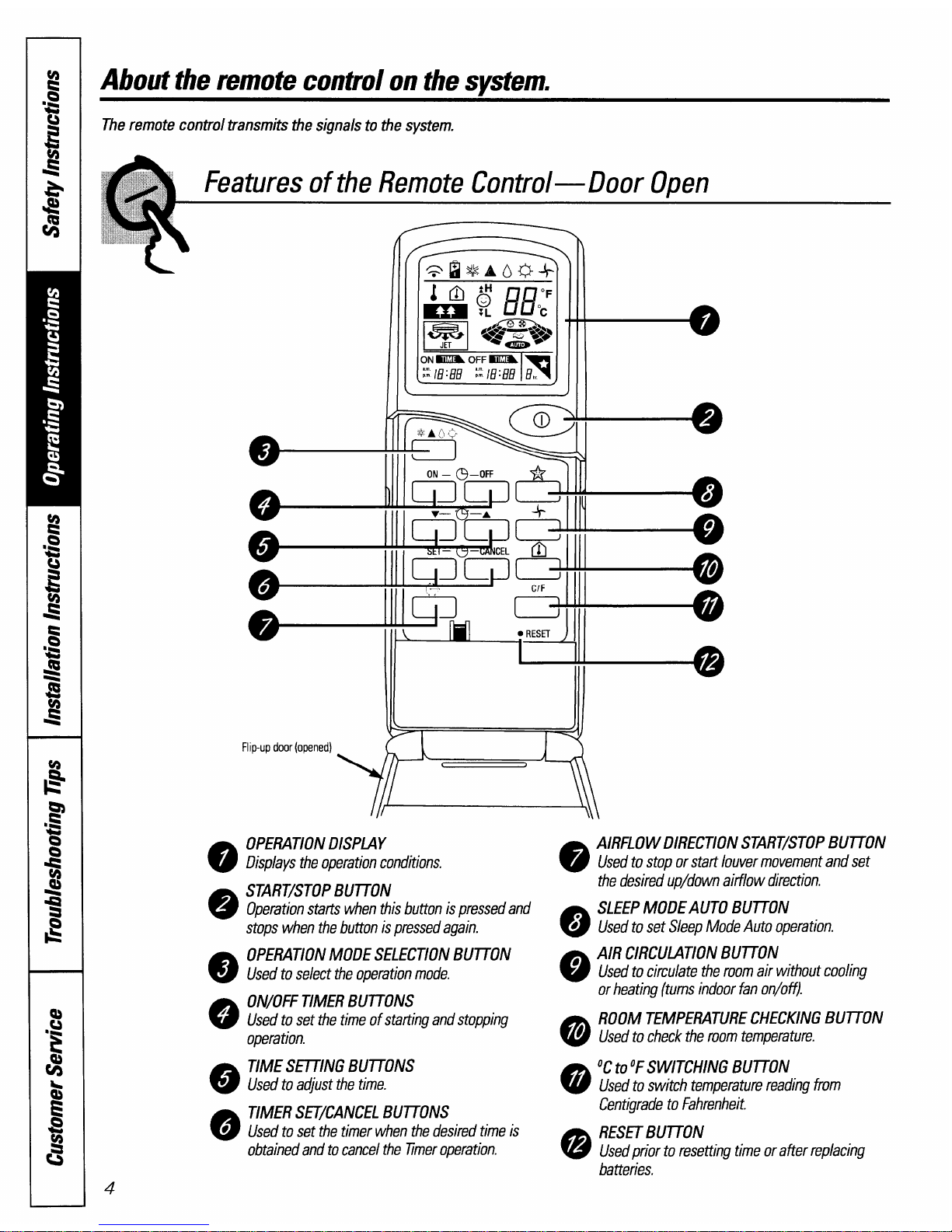
Features of the Remote Control—Door Open
.
II
1--o
—
1111
ON – @–OFF
——
I
/
Flip-up door (opened)
\ Ifl
Y==3
OPERATION DISPLAY
Displays the operation conditions.
START/STOP BIJITON
Operation starts when this button is pressed and
stops when the button is pressed again.
OPERATION MODE SELECTION BUTTON
Used to select the operation mode.
ON/OFF TIMER BUTTONS
Used to set the time of statting and stopping
operation.
TIME SETTING BUITONS
Used to acjust the time.
TIMER SEVCANCEL
BUTTONS
Used to set the timer when the desired time is
obtained and to cancel the fimer operation.
AIRFLOW DIRECTION START/STOP BU~ON
Used to stop or start louver movement and set
the desired up/down aitilow direction.
SLEEP MODEAUTO BU~ON
Used to set Sleep Mode Auto operation.
AIR CIRCULATION BUTTON
Used to circulate the room air without cooling
or heating (turns indoor fan on/off).
ROOM TEMPERATURECHECKINGBUTTON
Used to check the room temperature.
‘C to “SWITCHING BUTTON
Used to switch temperature reading from
Centigrade to Fahrenheit.
RESET BUTTON
Used prior to resetting time or after replacing
batteries.
Page 5
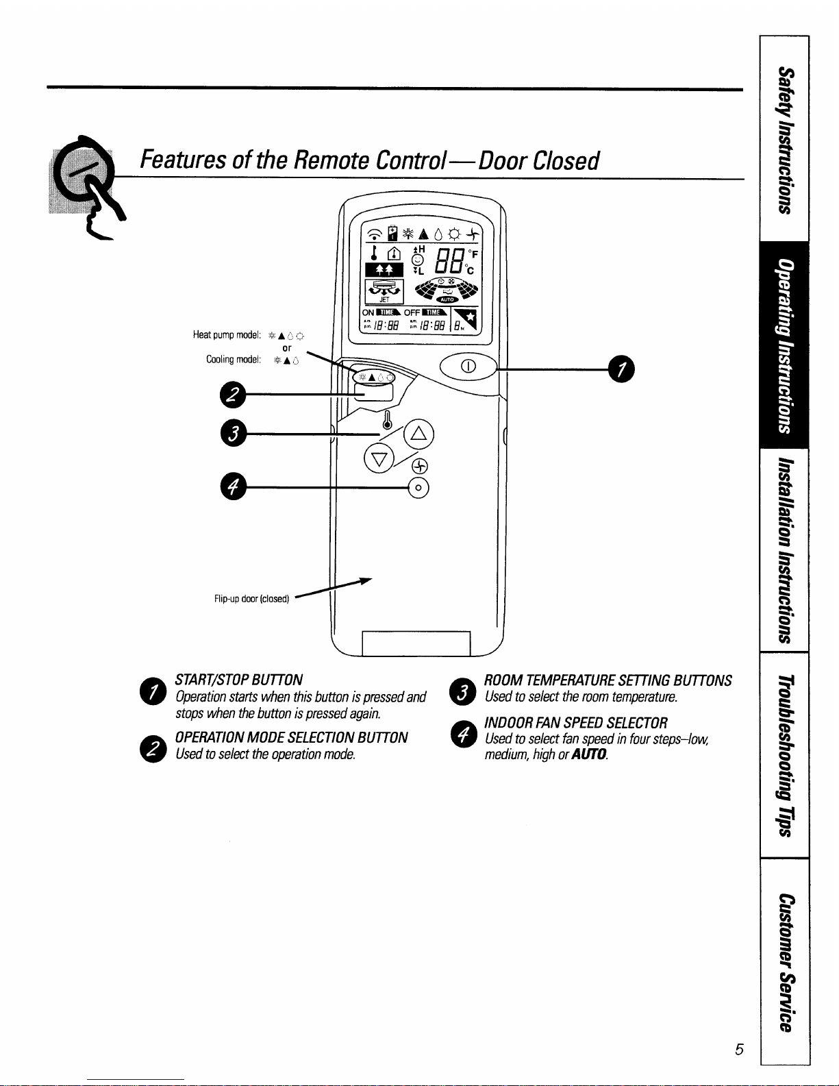
Flip-up door (closed) =
START/STOPBUTTON
Operation starts when this button is pressed and
Q
stoos when the button is Dressed aaain.
r
OPERATIONMODE SELECT10N;U710N
o
L
Used to select the operation mode.
ROOM TEMPERATURESETTING BUTTONS
Used to select the room temperature.
INDOOR FAN SPEEDSELECTOR
Used to select fan speed in four steps–low
medium, high orAl)TO.
5
Page 6
About the remote control on the system.
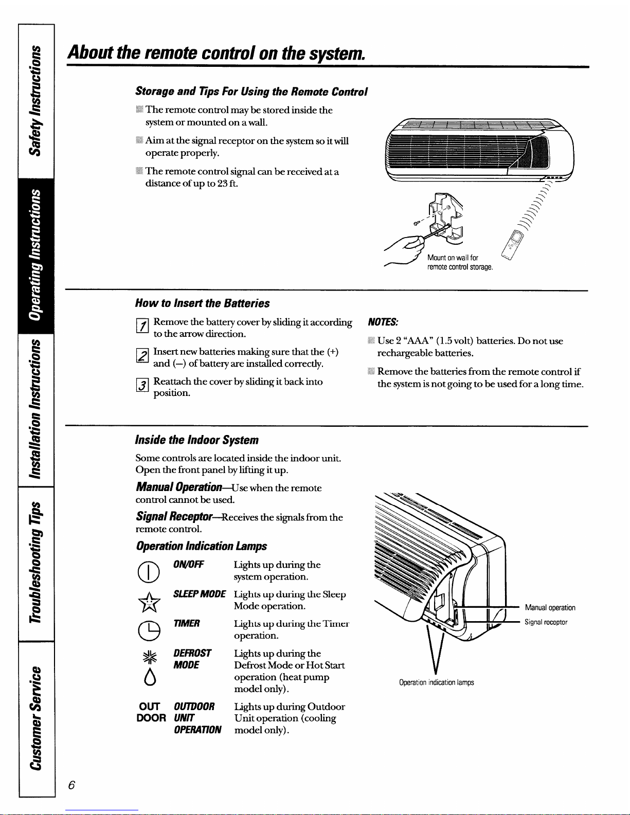
Storage and fips For Using the Remote Control
1~
The remote control maybe stored inside the
system or mounted on awall.
: Aim at the signal receptor on the system so itwill
operate properly.
:’ The remote control signal can be received at a
distance of up to 23 ft.
&
y+
@’
Mount on wall for
w
remote control storage.
How to Insert the Batteries
❑
Remove the batteq cover by sliding it according
N07ES:
to the arrow direction.
~~Use 2 “M” (1.5 volt) batteries. Do not use
❑
Insert new batteries making sure that the (+)
rechargeable batteries.
and (—) of battery are installed correctly.
~~~Remove the batteries from the remote control if
❑
Reattach the cover by sliding it back into
the system is not going to be used for a long time.
position.
Inside the Indoor System
Some controls are located inside the indoor unit.
Open the front panel by lifting it up.
~fVlf/a/ @t?rafiOn+se when the remote
control cannot be used.
Signs/ ReceptOr+eceives thesignalsfrom the
remote control.
Operation Indication Lamps
(D
Onyow
*
SLEEPMODE
. .
a
77/UER
j~
DEFROST
o
MODE
OUT 0U7DOOR
DOOR UNIT
OPERAllON
Lights up during the
system operation.
fights up during the Sleep
Mode operation.
Lights up during the Timer
operation.
Lights up during the
Defrost Mode or Hot Start
operation (heat pump
model only).
Lights up during Outdoor
Unit opemtion (cooling
model only).
6
— Manual operation
— Signal receptor
Operation indication lamps
Page 7
How to use the Operation Mode Selection button.
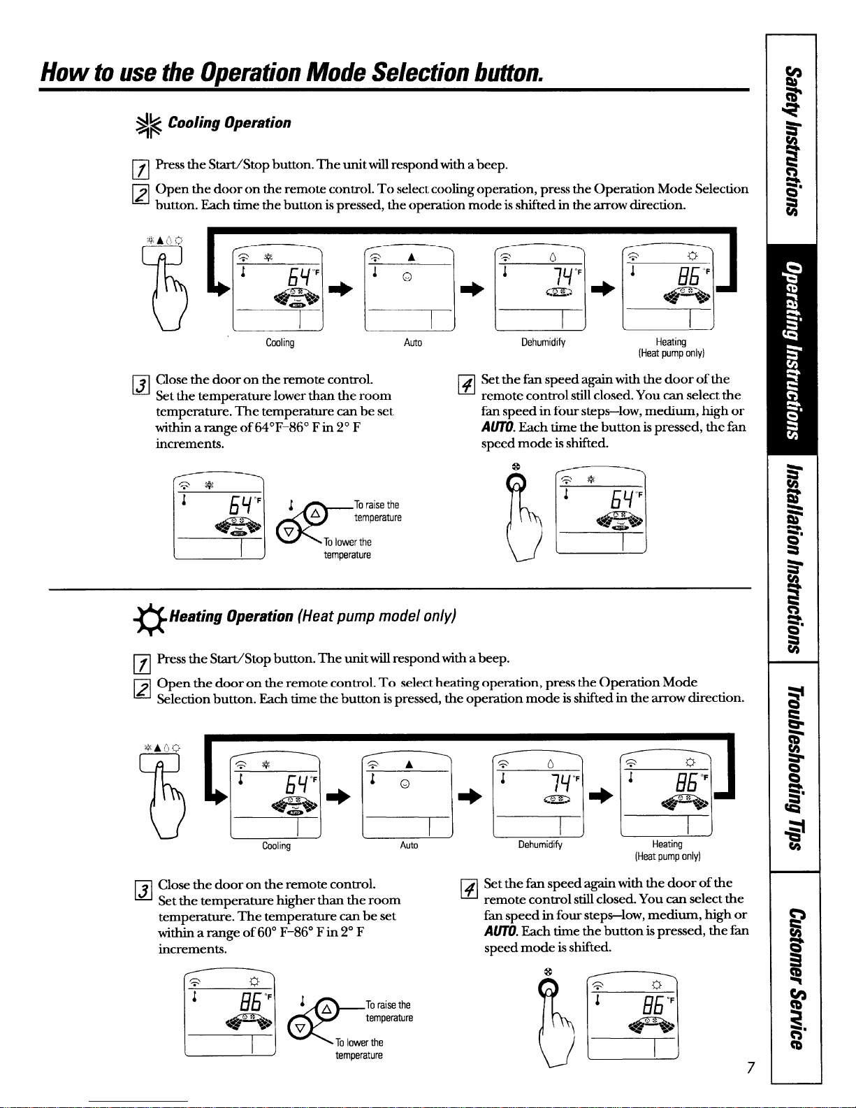
~~ Cooling Operation
❑
Press the Start/Stop button. The unit will respond with abeep.
❑Opentiedoorontieremotecon~ol.Toselectcooltigopemtion,presstieOpemtionModeSelection
button. Each time the button ispressed, the operation mode is shifted in the arrow direction.
13J
Cooling
Auto
Close the door on the remote control.
Set the tem~erature lower than the room
❑
temperatu& The temperature can be set
within am.nge of64°F–860 Fin 2° F
increments.
l’==-)
J
H
“F
4A
e (4?
To raise the
Q“
temperature
*5
v
-----5-
To lower the
L
I
)
temperature
l~J r_17
Dehumidify
Heating
(Heat pump only)
Set the fan speed again with the door of the
remote control still closed. You can select the
fan speed in four steps-low, medium, high or
AlKU. Each time the button is pressed, the fa
speed mode is shifted.
Km
Q *<
J
bY
“F
%@%J&>
a
Heating Operation (Heat pump model only)
pJ
Press the Start/Stop button. The unit will respond with a beep.
❑Openthedoorontheremotecontrol.To selectheatingoperation, presstheOpemtionMode
Selection button. Each time the button is pressed, the operation mode is shifted in the arrow direction.
Cooling
Auto
Close the door on the remote control.
Set the temperature higher than the room
❑
tempemture. The temperature can be set
witl& a range of 60° F:86” Fin 2° F
increments.
LA
&
To raise the
temperature
v
Tolower the
temperature
[~J l~J
Dehumidify
Heating
(Heat pump only)
Set the fim speed again with the door of the
remote control still closed. You can select the
fan speed in four steps-low, medium, high or
A(m). Each time the button is pressed, the fian
speed mode is shifted.
Page 8
How to use the OperationMode Selection button.
A
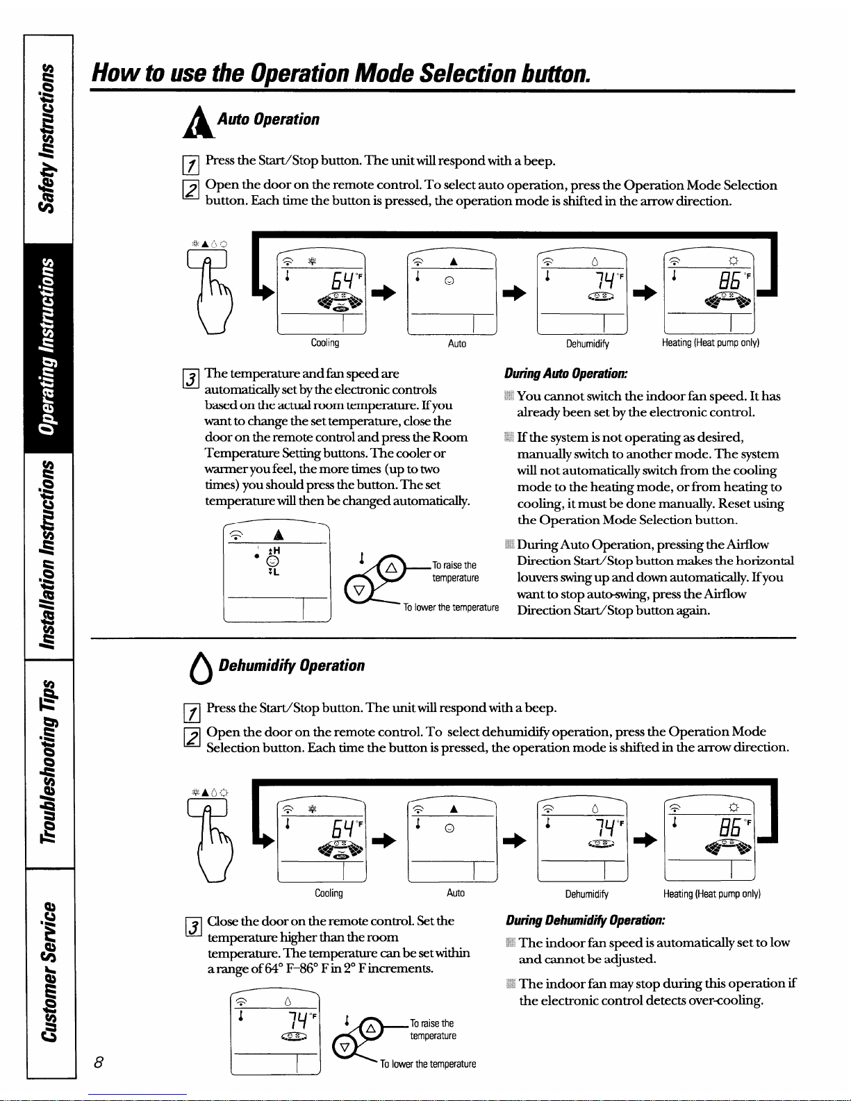
Auto Operation
El
Press the Start/Stop button. The unit will respond with a beep.
~ Open the door on the remote control. To select auto opemtion, press the Operation Mode Selection
Each time the button is pressed, the operation ‘mode is s&fted in th; arrow direction.
“E!!wM3E!!3
Cooling
Auto
Dehumidify
Heating (Heat pump only)
H
The temperature and fan speed are
automatically setby the electronic controls
based on the actual room tempemture. lfyou
want to change the settempemture, close the
door on the remote control and press the Room
Tempemture Settingbuttons. The cooler or
warmer you feel, the more times (up to two
times) you should press the button. The set
tempemture will then be changed automatically.
l)uring Auto Operation:
.’ You cannot switch the indoor fim speed. Ithas
already been set by the electronic control.
. If the system is not operating as desired,
manually switch to another mode. The system
will not automatically switch from the cooling
mode to the heating mode, or from heating to
cooling, itmust be done manually. Reset using
the Operation Mode Selection button.
L__l
Q
A
‘ During Auto Operation, pressing the Airflow
“g
1A
@
Toraise the
Direction Start/Stop button makes the horizontal
temperature
louvers swing up and down automatically. Ifyou
---r V
want to stop auto-swin
To lower the temperature
%
press the Airflow
Direction Start/Stop button again.
8
()
Dehumidi@ Operation
pJ
Press the Start./Stop button. The unit will respond with a beep.
❑Openthedoorontheremotecontrol.To selectdehumi@operation, presstheOperationMode
Selection button. Each time the button ispressed, the operation mode is shifted in the arrow direction.
(==--)
\/l—
[
I
)
[
I
)
(
I
J
Cooling
Auto
Dehumidify
Heating (Heat pump only)
1
J
Close the door on the remote control. Setthe
During l)ehumid~ Operation:
tempemture higher than the room
‘~~The indoor fim speed isautomatically set to low
tempemture. The temperature can be setwithin
and cannot be adjusted.
am.nge of 64° F–86° Fin 2° Fincrements.
I
‘ The indoor fim may stop during this opemtion if
the electronic control detects over=cooling.
J*
&
Tocaisethe
temperature
v
To lower the temperature
Page 9
Additional features.
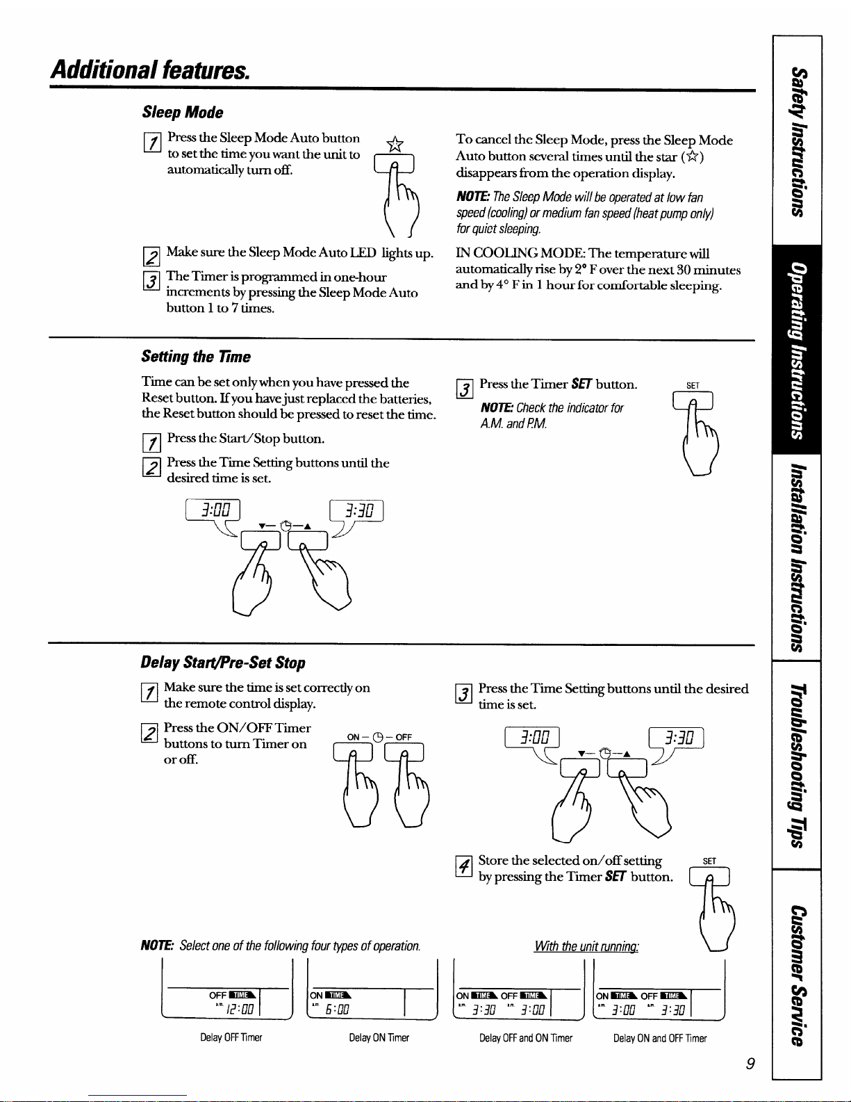
S/eep Mode
Press the Sleep Mode Auto button ..
to set the time you want the unit to
*
automatically turn off.
m
Make sure the Sleep Mode Auto I.XD lights up.
The Timer isprogrammed in one-hour
increments by pressing the Sleep Mode Auto
button 1 to 7’times.
To cancel the Sleep Mode, press the Sleep Mode
Auto button several times until the star (*)
disappean from the opemtion display.
N07E: TheSleep Mode will be operated at low fan
speed (cooling) or medium fan speed (heat pump only)
for quiet sleeping.
IN COOIJNG MODE: The temperature will
automatically rise by 2° Fover the next 30 minutes
and by 4° Fin 1 hour for comfortable sleeping.
Setting the llme
Time can be set only when you have pressed the
❑
Press the Timer SETbutton.
Reset button. Ifyou havejust replaced the batteries,
the Reset button should be pressed to reset the time.
NU7E:Check the indicator for
A.M. and PM.
pJ
Press the Start./Stop button.
❑
Press the Time Setting buttons until the
desired time is set.
SET
75
Delay Star@re-Set Stop
Make sure the time is set correctly on
the remote control display.
Press the ON/OFF Timer
buttons to turn Timer on
or off.
mom
(x!?
N07E: Select one of the following four ~pes of operation.
k
Delay OFFTmer
b
Delay ON Tmer
❑
Press the Time Setting buttons until the desired
time is set.
~ Store the selected on/offsetting
u by pressing the Timer SET butt&.
With the unit runnina.”
SET
75
Delay OFFand ONTmer
k
Delay ONand OFFTimer
9
Page 10
Additional features.
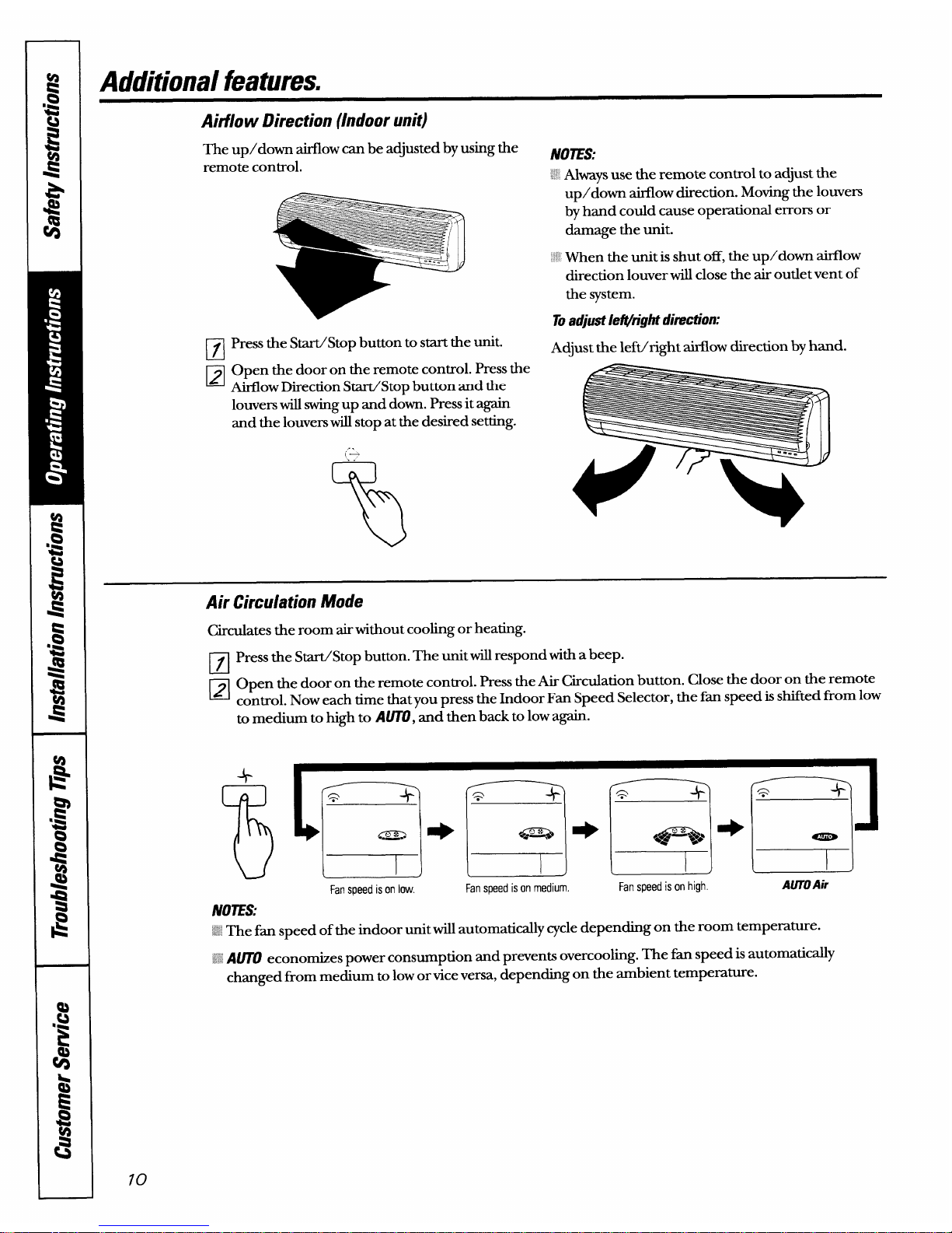
Aitilow Direction (Indoor unit)
The up/down airflow can be adjusted by using the
NOIES:
remote control.
“ Always use the remote control to adjust the
El
PJ
Press the Start/Stop button to start the unit.
Open the door on the remote control. Press the
Airflow Direction Start/Stop button and the
louvers will swing up and down. Press it again
and the louvers will stop at the desired setting.
..
(-
.,
%
up/down airflow direction. Moving the louvers
by hand could cause operational errors or
darnage the unit.
~When the unit is shut off, the up/down airflow
direction louver will close the air outlet vent of
the system.
Toadjust leiWight direction:
Adjust the leftiright airflow direction by hand.
Air Circulation Mode
Circulates the room airwithout cooling or heating.
m
Press the Start/Stop button. The unit will respond with a beep.
~ Opentiedoorontieremotecon&ol.ResstiefiChcdationbutton.Clowtiedoorontieremote
control. Now each time that you press the Indoor Fan Speed Selector, the fan speed is shifted from low
to medium to high to lWTO, and then back to low again.
fj f--f-q+ ~.
Fanspeed is on low.
Fanspeed is on medium.
N07ES:
‘~<’
The fan speed of the indoor unit will automatically cycle depending on the room temperature.
-+
Fanspeed is on high.
AUTOAir
;; AUTO economizes power consumption and prevents overcooking. The fin speed is automatically
changed from medium to low or vice versa, depending on the ambient temperature.
Page 11

Manual Operation
If the remote control will not operate the unit, open the front panel upward and press the Manual
Operation button.
Use a pencil to press
the button.
Ifyou want to stop operation, raise the front panel and press the Manual Operation button again.
During Manual Operation, the opemting conditions are automatically set asfollows:
holing Only
Heat Pump Model
Model
Room Temp. Room Temp.
Room Temp.
above X“ F ZYFttm/ 76°F
below 7V0F
Operating Mode
I
Cooling
I
Cooling
I
Dehumidify
I
Heating
I
Indoor Fan Speed
I
High
I
High
I Fan turns on/oti automatically I High
I
Setting Temperature
I
72° F
I
72” F
I
Air intake temperature
I
76° F
I
77
Page 12

Careand cleaning of the air conditione~
CAIMON: Before performing any maintenance, turn off the main power to the system.
Indoor Unit
Grille, Caseand Remote Control
Air Filters
Turn the system off before cleaning. To clean, wipe
The two air faltersbehind the front grille should be
with a soft, dry cloth. Do not use bleach or abrasives. checked and cleaned at least eve~ 30 days or more
Air intake vent
~ ‘ ‘ ‘ ‘ ‘ ““’‘““-‘“
Air outlet vent Horizontal louver Vertical louver Airfilters
often if necess~.
Lift the fi-ont access panel and pull the filter tab
slightly forward to remove the filter. Clean the filter
with a vacuum or warm, soapy water. Rinse and let
the falterdry before replacing it.
GAWUIN: DO
NOToperate the systemwithout a fifter
becausedirtandlint will clog it andreducepetiormance.
Outdoor Unit
The heat exchanger coils and panel vents of the
outdoor unit should be checked regularly. If
clogged with dirt or debris, the heat exchanger and
panel vents may be professionally steam cleaned, a
service available through your GE service outlet.
+ Supply power must be disconnected before cleaning the
outdoor unit.
‘:’ Dirty or clogged coils will reduce the operating efficiency of
.,..
the system and cause higher operating costs.
Air intake vent
Air outlet vent
If you’re closing up for the season.. .(cooling-only models)
❑
Operate the system in the Air Circulation mode
for 2 hours. This will dry out the system.
❑
Remove the batteries horn the remote control.
❑
Cover the outdoor unit with a protective cover.
72
Page 13

Installation ilKtrUCtiOllSm
Parts included
!
Outdoor unit
Type A screws
Type B ~ ‘
‘;;:-J; ‘Cref.jr’ro’
b:. L----J fi@--== ; [
(PD-l-+-J @--
Installation plate
G9@’”
Indoor unit
N07E: Optional tube kits—which
contain pre-flared insulated tubing,
wiring, etc., to complete system
installation requirements—are
available from General Electric.
\M/
\n
READ THEINSTALLA770N INSR?UCRONS CAREFUUYAND COMPLETELYBEFORE YOU BEGIN.
IMPORZANTN07ES:
Follow National Electiic Codes (NEC) andjor local codes and ordinances.
For personal safe~ this system must be properly grounded.
Protective devices (fuses or circuit breakers) acceptable for installation are specified on the
nameplate of each unit
Servicing and installation of the refrigerant system must be petiormed only by a licensed, tiVAC
cetified technician.
Make sure to avoid wiring or plumbing inside the wall when installing.
II 1
hr any sem-ce which requin?sentry into the refrigerant sealed system, hderal regulations mquim tie
work be performed by a technician having a Class II or Univemal certification.
. \\ I
●// CAUTION
Electrical Requirements
Be certain all wiring complies with local building codes and NEC and that the supply voltage for this
system is correct The system supply voftage is connected to the outdoor unit only
Check the rating nameplate on side panel of outdoor unit for required circuit protection rating and
required supply voltage.
Use Underwriters-approved electrical branch circuit disconnect for providing supply voltage to split
system outdoor unit Locate disconnect within sight and readily accessible from outdoor unit.
The sphl system indoor unit requires low voftage (D.C.)supplied from the outdoor unit via
interconnecting wiring. The interconnecting wiring between indoor and outdoor units of this
system must be 18-4 wiring, 18-gauge (minimum), 300-volt rating, type SJO–WA or STO–WA.
Be ceflain there is an uninterrupted, unbroken electrical ground connection.
Electric drill
‘z Pencil
Carpenter$ stud finder (recommended)
“ Crescent wrench
;,
2 Y–3” diameter hole saw
N07E: A licensed, certified (to hand/e refrigerant-22,
Phillips-head screwdriver
recovety etc.) technician is required for installation of
these split air conditioning or heating pump systems. Is
Page 14

Installation instructions.
-.
Read completel~ then follow step by step.
Select the Best Location
El
Indoor Unit
X Do not have any heat or steam near the unit.
“ ~Select a place where there are no obstacles in
front of the unit.
~ Make sure that condensate drainage can be
conveniently routed away.
“ Do not install near a doorway.
:’ Ensure that the space around the left and right
of the unit is more than 2”. The unit should be
installed as high on the wall as possible, allowing a
minimum of 3“ from ceiling.
: Use a stud finder to locate studs to prevent
unnecessary damage to the wall.
More than 2“
*
More than 2”
*
Install h
El
OutdoorUnit
M Ifan awning is built over the unit to prevent direct
sunlight or rain exposure, make sure that heat
radiation from the condenser is not restricted.
;~ Ensure that the space around the back and sides
is more than 4“. The front of the unit should have
more than 28” of space.
More than
:~:~Construct and anchor a strong and level
mounting base or pad for the outdoor unit.
~~~Use the provided rubber grommets between
the unit’s four mounts and the base or pad.
ii Anchor the outdoor unit through its four
mounts using bolts.
5 RooftopInstallations:
If the outdoor unit is installed on a roof structure,
be sure to level the unit. Ensure the roof structure
and anchoring method are adequate for the unit
location. Consult local codes regarding rooftop
mounting.
❑pipin!lhn@andElevatio..
Indoor unit mounted above outdoor unit
Model
Pipe Size*
Max. Max.
(Cooling
Elevation
Capacity)
B
I
18K
I 5/8” I
3/8”
I
*,
I
26’
I
I
9K, 12K
I 1/2” I
1/4”
I
*,
I
26’
I
* Both gas and liquid interconnecting pipes must be insulated,
A (Max. length)
4
Outdoor
unit
I
I
r
7
Outdoor unit mounted above indoor unit
Model
Pipe Size*
Max.
Max.
(Cooling
Length
Elevation
Capacity)
Gas
liquid
A
B
18K 5/8”
3/8”
4$J,
26’
9K, 12K
1/2”
1/4”
40’ 26’
* Both gas and liquid interconnecting pipes must be insulated.
Outdoor
unit
b
1
B
1-
A (Max. length)
41
Indoor
unit
* Both gas and liquid interconnecting pipes must be insulated.
Page 15

N07E: These instructions do not coverall
installations. However, the typical installation will be
to secure the installation plate to wall studs 16” apart.
Itis recommended that a stud finder be used to
locate the wall studs.
El
El
El
E
Measure the wall and mark the centerline. It is
also important to use caution concerning the
location of the installation plate-routing of
the tig to power outlets is through the walls
typically. Drilling the hole through the wall for
piping connections must be done safely.
Mount the installation plate on the wall with
four type A screws. If mounting the unit on a
concrete wall, use anchor bolts.
Mount the installation plate horizontally by
aligning the centerline using a level.
Drill the piping hole with a 2%–3” hole core
drill. Drill the piping hole ateither the right or
the left with the hole slightly slanted to b-e
outdoor side (see illustration below).
Installation plate
Left rear piping
. . !,
--.-. -.--. -.--1 1. .. ..-. -.-J -.J I
center
2%–3” dia. piping hole
(See templates in the back of this manual for hole location relative
to the installation plate.)
:door
I
TypeA screw
NOIES:
‘ For right rear piping, draw a line in the direction of
the arrow marked “A” and make another line
extending from the bottom line of the installation
plate. The meeting point of the two lines is the
center of the hole.
For left rear piping, draw a line extending left
from the bottom line of the installation plate.
This is the centerline of any hole for the left rear
installation.
+~- ‘---- T.
75
Page 16

Installation instructions.
Refrigerant Piping and Condensate Drain–Indoor lJnit
El
Optional tubing kits are available which consist
of all interconnecting copper lines, wiring
needed to connect indoor to outdoor units,
and a plastic sleeve endcap to enhance the
installation wall hole sealing. You may also
purchase the tubing, insulation, wiring, etc.,
locally for the installation. See chart on page
for tubing diameter sizes required for the
different models.
14
N07E Since the refrigerant metering device is
located in the outdoor unit, both the gas and the
liquid tubing line sets must be insulated. Amn@ex
material is recommended.
Gaslineinsu\~ionWZtion
*For heat pump models, heat-resistant insulation material
with minimum rating of 230° F is required.
El
See chart on page 14 for maximum lengths of
tubing for interconnecting units. The indoor
and outdoor units are provided with flare nuts.
See the brass fittings on the indoor/outdoor
sections.
N07E:The indoor unit is shipped from the factory
with a nitrogen holding charge to prevent moisture
contamination during shipment. Remove the flare
nuts on the indoor unit to vent the nitrogen
(environmentally friendly) into the atmosphere.
❑
Measure distance between indoor and outdoor
units, considering the routing for the piping
and wiring. Cut tubing to lengths, insert the
tubing insulation. Flare the ends of tubes, after
inserting flare nuts that will connect to the
indoor and outdoor units.
76
Page 17

Preparingtheindoor unit’spipingand drain
hose forinstaUation throughthe wall.
Remove the plastic tubing retainer (see
illustration below) and pull the tubing
and drain line awayfrom chassis.
Replaee theplastictubingholder in the original
thelowestside of the bundle. Locating atthe
upper side can cause drainpanto ove%low
insidethe unk
El
—
pcksition.
-----
To remove the retaine~ press
the bottom of chassis near the
@
Pull
retainer upward and pull the
J I
tab out of its hole.
r
❑
El
Route the tubingand the drainhose straight
backwards.
Inserttheconnectingwiringcable into the
indoor unitfrom the outdoor unitthrough
thepiping hole.
1 Do not connect the cable to the indoor unit.
2 Make a small loop with the cable for easy
connection later.
N07E: Wtig must comply with local and NEC
codes. The interconnecting tig between
indoor and outdoor units of this system must be
18-4 wiring, 18-gauge (minim Urn), 3oo-volt mting,
type SJO-WA or STOWA.
.
‘
Connecting cable
=@!!?!E;;;ng
N07E: If the drain hose will be routed in the room,
insulate the hose with an insulation material* so
that dripping from “sweating” (condensation) will
not damage fi.wniture or floors.
*Foamed polyethylene or equivalent is
recommended.
Indoor/outdoor
4
connecting cable ~
Taping
Page 18

Installation instructions.
78
❑
Indoor unitinstallation.
Hook the indoor unit onto the upper
portion of the installation plate. (Engage
the two hooks of the rear top of the indoor
unit with the upper edge of the installation
plate.) Ensure that the hooks are properly
seated on the installation plate by moving it
left and right.
1.-.1
netting
e
Drain h&e
Press the lower left and right sides of the unit against
the installation plate until the hooks engage with their
slots (clicking sound).
El
hmedng thepipkgs to theindoor unit
1 Align the center of the pipings and
sufficiently tighten the flare nut by hand.
2 Tighten the flare nut with a wrench.
af-
Indoor umt tubing
Flare nut
Piping
El
Wrap theinsulationmaterialaround the
connectingportion.
UJ770N: Be careful to arrange the pipings, drain hose
and cables as shown on page 17 by connecting them to the
indoor unit.
Isulation material
Wrap insulation material around the connecting portion.
Page 19

Connection of the Pipes
RJRLEFTREARPIPING:
Izl
Route theindoor tubingwiththedrainhose
throughthepipinghole inthe desiredposition.
Tubing
G
w
holding
retainer
To remove the retainec press
the bottom of chassis near the
@
Pull
retainer upward and pull the
tab out of its hole.
I
El
Insertthe pipings,power supplycord and the
connectingcableintothe piping hole.
Outside
~
Piping
Connecting cable
Indoor
El
Inserttheconnectingcable intotheindoor unk
1 Do not connect the cable to the indoor unit.
2 Make a small loop with the cable for easy
comection later.
N07E: Wiring must comply with local and NEC
codes. The interconnecting wiring between
indoor and outdoor units of this system must be
18-4 wiring, 18-gauge (minimum), 3oo-volt mting,
type SJO-WA or STO-WA.
❑
Tape the tubq, drainhose and the connecting
cable.
@i!!i!s
Gas side piping
●.**
Liquid side piping
Drain hose
El
Indoor unitimtallation.
Hook the indoor unit onto the upper
portion of the installation plate. (Engage
the two hooks of the rear top of the indoor
unit with the upper edge of the installation
plate.) Ensure that the hooks are properly
seated on the installation plate by moving it
left and right.
❑
Conneet the pipingsto the indoor unit.
Align the center of the pipings and
sufficiently tighten the flare nut by hand.
79
,—
Page 20

Installation instructions.
20
Piping and Condensate Drain Line—Indoor
C#lUllON: Be careful to arrange the pipings, drain hose and
cables as shown on page 17 by inserting them into the indoor
unit and reattaching the tubing retaine[
Isulation material
Wrap insulation material around the connecting portion.
•1
Reroute thepipingsand the connectingcable
acrosstheback of the ehassk.
/
Piping
r
Tubing holding
s
retainer
~ \ ~Hook
=L
@ Push
•l
Indoor unitinstallation.
Hook the indoor unit onto the upper
portion of the installation plate. (Engage the
two hooks of the rear top of the indoor unit
with the upper edge of the installation
plate.) Ensure that the hooks are properly
seated on the installation plate by moving it
left and right.
netting
e
Drain hose
Press the lower left and right sides of the unit against
the installation plate until the hooks engage with their
slots (clicking sound).
Page 21

sufficiently tighten the fl&e nut by hand.
Z Tighten the flare nut with a wrench.
o
access cover
ide piping
r dia.)
c
Liquid side piping
(smallerdia.)
Connecting cable (low voltage)
I
18
gauge
ndoor Unit Outdoor Unit
300 volt
Terminal
Terminal
(4P)
(6P)
@
II
@
@
Q
@
\
@
Power supply @
@
@
11 @
12 @
@
--- ---
1
1
1
I
I
I
!---------> Ground
Terminal block
Outdoor unit
Y
.
Lowvoltage wiring
Q
/
/
w- & ,--Y
/
d
Cover control
Conduit panel
upply voltage
onnection
WARNING
; Be sure
to comply with local codes to route the,>,.
wire fi-om the indoor unit to the outdoor unit
(size ofwire and wiring method, etc.).
~:’Everywire must be cormected securely.
‘~ No wire should be allowed to touch refi-igerant
tubing, the compressor or any moving parts.
9K I15V 14
18 15 amps
60Hz - lPh
12K
115V 14
18
20 amps
60Hz - lPh
18K
230/208V 14 18
I
15 amps
60Hz -1 Ph
NOES:
~;!~ shows field wiring (low voltage).
;:;; O shows power source wiring.
~~~Separately wire the high and low voltage lines.
~~<Use heat-proof electrical wiring capable of
withstanding tempemtures of up to 167° F.
‘~:Use outdoor and waterproof connection cable
rated more than 300V for the connection
between indoor and outdoor units. (For
example, Type SJO-WA.)
L
e
Page 22

Installation instructions.
22
Connecting wiring to outdoor unit:
1
2
3
4
5
6
7
8
Remove the wiring access cover on the
outdoor unit.
Drill a hole through the plastic plug cap
appropriate for the passage of connecting cable
(for low voltage line).
Pass the connecting cable through hole.
Properly connect the wire onto the terminal
block.
Fix the connecting cable with the clamp cord
provided on the unit to avoid strain at the
terminal when the connecting cable is pulled
outside by up to a 35-pound weight.
Wmd vinyl tape over the connecting cable for
sealing between the surface of the connecting
cable and cap.
Mount the taped part of the cable on the cap.
Mount the holed cap with the wound cable on the
conduit panel. -
\
\
Clamp cord
!
Cap
(resuse)
4
Hole
(for low
voltage line)
Taping
J
(for sealing)
11
\
1
, Terminal block
/1
Low voltage line
(connecting cable)
Conduit panel
How to connect wiring to the terminals:
~~’~
For solid corewiring (or Fable)
1
2
3
4
Cut the wire end with a wire cutter or wirtiutting
pliers, then strip the insulation to expose the solid
wire about 15/16”.
Using a screwdriver, remove the terminal
screw(s) on the terminal plate.
Using pliers, bend the solid wire to form a loop
suitable for the terminal screw.
Shape the loop wire properly, place it on the
terminal plate and tighten securely using a
screwdriver.
Solid wire
‘m
~
n
‘! r
Loop
.—
~
w
Q
Insulation
;
Forstrandwiring
2
3
Lock nut
- Cap
4
(remove)
Power supply line
(10, 230/208V or
115V, depending
on model)
W!AR/U/NG:Loose
wiringmay cause the terminal to
overheat or result in unit malfimction. A fwe hazard
may also exist. Be sure all wiring is ti~htlv connected.
Cut the wire end with a wire cutter or wire cutting
pliers, then strip the insulation to expose the
strand wiring about 3/8”.
Using a screwdriver, remove the terminal
screw(s) on the terminal plate.
Using around terminal fmtener or pliers,
securely clamp each stripped wire end with a
round terminal.
Position the round terminal wire, and replace
and tighten the terminal screw using a
screwdriver.
Stranded wire
, Screw with
/ sDecial washer
I I
terminal
Screw with
Wi
al plate
special washer
Round terminal
Page 23

the open position (horizontally) by hand.
2 Remove 3 screws that retain the front grille.
Pull the lower left and right sides of the grille
toward you and lift itoff.
❑
Gmect thecable to theindoor unitby
connectingthe wirestothe termkak
on the
control board individuallyaccording tothe
outdoor unitconnection.
1 Ensurethat the color of the wires of the
outdoor unit and the terminal No. are the
same as those of the indoor unit. (Refer to
e
,
Remove screws
—
(3 places)
@
El
Check thedrainage.
1 Pour a glass of water on the evapomtor.
2 Ensurethat water flows through the drain
hose of the indoor unit without any leakage
and goes out the drain exit.
the Wiring diagram on page 21.)
WARNING:
>’.Be sure to refer to the wiring diagram-see Mini
Manual. Improper tig can cause the unit to
opemte incorrectly and result in a tie hazard.
~~Check local electrical codes and any spec~led
wiring instructions or limitations.
~ Attach thegrilleonto thecabimzt
-
1
2
3
Grasp the lower part of the left and right
sides of the grille and engage the four tabs
on the top inside edge of the chassis.
Press the grille toward the chassis until it
clicks back into place.
Reinstall the (3) retaining screws.
/f-
4 Close grillefront.
23
g
a’
Page 24

Installation instructions.
El
Form thepipings bywrappingtheconnecting
portion of the indoor unitwithinsulation
matexial andsecure
itwithtwoplasticbands
(for the rightpipings).
If you want to connect an additional drain
hose, the end of the drain outlet should be
routed above the ground. Secure the drain line
appropriately.
;: If the outdoor unit is being installed below the
positionof theindoor unk
1
2
Tape the pipings, drain hose and connecting
cable fi-om down to up.
Form the pipings gathered by taping along the
exterior wall and fix them onto the wall by
saddle or equivalent.
around pipings with
a gum type sealer.
Drain hose
●Trap is required to prevent water from
entering into electrical parts.
24
!’: H
the outdoor unitis being installedabove the
positionof theindoor uniti
1 Tape the pipings and connecting cable horn
down to Up.
2 Form the pipings gathered by taping along the
exterior wall. The trap should be formed up to
prevent water from entering into the room.
3 Fix the pipings onto the wall by saddle or
equivalent.
Seal small openings
around pipings with
a gum type sealer.
❑
A plasticdrainelbow isprovided withthe
outdoor heatpump unitfor routingany
condensationawayfi-om the outdoor unit
basepan.Attach the elbow to the basepan
nearthecompressor and then attacha hose
(thatyouprovide) to the other end to route
thewateraway.
Page 25

~t;Pressure in the system rises,
@ Operating current rises,
“ Cooling (or heating) efficiency drops.
..<
~’~Moisture in the refrigerant circuit may freeze and
block capillary tubing.
‘~’”Water may lead to corrosion of parts in the
refrigemnt system.
The indoor unit and tubing between the indoor
and outdoor units must be leak-tested and the
system evacuated to remove any noncondensables
and moisture.
N0712 The outdoor unit contains /?22 chatge for the
total system.
❑ ~P*~*a=mwpwp.
Preparation:
Check that each tube (both liquid and gas side
tubes) between the indoor and outdoor units has
been properly connected and all wiring for the test
run has been completed. Remove the valve caps
fi-om both the gas and the liquid side semice valves
on the outdoor unit. Note that both liquid and gas
side service valves on the outdoor unit are kept
closed at this stage.
N07E: The outdoor unit contains /?22 charge for the
total system.
Leak Test:
1
Connect a manifold valve (with pressure gauges)
and dry nitrogen gas cylinder to the suction
semice port.
2 Pressurize the system to no more than 150
P.S.I.G. with&y nitrogen gas and close the
cylinder valve when the gauge reading reaches
150 P.S.I.G. Next, test for leaks with liquid soap.
lYURION: Toavoid nitrogen entering the refrigerant system
in a /iquid state, the top of the cy/inder must be higher than its
bottom vvhenyou pressurize the system. Usuall~ the cylinder
is used in a vertical standing position.
3 Do a leak test of alljoints of the tubing (both
indoor and outdoor) and both gas and liquid side
sewice valves. Bubbles indicate aleak. Be sure to
wipe off the soap with a clean cloth.
4 After the system is found to be free of leaks,
relieve the nitrogen pressure by loosening the
charge hose connector at the nitrogen cylinder.
When the system pressure is reduced to normal,
disconnect the hose from the cylinder.
Indoor unit
Pres
Charge hose
r
Nitrogen gas cylinder
(in vertical standing
position).
25
Page 26

Installation instructions.
26
Evacuation:
Connect the charge hose end described in the
preceding steps to the vacuum pump to evacuate
the tubing and the indoor unit. Confirm that the
“Lo” knob of the manifold valve is open. Run the
vacuum pump, The operation time for evacuation
varies with the tubing length and capacity of the
pump.
Allow the pump to operate until the system has
been evacuated down to 300 microns. Allow the
pump to continue running for an additional 15
minutes, Turn off the pump and leave the
connections secured to the two service valves. After
5 minutes, if the system fails to hold 500 microns or
less, check all connections for tight fit and repeat
the evacuation procedure.
Finishing the Job:
1
2
3
4
5
With a service valve wrench, turn the valve stem of
the liquid side valve counterclockwise to fidly
open the valve.
Turn the valve stem of gas side valve counterclockwise to folly open the valve.
Lmosen the charge hose connected to the gas side
service port slightly to release the pressure, then
remove the hose.
Replace the flare nut and itsbonnet on the gas
side semice port and fasten the flare nut securely
with an adjustable wrench. This process is very
important to prevent gas leaks in the system.
Replace the valve caps at both gas and liquid side
se&ice valves and fro-ten them securely and
tightly.
This completes air purging with a vacuum pump.
The system is now ready to test run.
For anyservicewhichrequiresentry
rntothe refrigerantsealedsystem,
Federalregulationsrequirethework
be performed by atechnicianhavinga
ClassII or Universalcertification.
Indoor unit
~
-
Manifold valve
I
Pressure
gauge
Vacuum pump
Page 27

2 Check that the gas and liquid side semice valves
are fully open.
Opemte the system for 15-20 minutes. Check the
system refi-igerant charge:
1 Measure the pressure of the gas side service valve.
2 Measure the outside ambient air tempemture.
N07E: Refer to the Mini-Manual supplied with the unit for
the systems operating amperage and evaporator discharge air
temperature at the various ambient levels. At a ~pical outdoor
ambient temperature of 95° ~ the gas (suction)pressure at the
outdoor unit should be 70-75 PS.I.G. in cooling mode.
For anysavice whichrequiresentry
intotherefrigerantsealed system,
Federalregulationsrequirethework
be performed by a technicianhavinga
ClassII or Universalcertifkation.
27
u
Page 28

Installation instruction templates.
I
28
-
‘q
-
LeftSideInstallation
T
—.—. — .—. —.— .—. —.
Installation plate
.
.
■
I
.
I
●
I
■
I
Page 29

RightSideInstallation
----- ----- .
Installation plate
n
m
I
■
I
--
■
I
-
AS ICD09
ASIRD09
AS1CD12
ASIRD12
I
.
I
.
+
■
I
Piping hole
0 2-3/4”
-
ASICD18
ASIRD 18
29
Page 30

Before you call for service...
hbf%m,‘ ‘:,:::’;”’;:’‘ :;’,’,::
Possible Causes
What ToDo
the Systm
‘Ihe fbse is blown/circuit ● Check the house fuse/circuit breaker box and replace
doesnotstart breaker istripped.
thefme or reset the breaker.
The Timer operation
● ~eck theTier f~ctions ad make s~e hey we
is not set comedy.
setto the desired settings.
The
tit does not
● This is normal. Wait about 3 minutes and the unit
operate when restarted.
will restart.
7hesystemdoes Airflow isrestricted.
● M~e Swe thereme no ~~s, b~ds or~i~re
notcoolorheatas
blocking the front of the system.
it should
The temperature controlmay ● Turn to a lower or higher setting. The lowest setting
not beset high or lowenough.
provides maximum cooling. The highest setting provides
/
maximum heating (heat pumps only).
l%eairfikerisdi
rty.
● Clean the filter atleast eveq 30days.See the Operating “
Instructions section.
The room may have been hot
● When the systemis first turned on you need to allow
or cold.
tine for the room to cool down or warm up.
Cold or warm air is escaping.
● Check for open furnace floor registers and cold
air returns.
Theremote control The batteries may be dead.
● Replace the batteries.
display is faint or shows
no dispiay at all
The batteries are inserted
● Check the position of the batteries. They should be
incorrectly.
inserted in the opposite (+) and (—) direction.
30
Normal Operating Sounds
You may hear a sound like water flowing. This is
the sound of refrigerant flowing inside the system,
‘ A noise that sounds like air being released is a
design feature of dehumidifjingwater being
processed inside the system.
You may hear a clicking noise when you startor
stop the unit. This sound is the expansion or
contraction of the unit due to changes in the
tempemture.
Page 31

Split System Warranty
a
All warranty service provided by our Factory Service Centers,
or
an authorized Customer Care@ technician. For service,
call 800-GE-CARES.
Etr ZhePeriod Ok GE Will Replace, At No Charge To You:
One Year
Anypart of the split system air conditioner which fids due to a defect in materials or workmanship.
From the date of the During this fidl one-year
warrantyGE will also provide, free of charge, all labor and in-home
original purchase
service to replace the defective part.
Five Yea= Any part of the sea/ed retiigerating system (the compressor, condenser, evapomtor and internal
From the date of the
connecting tubing) which fails due to a defect in materials or workmanship. During this
original purchase five-year warra~, GE will also provide, ikee of charge, all labor and in-home service to replace
the defective part.
/%r each of the shove warranties: Transportation expense to and from a service shop and shop service labo~ if required,
will be free of charge.
What GE VW, Not Cuvec
Servicetripstoyour home to teachyou how to use the Replacement of house fuses or resettingof circuit
producti breakers.
Improper kstallation. If youhavean installationproblem,
or if thesplitsystem airconditioneris of improper cooling
capacityfor the intended use, contactyour dealeror
installer.You are responsible for providing adequate
electricalcomecting facilities.
Failureof theproduct resultingfrom modifkations to tbe
product or due to unreasonableuseincludingfailure to
providereasomble and necesszuymaintenance.
Incommercial locations, labornecessaryto move the
unitto a location where itis accessiblefor serviceby a
technician.
Failuredue to corrosionon models not coxrosionprotected.
Damage to the product or systemleakscaused by
improper field-ktalled interconnectingtubing between
indoor and outdoor units,improper power supply voltage,
acciden~ fwe, floods or acts of God.
Incidentalor consequential damage topersonal
property caused by possible defects withthissplit
@em air conditioner.
This warranty is extended to the original purchaser and any succeeding owner for products purchased for home
use within the USA. In Alaska, the warranty excludes the cost of shipping or service calls to your home.
Some states do not allow the exciusion or limitation of incidental or consequential damages. This warranty gives
you specific legal rights, and you may also have other rights which vary from state to state. To know what your
legal rights are, consult your local or state consumer affairs office or your state> Attorney General.
Warrantor: General
Electric Company. Louisville, KY 40225
37
Page 32

2
Sewice TelephoneIVumbem
Q
1-
%
~
‘ GEAnswer Cente? auMm20m
The GE Answer Center@ is open 24 hours a day, 7 days a week.
*
<.,.,,.!$,~,~;,z~,l.,,,,
s
●-
3
Special Needs Service muiazmo
8fM-TDD-G&4C (MUM?MH2)
c-
*-
GE offers, free of charge, a brochure to assist in planning a barrier-free kitchen for persons
%
with limited mobility.
~o
&
%jZjzj+e
‘“% Service Contracts 8wizw224
&~,,
~;;$~;<,<
g ‘;’’”
Purchase a GE service contract while your
]~[~;’:::1.
warranty is still in effect and you’ll receive a
,~,i,:>,$,;,:
●%
substantial discount. GE Consumer Service will still be there after your
warmnty expires.
al
*
Parts and Accessories m-=-=
Individuals qualified to service their own appliances can have parts or accessories sent directly
to their homes (VISA, MasterCard and Discover cards are accepted).
~
Servicing and installation of the refi-igerant system must be performed only by a licensed,
w
HVAC cefiled technician.
i
*
Instructions contained in this manual coverprvcedures tobe perfbrmed by any usez (lthersem”cing
generally should be retiwmd to qualified service pemonnel. Caution must be exemised, since
~
I
imprvper sem-cing may cause unsafa operation.
E
g)
br anysem-ce which requires entry into the retiigemntsealed system, hderal regulti-ons
~-
requim the work be pehrmed by a technician having a ClassII or Universal certification.
~
\
J
Service Satisfaction
Ifyou are not satisfied with the service you receive from GE:
Fi~ contact the people who semiced your appliance.
NeX ifyou are still not pleased, write all the details-including your phone number-to:
Manager, Consumer Relations
GE Appliances
Appliance Park
Louisville, KY40225
finall~ ifyour problem is still not resolved, write:
Major Appliance Consumer Action Progmrn
20 North Wacker Drive
Chicago, IL 60606
Printed in the United States
 Loading...