

Page 1
GE
Lighting Solutions
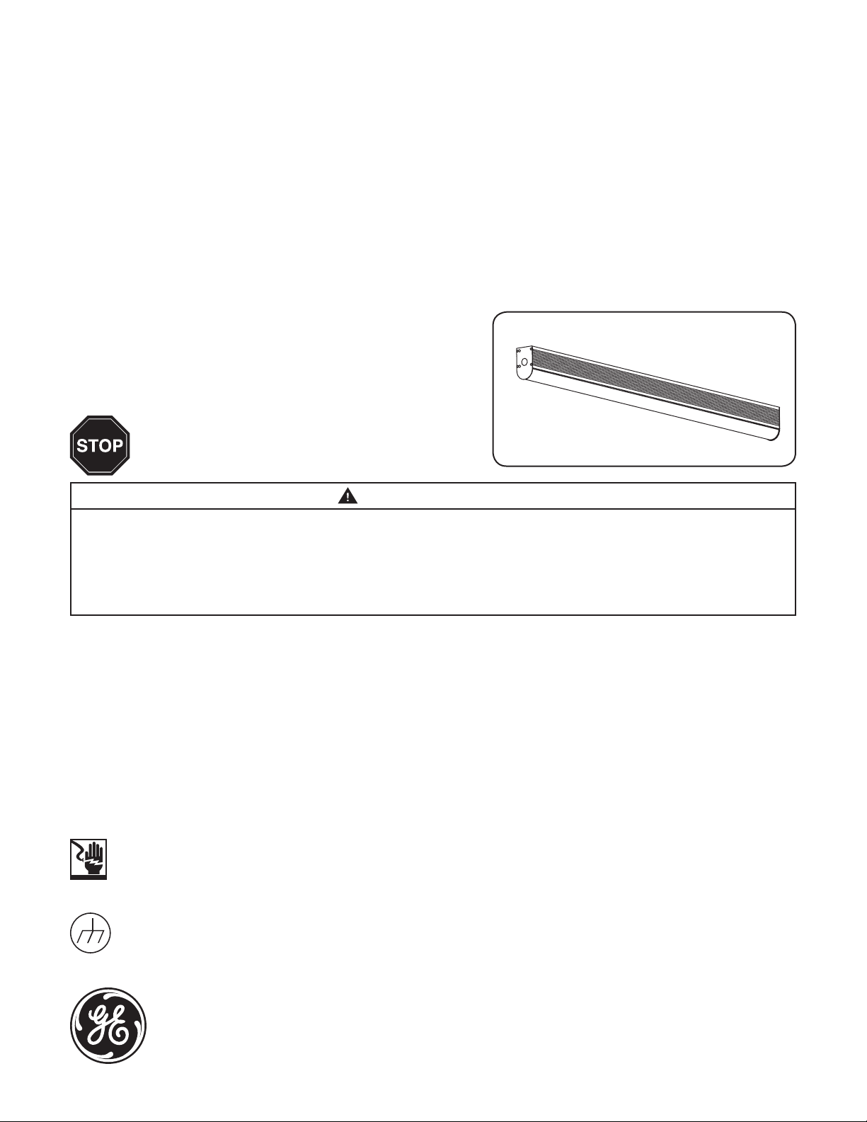
AlbeoTM LED Luminaire
Linear Lighting
(ALC4-series)
Features
• 5 year warranty
• Damp location rated
BEFORE YOU BEGIN
Read these instructions completely and carefully.
Installation Guide
WARNING/AVERTISSEMENT
RISK OF ELECTRIC SHOCK
• Turn power off before inspection, installation or removal.
• Properly ground electrical enclosure.
RISK OF FIRE
• Follow all NEC and local codes.
• Use only UL or IEC approved wire for input/output connections.
Minimum size 18 AWG.
This device complies with part 15 of the FCC Rules. Operation is subject to the following two conditions: (1) This device may not cause harmful interference, and
(2) this device must accept any interference received, including interference that may cause undesired operation. CAN ICES-3 (A)/NMB-3(A)
This equipment has been tested and found to comply with the limits for a Class A digital device, pursuant to part 15 of the FCC Rules. These limits are designed
to provide reasonable protection against harmful interference when the equipment is operated in a commercial environment. This equipment generates, uses,
and can radiate radio frequency energy and, if not installed and used in accordance with the instruction manual, may cause harmful interference to radio
communications. Operation of this equipment in a residential area is likely to cause harmful interference in which case the user will be required to correct the
interference at his own expense.
RISQUES DE DÉCHARGES ÉLECTRIQUES
• Coupez l’alimentation avant d’’inspecter, installer ou déplacer le luminaire.
• Assurez-vous de correctement mettre à la terre le boîtier d’alimentation électrique.
RISQUES D’INCENDIE
• Respectez tous les codes NEC et codes locaux.
• N’utilisez que des ls approuvés par UL ou IEC pour les entrées/sorties de
connexion. Taille minimum 18 AWG.
Save These Instructions
Use only in the manner intended by the manufacturer. If you have any questions, contact the manufacturer.
Prepare Electrical Wiring
Electrical Requirements
• The LED driver must be supplied with 120-480 VAC, 50/60 Hz per product label and connected to an individual
properly grounded branch circuit, protected by a 15 or 20 ampere circuit breaker.
Grounding Instructions
• The grounding and bonding of the overall system shall be done in accordance with National Electric Code
(NEC) Article 600 and local codes.
imagination at work
Page 2
Unit Installation
Carefully unpack unit and properly inspect for defects before installing. Wear work gloves to prevent dirt and oil from being
1
transferred to the luminaire.
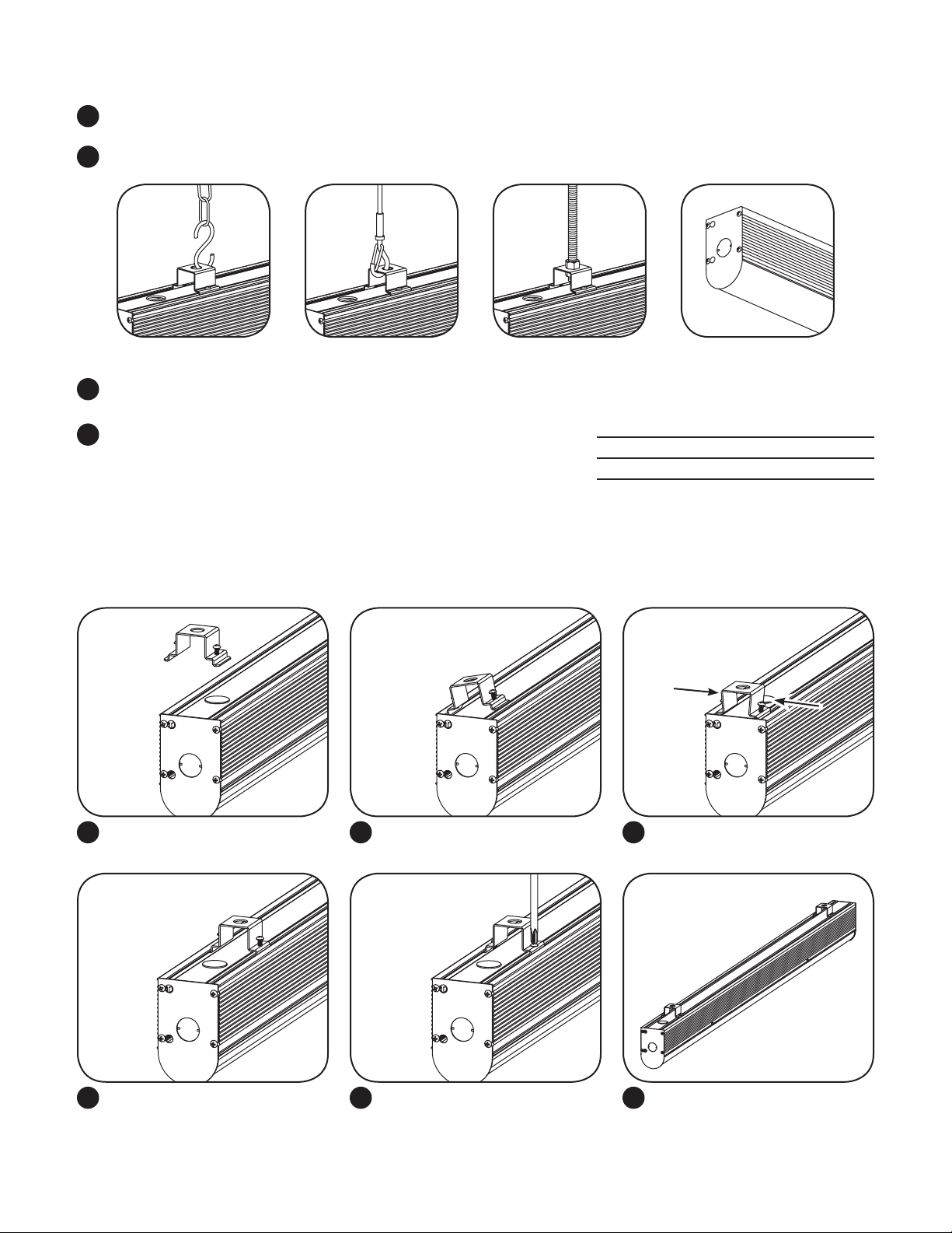
Choose a mounting method: chain, cable, rod or surface mount.
2
Chain Cable Rod Surface
Please follow all UL, NEC and minimum load rating guidelines
3
when selecting and installing a chain, cable or rod.
Hang up to two chains, cables or rods from a structural member of the
4
ceiling to support each xture. Fixture must be supported independently
of an outlet box. Install mounting brackets for each xture.
4 ft. xture 8.5 lbs. 11.5 lbs.
8 ft. xture 17 lbs. 20 lbs.
ALC4 Fixture Weight
120-277V 347/480V
Mounting Bracket Installation
The mounting bracket can be installed at any location along the length of the xture. Screws must be fully tightened to lock in place
and strengthen the bracket. Each mounting bracket can connect to a chain, cable or rod.
Mounting bracket (with #6-3/8” Phillips
1
head screws) and xture shown.
Fit one side of the bracket into an
2
extrusion slot on the xture.
Squeeze the mounting bracket and
3
press down until it snaps into place.
Position mounting bracket in
4
desired location.
Fully tighten screws to lock in
5
place and strengthen the bracket.
Fixture is now ready to install with
6
chain, cable or rod. If installing a
Continuous Run or Control Module,
please review additional instructions
later in this publication.
Page 3

Surface Mount Installation
Option A: Attach using mounting holes
Loosen screws
Open lightbar
Loosen screws on side of xture and unhinge LED lightbar
1
from xture.
Junction box
AC line
Ceiling
Use mounting holes on both ends
Using 3/8” holes on both ends, mount the xture to
2
ceiling using appropriate hardware (not supplied).
Junction box
Fixture wires
Run power through one of the 0.875” holes in top
3 4
of xture and into a junction box. Connect AC wires
from junction box to xture wires (see Step 4 under
Electrical Connections for details).
Option B: Attach directly to junction box
Loosen screws
Open lightbar
Reattach lightbar to xture and tighten screws.
Top of xture
Loosen screws on side of xture and unhinge LED lightbar
1
from xture.
Attach plate to top of xture and tighten with two nuts
2
on interior of xture. Run wiring out of 0.875” hole.
Page 4

Junction box
in ceiling
Close xture and tighten screws. Connect AC wires from
3 4
junction box to xture wires (see Step 4 under Electrical
Connections for details).
Mount xture to junction box.
Electrical Connections
Note: Please see additional wiring instructions if installing multiple xtures in a Continuous Run or an inline Control Module.
A) Conduit B) Power cord
Loosen screws to remove endcap. Option: power input from top – Remove knockout in top
1 2
and A) install 1/2” conduit, or B) install AC power cord
with strain relief.
A) Conduit B) Power cord
Option: power input from side – Remove knockout in
3 4
endcap and A) Install 1/2” conduit, or B) install AC power
cord with strain relief. Plug unused hole on top with
appropriate tting.
120-277V: Connect the green (ground), black (line)
and white (neutral) wires of the AC line to the similarly
colored wires of the xture’s power supply using UL
listed wire connectors. Re-attach endcap.
347-480V: Connect the green (ground), red (line) and
black (neutral) wires of the AC line to the similarly
colored wires of the xture’s power supply using UL
listed wire connectors. Re-attach endcap.
Page 5

Continuous Run Installation
When ordered as an option, continuous run xtures use quick-connectors and keyhole fasteners to properly wire & align the joining xtures.
First xture in run
Open end
Closed end
Completely hang the rst xture in the run. One end
1 2
should be closed while the other end has quick-connect
wiring. Using two people, hang the next xture in the run,
making sure to properly align quick-connectors.
Push the quick-connect assembly and excess wiring
3 4
into the open end of one xture end plate so only a
small length of wire remains between joining xtures.
Make all wiring connections between xtures using the
provided quick-connectors.
Align keyhole slots with corresponding keyhole studs and
push xtures together.
Shift xtures until keyhole studs lock-in place and xtures
5 6
are horizontally aligned
Continue to add xtures as needed to complete the
7
continuous run.
Note: If there are unused quick-connectors at the end
of a run, cut off the connectors and cap the ends with
wire connectors to terminate the wires. Replace open
end plate with a solid end plate.
Note: The current though the continuous xture run cannot
exceed 20A. See maximum xture run length listed below.
Install two #8-32 screws with nuts (provided) to fasten the
end plates of the joined xtures together
Output
Voltage
120V 288 192 120
277V 664 440 284
347V 677 495 342
480V 936 685 474
Total Run Length (ft.)
T H V
Page 6

Control Module Installation and Wiring
The 14” wireless control /occupancy sensor module can be installed inline with any xture conguration. The contractor must drop
power down to this module and connect any desired adjacent xtures to the module. Note: The occupancy sensor shown in these
images may differ from the actual unit provided.
Wireless control /occupancy sensor module The control module is attached the same as the continuous
run xtures.
Control Module Wiring Scheme
Each 14” wireless control / occupancy sensor module will power up to 48 ft. of xtures (maximum 24 ft. per side). Note: The xtures
between control sections must not be connected to each other. Power drops must be connected to the control modules.
NOTE: drawing not to scale
Etc.
Start of run
DO NOT connect the two xtures
at the end of each control section.
The xtures will not function
properly if they are connected to
Power drop
Control section 1 Control section 2
Wireless control/occupancy sensor module 8 ft. xture
multiple control modules.
Power drop
Troubleshooting
Symptom Solution
Luminaire will not turn on. • Check that the color of the supply side wires match the color of the wires they are connected to.
• Check that all wire connectors are properly connected.
• Verify that your input voltage is within specs.
• If you are using any additional controls IE wireless controls // motion sensors, please also verify that
those are working properly and that the unit is setup to interface with the controllers.
Mounting bracket slides
from side to side.
• Check that the mounting bracket is properly tightened using the adjustment screws provided.
GE Lighting • 1-888-MY-GE-LED (1-888-69-43-533) • www.gelighting.com
GE Lighting Solutions, LLC is a subsidiary of the General Electric Company. The GE brand, logo, and Albeo are trademarks of the General Electric Company.
© 2014 GE Lighting Solutions, LLC. Information provided is subject to change without notice. All values are design or typical values when measured under laboratory conditions.
ALB003-091114
 Loading...