

Page 1

GE
Lighting
™
Albeo
Linear Low Bay Lighting
(ALC4 - Series)
LED Luminaire
imagination at work
Page 2
Product Features
®
The Albeo™ ALC4-series LED luminaire is an energy-efficient, low maintenance alternative to traditional linear fluorescent
in a variety of commercial, low bay lighting applications. Compact and sleek in design, the ALC4 features a long rated life
of 77,000 hours (L70) and can deliver up to 600 feet of outstanding quality light in a continuous run configuration. Ideal for
industrial, commercial and light assembly applications, the Albeo ALC4 LED fixture can be matched with motion, daylight
and wireless controls for increased energy savings.
Applications
• Designed to meet recommended luminance and
illuminance requirements for low bay and task level
applications in commercial, industrial, warehouse,
office, education, health, retail and data center settings.
• Recommended for low bay lighting applications at
20 feet or lower.
Housing
• Rugged extruded aluminum housing.
• Each LED module is equipped with an upper limit
thermal control to ensure fixture lifetime throughout
the temperature range.
LED & Optical Assembly
• Precision lens system provides optimized illumination
for open floor plan and aisle layouts.
• Multiple photometric distributions of 20, 40, 80 and
120 degrees. Plus diffuse and wide lens options.
• Utilizes high brightness LEDs, 70, 80 and 90 CRI at
4000K & 5000K typical.
• LM-79, LM-80 tests and reports are performed in
accordance to IESNA standards.
• Directional LEDs put light where it’s needed without
reflectors to greatly increase efficiency.
Lumen Maintenance
Mounting
•
Chain, cable, 1/2” threaded rod, and surface mount.
• Continuous run option available.
Finish
• White polyester powder coat.
Controls
• Motion and Daylight sensor can be combined
for additional energy savings.
• For wireless controls please consult factory.
Electrical
• 120-277 volt and 347-480 volt available.
• System power factor is >90% and THD <20%.*
• Integral surge protection:
For 120-277VAC per IEEE/ANSI C62 41.1:1991, 4kV
IEC 61000-4-12.
• EMI: Title 47 CFR 15 Class A.
* System power factor and THD is tested and specified at 120V
input and maximum load conditions.
Warranty
• 5-year limited system warranty standard.
• System rating is L85 at 50,000 hours. Contact
manufacturer for Lxx rating (Lumen Depreciation)
beyond 50,000 hours.
Ratings
• DLC. Listed.
/
• UL 1598 Suitable for Damp Locations.
• UL 8750 LED equipment in Lighting Products.
•
Temperature Rated at (–30°C to 45°C) (-22°F to 113°F).
Industry Awards
•
Projected L70 (15K) > 77,000 Life Hours per IES TM-21.
=
Page 3
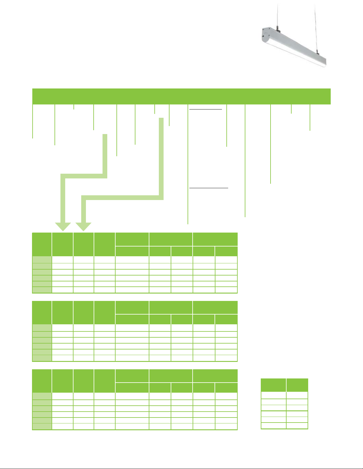
Ordering Number Logic
Albeo™ Linear Low Bay LED Lighting
A L C 4 1 W
_ _ _ _ - _ - _ - _ - _ _ - _ - _ - _ - _ - _ - _ _ - _ - _ - _ -
PRODUCT
A = Albeo
L = Linear
C = C-Series
4 = LED
MODULE
1 T 4ft 72 3200 30 37 107 86
1 H 4ft 144 5350 47 52 114 103
1 V 4ft 144 7400 71 76 104 97
1 T 8ft 144 6400 57 69 112 93
1 H 8ft 288 10700 94 103 114 104
1 V 8ft 288 14800 142 152 104 97
ID
Generation
CURRENT
#
VOLTAGE MODULE
0 = 120/277
1 = 120*
4 = 277*
5 = 480*
D = 347*
*Specify single
voltage only if
cord and plug
needed.
DRIVE
1 = 1 module
FIXTURE
LENGTH
CURRENT
T = Standard
H = High Output
V = Very High
Output
COUNT
DRIVE
LED
LED COLOR
70 Plus CRI
47 = 4000K
57 = 5000K
80 Plus CRI
48 = 4000K
58 = 5000K
90 Plus CRI
49 = 4000K
59 = 5000K
TYPICAL INITIAL
LUMENS 70 CRI
4000K/5000K
TEMP
OPTICS
BEAM
1 = 120°
2 = 20°
4 = 40°
8 = 80°
D =
Diffused
lens
W =
Wide
lens
FIXTURE
LENGTHS
4 = 4ft
S = Both
8 = 8ft
Ends
L = Left
R = Right
M = Open
End Cap
Configura
tions can
be found
on Page
3 of this
brochure.
WAT TS LPW
120-277V
MOTION/DAYLIGHT
END
CAP
347-480V 120-277V 347-480V
SENSOR
STAND ALONE FIXTURES
N = None
A = On/off motion aisle
B = On/off motion 360
C = On/off cold temp aisle
D = On/off cold temp 360
If you choose options
below you must choose
control wiring option V or D
E = Daylight sensor
F = Motion aisle/daylight
G = Motion 360/daylight
H = Pre-wired (no sensor)
J = 0-10V Motion 360
K = 0-10V Motion aisle
L = 0-10V Motion 360 cold
M = 0-10V Motion aisle cold
CONTINUOUS RUN FIXTURES
N = None
P = On/off motion 360
Q = On/off cold temp 360
R = Motion 360/daylight
T = 0-10V Motion 360
U = 0-10V Motion 360 cold
Note:
Only 1 sensor needed
for every 48 feet.
CONTROL
WIRING
N = None
V = 0-10V
Stand alone
D = 0-10V
Daisy chain
R =
Continuous
run wiring
CORD &
PLUG
ST = Standard
Fits chain, cable
and ½” threaded
rod.
51 = Cable/ Hook
5 ft. pair
52 = Cable/ Hook
10 ft. pair
53 = Cable/ Hook
15 ft. pair
54 = Cable/ Hook
20 ft. pair
SM = S urface
Mount*
*Not available with
continuous run
See Mounting &
Accessories
Note:
IES files located
on GE website
www.gelightingsolutions.com
K = Knock out
access plug
A = 6 ft. 18-3
cord & twist
lock 15 amp
plug
B = 6 ft. 18-3
cord only
C = 12 ft. 18-3
cord & twist
lock 15 amp
plug
D = 12 ft . 18-3
cord only
See
factory for
custom cord
lengths.
FINISH OPTIONSMOUNTING
W = White
Powder coat
*W = Wireless
*Please consult
factory for
wireless
application
TYPICAL INITIAL
MODULE
1 T 4ft 72 2700 30 37 90 73
1 H 4ft 144 4500 47 52 96 87
1 V 4ft 144 6200 71 76 87 82
1 T 8ft 144 5400 57 69 95 78
1 H 8ft 288 9000 94 103 96 87
1 V 8ft 288 12400 142 152 87 82
MODULE
1 T 4ft 72 2350 30 37 78 64
1 H 4ft 144 3900 47 52 83 75
1 V 4ft 144 5350 71 76 75 70
1 T 8ft 144 4700 57 69 82 68
1 H 8ft 288 7800 94 103 83 76
1 V 8ft 288 10700 142 152 75 70
DRIVE
CURRENT
#
DRIVE
CURRENT
#
FIXTURE
LENGTH
FIXTURE
LENGTH
LED
COUNT
LED
COUNT
LUMENS 80 CRI
4000K/5000K
TYPICAL INITIAL
LUMENS 90 CRI
4000K/5000K
WAT TS LPW
120-277V
120-277V
347-480V 120-277V 347-480V
WAT TS LPW
347-480V 120-277V 347-480V
Note: Lumen data shown is for 120 deg (1) optic. See tabel at right for other light optic factors.
OPTICS
BEAM
120 (1) 100%
20 (2) 94%
40 (4) 92%
80 (8) 97%
Diffused (D) 87%
Wide (W) 97%
%
OUTPUT
Page 4

End Cap Configuration
See page 2 for complete ordering number logic
Left Right
S =
L =
Stand Alone
Fixture
Both End Caps
Continuous
Run Fixture
Left End Cap
R =
M =
Continuous
Run Fixture
Right End Cap
Continuous
Run Fixture
Open End Caps
(Middle)
Page 5

Photometrics
Spacing Criteria:
Spacing Crite
g
r
0° = 1.88
.8
90° = 0.56
90
Spacing Criteria:
Spacing Crite
g
r
0° = 1.49
.4
90° = 0.66
90
Spacing
g
r
0° = 1.28
.2
90° =
90
Spacing Criteria:
Spacing Crite
g
r
0° = 1.32
.3
90° = 1.28
9099
Spacing Criteria:
Spacing Crite
g
r
0° = 1.21
.2
90° = 1.30
9
Spacing Criteria:
Spacing Crite
grSpaci
0° = 1.30
90° = 2.27
90
Optics for Common Applications
Aisle Distribution
20° Full Beam Angle
VA: 0° 10° 20° 30° 40°
Standard Distribution
80° Full Beam Angle
90°
80°
70°
60°
50°
90°
80°
70°
60°
50°
Narrow Distribution
40° Full Beam Angle
90°
80°
70°
60°
50°
VA: 0° 10° 20° 30° 40°
Standard Distribution
120° Full Beam Angle
90°
80°
70°
60°
50°
VA: 0° 10° 20° 30° 40°
120° Diffused
90°
80°
70°
60°
50°
VA: 0° 10° 20° 30° 40°
VA: 0° 10° 20° 30° 40°
160° Wide Beam Angle
90°
80°
70°
60°
50°
VA: 0° 10° 20° 30° 40°
Lens selection by application
The Albeo™ ALC4-series optical lens system enables LEDs to provide precise illumination where needed. Lenses are
designed for commercial & industrial applications where mounting height, fixture spacing & light levels help determine lens
selection. The following table outlines lens options and suggested application. Consult factory for specific project layouts.
LENS TYPE MOUNTING HEIGHT SPACE TYPE
80°, 120°, Diffused, Wide Beam Below 20 Feet Open Floor Plan
20°, 40° Below 20 Feet Low Bay Aisles
Page 6

Mounting & Accessories
MOUNTING OPTIONS IMAGE ORDER LOGIC CODE
Chain/Cable/Rod
Mount
Standard Chain/Cable/Rod Mount
Available on all fixture configurations
(chain, cable or rod not included). Cable
Hook can be ordered as an accessory.
ST = Standard
Cable Hook (optional)
Use with Standard cable/chain/rod mount.
Order separately. Price adder per pair.
5 ft., 10 ft ., 15 ft ., 20 ft . lengths available.
Option A
Surface Mount (optional)
Not available with continuous run.
Option B
Surface Mount (optional)
Not available with continuous run.
51=Cable-Hook-05ft-Pair
52=Cable-Hook-10ft-Pair
53=Cable-Hook-15ft-Pair
54=Cable-Hook-20ft-Pair
Chain/Cable/Rod mount is standard and included
in price. Additional price for Cable Hook. See
“Installation Instructions” for mounting details.
SM = Surface Mount
ALC4 can be mounted to a surface using holes
predrilled in the bottom fixture or to a junction
box using the mounting plate provided. See
“Installation Instructions” for more details.
Page 7

14.12”
Product Dimensions
48”
2.43”
48”
2.43”
96”
Albeo™ Linear Low Bay LED Lighting
(ALC4 - 4 ft./8 ft .)
4.80”
2.43”
End View
Top View
48”
3.87”
2.43”
96”
Side View
Weight:
120-277V: 8 lbs.
347/480V: 11 Lbs.
Wireless Control/Occupancy Sensor Module
Weight: 2.5 lbs.
4.72”
2.57”
End View
Weight:
120-277V: 16 lbs.
347/480V: 19 Lbs.
14.12”
Top View
Side View
Note: The occupancy sensor shown
is a representative example
Page 8

www.gelighting.com
GE and the GE Monogram are trademarks of the General Electric Company. All other trademarks are the property
of their respective owners. Information provided is subject to change without notice. All values are design or typical
values when measured under laboratory conditions. GE Lighting and GE Lighting Solutions, LLC are businesses of
the General Electric Company. © 2014 GE.
ALB004 (Rev 09/15/14)
 Loading...