

Page 1
Smart Card Reader • AL-1191, AL-1193
Installation Instructions
1040736C • February 2007
Copyright © 2007, GE Security Inc.
Introduction
This is the GE Smart Card Reader Installation Instructions for
models AL-1191 and AL-1193. The smart card reader is a multifunction, all-purpose proximity card reader suitable for all locations (including outdoors) that require a short-range reader. You
can connect the reader directly to the Alliance system RS485
databus.
You can configure the reader through the control panel menu
when it is connected to the system databus, through the DGP
menu when it is connected to the local databus, or you can use a
configuration card. Refer to the Smart Card Reader Program-
ming Manual for more information.
The AL-1191 model is shipped with a white removable cover
(there are five other colors available).
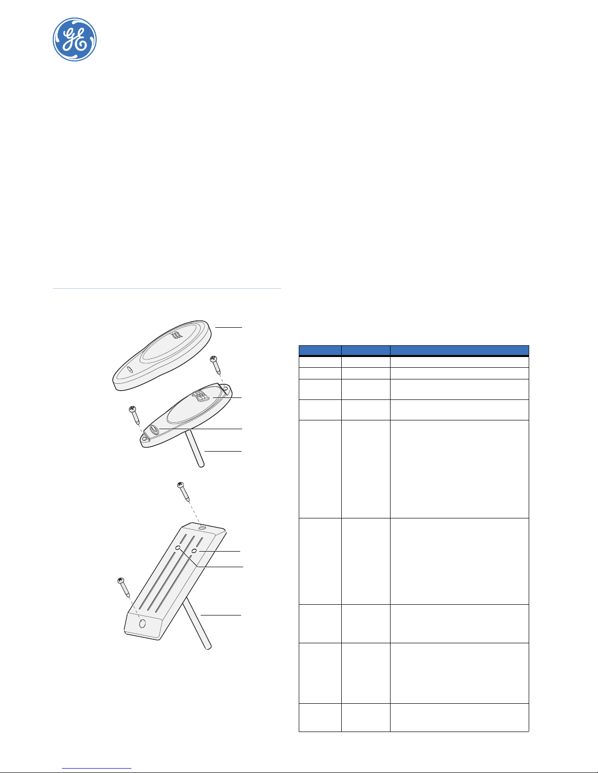
Reader components
Figure 1 shows the reader components.
Figure 1. Reader components
AL-1191
AL-1193
Blue LED. Door open, disarmed.
Red LED. Door open, armed
Comms. LED control, buzzer control, power.
Cover
Blue LED
Red LED
Comms
Blue LED
Red LED
Comms
Installation
You should program the reader and change the default address
(16) before you install the reader. Refer to the Smart Card
Reader Programming Manual for programming details.
You can mount the reader on any flat surface with two #6 (3 to
3.5 mm diameter) panhead screws (Figure 1). We do not recommend using countersunk screws.
You will experience a slightly reduced range if you mount the
reader on a metal surface. If you mount the AL-1191 reader
outdoors, ensure that the blue LED is at the top.
To mount the reader, do the following:
1. Gently pry the AL-1191 cover sides away from the main
reader body to remove cover and expose the mounting
screws. Do not use excessive force or the reader can be
irreparably damaged.
2. Mount the reader using the mounting screws.
3. Gently press the cover over the main body of the AL-1191
reader until it locks into place.
Wiring
Table 1 describes the reader wiring components.
Table 1. Wiring components
Wire color Name Description
Red Positive 9 to 14 VDC supply.
Black 0 V DC supply ground.
Green D-/D0/Data RS485 Data -, Wiegand Data 0
White D+/D1/Clock RS485 Data +, Wiegand Data 1
Brown LED 1 Offline LED control configured to two-wire
Yellow LED 2 Configurable to control the blue LED when
Blue Buzzer Offline buzzer control.
Violet Open collector Configurable as: door relay, tamper output,
470 ohm
resistor
Absolute maximum, 12 V at 10 mA
Absolute maximum, 12 V at 10 mA
control will control the red LED only.
Wire grounded: red LED on
Wire open: red LED off
Wire at +5 to +12 V: red LED off
Offline LED Control conf igured to one-wire
control will control both the red and blue LEDs
Wire grounded: blue LED on
Wire open circuit: both LEDs off.
Wire at +5 V to +12 V: red LED on.
Absolute maximum, 14 V
offline.
Wire grounded: blue LED on.
Wire open: blue LED off.
Wire at +5V to +12V: blue LED off.
Request-to-exit input when online to Alliance.
This input may be connected to a push button
connected to ground with RTE only selected on
the option card or in Menu 10. Refer to the
Smart Card Reader Programming Manual.
Wire open or +5V to +12V: buzzer off.
Wire grounded: buzzer sounding.
Absolute maximum, 14 V.
credit controlled pulse, timed, or latched
output.
Absolute maximum, 14 V at 25 mA
This is a low current output and must not be
used to directly energize high current door
openers.
Used to terminate RS485 bus when the reader
is the last device on the bus.
Install across D+ (white) and D- (green).
Page 2
Smart Card Reader
2
Installation Instructions
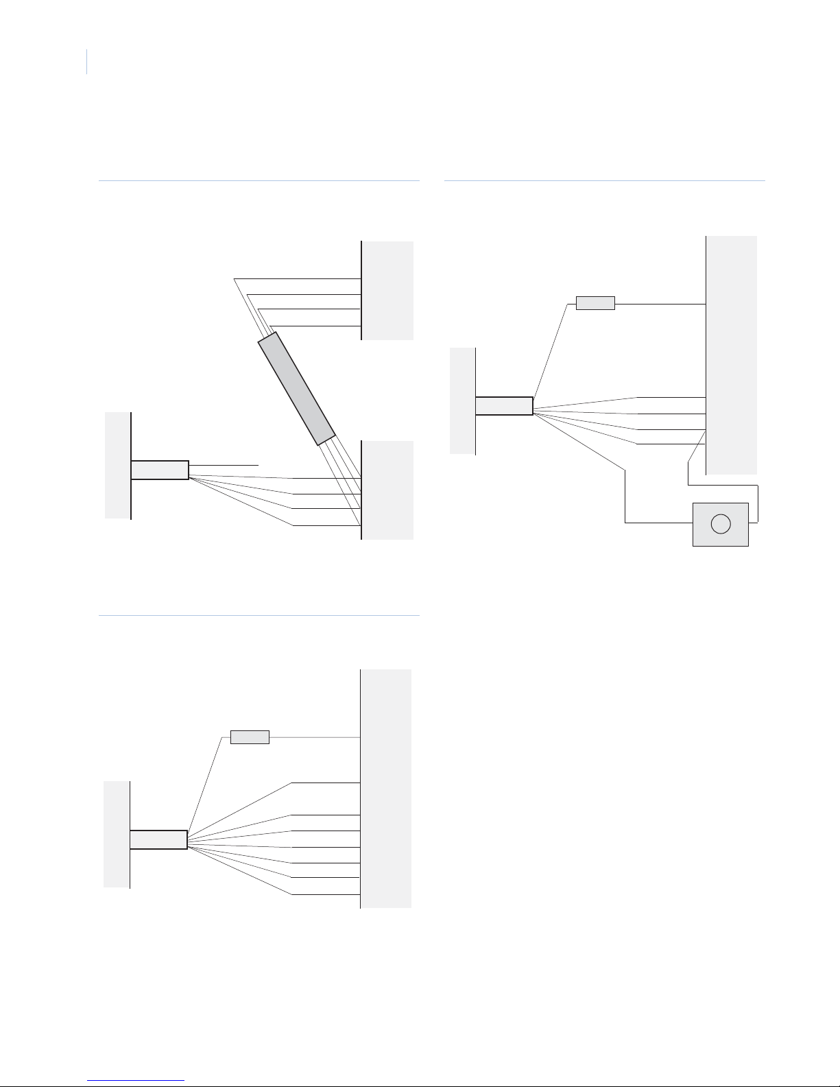
System bus connections
Figure 2 shows how to connect the reader to a RAS on the Alliance system bus.
Figure 2. System bus connections
Control
panel
Green
White
Black
Red
System bus
AL-1191/AL-1193
Violet (open collector)
Green
White
Black
Red
J10
DD+
0V
+12V
RAS
DD+
0V
+12V
Local bus connections
Figure 4 shows how to connect the reader to a 4-Door/Elevator
Controller DGP local bus with a request-to-exit input.
Figure 4. Local bus connections
DGP
J8 to J12
1
C
2
C
3
C
J22
D-
D+
0V
+12V
BZ
AL-1191/AL-1193
4K7
Violet
Green
White
Black
Red
Yellow
Wiegand block connections
Figure 3 shows how to connect the reader to the Wiegand
connection block on a 4-Door/Elevator Controller DGP.
Figure 3. Wiegand block connections
J8 to J12
1
C
2
C
3
C
J13 to J16
+12V
+5V
0V
D0
D1
L2
L1
BZ
AL-1191/AL-1193
4K7
Violet
Red
Black
Green
White
Yellow
Brown
Blue
DGP
Request-to-exit
Tamper
The reader has a tamper feature. When the reader is connected to
the system databus, tamper data is transmitted to the Alliance
system with system data. You can configure a tamper control for
both online and offline operation using an external open collector
output (violet wire)
Page 3

3
FCC compliance
This device complies with part 15 of the FCC rules. Operation is subject to the
following conditions:
1. This device may not cause harmful interference.
2. This device must accept any interference received, including interference
that may cause undesired operation.
Changes or modifications not expressly approved by the party responsible for
compliance could void the user’s authority to operate the equipment.
This equipment has been tested and found to comply with the limits for a Class
B digital device, pursuant to Part 15 of the FCC Rules. These limits are designed
to provide reasonable protection against harmful interference in a residential
installation. This equipment generates, uses, and can radiate radio frequency
energy and, if not installed and used in accordance with the instructions, may
cause harmful interference to radio communication. However, there is no guarantee that interference will not occur in a particular installation.
If this equipment does cause harmful interference to radio or television reception, which can be determined by turning the equipment off and on, the user is
encouraged to try to correct the interference by one or more of the following
measures:
Reorient or relocate the receiving antenna.
Increase the separation between the equipment and receiver.
Connect the equipment into an outlet or a circuit different from the one
where the receiver is connected.
Consult the dealer or an experienced ratio-TV technician for help.
FCC ID: CGGATS1190-1192.
Specifications
Current consumption
Standby
Active
Input voltage 9 to 14 VDC
Operating temperature 32 to 120°F (0 to 49°C)
Humidity 85% noncondensing
Listings UL 294 Standard for Access Control System
25 mA
80 mA maximum
Units
UL 365 Standard for Police Station
Connected Burglar Alarm Units and Systems
UL 609 Standard for Local Burglar Alarm
Units and Systems
UL1610 Standard for Central Station Burglar
Alarm Units
UL 1635 Standard for Digital Alarm Commu-
nicator System Units
Toll-free: 888.GESECURity (888.437.3287 in the US, including Alaska and Hawaii; Puerto Rico; Canada).
Technical support
Outside the toll-free area: Contact your local dealer.
www.gesecurity.com
 Loading...