

Page 1
8-Area LCD RAS • AL-1103, AL-1108
Installation Instructions
1040972B • February 2007
Copyright © 2007, GE Security Inc.
Introduction
This is the GE 8-Area LCD RAS Installation Instructions for
models AL-1103 and AL-1108. The RAS is the primary user
interface for navigating system programming, doing simple data
entry, and controlling the Alliance system alarm and access
control functions. The scrolling text, Liquid Crystal Display
(LCD) displays data entry, system status messages, programming
menus, and function options. These can be accessed and selected
through the alphanumeric digital keypad (Figure 1). The
AL-1108 model is also fitted with a card reader option.
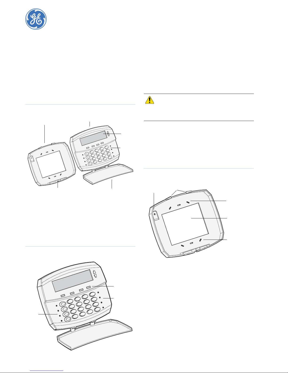
Figure 1. RAS components
Mounting plate
Cover lock screw
Cover
LCD
Keypad
Door
You can mount the RAS up to 5,000 ft. (1.5 km) from the control
panel. If the distance between the RAS and the control panel
does not exceed 328 ft. (100 m), you can power the RAS using
the +12V and 0V terminals from the control panel. When the
distance exceeds 328 ft. (100 m), use the AUX PWR terminal
from a DGP or an auxiliary power supply. If you use AUX PWR ,
you must connect the 0V from the control panel to the 0V on the
DGP or auxiliary power supply.
CAUTION: You must be free of static electricity
before handling circuit boards. Wear a
grounding strap or touch a bare metal
surface to discharge static electricity.
Installation
To install the unit, do the following:
1. Locate the cover lock screw on the bottom of the unit and
unscrew it until you can lift the cover off the mounting plate
(Figure 1).
2. Use the mounting plate to locate and install mounting
anchors where needed (Figure 3).
Figure 3. Mounting plate
Tamper
screw
Cover
guides
The LCD is backlit and the keypad is low-level illuminated, or in
case of poor lighting conditions, may be programmed for highlevel illumination. The LCD backlight remains illuminated for
30 seconds after the last key press. The keypad high-level illumination remains active for four minutes after the last key press.
You can program the eight red area LEDs (four on each side of
the keypad) in Figure 2 to indicate the status for areas 1 to 8 or
areas 9 to 16. The four larger status LEDs indicate power (green),
system trouble (yellow), alarms red), and access (blue).
Figure 2. Cover LEDs
Area
LEDs
Power
Fault
Alarm
Access
Status LEDs
Area LEDs
Mounting holes
Cable entry
Mounting holes
3. Pull the wiring through the cable entry and screw the
mounting plate to the wall. If a pry-off tamper is required,
use a screw in the tamper hole on the mounting plate
(Figure 3).
4. Wire the circuit board. Turn off all power to the control
panel before wiring the unit. See Wiring on page 2.
5. Set the DIP switches as needed. See DIP switch settings on
page 3.
6. Insert the cover in the guides at the top of the mounting
plate (Figure 3), pull the cover down, and tighten the cover
lock screw at the bottom of the unit (Figure 1).
7. Refer to your Alliance system programming documentation
for keypad operation and system programming.
Page 2
8-Area LCD RAS
2
Installation Instructions
Wiring
Figure 4 shows the J1 and J4 (AL-1108 only) wiring terminal
block locations.
Figure 4. Wiring terminals
DIP
Switches
Mode Add
1234
ABCT
J4
CLK DATA 0V +12V OUT IN D- D+ 0V +14V
J4 Terminal
block
J1 Terminal
block
J1 terminal block
Figure 5 shows optional wiring features for the J1 terminal block
and Table 1 describes the terminals .
Figure 5. Typical J1 wiring
Optional door
control or
auxiliary relay
12 V relay
50 mA max.
Optional egress
push-button
Table 1. J1 wiring terminals
Terminal Description
+14V, 0V Power supply.
D+ Data positive connection of the databus (LAN).
D- Data negative connection to the databus (LAN).
IN A request-to-exit (egress) button (normally open,
OUT Open collector output, 50 mA maximum. It is the first
momentary push-button switch), can be connected
across the In and 0V terminals. When pressed, this
button controls the request-to-exit function.
output of the output control group that is assigned to
this RAS. Refer to your Alliance system programming
documentation for details.
TX1
RX1
J1
Polling
LEDs
J1
+14V
0V
D+
D-
IN
OUT
J4 terminal block (AL-1108 only)
Figure 6 shows how to connect the J4 terminals to a Wiegand
interface (not for 5V readers) and Table 2 describe s the termi-
nals.
Figure 6. J4 wiring
Wiegand
interface
Red
Black
White
Green
Table 2. J4 wiring terminals
Terminal Description
+12V, 0V Power supply
CLK, DATA Communication lines.
Note: Shielded cable must be used (Belden 8723 or equivalent).
+12V
VSS(0V)
DATA
CLK
J4
LEDs
The unit provides status, area, and polling LEDs.
Status LEDs
The large status LEDs (Figure 2 on page 1) indicate:
Power. Green LED illuminates if AC power is available to
the system.
Fault. Yellow LED illuminates for system faults or trouble.
Alarm. Red LED illuminates on any alarm in an area
assigned to the keypad.
Access. Blue LED illuminates on both the AL-1103 and
AL-1108 when certain system trouble conditions occur
(missing battery). The LED also illuminates on the AL-1108
when access is granted.
Area LEDs
The eight small red area LEDs (Figure 2 on page 1) illuminate
when areas 1 to 8 or 9 to 16 are armed. The LEDs will flash on
alarm.
Polling LEDs
The two polling LEDs (Figure 4) indicate:
RX. The RX LED flashes when polling data is being
received on the system databus (LAN) from the control
panel. If the LED does not flash, the control panel is not
operational or the databus (LAN) is faulty (usually cabling).
TX. The TX LED flashes when the RAS is replying to
polling from the control panel. If the RX LED flashes but
the TX LED does not, the RAS is not programmed to be
polled in the control panel or is addressed incorrectly.
Page 3

3
DIP switch settings
The unit provides Mode and Address DIP switches (Figure 4 on
page 2).
The mode DIP switches indicate:
A (area).
Off. The eight area LEDs display the status of areas 1 to 8.
On. The eight area LEDs display the status of areas 9 to 16.
B (keypad backlight)
Off. The keypad backlight stays on low-level continuously.
On. The keypad high-level backlight times out after
approximately four minutes.
C (card reader type)
Off. Magnetic stripe card reader.
On. Wiegand card reader.
T (term)
Off. Not the last device on the databus (LAN).
On. Terminates the databus, this RAS is either the first or
last device on the databus (LAN).
The address DIP switches identify the RAS address. Figure 7
shows address settings.
Figure 7. Address DIP switch settings
All off
RAS 1 RAS 2 RAS 3 RAS 4
Function key covers
If the F1, F2, F3, or F4 keys are not required, you can snap the
function key blanking covers provided with the unit over the
keys. Function keys are freely programmable with Alliance
management software.
Power up
Upon initial power up:
• The beeper will sound two beeps indicating the internal
nonvolatile memory is okay.
• All of the area LEDs will illuminate, indicating that the
system is armed. You will need t o disarm all a reas to enabl e
access to the installer programming menu options.
Troubleshooting
• There is no LED or LCD display.
Verify the +13.8 and 0V wire connections on both the RAS
and the power supply.
Verify power output on the DGP or external power supply.
• Area and status LEDs are flashing and the LCD display
reads “System Fault”.
Verify the D+ and D- wire connections (may be reversed).
Verify the address DIP switches are set to the proper
address.
Verify that the control panel or DGP is polling the RAS
address.
• Area LEDs will not display armed ares.
Verify that mode DIP switch A is set to the proper area
display mode.
RAS 5 RAS 6 RAS 7 RAS 8
RAS 9 RAS 10 RAS 11 RAS 12
RAS 13 RAS 14 RAS 15 RAS 16
All on
Page 4

8-Area LCD RAS
4
Installation Instructions
FCC compliance
This device complies with part 15 of the FCC rules. Operation is subject to the
following conditions:
1. This device may not cause harmful interference.
2. This device must accept any interference received, including interference
that may cause undesired operation.
Changes or modifications not expressly approved by the party responsible for
compliance could void the user ’s authority to operate the equipment.
Note: In order to maintain compliance with FCC Class B rules,
shielded cable must be used (Belden 8723 or equivalent).
Specifications
Supply voltage 9 to 14 VDC
Current consumption
AL-1103
AL-1108
Dimensions (W x H x D) 6 x 4.5 x 1 in. (152 x 114 x 25 mm)
Operating temperature 32 to 120°F (0 to 49°C)
Humidity 85% noncondensing
Listings UL 294, UL 365, UL 609, UL 1610, UL 1635
120 mA maximum
140 mA maximum
Toll-free: 888.GESECURity (888.437.3287 in the US, including Alaska and Hawaii; Puerto Rico; Canada).
Technical support
Outside the toll-free area: Contact your local dealer.
www.gesecurity.com
 Loading...