

Page 1
GE Healthcare
Life Sciences
ÄKTAprime™ plus
Operating Instructions
Original instructions
Page 2

Page 3

Table of Contents
Table of Contents
51 Introduction ..........................................................................................................
61.1 Important user information .............................................................................................................
71.2 Regulatory information ......................................................................................................................
101.3 Instrument ...............................................................................................................................................
131.4 Monitoring and evaluation ...............................................................................................................
141.5 User documentation ...........................................................................................................................
162 Safety instructions ...............................................................................................
162.1 Safety precautions ...............................................................................................................................
242.2 Labels .........................................................................................................................................................
262.3 Emergency procedures ......................................................................................................................
272.4 Recycling information .........................................................................................................................
282.5 Declaration of Hazardous Substances (DoHS) ........................................................................
313 Installation ............................................................................................................
313.1 Site requirements ..................................................................................................................................
313.2 Transport ..................................................................................................................................................
323.3 Unpacking ................................................................................................................................................
323.4 Connections ............................................................................................................................................
323.5 Spare parts and accessories ...........................................................................................................
334 Operation ..............................................................................................................
334.1 Operation overview .............................................................................................................................
334.2 Starting the instrument ......................................................................................................................
344.3 Preparations before start ..................................................................................................................
394.4 Performing a run ...................................................................................................................................
414.5 Procedures after a run .......................................................................................................................
435 Maintenance .........................................................................................................
435.1 General ......................................................................................................................................................
445.2 User maintenance schedule ...........................................................................................................
465.3 Cleaning ....................................................................................................................................................
475.4 Component maintenance ................................................................................................................
475.5 Disassembly and assembly of components and consumables .....................................
485.6 Calibration ................................................................................................................................................
495.7 Storage ......................................................................................................................................................
506 Troubleshooting ...................................................................................................
506.1 UV curve problems ...............................................................................................................................
516.2 Conductivity curve problems ..........................................................................................................
536.3 pH curve problems ...............................................................................................................................
566.4 Pressure curve problems ..................................................................................................................
ÄKTAprime plus Operating Instructions 28-9597-89 AB 3
Page 4

Table of Contents
577 Reference information ........................................................................................
577.1 Specifications .........................................................................................................................................
577.2 Chemical resistance ............................................................................................................................
617.3 System recommendations ...............................................................................................................
627.4 Health and Safety Declaration Form ...........................................................................................
647.5 Ordering information ..........................................................................................................................
65A Connection diagram - Liquid flow path ...........................................................
66B Tubing ....................................................................................................................
4 ÄKTAprime plus Operating Instructions 28-9597-89 AB
Page 5

1 Introduction
Purpose of the Operating
Instructions
The OperatingInstructions provide you withthe instructions needed to handleÄKTAprime
plus in a safe way.
Prerequisites
In order to operate ÄKTAprime plus as is intended, the following pre-requisites must be
fulfilled:
•
The user should have a general understanding of how a PC and the Microsoft™
Windows™ operating system works. (if a computer is used)
•
The user must understand the concepts of liquid chromatography.
•
The user must read and understand the Safety Instructions in this manual.
•
ÄKTAprimeplus andsoftware shouldbe installed, configured and calibratedaccording
to these Operating Instructions.
1 Introduction
About this chapter
This chapter contains important user information, a description of the intended use of
ÄKTAprime plus, regulatory information, list of associated documentation, definitions of
safety notices and so on.
ÄKTAprime plus Operating Instructions 28-9597-89 AB 5
Page 6

1 Introduction
1.1 Important user information
1.1 Important user information
Read this before operating
ÄKTAprime plus
All users must read the entire Operating Instructions before installing, operating or
maintaining ÄKTAprime plus.
Always keep the Operating Instructions at hand when operating ÄKTAprime plus.
Do notoperate ÄKTAprime plusin any otherway than described in the user documentation. If you do, you may be exposed to hazards that can lead to personal injury and you
may cause damage to the equipment.
Intended use
ÄKTAprime plus is a compact liquid chromatography system designed for one-step purification of proteins at laboratory scale.
ÄKTAprime plus is intended for research use only, and shall not be used in any clinical
procedures, or for diagnostic purposes.
Safety notices
This user documentation contains WARNINGS, CAUTIONS and NOTICES concerning the
safe use of the product. See definitions below.
Warnings
WARNING
WARNING indicates a hazardous situation which, if not avoided,
could resultin death or serious injury. It is important not to proceed
until all stated conditions are met and clearly understood.
6 ÄKTAprime plus Operating Instructions 28-9597-89 AB
Page 7
Cautions
Notices
Notes and tips
Note:
Tip:
1 Introduction
1.1 Important user information
CAUTION
CAUTION indicates a hazardous situation which, if not avoided,
could result in minor or moderate injury. It is important not to
proceed untilall stated conditions are metand clearly understood.
NOTICE
NOTICE indicates instructions that must be followed to avoid
damage to the product or other equipment.
A note is used to indicate information that is important for trouble-free and
optimal use of the product.
A tip contains useful information that can improve or optimize your procedures.
Typographical conventions
Software items are identifiedin the text by bold italic text. A colon separates menulevels,
thus File:Open refers to the Open command in the File menu.
Hardware items are identified in the text by bold text (e.g., Power switch).
1.2 Regulatory information
In this section
This section describes the directives and standards that are fulfilled by ÄKTAprime plus.
ÄKTAprime plus Operating Instructions 28-9597-89 AB 7
Page 8
1 Introduction
1.2 Regulatory information
Manufacturing information
The table below summarizes the required manufacturing information. For further information, see the EC Declaration of Conformity document.
manufacturer
CE conformity
This product complies with the European directives listed in the table, by fulfilling the
corresponding harmonized standards.
A copy of the EC Declaration of Conformity is available on request.
ContentRequirement
GE Healthcare Bio-Sciences AB, Björkgatan 30,Name and address of
SE-751 84 Uppsala, Sweden
TitleDirective
Machinery Directive (MD)2006/42/EC
Low Voltage Directive (LVD)2006/95/EC
CE marking
Electromagnetic Compatibility (EMC) Directive2004/108/EC
The CE marking and the corresponding Declaration of Conformity is valid for the instrument when it is:
•
used as a stand-alone unit, or
•
connected to other CE marked instruments, or
•
connected to other products recommendedor describedin theuser documentation,
and
•
used inthe same stateas it was delivered from GEHealthcare, except for alterations
described in the user documentation.
8 ÄKTAprime plus Operating Instructions 28-9597-89 AB
Page 9

International standards
This product fulfills the requirements of the following standards:
1 Introduction
1.2 Regulatory information
NotesDescriptionStandard
EN/IEC 61010-1,
UL 61010-1,
CAN/CSA-C22.2
No. 61010-1
EN 61326-1
EN ISO 12100
Regulatory compliance of
connected equipment
Any equipment connected to ÄKTAprime plus should meet the safety requirements of
EN 61010-1/IEC 61010-1, or relevant harmonized standards. Within the EU, connected
equipment must be CE marked.
Environmental conformity
Safety requirements for electrical
equipment for measurement,
control, and laboratory use
Electrical equipmentfor measurement, control and laboratory use
- EMC requirements
Safety of machinery. General
principles for design. Risk assessment and risk reduction.
EN standard is harmonized
with EU directive
2006/95/EC
EN standard is harmonized
with EU directive
2004/108/EC
EN ISO standard is harmonized with EU directive
2006/42/EC
TitleRequirement
Restriction of Hazardous Substances (RoHS) Directive2011/65/EU
2012/19/EU
Regulation (EC) No
1907/2006
ACPEIP
ÄKTAprime plus Operating Instructions 28-9597-89 AB 9
Waste Electricaland ElectronicEquipment (WEEE) Directive
Registration, Evaluation, Authorization and restriction
of CHemicals (REACH)
Administration on the Control of Pollution Caused by
Electronic Information Products, China Restriction of
Hazardous Substances (RoHS)
Page 10
1
2
3
4
5
6 7
8
9
10
17
16
15
14
13
12
11
1 Introduction
1.3 Instrument
1.3 Instrument
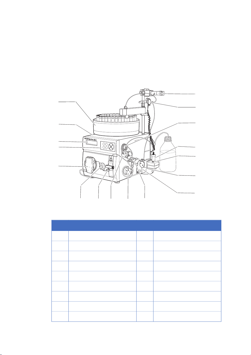
Product description
ÄKTAprime plus is a compact liquid chromatography system designed for one-step purification of proteins at laboratory scale.
Figure 1.1: The main parts of the instrument.
FunctionPartFunctionPart
Switch valve10Fraction collector1
Conductivity cell11Monitor and controller2
Flow restrictor12LCD display3
UV flow cell13Push buttons4
Column14Pump5
Sample loop15Pressure sensor6
Flow diversion valve16Mixer7
Column holder17Injection valve8
10 ÄKTAprime plus Operating Instructions 28-9597-89 AB
Buffer valve9
Page 11
The Power switch is located at the rear of the system.
l
0
l
0
Drop Sensor
Frac Valve
RS-232
Recorder
Rec. On/off
pH-Ground
pH-Probe
Conductivity Flow Cell
UV
UV-lamp
Mains
Voltage
220-240 V
100-120 /
Power max
90 VA
autorange
~
Frequency
50-60 Hz
(SYSTEM NO.)
(CODE NO.)
1
2
3
4
5
6
7
8
9
10
11
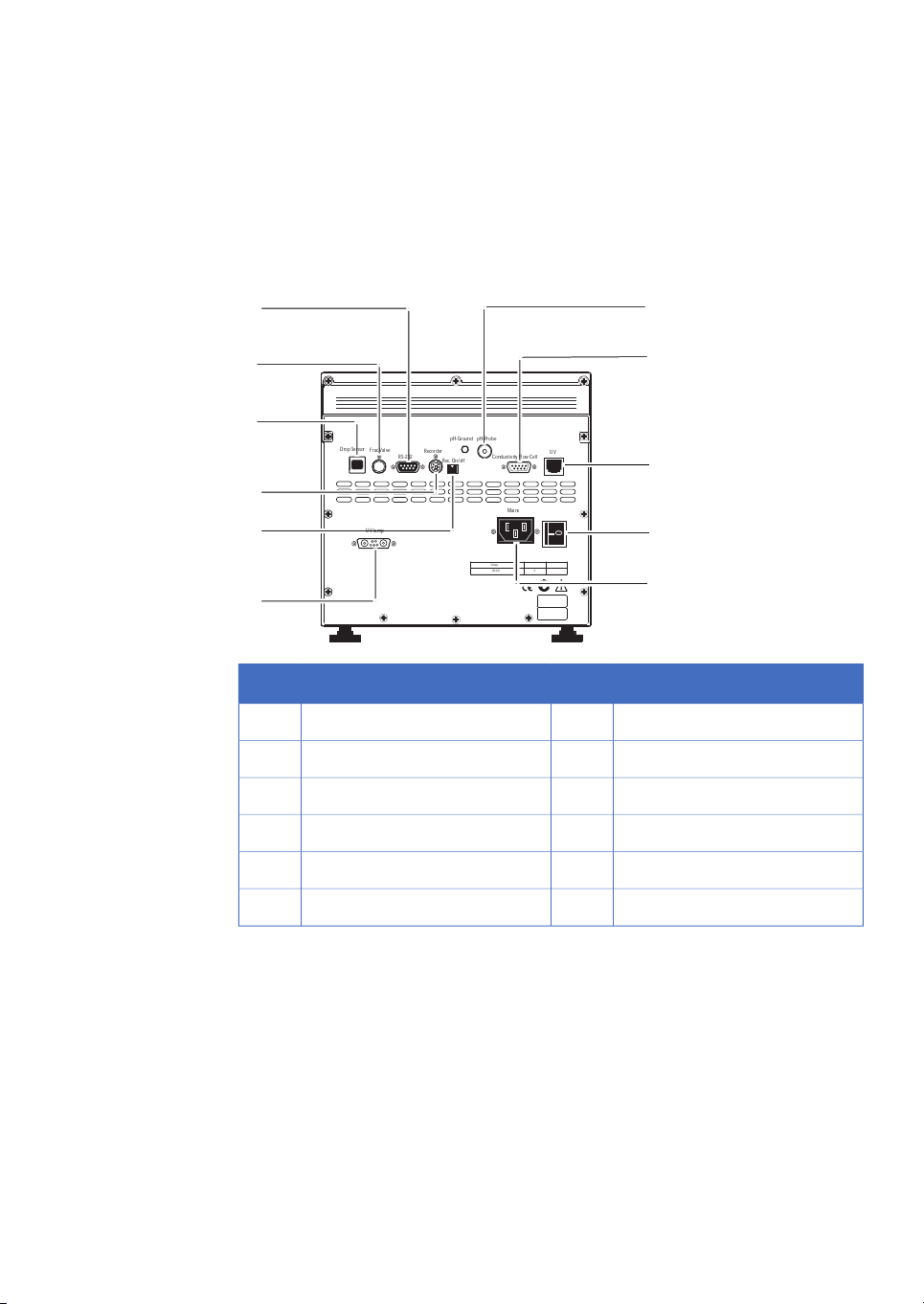
Electrical and communication
connections
1 Introduction
1.3 Instrument
ConnectionNo.ConnectionNo.
pH electrode7RS-232 to computer1
Conductivity flow cell8Flow diversion valve2
Optical unit9Fraction collector3
Power switch10Measurement data to recorder4
Mains power inlet11On/off signals to recorder5
UV lamp6
ÄKTAprime plus Operating Instructions 28-9597-89 AB 11
Page 12
end
OK
Esc
pause
/cont
hold
/cont
feed
tube
1 Introduction
1.3 Instrument
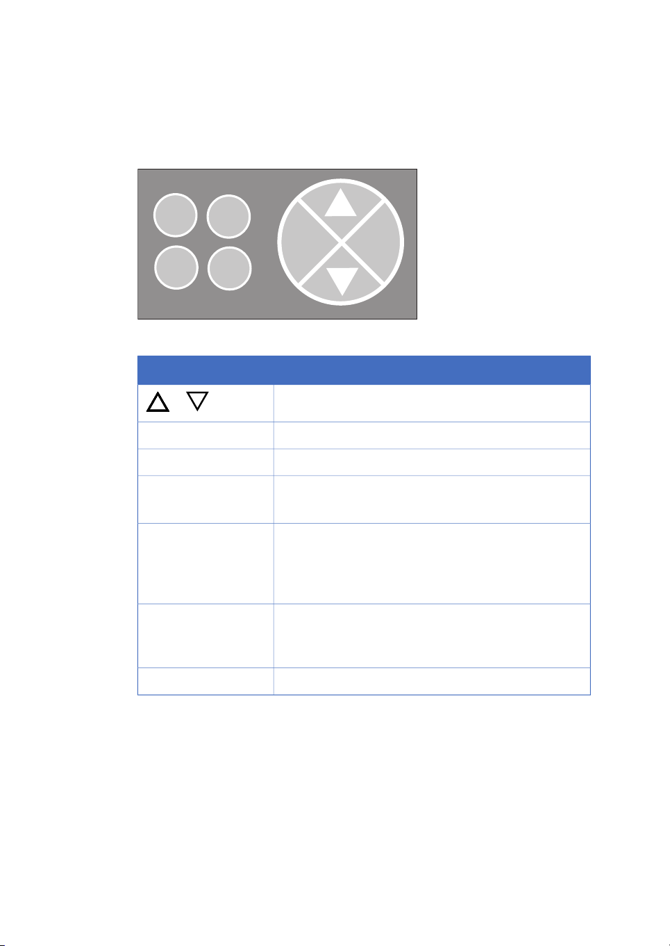
Navigation menu
The system is operated from the push buttons and LCD display at the front panel.
Figure 1.2: Push buttons.
DescriptionButton
or
hold /cont
pause /cont
Find a specific menu option
Enter a menu.OK
Return one menu level.Esc
Interrupt method operation before the run is completed.end
Stop manual operation.
Hold method time or volume and the gradient at the current concentration. Pump and fraction collector continue
uninterrupted.
Continue the normal method operation.
Pause all operation without ending the method. All functions, including pump and fraction collector, are stopped.
Continue the normal method operation.
Advance the fraction collector one position.feed tube
12 ÄKTAprime plus Operating Instructions 28-9597-89 AB
Page 13
Basic flow path
IN
IN
P
M
UV
C
pH
F
W
V2
V1
B
SW
Figure 1.3: Basic flow path.
1 Introduction
1.3 Instrument
DescriptionPartStage
P, V11
Pump P pumps buffer from a buffer container connected to the
buffer valve V1.
SW, B2
To form a gradientthe switch valve (SW)can be usedto pull liquid
from buffer container (B).
The mixer (M) mixes the buffers.M3
V24
Sample is applied from the sample loop connected to injection
valve (V2)that has been previously filledmanually usinga syringe.
UV, C, pH5
From the injection valve, the flow is directed to the column, and
then to the UV, Conductivity, and optional pH monitor.
F, W6
From the monitors, the flow is directed to the Fraction collector
F or the Waste W.
1.4 Monitoring and evaluation
PrimeView™ software
PrimeView isa softwarethat allows real time monitoring,evaluation andreport generation
on an external computer.
For moreinformation aboutPrimeView evaluationsystem and instructionsfor installation,
see the PrimeView User Manual supplied.
ÄKTAprime plus Operating Instructions 28-9597-89 AB 13
Page 14

1 Introduction
1.4 Monitoring and evaluation
Paper chart recorder
It is possible to connect a chart recorder to ÄKTAprime plus to get real time monitoring.
For more information see the ÄKTAprime plus User Manual.
1.5 User documentation
In addition to these Operating Instructions, the documentation package supplied with
ÄKTAprime plus also includes product documentation binders containing detailed
specifications and traceability documents.
The mostimportant documents in the documentpackage withregard totechnical aspects
of ÄKTAprime plus are:
System-specific documentation
ContentUser documentation
ÄKTAprime plus Operating Instructions
ÄKTAprime plus User Manual
ÄKTAprime plus Cue Cards
ÄKTAprime plus training video
EC Declaration of Conformity for
ÄKTAprime plus
All instructionsneeded to operate the instrument in a safe way, including brief
system description, installation, and
maintenance.
Detailed systemdescription. Comprehensive user instructions, method creation,
operation, advanced maintenance and
troubleshooting.
Short step-by-stepinstructions for selected applications using the preprogrammed method templates. System
preparation and value table for the
method templates.
Covers the system introduction, step by
step installation, setting-up the run and
evaluation of results.
Document whereby the manufacturer
ensures that the product satisfies and is
in conformity with the essential requirements of the applicable directives.
14 ÄKTAprime plus Operating Instructions 28-9597-89 AB
Page 15

Software documentation
Together witheach system, the following software documentation is supplied providing
additional information that applies to ÄKTAprime plus, independent of the specific
configuration:
1 Introduction
1.5 User documentation
Purpose/ContentsDocument
PrimeView User Manual
Component documentation
Documentation for components produced both by GE Healthcare and by a third-party
are, if existent, also included in the document package.
A completecontrol software packagefor supervision
of ÄKTAprime plus automated liquid chromatography systems.
ÄKTAprime plus Operating Instructions 28-9597-89 AB 15
Page 16

2 Safety instructions
2 Safety instructions
About this chapter
This chapter describes safety compliance, safety labels, general safety precautions,
emergency procedures, power failure and recycling of ÄKTAprime plus.
2.1 Safety precautions
Introduction
The ÄKTAprime plus instrument is powered by mains voltage and handles pressurized
liquids that may be hazardous. Before installing, operating or maintaining the system,
you must be aware of the hazards described in this manual. Follow the instructions
provided to avoid personal injury or damage to the equipment .
The safety precautions in this section are grouped into the following categories:
•
General precautions
•
Using flammable liquids
•
Personal protection
•
Installing and moving the instrument
•
System operation
•
Maintenance
General precautions
Always follow these General precautions to avoid injury when using the ÄKTAprime plus
instrument.
WARNING
Do not operate ÄKTAprime plus in any other way than described
in the ÄKTAprime plus and PrimeView manuals. If the equipment
is used ina manner not specifiedby the manufacturer,the protection provided by the equipment may be impaired.
16 ÄKTAprime plus Operating Instructions 28-9597-89 AB
Page 17
2 Safety instructions
2.1 Safety precautions
WARNING
Operation anduser maintenanceof the ÄKTAprime plusinstrument
should be performed by properly trained personnel only.
WARNING
Before connecting a column to the ÄKTAprime plus instrument,
read the instructions for use of the column. To avoid exposing the
column to excessive pressure, make sure that the pressure limit is
set to the specified maximum pressure of the column.
WARNING
Do not use any accessories not supplied or recommended by GE
Healthcare.
WARNING
Do not use ÄKTAprime plus if it is not working properly, or if it has
suffered any damage, for example:
•
damage to the power cord or its plug
•
damage caused by dropping the equipment
•
damage caused by splashing liquid onto it
CAUTION
Waste tubesand containers must be secured andsealed to prevent
accidental spillage.
CAUTION
Make sure that the waste container is dimensioned for maximum
possible volume when the instrument is left unattended.
ÄKTAprime plus Operating Instructions 28-9597-89 AB 17
Page 18
2 Safety instructions
2.1 Safety precautions
Using flammable liquids
When usingflammable liquids with theÄKTAprimeplus instrument, followthese precautions to avoid any risk of fire or explosion.
NOTICE
Avoid condensation by letting the unit equilibrate to ambient temperature.
WARNING
Fire Hazard. Before starting the system, make sure that there is
no leakage.
WARNING
A fume hood or similar ventilation system shall be installed when
flammable or noxious substances are used.
Personal protection
WARNING
Always useappropriate PersonalProtective Equipment(PPE) during
operation and maintenance of ÄKTAprime plus system.
WARNING
When using hazardous chemical and biological agents, take all
suitable protective measures, such as wearing protective glasses
and gloves resistant to the substances used. Follow local and/or
national regulations for safe operation and maintenance of
ÄKTAprime plus.
18 ÄKTAprime plus Operating Instructions 28-9597-89 AB
Page 19
Installing and moving the
instrument
2 Safety instructions
2.1 Safety precautions
WARNING
Spread ofbiological agents. Theoperator has to take allnecessary
actions to avoid spreading hazardous biological agents in the
vicinity of the instrument. The facility should comply with the national code of practice for biosafety.
WARNING
High pressure. ÄKTAprime plus operates under high pressure.
Wear protective glasses and other required Personal Protective
Equipment (PPE) at all times.
WARNING
Supply voltage. Make sure that the supply voltage at the wall
outlet corresponds to the marking on the instrument , before connecting the power cord.
WARNING
Protective ground. ÄKTAprime plus must always be connected to
a grounded power outlet.
WARNING
Power cord. Only use power cords with approved plugs delivered
or approved by GE Healthcare.
ÄKTAprime plus Operating Instructions 28-9597-89 AB 19
Page 20
2 Safety instructions
2.1 Safety precautions
WARNING
Access to power switch and power cord with plug. Do not block
access to the power switch and power cord. The power switch
must always be easy to access. The power cord with plug must
always be easy to disconnect.
WARNING
Installing the computer. The computer should be installed and
used according to the instructions provided by the manufacturer
of the computer.
NOTICE
Any computerused withthe equipment shall comply withIEC 60950
and beinstalled and used according tothe manufacturer's instructions.
NOTICE
Disconnect power. Toprevent equipmentdamage, alwaysdiscon-
nect power from the ÄKTAprime plus instrument before an instrument module is removed or installed, or a cable is connected or
disconnected.
System operation
WARNING
Hazardous chemicals during run. When using hazardous chemi-
cals, run System CIP and Column CIP to flush the entire system
tubing with distilled water, before service and maintenance.
20 ÄKTAprime plus Operating Instructions 28-9597-89 AB
Page 21
2 Safety instructions
2.1 Safety precautions
WARNING
Hazardous biological agents during run. When using hazardous
biological agents, run System CIP and Column CIP to flush the
entire system tubing with bacteriostatic solution (e.g. NaOH) followed by a neutral buffer and finally distilled water, before service
and maintenance.
WARNING
There must always be a sample loop connected to ports 2 and 6
of the injection valve. This is to prevent liquid spraying out of the
ports when switching the valve. This is especially dangerous if
hazardous chemicals are used.
CAUTION
Hazardous chemicals in UV flow cell. Make sure that the entire
flow cell has been flushed thoroughly with bacteriostatic solution,
for example NaOH, and distilled water, before service and maintenance.
NOTICE
If the ÄKTAprime plus is kept in acold room, coldcabinet or similar,
keep the system switched on in order to minimize the risk of condensation. (The UV lamp can be turned off to save lamp life time
when the system is not in use.)
NOTICE
When switchingoff the cold cabinet, make surethat youalso switch
off the ÄKTAprime plus system and leave the door to the cold
cabinet open to avoid overheating.
ÄKTAprime plus Operating Instructions 28-9597-89 AB 21
Page 22

2 Safety instructions
2.1 Safety precautions
Maintenance
WARNING
Electrical shock hazard. All repairs should be done by service
personnel authorized by GE Healthcare. Do not open any covers
or replace parts unless specifically stated in the user documentation.
WARNING
Disconnect power.Always disconnect powerfrom the instrument
before replacing any component on the instrument, unless stated
otherwise in the user documentation.
WARNING
Hazardous chemicals during maintenance.When using hazardous
chemicals for system or column cleaning, wash the system or
columns with a neutral solution in the last phase or step.
WARNING
Do not perform any type of maintenance work while the system is
powered electrically or whenthe piping systemis pressurized.Note
that the piping system can be pressurized even when the system
is closed down.
WARNING
Only spare parts and accessories that are approved or supplied
by GE Healthcare may be used for maintaining or servicing
ÄKTAprime plus.
WARNING
Make sure that the piping system is completely leakage free before
performing any CIP on the system.
22 ÄKTAprime plus Operating Instructions 28-9597-89 AB
Page 23

2 Safety instructions
2.1 Safety precautions
WARNING
NaOH is corrosive and therefore dangerous to health. When using
hazardous chemicals, avoid spillage and wear protective glasses
and other suitable Personal Protective Equipment (PPE).
WARNING
After assembly, the piping system must be tested for leakage at
maximum pressure for continued protection against injury risks
due to fluid jets, burst pipes or explosive atmosphere.
WARNING
Before disassembly, check that there is no pressure in the piping
system.
WARNING
Disconnect power.Always disconnect powerfrom the instrument
before replacing fuses.
WARNING
Decontaminate theequipment beforedecommissioning to ensure
that hazardous residues are removed.
CAUTION
Fire hazard. Follow instructions in ÄKTAprime plus Operating
Instructions for correct installation of a new UV-lamp. If the lamp
is not installed properly it may be overheated and cause a fire
hazard.
ÄKTAprime plus Operating Instructions 28-9597-89 AB 23
Page 24

2 Safety instructions
2.1 Safety precautions
2.2 Labels
CAUTION
The systemuses highintensity ultra-violet light. Do not remove the
UV lamp while the system is running. Before replacing a UV lamp,
ensure that the lamp is disconnected to prevent injury to eyes.
If the mercury lamp is broken, make sure that all mercury is removed anddisposed accordingto nationaland local environmental
regulations.
NOTICE
Cleaning. Keep the instrument dry and clean. Wipe regularly with
a softdamp tissue and,if necessary, amild cleaning agent . Let the
instrument dry completely before use.
In this section
This sectiondescribes the instrument labels andlabels concerninghazardous substances
that are attached to the ÄKTAprime plus instrument. For information about marking of
the computer equipment, refer to the manufacturer’s instructions.
Labels on the instrument
The illustration below shows an example of the identification label that is attached to
the ÄKTAprime plus instrument .
24 ÄKTAprime plus Operating Instructions 28-9597-89 AB
Page 25

Symbols used in instrument
labels
MeaningLabel
Warning! Read the user documentation before using the system. Do
not open any covers or replace parts unless specifically stated in the
user documentation.
The systemcomplies withthe requirements for electromagneticcompliance (EMC) in Australia and New Zealand.
The system complies with applicable European directives.
This symbol indicates that ÄKTAprime plus has been certified by a Nationally RecognizedTesting Laboratory(NRTL). NRTLmeans an organization, which is recognized by the US Occupational Safety and Health Administration (OSHA) as meeting the legal requirements of Title 29 of the
Code of Federal Regulations (29 CFR), Part 1910.7.
2 Safety instructions
2.2 Labels
Labels concerning hazardous
substances
MeaningLabel
This symbol indicates that the waste of electrical and electronic equipment must not be disposed as unsorted municipal waste and must be
collected separately.Please contactan authorizedrepresentative of the
manufacturer for information concerning the decommissioning of
equipment.
This symbol indicates that the product contains hazardous materials in
excess ofthe limits established by theChinese standardSJ/T11363-2006
Requirements for Concentration Limitsfor Certain Hazardous Substances
in Electronics.
ÄKTAprime plus Operating Instructions 28-9597-89 AB 25
Page 26

2 Safety instructions
2.3 Emergency procedures
2.3 Emergency procedures
In this section
This sectiondescribes howto doan emergencyshutdown of the ÄKTAprime plussystem.
The section also describes the result in the event of power failure.
Emergency shutdown
In an emergency situation, do as follows to stop the run:
ActionStep
Power failure
1
2
The result of a power failure depends on which unit that is affected.
ÄKTAprime plus
Computer
To pause the runwithout ending the method, pressthe Pausebutton located
at the instrument front.
If required, switch off power to the instrument by pressing the Main power
switch to the 0 position. The run is interrupted immediately.
will result in...Power failure to...
The run is interrupted immediately, in an undefined
•
state
The data collected up to the time of the power failure
•
is available in PrimeView
The PrimeViewcomputer shuts downin an undefined
•
state
The run continues, but data cannot be saved in
•
PrimeView.
26 ÄKTAprime plus Operating Instructions 28-9597-89 AB
Page 27

2.4 Recycling information
Decontamination
ÄKTAprime plus shall be decontaminated before decommissioning and all local regulations shall be followed with regard to scrapping of the equipment .
Disposal, general instructions
When taking ÄKTAprime plus out of service, the different materials must be separated
and recycled according to national and local environmental regulations.
Recycling of hazardous
substances
ÄKTAprime plus contains hazardous substances. Detailed information is available from
your GE Healthcare representative.
2 Safety instructions
2.4 Recycling information
Disposal of electrical
components
Waste ofelectrical and electronic equipment must not bedisposed as unsorted municipal
waste and must be collected separately. Please contact an authorized representative
of the manufacturer for information concerning the decommissioning of equipment.
ÄKTAprime plus Operating Instructions 28-9597-89 AB 27
Page 28

2 Safety instructions
2.5 Declaration of Hazardous Substances (DoHS)
2.5 Declaration of Hazardous Substances (DoHS)
Introduction
The following product pollution controlinformation is providedaccording to SJ/T113642006 Marking for Control of Pollution caused by Electronic Information Products.
根据SJ/T11364-2006《电子信息产品污染控制标识要求》特提供如下有关污染 控制
方面的信息
Symbols used in pollution control
label
电子信息产品污染控制标志说明
MeaningLabel
This symbol indicates the product contains hazardous materials in excess ofthe limits established by theChinese standardSJ/T11363-2006
Requirements for Concentration Limits for Certain Hazardous Substances in Electronic Information Products. The number in the symbol
is theEnvironment-friendly UsePeriod (EFUP), which indicates theperiod
during whichthe toxic or hazardous substances or elementscontained
in electronic information products will not leak or mutateunder normal
operating conditions so that the use of such electronic information
products will not result in any severe environmental pollution, any
bodily injury or damage to any assets. The unit of the period is “Year”.
In order to maintain the declared EFUP, the product shall be operated
normally according to the instructions and environmental conditions
as definedin the product manual, and periodic maintenanceschedules
specified in Product Maintenance Procedures shallbe followed strictly.
Consumables or certain parts may have their own label with an EFUP
value lessthan theproduct. Periodicreplacement ofthose consumables
or parts to maintain the declared EFUP shall be done in accordance
with the Product Maintenance Procedures.
This product must not be disposed of as unsorted municipal waste,
and must be collected separately and handled properly after decommissioning.
28 ÄKTAprime plus Operating Instructions 28-9597-89 AB
Page 29

MeaningLabel
该标志表明本产品含有超过SJ/T11363-2006《电子信息产品中有毒
有害物质的限 量要求》中限量的有毒有害物质。标志中的数字为本
产品的环保使用期,表明本 产品在正常使用的条件下,有毒有害物
质不会发生外泄或突变,用户使用本产品 不会对环境造成严重污染
或对其人身、财产造成严重损害的期限。单位为年。
为保证所申明的环保使用期限,应按产品手册中所规定的环境条件
和方法进行正 常使用,并严格遵守产品维修手册中规定的期维修和
保养要求。
产品中的消耗件和某些零部件可能有其单独的环保使用期限标志,
并且其环保使 用期限有可能比整个产品本身的环保使用期限短。应
到期按产品维修程序更换那 些消耗件和零部件,以保证所申明的整
个产品的环保使用期限。
本产品在使用寿命结束时不可作为普通生活垃圾处理,应被单独收
集妥善处理
List of hazardous substances and
their concentrations
产品中有毒有害物质或元素的名称及含量
2 Safety instructions
2.5 Declaration of Hazardous Substances (DoHS)
Indication for each major part if substance exceeds limit
MeaningValue
O
X
ÄKTAprime plus Operating Instructions 28-9597-89 AB 29
Indicates that this toxic or hazardous substance contained in all of the
homogeneous materials for this part is below the limit requirement in
SJ/T11363-2006.
表示该有毒有害物质在该部件所有均质材料中的含量均在SJ/T113632006 标准规定的限量要 求以下
Indicates that this toxic or hazardous substance contained in at least
one of the homogeneous materials used for this part is above the limit
requirement in SJ/T11363-2006.
Data listed in the table represents best information available at the
•
time of publication
表示该有毒有害物质至少在该部件的某一均质材料中的含量超出
SJ/T11363-2006 标准规定的
限量要求
此表所列数据为发布时所能获得的最佳信息
•
Page 30

2 Safety instructions
2.5 Declaration of Hazardous Substances (DoHS)
List of hazardous substances
Component
name
Hazardous substance
有毒有害物质或元素
部件名称
Pb
铅
Hg
汞
Cd
镉
Cr6+
六价铬
PBB
多溴联苯
PBDE
多溴二苯醚
0000XXÄKTAprime plus
1
1
The product has not been tested as per the Chinese standard SJ/T11363-2006 Requirements
for Concentration Limits for Certain Hazardous Substances in Electronic Information Product.
30 ÄKTAprime plus Operating Instructions 28-9597-89 AB
Page 31

3 Installation
ÄKTAprime plus is delivered in protective packing material and shall be unpacked with
great care.
Any equipment connectedto ÄKTAprime plus must fulfill applicablestandards and local
regulations.
A videodescribing theinstallation process,is suppliedwith each ÄKTAprime plus system.
For detailed information on Installation, see ÄKTAprime plus User Manual.
3.1 Site requirements
3 Installation
RequirementParameter
100-240 V, 50-60 HzElectrical power
4°C to 40°CAmbient temperature
3.2 Transport
The equipment can be transported on a trolley capable of supporting at least 20 kg.
Before moving the system:
•
disconnect all cables and tubing connected to peripheral components and liquid
containers.
•
remove any loose items from the top of the instrument.
•
grasp the instrument firmly by placing the fingers under the base of the main unit
and lift.
For more information on transport, see ÄKTAprime plus User Manual.
Stable laboratory bench e.g. 120 × 80 cmPlacement
20% to 95%, non-condensingHumidity
NOTICE
Lift the instrument in the upright position. Do not use the fractionation arm as a lifting handle.
ÄKTAprime plus Operating Instructions 28-9597-89 AB 31
Page 32

3 Installation
3.3 Unpacking
3.3 Unpacking
Check for damage
Check the equipment for damage before starting assembly and installation. There are
no looseparts inthe transport box. All parts are either mounted on thesystem orlocated
in the accessory kit box. If any damage is found, document the damage, and contact
your local GE Healthcare representative.
Unpack the system
Remove straps and packing material. Then set the equipment upright before starting
installation.
3.4 Connections
Communication
Connect thesystem according to the electricaldrawings in Electrical and communication
connections, on page 11.
Flow path
All parts and tubing are mounted on the system at delivery.
Connect a waste tube, buffer and sample bottles, and optional accessories.
Electrical power
Connect the power cord to a grounded power outlet specified in Section3.1 Site requirements, on page 31.
3.5 Spare parts and accessories
For correct up to date information on spare parts and accessories visit:
www.gelifesciences.com/AKTA
32 ÄKTAprime plus Operating Instructions 28-9597-89 AB
Page 33

4 Operation
About this chapter
This chapter provides instructions for the use of ÄKTAprime plus.
4.1 Operation overview
Workflow
The typical workflow in ÄKTAprime plus, after turning on the system, can be divided into
a number of steps.
4 Operation
SectionActionStep
Section 4.3 Preparations before start, on page 34Prepare the system for a run1
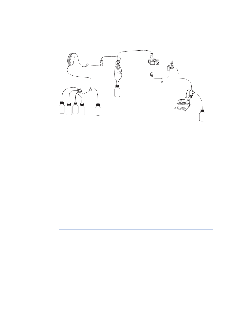
Liquid flow path
See Appendix A Connection diagram - Liquid flow path, on page 65 for an illustration of
the liquid flow path in ÄKTAprime plus.
4.2 Starting the instrument
If the system is not already turned on:
1
Turn on the system using the Power switch at the rear panel. The system now performs a self-test.
2
First thesystem name and software version number aredisplayed. Severalmessages
are then shown during the self-test. If an error is detected during the self-test, an
error message is shown.
3
All parameters are automatically set to factory default values during the self-test.
Section 4.4 Performing a run, on page 39Start a run using a method2
Viewing the run, on page 40During arun -view and changeparameters3
Section 4.5 Procedures after a run, on page 41Procedures after a run4
See PrimeView user documentation.Evaluate the results5
ÄKTAprime plus Operating Instructions 28-9597-89 AB 33
Page 34

4 Operation
4.2 Starting the instrument
4
The self-test takes about 30–40 seconds. When the test is completed, the display
shows the Templates menu.
Note:
The system can be used for most applications after 15 min of lamp warm-up
but the full specifications are not obtained until after 1 hour.
4.3 Preparations before start
Buffer preparation
Prepare buffers according to ÄKTAprime plus cue cards.
Sample preparation
1
Adjust the sample composition to the binding buffer by:
•
diluting the sample in binding buffer, or
•
buffer exchange using HiTrap™ Desalting or HiPrep™ 26/10 Desalting column.
2
Filter the sample through a 0.45 µm filter.
Purification setup
Removing storage solution from the flow path
At delivery and during storage, the flow path is filled with 20% ethanol. This should be
removed before continuing the setup.
Note:
To flush out the ethanol using deionized water:
1
2
3
4
5
34 ÄKTAprime plus Operating Instructions 28-9597-89 AB
Do not use buffer with high salt concentration to flush out the ethanol. It might
cause too high backpressure.
Put the inlet tubing A1–A8 that is used and B in deionized water.
Note:
Put all waste capillaries, W1–W3, in waste.
Select Templates in the main menu using the and buttons and press OK.
Select Application Template and press OK.
Select System Wash Method and press OK.
At delivery, only A1 and B are installed.
Page 35

1
2
3
4
5
6
7
8
9
10
ml
4 Operation
4.3 Preparations before start
6
Choose to wash the A2–A8 inlet tubing that is used by pressing OK at those cursor
positions. A1 and B will always be washed.
Note:
7
Scroll to OK and press the OK button.
8
Press OK to start the method.
9
When the method is finished, replace the first collection tube. It will contain a small
At delivery, only A1 and B are installed.
amount of water after the system wash.
Purging the pump and inlet tubing
If there are large amounts of air in the tubing or if you suspect air in the pump, use the
Purge kit to purge the flow path. Air bubbles that still are trapped in the pump (causing
increased pulsation) can beremoved by flushing 100% ethanolthrough thepump. These
two procedures are described in the following two sections.
Purging the flow path using the Purge kit:
1
Remove the stop plug from the pump.
2
Connect the Purge kit to the pump.
3
Put the used inlet tubing in the appropriate buffers.
4
Run the pump at 0.1 ml/min.
Filling inlet tubing A1–A8:
1
Go to Set Buffer Valve using the arrow buttons.
2
Set the chosen A inlet and press OK. The valve switches to the selected port.
3
Draw buffer with the purge syringe until liquid enters the syringe.
4
Repeat step 1–3 until all chosen A inlet tubing is filled.
Filling inlet tubing B:
ÄKTAprime plus Operating Instructions 28-9597-89 AB 35
1
Go to Set Concentration %B and set the concentration to 100%.
Page 36

1
2
3
4
4 Operation
4.3 Preparations before start
2
Press OK. The switch valve turns to the inlet B port.
3
Draw buffer with the purge syringe until liquid enters the syringe.
4
Replace the purge tubing with the stop plug.
5
Stop the pump by pressing end and then OK.
Flushing the pump with 100% ethanol:
1
Put inlet tubing A1 in deionized water.
2
Run the pump at 40 ml/min for 1 min and press pause/cont.
3
Move inlet tubing A1 to 100% ethanol
4
Press pause/cont, run the pump for 10–20 s and press pause/cont.
5
Set the flow rate to 5 ml/min using the arrow buttons.
6
Press pause/cont, run the pump for at least 30 s and press pause/cont.
7
Move inlet tubing A1 to deionized water.
8
Press pause/cont and run the pump for 1 min.
9
Finish by pressing end and then OK.
Preparing the tubing and column
1
Put inlet tubing A1 in the binding buffer.
2
Put inlet tubing B in the elution buffer.
3
Put the threewaste capillaries (brown color)from port 4 and 5 on the injection valve
and port NO on the fraction collector valve in waste.
4
Connect a column, for example a HisTrap™ HP 1 ml column, between port 1 on the
injection valve and the upper port of the UV flow cell. Use a suitable length of PEEK
tubing and 1/16" male connectors.
36 ÄKTAprime plus Operating Instructions 28-9597-89 AB
Page 37

5 mm
1
2
5.
3.
4.
1.
2.
4 Operation
4.3 Preparations before start
DescriptionNo.DescriptionNo.
HisTrap column3Tubing from injection valve1
UV cell41/16" male connector2
Note:
Other unions and connectors might be required for other columns.
Preparing the fraction collector
1
Fill the fraction collector rack with, for example, 18 mm tubes (minimum 40 pcs.).
2
Adjust the height of the delivery arm using the lock knob (1) so that the bottom of
the tubesensor (2) is about 5mm below thetop of the tubes. Thetubes should always
be below the horizontal mark on the tube sensor.
3
If necessary, adjust the length of the tubing exposed according to the sequence
shown below (the hole in the delivery arm used in step 3 and 4 is only used for adjusting the tubing length).
ÄKTAprime plus Operating Instructions 28-9597-89 AB 37
Page 38

2
1
3
4 Operation
4.3 Preparations before start
4
Check that the tube sensor (1) is in the correct position for the tube size. The eluent
tubing should be over the center of the collection tube. Use the red sensor control
knob (2) to position the tube holder (3).
5
Rotate the rack by hand until the rear half of the tube sensor rests against the first
tube.
6
Press feed tube on the front panel (see Figure 1.2). The bowl moves to the correct
position to collect the first fraction in the first tube.
7
Make sure that drop synchronization is turned on.
Note:
Drop synchronization can NOT be used at flowrates above 3 ml/min.
Preparing the monitors
1
Check the UV lamp filter position and the lamp position.
2
Calibrate the pH electrode (optional).
See ÄKTAprime plus User Manual for more information.
Filling the buffer inlet tubing
When running an application templates, the buffer inlet tubing will automatically be
filled with buffer.
For other applications, fill the inlet tubing manually with buffer as described in the
ÄKTAprime plus User Manual.
Filling the sample loop
Using an injection fill port
38 ÄKTAprime plus Operating Instructions 28-9597-89 AB
Page 39

3
1
4 Operation
4.3 Preparations before start
1
Connect a sample loop between port 2 and 6 on the injection valve. Make sure that
the sample loop is large enough for your sample.
2
Connect a luer female/1/16" male union to port 3.
3
Fill a syringe with five loop volumes of deionized water or binding buffer.
4
Fit the syringe in the Luer union (1) and carefully inject the buffer.
5
Remove the syringe and fill it with at least two loop volumes of the sample.
6
Carefully inject the sample into the sample loop. Do NOT remove the syringe after
the injection because the loop might otherwise be emptied due to self-drainage or
air may be introduced in the flow path.
4.4 Performing a run
Selecting template and starting
the run
1
Select Templates in the main menu and press OK.
2
Select Application Template and press OK.
3
Select theappropriate template,for example His Tag Purification HisTrap, and press
OK.
4
Set the sample volume and press OK.
5
Press OK to start the purification run.
ÄKTAprime plus Operating Instructions 28-9597-89 AB 39
Page 40

4 Operation
4.4 Performing a run
Viewing the run
When the pump starts running, the progress of the run can be viewed in the two panes
in PrimeView.
•
The Curves pane displays monitor signal values graphically.
•
The Logbook pane displays all actions (e.g. method start and end, base instructions
and methodinstructions) andunexpected conditions(e.g. warningsand alarms).The
log is saved in the result file.
Selecting curves to be displayed
1
In PrimeView module, select View:Properties.
2
In the Properties dialog, click the Curves tab.
3
In the Display curves list, select the curves you want to display.
4
Click OK.
For more information on customizing the view panes, see PrimeView User Manual.
40 ÄKTAprime plus Operating Instructions 28-9597-89 AB
Page 41

Ending the run
Press OK at the Method Complete prompt. This will cause all valves to return to their
default positions.
To stop the run on a system before it is finished:
1
Press the end button.
2
Select yes and press OK.
Error indication
When a warning or an alarm is issued from a system, an error code is displayed. See
ÄKTAprime plus User Manual for guidance.
Evaluate the results
PrimeView Evaluation module provides facilities for the presentation and evaluation of
separation results.
To start PrimeViewEvaluation module, click PrimeView Evaluationicon on the Windows
desktop.
4 Operation
4.4 Performing a run
See ÄKTAprime plus User Manual and PrimeView User Manual for how to evaluate the
results.
4.5 Procedures after a run
Cleaning after a run
NOTICE
Do not allow solutions which contain dissolved salts, proteins or
other solid solutes to dry out in the UV flow cell.
ÄKTAprime plus Operating Instructions 28-9597-89 AB 41
Page 42

4 Operation
4.5 Procedures after a run
Buffers notcontaining any saltcan be left in the system for ashort time aftera run, even
overnight (not in the pH electrode, see instructions below).
To flush the flow path:
1
Fill a syringe with five times the sample loop volume of deionized water.
2
Rinse the sample loop by injecting the water through the fill port on the injection
valve.
3
Put all used inlet tubings in water.
4
In theTemplates menu,select Application Template and thenSystem Wash Method.
5
Select the used inlet ports. Inlets A1 and B will always be washed.
6
Press OK to start the method. The system flow path is now automatically flushed.
For informationon cleaning andlong-term storage, see Section 5.3 Cleaning, on page46
and Section 5.7 Storage, on page 49.
NOTICE
Do not allow particles to enter the UV flow cell as damage to the
flow cell might occur.
NOTICE
If a buffer containing salt has been used, the flow path must be
flushed with deionized water.
42 ÄKTAprime plus Operating Instructions 28-9597-89 AB
Page 43

5 Maintenance
About this chapter
This chapter provides instructions for routine component maintenance and a maintenance schedule.
5.1 General
Regular maintenanceis important for safe andtrouble-free operationof your instrument.
The usershould perform daily and monthlymaintenance. Preventive maintenanceshould
be performed on a yearly basis by qualified service personnel.
For maintenance of a specific component, carefully read the component manual and
follow the instructions.
WARNING
Electrical shock hazard. All repairs should be done by service
personnel authorized by GE Healthcare. Do not open any covers
or replace parts unless specifically stated in the user documentation.
5 Maintenance
WARNING
Disconnect power.Always disconnect powerfrom the instrument
before replacing any component on the instrument, unless stated
otherwise in the user documentation.
WARNING
Hazardous chemicals during maintenance.When using hazardous
chemicals for system or column cleaning, wash the system or
columns with a neutral solution in the last phase or step.
ÄKTAprime plus Operating Instructions 28-9597-89 AB 43
Page 44

5 Maintenance
5.1 General
WARNING
Do not perform any type of maintenance work while the system is
powered electrically or whenthe piping systemis pressurized.Note
that the piping system can be pressurized even when the system
is closed down.
WARNING
When using hazardous chemical and biological agents, take all
suitable protective measures, such as wearing protective glasses
and gloves resistant to the substances used. Follow local and/or
national regulations for safe operation and maintenance of
ÄKTAprime plus.
CAUTION
Fire hazard. Follow instructions in ÄKTAprime plus Operating
Instructions for correct installation of a new UV-lamp. If the lamp
is not installed properly it may be overheated and cause a fire
hazard.
NOTICE
Cleaning. Keep the instrument dry and clean. Wipe regularly with
a softdamp tissue and,if necessary, amild cleaning agent . Let the
instrument dry completely before use.
5.2 User maintenance schedule
Table 5.1 provides a guide to maintenance operations and intervals at which these operations should be performed by the user. The user is however responsible for deciding
the type of operations and length of intervals necessary to maintain system function
and safety.
44 ÄKTAprime plus Operating Instructions 28-9597-89 AB
Page 45

Table 5.1: User maintenance schedule
5 Maintenance
5.2 User maintenance schedule
Instructions/referenceActionInterval
Visually inspect the system for leaks.Leak inspectionDaily
Wash thesystem flow
path
Calibrate pHelectrode
(optional)
Check inlet filtersWeekly
(if applicable)
Flow restrictorMonthly
For cleaningthe flowpath, seeCleaning-In-
1
Place, on page 46.
For leaving the system for a few days, see
2
Section 5.7 Storage, on page 49.
Calibrate thepH electrode(if applicable) according to Monitor pH/C-900 User Manual.
Check theinlet filters visually and replace them
if necessary.
Replace the on-line filter.Replace on-line filter
Check thatflow restrictor generates the following back-pressure:
FR-904: 0.4 ±0.05 MPa
Check the back-pressure as follows:
Disconnect the flow restrictor.
1
Connect a tubing (approx. 1 m, i.d. 1 mm)
2
to the waste port (port 5) on the injection
valve. Set the injection valve manually to
Waste position.Put the open end ina waste
container.
Run the pump manually at 10 ml/min with
3
water. Note the back-pressure (Bp1) on the
pump display, or in the Run Data window.
Set the system to Pause and connect the
4
flow restrictor to the openend ofthe tubing
(observe theIN marking). Putthe flow restrictor in the waste container.
Press Continue so that the pump run at 10
5
ml/min with water. Note the back-pressure
(Bp2) on the pump display, or in the Run
Data window.
Calculate the back-pressure generated by
6
the flow restrictor (Bp2-Bp1). Replace it if it
is not within limit.
ÄKTAprime plus Operating Instructions 28-9597-89 AB 45
Page 46

5 Maintenance
5.2 User maintenance schedule
Instructions/referenceActionInterval
5.3 Cleaning
Cleaning before planned
maintenance/service
To ensure the protection and safety of service personnel, all equipmentand work areas
must beclean and freeof any hazardous contaminantsbefore a Service Engineerstarts
maintenance work.
Please complete the checklist in the On Site Service Health & Safety Declaration Form or
the Health & Safety Declaration Form for Product Return or Servicing, depending on
whether theinstrument is goingto be serviced on site or returned forservice, respectively.
Copy theform you need from Section7.4 Health and Safety Declaration Form, on page 62
or print it from the PDF file available on the User Documentation CD.
Cleaning-In-Place
All components in the system are designed for ease of CIP.
After repeated separation cycles, contaminating material might progressively build up
in the system and on the column. This material may not have been removed by the
cleaning step described above. The nature and degree of contamination depends on
the sampleand the chromatographic conditions employed.These should be considered
when designing a cleaning protocol.
Routine cleaning should be performed at intervals aimed at prevention rather than
cleaning the system from growth or contamination.
Valve inspectionYearly
Check for external or internal leakage. Replace
channel plate and distribution plate yearly or
when required. Refer to the relevant valve instruction sheet.
WARNING
Make sure that the piping system is completely leakage free before
performing any CIP on the system.
46 ÄKTAprime plus Operating Instructions 28-9597-89 AB
Page 47

5 Maintenance
5.3 Cleaning
Make sure that the process control method for cleaning flushes all possible flow paths
in the system. After cleaning, rinse the entire system with water or suitable liquid until
the piping/tubingsystem iscompletely freefrom theCIP solution(monitors inthe system
can be used as detectors). Do not leave NaOH or other cleaning agents in the system
for long periods.
WARNING
Hazardous chemicals during maintenance.When using hazardous
chemicals for system or column cleaning, wash the system or
columns with a neutral solution in the last phase or step.
WARNING
NaOH is corrosive and therefore dangerous to health. When using
hazardous chemicals, avoid spillage and wear protective glasses
and other suitable Personal Protective Equipment (PPE).
See also Section 5.7 Storage, on page 49.
5.4 Component maintenance
Maintenance andpreventive replacement ofparts of the major componentsare described
in the respective manuals included in the system documentation.
The system documentation also includes a spare part list to be used to find common
spare parts and their code numbers for ordering. This list can also be found online at
www.gelifesciences.com/AKTA.
5.5 Disassembly and assembly of components and consumables
The operator must carefully read and understand the instructions supplied for each
component before disassembly and assembly of the component. When replacing consumables, suchas tubing and tubing connectors,all neccessary safety precautions must
be taken. Contact your local GE Healthcare representative if further information or help
is needed.
WARNING
Disconnect power.Always disconnect powerfrom the instrument
before replacing any component on the instrument, unless stated
otherwise in the user documentation.
ÄKTAprime plus Operating Instructions 28-9597-89 AB 47
Page 48

5 Maintenance
5.5 Disassembly and assembly of components and consumables
WARNING
Before disassembly, check that there is no pressure in the piping
system.
WARNING
After assembly, the piping system must be tested for leakage at
maximum pressure for continued protection against injury risks
due to fluid jets, burst pipes or explosive atmosphere.
5.6 Calibration
The table below lists the type and frequency of calibrations that can be done on the instrument. Refer toPrimeView user documentation and tothe individual component User
Manuals and Instructions for descriptions of how to perform these calibrations. The
calibrations are performed from PrimeView by selecting System:Calibrate in System
Control.
flow cell
Cell constantConductivity
Temperature
Entering a
new cell constant
How oftenComponent
Every day.pH monitor (if applicable)
When required.Pump (if applicable)
When required.Pressure reading
Only necessary if specific conductivity with high
accuracy is measured (Cond_Calib).
Must be done when changing the conductivity
flow cell (Temp).
Must be done when changing the conductivity
flow cell (Cond_Cell).
48 ÄKTAprime plus Operating Instructions 28-9597-89 AB
Page 49

5.7 Storage
General recommendation
For storage, the system must first be cleaned as described in Cleaning-In-Place, on
page 46. After cleaning, the system must be filled with 0.01 M NaOH or 20% ethanol
solution.
Columns and media shall be stored according to their respective instructions.
Storage conditions
The following conditions shall be maintained while the system is in storage:
•
Temperature: 2°C to 30°C (preferably room temperature)
•
Relative humidity: 0% to 95%, non-condensing (preferably low humidity).
After storage,clean the system, calibrate allmonitors, and performa leakage testbefore
using the system.
5 Maintenance
5.7 Storage
ÄKTAprime plus Operating Instructions 28-9597-89 AB 49
Page 50

6 Troubleshooting
6 Troubleshooting
6.1 UV curve problems
Corrective actionPossible causeError symptom
Ghost peak
nal drift or instability
Dirt or residues in the
flow path from previous runs. Air in the
eluents.
Residue inthe column
from previous runs
Incorrect mixer function
Dirty UV cellNoisy UV-signal, sig-
Impure buffer
Air in the pump or in
the UV cell
Clean the system. Make sure air is
removed.
Clean thecolumn according to the
column instructions.
Check the mixer function by placing astirrer baron top of the mixer
housing. The stirrer bar should rotate when the system is in Run
mode. Themixer function can also
be checkedby running the installation test.
Clean the UV cell by flushing
Decon™ 90, Deconex™ 11 or
equivalent.
Check ifthe signalis still noisy with
water.
Purge the pump according to
Pump User Manual. Run a system
wash with buffer.
50 ÄKTAprime plus Operating Instructions 28-9597-89 AB
Page 51

6 Troubleshooting
6.1 UV curve problems
Corrective actionPossible causeError symptom
Aging UV lampLow sensitivity
UV lamp in wrong position
The theoreticalextinction coefficient too
low
6.2 Conductivity curve problems
Baseline drift or noisy
signal
Air in the pump or the
flow cell
Leaking tubeconnections
Incorrect mixer function
Check thelamp runtime according
to and replace if necessary. Refer
to ÄKTAprime plus User Manual.
Check that the lamp position and
the filter position are both set to
the wavelength tobe used, 280 nm
or 254nm. Refer to ÄKTAprimeplus
User Manual.
Calculate thetheoretical extinction
coefficient of the protein. If it is zero or very low at 280 nm, the protein cannot be detected.
Corrective actionPossible causeError symptom
Check the flow restrictor after the
flow cell.
Tighten the clamps. If necessary,
replace the clamps.
Check the mixer function by placing astirrer baron top of the mixer
housing. The stirrer bar should rotate when the system is in Run
mode. Themixer function can also
be checkedby running the installation test.
Dirty conductivity cell
Column notequilibrated
Dirty flow cellConductivity measurement with the same
buffer appears to decrease over time
ÄKTAprime plus Operating Instructions 28-9597-89 AB 51
Decrease in ambient
temperature
Clean the conductivity cell by
flushing 1M NaOH or 20% ethanol.
Equilibrate the column. If necessary, clean the column using a
method plan for column cleaning.
Clean the flow cell according to
procedure in Monitor User Manual.
Use a temperature compensation
factor. See Monitor User Manual.
Page 52

6 Troubleshooting
6.2 Conductivity curve problems
Corrective actionPossible causeError symptom
Waves on the gradient
in the gradient profile
slow response to %B
changes
Incorrect pump function
Dirty mixing chamber
Insufficient mixing
chamber volume
Incorrect motor function
Air in the flow cellGhost peaks appear
Dirty tubingUnlinear gradients or
ume
Check that the pump is operating
and is programmed correctly.
Check that the mixing chamber is
free from dirt or particles.
Change to a larger mixing chamber volume if necessary.
Check the motor operation. Place
a hand on the mixer and start it by
starting the pump at a low flow
rate. You shouldboth hear and feel
the mixer motor and stirrer when
they are spinning.
Check for loose tubing connections. Use the flow restrictor.
Wash the tubing and check pump
is operating properly.
Change to smaller mixer volume.Incorrect mixer vol-
52 ÄKTAprime plus Operating Instructions 28-9597-89 AB
Page 53

6 Troubleshooting
6.2 Conductivity curve problems
Corrective actionPossible causeError symptom
Incorrect or unstable
reading
6.3 pH curve problems
Loose connection of
conductivity flow ca-
ble
Incorrect pump and
valves function
Incorrect temperature
compensation factor
Dirty or incorrectly
equilibrated column
Incorrect mixer func-
tion
Check that the conductivity flow
cell cable is connected properly.
Check that the pump and valves
operate correctly.
If temperature compensation is
being used,check thatthe temperature sensoris calibrated, and that
the correct temperature compensation factor is in use.
Check thatthe columnis equilibrated. If necessary clean the column.
Check the operation of the mixer.
The mixer function is checked by
placing a stirrer bar on top of the
mixer housing. The stirrer bar
should rotate when the system is
in Run mode. The mixer function
can also be checked by running
the installation test.
Corrective actionPossible causeError symptom
No response to pH
changes
changes
ÄKTAprime plus Operating Instructions 28-9597-89 AB 53
Faulty electrode con-
nection
Damaged electrode
Incorrectly connected
pH monitor
Dirty pH electrodeSmall response to pH
Check that the electrode cable is
connected properly.
The electrode glass membrane
may becracked. Replace the electrode.
Check that the pH monitor is correctly connected according to the
ÄKTAprime plus User Manual.
Clean thepH electrode as detailed
in Monitor pH/C-900 User Manual.
If theproblem remains,replace the
pH electrode.
Page 54

6 Troubleshooting
6.3 pH curve problems
Corrective actionPossible causeError symptom
Slow pH response or
Calibration impossible
Contaminated electrode glass membrane
Membrane has dried
out
Check the electrode glass membrane. If it is contaminated, clean
the electrodefollowing theinstructions in Monitor pH/C-900 User
Manual.
If themembrane has dried out, the
electrode may be restored by
soaking it in buffer overnight.
54 ÄKTAprime plus Operating Instructions 28-9597-89 AB
Page 55

6 Troubleshooting
6.3 pH curve problems
Corrective actionPossible causeError symptom
Incorrect or unstable
pH reading
Problem with elec-
trode
Check that the electrode cable is
connected properly.
Check thatthe electrodeis correctly inserted in the flow cell and, if
necessary, hand-tighten the nut.
Check that the pH electrode is not
broken.
Calibrate the pH electrode.
Clean the pH electrode if required,
see MonitorpH/C-900 User Manual.
Compare the response of the pH
electrode with that of another pH
electrode. If the response differ
greatly, the electrode may require
cleaning or replacement.
In organic solvents such as
ethanol, methanoland acetonitrile,
stable pH measurements are not
possible since dehydration of the
membrane will occur. It is recommended that the pH electrode is
not used in applications using organic solvents. Mount the dummy
electrode instead.
Incorrect pump or
valve operation
Air in the flow cell
Check that the pump and valves
operate correctly.
If air in the flow cell is suspected,
tap the flow cell carefully or tilt it
to remove the air. Alternatively,
flush the cell with buffer at 20
ml/min (E100 system)or 10 ml/min
(E 10 system) for 1/2 min. Use the
flow restrictor FR-902 after the pH
electrode.
Static interference
There may be interference from
static fields. Connect the pH flow
cell and the rear panel of the
monitor usinga standardlaboratory 4 mm “banana plug” cable.
ÄKTAprime plus Operating Instructions 28-9597-89 AB 55
Page 56

6 Troubleshooting
6.3 pH curve problems
Corrective actionPossible causeError symptom
pH values vary with
varied back pressure
electrode
6.4 Pressure curve problems
Erratic flow, noisy
baseline signal,irregular pressure trace
through or trapped in
the pump
Inlet or outlet check
valves notfunctioning
correctly
Piston seal leaking
Replace the pH electrode.Problem with the
Corrective actionPossible causeError symptom
Check all connections for leaks.Air bubbles passing
Check thatthere is sufficient eluent
present in the reservoirs.
Use degassed solutions.
Purge the pump.
Follow the instructions in
ÄKTAprime plus User Manual.
Clean the valves according to
Pump P-920 User Manual.
Clean the valves according to
ÄKTAprime plus User Manual.
Replace the piston seal according
to the instructions in .ÄKTAprime
plus User Manual.
Flush through to clear blockage.Blockage or part
blockage of flowpath
56 ÄKTAprime plus Operating Instructions 28-9597-89 AB
If necessary, replace tubing.
Check inlet tubing filter. It can become clogged if unfiltered buffers
or samplesare applied.See instructions for flushing through at the
end of the run in ÄKTAprime plus
User Manual.
Page 57

7 Reference information
About this chapter
This chapter contains technical data, regulatory and other information.
7.1 Specifications
ValueParameter
Housing: IP20Ingression protection
Flow cells: IP44
100-120/220-240 V ~, 50 to 60 HzSupply voltage
90 VAPower consumption
T 1.0 AH 250 VFuse specification
7 Reference information
7.2 Chemical resistance
Chemical
Exposure
< 1 day
up to 2
months
OKOKAcetaldehyde
OKOKAcetic acid, < 5%
530 × 400 × 450 mmDimensions (H × W × D)
13 kgWeight
4°C to 40°CAmbient temperature
10% to 95%Relative humidity tolerance (non-condensing)
84 to 106 kPa (840 to 1060 mbar)Atmospheric pressure
CommentsEEC no.CAS no.Exposure
200-580-764-19-7OKOKAcetic acid, 70%
200-835-275-05-8OKOKAcetonitrile
FFKM, PP and PE
swell.
ÄKTAprime plus Operating Instructions 28-9597-89 AB 57
Page 58

7 Reference information
7.2 Chemical resistance
Chemical
ride
bonate
phate
Exposure
< 1 day
up to 2
months
AvoidOKAcetone, 10%
OKOKAmmonium bicar-
OKOKAmmonium nitrate
OKOK1-Butanol
OKOK2-Butanol
AvoidOKChloroform
CommentsEEC no.CAS no.Exposure
PVDF is affected by
long term use.
231-635-37664-41-7OKOKAmmonia, 30%
Silicone is affected
by long-term use.
235-186-412125-02-9OKOKAmmonium chlo-
231-984-17783-20-2OKOKAmmonium sul-
249-576-729340-81-6OKOKCitric acid
Kalrez™, CTFE, PP
and PE are affected
by long term use.
OKOKCyclohexane
OKOKDetergents
200-664-367-68-5AvoidAvoidDimethyl sulphox-
ide
AvoidAvoid1, 4-Dioxane
PVDF is affected by
long term use.
ETFE, PP, PE and
PVDF are affected
by long term use.
200-837-375-08-1OKOKEthanol, 100%
AvoidOKEthyl acetate
Silicone not resistant. Pressure limit
for PEEKdecreases.
203-473-3107-21-1OKOKEthylene glycol,
100%
58 ÄKTAprime plus Operating Instructions 28-9597-89 AB
Page 59

7 Reference information
7.2 Chemical resistance
Chemical
drochloride
0.1 M
> 0.1 M
Exposure
< 1 day
up to 2
months
OKOKGuanidinium hy-
AvoidOKHexane
AvoidOKHydrochloric acid,
CommentsEEC no.CAS no.Exposure
200-579-164-18-6OKOKFormic acid, 100%
Silicone not resistant.
200-289-556-81-5OKOKGlycerol, 100%
Silicone not resistant. Pressure limit
for PEEKdecreases.
231-595-77647-01-0OKOKHydrochloric acid,
Silicone not resistant.
Silicone not resistant. Titanium isaffected bylong term
use.
200-661-767-63-0OKOKIsopropanol, 100%
200-659-674-93-1OKOKMethanol, 100%
AvoidOKNitric acid, diluted
Silicone not resistant.
AvoidAvoidNitric acid, 30%
Elgiloy™ is affected
by long term use.
231-633-27664-38-2AvoidOKPhosphoric acid,
10%
Titanium, aluminium oxide and glass
are affected by
long term use.
209-529-3584-08-7OKOKPotassium carbon-
ate
231-211-87447-40-7OKOKPotassium chloride
AvoidAvoidPyridine
ETFE, PP and PE not
resistant.
OKOKSodium acetate
ÄKTAprime plus Operating Instructions 28-9597-89 AB 59
Page 60

7 Reference information
7.2 Chemical resistance
Chemical
ate
2 M
ed
medium concentration
Exposure
< 1 day
up to 2
months
OKOKSodium bicarbon-
OKOKSodium bisulphate
OKOKSodium borate
OKOKSodium carbonate
AvoidOKSulphuric acid, dilut-
AvoidAvoidSulphuric acid,
CommentsEEC no.CAS no.Exposure
231-598-37647-14-5OKOKSodium chloride
215-185-51310-73-2AvoidOKSodium hydroxide,
PVDF and borosilicate glass are affected bylong term
use.
231-820-97757-82-6OKOKSodium sulphate
PEEK and titanium
are affected by
long term use.
AvoidAvoidTetrachloroethy-
lene
AvoidAvoidTetrahydrofuran
Silicone, PP and PE
are not resistant.
ETFE, CTFE, PP and
PE arenot resistant.
AvoidOKToluene
Pressure limit for
PEEK decreases.
200-927-276-03-9OKOKTrichloroacetic
acid, 1%
200-929-3176-05-1OKOKTrifluoroaceticacid,
1%
200-315-557-13-6OKOKUrea, 8M
AvoidOKo-Xylene and p-Xy-
lene
PP and PE are affected bylong term
use.
60 ÄKTAprime plus Operating Instructions 28-9597-89 AB
Page 61

7.3 System recommendations
Refer to ÄKTAprime plusUser Manual, or contact your local GE Healthcarerepresentative
for the most current information.
7 Reference information
7.3 System recommendations
ÄKTAprime plus Operating Instructions 28-9597-89 AB 61
Page 62

GE Services On Site Service Health &
Safety Declaration Form
Service Ticket #:
To ensure the mutual protection and safety of GE Healthcare service personnel and our customers, all equipment and work
areas must be clean and free of any hazardous contaminants before a Service Engineer starts a repair. To avoid delays in the
servicing of your equipment, please complete this checklist and present it to the Service Engineer upon arrival. Equipment and/
or work areas not sufficiently cleaned, accessible and safe for an engineer may lead to delays in servicing the equipment and
could be subject to additional charges.
Yes No
Please review the actions below and answer “Yes” or “No”. Provide explanation for any “No” answers
in box below.
Instrument has been cleaned of hazardous substances.
Please rinse tubing or piping, wipe down scanner surfaces, or otherwise ensure removal of any dangerous
residue. Ensure the area around the instrument is clean. If radioactivity has been used, please perform a
wipe test or other suitable survey.
Adequate space and clearance is provided to allow safe access for instrument service, repair
or installation.
In some cases this may require customer to move equipment from normal operating location prior
to GE arrival.
Consumables, such as columns or gels, have been removed or isolated from the instrument and from
any area that may impede access to the instrument.
All buffer / waste vessels are labeled. Excess containers have been removed from the area to
provide access.
Provide
explanation
for any “No”
answers here:
Equipment type / Product No: Serial No:
I hereby confirm that the equipment specified above has been cleaned to remove any hazardous substances and that the area
has been made safe and accessible.
Name in Capital letters:
Company or institution:
Position or job title: Date (Year/month/date): 200000/00000/00000
GE, imagination at work and GE monogram are trademarks of General Electric Company.
GE Healthcare Bio-Sciences Corp, 800 Centennial Avenue, P.O. Box 1327, Piscataway,
NJ 08855-1327, USA.
© 2010-12 General Electric Company—All rights reserved. First published April 2010.
28-9800-26 AB 05/2012
Signed:
DOC1149542
7 Reference information
7.4 Health and Safety Declaration Form
7.4 Health and Safety Declaration Form
On site service
62 ÄKTAprime plus Operating Instructions 28-9597-89 AB
Page 63

GE Services
Health & Safety Declaration Form
for Product Return or Servicing
DOC1149544
To ensure the mutual protection and safety of GE Healthcare personnel, our customers, transportation personnel and our
environment, all equipment must be clean and free of any hazardous contaminants before shipping to GE Healthcare. To avoid
delays in the processing of your equipment, please complete this checklist and include it with your return.
1. Please note that items will NOT be accepted for servicing or return without this form
2. Equipment which is not sufficiently cleaned prior to return to GE Healthcare may lead to delays in servicing the equipment
and could be subject to additional charges
3. Visible contamination will be assumed hazardous and additional cleaning and decontamination charges will be applied
Equipment type / Product No: Serial No:
I hereby confirm that the equipment specified above has been cleaned to remove any hazardous substances and that the area
has been made safe and accessible.
Name in Capital letters:
Company or institution:
Position or job title: Date (Year/month/date): 200000/00000/00000
GE, imagination at work and GE monogram are trademarks of General Electric Company.
GE Healthcare Bio-Sciences Corp, 800 Centennial Avenue, P.O. Box 1327, Piscataway,
NJ 08855-1327, USA.
© 2010-12 General Electric Company—All rights reserved. First published April 2010.
28-9800-27 AB 05/2012
Return authorization number: and/or Service Ticket/Request:
To receive a return authorization number or service
number, please call local technical support or
customer service.
Please specify if the equipment has been in contact with any of the following:
Yes No Radioactivity (please specify):
Yes No Infectious or hazardous biological substances (please specify)
Yes No Other Hazardous Chemicals (please specify)
Equipment must be decontaminated prior to service / return. Please provide a telephone number where GE Healthcare can
contact you for additional information concerning the system / equipment.
Telephone No:
Liquid and/or gas in equipment is: Water Ethanol None, empty Argon, Helium, Nitrogen
Liquid Nitrogen Other, please specify:
Signed:
7.4 Health and Safety Declaration Form
Product return
7 Reference information
ÄKTAprime plus Operating Instructions 28-9597-89 AB 63
Page 64

7 Reference information
7.5 Ordering information
7.5 Ordering information
For ordering information visit www.gelifesciences.com/AKTA.
64 ÄKTAprime plus Operating Instructions 28-9597-89 AB
Page 65

Cond
1
2
3
4
5
6
7
W1
W2
W3
G5
410
W3
1000
W2
1000
W1
G6
550
F1
G3
300
250
A1
1250
B
1250
1
2
3
4
5
6
7
8
A
170
AB
510
G4
650
UV
pH
1100
G1
87
G2
98
1
2
3
4
5
6
7
8
10
9
11
12
13
14
A Connection diagram - Liquid flow path
Appendix A Connection diagram - Liquid
flow path
Flow path and components
DescriptionNo.DescriptionNo.
Loop (500 μl)8Buffers1
Waste9Buffer valve2
Column10Gradient switch valve3
Male/Male11System pump4
Flow restrictor (0.2 MPa)12Pressure monitor5
Flow diversion valve13Stop plug6
Fraction collector14Mixer7
ÄKTAprime plus Operating Instructions 28-9597-89 AB 65
Page 66

B Tubing
Appendix B Tubing
Names in the Label column in TableB.1 refer to tubing labels in the liquid flow path
connection diagram, see Appendix A Connection diagram - Liquid flow path, on page65.
Table B.1: Tubing specifications for ÄKTAprime plus
Cond - Flow restrictor
1/16" male /
1/16" male
MaterialLabelUse
Length
(mm)
I.D.
(mm)
2.91250FEPA1Inlet A11
2.9170FEPAInlet A1
2.91250FEPBInlet A2
1.6510FEPABSwitch valve - Pump A3
Volume
(μl)
8.2 × 10
1.1 × 10
8.2 × 10
1.0 × 10
660.75150PEEKG1Pump - Pressure monitor
530.75120PEEKG2Pressure monitor - Mixer
1330.75300PEEKG3Mixer - Valve
2870.75650PEEKG4Valve - UV (Column)
1100.75250PEEKG5UV - Cond
70.5038PEEKUnion,
2430.75550PEEKG6Flow restrictor – Frac. coll.
1810.75410PEEKF1Frac. tubing
7851.01000PEEKW1, W2, W3Waste
3
3
3
3
66 ÄKTAprime plus Operating Instructions 28-9597-89 AB
Page 67

Page 68

For local office contact information, visit
imagination at work
www.gelifesciences.com/contact
GE Healthcare Bio-Sciences AB
Björkgatan 30
751 84 Uppsala
Sweden
www.gelifesciences.com/AKTA
GE, imagination at work and GE monogram are trademarks of General Electric
Company.
HiPrep, HisTrap, HiTrap, PrimeView and ÄKTAprimeare trademarks of GE
Healthcare companies.
Decon is a trademark of Decon Laboratories Ltd.
Deconex is a trademark of Borer Chemie AG.
Elgiloy is a trademark of Elgiloy Limited Partnership.
Kalrez is a trademark of DuPont Performance Elastomers L.L.C.
Microsoft and Windows are trademarks of Microsoft Corporation.
Any use of PrimeView is subject to GE Healthcare Standard Software End-User
License Agreement forLife Sciences SoftwareProducts. A copy of this Standard
Software End-User License Agreement is available on request.
PrimeView © 2011-2013 General Electric Company.
© 2009-2013 General Electric Company – All rights reserved.
First published Aug. 2009
All goods and services are sold subject to the terms and conditions of sale of
the company within GE Healthcare whichsupplies them. A copy of these terms
and conditions is available onrequest. Contact your local GE Healthcare representative for the most current information.
GE Healthcare Europe GmbH
Munzinger Strasse 5, D-79111 Freiburg, Germany
GE Healthcare UK Limited
Amersham Place, Little Chalfont, Buckinghamshire, HP7 9NA, UK
GE Healthcare Bio-Sciences Corp.
800 Centennial Avenue, P.O. Box 1327, Piscataway, NJ 08855-1327, USA
GE Healthcare Japan Corporation
Sanken Bldg. 3-25-1, Hyakunincho Shinjuku-ku, Tokyo 169-0073,Japan
28-9597-89 AB 05/2013
 Loading...