

GE AK-2A-50, AK-3A-50, AK-3-50S, AK-3A-50S, AK-2-75 Maintenance Manual
...
MAINTENANCE
LOW-VOLTAGE
..
-POWER
MANUAL
CIR.CUil
BREAKERS
'
GEK
-l
798A
Supersedes
GEH
GEH-1799
GEH-1823A
GEI-50210A
-7303B ·
GEI-50211
GEI-50212A
GEI-67077
GEI-74600
.
·
AK-2/3/2A/3A-50/50S
AK-2/3
AK.:2/3 /2A/3A.;.1QO /100S
/2A/3A-7 5 /7
5S
TYPES
AKT-2/3/50/SOS
AKU-2/3/2A/3A-50/
AKF-2C/2D/2E
_
SOS
:.
.)
GENERAL
f/j
ELECTRIC

INTR
ODU
CTION •••••••••••••••••••••••••••
CONTENTS
••
: •••••••••••••••••
••••
•••••••••••••••
~
••••••••••••••••••
••
3
OPERATION ••••••••••••••••••••••••••••••• · •••••••••••••• ~ •••••••••••••••
MA.NUAL
· MANUAL MA.INTENANCE CLOSING
ELECTRICAL CLOSING •• : •••
~tJICIC CLOSE
E
LECTRICAL
MAINTENA
INSERTING
IN
SPECTION •••
TROUBLE
LUBRICATION ••••••••••••
S
EPARATION
..
· BASIC
ELECTRICAL
BREAKER
ARC
POLE
.
OPERATING
QUICIC
AUXILIA.RY SWITCH •••• ~· ••• ; ••
·CLOSIN'G SWITCH ••••••••••••••••••••
CUT-OFF
CON
PROTECTIVE
STATIC
INS
TANTANE
lJND~R\TC>l,1'J\CiE
DffiECT-ACT
S
ERIES
SERIES
REVERSE CURRENT:
POWER SEN
S
ELECTIVE
CLO
SING •••••••••
FOR
ELECTRICAL
TRIPPING
NCE ••• ~ ••••••••••••••••
SAFETY
•••••••••••••••••
SHOOTING~ ••••••••••••••••••••••••
OF
QUENCHERS.
UNIT ASSEMBLY •••••••
CLO
TROL
COMPO
MECHANIS
SE
BREAKE
-CLOSING DEVICES
SWITCHES •••
RELAY
DEViCES ••••••••••••
TIME
OVER
OVERCURRENT
DELAY
dus·uNDER
ING
CURRENT
SOR
TRIPPING
PIN-AIC-50,
FRO
NT AND
NEN
: •••••••••••••• ~ ••
••• ~ •• : ••••
UNDERVOLTAGE
LOCICC>l.J'I'
TRIPP
TRIPP
TRIP •••••••••••••••••
••••••••••••••••••••••••••• -••••••••••••••••••••••••••••••• -••••••••••
••
••••••••
••••••••••••••••
••••
•••••••••••••••••••••• ~ ••••••••••••••••••••••••••••••••••••••••
•••
•••••••••••
••
••••••
•••••••••••••••
TS •••
•••••••••• ; •
MS
••••••• ~ ••••••
R ADJUSTMENTS •••• ~ •••••••••••••••••••••••••••••••••••••
••••
AND
••••
•• : ••••••••••••••••••••••••••••••••••••••••••••••••••••• , ••••••••••
••••
: ••••••••• : ••••••••••••••••••••• •••••••••••••••••••••••••••••••
•••
VOLTAGE
I>~\TICE •••••••••••••••••••••••••
ING DEV
TRIPP
TRIPP
ING
••••••••••••••••••••
OF
ELECTRICAL
••••••••••••••••••••• ~ •••••••••••••••••••••••••••••••••
BREAKERS
••••••• · •••••••••••••••••••••••••••••••••• ; •••••••••••
AIC-
75
•••
•••••••••••••••••••••••••••••••••••••••••• ••• ; ••
••••
REAR
••••••••
•••••••••••••••••••••••
••••••••••••••••••••••.••••••••••••••••••••••••• ; ••••••••••••
ING
FRAM
••••••••••••
•••••• · ....
••••
ING.
DEVICE
................................
••••••••
•••••••••••
CONTROLS ••••
••••••••••••••••••••••• ~ ••••••••••••••••••••••••••••••
TRIPP
ICE-EC-lB ••••
DEVI
DEVICE EC-2/EC-2
••••••
•••••••••••••••• e •••••••••
•••••••••
•••••••••••••••••••••••••••••• ••••••••••
AND A
•••
TRIIPING DEVI
(AIC-50 ON
K-100
•••••••••••••••••••••••••••••••••••••• ••••••
•••••
•• ~ ••••••••••••••••••••••••••••••••• .-•••
ES ••• ; •••••••••••••••••••••••••••••••••••
••••••••
•••••••
.•••• : •••••••••••••••••••••••••••••••••••••
ING
CE E c
· •••••••••••••••••••••••••••••••• ••••••
•••••••••••••••••••••••••••••••••••••••••••
•• ~ ••••••••••••••••••••••••••
BREAKERS •••••••••••••
••••••••••••• •••••••••••.••••••
•••••••• : •••••• -••••••••••••• ; ••••
••••
: •••••••• •••••••••••••••••••••••
••••
••••
••••
••••••••••••••
DEVICE ••••••••••••••••••••••••
:..
1.
••••••••••••••••••••••••• ••••••••
LY) •••
......
....
........
•••••••••••••••• •••••••••
••••
•••••• ~ ••••••••
CE •••••••••••••••••
••••
••••
••••
•••••••••••••••
A •••• ~ ••
••••••••••••••••••
• · •••••••••••• ••••••••••••
••
••••••••••
•••• ••••••••
••
••••
;.
••
••
••
3
3
4
4 -
4
5
5
5·
5
6
7
7
7
.
7
8
13
16
11
23
•
23
25
25
26
29
31
33
33
39
BREAKER
~CE~~()lJS
Th.ue ins
contingency
or
should
be
particul
referred
PRIMA.RY D1SCONN'EC1'S ••••••••
SECONDARY
DRAWOUT MECHANISMS ••
~
SHUNT
~ELL
OPEN FUSE
1'()()1'8 •••••••••••••••••••• •••••••••••••••••••••••••••••
RENEW AL
lrvctiom do· not
to
to
ACCESSORIES ••••••••••••••
DISCONN'ECTS ••
be
t
he
ar
TRIPPING
AI.,AR~
met
in
connection.
problems
General
PART
purpori
Electric
DEVICE
AND
LOCKOUT DEVICE ••••••••••••••••••••••••••••••••••••••••••••••••••••• ••••••
•••••••••••••••••
S ••••••••••••••••••••••••••
to cover
arise
which
Company
LOCl{()tJT
with
installation,
are not cove
•••••••
••••••••••• o••••••••••••••••••••••••••••••••••••••
••••••
•••••••••••••
•••••••••
•••
••••••••••
•••••••••
••••
• ; •••••
all
details
••••
•••
••••••
•••
I)E:\TIC
E: •••
•• ~ ••••••••••••••••••••••••••••••••••••••
••••••••••••••••••••••••••••••••••
or
operation
r_
ed
sufficiently lor t~e
. · ·
••••••
•••••••••••••••••••••
••••••••••••••
• ~ ••••••••••••••••••••••••••••••••••••••••••••••••
•••••••••••••••••••••••••••
••••••.•
.••
variations
or
•••
•••
•••••••
•••••••
.••••••••
•.•.•..
in
••••
•••
••••
••.
•••••••••••••••••••••• •••••••••
~ipment
maintenance. Should
purchaser
••••
•••••••••••••
••••••
•••••••••••••••
••••••••••••••••••
••••
•••••••
••••••••
nor
lo pro'!id• lor every possible -
further
's purposes, the matter should
•••
••••••••••
••
••••
••••••••
inlormoli
••
on
42
42
42
43
44
44
45
47
47
47
be
desired

LOW-VOLTAGE POWER
CIRCU~T
BREAKERS
-·
TYPES
The
aid
and
Power
designs
designs
extensions
clature
instructions
in
the
accessories
Circuit
The
basic
have
for
including
AK-2-50, AK-2 - 75
standard
mounting
equipment.
AK-2A- 50, AK-2A-75, · AK-2A-100 - The
A
AKD-5 type equipment.
AK-2-50S, AK-2-75S, AK-2-lOOS indicates
close
times
AKU-2-50- fuse
AKF-2C, AKF-2D, AKF-2E . - Are
switches
of
. AK-2-50H -
.
rupting
75,000
AK
the
to
AKT-2- 50 continuous
AK-3-50,
indicates
Power
. AK•SO ,
INTRODUCTION
maintenance and
contained
for
AK-50-75-100 Low Voltage
Breakers.
AK_.50,
been
specific
have
AK-75
expanded
applications.
caused
the
following:
design
or
for
indicates
it
.has_mounting.
breaker
mechanism
of
approximately 5
..
The
breaker
combination:
for
use in.controlling
synchronous
.The
rating
has -been
amp. class.
-2- 50C,-
AK~2-75C-
interrupting
the
rno,ooo
amp.
The
rating
AK-3-75,
the
breaker
Sensor
OVercurrent
herein
repair
and
variations
or
of
breaker
drawout
is
equipped with a quick-
· which
u.
indicates
m~tQ~s and
H Indicates the inter-
. · , _ ·
-
:..
rating
class
· T
indicates
of 2000
AK-3-100 - The 3
ls
AK-100
.
are
of
· AK -100
to
AK-2 - 100 -
use
provides
cycles
increased
The C indicates
has
. .
amps.
equippe!i with the
intended to
basic
breakers
·
include
These
in
the nomen-
for
stationary
in
AKD type
features
(.08 seconds)
an
shunffields
generators.
been
increased
incr~ased. · ·
Trip
breaker
special
design
Basic
The
closing
internal
to the
Device.
fie
for
S
ld
AKF-2C,
;
For
to
ING
a
the
section
THE BREAKER AK-50 and
STORED ENERGY
under
OPERA TING
-'"'
o<:>
a:<(
1-1-
%-'
oo
u>
® •
~
,1,
..
F&G
· + •
SIMPLIFIED ELEMENTARY
INTERNAL WIRING
AKF -
2D,
OPERATION
MANUAL
description
of
these
section
MECHANISMS.
4'
G
G
,fl
LE
GEND
CLOSING
• RELAY
• RELAY CONTACT
• MECHANICALLY
COIL
NOR
MALLY OPEN SWITCH CONTACTS
I • NORMALLY CLOSED SWITCH
L •
AUXILIAAY
AK_:50,
.r
r
"
CLOSING
of manual closing,
instructions
MANUALLY
entitled AK-50-75" AND-100
MANUAL
MOTOR
OPfRATED
SWITCH
CONTACT
DIAGRAM
75,
AND
Fig;l.
lOSING
-
SWITCH
I T ' l
I • I
G
h;
G
l
AKF-2E
entitled
OPERATED
MECHANISM,
-,--
"
E
I
1
:~TRIP
1
I
I
'
[.
.
1
0
CLOSING
SWITCH
--::-~J
REMOTE
CLOSE
.x
.
SWITQIES
COffTAC_!S
100
·
1
l'l£
MOTE
OSE
w
refer
CLOS
both
..
OIL .
-
AK-2has
two
50X
very
or
previously
When contacting .
to
furnish
the
- -
The
special
more . of
described.
the
complete
x·
indicates
features
the
design
factory'
nameplate
the -breaker
or
it
extensions
- .it
is
important
· information.
"includes_ ·
~C
:
( -
r
tG:
j :
~
=~'l::.W&
<j,
-
'f'
-
INT(~l~.lf1~GC~fi~nt~~~U:icR
LEGEND
~'fc,~l'i,\
ii
t~~
ANTI-PUMP
fo~lTACTS
A£lAT
C<J,ITACTS
https://manualmachine.com/r,:ti~~~~Wc\O.,l~lt>f:S
~~~~1s?ct•r COi
i~'i.1.~
t.ORMAllT
OptN
NORMAU.T
ClOS(O
Fig.
l
~TACT:,
SWITCH
SWITCH
lA.
CONTACTS
CONTACTS

GE;K-730~
Low
Voltage
Power
Circuit
Breakers
MANUAL
- .
~
CLOSING
· An electrical
breaker
MAINTENANCE
OF
ELECTRICAL
BREAKE~S
may be closed manually
by _ means of the maintenance handle furnished
'with the
·
out
discharged, proceed
breaker.
To
observe
power, with the
1. · Charge the· closing
te~ance
tor
2. Continue to
until the
3.
Open. ·the
· _·button (4,
The -electrical
~e
operation of the
break~r
as
follows:
han~e
rea~
(1,
"charged": .
operate
breaker
close~.
breaker
"
F~1t.
2)~
ELlCl'.RICAL
c ontrol s·ystem ·
·
breaker
open and
spring
Fig.
with tbe main~
3) until the indica-
with- ·
springs
the.maintenance handle
by . pushing· the
trip
. . .
CLOSIN~
is
comprised
of- an- X relay, two double _contact mechanically
operated
switch
the
voltage
closing s'ignal
switches (F anq G), a push outton closing
and _any means
user
may incorporate into the
is . .first
. applied to the
is
for
remote closing which
breaker,
given) the motor
system.
When
(before any
is
energized
through two of the X relay contacts and the two
a
·.
switch
the closing springs to the
at
which point the mechanically operated F and G
switc~es
·
contacts.· The-.motor then
"pre-charged"
are
ope_
rated.
This ope_
ns
compresses
position
the G contacts,
stop~mg the motor, and closes the F contacts, whicp
readies
breaker
signals ·for
e~ergized, operating the X contacts. This
·
in
and
the
system
for
.. When the push button
a closing operation, the X relay coil
the X relay
tl?,e
closing operation
and energizes the.motor once again
QUt:CK CLOS.E
FOR ELECTRICAL BREAKERS
the. actual closing of the
~r
remote switch ·
seals
takes
place. . .
. Functionally, the ·quick close mechanism differs
from
the
standard
pre-charge
charge
the closing
ing oper~tion,
a
latch
plate
electrical
operation
is
extended · to completely
springs.
w~ch
takes approximately 5 seconds,
engages the prop
mecbanism
At
the end of the
roller
in
that
charg-
to
prevent
_ the closing springs from discharging. .
the
. With
breaker
release
plished
.
lever
the
on. the
remote
. the prop
close
stan~ard
·
the
·
Wi~
. control voltage appli~d, :the motor is·.·
energized
charges
closing
is
ready
of the prop
either
m~ually,
breaker,
closing switch. Upon the
roller
the closing
breaker
electrical
through the . G switch. contacts, · and
the closing springs. When the
springs
for
a closing operation upon
roller.
by
or
in the
same
fully charged the
This
may be accom-
depressi
.ng the closing
electrically
springs
discharge and
manner
breaker.
by closing
release
as
on the
springs
is
the
of
reach
operated
Upon
the
fully charged position; the mechanically
switches
operation
operate,
of
these
reversing
their
switches the
coniact:S.
motor.
stopped by the. opening of the G swit~h. The closing
of the F
closing
operation.
switch
prepares
the
bre.aker
.
Fig.
2 (8939671)-
.
1.
Front
view of AK-2-50
Auxiliary Switch· .
bre~e~
2. Position Indicator
3.
Relay
4. Manual
5. Shaft
Trip
Button
for
Manual Mainte- ·
nance Closing Handle · ·
6.
Spring
Charged-Discharged
Indicator · ·
7. Motor Cut-off ·Switches
8.
Arc
Quenchers
A closing
relay
X whose contacts
circuit
closing
.
as
descr~bed above. At the
l\elay contact
rel~y .causing
the .anti-pump
When the
ted
G switc
. and the F switches open and de-ene:1;gize
trol
relay
is
tripped
the motor
for
the next closing operation.
signal
through the closing
relay
breaker
hes
from
now given ·
energizes
close
relay
coil energized the
same
closes
its c·ontacts
feature.
close
to energize the anti-pU
to re\_'erse
·
closes,
the mechanical
to energize the
being .energized
and
coil.
breaker
time
until
open. With' the . G switc~es c
charges
the closing
sprlngs
the
comple:
. Wi
the·
providing
motor
the
the
brtsed
1s
for- a
cont;;
the
8
clo~e g
clos:P
oper~~
ag~-
:er-
dy'
rea
·
4
EL
ECTRICAL TRIPPING
-
The
breaker
of tha
these
instructions.
tripped
current
these
devices
i.e.
·the device
paddles
the
trip
most
The
shunt
as
trip
shown
the shunt
electrical
by the automatic
tripping devices, if
fastened on the
shaft
in
trip
may
be
tripping devices
. The
trip
the
trip
and displacing the
commonly
device connected in the control
Fig.
1.
When a tripping
coil
is
energized through a nortrlally-
open auxiliary switch "
breaker.
· tbe
. .
MAINTENANCE
tripped
electrically
described
breaker
may also
overcurrent
so
equipped. All
breaker
arm
used
inasimilarmanner,
moves
trip
against
shaft
, thus rotating
trip
latch.
tripping device
signal
a"
-contact, thus tripping
or
is
by any
in
be
reverse
the
trip
is
the
circuit
given,
Low Voltage
Power
Circ~it
Breakers
GEK-7303
BEFORE INSPECTION OR
WORK
IS
IS
DONE
BE
SURE THAT THE BREAKER
IN THE OPEN POSITION. ALL ELECTRICAL
POWER, BOTH PRIMARY
SOURCES, SHOULD
Warning: On
ergy
closing mechanisms,
when the
circuit
ALSO
breakers
breaker
and when any inspection
is
being done
open·
position
· being re15trained by
dure
for
inserting
- INSERTING
AK-50, -
The closing
maintenance handle
can be
placed
Continue to op
ing the
pin
takes
breaker.
the SJ?ring
- To il)stall the
energy mechanism
STORED- ENERGY MANUAL MECHANISM on page
17
of
these
instrucUons.
so
that
and the closing
the
the safety pin
75
. (Fig
sprini
~hould be charged with the
(1)
in
the hole of the push
er.ate
the maintenance· handle,
This
force
safety
refer
With the safety pin
spring
the
operation
ment
sprmgs
from
ing
force, the. contacts will
breaker
is
manually
of the mechanism and the contact align-
~o
be
visually observed.
. . -
.
!allowing
the inspection
must be recharged, the
the
push
rod, and the pin placed
spring
clip adjacent to the push
ANY
MAINTENANCE
AND
· CONTROL
BE DISCONNECTED.
employing
care
is
or
maintenance work
the
breaker
stored-en-
must
being
springs
safety pin. The
is
given below.
SAFE
TY
PIN
-
and
-100
•.
3)
. .
so
that
is
done
·
the safety pin
so
that
.
pin of the manµal
to the
restraining
operated
section
close
period,
safety
the closing
s.lowly when ·
a1lowing the
the closing
pin
in
the
rod.
be
taken
installed
is
in
the
are
proce-
(3)
rod
(2).
clos-
the safety
stored
-
entitled
removed
retain-
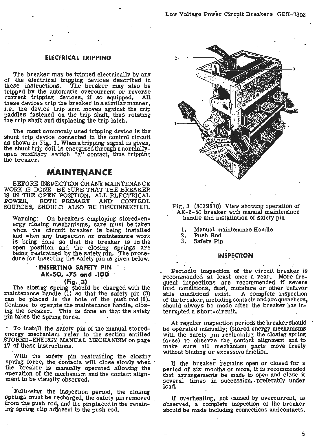
Fig. 3 {8039670) View showing operation of
· AK-2-50 ·
breaker
with manual maintenance
handle and installation. of safety pin,
1.. Manual maintenance 'Handle
2.
Push
Rod
3.
Safety
Periodic
recommended ·
quent inspections
Pin
INSPECTI
inspection of the
at
least
once a
are
recommended
load. conditions, dust, moisture or_
-
able conditions
.of the
breaker,
should always
exist.
A complete inspection
including contacts and
be
made
after
terrupted a short-circuit.
At
regular
be
operated
with the
force)
make
fo
sure
without binding
If
the
period
that
of
arrangements . be
several
inspection periods the
manually; (stored energy mechanisms ·
safety
breaker
pin
observe
all
or
six
months
restraining the closing spring
the contact alignment and to
mechanism
excessive friction.
remains
or
more,
made to open and close
times
in succession, . preferably under.
load.
If overheating, not caused by overcurrent,
observed, a complete inspection
should
be
made including connections and contacts.
ON
parts
-open
circuit
year.
other
arc
the
breaker
breaker
move freely
or
closed
it
is
recommended
of
the
break~r
· More
if
fre-
severe
unfavor
quenchers,
has in-
should -
for
breaker
is
a·
it
is
5
GEK-7303 Low Voltage
Power
Circuit
Breakers
TROUBLE
Overheating
to Trip
Failure
AK-2
Breakers
Failure
to
AK-3
Breakers
Trip
TROUBLE
SHOOTING
CAUSE
Contacts not aligned.
Contacts
with
Contacts
dirty,
greasy
burned
or
or
dark
film;
badly
Current-carrying surfaces
coated
pitted.
dirty.
Corrosive atmosphere.
Insufficient bus
Bolts and nuts at terminal connections
uot
tight.
Current in excess
or
cable capacity.
of
breaker rating.
Excessive ambient temperature.
Inductive heating;
of
Travel
positive release
Worn
- Binds in overcurrent
Loose
Disconnect Plugs.
Loose
Tap Connections. -
tripping device does not provide
gt tripping latch.
or
damaged
or
or
trip
unit
parts.
trip
de.vice._
Disconnected Power Sensor
Broken Power Sensor Coil
·
REMEDY
Adjust contacts.
Clean contacts.
Rep~ace contacts.
Clean
surfaces
carrying
Relocate
enclosure.
Increase
Tighten, but
limit
of
breaker
Check
circuit
of
parta.
or
capacity
bolts
by
current-
proVide adequate
of
bus
do not exceed,
or
fittings.
application
_decreasing load. _
or
or
cable.
elastic
ProVide adequate venWation. C~rrect
bus
or
· cable arrangement.
Re-adjust
Replace
Replace
Tighten
Plugs.
Tighten
or
_ replace tripping device.
trip
unit.
overcurrent
or
Reconnect Disconnect.
or
Reconnect Tap Connections.
trip
device.
modify
__
False
Tripping
AK-2
Breakers
False
AK-3
Failure
and Latch
Burned
Contacts
Tripping
Breakers
.
to
Close
Main
Overcurrent pick
Overcurrent time setti!)g too
Bind
in
overcurrent trip device.
Captive Thumb Screw
Loose Fail-Safe Circuitry Reverts .
Characteristic to Minimum Setting
and Maximum Time Delay.
Tap Setting Dial on Power Supply
Incorrectly Set.
External Ground Sensor Coil
Improperly Connected.
Binding in attachments preventing
resetting
Latch out
return
Latch
Hardened
Safety pin left
up
too low. _
on
of
latch.
of
adjustment.
spring too weak
or
gummy lubricant.
in push rod.,
short.
Power Sensor
or
broken.
Motor burned out.
Faulty control circuit component.
Improper contact sequence
not sufficienUy parted
part).
Short.circuit
rupting r.ating
of
contact wipe
Loss
.
current
of
breaker.
when
leJel
or
pressure.
(main contacts
above
arcing contacts
inter-
Check application
trip
deVice. ·
Check appllcatiOn
trip
deVice.
Replace
Setting.
Set Dial
Sensor Coi! Tap.
Refer
of Shield and Conductors Connecting
the
overcurrent
Tighten Thumb Screw on
to Correspond with Power
to
and Connections. Check Continuity
Fig.
External
of
overeurrent
of
overcurrent
trip
device.
Desired
40 Page 38
Ground Sensor Coil
for
Pola_rity
Re-align and adjust attachments.
Adjust latch,
~eplace
spring.
Clean bearing
and
latch surfaces,
Remove safety pin,
Replace motor.
Replace
Increase
contact sequence by raising
ing
main
ReQuires
replacement
quate interrupting capacity.
Replace
and
dress
,.
-
or
adjuat faulty device.
arcing contact wipe. Adjuat
movable
stationary contact
contact pivot block.
system
study
With
breaker haVing
. up
or
replace contacts. _
and
or
lower-
possible
springs
ade-
6

At
all. times
pencil
ials
breaker
lines,
to
remain
as
they may
points of different potential and
electrical
The
at
a
circuits
electrical
~reakdown.
breaker
rated
are 'properly
attachments
it
is
important not
paint,
oil
or
on the insulating
cause
should-
voltage
be
to
assure
connected and
are
.other
foreign
surf
low
resistance
result
operated
that the control
functioning
to
·permit
aces
in
several
that
properly.
A complete contact inspection, including con-
tact
wipe and ·
lar
inspection
short
circuit
determine
pitted
or
in
replaced.
quenchers
ing contacts and
replaced
original
erate
and
thickness.
In
general,
lubrication.. _Mechanical bearing points
sliding
regular
G-E
Lubricant
tact
surfaces
ricant
be
using
BE
OF
D50H47. Hardened
removed
kerosene.
REMOVED
DIRT OR
pressure,
periods
current
whether
which
It
to
properly
when they
the
surfaces
inspe
_ction
D50Hl~ . Sli<lingsilver plated con-
should
from
ALL
TO
DUST
should be made
and always
has been
the
contacts
case
is
they should be
necessary
to
inspect the contacts.
arc
quencher
are
LUBRICATION
circuit
barriers
eroded to half
breaker
should be lubricated
periods
be
with a thin film of
lubricated with G-E Lub-
grease
latch
and bearing
EXCESS
AVOID ANY
LUBRICANT
. ·
after
interrupted,
are
worn
remove
should be
requires
and
dirt
surf
ACCUMULATION
mater-
of the
between
eventual
times
all
at
regu
-
a known
to
or
dressed
the
arc
Arctheir
mod-
at
the
should
aces
by
SHOULD
Low Voltage
5. Remove the auxiliary
··
(5-,
Fig.
20).
6. Check along the·
anical
interference
overcurrent
Power
Circuit
or
trip
device and the
Breakers
switch
trip
shaft
connection between the
Remove mechanical · connection if
if
interference
removing
to
avoid mechanical breakage of
or
reassembling
frames
the
should
trip
shaft
NOTE
:
be
fastened to a suitable maouting
the
front
as
the bolts
BASIC
The
arc
regular
cracked
thickness, they should be
inspection
1. Be
or
sure
exists,
re-assembling
use
extreme
front
and
trip
the
front
and
rear
frames,
be
is
hori
zontally aligned.
It
is
recommended
frame
supported by a sling
are
being installed.
BREAKER
ARC QUENCHERS
(Fig •.. 4
positioned
vertically
that
COMPONENTS
and ·5)
quenchers should be inspected
period.
eroded to one-half
REPLACEMENT-AK
the
breaker
If
rep_lacec;i
BREAKERS
is
open.
the
their
.
2. Remove the channel-shaped retaining
by removing two
3.
Lift the quenchers
arcin
g co~tacts.
screws
and two
clear
nuts.
of the· movable
GEK-7303
operating
for
trip
present,
care
back
rod
a mech-
paddles.
or
when
frames
devices. In
the two
so
that
the
breaker
base
with
or
hook
at
the
barriers· are
original
bar
The
use
should
become
destroy
be
entangled
the
On drawout
disconnect
Grease
Specificati~n D50H47. .
To
repair
anism, ox:
frame
must
To -separate
1. · _ The
the
safe!}7
2.
_
part
from
using a
include
Remove ·the two opening
o! the
3.
Remove the clevis pin (14,
the
center
4.
Remove the
socket
the
of
cotton waste to wipe
avoided,
as
under
the cotton ravelings may
the
bearing
bearing
surfac.e of the bearing.
breakers,
studs
SEPARATION OF FRONT
the
should -be
AND
or
replace
overcurrent
be
separated
the two
breaker
pin
in
place.
the contact
greased
REAR
FRAMES
contacts·, operating mech-
devices, the front
from
the
frames
contacts
pro~eed
must
(See MAINTENANCE.)
springs
~reaker)
from
the
outside
Fig.
pole unit.
six
nuts
from
wrench with an extension.
two nuts
at
the top of the
surfaces
surfaces
surface
· with G-E
back
as
follows:
be
open with
(on
pole units.
6)
(13, Fig.
the back
and
of the
frame.
lower
7)
frame
These
frame.
4.
.During _replacement be careful
overtight~n the
shaped retaining
will bow the
cher
loose. · · ·
·
The
is
breakers
except
the
center-pole
similar
that
breaker
to· the
and
the
open and the
Replace the
Type AKF
1. Be
breaker
sure
screw
bar
REPLACEMENT-
arc
is
replaced
breaker
which
bar.
Overtightening the
and leave the
arc
quencher of
·AKF
secure
center
BREA~ERS
these
quenchers of the standard
in a
similar
must be closed. With
closed the center-pole contacts
arc
quencher can be remov.ed.
outer-pole
as
follows:
the
breaker
arc
quenchers of the
is
open.
r.iot
to
the channel-
screws
arc
quen-
breakers
manner,·
are
2. Remove the two channel-shaped r_etaining .-
bars
which
bear
against the front of the
arc
quenchers by removing four -screws, two on each
side.
3.
Lift .the
-
arc
quenchers
clear
of
the movable
arcing contacts.
arc
4. Replace
screws
quenchers and
holding the retaining
insert
bars
the
four
in position.
GEK-7303 Low Voltage
Power
Circuit
Breakers
. . . . . .
1·· 2
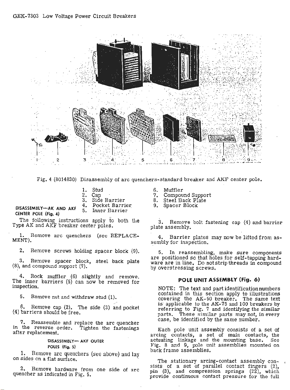
Fig.
4 (8014830)
Disassembly
1. Stud
2. Cap
3. Side
DISASSEMBL
CENTER
POLE
The following
Type
AK
and AKF
1. Remove
MENT).
2. Remove
3. Remove
Y~AK
(Fig.
AND
4) -
instructions
breaker
arc
quenchers
screws
spacer
AKF
holding
block,
4.
5.
center
(8), and compound support (7).
4. Rock muffler
The
inner
barriers
(6)
slightly and
(5)
can now be
inspection.
5. Remove nut and withdraw
6. Remove cap (2). The
(4)
barriers
7.
in
the
after
replacement.
1.
on
sides
2. Remove hardware
quencher
should be
Reassemble and
reverse
DISASSEMBLYPOLES
Remove
order.
(Fig.
arc
quenchers
free.
replace
Tighten
AKF
5)
on a flat surface. ··
from
as
indicated in Fig. 5.
.
..
. :
..
.
. .
,,
, '
Pocket
Inner
apply
poles.
(see
spacer
steel
stud
side
the
OUTER
(8Ce
one
:;.:
:·::··:
~--
.·. : ·· ...
.. .
of
Barrier
Barrie~
Barrier
to
both
REPLACE-
block (9).
back
removed
(1).
(3) and
arc
quencher
the
fastenings
abov
e)
side
. . :
.-
: :
.
arc
quenchers-standard
tl1e
plate
sembly
plate
are
ware
by
remove.
for
pocket
arcing
actuating linkage and the mounting
Fig. 8 and
and
of
lay
arc
back
sists
pin
provide
breaker
6. Muffler
7. Compound
8.
Steel
9.
3.
Back
Spacer
Remove
Block
assembly.
4.
Barrier
for
inspection.
5.
In
reassembling,
positioned
are
in
line.
overstressing
POLE UNIT A
NOTE:
contained
covering
The
in
the
is· applicable
referring
parts.
case,
Each
to
These
be
identified
pole
contacts,
9, pole unit
frame
The
assemblies.
stationary
of a
set
(3), and
continuous contact
and AKF
Support
Plate
bolt
fastening
plates
so
that
holes
Do not
may now
strip
screws.
SSEMB
text
and
this
AK-50
to
Fig.
part
section
breaker.
the AK-
7 and identifying
similar
by the
unit
assembly
a
set
arcing-contact
of
parallel
compression
center
cap
be
make
sure
for
self-tapping
threads
LY
(Fig. 6)
identification
apply
to
The
75
and 100
parts
may not, in
same
number
consists
of mai~
assemblies
assembly
contact
sprin
gs (22), which
pressure
pole
.
(4)
and
barrier
lifted
from
· components
in
compound
numbers
illustrations
same
breakers
the
similar
every
.
of a
set
contacts,
base.
mounted on
fingers
for
the full
as-
hard-
text
by
of
the
See
con- ,
(2),

Fig.
5 (8019408) Disassembled
GEK-7303 Low Voltage
arc
quencher- AKF
outer
Power
poles.
Circuit.Breakers
1. Muffler Assembly
2.
3.
Spacer
Inner
Block
Barrier
4. Cap
travel
the pivot pin to
pivot point when interrupting high
earlier
· of · the
model
contacts.
pr
_event possible pitting
breakers
Steel
flexible
springs
(5)
currents. · On
braid
leads
shunt
at
the
were
used.
rhe
movable ~rcing-contact a~sembly consists
of
parallel
·able pivot
contact
pins
arms
(8)
and (19). The
(4)
carried
arcing
on two mov-
con.tacts
interleave the main · contacts and pivot with them
about pin (19).
linkages
from
the
relative
upper
motion
pin
(7)
is
obtained by.
to the
breaker
This
mechanism. . . ·
stationary
Th·e
main and
contact
and will,
and
intermediate
surface
therefore,
break
of contacts
in
Table
I.
after
main contact
contacts. The
assembly
intermediate-
includes
extends beyond the main contacts
make
before
the main contacts
the main contacts. The number
for
each
breaker
rating is· given
The movable main contacts pivof around a
stationary
lower
pin
.(7), connected by an insulated
breaker
shunting
lower
!the
con~cts
liiie
at
the
jassembly
pin (18), which holds
·block. Motion
mechanism.
the
current
is
In
from the contact ·
contact block,
pivot
also
ag~nst
pomt. The movable main contact
the pins to prevent pitting
contains main and intermediate
obtained
addition to
steer
springs
them
from
link
ste·e1
. to the
a second
(12). to tl\e
springs
directly
(17)
force
!contacts.
5. Intermediate
6.
Outer
. 7. Side
In
of contact
Plate
order
Barrier
to function
pressure
between . the movable and
Table I gives the
contact wipe. Both wipe and
cpecked during the_
MEASURING
· 1. Remove
ARC
under
QUENCHER). .
2. With the
zontal distance
contact to the
dim.
for
arcing
contacts). ·
3. Clo.
se
the
difference between the readings in items 2 and 3
to
determines
reasons
breaker.
1. Remove
UNDER
the wipe of the · contacts.
be extremely careful not to trip the
· . ·
MEASURING
(Fig.
ARC
QUENCHER).
2. Close the
"B".
3.
Open the breaker.
Barrier
properly,
a definite amount
and contact wipe must
stationary
figures
for
contact
pressure
regular
CONTACT
arc
quenchers
breaker
from
. the edge of the stationary
stationary
WIPE
(see
open,
block behind
contacts, "C" dim.
breaker
and repeat
inspection period.
(fig. 6)
REPLACEMENT
measure
contacts.
pressure
should be
the hori-
it.
for
item
For
CONTACT
6)
arc
quenchers (see REPLACEMENT
breaker
PRESSURE
and measure dimension
Place
a push-type
exist
and
-:
('.'B"
.main
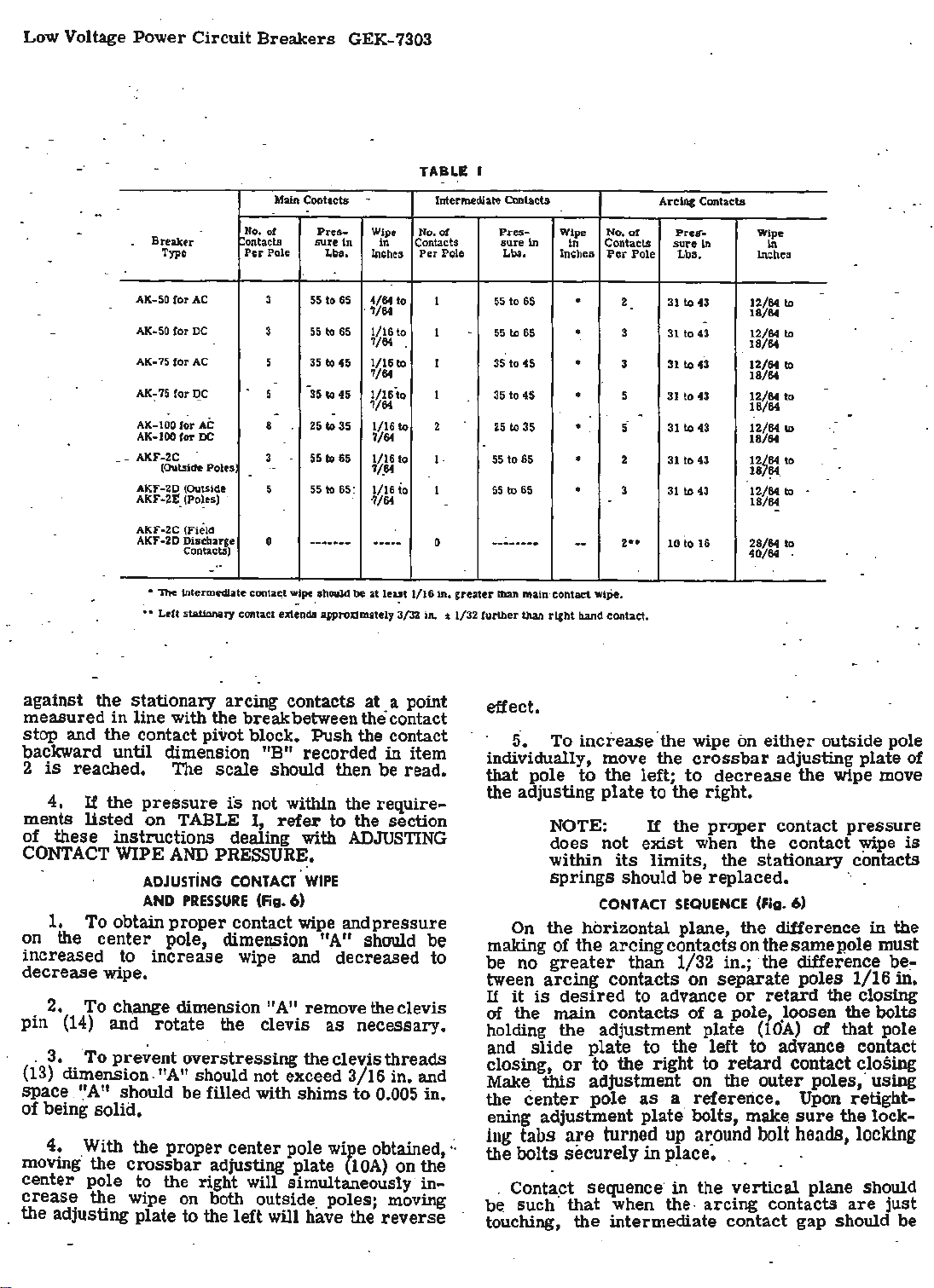
2. The
safety
scale
Low Voltage Power Circuit
Breaker ontacts
Type
No.
Per
Breakers
Main Contacts - Intermediate Contacts
or
Pole
GEK-7303
Pres-
sure
In In
Lba,
Wipe
Inches
TABLE
No.
of
Contacts
Per
Pole Lbs,
Pres-
sure
In
Wipe No.
Inches
ln Contacts
of
Per
Pole Lbs,
Arcing Contacts
Pre=r-
sure
In
Wipe
Ill
lnches
AK-SO
tor
AC
AK-SO
tor
DC
tor
AK-75
AK-75
AK-I
AK
_ AKF-2C
-
AKF-2D (Outside
AKF-2£' (Poles)
AKF•2C (Field
AKF-2D Discbarge
AC
tor
DC
00
for
AC
-100
tor
DC
(Oulside Poles
Contacta)
• The intermediate conta~t
~
•
Ldt
stationary contact ext;nda approximately 3/32 in. ~ 1/32 further than right band contact.
-
·:
..
3 55
3
55
5 35 to
-
"
35
5
-
8
25
3 55 to
.•.
.
5 55 to 65:.
0
-------
wipe
to
65
to
65
45
to
45
.
to
35
65
should be
4/64 to
. '1/64
1/16 to
'1/64 .
1/16 to
7/64
1/16
?/64
1/16 to
?/64
1/16 to
'1/.
64
1/16 io
'1/64
-----
at
le~t
to
.
.
1/16
1 55 to
1
1
I 35
2
1,
I
0
in.
against the stationary arcing contacts at . a point
in
measured
line with the breakbetweenthecontact
stop and the contact pivot block. Push the contact
backward until dimension ."B" ·recorded in item
2
is
reached. The
4.
If
the
ments
listed
pressure
on TABLE
of these instructions dealing with
CONTACT
1. To obtain
on the
WIPE
ADJUSTiNG
AND
center
scale
should then be read.
is
not within the
I,
refer
to
require-
the section
ADJUSTING
AND
PRESSURE.
PRESSURE
proper
·coNTACT.
contact wipe andpressure
(Fig.
WIPE
6)
pole, dimension "A" should be
increased to increase wipe and decreased to
decrease wipe.
· 2. To ch.ange dimension "A" remove the clevis
pin
(14)
and rotate the clevis
as
necessary.
. 3. . To prevent overstressing the clevis threads
(13)
dimension. "
space.
'.'A"
should
A"
should not exceed 3/16 in. and
be
filled with shims to 0.005 in.
of being solid.
4.
·
moving·
With the proper
the
crossbar
center pole to the right will simultaneously
crease
the wipe on both outside. poles; moving
the adjusting plate to the left will have the
center
pole
WiJ>e
adjusting plate
obtained,:.
{lOA)
reverse
on the
in-
-
-
to
to
to
-
to
.
greater
.
65
55 to 65'
35 to 45
to
45
25
to 35
55
to
65
55
to
65
-----··--
than main ·contact wipe.
•
.
•
•
•
• ·
--
2 31 to 43
3
31
3
31
5
31
-
5·
31
2 31
3
.
31
2
..
10
12/64 to
18/64
-
to
43 12/64 to
to
43 12/64 to
to
43
to
43
to
43
to
43
io
16
18/64
18/64
12/64
18/64
12/64
18/64
12/64
187?4.
12/64 to
18/64
28/64
40/64
effect.
5.
To
increase
individually, move the
that
pole
to
the
the adjusting
plate
NOTE:
does not
within
springs
CONTACT
On
the
horizontal plane,
making
be
tween
If
of the arcing contacts
no
greater
arcing
it
is
desired
·the wipe on
left;
to
If
exist
its
limits,
crossbar
to
the
right.
the
proper
when
either
outside pole
adjustin~ plate of
decrease
the wipe move
contact
the
contact
the
stationary contacts
should be replaced. ·.
SEQUENCE
(Fig. 6)
the
difference in the
on
the same pole must
than 1/32 in.; the difference
contacts on
to advance
separate
or
retard
poles 1/16
of the main contacts of a pole .loosen the bolts
holding the adjustment plate
slide
and
closing,
Make
center
the
plate
or
this
adjustment on the
pole
to
to
the right to
as
the left to advance
a reference.
ening adjustment plate· bolts,
ing
tabs
are
turned
the bolts
. Contact sequence·
be such ·
touching,
securely
that
when the. arcing contacts
the
intermediate contact gap should be
up
a:r:ound
in
p~ace. . . .
in
the
(10A)
retard
outer
make.
bolt
vertical
of
contact
poles, usmg
Upon
sure
heads,
plane should
pressure
y.,ipe
is
~e~
m.
the closing
that pole
con~ct
~los~g
retight-
the lock-
locking
are
just
Low Voltage
Power
Circuit
Breake~s
GEK-7303
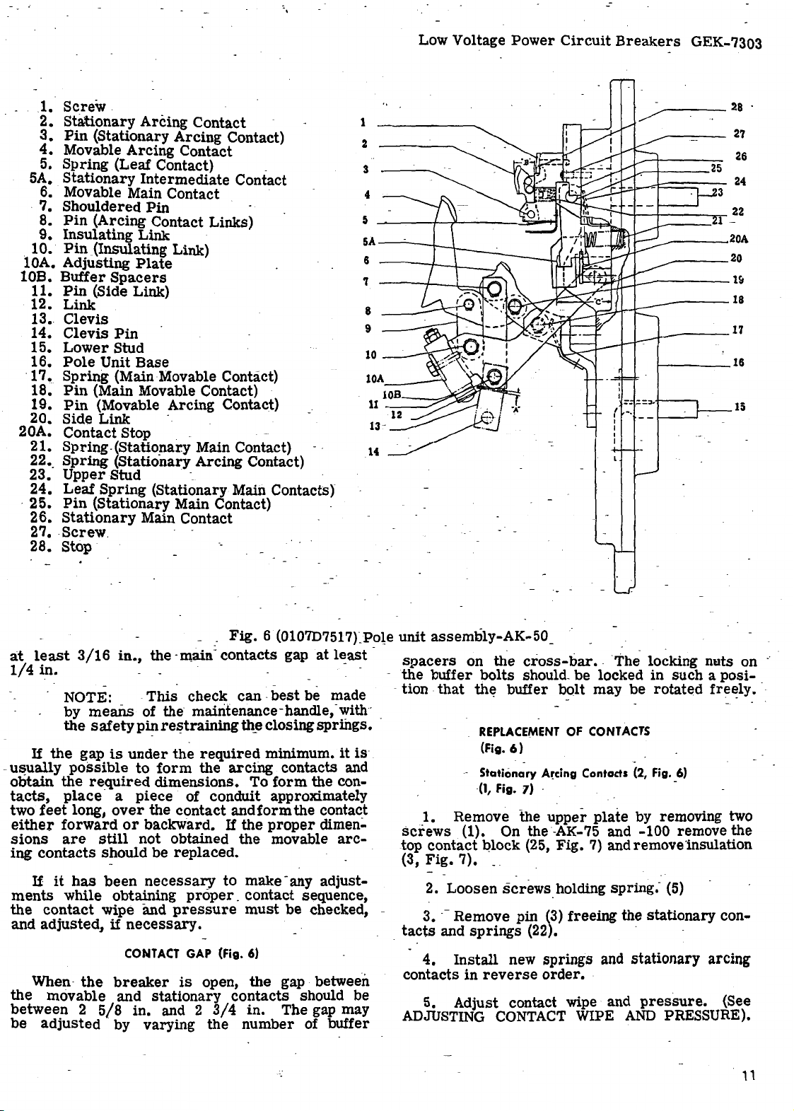
1.
2.
3.
4.
5.
5A.
Screw
Stationary
Pin
Movable
Spring
Stationary
.
Arcing Contact -
(Stationary
Arcing
Arcing
Contact
(Leaf Contact) _
Intermediate
6. Movable Main Contact ·
.
7.
Shouldered
8.
Pin
(Arcing Contact Links)
Insulating
Pin
(Insulating Link)
.
9.
10.
lOA. Adjusting
10B.
Buffer
11.
Pin
12.
13.
14.
15.
16.
·
17.
18.
19.
20. Side
20A.
21.
22 •.
23.
24.
·
25.
26.
27 • .
28.
(Side Link)
Link
Clevis
Clevis
Lower
Pole
Unit
Spring
Pin
(Main Movable Contact) ·
Pin
(Movable Arcing Contact)
Link
Contact
Spring
Spring
Upper
Leaf
Spring
Pin
(Stationary Main Contact) -
Stationary
screw
Stop
Pin
Link ·
Plate
Spacers
Pin
Stud
Base
(Main Movable Contact)
- _
Stop . - · -
-(Statio:f1ar.y Main Contact) - (Stationary Arcing Contact)
Stud -_ ·
(Stationary Main Contacts)
Main Contact
.
Contact)
Contact
1
2
3
4
5
~---t-..,,._---.....::,aa-...,
5A-~--t---\----~-
6
'l
8
9
10
-----
lOA
____
,
-
~
---------
•--r--+---+----...--
~~f/r:J__..-------1~
=-
{ -.
I
I
.J.------~l
______
___
----18
1-----16
.:=.;,,.-i----,
28
27
26
22
-
20A
20
15
·
a:t
least
1/4
3/16
in.
NOTE: -
means
by
the
safety
If
the
-
usually
obtain
tacts,
two
either
sions-are
ing
contacts
If
ments
the
and
When·
the
gap
possible
the
re_quired
place
feet
long,
forward
still
it
has
while obtaining
contact
adjusted,
the
movable and
between 2 5/8
be
adjusted · by
in.,
the ·main: contacts gap
This
of the
pin
is
under
to
form
dimensions.
a
piece
over
the
or
backward.
not
should
been
be
necessary
wipe and
if
necessary.
CONTACT
breaker
stationary
in.
varying
.
Fig.
6 (0107D7517rPote
check
- -
can . best
be made
m~~tenance-h~dle,-~ith
rel?trammg
the
th_e
required
the
arcing
'FO
closing
minimum.
contacts and
form
of conchnt approximately
contact
obtained
and
If
form
the
the
the contact
proper
movable
replaced.
to
make -any adjust-
proper_ contact
pressure
GAP
(Fig.
is
open,
contacts
and 2
3/4
the
must
6)
the
in.
number
sequence,
be
checked, -
gap - between
should be
The gap may
of buffer
at
l~ast
springs.
it
is
~e
con-
dimen-
arc-
unit
-
spacers
-
the
-tion
- _
screws
.top
(3,
tacts
.
contacts
ADJUSTING
assembly-AK-50
on
the
buffer
bolts
that
th~ buffer
REPLACEMENT
(Fig.
- Stationary
(1,
Fig.
1. Remove
_
cross-bar
should.
6)
- .
A~cing
7) -
the
upper
• . The ~ocking nuts
be
locked m
bolt
may
OF
CONTACTS
Contads (2,
plate
be
by removing two
. (1). On the -AK-75 and -100 r~move
contact
Fig.
2.
3 • . - Remove pin
4.
5. Adjust contact wipe and
Qlock (25,
7).
- .
Loosen
and
__
screws
springs
Install
in
reverse
CONTACT
Fig.
7)
and remove insulation
holding
(3)
freeing the
spring.
(22). · ·
new springs and
order.
WIPE
stationary
·
AND
stationary
pressure.
such
rotated
Fig.
a pos1-
fre~ly.
_6)
- (5)
arcing
PRESSURE).
<?D
~e
con-
(See
,,
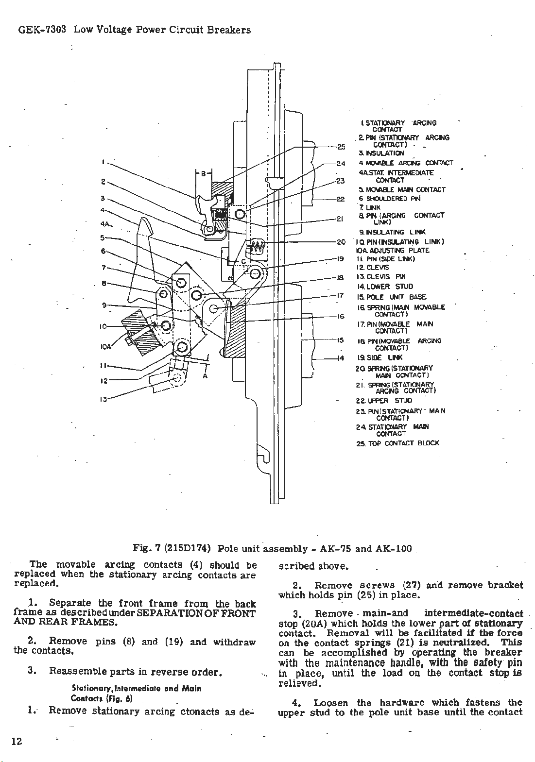
GEK-7303 Low Voltage Power
4
5
Circuit
Breakers
· I
l
I
I
I
I
I
STATIONARY
COOTACT
.
2.
P1N
(STATIONARY
25
24
23
22
21
20
19
18
17
16
5 -
4
-
CONTACT)
3. lNSULATI
4. ID.ABLE
4A.
STA
T.
CON'lllC
5.
MOI.AB.E
6
SHOULDERED
7.
LNK
a
PIN
(ARCING
LINK)
9.
INSULATING
I Q PIN ( INSll.ATING LINK )
IO
A.
A.OJUSTING
II. PI
N (S
12.CLEVIS
13. CLEVIS PIN .
LOWER
14.
15.
POLE
16.
SPRING
CONTACT)
17. PIN(MOVAEl.E MAIN
COOTACT)
1a
P1N(MOV
C
ONTACT)
19 SI
DE
2Q
SPRING (
MAN
2i
. ~ (
ARCING
-22.
Uff>ER
2
3.
PIN(STATIONARY-MAIN
CONTACT)
24.
STATICNARY
CONTACT
25. TOP COOTACT
"ARCING
-
-
OO
ARCf'.lG
NTERMEDIATE
T
MAN
CONTA
PIN
CONTACT
LINK
PLATE
IDE
.LI
NK)
STU
D
UNIT
BASE
(MA
IN
MOVABLE
ARCING
ABLE
LN<
STATIONARY
CONTACT)
STATIONARY)
CONTACT
STUD
MAl'l
BLO
ARCING
CO'JT
ACT
CT
CK
The . movable
replaced
replaced
1.
.
frame
AND
as
REAR FRAMES.
2. Remove
the contacts.
3.
1.- Remove
12
·
Fig
arcing
when the
stationary
.
Separate
described
Reassemble
the
front
under SEPARATION
pins
(8) and (19) and withdraw
parts
in
Stotio~ory,lntermediate and Ma
Conta
d1
(Fi
g. 6) _
stationary
. 7 (215D174)
contacts
(4)
arcing
frame
reverse
arcing
from
order
in
ctonacts
Pole
should
contacts
the back
OF
FRONT
.
.
as
unit ·
be
are
de.;.
assembly
scri
- AK-75 and AK-100 .
bed above.
2. Remove
which holds
3.
~in
Remove .
stop (20A) which h.olds
contac
t.
Removal
on the contact
can
be
accomplished
with
the maintenance
in
place,
·
relieved.
until
4. Loosen
upper
stud
to
the pole unit
screws
(25)
(27) and remove
in
place
•
main-and
the
lower
will
be
springs
facilitated
(21)
is
by operating the
handle,
the
load on the contact
· ·
the hardware
base
bracket
intermediate-contact
part
of
stationary
if
the
neutralized.
force
This
breaker
with
the
sa!ety· pin·
stop
is
-which
until
fastens
the
contact
the
.

Fig.
8 (8014678)
Front
view of back
assembly
- AK-2-50
frame
Low Voltage
Power
Circuit
Breakers
GEK-7303
Stationary
1.
Contact
Movable
2.
Contact
Stati9nary
3.
Contact
Clamp
4.
Movable Main
.
5.
Contact
spring
lift
5.
out
. ·
load
Remove
contacts.
~--Reassemble
being
in
described
at
th~
·
1.
2.
3.
·
bottom
careful
proper
Remove
above.
Loosen
Remove
of
Arcing
Arcing
Main
:
on
pin
pin
to
position.
Movable
_
Main
the
spring
braid
contact.
(25)
is
(~5i and
contact.s
replace
Intermediate
Contacts
movable
(17).
if
6.
Crossbar
Series
7.
Device
Movable
8.
mediate Contact
Stationary
9.
_mediate Contact
relieved.
screws
in
the
intermediate
(F1g.
and
6) ·
arcing
present
by
· ·
Overcurrent
Inter-
Inter-
(27)
and
reverse. orger,
contact
·
contacts
removing
as
screw
Fig.
9 (8039669)
1.
.
2.
·
3.
ing contact
Power
Disconnect
Tr;msformer
replacement
Front
·. ··
assembly -AK-3-50
Sensor
view of
Coil
Assembly
Plug ·
Taps
in
!
.
back
Amper~s
frame
(See ADJUSTING CONTA_CT WIPE AND PRESSURE).
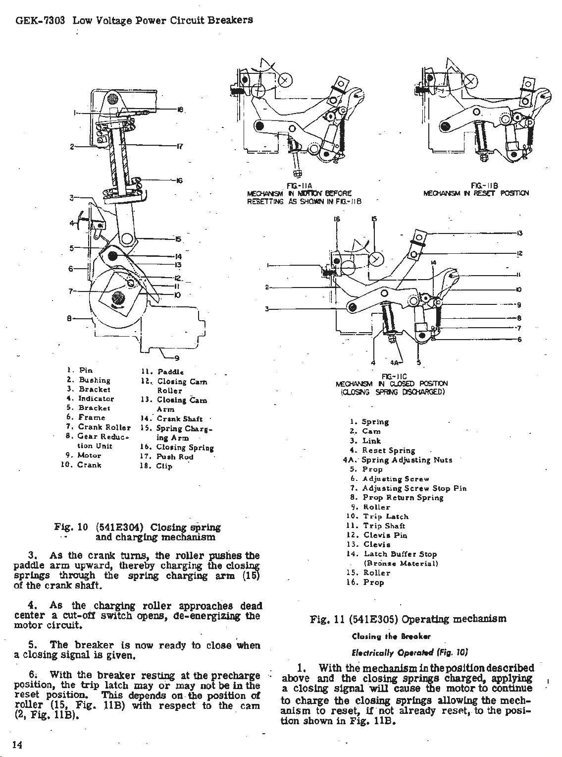
OPERATING -MECHANISMS
ELECTRICALLY
and
.
The
ele~trically
a
motor
the closing
shaft (14,
with a
closing
closing
llC.
and
center-pole
crossbar
.
of the
contacts
-100;
and a
Fig.
roller
cam
cam
it
OPERATED
MANU~L
gear
springs
10). The
(12,
(2,
Fig.
roller
The
closing
unit
through a
controls
~m
all
AK ·
.AK-50,
-50
-75
·
operated · mechanism
reduction
(16,
Fig.
11).
is
shown in·
unit,
Fig.
10) through a
crank
shaft
10) which
The
which charges ·
ha~ an
rides
position· of
Fig.
11A,
cam is. connected to the
clevis
and through a
the opening and closing
pole
units.
includes
crank
arin
on the
this
11B,
4.
(7).
5.
sid~
to
be
6.
Always
Slide
link
Slide ·pins
to
allow
replaced.
Reassemble
check
(12) to the
(7)
the
movable
parts
contact wi
and (18)
intermediate
in
reverse
pe
and
side
and off of p4l
far
enough
order.
pressure
to
the
contacts
follow-
1.
The
Fig.
llA.
2.
The motor turns the crank
is
mounted
tion unit.
face of
on
it.
Chargi
ng
mec~anism
on
The
the
crank,
the Closing Springs (Fig.
in
position
the
output
charging
has
shaft
roller,
paddle
of
arm
10)
is
the
gear
which
(11)
shown
(10)
is
in
which
reduc-
on the
bearing
13
..
GEK-7303 Low Voltage
Power
Circuit
Breakers
·
~C>IANSM
RESETTING
FIG
~
·IIA
N
t.1111:lN"
AS
SHOWN IN.
BEFORE
FIG.-
I I B
~CHANSM
FIG.-
N
116
RES€T
POSITlCN
3.
paddle
springs
of the
_5
6
7
Pin
1.
Z..
Bushing
3,
Bracket
4 .
Indicator
5.
Bracket
6.
Frame
7,
Crank
8,
Gear
tion
9.
Motor
10,
Crank
Fig.
10 (541E304) Closing
· · and
As
the
arm
upward, there~y
through the
crank
shaft.
Roller
Reduc
Unit
crank
11,· Paddle
lZ.,
13.
1'4:
15.
..
16.
17,
18,
chargin
turns;
spring
15
14
13
·12_
II
IO
··-
~-
Closing
Roller
Closing
Arm
Crank
Spring
ing
Closing
Push
Clip
g mechanism
the
Cam
Cam
Shaft
Charg-
Arm
Spring
Rod
spring
roller
chargi~
charging
·
pushes the
the closing
arm (15)
13
~2
2
3
Spring
.•
Cam
Link
Reset
Prop
Adjus.ting
Adjusting
Prop
Roller
Trip
Trip
Clevis
Clevis
Latch
(Bronze
Roller
Prop
FIG.-IIC
N
a..osED
SPRf'lG
Spring
Adjusting
Return
Latch
Shaft
Pin
Buffer
POSITl()'.I
ClSOtARGED)
Nuts
Screw
Screw
Stop
Spring
Stop
Material)
Pin
tJE:CHANSM
(CLOONG
1.
z.
3.
4 .
4A,· Spring
5.
6.
7.
8.
9.
10.
11.
lZ..
13.
14.
15.
16.
()
···
--9
-8
·7
6
4.
As
center
motor
5. The
the
a cut-off
circui
t.
breaker
a closing signal
6. With the
· position, the
reset
roller
(2,
14
position.
(15,
Fig
. 11B).
. charging
switch
is
breaker
trip
This
Fig.
llB)
is
roller
opens,
now
approaches
de-energizing
ready
to c
given.
latch
resting
may.
or
at
may
depends on. the position
with
respect· to
lose
the
precharge
not be
the
dead
the
when .
in
the
of
cam
1.
··
above
a
closing
to
charge
anism
tion shown
Fig.
11 (541E305) Operating mechanism
With
and
to
reset,
Closing
Electrically
the
the
signal
the
in
Fig. UB.
the
Operated
mechanism
closing
·
will
cause
closing
springs
u· not
halter
in
the position
springs
the motor
already
(Fig.
charged, applying_
allowing
resP.t, to
10)
described
to
co
ntinue
the
mec~-
the
posi-

Low Voltage
•1:
.
Power
Circuit
'
..
Breakers
. . ' ;
.. ~ ..
': .
...
~. ··
GEK-7303
:··
·•. -
Fig.
1i
(8018989)
AK-50 showing
~
2.. As
dead-center
position) the
Crank (10)
motor so-
center
·
3.
the
crank
to
rotate
F.ig.
11).
llC)
in
4. Raising
breaker
Tripping the Breaker (Fig.
·Operation
the
trip
to
release
forces
reposition
the
position
the operating ·
Adjustments (Fig.
the
crank. roller
position,
closing
can
be
that
roller
position
As
this
without
the
springs
shaft
cam
Prop
position
'(14)
(2,
(16,
clevis
contacts
of
-any
shaft
(11)
the
latch
of the· contact and opening
the
operating
shown
cycle
11)
Rear
view of
cam
shaft
locking plate
being loosened
(7)
(maximu.m
springs
overdriven
(7)
are
independently of the
assumes
restraint.
free
its
:-
discharge,
causes
Fig.
Fig.
roller
11) and
11) holds
raise
~
(13,
Fig.
llC)
through the pole
11)
of
the
trip
devices
which ;µlows
prop
(5).
the
This
mechanism linkage to
in
Fig.
may
llA,
be
repeated.
In
fronnrame-
passes
spring
its
charge
to
discharge.
top
bottom dead-
the rotation of
(15,
Fig.
11)
clevis
cam
closes
base
(13,
(2,
Fig
the
linkage.
rotates
trip
latch (10)
allows the
springs
this
position,
to
Fig.
manual
and with
roller
1/64 in, and
obtained by
should
.
latch
be
reposition
(3) and
1/
32
the nuts (4A)
.the
Replacement
to the
AND
these
..
.!:.:
Fig.
13
(8018984)
AK-50 showing
~nd
llB.
(The mechanism should
operation
1.
roller
The
(9) of
(15)
gap between.the
the
1/32
turning sc.
2.
·
The
center
pass
through
buffer
stop
adjusted by loosening the retaining
the
3.
The . distance
prop
in.
reset
(5) should be between 1/64 in. and
To
obtain this gap, advance
spring
Rear
view of front
cam
shaft
cam
shaft
removed -
with_ the safety pin
clear
of
cam-(2).
trip
reset
the
latch should be between
in.
This
rew
(6).. - · -
line
of the
center
of the
on the mechanism
latch
with respect to the
between ·the
on
-the bottom of the
(4).
frame-
locking
plate
be
reset
in
latch
(10)
adjustment can be
trip
latch (10)
roller
(9). The
frame
screws
roller
or
~d
When replacing the operating mechanism,
section
BACK
titled
FRAMES
SEPARATION OF FRONT
under
MAINTENANCE
instructions.
by
place
.and the
can
to
roller.
on
link
retard
~ing
refer
in
All
ting
mechanism· in
adjustments
should
the
reset
be
made with the opera-
position
as
shown in
The
motor
is
mounted on the side of
the
g
ear-
15
 Loading...