

Page 1
MAINTENANCE
(SUPPLEMENT)
MANUAL
(Supplement
GEI-86134D
to GEK-731
0)
POWENCINCuIT
TYPE
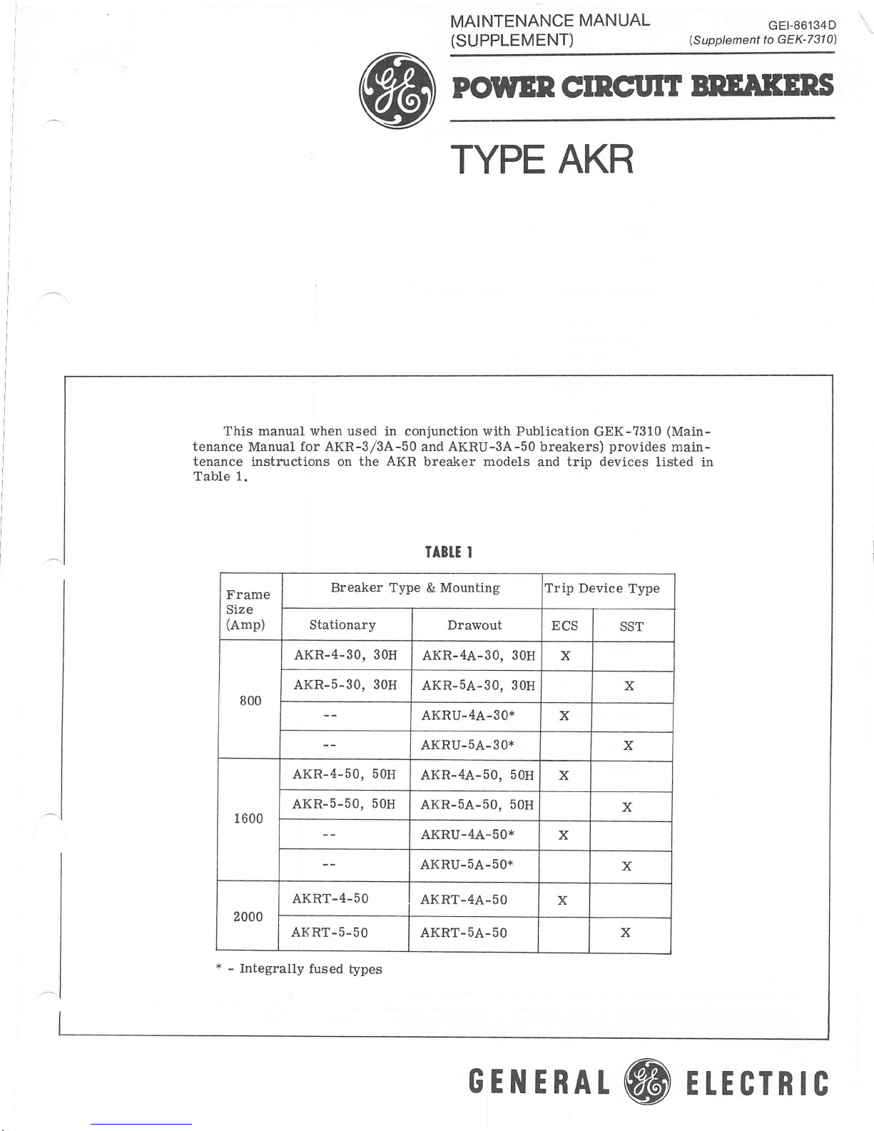
This manual when used in conjunction with Publication
tenance
tenance
Table
1.
Manual
instructions on
for AKR-3/3A-50
the AKR breaker models
AKRU-3A-50
and
AKR
breakers)
and trip
GEK-7310
provides
devices
BNEAKENS
(Main-
main-
listed in
Frame
Size
(Amp)
800
1600
2000
*
Integrally
-
Breaker
Stationarv
AKR-4-30,
AKR-5-30, 30H
AKR-4-50,
AKR-5-50,
AKRT-4-50
AKRT.5-50
fused
30H
50H
50H
types
IAB]T I
Type & Mounting
Drawout
AKR-4A-30,
AKR-5A-30.
AKRU-4A-30*
AKRU-5A-30*
AKR-4A-50,
AKR-5A-50.
AKRU-4A'-50*
AKRU-5A-50*
AKRT-4A-50
AKRT-5A-50 X
Trip Device
ECS
3OH
30H
50H
50H
Type
ssr
X
x
X
X
X
X
x
x
x
GENERAL
@
ETECTRIC
Page 2

Introduction
CONTENTS
Constructional Diff
erences.
.
Breaker Ratings
Drawout Breaker Interchangeability
Breaker
Maintenance
. .
Precautions
Manual Handle
Adjustment
ContactMaintenance. . . .
Contact
Adjustment:
AKR.3O,
AKR-50,
-30H,
-50H,
AKRU-30
AKRU-50
.
.
AKRT-50
Contact Replacement:
AKR-30,
-30H,
AKRU-30
.
AKR-50, -50H, AKRU-50, AKRT-50. .
FusedBreakersAKRu-30,
-50
......
FuseSizesandMountinC....
Special
Open
Type SST
2500A
Fuse
Overcurrent
Fuse.
Lockout Device 12
Trip Device t4
Components 14
TripCharacteristies ......16
Troubleshooting. 77
Test Set TAK-TS1.
SST
False Tripping
Replacement of
(Ground
Current
Flux Shift Trip Device
Cabling
Ground
Diagrams. 22
Fault Defeat
. .
.
Fault)
Sensors 19
Cable
. .
6
o
6
o
7
I
8
10
10
10
10
72
18
19
20
23
Type ECS
Overcurrent
Components
TripCharacteristics .,,,..25
Cabling
ECS
& SST Time-Current
fhese inslruclions do nol
with instollolion,
lhe purchoser's purposes,
for
operolion
purporl
lo
oll
cover
or moinlenonce.
lhe
moller should 6e referred lo lhe
detoils or voriations in
Should further informolion
Trip Device 24
24
Diagram 26
Curves
eguipmenl
be desired or should
Generol Eleclric Compony.
nor to provide for
every
porliculor problems
27
possrble
conlngency lo be mel in conneclion
orue whrch
nol covered
ore
sufticienlly
Page 3
Power Circuit
Breokers,
GEI-86134
MAINTENANCE
LOW.VOLTAGE
INTRODUCTION
The data in this supplement
800A
oreakers not coveredby the
maintenance manual
formation
devices
1600A frame AKR-50 design.
c i-f ic const ructional di-f
basic AKR-50 framework,
devices
Except
the
Accordingly,
now
new types.
the
to that
to the
AKR-30 and
the
on
also is included.
new
The
breaker models
are substantially
for the
external
in
scope
descriptive
new models.
Hx W xD dimensions
a majority
publication
Therefore, to
of this supplement
or otherwise discussed
continue to
erational
employ
information source.
the
2000A
existing
(publication
new
ECS and SST solid-state
f
rence
e
mechanism
common
800A
frame
of the
GEK-7310 applies
avoidneedless repetition,
and instructional material
Unless
herein,
GEK-73i0 as
MANUAT
SUPPLEMENT
POWER CIRCUIT BREAKERS
TYPES AKR/AKRU.3OI50, AKRT.sO PER TABLE
pertains
AKRT-5O
GEK-7310).
derivatives
are
Apart f rom the
s identi-f ied bel
primary
AKR-50
is
confined
noted
the user
the
to
the new
f rame
AKR/AKRU-50
In-
trip
the
of
spe-
the
ow,
and accessory
to all versions.
details,
stud
are identical.
in-formation
equally to the
principally
unique
to the contrary,
should
general.
op-
AKR-30H.
cauons
a.
b.
c.
d.
ln rne rollowlng
quenchers.
Arc
Closing
insulation
Extra
Mounts one
for
total
a
ture is
NOTE:
AKR-30,
qttencher
red.
Same as
springs.
additional
four:
of
same as
To
uisibly disti.ngtdslt i,t
tlte clositzg springs and at,c
couers
I
the
AKR-30
areas:
sha-ft flyweights.
on
stationary main
otherwise
AKR-30.
of
See Fie.
tlte 30H are colored
except for
the
contact struc-
6.
ft,ont
modifi-
contact
tlte
Complementing
supplernent
pand
and update
where
operating
tion
appropriate.
handle
of the AKRU-5O
includes
the
above
additional
existing
Examples
adjustment
minimum
to 450A.
CONSTRUCTIONAL
features
The
AKRT
are
refer to
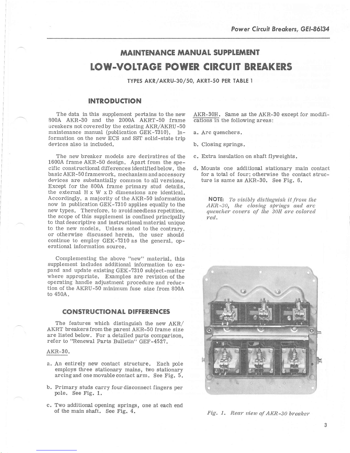
AKR-30.
a.
b.
c.
breakersfromthe
listed
below.
"Renewal
entirely
An
employs three
arcingand onemovablecontact
Primary studs
poie.
Two
of
See Fig. 1.
additional opening springs,
the
main shaft.
which distinguish
parent
For
detailed
a
Parts Bulletin"
new contact structure.
stationary mains, two
carry four disconnect fingers
See Fig. 4.
"new"
information to
GEK-7310
are revision
procedure
fuse
DIFFERENCES
AKR-50
parts
GEF-452?.
arm. See Fig.
material,
subject-matter
and reduc-
size from 8004.
the
new
frame
comparison,
Each
stationary
one
at
this
ex-
of the
AKR/
size
pole
per
each end
5.
Fig, 1.
Rea?'
uiew
AKR-50
of
breaker
Page 4
GEI-86134,
Power
Circuit
Breokers
AKR-5OH.
?ffiEs
springs
closing
the
attaine$-by
and
springs
AKR-30H.
AKRT-50.
AEF-:$;-
a.
New
and larger
contact
b.
Stationary
otherwise
to the
AKR-50.
An
added
A
M
o dif i
arms
the
AKR-50
currry
20004
cations
upper
and
main
stationary
See
with
extended
special
arc
insulation.
the
same
extension
ar e
:
stud
pivot
block.
contacts
Frame
Size
(Amperes)
Figs.
increased
contacts
g
short
quenchers,
euencher
red
color
the
of
1600A
assembly,
from
are
and 9.
Breal<er
Type
circuit
closing
tops
and
used
frame
movable
6 to
identicai
TABI.T
BREAKTR
Rated
Maximum
Voltage
(60H2
--
AKR
800,
on
present
of the
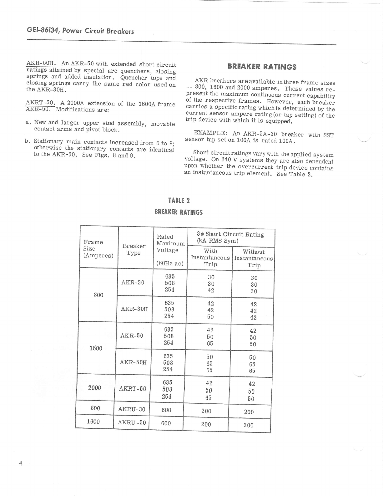
carries
current.sensor
trip
device
EXAMPLE:
sensor
g;
Short
voltage..
upon
an instantaneous
2
RAIIIIGS
3{
(kA
Instantaneous
ac)
BREAKER
breakers
1600
and
the
maximum
respective
a specificrating
€rmpere
with
which
An
tap
set
on
cir
cuit
ratings
OTZ
whether
Short
RMS Sym)
V
!
the
Circuit
with
Trip
RATINGS
a.reavailable
2000
amperes.
continuous
frames.
whichis
rating(or
it
is
AKR-5A-3O
1004
is rated
vary
systems
overcurrent
trip
element.
Rating
Without
Instantaneous
Trip
inthree
These
current
However,
determined
tap
equipped.
breaker
100A.
with
the
they
are
trip
See
frame
sizes
values
capability
each
breaker
by
setting)
applied
with
system
of tt"
SST
atso Oependent
device
lante
contains
Z.
re_
the
800
1600
2000
800
1600
AKR-30
AKR-3OH
AKR-50
AKR-5OH
AKRT.SO
AKRU-30
AKRU
-50
508
254
635
508
254
635
508
254
635
508
254
635
508
254
600
600
635
42
50
65
200
200
42
50
65
50
65
65
30
30
42
42
42
50
30
30
30
42
42
42
42
50
50
50
65
65
42
50
50
200
200
Page 5
Power Circuil
Breakers,
GEI-86134
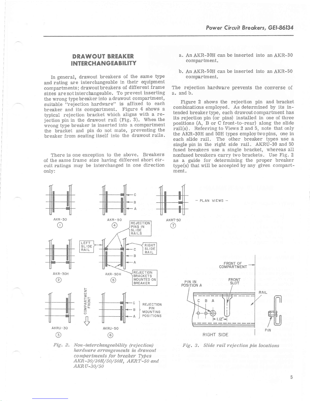
DRAWOUT
INTERCHANGEABILITY
general,
In
rating are
and
compartments
sizes are
the wrong
suitable
breaker
typical
jection
wrong
rejection
pin
type breaker
drarvout
interchangeable
drawout breakers
;
interchangeable.
not
breaker
type
"rejection
its compartment.
and
in the
the bracket and
breaker
of
cuit ratings
onlv:
.f r(
from seating
There
the same
ilil
ill
is one
frame
may be interchanged
]l
ill ltl
ilt lll
T-n-
AKR.30
o
sa1
'il_
ttt ltl
ilr
tl
|ll
ll| ilT
uu
AKR-3OH
(?
n^<
il ltl
lrlr-
tl atl
tt ttl
T-T
AKRU.30
(c,
breakers
into a
hardware"
bracket
drawout
is inserted
pin
do not mate,
itself
exception
size having
ffihffi
z
UJ
F-
F2
<x
o
n
v
II TI
ffil--c I
+-il1'-' i"oJ'JT,rn
T----l;l*A
BREAKER
the same
of
their equipment
in
diJf er
of
prevent inserting
To
drawout
is a-ffixed
Figure
which aligns
(Fig.
rail
into
a
the drawout
into
to the above.
different short
in
-
AKRU
50
(6)
type
fr
ent
ame
compartment,
to each
4 shows a
with a
3). When
compartment
preventing the
one
RE.JECTION
PINS IN
SLIDE
LS
RAI
REJECTION
BRACKETS
MOUNTED
BREAK ER
J
re-
the
rails.
Breakers
cir-
direction
R IGHT
SLIDE
RAIL
ON
neuecrroru
PosrrroNs
a.
An
AKR-3OH
compartment.
b.
An AKR-50H
compartment.
rejection
The
and b.
a.
Figure
combinations
tended breaker
2
its rejection
positions
rail(s) . Referring
the
each
single
fused breakers
nonfused breakers
as a
type(s)
ment.
AKRT.50
@
(A,
AKR-30H
slide rail.
pin
in the right side
guide
that will be accepted
PLAN VIEWS
-
can be
can be inserted into
hardware
shows
employed.
type,
(or
pin
B or C
to
50H types employtwopins, one
and
inserted into
prevents
the rejection
As determined by its in-
drawout c
each
pins)
installed in one of
the
pin
ompartment
front-to-rear) along
5, note that only
Views
2 and
The other breaker
AKRU-3O ard 50
TaiL
use a single bracket,
carry two brackets. Use
determining the
for
-
KrtJn I sluE
by any
proper
given
an
AKR-30
an
AKR-50
converse
and bracket
has
three
the
slide
types use a
whereas
Fig.
breaker
compart-
ffi
IN
of
in
a-ll
2
Fig.
2. Non-interchangeabi,lity
hardware arrangements
compartments
AKR
-30/s0H/50/50H,
AKRU-30/50
breaker Types
for
AKRT
(rej
ec ti.on)
i.n drawout
-50
and
Fig. 3. Slide rail rejection
pi.n
locations
Page 6
GEI-86134,
Power
Circuil Breokers
BREAKER MAINTENANCE
SAFETY PRECAUTIONS
BEFORE INSPECTING
ANY XMINTENANCE WORK
BREAKER, I7: MUST BE DISCONNECTED
FROM
POWER AND CONTROL, AND BE IN
THE
MANUAT
On
springs may be charged
gree
clockwise handle
strokes
procedures
stroke method. By
operation
Referring
handle adjustment is
The length of
double-ended
mid-stud can be
When looking
wrench clockwise
motion
degrees.
wrench stroke imparts 15 degrees movement.
best setting is approximately mid-range.
ALL VOLTAGE
'IOPEN"
HANDTE ADJUST'NENT
manually
lesser
of
should
is
assured.
shortens it. The
In
POSITION,
operate d AKR
-
swing. The following
be
so
to Fig.
this link is
stud in its center.
engaged by an open-end wrench.
down
on the breaker, turning the
lengthens
the
confined space available,
stroke
performed
doing, proper
13
made
OR BEGINNING
ON THE
SOURCES, BOTH
bre ake rs, the closin
ei.ther by a single
to four
or up
adjustment
using the single-
multi-stroke
of GEK-?310,
via adjustable
controlled
the
link.
range
of adjustment
the manual
by turning
A hex
section in
The opposite
135
multiple
link
is 300
de-
(16).
each
The
link
If the
extend the closing spring
center.
is too long, the handle
this
In
to complete the
then
be closed and opened
shortening of the link.
link
If the
possible.
not
charge the springs.
is too short,
However, more than
CONTACT MAINTENANCE
Breakers subjected to frequent
high currents may
g
of their contacts.
need
of replacenrent
the mass
of
light
or
cate
loss
When contacts are replaced,
justed
developed
tacts
a
when the
the
"wipe"
throughwhich
breaker closes.
contact
of
is open,
breaker
greater
of the contacttip material. Roughening
pitting
of
of ability
to ensure that the
between
breaker is
adjustment.
the stationarycontacts
on a stationary
the position
and
is closed. The
because
imparts a sliding
tacts.
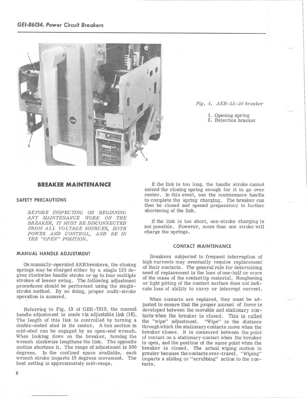
Fig. 4.
event, use the maintenance
spring charging.
AKR-SA-30
1.
Opening
2.
Rejection
enough
for
preparatory
one-stroke
spring
bracket
stroke cannot
it to
The breaker can
to further
charging
one stroke will
interruption
eventually require
generalrule
The
the loss
is
the contact
to carry
surface does not
or interrupt
proper
movable
the
closed.
"Wipe"
It is measured
contact when the
of the same point
actual wiping motion
the contacts
or
"scrubbing"
over-travel.
ofone-haLf or more
a:nount
and
replacement
for
determining
they
must be ad-
of
stahonary
This
is called
the distance
is
move when
between
action to the
the
when the
"Wiping"
bt,eaher
go
over
handle
indi-
current.
force
con-
the
point
breaker
is
con-
is
of
is
Page 7
Power
Circuil Breokers,
GEI-86134
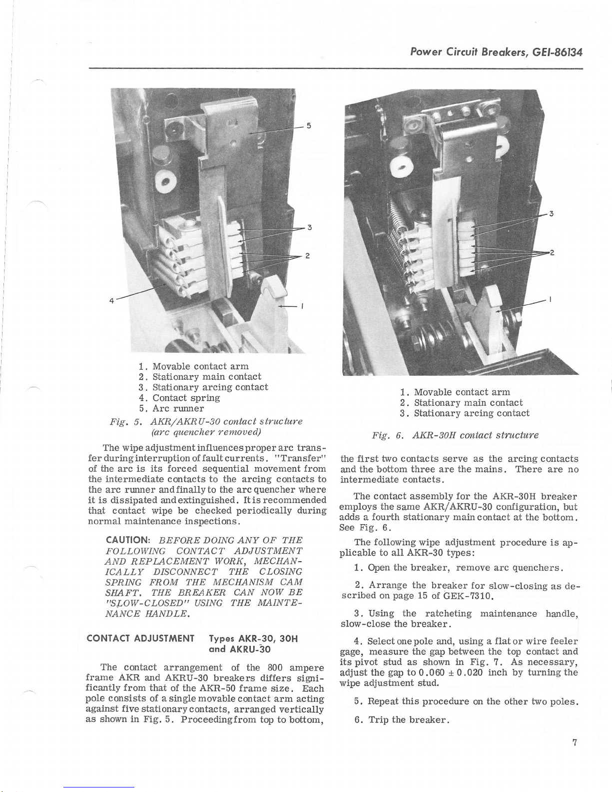
Movable contact arm
1.
2. Stationary
Stationary arcing
3.
4.
Contact
main contact
contact
spring
5. Arc runner
Fig.
The wipe adjustment influence s
fer during
the
of
arc is its
the intermediate contacts
the
arc runner andfinallyto the arcquencher
dissipated
it is
that contact wipe be
normal maintenance
CAUTION:
FOLLOWING
AND
ICALLY
SPI1/NG
SIIAFT.
,,SLOW-CLOSEDI'
NANCE HANDLE.
CONTACT
The
frame
ficantly
pole
against five
as shown
AKR
consists
AKR/AKRU-S} contact
5.
(arc quencher
interruption of
forced
andextinguished.
inspections.
BEFORE
remoued)
fault
currents
sequential
to
the arcing contacts to
checked
DOING ANY OF THE
CONTACT ADJUSTMENT
REPLACEMBNT
DISCONNECT THE CLOSING
WORK,
FROM THE MECHANISM
BREAKER CAN
THE
USING
ADJUSITilENT Types
contact
from
in Fig. 5.
arrangement
and AKRU-3O
that
of the AKR-50
of a
single
stationary
contacts,
Proceedingfrom
movable
THE
ond
AKRU-3O
of
breakers dilfers
proper
Itis recommended
periodically during
AKR-3O, 3OH
the 800
frame size.
contact arm
arranged vertically
structure
arc trans
Transfer'
.
"
movement from
where
MECHAN-
CAM
NOW BE
MAINTE-
ampere
signi-
Each
acting
top to
bottom,
1. Movable
2. Stationary
Stationary arcing
3.
Fig.
-
the first two contacts serve as
'
the bottom
and
intermediate
The contact assembly
employs
adds a
See
plicable
the
fourth stationarv main
Fig.
following
The
to all
1. Open
2.
Arrange
scribed
on
3. Using
slow-close the
4.
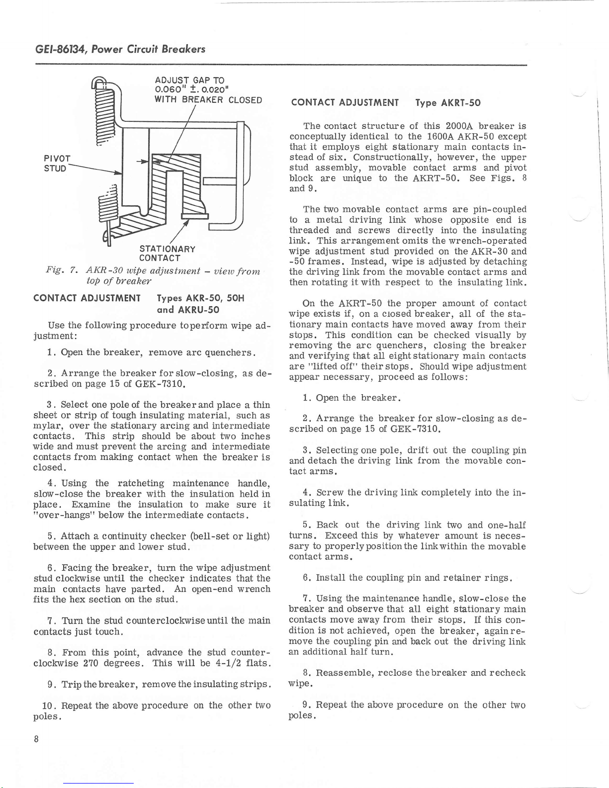
Se1ect one
gage,
measure the
pivot
its
adjust
wipe
the
adjustment stud.
5. Repeat this
Trip the
6.
AKR-S1H contact structure
6.
three
are
contacts.
AKR/AKRU-30
same
6.
wipe
AKR-30
the breaker, remove
the
page
stud as shown
gap
breaker for
15
of
the
ratcheting maintenance handle,
breaker.
pole
and,
gap
to
0.060 *
procedure
breaker.
contact
the mains.
for
adjustment
types:
GEK-?310.
using a flat or wire feeler
between
in Fig.
arm
main
contact
contact
the
arcing
the AKR-30H
configuration,
contact at the
procedure
arc
slow-closing
the top contact
As necessary,
?.
contacts
There are no
breaker
bottom.
quenchers.
0.020 inch by turning the
the other two
on
but
is
ap-
as de-
and
poles.
Page 8
GEI-86134,
Power Circuit
Breokers
ADJUST
0.060"
WITH
PIVOT
STUD
STATIONARY
CONTACT
Fig.
7. AKR-30
top
CONTACT ADJUSTMENT Types AKR-SO, sOH
Use the
justment:
1.
follorving procedure
Open the breaker,
wipe
of breaker
adjustment
qnd
remove arc
2. Arrange the breaker forslow-closing,
page
scribed on
Select one
3.
sheet or
myl.ar,
strip of
over
contacts.
wide and must
contacts from making contact
closed.
4.
Using
slow-close the breaker with the insulation held in
place.
"over-hangs"
Examine
5. Atiach
between
stud
main
the upper
Facing the
6.
clockwise until the checker
contacts
fits the hex section on
?. Turn
contacts
clockwise 270
just
From this
8.
Trip the breaker,
9.
15
of
GEK-7310.
pole
tough
the
stationary arcing and
This strip
prevent
the
of
breakerand
insulating
should be about
the
arcing and intermediate
the ratcheting maintenance
the
insulation to make
the intermediate
below
continuity
a
have
the
stud
touch.
degrees.
and
breaker,
point,
checker
lower stud.
turn
parted. An
the
stud.
counterclockwiseuntil
advance the stud
This will be
remove the insulating strips.
GAP TO
o.oeo'
t.
BREAKER
AKRU-SO
toper{orm
material,
when
CLOSED
uieoo
-
quenchers.
the
from
wipe ad-
as de-
place
such
intermediate
two
inches
breaker is
handle,
a
thin
sure it
contacts
(bell-set
the wipe adjustment
indicates
open-end
.
light)
or
that the
wrench
the main
counter-
4-1/2 flats.
CONTACT
The contact structure of this 2000A
conceptually identical to the
that it
stead of six.
stud
block
9.
and
The
to
a
threaded
ADJUST|YIENT
employs
assembly,
are
two movable
eight stationary main contacts in-
Constructionally,
movable
unique to the
metal driving
screws
and
link. This arrangement omits
wipe
adjustment
frames.
-50
the
driving link
then rotating it
the
On
wipe exists if
tionary main contacts have moved
stops.
removing the
verifying
and
are
"lifted
appear
1.
as
2.
scribed on
3.
detach the drivinE
and
tact
4.
sulating
5.
turns.
sary
contact
AKRT-50
This
necessary,
Open
Arrange the breaker for
Selecting one
arms.
Screw
link.
Back out
Exceed this by whatever
properlypositionthe
to
arms.
6. Install the coupling
?.
Using
breaker
contacts move
dition is
move the
an additional half
wipe.
and observe
not
coupling
8.
Reassemble,
stud
Instead,
from the
respect to the insulating
with
closed
on a
,
condition can be checked visually by
quenchers,
arc
that
all
their
off"
stops.
proceed
the breaker.
page
15 of
pole,
the driving link completely into the
the driving
the maintenance handle,
from
away
achieved, open the
pin
turn.
reclose thebreaker
lype
AKRT-50
breaker
1600A
AKR-50
however,
the upper
contact arms and
AKRT-50.
contact arms are
link whose
directly
the
provided
wipe is
movable contact
proper
the
on
adjusted
breaker,
See Figs.
pin-coupled
opposite
the insulating
into
wrench-operated
the
AKR-30
by detaching
arms and
amount of
of the sta-
aII
from their
away
closing the breaker
eightstationary
Should wipe adjustment
follows:
as
GEK-7310.
dri-ft
from the movable con-
link
tink two
main
slow-closing as
the
out
coupling
and one-half
amount
is neces-
linkwithin the movable
pin
and retainer
that
eight stationary main
all
their stops.
breaker,
and back out the driving
rings.
slow-close the
this
If
againre-
and
is
except
pivot
8
end is
and
link.
contact
contacts
de-
pin
in-
con-
link
recheck
Repeatthe above
10.
poles.
8
procedure
on
the
other
two
9.
poles.
Repeat
the
above
procedure
on
the
other two
Page 9
Power
Circuif
Breokers,
GEI-86134
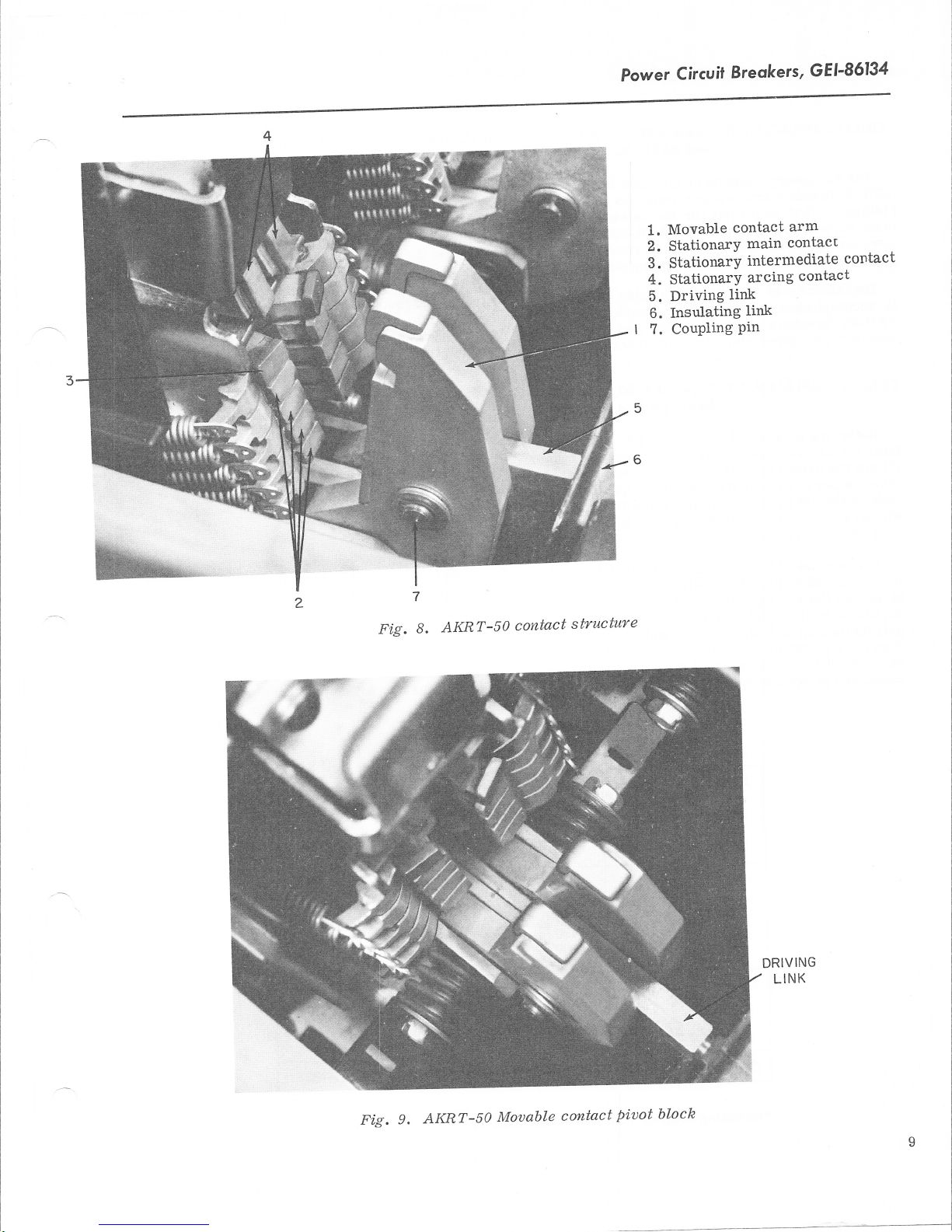
Fi,g.
7
AKRT-5)
8.
contact
structure
Movable
1.
StationarY
2.
3. Stationary
4. StationarY
5. Driving
Insulating
6.
I 7. CouPling
contact
arm
contact
main
intermediate
arcing
link
link
Pin
contact
contact
Fig.
AKRT-|7
9.
Mouable
contact
piuot
DRIVING
LINK
bloch
Page 10
GEI-86134, Power Circvil Breokers
CONTACT
The
AKR-30
fashion
main
however,
runner
Replacement of
is
accomplished
AKR-50
coupling
CONTACT
Referring
tacts
(5)
andthe
bling, make sure that the
ends of
',vashers
screws are
Intermediate
moved
pieces
serting a spring
puII
Replace the contact by holding it in
end behind
engaging
REPIACEIVIENf Types
stationary contacts
breaker
to that
frames
employed for the intermediate
stationary contacts
necessary
it is
AKR-30, 3OH
ond
AKRU-3O
(arcing
and
are replaced in
the AKR-50.
of
to first remove the
by removing its three holding screws.
the
single movable
in
like marurer
breakers, i.e.,
pin, pivot pin,
REPTACEMENT Types AKR-SO,
to
(L)
are released by removing the
Fig. 17 of
arcingcontact
remove
etc.,
AKRU-50
pivot (6).
employed for the
described
as
GEK-?310,
insulating spacers on
the arcing
(B)
replaced.
contact
under the
(2)
disconnecting their
by
on the
springs
puller.
the spring and lift it off
the
contact stop) while extending and
the
spring on
pin (7)
and the insulating
lower arc runner
main
and
contacts
springs. The end
(9)
have
While holding the contact,
the
small hole for
a
the
end of
end. A suitable
outer
mains)of the
identical
and
do
To
so,
arc
contact
replace
and
50H,
ond
AKRT-SO
arcing
arc
When reassem-
(3)
arm
the
below.
con-
runner
the
fastening
re-
are
in-
the
contact.
position
(inner
puller
end of a
by drifting
sulated coupling
are
tainer
can be fashioned
length
The
two movable contact
needed to
on
of. 1/76-tnch diameter
pin
out
remove and
the
end of
(10)
(11).
the pin.
by forming
arms
connecting
Right angle tru-arc pliers
replace the
Next, remove the fastening
pivot
springs
and
pin
from the
replacing the arms ensure that
and washers
Tighten
AKRU-3O ond
the
Except
for
returned totheir
are
two
bolts in the contact
-50 FUSED BREAKERS
the
open
fuse
integrally-mounted fuses
AKRU-30 and
fused
AKR-30
devices
Fuse Sizes
are
ond Mounting
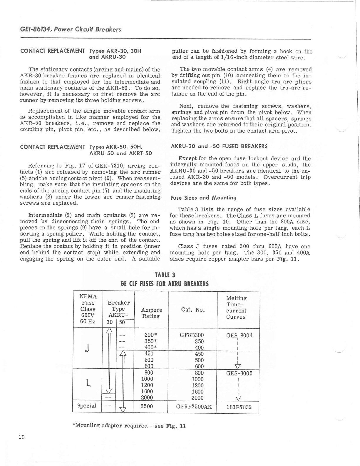
Table 3 lists
for thesebreakers.
as shown
which has
fuse
Class J
mounting hole
in
a
tang has
breakers
-50
and
the
-50
same
for
the range
TheClass L
Fig. 10.
two
holes sized
per
mounting
targ. The 300, 350
single
fuses rated
models.
both types.
Other
300 thru 6004.
sizes require copper adapter bars
pivot
all spacers, springs
lockout device
on the
identical to the
are
fuse
of
than the
hole
for
one-half
a hook
steel
(4)
are removed
them to
on the
wire.
the in-
tru-arc
screws, washers,
below. When
original
arm
position.
pivot.
and
upper studs,
un-
Overcurrent
sizes
fuses
are
800A
per
tang, each
inch bolts.
per
Fig.
trip
available
mounted
size,
have
one
400A
and
11.
re-
the
the
L
10
NEMA
Fuse
Class
600v
60
Hz
J
L
Special
xMounting
GT
Breaker
Type
AKRU.
-5dl5o--
ii
L 2500
adapter
required
CIT
IABIE
TOR ATRU BREAI(ERS
rusTS
Ampere
Rating
300x
3 50*
400x
450
500
6no
800
1000
1200
1600
2000
-
see Fig.
3
Cat.
No.
GFSB3OO
350
400
450
500
600
800
.
1000
1200
1600
2000
GFgF2SOOAK
11
Melting
Tine-
current
Curves
8004
GES
I
I
I
V
GES-8005
I
I
I
I
V
r.838?832
Page 11

IH
Ttbicat
on'AXnU-TT
mounting
and
fm
-50
Power
ttLttfuse
class
breakers
Circuit
Breokers,
GEI-86134
Fip.
"
11.
Mounting
on
fuses
300,
for
AKRU-3?
and
350
breaksrs
400A
Cl'ass
J
11
Page 12

GEI-86134,
Power
Circuit Breokers
la
1.
Special
2.
Disconnect
3.
Heat Sink
4.
Upper Barrier
5.
Primary
25004
Fuse
Key
Disconnect
Speciol 250OA
fuse
This
provides
Fuse
for
AKRU-SO
a meltingtime-current
acteristic that coordinates
Compared
fuse, the
its tangs
achieve
special
the
on
unique
fuses
(Refer
1.
from
the two keys
them upward
pull
tang.
physically
special
fuse
with a
is
are specially
the
required
primary
outboard tang
mounting
the following
to Fig.
Remove
the fuse
the disconnect assembly
12):
the
taag,
(2)
and
pole-to-pole
di
onnect assembly m
sc
of the fuse.
provisions,
procedure
primary
accomplishedby
their holding screw and
via
out.
After
NOTE: This remoual
disconnectts
Remove
2.
clamping
the upper
barrier
Fi.g. 12.
AKRU-|0
breaker with
char-
with 16004. trip devices.
25004 NEMA Class L
more
compact
configured
Considering their
when
should
disconnect
(shorter)
and offset
fuse
spacing; a
ounts
replacing
be
adhered
assembly
direcUy
these
first loosening
pulling
the keys
off
does
force
the
not disturb
adjustment,
(4)
.
are
end of
removed,
the fuse
the
to
to
;
special
4.
5.
6.
assembly
the
of
CAUTION:
FUSE
VIEW) OF THE BREAKER, NOTE PAR-
TICUIARLY THAT THIS
25004
Remove the heat
Remove the fuse.
[rstall the
fuse
new fuse
procedure.
fuse
and heat sirk are clean.
WHEN REPIACING THE
IN
THE LET-T POLE
(3).
sink
by reversing the dis-
Ensure that the mating
FUSE
MOUNTED DIFFERENTLY THAN THE
OTHER TWO FUS,DS. AS SHOWN
FIG. 14,
IS ROTATED 180 DEGREES ABOT]T
AXIS
SO
POSITIONED BENEATH THE BREAKER
STUD. fUtS
RESPECT
FIG. 13,
DOES
THE
SO THAT
NOT ALTER
PRIMARY
THIS
FOR
PHASE THE FUSE
THAT ITS INBOARD
rAtr,C tS OFFSET
TO THE
OPPOSITE
ROTATING
THE
POSITION
DISCONNECT.
THE FUSE
END
(FRONT
I7:S
TANG
WITH
(SEE
OF
faces
15
IN
IS
3 . Detach the inboard end
the
ing
socket with
turo
1/2 inch
a short extension
13 bolts. A
-
the
of
will
be required.
fuse
t2
by remov-
ratchet
and
Fuse Lockout Device
Open
Refer to
GEK-7310,
page
31.
Page 13

Power
Chcui|
Breokers, GEI-86134
13.
Fi.g.
FUSE TANGS
POSITIONED
Mounti.ngfor
AKRU-50
FRONT OF
ON TOP
breaksr
speci.al
BREAKER
2500Afuse
EE-W@I'
FUSE IS ROTATED
POSITION
TO
BENEATH
BREAKER
1.
2.
HEAT
3.
PRIMARY
ASSEMBLY
ISOO
TANG
BREAKER STUD
STUD
SINK
DISCONNECT
TANG
BOLT
IN USE
i
os
HOLES
PRIMARY DISCONNECT ASSEMBLY
MOUNTS
Fig. 14.
Plan
25004
25OOA. FUSE
CAT. NO.
GFgF25OO
DIRECTLY
uiew of
fuse
ON OUTBOARD
AKRU-S1
tang
osi)
AK
positi.ons
(SEE
FIG.I3
FUSE TANG
breahsr
)
showing
13
Page 14

GEI-86134,
Power Circuit
Breqkers
TYPE
powered
diagram
it
bas-is-T6T-6T6?6frrGnt
energ'y necessary to
electronic circuitry for
Their
(set-points)
ing
equipped rvith various combinations
Short Time, Instantaneous
elements. See Table
settings
equipped
pop-out,
across
with
from
second for short
andinstantaneous elements)
fault.
SST
OVERCURRENT
The
is
SST
trip
device
of Fig.
a
solid-state, direct-acting,
system.
16
and
the
comprises the following
Programmer
Unit
-
detection
trip
provides
the
the various trip
associated
the
on
pickup
located
are
application,
and
on
programmer
4
trip characteristics.
and
The
a
left
The latter is
programmer
SST
with trip indicators
mechanically-resettable
the top
ground
to
of
fault
right, the
programmer's
the
element
circuit
(actuated
omitted on
first is for
TRIP
Referring to the
photograph
individual
breaker.
timedelay
the lace
and
Ground Fault
for
available
units can
(targets).
employ three targets:
andthe
units
fault.
DEVICE
of Fig.
components:
the
comparison
delivers the
and
Contains
elements.
adjustments
plate.
units
Depend-
may
of Long Time,
ratings,
be optionally
plungers
These
Iocated
front.
overload, the
by the
short time
third for
without
self-
block
15,
the
be
trip
are
Units
ground
qround
Fig. 15. SST Programmer unit
target
Each
element
the
neglecting
of any
being
operates
popped
trip element or
reclosed.
Current
senE5i-66II(ef)-EETch
inputs necessa-ry
nal
sensor has
Each
justment
of the
rating. See Fig.
The SST
principle
the
rent in the three
tems)
On
trip
sensor
on a
programmer
Iong as
add
SST's equipped with
signal
in
series
ground
there is no
pops
to trip the breaker.
target must
to reset does not
Sensors
four taps which
trip
18.
Ground
Fault trip
that the
conductors
to
zero unless
is developed
with
differentia-ltransformer mounted
unit.
Its
ground
l4
when its
out
reset by hand.
be
aJfectnormal
prevent
each
-
supplies
to operate
device's
instantaneous
ground
Ground
associated
the breaker
pole
mounts a
the
the trip
provide
continuous
element operates
(four
on
current exists.
Fault,
by connecting each
companion
a
secondary
current.
primary
output
After
However,
operation
power
and
system.
field
ampere
vaLues of
4-wire
ground
the
winding
is zero so
trip
trip,
a
from
single
sig-
ad-
cur-
svs-
phase
in the
on
-
I
([$F$
r
I
)
Fig.
16.
SST Block
diagrant
-1
Page 15

Power
a
1.. :"
,*"ii
Circuit
Breokers,
GEI-86134
1. Flux shift
2.
Allen-head
3. Stud
4.
Connector
Current Sensor
Trip
Screws
Device
Fig. 17. AKR-54-30 breaker with
the
Application
of
Grorurd
wire systems with neutral
former requires
sensor
(Fig.
an additional,
inserted in
19)
its secondary is connected
ground
winding on
See Fig.
electrical
an
ing taps. Therefore, when
phase
correspondingly
FIux Shift Trip
the
2?.
sensors,
This
duplicate
those
positioned.
differential
"fourth-wire"
the
of
on the
Device
-
grounded
the
to
phase
taps
neutral sensor
a
element
Fault
at
separately
neutral
fourth
a
on
the trans-
mounted
conductor;
primary
tralsformer.
neutral sensor
sensor,
changed on
are
includ-
the
must
low-energy, electro-
m@n receipt of a trip signal
from the
actuating
programmer
the trip
sha-tt.
trips the
unit,
See Fig.
breaker by
22.
4-
is
be
5.
Tap Terminal Board
6. Programmer
7.
Clamp
8.
Sensor
All
mounted
located
are
grammer
mounted
ponents
disconnect
(Figs.
When
mounted in the
Bolt
SST
trip deuice
components except the
the
on
on
unit
the
on
interconnected
are
plugs,
25
and
used, the
switchgear.
automatically corurected
ary disconnect
Unit
Stud
circuitbreaker.
the
breaker's
the flux
and
breaker's
shown
as
26).
neutral sensor is
bus
drawout
In
blocks.
rl
I
i
neutral sensor
The
frame.
back
shift trip device
front
frame.
by
wiring
the cabling diagrams
on
cable compartment
or
construction,
to the
breaker via second-
See Fig. 20.
phase
sensors
The
These
harness
separately
of
its output is
are
pro-
are
com-
and
the
15
Page 16

GEI-86134,
Power
Circui|
Breokers
300
-
800
A
Fig.
Breaker
Type
AKR.30
AKR.5O
AKRT.SO
Pickup
o
Pickup
@
18. SST
Frrme
Size
(Amperes)
800
1600
2000
tolerance
tolerance
phase
X.
-Sensor
100, 150,225,
300,400,600,
300,400,
600,800,
+
is
97o
+
is
Wo
sensor
Trip
Rating
in
Amperes
Tap
z Seneor t
(
mp"t"
\
Trps
-or-
600,800
-or-
1200, 1600
800, 1200,
1600,2000
(See
with
)
/
300
800
pages
tnp board
TAB1E
SSI IRIP CHARACTIRISTICS
SSf PROGRAMMER
Long
Time
ria<5(-t
(':ff")
.6,.7, .8,
.9, 1.0,
1.1(X)
28,29
@
@
and
Time
)
Delav
Band
(Seconds)
Maximum
Intermed.
Minimum
Time
detay shown
Time delay
30 for
applicable
@
22
10
4
shown
4
Short
Pickup
o.
(*:'l'i")
3,4,6,
(L)
6,
81 10
---or-
L.75,2,
2.25,2.5,
(L)
3,4
at
60@o of long
at lower
time-cunent
Fig. 19.
ADJUSTMET|T
Time
Time
Delav
Band-@
(Seconds)
Maximum
0.35
Inrcrmed.
0.21
Minimum
0.095
time
limit
of band.
curves)
-
300
loo
SST
Neutral sensors
RANCE
fnstantaneous
Pickuo
@'
(':Tf*)
4,5,6,
10, 12
setting
(L)
8,
pickup
A
(Set
/
\
.2,.25,.3,
(6L),
Points)
,4, .5,.6,
.25,.3,.4,
GROIjND
Pickuo
-
1t\
g,/
Multipte\
of X
/
1.0,
.8,
(X)
1.2
.5, .6,
(X)
.7
.4, .5,
(X)
.6
at lower limit
FAULT
Time
Delav
Band-@
(Seconds)
0.30
Intermed.
0.165
Minimum
0.065
of
band.
16
Page 17

Power
Circui|
IROUBTESHOOTING
malfunctioning
When
troubleshooting
in
and
AS:
power system
its
to
is
for abnormal
Breakers,
is suspected,
examine
the circuit
GEI-J6134
first
the
breaker
conditions
step
such
REAR
AKR
VIEW
-50
trip sha-ft.
its
TAPS
ADJUST
KNOBS
to
by
voltage
to over-
to
due
ON
circuit
the
from
the trip
either of
tests
on
test
proper response
Breaker
a)
currents
Breaker
b)
mechanical
Inadvertent
c)
WARNING:
THE
THE
tripping
or
remaining
CURRENT
PROGRAMMER
WHILE THE
CURRENT.
it has been
Once
-
BREAKEFI.
MOUNTED
breaker
test
device
two
the
set.
can beopenedand
position,
proper.
methods:
1.
Conduct
attention
Testing
high-current, single-phase
breaker using a
in
incipient
ground faults.
in
a
interference
trip
shunt
DO NOT
activations.
CHANGE
SENSOES
UNIT
BREAKER
established
closednormally
can be directed
performed
is
high current-low
trip-free state
along
Oft
SET
15 CARRYING
that the
Fig.
20. Neutral
blocks
sensor
EQUIPMENT.
MOUNTED
secondary
disconnect
NOTE: For
cinl
cormections mustbe
breakers equippedwith
single
-phase
transformer
"ground
the
by
(a)
fault't
breaker.
testing
series, or
(b)
Using the
sho?,m
as
test cable energizes
windings
former
parallel
ary
output is always zero.
2.
portable
applicable
tion
Book
next
the
Test
page.
components
Test
Set
procedures
test
GEK-64454 and are
these single-phase
employedfor
Ground Fault. Any
i;nfut to the
will
output signal
This
two
Ground Fault Defeat
in
ground
generate
can
be nullified either
poles
Fig.
of the breaker in
28. This
of the differential
in a self-cancelling,
connection so that i.ts second-
the
of
Type TAK-TSI
a-re
tests, spe-
SST
differential
zmwanted
cn
which utill trip
Cable
special
pri.mary
the
all
trans
series-
system using
SST
(Fig.
21).
detailed in
summarized on the
Instruc-
-
The
t7
Page 18

GEI-86134, Power
Circuit Breokers
Fig.
USING THE
The TAK-TSI
designed
acteristics and
various
the
Flux-Shift
in
addition,
phase
the
WARNING:
TEST SET TO THE BREAKER
VICE SYSTEM,
CIRCUIT BREAKER 15
DISCONNECTED
SOURCE. ON
RACK THE BREAKER TO ITS
NECTED POSITION. VERIFY I:HAT
BREAKER IS TRIPPED.
Either of
rrArt
-
SST TEST
sET
Test
Set
is
a
for field-checking the time-current char-
pickup
trip elements.
Trip
includes means for continuity
sensors.
BEFORE CONNECTING THE
It
Device
calibration
can
to trip
ENSURE
FROM ITS POWER
DRAWOUT EQUIPMENT,
two test modes may
Programmer
Unit
be employed:
Only.
conduct@
from the
attached
moved from
breaker. During test, the
to the
breaker
or
may
it.
SST/ECS test set,
21,
portable
verify
instrument
the
of
the ability of
SST's
the breaker
checking
DE-
TRIP
THAT THE
COMPLETELY
DISCON-
THE
These
unit
be completely re-
tests
disconnected
unit can remain
andr
are
cat. no.
CAUTION:
T//,RNESS CONNECTOR FROM
GRAMMER
/S
CURRENT.
TAK-TSI
NEVER
UNIT ON A BREAKER THAT
ENERGIZED
THIS
AND
WILL
THE CURRENT S.ANSORS,
DANGEROUS AND
AGES TO
scope:
Test
1.
Verify
pickup
on
rrBrt
calibration
2.
Verify operation of
programmer
Complete
-
DEVELOP.
the
time-current
the various trip
of
units so equipped.
Trip Device System. For these
tests,
the breaker
scope:
Test
1.
A11
"A"
vision
output
veri-fy its
breaker.
does
test instructions
for
optionally switching the
to
activate
operation by
2.
Check
the event that
In
perform
not
connected
and
tests
phase
GEK-64454.
previously
the
Flux-Shift
sensor continuity.
component of the
any
within the
DISENGAGE THE
THE PRO-
CARRYING LOAD
OPEN-CIRCUIT
ALLOWING
DAMAGING VOLT-
characteristics
elements.
the
target indicators
SST
to
its
wirins
described,
programmer's
mounted
harness.
plus
Trip Device
physicaliy
limits
it should
tripping the
SST
prescribed
replaced.
be
and
on
pro-
and
system
in
18
Page 19

Power
Circuit
Breakers,
GEI'86134
TRIPPING
FALSE
GROUND
When
equipped
FAULI
nuisance
with
p"onalte cause
slgnaf .
26, each
primary
indicated
As
phase
winding
lransformer.
circuits,
Ioad
to zero
add
current
This
sensors
sensor
one
If
rating or
ent
transformer
breaker.
sensor
signal.
trip
nuisanc
If
whose SST
satisfactory
the sensors
Set,
closely
breaker
and
have
can
Similarly,
the
and
e
components
performance
scrutinized. After
from all
- BREAKERS
tripping
the
Ground
is the existence
by the
sensor
Under
the currents
sum
the
di-ffers
wrong
programmer
tripping
is connected
the
on
no-fault
ground
no
will
same
from
tap setting),
produce
is encountered
have
their connections
and
power
Ground
be
electricaL
output
discontinuity
sources,
EQUIPPED
occurs
Fault
of a
cabling
conditions
in these
signal
zero
WITH
on
element,
trip
false
diagram
in series
differential
Fault
on
three
is developed.
i-t
only
breakers
"ground"
Fig.
of
with a
3-wire
windings
three
all
characteristics.
the others
(i.
the
sufficient
unit can cause
on any
previously demonstrated
the
via
TAK-TS1
disconnecting
differ-
e.,
dilferential
to trip
between
a
breal<er
should
the
any
false
Test
the
a
e) If
REPTACEMENT
be
Referring
current sensors is
condary
for
disconnect
continuity
neutral secondary
through to the
(terminals
(3)
the breal<er's
If
the
supply
sor must have
to the source.
(4)
Ensure
carrying only
ciated
(neutral
precedingstepsfail
the
Iem, then the
measured.
sors
are electrically
tap resistances
to
L and
source, then the neutral
that the
with the breaker's load current
not shared
sensor resistances should be
Since
OF CURRENT
Fig.
17,
accomplished as
block.
Also
from the breaker-mounted
discormect block
female harness connector
N).
lower
its
that
the
should
remova!
studs connect
LOAD
neutral
end connected
eonductor
neutral current
with other
toidenti-ty the
phase
identical,
closely agree.
SENSORS
loads).
neutral sen-
and
their
individuat
of
follows:
tap-to-
check
to
sen-
is
asso-
prob-
SST
a)
Check
type
b) Ensure
sensors
c)
Verify
sensors
that
(ampere
that the
are
that
meet
cated by
to
wire
d)
On Ground
COMMON,
loads, check that
erly connected
particular,
In
(1)
Verify
same rating
sensors.
(2)
Check
sensor
all
range).
phase
sensors
tap settings on all
identical.
the
harness
polarity
the
the
cabling
Fault
(see
that
the neutral
and
continuity
its equipment-mounted
ald
diagram, i.e., white
wire
black
breakers serving 4-wire
the neutral
cabling
tap
setting
between
the same
are
3-phase
connections
constraints
to
TAP.
sensor is
diagramFig.
sensor has
the
as
tlle neutral
to the
indi-
prop-
2?).
the
phase
se-
a) Disconnect
terminal
necessary.
the
breaker
b)
the rear
At
Allen
connector
Loosen
c)
stud
connector.
tap terminal
NOTE:
to adjacentaccessories,
be
necessary to
(8)
also.
holdi,ng bolts, accessible
the
breaker
the
breaker
board
head
(3)
the clamping
(5),
Unfastenthe terminal
base.
the
of
screws
from
Lift
board.
prouide
To
Do
more working
remoae the sensor stud
this
(see
Fig. 20).
harness from the tap
removing cable
breaker,
(2)
the contact
bolt
out
by remouing
remove
to
separate the
pivot
(7)
the
i,t
may sometimes
remove
and
sensor
clearance
its
the rear of
from
ties
board
the two
block.
and its
foar
as
from
stud
the
19
Page 20

GEI-86134,
Power Circuit
BREAKER
I
\
CLOSED POSITION
Breqkers
\
/
ACTUATOR
Fig.
FLUX SHIFT TRIP DEVICE
mounting arrangement
The
illustrated in Figs. 22 and23.
actuator
located
is coupled to
driven
solenoid whose
its
in
net. In
So
the
by
normal
this
long
as
state
the
on
the
breaker's trip
actuator
armature
(Reset)
the
position
the
spring is compressed.
acfuator
undersideof the front frame
sition, the breaker can be closed
at will.
ally
ceives
actuator
the magnet,
ature;
paddle,
this drives the trip
the
As
turned to its
driven by
permanent
readiness for
in
The
However,
bip signal from the
a
is energized
allowing
tripping the
breaker
normal
crank on thebreaker's main sha-ft.
a
magnet
the next trip signal.
trip device requires
thetrip rod length. As
between the trip rod
ance
paddle
is
gaged
by
when a closed breaker re-
and
the spring to release the
breaker.
opens,
(Reset) position
again
shown
0.125
a
of
arm.
is spring-loaded
by
remains inthe
programmer
its solenoid flux
rod
against
the
actuator arm
the
holds
only one
in
end
inch diameter rod.
22. Flux shi.ft trip deuice and operating
li.nkages
just
this component
electromagnetic
An
via
shaft
The
permanent
a
and opened
trip rod
a
acfuator
and
Reset
norm-
unit, the
opposes
the trip
via linkage
armature
captive
is
held
mag-
arm-
shaft
is
The
po-
re-
gap
the breaker
its Reset
is
adjuster
retighten the
a
The
requires
case of malfunction,
should be replaced.
connection
mended that the breaker harness
convenient
spliced
breaker harness and
directly from the female
the breaker harness.
of
tool
Cat.
0. 125
to
position.
end
actuator
no
point
thereto.
No.
CAUTION:
SST TRIP DEVICE
INOPERATIVE
BREAKER
OUT
BENEFIT
TECTION, THE
METHOD /S TO
BY
ROD
FULLY
ACTUATION
PADDLE,
Fig.
and
adjustment
24,
the
clear-
the trip
-
shaft
Ad-
inch+ 0. 015 inch.
and restore
until
jam
nut.
is
maintenance
to
the replacement unit, it
the breaker mechanism to
Loosen the
proper gap
the
a sealed,
factory-set
or
the
complete actuator
When
To
adjust,
jam
nut, rotate the
is attained, then
field
adjustment. In
making
the electrical
be cut
the
and
An
305183 is required for
IN
TO
TURNING ITS ADJUSTEN END
CLOCKWISE.
new actuator leads
afternate
remove the
methodis to untie the
old
actuator
connector on
AMP
However.
AMP
this method.
THE EVENT
MUST BE
TO
CARRY CURNENT WITH-
OF OVERCURRENT
SHORTEN THE TRIP
OF THE
TIIAT THE
RENDERED
ALLOW THE
RECOMMENDED
THIS PREVENTS
TRIP SHAFT
open
device
is
extraction
recom-
at
solder-
the end
PRO-
and
unit
some
leads
20
Page 21

_t\tr1
Power
Circuit
Breokers,
GEr-86134
Bottom
1.
Acfuator
2.
Trip rod
3.
Trip
o
ora.
tzs"
ROD
?
view
adjuster
paddle
Fig. 23. Flux
end
shift trip
deui.ce
components
Fig.
24.
Top
4.
Trip shaft
5.
Actuator
6.
Reset
Trip
view
linkage
rod
adjustment
arm
2t
Page 22

GEI-86134,
Power
Circuit
Breokers
FLUX
SHIF
TRIP DEVICE
WHITE
Fi.g.
Cabling Diagram
25.
ground
fault
HARNESS
CONNECTOR
(AMP
201298-1
SS? nithout
-
PROGRAMMER
CONNECTOR
)
(AMP
201297-1
--_-J
)
Ir
t)-
IF
IF
IF
IL
Fig.
26,
22
Cabling
fault
Diagram
on
S-wire load
HARNESS
CONNECTOR
(AMP
201298-1
SS"
-
)
PROGRAMMER
,A'8Jlf,";?I,
ground
with
I
I
t_______.!
Page 23

Power
Circuit
Breokers,
GEI-86134
FLUX SHIFT
DEVICE
TRIP
li
.A
PROGRAMMER
UNIT
r----l
(48V.
dc)
(TO
SCR
ANODE)
s
F
F
F
F
)--
F
F
L
ll
{i
t______..i
PROGRAMMER
CONNECTOR
(AMP
201297-1)
ground
4.WIRE
LOAD
Fi.g. 27. Cabling
on
fault
Diagvam
4-wire
CONNECTOR
(AMP
-
load
SS?
201298-1)
uti.th
BREAKER
HARNESS
CONNECTOR
CURRENT:":\
SENSORS
oA!-f€-l-1
'----ro
gj--o_f<
B
o
L______+_{.H
g-+-+-3
oc
+
>Fl|-*r<
)L'ii-ofi
.
NEUTRAL
SENSoR
DIScoNNEcT
I
I
i
L_t
r\r
I a--t----z
I
o_5
, d-J--J
"I
H
Gq
Fig.28.
GROUND FAULT
B
E-
A
c ,l
U
%
H-
K.
L.
N
M
\
D
R.
MALE
END
Cabling
Cable
and
single-phase,
CAT. NO.
DEFEAT
TGFD
H
il
I fr f
J
'1
tl
J
II
ffi
lr
diagram
inserted
SST Programmer
L
r
L
FEMALE
with
between
high
current
#
>5
END
CABLE
B
E
-A
D
H
^L
N
M
-P
R
Ground
breaher
Unit
PROGRAMMER
UNIT
l------r
r-1
ffr
ffr
# hll
4++---Jlll
<-t--F
e-+-o+--Jlllf
e+--o-f
++++---_-Jlllt
fft-rlll
ffJ---Jlll
ff
+o
<--l-{
L_t
Fault
lnrness
use
-
for
low
-
^lll.
"illf
L__
Defeat
during
uoltage
|
I
testing.
ANY
SST
PROGRAMMER
UNIT
WITH
GROUND
ELEMENT
FAULT
23
Page 24

GEI-86134,
Power
Circuit
Breokers
TYPE
powered
cates SST except for
of
Long Time,
elements
available.
able.
ECg
OVERCURRENT
The ECS is
a
trip device
1.
Programmer units
Short Time
only. The
2.
Fau1t
indicators
solid-state,
3. Phase sensors
Table
rating.
the tabulated
range
is no
operates and
This
ponent
formance
reliability
same
single-phase, high
those employingthe
Fault
5,
each sensor has
different sensor is
A
ampere
as SST.
4.
Ground
In
all
Neutral
other
s enso rs
Fault
respects
can be treated identically to
includes circuitry,
location,
programmer
characteristics,
the flux
and
troubleshooting
procedures,
test
TRIP
DEVICE
direct-acting,
system
the following:
Ground
(trip
are
ratings,
ar
function.
that
essentiatly
are limited
and Instantaneous trip
targets)
not tapped.
only a
e not r equir ed
the ECS trip device system
to
combinations
Fault
element is not
not
are
listed in
As
single
available for each
which span the same
ampere
becaus e
size, construction,
unit
operatin
shift trip device.
test
and
points, per-
set
g
r
ange,
quality,
Use
procedures
current-low voltage tests
TAK-TS1 Test Set. Thei
of eourse, do not
apply.
self-
dupli-
avail-
ther
SST.
com-
the
for
or
Ground
of
,3"
:::--
e
Fig.
29. ECS
*
Programmer
unit
24
Fig.
"Ftux sHtFI"
TRIP
c0[.
30. ECS
Block
PxocBtLMEjugrJ
diagram
Page 25

Power
Circuit
Breokers,
GEI-86134
Breaker
Type
AKR.3O
AKR.50
AKRT.SO
ri)
Pickup
\J/
Pickup tolerance
@
Frame
Size
(Amperes)
800
1600
2000
tolerance
Fi.g.
X
=Sensor
100,
300,400,
800,
is+ 9Vo
+
is
10Vo
31.
Rating
Trip
=
Amperes
in
Rating
Sensor
/
(amp"'e
\
Rating
150,
300,400,
800
600,
1200,
1200,
800,
2000
1600,
ECS current
breaker
IRIP
TCS
Pickg(=L)
\
)
Muiiiple
/
/
225,
600,
1600
ofX
\
.6,
q
1.1(X)
@
@
(See page 27
sensors
5
IABI.I
CHARACITRISIICS
PROGRAMMER
ECS
Time
Long
Time
Delav
Band
\
(Seconds)
/
Maximum
22
.7, .8,
time
lower limit
fim"
Intermed.
delay
delay
10
Minimum
^
shown
band.
of
shown
10
for time-current
AKRU-44-30
on
ADJUSTMENT
Pickup
@
Multiple
/
@
\
ofl, /
3,4,5,
8,
6,
-or-
7.75,2,
2.25,2.5,
3,4
of
6007o
at
at lower
limit
cuwes)
Short
10
(L)
long
\
(L)
of band.
RANGE
Time
Time
Delav
Band
(Seconds)
Maximum
0.35
Intermed.
o.2L
Minimum
0.095
pickup
time
(Set
@
Points)
Instantaneous
Pickup
/O\
Multiple
1
\ ofl',
4,5,6,
12
10,
8,
(6L),
setting
-
\
/
(L)
at
25
Page 26

GEI-86134,
Power
Circuif
Breokers
Fig.
32.
LOAD
Cabling
SHIFT
FLUX
DEVICE
TRIP
HARNESS
CONNECTOR
(AMP
201298-1)
diagramfor
ECS
PROGRAMMER
UNIT
l-----l
(48V. dc)
(TO
ANODE)
t_______.!
PROGRAMMER
CONNECTOR
(AMP
201297-1)
Deui'ce
Trip
SCR
26
Fig.
ECS current
33.
sensor
Page 27

I
IFffi
6
I
g
=
E
tol
.! .l
s
s
l0
s
!0
s
s
20
.t .l
Power
(|',)
toNG'rlME
MUTflPtES
ll!
|
7
|
t
OF
r0sto
{
$
PlcKuP
F
sssFEs!
F
Circuit
Breokers,
;
GEI'86134
glFlll
3
tu
M
to
tI
0
s
{d
il
lr.
to
s
u
t0
s
!0
{
x
20
l0
I
I
1
a
.o
.s
.g
.o
,02
AKR-30
AKR.5o
AKRT-5o
AK-75
AKR-75
AK/AKR-lOO
GEITERAt
X
@
irnrr
Cornnl
=
100,150,225,300,400,600'800
300,400,600,800,1200,1600
8oo,1200,1600,2000
1200,
l2oo,1600,2000,3000'3200
l600,
rtlcrntc
Roling
1600,2000'
3000'
2000,
(AnP.t
3000
4000
a
t
.!
.l
.7
.a
.l
.t
.2
o
,
o
li=
::I
H
.0t
.q
.u
.c
glFsll
r
r
'
,2 nuxi',..
g
;
ir optionol
c. e
":i:'i:
r' s.
s.
ot
Inrlohiontoer
Hil't':l:
t to
'uript'r
'Ionenim'
o{
p''tup
27
!0 40t0
{
IoNG-TIME
MUTTIPLES
l-r/lxn
!)
ond
OF
cud'r oDelv
"'lv
'--"
+
lo
2m
PowER
6r s/& H'rt
't
7OC
low-volrAcE
t ong-time-deloy,
In-stontoneour'fime'current
Fron
-
PICKUP
clRculr
shoil-timedeloy
$/@
P.oerqin..
H'rh
Curuer
Ambi.nt
IVSION,
t
(L)
BREAKERS
PIAINVILLE,
3!l!!!
ShorFlim.
NOIE:
,';i*-
[i"i1'S';;1
T#1'J.l'i;::111,'lT.";rg
l#i:::::l':
{h''9
{ni'g
rrxt DTLAY uNot
CONN
(L'
(L)
'Ll
T'::
06062
drlov
''$*'"lll':'f#:
,o r
ii'
Page 28

GEI-86134,
Power
Circuit
Breokers
lomffi
!00
7m
t00
5@
m
300
?m
o50
z
Qo
z
U
3ro
F
LONG-T|ME PICKUP
t0
OF
{ ,o o
rororoE
MUTTTPLES
.t .l
.l
-a
{
(r)
F TFEFESE
F
s I
sgFEE!
toil
t0
am
76
m
ls
s
t6
26
tm
n
s
!0
70
80
30
t0
t0
t!
l0
I
{
20
28
-01
.0!
.07
.06
.04
.0t
.02
GE1{ERAr
X
scnror Topr
-Cu,rcnt
AK-r5 70,
AK.zs 70. 100,150,225
iff^.*%,.
aKT/AKRT.5o
AK 75 1200. 1600,
AKR.75
AK/AKR-r00 r600.
)00, t50, 225
133:
800.
1200. 1600, 2000,3200
rrrCrnrc
@
(Anperer)
or 2oo,3oo.4oo.600
l3?3i,?oo3:i
r200, r600,2000
2000. 3000. 4000
ioo3..ioo3.i!3aili.o
2000, 3000
GENERAL
20 to..to,,oto|orlg
MUT.TIPTES OF
AKIAKR
SS T'" s'LtD-sTATE
ond Insronroneous
CO, DISTR]BUTION
ELECTRIC
T.ONG.TTME PTCKUP
LOW.VOITAGE
long-time-deloy,
C!d.!
Fron
opply or 50/&
2C b +
70C P.osr.hm.r Ambi.nr
-
EGUIPMENT DIVISION,
POWER
CIRCUII
'vERcuRREr{rTRrp
Short-fime.deloy
Time-currenr
H.f
F
DE',rcE
curves
PtANVLLE,
g
EESFEtt
(r)
BREAKERS
CONN
ilcxut
totlli.:
(x) (s.ilingr
.hing
incr.o, lh. .onli^uour cur.nr
Shod'tm.: f.75, 2,
Longri6.
In.r.nt.r.or: a,
(t),
-xi.r
Plog.onnor
7, .1, .9, L0 I LI nulhpl.,
6.
high.r
2.75. 2.5, 3 A r.r
pi.lup
(tl. For
sin.s
5, 6, 3, l0 t 12 mllripl.r ol Loneii6.
For
H1otsr.rio.,
50
.d Si.dii'.: kr r.i r Min
06062
t t t tttttt
c c t c o cccc
t a I t tFatc
GES.6033B
Poinfi
sal
.u....i r.nior l.p
ol
IOO%
rh.
lh.n
ot
Not 2.
a,
3,
op.ronon,
I'06. ri'. do not
I l0 huhi9l.r
5, 6, I
n. Nol.
rolinql.
50 ar
-.
o
I
g
.04
g
=
.07
.il
=
.0t
.g
.01
.e
ol
2.
pi.rup
Page 29

MUTTTPTES
OF
CURnENT
SENSOR
TAP
(X)
Power
Circuit
Breokers,
GEt-86134
t0m
t00
t4
ts
mo
500
tn
H
to
t6
0
50
0
u
lm
s
s
t!
t0
o
2
o
g
30
z
u
20
=
l0
a
I
I
I
4
t
l0
s
s
t0
I
I
1
I
5
a
t
,l
.ot
.01
.0t
.0!
.01
,g
.0t
NOT[: alh
or
AK-r5
AK.25
AKR.3O
AK/AKR.5o
2-7E
I
I
wL. Grouid 3.nFr lap hud b. ct
pho3.
p,
t
!.nFr
cEt{ERAr
Currrnl
70. roo.
70, 100,
{3M)
@
IOO, I50, 225.300
400, 600,
3oo.
rrrcrntc
Topr
Scntor
l5o,2zs
150, 225 ot
8oo or 600.
rdh.
(AnPel€!)
2OO
or 300
GENERAT
TYPE
400,
300,
400' 600, 800
l2o0.
8oo
ETECTRIC
MurilprEs
I.OW.VOITAGE POWER
AKR
5ST'"tor,o.tTATE
Ground Trip
600
1600
,..,
CO, DSTRIBIJTION
oF CURRENT SENSOR TAP
EREAKERS
CIRCUIT
DIVISION,
DEvlcE
PLAINVLLE,
ovERcuRRE.{TTRtp
Time-current Curves
-:"#";?%:tr:3'.13*'il^*.,
EQUIPMENT
(X)
CONN
GES.6034A
Ground Fouh PickuD:
AK-15/25
AKR.30
AK/AKR-5o
Ground
06062
.5x,.6x,.8x, 1.0x. 1.5x,
.4x. .5x, .6x,
.25x,.3x,
Where
Fouh Doloy
Moximuh,
.8x.
.4x. .5x,.6x. A.7x
X
lensor
=
Eqndt:
Inlermediot€
& 2.0x
I .0x,
&
top
selling
& Minimum
l.2x
.t
.l
.t
.l
,a
.t
t
l!=
:::
.05
.(
.d
A
,
o
U
3
29
Page 30

GEI-86134,
t@
r0!
100
100
@
3S
2@
Power
Circui|
Breokers
MUITIPLES
OF
CURRENT
SENSOR
TAP
(X)
ro
I
I 0oo
900
!00
t00
800
t00
am
300
200
I
I
ilOTE: 4th wle
03
AKT/AKRT,5o 800,
AK 75
phdee
lenFr
GEr{ERAr
X = Cu.renl
Grcund senror
lop.
@
SenF lopr
rop BUn be
rrrcrnrc
(Amperer)
1200,
1600,
I 200, I 600, 2000, 3000
ffi
.one
tet
MULTIPIES
AK/AKR
2000
AKR-75 1200, 1600,2000,3200
AK/AKR.Ioo r600,2000.3000,4000
30
CURRENT SENSOR
OF
I.OW-VOLTAGE
55T'-
touo-tTATE
POWER
0vERcuRRENT
Ground Trip Time-curreni Curves
Curver opply ot 50/60 Heilt
t'om
ztr to +
-
Prosronme. Ambient
70C
CIRCUIT
TRrp DE',tcE
TAP
BREAKERS
(X)
AKT/AKRT-so .2x, .25x. .3x, .4x, .5x, & .6x
AK-75 .2x, .22x, .25x,.3x,
AKR-75
AX/AKR-100
Ground
.2x, .22x, .25x,.3x, .35x & .37x
.lgx, .2x, .22x, .25x, .27x & .3x
Where X
Foull Deloy Sonds
Moximum, Inlermediole &
=
sensor
.35x,
lop seltinq
Minimum
&.4x
Page 31

Page 32

rther
f u
For
or
call
General
Office
Sales
information
write
Electric
Your
.
or
local
' '
Distribution
EquiPment
41 Woodford
Plainville,
CT
Division
Avenue
06062
GEN
ERAt
@
ELEcTRIG
 Loading...