

Page 1
MAI NTE NANCE
MAN
UAL
t nc t
t
u de s
s u
ppte
ment8Fi#3;
POTVEN
TYPES
CIRCUIT
BNEAIIERS
AKR.3/3A-50
AND AKRU-3/3A-50
GEilERAr
@
ErECTRlC
Page 2
GENERAL
General
Breaker
Mounting
Fused Breakers.
Breaker
Breaker
DESCRIPTION. .
Types
Ratings
Description . .
CONTENTS
.
.
.
Page
3
3
3
4
4
4
4
RECEIVING, HANDLING, AND
Receiving
Storage
HandlinC . . .
and
BREAKER OPERATION
Putting the
Breaker in Service
Drawout Breakers
Breaker
Insertion
(Fig.
Breaker Withdrawal
Stationary Breakers
Pre-service
Operating
Manual Closing
Electrical
Openlng
the Breaker
the
Check
Breaker
Closing
Interlocks
Closing
Racking Mechanism
Optional
Accessories .
Shunt Trip
Undervoltage
Static
Electric
Spring Interlock
Interlocks
. .
Device
Time-delay
Lockout
Undervoltage
Device
Interlocks
Auxiliary Switch
BeII Alarm
BREAKER MAINTENANCE.
Safety
Precautions
General
Arranging the Breaker for
Slow Closing
Lubrication
Replacement
Mechanism
Mechanism
and Adjustment of Components
(Figs.
12, 13,
Replaeement
Latch Adjustment
Manual Handle
Adjustment
Contact Maintenance
Contact Replacement
(Fig.
Contact Adjustment
Components and Accessories
Auxiliary Switch
Trip
Shunt
Maintenance of
Electrical
Control
Bell Alarm/Lockout
Drawout
Mechanism
(Fig.
18)
and Undervoltage
Static Delay Device for Undervoltage
C omponents
FiS.
and
AKRU-50 Fused Breaker
Fuse Replacement
Fuse Lockout
Open
Power Sensor Overcument
Tripping
False
Testing
Replacement
Current
Magnetic Trip Device
Selective
Time-current
Tripping
Curves
Device
Caused
Sensors
Trip Device
by Faulty
(Figs.
STORAGE
3)
(Figs.
6A
(F'ig.
. . .
14)
and
(Figs.
Interlocks
17)
.
Device
26).
(Fig.
33
15
32)
Ground
and 38)
68).
and
8)
and
(Figs.
.
.
16)
.
.
and
. .
19
Fault Operation .
. .
Accessories
20).
and
. .
(Figs.
.
.
21
.
and
22)
. .
. . .
5
5
5
5
t
5
5
n
I
7
8
8
8
10
10
10
10
11
11
12
t2
13
13
13
l4
t4
15
15
15
15
16
16
.
.
16
18
19
19
19
19
20
2l
2t
22
24
25
27
28
29
29
31
31
34
34
34
36
36
3?138
Page 3
IOW-VOLTAGE
TypEs
AKR-3/3A-so
POWER
AND
CIRCUIT
AKRU_3
/ga-so
BREAKERS
Low-voltagepower
controlling
voltage
this
function,
loads
normal
the
more
overloads
The
breakers
protection
mizing
sons
who apply,
will
acquire
information
andprotecting
range
and
automatically
conditions
common
and
proper
is
a
personnel,
of
equipment
the knowledge
contained
(usually
they
undervoltages.
use,
prime
damage
use,
BREAKER
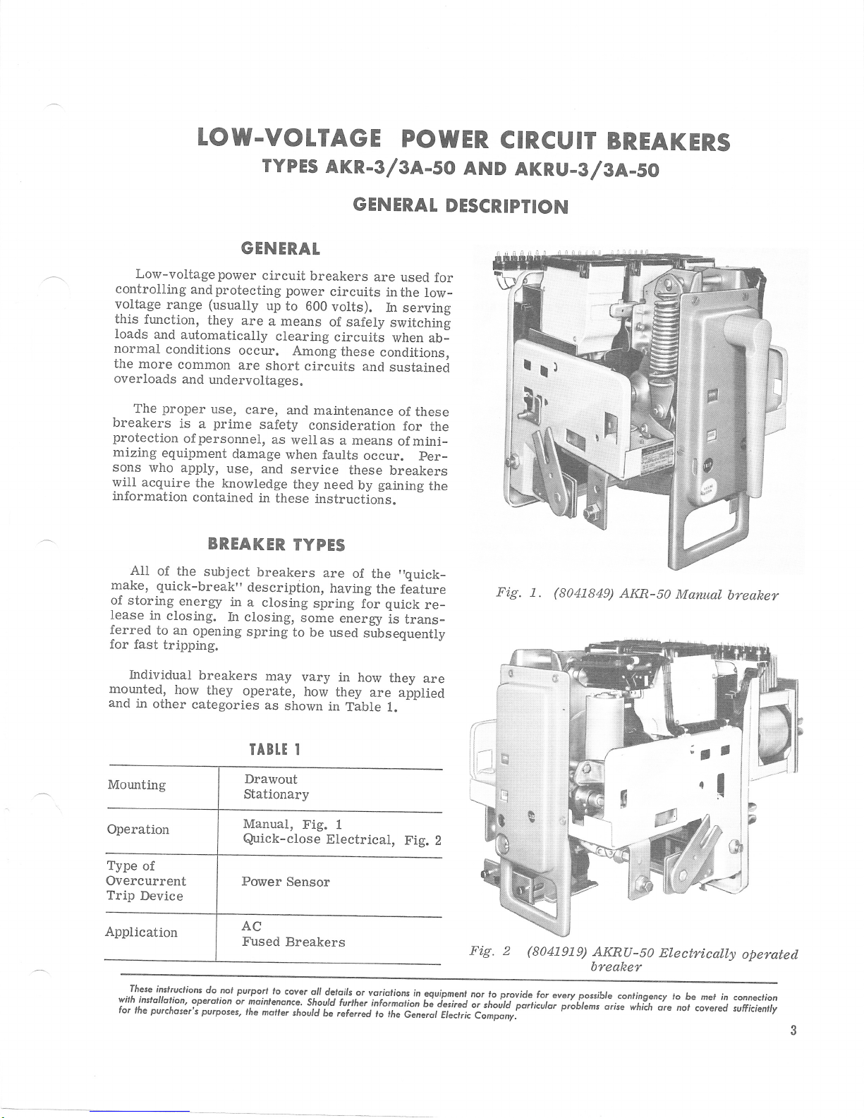
Ali
make, quick-break"
of the
of
storing
lease
in
ferred
for
to an
fast
subject
energy
closing.
opening
tripping.
in
In
GENERAT
circuit
power
up
to
are
a means
clearing
occur.
are
care,
Among
short
and
safety
as
wellas
when
and
service
they need
in
these
TYPES
breakers
descripiion,
a closing
closing,
spring
some
to be used
GENERAT
breakers
circuits
600
of safely
circuits
maintenance
consideration
faults
instructions.
are
having
spring
volts).
circuits
these
and
a means
occur.
these
by
of
the
for
energy
sJbsequenilv
are used
conditions,
gaining
the
for
inthe
low-
In servins
switchin[
when
ab-
sustained
of
these
for
the
mini_
of
per-
breakers
the
"quick_
feature
quick
re_
is trans-
DESCRIPTION
Fig.
(8041849)
1.
AKR-50
Manual
breaker
hdividual
morrnted,
and
in
other
Type
of
Overcurrent
Trip
Device
These
inslruclions
wilh
instollotion'
for
lhe purchoser's
breakers
how
they
categories
do
operdlion
purposes,
may
operate,
as
IABTT I
Drawout
Stationary
Manual,
Quick-close
pvrport
nol
or moinlenonce.
rhe
moner
shown
lo
covsr
shourd
vary
in
how
they
in
Fig.
I
Electrical,
oll
dcloils
should
6e referrd
how
are applied
Table
or
voriolions
furlher
they
L.
Fig.
in
informolion
ri
rhe
c.^irilii".tr;"-t;;;;r:"
are
egurpmenl
bi iesired
Fig. 2
nor lo p.rovide
o,
tno[ii'pirtirutor
(804t9i9)
for
everyposible
pioblams
AKRU-S1
breaker
conlinge
arise
which
Electrically
ncy lo
be mel
nol
in connection
covered
ore
operated
sufficienlly
Page 4
GEK-731O, Power
Circuit Breokers
IY\OUNTING
Most breakers
type.
These
which make them
from their
features
inserting
mary
part
and
included.
type are interchangeable in their various
in the equipment. This helps breaker maintenance
associated
are
andwithdrawing thebreaker
and controL
automatically. Interlocking
Drawout
in that spare breakers can
breakers
The
mounted
fasteners being
and make
nections
supplied.
FUSED
Fused
in their
breakers are not interchangeable
are
"stationaryf'breakers
on a framework or
powef
are
BREAKERS
breakers
model identification
produced
breakers are
easy to
switchgear equipment.
a racking mechanism
power
breakers
being inspected or serviced.
used
to secure the breaker frame
connections.
needed.
a
are
are
equipped
install
disconnects
the same rating and
of
be
"plugged
are
panel,
control
If
suitable
given
terminal
the
of the
with
in or withdraw
(whichfacilitates
unit) aad
which
designed to be
with
extra letter
number.
with
standard
"dralvout"
features
These
pri-
connect
devices
mechanical
power
Type
are
locations
in"
while
con-
board is
"LI"
AKRU
gen-
eral-purpose drawout breakdrs since their enclos-
ures must be modified
required for
the fuses.
All fused breakers are
fuse lockout
tically trips
fuses open. It
position
atdd.
is
fuse
possibility
phase
energized.
device
the breaker
alsolatches thebreaker
until
a resetting
should not
This
replaced.
of allowing the
This
BREAKER
Type AIG-50
breakers. This represents
size
tinuouscurrent
breakers
theymay
is modified by the rating
device
lovest
device is 200
plied
with which the breaker is
available
As to voltage ratings, the breakers
to 600
up
rating of the
amperes.
volts,
provide
to
equipped with an opened
(OFLO
device).
open
the extra space
automa-
This
when any of the three
inthe
device is manual.ly
be done until the expended
arrangement
circuit to
eliminates
have
only
RATINGS
1600-ampere
are
the maximum
carry.
ac.
This
of the
Power
current value
overcurrent trip
equipped.
Sensor trip
may be
opened
oper-
the
one
frame
con-
The
ap-
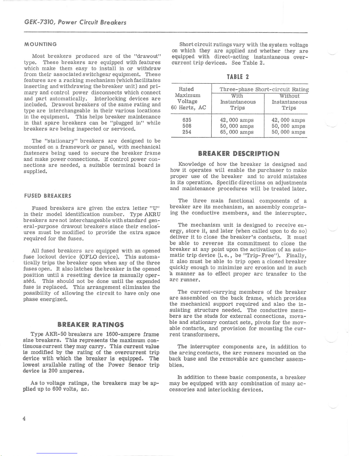
Short
circuit ratings
on which they
equipped
current trip
are
with direct-acting
devices. See Table 2.
BREAKER
IGnowledge
how it
proper
il its
operation.
and
maintenance
operates will
use
of how
of the breaker and
The three main
breaker are
ing
the conductive
The
ergy,
store
deliver
be able
breaker
matic
trip device
it
also
quickly
a
manner as
arc
runner.
The
assembled
are
the mechanical
sulating
bers
are the studs for external connections, mova-
and
ble
able contacts, and
rent
transformers.
The
the
arcingcontacts,
back base and
blies.
In addition to these basic
may
be equipped
cessories and
its mechanism,
mechanism
it,
and
it
to close the breaker's
to reverse its commitment
at any
must
enough
current-carrying
stationary
interrupter
point
be able
to
to effect
on the back
support required and
structure
the removable arc
interlocking devices.
vary
applied
IABI.T
Three-phase
42,000 amps
50,000 amps
65,000
amps
the
with
and whether they
2
system vottage
instantaneous
Short-circuit
42,000 amps
50,000
50,000 amps
DESCRIPTION
breaker
the
enable
is designed and
purchaser
the
to avoid mistakes
Specific
procedures
later
directions
will be
functional
an
assembly
members, and
unit is
designed
(when
called upon to
on
treated later.
components of a
the ilterrupter.
to receive en-
contacts.
(i.
e., be
upon
activation
the
"Trip-Free").
to trip open a closed breaker
minimize
needed.
contact
provision
components are, in
the
with
arc
proper
erosion and in such
arc
transfer
members
of the breaker
frame, which
conductive
The
pivots
sets,
for mounting the cur-
arc
runners
components,
any combination
mounted
quencher
are
over-
Rating
amps
to make
adjustments
compris-
do so)
must
It
to close
of
an
auto-
Finally,
the
to the
provides
also
the in-
mem-
for t}te mov-
addition to
on the
assem-
a
breaker
of many
ac-
Page 5
Power
Circuit
Breokers,
GEK-7310
RECEIVING,
RECEIVING
breaker is carefully
Each
before shipment. Immediately
circuit
anydamage
handling
immediately with the
nearest
notified.
during unpacking
that no damage
handling, or from exposure to
Check
that no
service
this is not
betakento insuretheproper storage of
breaker,
sustainedin
is evident,
General
is expected that due
It
parts
all
parts
have been overlooked.
is recommended that the
It
immediately in its
possible,
AND
an
examination
a
damage
transportation company
Electric
installation of the breaker so
and
occur
wi.ll
HANDLING
inspected
upon receipt of the
should be made for
transit. If
claim should
Sales
care
from
damage
Office
will
careless or rough
moisture
against the
packing
list to be sure
STORAGE
breaker
permanent
following
the
precautions
HANDLING, AND
1. The breaker should be
packed
and
rough
or
be filed
and the
should be
be exercised
dirt.
or
put
be
into
location.
must
the breaker:
against
warm dry room, since water
verse
ers for outdoor switchgear should
equi.pment only when
heaters are in
2.
cation
ticular care shouldbe
from moistwe
has
If
STORAGE
condensation,
effect on the insulation
operation
breaker
The
free
from
and
a very
CAUTION:
FOR
BE
THAT RUSTING HAS
TO ASSURE
corrosive effect
IF THE BREAKER
ANY
LENGTH
INSPECTED
DITION. SHOULD
preferably
by
absorption
parts.
be
power
should
corrosive
taken to
cement dust, as
PERIODICALLY TO SEE
GOOD
is available
prevent
to
be stored in a clean lo-
gases
or fumes. Par-
protect
this combination
many
on
IS STORED
OF TIME,IT SHOULD
NOT STARTED AND
MECHANICAL
THE BREAKER BE
STORED UNDER UNFAVORABLE AT-
carefully
MOSPHERIC
BE
CLEANED AND DRIED
BEING
CONDITIONS,
PLACED IN SERVICE.
IT
OUT BEFORE
protected
storing
has an ad-
Circuit
stored in the
and
condensation.
the equipment
parts.
CON-
SHOULD
it in
break-
the
a
BREAKER
PUTTING THE
DRAWOUI BREAKERS
mechanism used
The
force required to overcome the resisting force of
disconnects
the
onthebreaker rather than in the drawout
mechanism
This
mechanism
unit
subassembly and
assembled breaker
work on the breaker.
or
BREAKER
to
on Type AKR
IN
SERVICE
provide
breakers is mounted
mechanical
the
enclosure.
is referred to as the
the
"racking"
can be
without doing any disassembly
mechanism. It is a
added to
a completely
"drawout"
This drawout mechanism consists of a crank-
power
a
and
shaft
fastened to each end of the crankshaJt is
having
arm
in the equipment enclosure.
tates, the crank arms, acting on the stationary
cause
the breaker to move
enclosure.
screw
an open slot
crankshaft
The
which operates
which
with respect to the
engages a fixed
the crankshaJt ro-
As
it.
is driven as the
Rigidly
a
crank
pin
pin,
breaker
power
OPERATION
screw
supported by a centrally located
shaft. The
by means
crank.
will engage the square end of the
breaker. A
be moved aside
screwshaft
clockwise direction moves the breaker into
nected
breaker to move
BREAKER
drawout enclosure
even coating
bars inthe
connects
is turned in an internally
power
screw,
of an external
has,
This
sliding cover in the escutcheon must
end.
position.
|NSERI|ON
procedure
The
1. Before inserting
of D50H47
enclosure
the
of
its
on
so that the handle may engage the
Turning the crank handle in a
reverse
The
out.
(FtG.
for inserting
as
is
the breaker, apply
whichengagethe
breaker.
crank on
jackscrew,
or
handle
a square socket
end,
power
of
3)
a
follows:
grease
to the silver-plated
threaded trunnion
the crank-
is turned
in the form of
which
screw in the
the con-
this
causes the
breaker into its
light,
a
primary
dis-
a
Page 6
GEK-731O,
Power
Circuif
Breokers
5.
Extend the second rail.
6. Align the
in the rails and
ing
go
move
pins
the
all the
the lifting device.
7. Make
the trip button.
move
the sLiding
racking
clockwise
and remove
remove
the ends of the rackingshaftso that theywill engage
the
has not been
the encloswe, the
to
handle.
8.
itispossibletoturn
If
it. This step is taken to
pins
in
engage
the
pins
on the breaker
carefully
lower
to enter their slots. Make sure the
way down to the bottom of the slots; re-
sure the
breaker
While
is open by
holding in the
with the slots
the breaker, allow-
trip
pins
pushing
button,
cover aside and then engage the
handle
direction, do so
handle.
the
housing.
the
operated while the
pins
andthis stepwillnotbe
If the
arms
will be in theright
the
until
handle
If the racking
in
counter-
the stop is reached
align
breaker is
a
not
does
the arms
mechanism
position
necessary.
turn,
on
out of
9. Make sure that latches on the ends of the ex-
tended
pushing
into the enclosure.
rails are in the unlatched
on the breaker, roll it
position,
as
far
as
and
it will
by
go
10. Put the latches on the ends of the rails into
their locked
position.
in
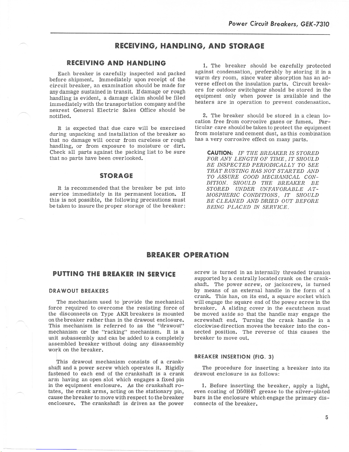
I.
Spreader
2. Drawout Rail
3. Breaker Rail
4. Slots
'
10. Movable
Fig. 3.
5. Trip Button
6.
7. Housing Racking
B. Rail
9.
(8041582)
in
Racking Shaft
Latch Link
Racking
2. Position the breaker
intended
A
3.
forward
sheets for standard
est
unlatchandpull forward
of the cubicle.
breaker
the extended
to receive it and engage
special
The
the back for AKRU fused
3.
4.
"spreader"
hooks of the
square-shaped
the door of the
Open
Raise
the
sides are
breakers,
breaker
a few inches above the slots
rail.
Pins
Rail
Arrns
Pin
Position Indicator
Inner Housing
Inserting
provided
is
spreader are
holes
one of the rails inthe sides
until the rail
the breaker
in front of
lifting device.
the
as shown
placed
in the breaker
and inthe
breakers.
breaker
encloswe,
the cubicle
in
holes near-
pins
Fig.
in the
side
and
in
the
11. Push in on the trip button, move the sliding
cover to the right,
12.
Rotate
revolutions, thebreaker
indicator
The
ment
will
control
the
the
show
circuits
is electrically
secondary
the
on about the third turn
run,
will
off switches
13.
nects,
nected;
connect the
atbd.
the breaker
testing.
charging the
are
h the test
which carry the control.
however,
power
this
At
and engage the racking
handle
left upper
the
in
when this
are
operated, the
disconnects engage.
closing spring, until the
actuated,
position,
primary
the
circuits, are
point,
may
electrical
be operated
14. Further clockwise
handle causesthebreaker to travel
position,
in the
of the racking operation,
in
of the
which also
equipment
primary
will be
compartment. During
disconnects on
handle.
clockwise. After about five
be in the test
will
side of the
position
energized
motor
the handle.
of
and
This
position.
compart-
is reached. If
breaker
the
run when
will
will occur
motor
The
cut-
the secondary discon-
voltage,
disconnects, which
are
con-
still widely separ-
control
for the
rotation of
shown on the indicator
the spring-loaded
the
devices on
purpose
the
racking
to the connected
phase
this
fingers
breaker will en-
of
6
Page 7
gage
the
stationary bar
The opening of these fingers
springswill
ment
in the racking
fali
off
travel,
About
peak
the
which
the
handle
sal
of the handle motion. Approximately
on the handle
ing cycle.
15.
The first
the enclosure,
and
the marks
grease
tracks
engagement.
attained
BREAKER
cause a noticeablyhigher
to
a lesser force requirement
at which
point
three handle
force requirement
the
ends
movement.
should be removed
are required
time the breaker
it
should
the
of
on the
marks
is
stationary
should
The maximum
g/16-inctr.
WITHDRAWAL
the
in
equipment
against the
effort. This will
a stop will be
turns
will be required
and reaching
Upon
without
for the
be completely
disconnect
bars examined.
indicate no less
amount
enclosure.
force
require-
load
quickly
very
to
the
encountered.
between
the stop
reaching
the
any rever-
24 turns
complete rack-
is introduced
withdrawn
fiagers
than
that
on the
1/4-inch
can
of the
end of
stop,
into
These
be
ers.
They should
easily
enough
the area
Iocation
ject
of the
switchboard
tions
connections
iliary
mountingholes
fastens
vertical
posed
versely
ouiline
gives
and
to
reached
surrounding
is not
chosen
to
extreme
Mounting
breaker to
tothebreaker
to the
switch
the frame
These mounting
plane.
on the breaker
a-ffect
drawing
information
a
cover
parts
live
Power
Circuit
be
situated
for
operation and
free space
troublesome.
should bedry
variations
the
breaker
its supporting
or
enclosure,
studs, andmaking
breaker
terminals,
are
If they
the
which is
or door
of the breaker.
if
required
to its
support.
holes
are not,
structure
operation
preparing
on
suitable
Breakers,
so
that
maintenance,
so
that
If it is
andclean
of temperature.
involves
terminal
these
must
furnished
bolting
structure
making
power
board and
are required.
forthe hardware
all be in
strain may
which could
of the
with the breaker
a mounting
preventing
for
GEK-731O
they can
working
possible,
andnot
the
within
connec-
control
power
the same
be im-
breaker.
structure
access
be
with
in
the
sub-
frame
the
arx-
Four
which
ad-
The
1. Trip
ton,
and move
aside to
2.
counterclockwise
the breaker
the
right.
Engage
the
sliding
the racking
direction.
3. ApproximateLy
complete the
breaker to
shown
be
because
on the
evident to the
further
the
of
racking
willbe
to discharge,
latches
out
Iifted
STATIONARY
activated.
4.
To
onthe
of the compartment.
off the
racking-out
the disconnected position.
indicator
person
stop will
a
movement
be
can
cycle,
This
but
will not
withdraw the
ends
ofthe rails,
rails
by the
BREAKERS
Stationary breakers are
mounting
in an
construction.
the drawout
drawout
and automatic
Careful
lection
on
a framework
enclosure
They
type; however,
features,
disconnects
consideration
a location
of
of the
namely,
for
hold
open,
cover in the
handle
24 turns
operation
in the
operating
encountered
be made.
the
"closing
in
and
the
of
compartment
the mechanism
beyond
Towards
spring
willcause theclosing
close the
breaker
The
lifting
intended
breaker.
completely,
pull
and
breaker
device.
or switchboard
customerts
are the same
own design
breaker unit
they do not have
the
racking mechanism
and
interlocks.
should be
mounting
given
stationary
the trip
escutcheon
crank
handle
and bring the
This
but-
in a
wiII
will be
and will
which no
the
end
interlock"
spring
open the
thebreaker
may now
for
panel,
to the se-
be
separate
or
and
as
the
break-
Another
for
the breaker
stand
and
short-circuit
be subjected.
supportedadequately
of support
enough
is
imposed
Manual
ance is
is
operated.
to the
2-l/2
frame.
Since eachupper
of two
stud must
parallel
nection.
connector
with
and lower
cable
connects
connectorb:rrs
the end
wards
yond
the
Control
made
frontarea
board
governedby
requirement
is that
the forces
Connectingbus
for buswork
to the
provided
right
arches
separate
connectors
the breaker
to a terminal
may have
breaker
on
the breaker's
breakers
for
This
from
beyond
provide
stud members,
All
members,
stationary
bars
studs.
across
of the
centerline
both halves
may
connecting
connections
of thebreaker
6, 10
the
requirements
that
currents
or busbars.
of
the supporting
it be
rigid
result
from high
to
which thebreaker
or cable
to
resist
these
or cable
so
that no
must
be located
the sweep
requirement
the centerline
the right
studof
a
solid connection
as
appreciable
studs.
of the handle
will be
of
edge
thebreaker
the
connections
well as
breakers
already fastened
These bars
will
If an
of the upper
bedispensed
base no more
the
of
fastener
on stationary breakers
board
located
(front
or 14
with.
bus
should extend in
than 5/8-inctr
hole.
in the upper
view).
points.
of the
structure
enough
forces.
must
to
momentary
must
also be
points
be
strain
so that
the breaker,
of the
11 inches
breaker
is
composed
clear-
when it
to the
across
an external
will
the two
be shipped
to both
accommodate
upper
external bar
studs,
hthis
The terminal
This
control
will
scheme.
with-
may
close
or
con-
the
case,
to-
be-
are
left
be
Page 8
GEK-731O,
Power
Circuit Breokers
If the breaker
connections
of
switch.
the
PRE-SERVICE CHECK
Before
first time, it
amination
of the breaker.
breaker
an equipment
should consist
1. Attach
onthebreaker afterpushing
ing the cover aside.
til it
Iocks
closing.
and a
on
stops.
which otherwise
has an
may be made
putting
the breaker
would be
preliminary
This
a
workbench or
drawout
the
of
following:
thedrawout
Turn the
This will
auxiliary switch,
well to
may
compartment.
racking handle
deactivate
would keep the breaker
NOTE: Remember, later,
chanism must
position
serted in the
2.
Remove the arc
examine
parts.
the
it for the
Do
preliminary
not
be set
before the
equtpment.
quencher
possibility
replace the arc
examination
directly
be carried
on
thetrip
to the terminaLs
into
service for the
make a
check
the
handle
cursory ex-
the
of
out with the
extended rails
to the shaft
button
clockwise
the various inter-
that this
back to
breaker
i,ts
original
can be in-
from each
of broken or missiqg
quenchers
is
completed.
external
operation
of
The check
slid-
and
un-
from
me-
pole
and
until after
move in
seem
this, refer
tiiled
ping
tivate
Devices
overload
voltage
("wipe")
to
do so, and
at
to the section
"CONTACT
5.
Make
breaker open Erre
the
thesewith thebreaker
in
devices,
device.
6. If the
MAINTENANCE.
swe that a-ll the devices
category are the
this
the
breaker is
the operation of the
Iifting interlock
that
breaker and that the
not be opened if the
the closing
is charged,
far as itwill
as
7.
securely.
8.
should be checked when
ers
able,
drawout equipment
spring
and
Replace
electrical operation
The
with the
wiII
drawout
the
go
inthe counterclockwise direction.
the
breaker in the
least
1/16 inch.
careful measurement
If they do not
of these instructions
"
used for trip-
operable.
closedto establish
shunt trip,
a
drawout breaker, check
Manually ac-
manual trip, the
and the under-
interlock devices. Make
(3),
pin
sliding cover
breaker is closed.
discharge automatically
racking handle is cralked
quenchers,
arc
Fig.
4,
will trip the
(1),
Fig.
Check
clamping
of electricai break-
"test"
power
position
control
compartment.
confirms
en-
this.
sure
8 can-
that
if it
them
is avail-
in the
3.
Charge
manually
as
far as it
motion
and
the closing
operated, turn the handle
(140
go
will
rdturn
it to the vertical
breaker is electrically
nance handle,
charges the
NOTE: It
align the triangular
make it
4.
Close
closed by
eon.
The
closed by
closing
chanism
tangular
This
move
the stationary
and
solenoid which is located beneath
opening
maybe
in closing
Observe
when it is
Fig. 5, to
ciosing
go
the breaker.
pushing
"quick-close"
pulling
and
may bereached throughthe large
done safelysince none
the difference between
spring.
probably
on the
the
CLOSE
forward
in thelower
in this area.
are
contacts
closed.
spring. If the breaker is
degrees), then
eounterclockwise
reverse the
position.
operated,
use
the
turn the camshaft which
nill be necessa',ry to
socket
end of
electrical
when the breaker is
The
in the handle to
the
shaft.
manual breaker is
The
button
on the
end of the escutcheon.
main
in the escutch-
breaker may
armature
parts
the
of
(See
Fig.
position
the
contacts should
If the
mainte-
be
of the
me-
the
rec-
that
64,.)
opened
A breaker may
manually
result in the same
as the
is in the rpay energy
how i.t is released.
and
'NANUAt
Manually
front-mounted
with
the mechanism
sets
spring.
either cranking
degree
The CLOSE
to close
used
button to open
If
of
equipped
breaker
relay.
or
OPERATING
THE BREAKER
be equipped to
or electrically. Both
fast-closing movement as far
contact
swing) or
may beclosed remotelyby a
action is concerned. The variation
is stored in theclosing spring,
CLOSING
operated
AI(R breakers
handles. Handle
and
A complete charge
handle
the
three cycles
the
them.
with
mounted
breaker
closing solenoid, a
a
button,
Before this can be
charges
fully
is
through
(50-degree
on
contacts and
done, however, the
operate either
types of operation
constructed
are
operation re-
the closing
accomplished in
one cycle
the escutcheon,
(135-
swing).
the TRIP
manual
control
switch
is
8
Page 9
Power Circuit
Breokers, GEK-731O
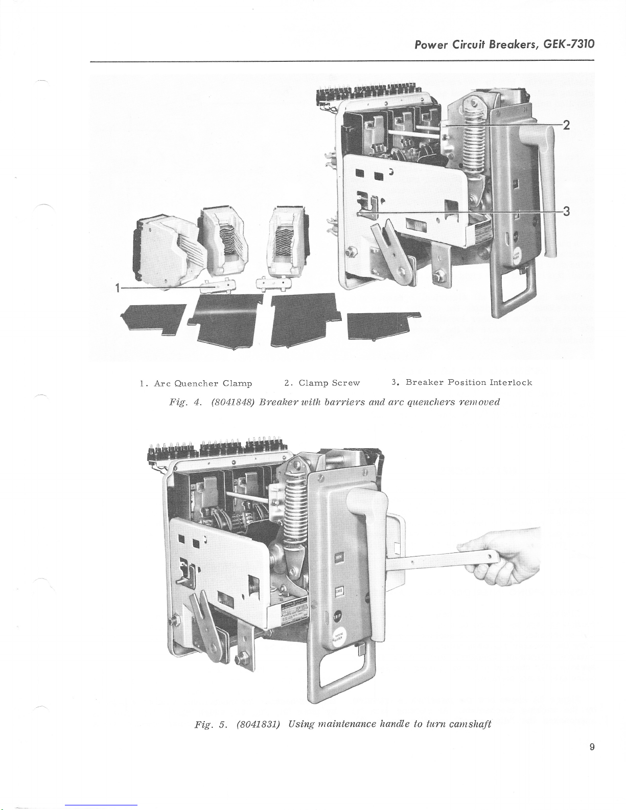
1. Arc
Quencher
Fi.g. 4.
Clarnp
(8041848)
Z. Clarnp Screw
Breaker with bqrriers
3. Breaker Position
and arc
quenchers
Interlock
remoued
Fig. 5.
(8041831)
maintenance handle
Using
to turn
camshaft
Page 10
GEK-731O, Power
Circuit Breokers
closing spring has to
closing solenoid is
supplied unless specified in the breaker
ELECIRICAL
Applying
the closing motor
the motor
of
spring is completely
spring
the closing
leases
Apush-button
CTOSING
control
circuit
is mechanically
circuit activates a
holding latch.
the
closing
electricalbreakers.
vided
only ifspecified in
plied,
it is located
When
closed
motely,
the
breaker is
either
or at
push
inthe right
in service,
by
energizing the closing
the
button
switch
so equipped).
OPENING
A closed breaker
trip latch
the secondary latch
are mounted
device.
(11),
Fig. 12, is moved
on the trip shaft,
be charged by
optiona-l
an
power
on electrical
does not
charged and
held from discharging
This
the breaker
accessory
immediately
breakers.
occur until a-fter the
overcenter. The
solenoid
switch
may
feature,
be
however, is
order. If sup-
side of the escutcheon.
all electrical breakers
breaker location
in the
THE
BREAKER
will
open
(14).
A number of trip
by
escutcheon
(trip)
off the
one for each tripping
hand. The
is not
and
order.
energizes
Cutoff
which re-
provided
circuit
operation of
(if
whenever
roller on
paddles
until
on
pro-
are
re-
ttre
the
\ri
/-
"l
a\^.
\
\N
\\l
It\
tl
12
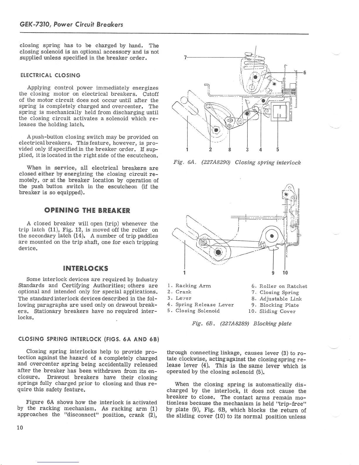
Fig.
6A.
a\
t\
\'\
\-
f..
I
.rm
(227A8290)
Closi.ng
spri.ng
interlock
INTERTOCKS
interlock
Some
Standards
optional
standard interlock devices described in the fol-
The
Iowing
ers.
locks.
cLoSrNG
Closing spring interlocks
tection
and
overcenter
after
closure.
springs
quire
Figure 6A shows
by
the racking
approaches
10
and
and
paragraphs
Stationary
SPRTNG
against
the breaker
Drawout breakers
fully charged
this
sa-fety
devices are
required by
Certifying Authorities;
intended only for
used only on drawout break-
are
breakers
INTERTOCK
the hazard
spring
has
feature.
mechalism.
the
"disconnect"
have no
of a
being
been
withdrawn
prior
to closing and
how
the interlock
help
accidentally
As
special
(F|GS.
completety
have
applications.
required inter-
6A AND 68)
provide
to
from
their
is
racking
position,
Industry
others are
pro-
charged
released
its en-
ciosing
thus re-
activated
(1)
arm
crank
(2),
I
'l
l.
Racking
2. Crank
3.
Le:'er
4.
Spring
5. Closing
through
tate
clockwise,
lease
lever
operated
When the
charged
breaker
tionless
plate (9),
by
the
sliding
Arrn
Release
Solenoid
Fig.
68.
connecting
actingagainst
(4).
by
the
closing
closing
by
the interlock,
to close.
because
the mechanism
Fig.
cover
Lever
(22748289)
linkage,
This is
The contact
68,
(10)
the same
solenoid
spring is
which
to its
6. Roller on
7.
Closing
8. Adjustable
Blocking Plate
9.
10.
Sliding
Blocking
causes
lever
the
closingspring
lever
(5).
automatically
it
does not
arms remain
is held
blocks
normal
position
10
Ratchet
Spring
Link
Cover
plate
(B)
to
which is
dis-
cause the
mo-
"trip-free"
the return
unless
rore-
of
Page 11
Power
Circuit
Breokers,
GEK-731O
breaker
the
nected"
within
inaccessible,
accident.
RACKING'NECHANISIYT
(FtG.
8)
A drawout
not be
must
contacts
automatically
the escutcheon
Unless
inghandle
link
by
in the cover
the closed
Another
that the
manual trip
the
keeping the
of the
ment of
Iong as the
Another
interlock. This
is in the
position.
mechanism
the
This
minimizes
and
breaker connected
allowed
to
are open. This
locking closed
the breaker
when
cover
this
cannot be
(2),
Fig.
ia response
positi.on.
aspect of
openingmovementof
breaker
mechanism
the contacts. This
drawout
interlock
used. Lockingisaccomplished
8
which
button
"trip-free",
will
handle is engaged.
featwe
makes thebreaker
"test"
limits
frame,
position
motion to
which
the
INIERLOCKS
to a
move unless
requirement
the
is closed.
is moved,
to the
the interlock
the drawout
moves
down
main
the slidingcover
into the tripped
so a closing
not cause
any closing
condition
is the
or the
are
possibility
power
the breaker's
sliding
"con-
those
relatively
circuit
met by
is
cover
parts
of
rack-
into a notch
being
shaft
arrangement
cams
position'
cycle
move-
prevail
will
breaker
position
"trip-free"while
moving between the
nected"
between these
an
which
the
This
keeps the breaker open even
position.
two
is coupled to the trip
"ramp"
cam
holds the mechanism latch out of
are discharged.
OPTIONAT INTERTOCKS
optional
in
in
is
as
The
interlocks.
door
mounted in the equipment
are
vices
the breaker
Iock
the
sition.
all breakers,
On
lock the breaker
to
padlock
the
in
slot
trip button
cannot be closed.
Stationary
interlock
the
shows
the breaker is open. Pin
path
of
enclosure. Padlocks
t'inner"
through
side of the escutcheon. This
the
inthe depressedposition and
breakers
illustrated in Fig.
as
plate
end
the lock bolt
"test"
When
positions,
position
the breaker is
a link on the breaker,
shaft, is displaced by
in the side of
if the closing
See Fig.
interlocks are
On
house in the
assembly
4.
drawout breakers.
possible
is
it
open by
placing
the trip button
may be
of the
(3)
(4),
is held away from the
which
the
and
the breaker
interlocks
key
and
may
"disconnected"
use
to
the shackle
hole
equipped
7.
This
main
can be extended,
"con-
at
any
housing.
position
springs
these de-
part
are
be used to
padlocks
and
out the
holds the
the breaker
with a
illustration
shaft
point
and
and
of
po-
of
key
when
aI-
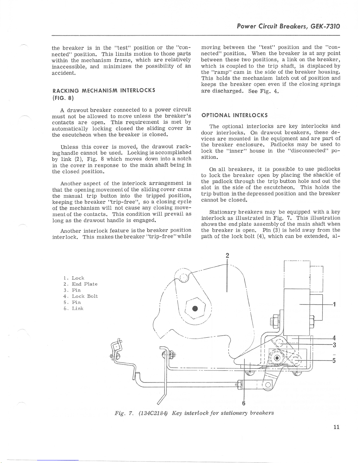
1 . Lock
End Plate
2.
3. Pin
4. Lock BoIt
5. Pin
Link
6.
Fig. 7.
i
)
\
(134C2184)
Key inteflock
stati.orwrl
for
-t-
\
\
\
\
\
I
6
breahers
11
Page 12

GEK-7310,
Power Circuit
Breokers
l.
Sliding
lowing
makes it
this
sible
sembly
causes
bolt, which cannot
breakers
used
Minor differences in
exist, but most of the devices
the key to be removed. Extending
push
moves
against
breaker latch, and
the
pin
(5).
to close the breaker.
When
is
away
(3)
pin
Accessories
from link
to move into the
then be extended.
ACCESSORTES
available
(6)
for use on the AIG-50
breaker is closed, the
the
are, in most cases, the same devices
throughout
the entire line of AK
mounting and location may
tical.
L2
Cover 2. Locking Link
Fig. 8.
(134C2179)
Drawout interlocks
the bolt
Through
the
makes it impos-
linkage,
placing,
dealt
structions; only
function it serves
SHUNT TRIP
and
metal
torsion spring
the
path
of the
plate
lock's
as-
its coil
which
in series with
made
ondary disconnects
arxiliary switch and
breakers.
bottom
themselves
breakers.
are
iden-
3. Trip
Maintenance operations, such
adjusting
and
in
with
The
is
the
shunt trip device opens
energized.
is
closed only
Button
these components wili be
maintenance
description
a
be
will
dealt with
An
when the breaker
portion
the device
of
the breaker when
frA't
the device coil.
the external tripping source
to
on
drawout
breakers, or to the
terminal board on
the breaker,
On
the
of
breaker frame in
the
shunt
trip
a
as adding, re-
of these in-
and
the
here.
auxiliary switch,
is
closed,
Connections
through sec-
stationary
is mounted
central location.
are
on the
is
Page 13

Power
Circuit
Breokers,
GEK-731O
UNDERVOLTAGE
The
undervoltage
its
coil is de-energized.
connected directly
terminaL
remains
breaker
duced to Iess
An open armature
board.
energized and the breaker
"Drop
out"
tripping, occurs when the voltage is re-
of closing.
closing, if the voltage
nominal
reason
undervoltage device may
that it wiII not cause
value.
the breaker is disconnected, and
If
the breaker is to be operated manually,
DEVICE
device
The leads
to
secondary disconnects
Under normal
percent
60
armature,
of the
than
willrenderthe
The armature
85
is
be tied or wired down
tripping.
trips the
breaker
the
of
conditions, the
may be
coil
with resultant
of the rated voltage.
breaker incapable
"picks
percent
up" ald
or more
for some
MAIN
SHAFT
(BREAKER
CLOSED)
when
are
or to
coil
closed.
allows
of its
the
so
STAT]C
In
addition to
tripping
a
time-delay
mounted
Fig.
21.
other than
former
breaker)
rating
connected across
of 100
When
static delay
connected across
static
box through
breaker.
will be shown
more
No
should be used
delay unit.
The static
furnishedwitha
on
wiring diagram,
windings
motor
undervoltage
motor load.
TIIYIE-DEIAY
device
undervoltage
time-delay
If the.aic
208/240V
(also
remotely
must
be
volt-amperes.
installed,
box.
The secondary
on the
than
UN
DERVOTTAGE
the
instantaneous
mounted
on the
unit.
control
ac,
mounted
used. This
the voltage
terminal.s
coil
The
terminaLs
the secondary
breaker
undervoltage
one
includes
Its
voltage
a control
must have
No. 1 and
of the tripping
No.
disconnects
wiring diagram.
in conjunction
time-delay undervoltage
thermotector
Fig.
causes the thermotector,
windings,
to
device
open. This
on the breaker
controlunit, as
22.
undervoltage
breaker,
the
a separately
diagram
with respect
to be monitored
4 and
disconnects
is
shown in
is
anyvoltage
power
minimum
a
No.
No.
to be
tripping
with one static
can
Overheating of
imbedded in
de-energizes
and drops
static
trans-
to
2
of the
unit is
5
of the
of the
used
device
time-
also
shown
motor
the
is
be
the
the
the
Fig.
(0134C2181)
9.
lockout deuice
HOLD.IN
Holding
link on
electric
ETECTRIC
The
voltage device
its mechanism
voltage
thus
Once the
trip the
mechanical
of the device.
LOCKOUT
electric lockout
to
i-f the
device
cannot be
breaker
coil
closed unless
breaker
link is used
See Fig.
vides a means
breakers
time. Each
series
other breaker
On
arrangement
closing
vided to
ure 10
located
cutcheon. The
access to it.
so that they
undervoltage
with
a
'8"
for
breaker
each
is made
the
with
aLlorr
shows this
in the
'?start-up"
opening in
breaker doormust
DEVICE
device
keep the
breaker
not
is
is closed, Ioss
because,
utilizes
breaker
from resetting
is open
energized. The
voltage
voltage
of
in the
closed
to hold down
9. This
of
electrically interlocking
cannot
arrangement
be closed
coil may
auxiliary
cross-interlock
having
switch contact
purposes.
an electric lockout,
which will
coil de-energi-zetl.
device.
on
"dead"
The
the lower
systems. Fig-
push
part
be opened to
under-
an
the
and
is on the
under-
breaker
coil.
not
wiII
position,
the
armature
pro-
two
the
at
be
same
wired in
on the
an
allow breaker
is
shown is
the
of
pro-
es-
gain
13
This
slide
a
Page 14

GEK-731O,
Power
Circuit
Breqkers
+-i!Lr-
i+.++-l
T l-*r 1
tr ll
'-L-
-rL'
Fig. lQ.
AUXITIARY
AII
breakers
SWITCH
electrically
having shunt trips
operated
iliary switches. Depending
of the
tain from two to
has
tacts
or
Drawout
wired
may be wired
breaker's
ttAtt
one
are
openedor
closed.
breakers
to secondary
application,
six stages. UsuaIIy,
contact
"B"
directly
and one
closed
contacts are
have their auxiliary
disconnects;
to the switch
/-lr
i.i;) Y
\-:/
Q134C2182)
electric lockout
manual
breakers
are supplied
upon the requirements
the
ttBtt
contact.
as the breaker
the reverse
stationary
and
switch
terminals.
with
may con-
each stage
ttAtt
is opened
of this.
contacts
breakers
',
'"/,/
\\
\.
deui.ce
\
\
".
//
Arm.ature holdi.ng
action
It will
action of the
aux-
con-
tective relay
sult in the remote
The
pushing
shunt trip. In the
contact of
parallel
the shunt-trip circuit.
turn off the alarm.
also
\@w
mechanismfor
automatic
of one
not be activated by
bell
in
with
its
of
shunt trip.
energizing the
alarm
alarm
manual trip or by
the
A
action.
circuit may be turned
latter case, a normally open
the bell alarm switch
"A"
auxiliary
Closing
the
PUSH
TO
IN
DEFEAT
LOCKOUT
protective
manual tripping or
remotely
shunt trip will
devices.
mounted
not re-
off by
energizing the
must be wired in
switch
the
contact
brea-ker will
the
pro-
in
BELI AIARM
give
device is used to
This
the breaker's
of
having
a
tripped
remote
open
t4
indication
through the
bell alarm device may be equipped
The
Iockout iink
the bell
supplied
alarm device is reset.
The bell alarm
only when
which
will
lock
breaker open
the
is not a standard
specified on the
with a
until
device and is
breaker order.
Page 15

Power
Circuil
Breokers,
GEK-731O
SAFETY
WARNING:
BEGINNING
ON THE
CONNECTED
SOURCES,BOTH
AND
IIOPENII
WORK IS DONE
CLOSING
ALLY
SHAFT
SPE/NG DISCONNECTED,
MAY
MAINTENANCE
FIG.
BREAI<ER,
THE BREAKER
SPftING
DISCONNECTED
OF
BE
CLOSED
5.
PRECAUTIONS
BEFORE
ANY
FROM ALL
POWER
POSITION.
ON THE
THE MECHANISM.
HANDLE
GENERAL
Breakers
plementation
periodic
A
frequently
breaker
Itwould
year.
a
an area
phere,
should
should
of a
inspection
be
systematic
routine
an inspection
will
dependonthe
be
well
to inspectany
If it
is frequently
of high humidity
the frequency
be increased.
tions, inspections might
BREAKER
INSPECTING
MAINTENANCE
IT
MUST
AND
CONTROL,
MUST BE
ALSO,
BREAKER,
IS TO
of
Under
BE MECHANIC-
FROM THE
WITH
THE BREAKER
SLOWLY,
cared for
maintenance program.
is
is made
circumstances
operated,
or
a
maintenance
be monthly.
USING
AS
SHOWN
through
recommended.
of an
breaker
or installed
dusty,
extremely bad
oR
WORK
BE DIS-
VOLTAGE
IN THE
BEFORE
THE
CAM-
THE
THE
IN
the im-
individual
of its
at
least
once
dirty atmos-
inspections
condi-
TIAINTENANCE
service of each breaker in turn
maintenance,
a high
reasonable stock
be
a
level
good
means
will be done
Maintenance
of cleaning
breaker components.
tions will comprise
erations
after new
useful
inally
How
use.
in
spring from the mechanism's
inch
and
parts
for
adding accessories to breakers not
equipped
NOTE:
ment
must haae
cranked to the
operate nonnally.
Seruice
ARRANGING
Figure LL shows how
wrench is used
an
is
excellent means
of service
reliability. Maintaining a
of recommended
for inspection and
of ensuring that maintenance
quickly.
work
and replacement
descriptions
any adjustments
are
installed.
with them.
Breakers
in most
will,
of worn
Mostof
oaithdrawn
thefollowing instruc-
that
of replacement
They will be equally
from
their drawout
"connectedt
See Step
Check" instructions.
THE BREAKER
srow crosrNG
to disconnect
camshaft.
to remove
the
of establishing
parts
spare
cases, consist
damaged
or
may
be required
equip-
mechanism
position
7
of
ttPre-
to
FOR
the closing
A l/2-
hex-head
bolt in
will
work
op-
orig-
Amaintenance
all
visual
ing and
trically
cycle should be
be
made
arc
Contact wipe
maintenance
If
found
moved
latingsurfaces
that could
If
contacts
It
cluded
breakers
ing
maintenance
program,
check
opening operations.
operated, at least
contacts
of
quencher
grease,
dirt,
on any
by
a thorough
cause a
breaker has
a
should be inspected.
good policy,
is
in an installation,
to install
providing
inspection
and the
observed. A
and
plates
side
should
section
parts
be checked as
dealing
or
any other foreign material
of the breaker,
and careful
shouldbe
loss
interrupted a
if
a
in the
work.
for
should include an
observation of a few
the breaker
If
one electrical
close inspection
the
inner
surfaces
and inner components.
described
with contacts.
it should be re-
cleaning.
checked
insulating
of
number
to
place
In
periodic
a
for any conditions
properties.
short circuit,
of breakers
have
one
or
breakers
of
cases, a
such
withdrawaL
more
over-
clos-
is elec-
operating
should
the
of
inthe
is
Insu-
its
are in-
spare
requir-
rotating
from
Fig.
11.
(8041
8
33) Dis
cormecting
closing
pring
s
15
Page 16

GEK-731O,
Power
Circuit
Breokers
the bottom
operation
has
been
of
extension.
ratcheting
the
camshaft,
breaker
the
(See
ton must
should
roller
Fig. 6.A.
be
solenoid
When this
continued.
Closing
action
way of
contact
procedures
the
erate
sliding
inspection
of the mechanism
judging
relationships.
breaker
general,
In
lubrication.
surfaces
D50H15.
should
be
of the
must
discharged
springassembly.
bedone
After the
maiatenance
closing
be
operated
on
the ratchet
this
At
)
pushed,
must
is
the
pulled,
be
done,
breaker
the
described
in
this
manner.
TUBRICATION
the
circuit
should
periods
Sliding
lubricated
with
silver-plated
onlywhen
and
is at
its
bolt has
handle
the
stops against
point,
been
may
breaker
only
the manual
or the armature
move
the
to
slow
closing
slowly,
while
and contacts,
correctress
Some of
later
of mechanical
will involve
breaker
Mechanical
be lubricated
a
with
bearing
thin film
GE lubricant
part
This
the
closing
shortest
removed,
be used
of the
spring
condition
to turn
slowly.
to
point
the
prop
the
Ctose
of the
prop
the
action
observing
where
closing
away.
may
is a
the maintenance
operating
requires
at
of
GE
contact
points
the
regular:
lubricant
surfaces
Db0H4?.
mod-
the
The
link.
Uut-
be
the
good
and
and
Hardened
latch
underthe
surface
On drawout
disconnect
Specification
grease
and
bearing
CAUT|ON:
SHOULD
ACCUMULATION
NOTE:
bearing
the
cotton
and
surfaces
ALL
BE
REMOVED
The
use
surfaces
raaelings
bearing
of the
bearing.
breakers,
studs
should
D50H47.
REPTACEfiIENT
OF COfiTPONENTS
tvtEcHANtstvl (FlGs.
The
mechanism
cam
rotates.
13;
clockwise
in
12,13,
closes
(Counterclockwise
Fig. 14.
dirt
should
by using
.EXC,ESS
OF DIRT
of
cotton
should
may
become
surfaces
the
contact
greased
be
AND
ADJUSTMENT
AND
AND
the
)
be
removed
kerosene.
LaBRICANT
TO AVOID
ANY
OR DAST.
waste
be
and
ACCESSORIES
breaker
to
auoided,
entangled
destroy
surface
with
GE
l4)
in
Figs.
wipe
as
the
Grease
when
12 and
from
of
the
the
16
4
5
Fi.g. 12.
6
(108D8131)
7
Electrical
I
breaker
mechalnism
t2
lt
t0
l.
Closing
2.
Prop
3.
Carn
4.
Carnshaft
5.
Carn
6. Holding
7.
Ratchet
B.
Driving
Gearrnotor
9.
l0.
Trip
1
1.
Trip
12.
Insulated
13.
Main
14.
Secondary
15.
Opening
Spring
Roller
Pawl
Wheel
Pawl
Shaft
Latch
Coupling
Shaft
Latch
Spring
Page 17

Power Circuit
Breokers,
I.
2. Prop
3. Carn
4.
5, Carn
6. Holding Pawl
7.
B. Driving Pawl
l0 .
.
11
12. Insulated
l0
I3. Main
ll
14.
t3
I5. Opening
16. Manual
GEK-73\O
Closing Spring
Carnshaft
Roller
Ratchet Wheel
Trip
Shaft
Trip Latch
Coupling
Shaft
Secondary
Latch
Adjustrnent
Link
Spring
13.
Fig.
TRIPPED
(108D8130)
Manual
2.
3. Carn
4. Carnshaft
5.
mechanism
Prop
Carn
Roller
RESET
10.
Trip
Shaft
1 1.
Trip Latch
I 2. Insulated
I3. Main
14.
Shaft
Secondary
Coupling
Latch
CLOSED
Fig.
(108D8132)
14.
Mechanisnt
t7
Page 18

GEK-731O, Power
Circuit Breokers
Fixed centers are shown
prop
The
holds
has
the cam roller in
been raised by the
holds the
to move
On
shaft of
ing the driving
ratchet wheel.
Fast
goes
over center, unless it
(not
shown)
wheel.
position
in
a
When the
terclockwise, a
is free to
prop
in
the
out of the wav
electrical
gearmotor
the
cam
acting against
Figures 12
breakers,
pawl
action occurs
just
manual
and
over
strong torsion
shaded in Fig. 14.
rotate
cam.
position
of
turns the
to
reciprocate,
13
center.
breaker handle'is raised coun-
on the cam shaft. It
place
after the cam
light tension
A
shown,
the cam
roller.
the eccentric
camshaft by caus-
advancing
the
when
closing
is held by
a stop on
the
show
closing
roller
spring
but d.llows it
output
the
spring
prop
a
the
link
ratchet
spring
spring rotates the
driving
the camshaft.
position pulls
rotating the camshaft.
'YlECHAN
(FrGs.
If components
new
ponent
venient to
pawl
ISIVI REPTACEMENT
rs
Figure
complete
general
If
a
replacement
assembly
Returning
the chain on
AND
16t
16 shows
until
t engages a notch
th
handle to
the
sprocket segment,
the mechanism
of this unit require
sub-assembly must be installed.
overhaul involving
extensive com-
is undertaken, it may
separate the major
breaker sub-assem-
blies as shown in Fig. 15. If this
secondary disconnect
assemblies
should be removed
first.
ratchet wheel
The
vidual component
fastens it to the
may be
by driving out the
camshaft.
replaced
sprirg
on
its normal
sub-assembly.
replacement, a
be con-
is done, the
as an indi-
pin
which
(108D8127)
15.
Fig.
18
Assembly
of
frames,
quenchers,
arc
and secondany
disconnects
Page 19

Power
Circui| Breokers,
GEK-731O
Fig. 16.
LATCH
The
is set byan adjustment
mechaaism
three
and
causes a
made,
screwed,
'VTANUAt
The
adjustable
of the
this iinkis
in the
center
dle of
enA ?/16-inch
The
having the link too long,
extend the closing
or it can be
on the up-stroke
(8041918)
ADJUST'VIENT
position
reset
Mechani.sm
of the trip latch
screw on the left side
frame. The adjustment
one-half turns
closed breaker
the screw must
three
and
one-half turns.
HANDTE ADJUST'NENT
manual handle
controlled byturninga double-ended
the link.
of
the stud
handle
allows
wrench.
can be
too short
adjustment is made
(16),
link
the engagement of
out of
spring
and
the handle.
of
subassembly
(11),
Fig. 14
of the
is correct if
the adjustment
of
to trip. If this check
then be
Fig.
A hex section in the mid-
adjustment
set
13.
back,
The
in which case it wiII not
enough to
not engage the camshaft
go
over center;
screw
or un-
by means
length
stud
an open-
either by
it.
the best
stroke of the
in the
rarge
The
confined
of the
setting in
wrench
space available.
the
CONTACT ftIAINTENANCE
CoNTACT REPTACETVIENT
Brea-kers whose
terruption
of
the replacement
rule
for determining the need
Ioss of
one-half or more
tip material.
contact surface does not indicate
to carry or interrupt
application
high
currents may
of their contacts.
Roughening or Iight
The contact arrangement
arcing contacts, two
main
contacts.
movable
Two
contacts in closilg.
These
contact
Arcing contacts
removing
pivot
insulating
pin (?)and
arc
is
moved
pieces
purpose
diameter
while
end
of
ing it in
tact stop) and
the
be
(10)
removing
low.
(6).
runner
htermediate
by disconnecting
on the springs
holdhg
of the contact. A
outer
A
spring
ordered
Contact arms are
connecting
arc
the
When reassembling,
spacers on the
the insulatingwashers
fastening
engaging a
of
mnner
(2)
and
of 1/16-inch.
the contact, it may
position (with
extending
end
of the contact.
puller
under
the
is available for this use
Cat. No.
them to the insulated
fasteners and
adjustment
middle
imparts
of the mass
current.
intermediate contacts, and
are
arms
(1),
Fig. 17,
(5)
ends of
screws are
main
(9)
have a
spriag
When the spring is
contact is replaced by hold-
its inner end behind
and
removed
is
of
15-degrees movement
(FlG.
requires frequent
of replacement is
provides
the stationary contacts.
act against
degrees
300
the
range. Each
17)
eventually require
pitting
any loss
general
The
the contact
of
of
of the
ability
sets of two
the stationary
are released by
and
contacts
their
puller
engaging the spring
016585712G1.
pins
arcing
the
make sure
the
arcing contact
(8)under
replaced.
springs.
small
having
be lifted
the lower
(3)
The end
hole
the con-
and
contact
that the
are
for
a wire
pulled
off the
by drifting out
link
and
pivot
the
from
with
in-
the
six
re-
the
on
may
pin
then
be-
the handle stroke
If
sp::ing, the maintenance handle
plete
spring charging.
closed and opened and
the wrench engaged, and looking
With
the breaker,
lengthen
the
turning
link.
The opposite motion
does not fully extend the
The
the handle adjustment made.
the wrench clockwise
can be
used
to com-
breaker can then
down
will shorten
be
on
will
When replacing the arms, make sure that all
spacers, springs,
their original
Right
move and
pin
the
of
insulated
position.
angle
tru-arc
replace
which
coupling.
and
washers
pliers
the tru-arc
connects the contact arms
are
returned to
are
needed to re-
retainer on the
end
to the
19
Page 20

GEK-731O,
Power
Circuil
Breokers
.
I
Arcing Contact
2. Interrnediate
Main Contacts
3.
bolts in the
two
The
screwed in until
CONTACT
When
justed
between
velops when
that does
"Wipe"
contacts
sured
on a stationary
the
and
is closed.
since
a sliding or
motion.
ADJUST'IAENT
contacts
sure that the
to be
the movable
the breaker is closed.
this is called
distance through
is the
move
as
position
the
distance between
the
Actually,
contacts
"scrubbing"
4.
Contact
6.
contact
they bottom.
are
replaced,
proper
and stationary
the
breaker closes.
the
when
contact when the
the same
of
point
the wiping
over-travel.
action
Contact
Arrn
Arc Runner
Fig.
pivot
Contact Pivot
(1s4C2174)
17.
are
Arcing
afm
they must be
amount
The
"wipe"
which
point
the
breaker
when
motion
"Wiping"
to the contacts
of
contacts
adjustment
adjustment.
stationary
the
is mea-
It
of
is
breaker
the
is
imparts
to be
ad-
force
de-
contact
open,
greater
7. Arcing Contact Pin
Insulating W'asher
8.
Contact
9.
Contact
the intermediate
to the
where
arc runner, and
it is dissipated
The
ment
on
1.
Thebreakermustbe
ers
removed.
2. Place
material;
and intermediate
two-inches
about
the breaker
when
mediate contacts do
3.
Close
place.
in
"over-hangs"
I0.
11.
Spring
assembly
contacts, to the
rz.
finally
and
extinguished.
steps to follow in
AI(R-50 breakers follow:
making the wipe
open
a thin
suchas
sheet
mylar,
strip of tough
or
over
contacts. This
and must be
rvide
is closed, the
not make contact.
the breaker with the
Examine the
below the
insulation to
intermediate contacts.
Coupling Pin
Insulating Coupling
Adjustrnent
Stud
arcing contapts,
quencher
to the
the
arc
adjust-
andthe
arcquench-
insulating
stationary arcing
strip should
placed
arcing
insulation
make sure
and
so
inter-
held in
be
that
it
The wipe
makes correct
results from interrupting
the
of
20
arc
adjustment on AKR-50
the
transfer
action of
fault current.
is its forced sequential
movement from
breakers
the arc which
also
"Transfer"
4. Attach a continuity
the upper and
not an
cise
ohmmeter.
an
lower stud. Use
indication.
Iatter does
The
checking
means between
abell-set or a light,
give
not
as
pre-
Page 21

Power Circuii Breokers,
GEK 73lO
5.
Facing
clockwise uatil it is indicated that the main
stud
contacts have parted. A ?/16-inch end wrench fits
the hex
6.
Slowly
main contacts
the
7.
Turn
point
2?0 degrees.
distance from flat to
the hex section
8.
Trip the
and
remove the
It is rec ommended
in the
the breaker, turn the wipe
section on
the
stud.
the stud counterclockwise
turn
touch.
iust
the stud counterclockwise from this
will be 4-l/2 times
This
flat or
of the
stud.
breaker
insulating strips.
that this
course of routine maintenance
from
to
avoid
adjustment be
accidental
adjustment
point
to
inspections.
until
the
point
on
tripping
c he cked
COMPONENTS AND ACCESSORIES
AUXTHARY SWTTCH
auxiliary
The
right
side of the
main
the
justable
shaft
Iink
which
(FrG.
18)
switch is mounted
mechanism
operates the switch through an
connects it to
frame.
the
the upper
on
A crank
switch crank.
on
ad-
I
;l
ll
ir
)
Replocement
switch may
The
two bolts
The replacement
shaft
shaft
is
open.
If
which
so
set
points
a
switch is added
the adjusting
fasten it
the arrow head
that
as
shown in
tink
This is connected
tened by means
lustration.
Adiustment
of
If the adjustable
should
between
be
pin
After
should be checked.
the contacts toward
normallythe
before installing,
set,
centers.
installing
contacts.
'rBrr
be dismounted by removing the
to the
switch should
mechanism
have
its
on the end
frame.
crank
the
of
Fig. 18 when the breaker
to a breaker
having
none,
will also have to be installed.
a
cotter
link
mainshaft
pin
shown in
as
is installed, its length
to the
at
a new
Viewing
switch, its operation
the switch from above,
the front of the breaker are
Even if a special switch
and
crank
the il-
6 3/8 inches,
fas-
I . Main
2.
3. Adjustable
Fig.
is used, it is always
stages nearest the
the
"A"
"8"
"slow-close"
use
Shaft
Crank
Shaft
(22748296)
18.
aiew
Link
from
Auxili,a4,
left
-
the case that
crank
front, and the
contacts
contacts
To check
of
are closedwhenthe breaker is closed;
are
closed when the
the setting, arrange
as
described
a continuity tester, observe
contacts towards
"A"
the breaker contacts when
this
point,
the breaker
range of having a
in l/4-inch.
is made by disconnecting
adjustable
link
touch.
should be within the
to
end of
required.
At
being
wiped
Adjustment
the
switch
breaker
have
the
page
on
the switch
and
varying
t+.
(
Contacts
Contact s
and linkage
open
the first
contacts to
"B"
the back.
breaker is
brealer for
the
15.
Through
the
"A"
open.
position
contacts
arcing contacts
1/4-inch
the upper
its length
two
the
of
gap
as
2l
Page 22

GEK-73\O, Power Circuit Breokers
SHUNT TRIP AND t'NDERVOTIAGE DEVICE
(FrG5.
mounted
A
devices,
voltage
Re
devices,
mounting
19 AND 20)
As shown in the illustrations,
tothe underside
breaker may have as many as
plus
device.
plocemenf
secondshunt
a
If it is necessary
the easiest
braeket
(3),
of thebreakerfront frame.
tripor
to replace
procedure
Fig" 19,
or
these devices are
each
one
a
secondunder-
add
one of these
is
to remove
from the breaker
of these
the
frame
If
ing bracket
(4)
and
a
replacementor
will be supplied
If a second shunt
(6)
vice
additional
bracket
used
frame.
is added,
bracket
is fastened by two
to fasten
If the second
device, a new
plied.
t}tebuffer
andremounted
This is
assembly
remove
the buffer
buffer
required for clearance.
together with the number
the device
newdevice
(5)
trip
this is mounted
(?)
as shown.
assemblv to the breaker
device added is an undervoltage
assembly block will be
mustbe
taken
from the bracket.
is
ordered,
with the device.
or undervoltage
by means
This
of the hex head
In this case,
disassembled,
off,
two under-
a mount-
additionaL
of an
bolts
sup-
de-
(8)
li'-/
4r+ |
l3
9
i
I
I
I
3. Mounting
4.
Breaker Frarne
5. Second
Shunt Trip
7. Additional
8. Fasteners
As
sernbly
Buffer
9.
.
I0
Arrnature
.
1I
Magnet
12.
13.
Paddle
Trip
Second Trip Paddle
Bracket
Bracket
for Bracket
to
tl
5
19.
Fig.
22
(0108D8125)
Shunt
trip
mounting
Page 23

-'1
,Lt'7
ill
rill
Power
I
g
Circui| Breokers,
GEK-731O
voltage
buffer,
faces
sion carefully
breake r
Adiustment
device.
carefully
the threaded members
of
w ir ing diagram f
20.
Fig.
Before disassembling
measure
the
on
the distance
new
assembly.
the
or
and set
coil lead connections.
(0108D8126)
the
original
between the
this dimen-
Refer to the
K
Underuoltage deuice
If the
check the mounting fastenersto nake
reasonably tight. If they
paddle
tance between the trip
trip
bending isnecessary,
done.
on
paddle,
mounting
trip is not
shunt
the trip
and recheck for
2. Undervoltage
4" Breaker
5. Second
8- Fasteners for
q
tz-
I3-
6
rb.
to
shaft
arm of the, device and the
be
Frarne
Undervoltage
Accaal'lrr
Buffer
Trip Paddle
Secorrd Trip Paddle
Adjnstrnent
Electrical Interlock
Lever
Locko,ut),
Check
Garrge
successfuI
(Undervoltage
Point
Bracket
Screw
for
Wire
in this test,
they
sure
are, then bend the trip
slightly
careful thatit is not
reduce the dis-
positive
trip. If this
over-
are
these devices are
When
positive
their
demonstrated.
placing
magnet of
armafure
a
ability to trip
This is done
l/S?-inch
the device
trip the breaker.
to
shim
between the
and
installed
the
breaker
the
on
manually operating
replaced,
or
must be
trip by
shunt
armature
and
the
Undervoltage devices; trry fte
urrmature opens. This
armature to
extension
the front
frame
strike
on the other end
of the
breaker) extends:
and limits
causes;
paddle
the
tfie mov.eulentt
breaker when the
an
extension on the
on the trip
of'the arm,ature
ttrough the device
of'the
shaft.
armafure.
An
(towards
23
Page 24

GEK-731O,
Whenthe
against
check
To
down.
inserted
be
released.
ture
iscorrect,
(16),
Fig.
inside
to be
If the
tripping
paddle
furns
half
When
breal<er
betweenthe
ance
'NAINIENANCE
UNDERVOTTAGE
FOR
the event
In
lowing
whether
static
Power
armature
top
the
positive trip,
the end
against
The
20.
the slot.
undervoltage
ability,
assembly
until the check
undervoltage
the
mechanism
checks
the magnetic
time delay
Circuit
is released,
the
of
slotthrough
the
at/}2-inch
of
the
top of
If thistrips
place
toinsert
that only
Note
device
adjustment
the
may be
is reset,
trippaddle
STATIC
OF
the device
pecommended
ztre
device on
is the faulty
unit
Breokers
armature
diameter
the slot,
the breaker,
the tip of
does
turned
is
zuccesSul.
device
there
andthe
DETAY
(FlGs.
2l AND
fails
extensionstops
this
which
protrudes.
it
should
wire should
the
and
the
is
thewire
not
screw
in
is
closed
device
pick-up, the fol-
to
the breaker
component.
shown
the
have
of
increments
be clear-
must
armature..
DEVICE
22)
determine
to
held
be
arma-
setting
at
is
wire
positive
the
trip
of
t\e
and
the
or
1.
Check
on static
the
box.
Device
a.
Device
b.
Device
c.
2.
Check
undervoltage
mate voltages
208-volt,
a.
230-volt,
125-volt. d-c
b.
250-volt, d-c
c.
3. The resistance
follows:
6275081
a.
b. 62?5081
inputvoltages
These voltages
1??L316
17?L316 G-14
1?7L316 G-15
output voltages
c-12
device connected.
as follows:
are
177L316 G-12
a-c
17?L316 G'12
a-c
17?L316 G-14
177L316G-15
the
of
c-59
G-61
1830 ohms
=
440 ohms
=
acrossterminals
should
=
terminals
on
undervoltage coils
be as follows:
230
208
or
125 volts,
=
250
volts,
=
110
=
=
=
100
=
volts,
4
and
The
approxi-
volts'
120volts,
50volts,
volts'
I
d-c
d-c
and
5
with
are
2
a-c
d-c
d-c
d-c
d-c
as
M€
CUsTo
Iq
230v.60N5Ec,
MINIMUM
R'5
A NS
F0RM€€
SIZE
too
vA
-
A
25oV.
Cr,Cc,Cs,Ca,C'r
-
C2
5 5oaF 350
j
- l00o Af
C
D,,D4,D5 D5,D1
R,-t5aZW!5%
I
Fig.
D.c.
2oo
l+
C4
TP'
AY
L
Re
-
-lop{
wvDc
wv
DC
-
lN5!o
(102C3698)
21.
!to1o
-60o
600WVDc
4\@30'c
Static time-delay
TE3
Rz-
Rr
R+,
RA
RH-
R9'
Ju,{p*
?o'V
-
Rs,
-
LTSo
roe
APPL.
rL
l5oo
5W
5w
75 'rt
lo
R-l -
Rc,
tL
Zo\^t
o-25,ooosL
5oo -n- 3W
underaoltage
TB6
Rt
CON'iACT9
TRIPI'IilG
co!NEc'ED
Nor
15
U,V,
R
oR
R€QI]'
To
't
TB
5
PusH--boTToN
RELAY
FOR
'N5T.
To
Ei:
c""tott*'
BY
lNsT
U.V
L___--
!5"h
't
s7o
I
Yzw
t
5
%
W
25
r
52o
wi.ring
Mp€
Ju
diagrom
24
Page 25

250UDc.
A-
ct,C4tc5,
C2-55oa{
Ca-looo4f, 2oowvDa
Q'Da,D5'Da,Dl-
&-
R2-
R3-754
Rq,R5,Rc,R7'
Ra-
Rl-
Rg'sooe 3w
Rn,&t-
F-
7'THE,qHorEcroR
X-
7-
ct,C1
600 wvDc
356wvDC
600
ma.
/5^
2u/ ! 576
/5oo^
5u./
5W
/oathV.
Zz'ott
o-?sK 25W
5o^
/AnP
Dlii
TPAN'E
/?uA.c.
RELA/
REL^y
-
/o4/
lN560
@
3o"c.
t
5Z
!57.
?oW
t57o
?5w.
Fa5€ TrpE
//s/?io\/Ptu
Power
I
/o%
Usep
Junpet
WHEN
CoNf
SrAr/c
FoR/ilsr
SHouLo N/RE
sR/ES MrP
!
57"
/u
Ouu
TflERHo.T€cT&
U'ED N/D1
/J
72
auJloqeR
fR/l
lv
PA.
C.
TtrRma.rtcransi
-
3ui"
oo
rr
/
Tlltpua-rscra<
CourRoL
'ery/K'Lill
Circvii Breokers,
rrl-t/;!;"i%"
J_I-',y^:,^, ?8v
__l
l-{-a- |
---__l
A
|
tl
|
I
I r I
,-ecroe
,-Ec-oR
foR,aER
AuAltA8/z/ar:
SHoutD
lit-oirer,ua
tND,CAT€5
Pas.
Pa5.
5€c.
NOr
STARTED
t/6Hr
|
|
GEK-731O
tresr
/Da<hd-
& Teaus
& 7RAils
volTAGE
tTdroR
BE
LlNr/t
/ND/cArEe
,@
-24y'
5t<.
Nor€-
MR/il6
7//ERnorEcrdR&
'.iHE{
I
I I
i i
/e;'Ttn;.--l-+,1
I lR+
I
r'
r
I
I
I
I
t__
I
i+ fo' .*
_=:7,'*
i-
_
--
___l
-__.lt
_i
CuslahEp's
fRrysFoRb€R
23ov.6oN
t//N/.|uM
StzE
loova.
sEc.l
(.,/
<t:l
<[t
iiii
WARNING:
CHECK
CUIT
CONTINUITY OF BRIDGE
IN
STATIC TIME
ONLY A
VACUUM TUBE
BE ASED.
ETECIRICAT
Figure
components on
open and
The application
run
because the
chanical F
only after the
slightly
mechanical
a
The close
which closes its
solenoid.
allowing
The W
on
automatic
moved
CONIROT COI'IPONENTS
23 shows the connections
electrical.breakers with
the relays de-energized.
G
and
closing
over center. The closing
latch.
signal completes the X
This
the
breaker to
prevents
relay
opening
and then
reapplied.
Fig. 22.
(102C3699)
Wirirg
underooltage deuice used
DO NOT USE
BELL
SET TO
CIR-
DEI.AY BOX;
VOLT-OHM
VOLT
METER
METER
SHOALD
for control
the breaker
of voltage causes the motor to
contacts are
G
switches Erre
spring
contacts,
removes
close.
a
urdess
closed. The me-
arranged to
is
fully
charged and
spring
is held
relay
energizing the
the mechanical
second close
the
close
operation
signal
di,agramfor stati,c time-delay
Thermotector
with
OR
operate
by
circuit,
closing
latch.
is
re-
CC
D
E
F&G
L
@
w
x
X
J-
't-
+
Fig.23.
-
- CLOSING
- ANTI-PUMP
- MECIIANICALLY
-
.
-
-
- NORMALLY OPENSWITCH
-
(1
cqntrol
CLOSING SOLENOID
AU)CTLIARY
CLOS ING MOTOR
ANTI-PUMP
CONTROL
CONTROL
NORMALLY CLOSED
56A2395)
RELAY CONTACTS
REI.AY CONTACTS
OPERATED
SWITCH CONTACTS
RELAY COIL
RELAY CONTACTS
REI.AY COIL
Electricall5,
diagrant
SWITCHES
CONTACTS
SWITCH CONTACTS
operated wiring
25
Page 26

GEK-731O,
Power Circuit
Breokers
Replocement
gain
To
ponents,
access
the breaker's
beremoved. Before thisis done,
placed
should
keep it
escutcheon removed. Mounting
the X relay
This mounting
mechanism
screws.
to
side
from
for all
be
from tipping
Figure
24
shows
(2)
and
bracket
side
Removing these
pulled
be
plates.
the left
forward from between the mechanism
The W
side
thedevicesandthe wiringharnessto
frombetweenthe sideframes.
moved, individual
gearmotor
The
three
bolts which fastenit
Removing the motor will also free the
their
springs.
When remounting
springs should
be
the
to
electrical
conhol com-
front escutcheon
asupporting block
under the
forward.
an
the F
frame
relay
frame to
devices can be replaced easily.
is
the
preassembled
breaker front frame to
electrical breaker with
bracket
and G
switches
is
fastened to
two hex-head
by
the
screwsallows
(5)mustalsobeunfastened
allow enough
With the bracket re-
dismounted by
removing the
to the mechanism frame.
gearmotor,
t}te
to the
rrnrst
first
(
1)
supports
(3
and
right-hand
1/4-20
the
bracket
freedom
be taken
pawls
pawls
gearmgtor
the
4).
and
and
unit,
the mechanism
on
The closing
mounting bracket
{rame.
solenoid
disconnect the
c.onnecting
also
The
ing
Before this
must
for
camshaft,
roll
When
gain
the
and
whole assembly
frame.
solenoid
(6)
to the
The most convenient
is to removethe mountingbracket
from the bracket.
the
camshaJt
the
be removed.
ratchet
tfie
out
roll
can
solenoid
armature
on
pinwhich
be done, tlte
be removed and the
described earlier.
"slow-closing"
using
pin
is
vertical
pin
the
enough space
as
the maintenance handle, until
to
begin the driving
is
well started, turn the
for the roll
frame.
Whenreplacingtheratchet, be
with respect
not displaced
and
from its right
shaft
in itstop dead-center
be
the ratchet is
to the
four
at
camshaft
180
degrees.
end,
o'clock.
positionwhen
guided
into
position
is mounted by means
bottom of
way
to the
isremoved
fastens it
gearmotor
closing
pin
to
sure
as it was
Viewing
the
closing
the
breaker
to take
and
The
spring
link must
by driv-
and
arranged
closing
to tlte camshaft.
Tlrrn
operation.
camshaft to
the
clear
it is
breaker
oriented
originally,
the
sprmg
the roller
of
off the
then
pin
pawls
the
the
cam-
should
on
(8041898)
24.
Fig.
26
Electrical
breaker control
1. Mounting
X
2.
Relay
*
^
^
5 . _t DWltCn
4.
Switch
G
5. W
Relay
.l
Bracket
r
6. Solenoid Mounting
7.
Gearrnotor
8. F and
9.
cornporunts
G Switch Operator
Ratchet
Bracket
Page 27

Power
Circuit
Breokers,
GEK-731O
Adiustment (Fig.25)
proper
For
mechanically
proper
are to
tip
are
duplicate
proper
ratchet
designated
by
in
centers
the
no
but
by the
point
be
of
the
mounted.
operation.
When
usuatly
the
holding
line
with
of the
roller
concern
it
is
important
method
replaced,
electrical
operated
in ttre
switch
a
the
measured
normal
button
When
comes
ratchet
pawl.
an imaginary
camshaft
on the ratchet
if the
action
described.
switches
closing
measure
and
the
dimension.
closing
to
tooth
This
assembly.
stops
positively
to
operation,
must-operate
cycle.
the
distance
the
bracket
new
switch is
operation
a stop
with
No.
1,
tooth
is
passing
line
(2)
and the
on
identify
the
If these
on which
then
an
Fig.
the
one
rivet
It
different
a
F
and
at
switches
between
mounted'.
check
occurs,
arbitrarily
28,
engaged
wtrictr
through
opposite
is
matter
tooth.
tooth
No.
the
the
thev
for
the
is
the
of
been
G
nance
holding pawl.
whenthe
normally
the
while
the
or farther
switches.
will
fasten
i
BErr
its
the
are
are
To
check
the
identified,
handle
switchesoperate
open
G
switch
Electrical
moving
If
this
check
switch
be
needed
the
switches
switchaction,
turn
and
By
F
will
breakers
from
shows
to
be
corrected
away
from
A
very
to
open.
ArARtYl/LocKouT
In
Fig. 26,
components
breaker
shaded
fixed
the
closed.
solidly;
only in
in
the
tfie
camshaft
count
the
using
a continuitytester,
as the
switch
bell
the
should
tooth
that
the
thin
loosen
to
the
alarm
positions
Fixed
center
reset
on the
No. 101o
anadjustment
can
paddle
open-ena
or tighten
bracket.
(FtG.
centers
s which
position.
a-fter tooth
with
teetl
as
raichet
left
will
operate
toottr
be
moved
which
b/g-inch
26)
device
they
in
tne
are cross
No. t
the
they
turns.
close,
the
switches
No. 11.
is
closer
operates
the nuts
is
shown
will
be
mechanism
_hatched
has
mainte_
pass
the
bbserve
The
and
needed,
to
t}le
wrench
which
with
in
with
L
Ratchet
Fig.
la^,
'-.w',
l{ao) tl,/-.'
i\::i/^'
Tooth
No. I
3.
Ratchet
25. (0154C2126)
ratchet
subassembly
,'6ti\-
l\\rti
_-+=- .l
..t
Stop
Roller
Gearmotor,
i
3
2. Carnshaft
pautls,
and
When
tlre
pushes
26,
against
out-link
actionand
act
breaker
-
button
action
links
the
the
(4)
against
from
Resetting
(9)
causes
(6)
and
trip
sha.ft
armature,
away
from
buttons
breaker
into position
normally
ivirgd
in
setting
out
at the
trolled
placed
which
and the
closing
If the
t}te.breaker
If
.If-
shunt
open
parallel
in
t}te
device
is
also
a breaker
device
time
by means
between
it
is
breaker
against
bellalarm
provided,
is
causestfie
the
closing
is
orbyoperatingthe
the
(7)
or the
both
latch
to
trip
accomplished
is
originally,
of
assembly.
fastened.
opens,
the
switchbuttons
endof
trip
shaft
until
done.,either
latching
to
separale.
second
indicated
(6).
link
lockout
motion puts
be
re-engaged
trip
is
alarm
with
to
the
bell
circuit.
consists
equipped
all the
of
shims
the
switch
The
alarm
this
link,
only
adjuslment
tlre
crank
link
pushed'by
is
ttre
adjustment
paddtb
ttre
mechanism
pushing
by
strunt
edges
A
slide
Elrm
(g),
by
This
be used
releases
if
there
tlre
latching
push
switch
auxiliary
of
a bell
by
closing
wittr
a bell
adjustments
Switch
body
operation
of
insulating
and the-bracket
pin
(2)
wti"n
(3).
(b)
teeping
trip
[tZ;.
-tie
of
attachment
on t}te
latch
is
for
resetting,
contact
switch
alarm,
tfie
alarm
screw is
(1),
ctos&
If
a lock_
the
screw
is
reset.
on the
Eithei
two
shunt
link
the
switcir
one.
links
musf
contact
breaker.
Aock_
are
made
is
con-
material
posi-
Fig.
same
to
tlre
trip
latch
on
trip
(?)
The
back
'be
re-
to
a
27
Page 28

GEK-731O, Power
Circuit Breokers
\-_,'
\
N
1. Crank
Alarrn Link
2.
Pin
3, Switch Buttons
Lockout Link
4.
tioned
tivated
latch
DRAWOUT'VIECHANISfN
The drawoutmechanism
Fig,
front
ports
breaker
As the racking
threaded
screw
that when the
so
position,
in the tripped
27,
It
frame, as shown
(4),
Fig.
frame.
trunnion
threads,
it
position.
is mounted ontle
21,
handle
(1),
rotating thehex shaft,
holds
in Fig.
are
3'tg.
.,.-
-,1
i I
,,*--:7
5.
Fig. 26.
lockout link
the breaker mechanism
AND INTERTOCKS
subassembly
bottom
28.
fastened
is turned,
2?,
moves
(108D8134)
(4)
in
is
is
the breaker
of
Thebearing
to the sides
internally
the
the
on
tlre ends
on
Trip
Shaft
b . .Latcn Llnk
7. Latch Link
B, Unlatching Devices
Bell alarm/Lockout deuice
which
its ac-
shown
sup-
of the
power
of
pins
fixed
The trunnion
(2)
the
on
sleeve, which stops the
in
extreme
other
against
out
assembly
either
length of
threadedshaft,
the
and against
The racking
directionat
fastened the
are
in the
drawout
travels between the
the
end of
point
jamb
nuts when
the sleeve
mechanism
operation
the sleeve,
is
controlledby
10.
Main
Shaft
l l.
Shunt Trip Arrnature
12.
Shunt Trip
arms(5) which
enclosure.
power
the
screw, and
trunnion
its travel.
of
the breaker is fully racked
when fully racked in.
is
adjusted
that the
so
preciselycorrect
which
is free
the amountof
Crank
engage the
jamb
two
the
adjustment
movement at the
trunnion
The
at the factory
action
is
stopped
point.
to
slide
nuts
The
the
on
thread
is
in
28
Page 29

Power
Circuit Breokers,
GEK-7310
l.
Trunnion
2. Jarnb Nuts
3. Crank
4.
Bearing Supports
Fig. 27
(8041907)
subassembly
5, Arrn
6. Sleeve
7.
Set Screw
8. Racking Screw
Drawout mechanism
engagementbetween the
theadjustment ismade, the
locked
the
lock
this interlock
Fig.
causesthe
it
together
Drawout interlocks require
exception of
shown
by
the
in Fig.
is
6A.
Making
spring to discharge
delays
discharge.
spring discharges
the
of
breaker
ends. It
approximately
the racking-out
This
also
be required as a field
ponent
has
part,
is correct
2 turns
cycle.
is
afactoryadjustment,
been damaged and requires replacement.
sleeve and
set screw
closing spring discharge
6A.
The
shown
as
the
link
The setting is made so
the
after
but before the racking
discharge
i-t
of
operation
AKRU.sO FUSED
With the
fuses on
device, AKRU-5O breakers
the
same as
exception of
the upper
general purpose
having integrally
studs and an open fuse lockout
its
collar.
sleeve and itscollax
(7).
no adjustments, with
crank which operates
(3)
in
(B),
earlier.
secondary disconnects
27
Fig.
and
Fig. 6A, shorter
Lengthening
place
takes
the racking handle
and should
unless
some com-
BREAKER
mounted
inallother
are
AKR-50
respects
breakers.
After
inter-
(2)
that
action
left in
axe
in
the
with
not
Fig. 28.
(8041842)
breaker
View
from
front Jrame)
belant
(bottom
of
Fuses which
tabulated
No.
Cat.
800
F 8B
GF
100
F 98
GF
GF
GF
GF
GF
*
FUSE REPTACEMENT
8B
F
88 160
F
88
F
9B
F
No
Class
120
200
250
NEMA
L
as shown
only one mounting
two holes. Holesare intendedfor usewith 1/2-inch
may be
in Table
cl.
800A-600v
L
1000A-600v
L
1200A-600v
L
1600A-600v
L
2000A-600v
L
2500A-600v
class.
type fuses
in Fig. 30. Fuses rated
hole ineach
bolts. Removing
supports, which
frees tlte
been replaced, the
fuse for replacement. After
lockout must be
reclosed.
be
have
pushed
used
on these breakers are
3,
IABI.E
Rating
Special.
3
Outline
846C0826-1
846C0826-2
846C0826-3
846C0826-4
846C0826-5
246A6547
mounted on the breaker
are
800
tang. All
the
bolts from tfie
internally threaded inserts,
reset button
in
before the breaher can
on
copper
the
Melting
Time
Current
Curves
cES-8005
GES-8005
cEs-8005
GES-8005
cEs-8005
1838?832
amps
others
fuse
a
open
have
have
fuse
has
fuse
29
Page 30

GEK-731O,
Power Circuit Breokers
1.
Special
Disconnect
z.
?
Heat Sink
Fig.
A
AKRU-50 breakers. See
developed
which
amp
shown
is a more
follows:
2500A Fuse
Key
(5041902)
29.
speci.al 2500A
special
would coordinateparticularly
2500-amp
provide
to
trip devices.
29
Figs.
in
involved operation.
AKRU-T)
fuse
melting time characteristic
a
The mounting
31.
and
4.
Upper Barrier
Prirnary
5.
Breakerwith
fuse
has
been
29.
Fig.
This fuse was
well with
for
Replacement
The
procedure
Disconnect
provided
1600-
this fuse
this fuse
of
for
for
1.
ing the
these
may be removed
tang. This
disconnect.
2.
3.
inner
short
4.
5.
sembly
the fuse
requi.res replacement, note tlzat this
is
rear.
about its
is
wi.th respect
it
screw
the two
and
Remove
have been tal<en out,
pulling
pulling
by
keys
will not disturb the force setting of
upper barrier
Remove
Remove
end of
extension will be required.
Remove
Instail
procedure.
NOTE:
mounted differently.
right when
the
fuse
stud.
difference does not
primary
the
the
the two t/2 inch-L3 bolts from
the fuse.
heat
the
new fuse
heat sink are clean.
and
If the
uiewing
this
On
axis 180 degrees and tlze
A ratchet
(3).
sink
by reversing the disas-
Make
sure
i.n the left breaker
fuse
the breaker
phase,
is mou.nted beneath
The
tangs
dis
to
conne
these
of
another so that
one
affect the
ct.
(2),
Fig.
29,
by remov-
the key upward.
the
disconnect device
it off t}te end of
(4).
and socket
the fuse
the mating faces
pole
This
the
pole
fuse
the breaker
fuses
fu.se
is on the
the
frotn
is rotated
tang
are
offset
Utis
positiott
When
with
o_f
of
the
the
a
of
(22748298)
30.
30
Mounting
for
Class
"L"
fuse
l. Breaker Stud
Fig. 31.
(134C2183)
tuIottnting
for
Z.
Heat
special
Sink
fuseFig.
Page 31

Power
Circuil
Breokers,
GEK-731O
oPEN FUSE
This device
TOCKOUT
automatically trips the fuse breaker
DEVICE
if one of the fuses opens. When
breaker
32,
should
fuse
solenoid
solenoid
can be checked
its closed
place
is
lockedopenuntilthe resetbutton
phase
the
of.
not
be reclosed, of course,
is
replaced.
tripping
The
will cause
armature closes
position
at
least
involved is
(5)
rod
should
the breaker
against its magnet. This
by moving each
and noting that
1/32-inch before
pushed.
travel ends.
"ry
(FlG.
32)
this happens, the
(1),
The breaker
until the
opened
be set so that
to trip before the
armature towards
tripping takes
Fig.
any
POWER SENSOR
OVERCURRENT
NOTE: Detailed.
POWER
the
contained
are
Instructi.ons
TestKits
in
bubli.cation
The POWER
acting,
prises
four
PST-Iand
self-powered
(4)
major components
DEVICE
TRIP
serai.ci.ng
SENSOR
publi'cati,on
in
use of the
on
EK
G
-73
SENSOR
PST-1-1
procedures
tri'p deui'ce
POWER
01.
is a solid-state,
trip device system. It
).t
PSL-A-I
GEK-7309.
S,ENSOR
prouided
are
(Fig.
33):
il
for
direct-
com-
Fig.
(108D8133)
32.
7---1,
'-*-----lF.
lir"
'-----ii/
._____-l!
____4|_l
, 1iril
l ll
I .
Reset Button
2. Arrnature
3.
Solenoid
4.
Trip Paddle
5.
Tripping Rod
i I
z
Open
lockout deui.ce
fuse
31
Page 32

GEK-731O,
Power
Circuit Breokers
1. The
breaker
2. The Power
Current Sensor
conductors.
Supply
tripping energy and the
current
settings and time-delay
trips
ground
32
detection.
3. The
4.
Logic Unit
The Magnetic
the breaker.
In addition to
fault
sensing function
Trip Device
Also
phase
1.
Magnetic
Device
2. Stud
3. Current
Fig.
33.
(3),
Fig. 33, around
(7)which
comparison basis for over-
(6)
with the
selection taps.
(1)whichphysically
see Fig.
overcurrent
may
Trip
Connector
Sensors
(8041965)
provides
various
38.
protection,
provided.
be
AKR-50
both
pick-up
the
the
a
+.
r
ap ,Hlate
5. Sensor
Logic Unit
6.
Power
7.
POWER
The
that the
conductors
systems)
Therefore, if
wye
former,
included
combined with the secondaries of the
sensors mounted on
Taps
Supply Unit
S,ENSOR
Ground
instantaneous values ofcurrent in the three
add
system with
the fourth sensing coil
on
components
Fault function operates
(or
in four conductors on four-wire
to zero unless
the
electrical system is a four-wire
the neutral
ground
grounded
on
current exists.
(Fig.
theneutral
conductorwith its secondary
the breaker.
breakers, the output of the external neutral
connects to t}te
which is
Refer
mounted low on
to
Fig. 35 for cabling diagram.
breaker by a control disconnect
the
back of the breaker.
principle
the
at the trans-
34) must be
three-phase
draw-out
On
sensor
Page 33

Power
Circuit
Breokers, GEK-731O
BE REMOVED TO
NATE THE
COMPLETELY
POSSIBILITY OF THE
BREAKER TRIPPING. DO
BREAKER WITH POWER
CONTACTS
WHILE THE DISCONI,{ECT
PLUG TO THE MAGNETIC
DISCONNECTED.
1.
Check
ground
breaker to trip
normal
2.
The
mechanical
by
inadvertent
tively
SENSOR.
shouldbe obtainedbefore
SENSOR trouble
BAoK FRAME i
MAGNETIO
LEFT I
PoLE
for the
fault
conditions that may
as a
existence
proper
circuit conditions.
possibility
shunt
eliminated
Successful operations
SENSORS
r^
|
of
interferences
trip
before investigating
shooting.
I
the
operations
proceeding
NOT CLOSE
THE MAIN
ON
COILS
of overcurrent
be
response to
breaker
along the trip
being trip
should be
in the test
with the
ELIMI-
15
causing the
these
ab-
free
shaJt or
posi-
the
POWER
position
POWER
or
1. Terrninal
External Ground
2.
(8039650)
34.
Fig.
When
Trip
one or
that
following steps should
functioning
malfunctioning of
is indicated, the
more of
component
WARNING:
TAPS CONTROLLING
/NG
BREAKER
CAUTION:
SENSOR
OPERATIVE
TO CONTINUE
(Remotely Iocated)
trouble
these four components
should
be replaced as
be
unit:
ADJUSTMENT
NO
SHOULD
BE MADE
CARRYING CURRENT.
IN THE
EVENT THE POWER
DEVICE MUST
TO ALLOW THE BREAKER
CARRYING
WITHOUT OVERCURRENT
TION, IT IS RECOMMENDED
LEADS TO THE
TRIPPING SOLENOID
Sensor
Ground
Coil
sensor
coil
the POWER SENSOR
traced
should
be
involved
unit.
a
taken to detect
TO THE
TIM.
PICK-UP
BE MADE NON-
OR
WITH
THE
CURRENT
PROTEC.
THAT THE
a
to
and
The
mal-
'FllE'
iro'|T
FoLt
,'l
,- |
,v
I
Fig.
(1s3c901s) POWER
35.
cabling
diagrant
_l_____{i-lo^v:(-?
to
soR
AflODE
lr
tl
ll
il
<t<t-
RI
L-------- J
SENSOR
33
Page 34

GEK-731O,
Power
Circuif Breokers
3. A PST-1
available.
correct
point
for
Supply
struction manual
and
test
percent
function
on each time-delay
correct operation
Unit. This
GEK-7309
results forthis
from
If the deviation
factory
for
4. If the breaker
protection,
the
result of falsely answering
ground
or a
by temporarilyeliminating
shorting out the
ground
signal
tomof thebreaker.
tified by the
(See
them
service and
POWER
(See
Fig. 36.
for each
GEK-7301for
POWER
published
is more than10
possible
determine
trip
signal.
ground
terminal
0.15UF
Fig. 37).
the
with
characteristic.
of each
procedure
testdo not
curves,
replacement
is equipped
whether
signal
board
Terminals
capacitor connected between
With the breaker restored
ground
establish whether there
overcurrent.
SENSOR Test Kit must
Check
)
SENSOR instructions.
the
pick-up
Logic
setting
phase
is
the
deviatemore than
proceed
percent,
of
with
the
an
Then check
of the Power
described in in-
PST-1
the
Logic
ground
false tripping
overcurrent trip
Unit
and one
Test Kit
to
Step
contact the
Unit.
fault
This may be determined
theground
points
on the back frame
fault
is false tripping
trip
signal by
1 and 5
5
1 and
can be iden-
thus de-activated,
at
bot-
due to
be
for
If
10
4.
is
the
to
FATSE
FAUTTY
(fourth
the shielding be effective by having
the
CT
conductors.
exists
these
check
are located
R
either terminal
the shield iscontinuousfrom
mote
A.
continuous and
Check
of
after shield
TRIPPING
GROUND
the
ff
breaker
CT
disconnect
and that this
through the
conditions
1.
Remove
continuity between A and
2.
Check
and
A or between
CAUSED BY
FAUTT
OPERATION
is equipped
remotely
It
on end of
to be sure no continuity exists between
mounted),
plug
atthe
Logic
shield be isolated from the
is also important that
ground
as follows, referring
connection
plug.
and
R
3. Temporarily connect
remote
at
by checking for continuity between
CT
If continuity does not now
point
of discontinuity must be found.
the
control
discontinuity.
disconnect as
Remove
continuity is established.
for four-wire
it is important that
Unit
signal
plug
at
C
C.
jumper
and
CT
Logic Unit
exist,
the
jumper
service
continuity from
to the
circuit.
external
signal
continuity
Check
to Fig.
Logic
(Sienal).
Unit
Letters
from shield to
check
to
assure
Plug to re-
R
shield
possible point
is not
at remote
37.
and
and
CT
h*_
:l
sry
ii
iB
i{
il
'f"s"
Fig. 36.
trcr
is
&
irI
(80s9962)
-
,t{
-
{b
POWER S,ENSOR
test kit
Note the
Be sure the external
polarity
marks on
ground
current associated with the
current
with Fig.
to the
polarity
IESIING CURRENI
and that
37. If
source, the external
mark toward the
After the PST-1
mine theadequacy
may
it
netic
be advisable, or
coils by the use of a hi-cument,
test set.
need be
up setting
published
the
phase
minal
overcurrent test.
REPLACE'NENT
rear of thebreaker.
from the rear after
tap
power
phase
made, at some convenient multiple
time- current
breakers equippedwith
For
ground
testing unless
board
Current
plate
boards,
supply unit and the
studs. These
polarity
the breaker
SENSORS
Test Kithas beenused
of
this
In
such as 300
sensor
jumper
event, only one test
will cause
points
sensors
unfastening the
the disconnect
marks are
source.
performance
required, to test the mag-
percent
curves.
the signal is shorted at
can
The sensorstuds
copper
components are displayed
Fig. 33.
ground
the
senses
CT
particular
the
breaker load
in accordance
bottom studs connect
must also have its
CT
of the
Logic Unit,
Iow-voltage
per phase
for
comparison with
ground
1
and
be
dismounted from
f ault function,
tripping
5
plug
connectors to the
on single-
(Fig.
3?) during
are removed
hardware, the
to
the
sensors.
neutral
to
deter-
pick-
of
ter-
the
static
in
34
Page 35

Power Circuil
Breokers,
GEK-731O
It
o
I
ft
.l
tl
|l
It
It
tl
A
,
;
tl
n
ll
G
!
I
t
I
..83
ru0
.:$l
,,481
"si
;$$t
:e\$
ll
B
'r&
,ICHECK
T
n
I
tl
tl
tt
n
tr
6ROUND AT
soloreltgli
cor^r)l
:c6".
/.50IA7ED
^l
atD
aRR/4
*1+
bL(.d*E
r:1
lr
6RouNo'SENSoe'Dteo
COA4/
/tl
zznz
6atso
cie<<'lo
CHEiC(
/usrazz4 zzod
R
CONTINUITY
€,oNTlNtJlrY A
Co^tTl{utTY
NEUTRAL
7' O^/
udrr
4'IJND
PoWERSuPPLY|
cAaLE
aELDEN
EqurV.q-*r-f
T-
I
I
SrtrrdunRl
?ts caN.vE
TO
A
C.
ORc
To SltEtD
R
5EN SOR
6ROU\ID
tF
.
uNrrrRA'isFeR
6761
OC
PoqsR
Op
c7
(trrf
TO
R
OF
GOIL.
9lN5oR
cAR
VVY
| | |
0\t *
'-O)
I I
tlrf,r,
ArvlP
uo'ro tr
TYPICAL
-iffiR,
DrscolrruEaT ANo
EENgcR
PART Otr
30uRCE
I
tu
)
o
L
0/
It
i7
ttl
U
)
*'*t
GROUND
cA!!tN6
corL)
pS.r pow;t<
,i,
Y-
--
----l
-
l3i
l^l
13 |
I'u I
lrl
ldl
lel
t\t
t)
o..ruro,
{C*orn
l*,."- I
fi;lun:ai
Jl.
I lreotv. I
Po*ri
9vFPrf
CCIL
PoW6t
t:,iJSoR
Corl
EREAKcR
._"u'l:'_.i'
sr"funa
FAULT CONNECTIOT'
(?ouuD
r
tx'tERNAL
gENSoR.
sENsoR
6eouND
TRIP
I
lit
ls
I
I
It
lr
l"
I
lrl
l$
l&
I
t'
l.|
l$
I
I
ll
|'
I
I
t
1l
It
It
t?
|l
tl
A.
t
n
,
8
t
I
ll
al
ta
at
I
tl
?l
r
n
tl
Fig. 37.
(13882454)
Ground
fault
wiring
di,agram
35
Page 36

GEK-731O,
Power Circuil Breokers
tr.1
ii
I.z.Adjusting
Adjusting Screw
Breaker
Screw
Front
Frarne
Fig. 38.
TVIAGNETTC TR|P
DEVTCE
This device may be dismounted by removing
hardware which f
The
support
nuts in the
of
replaced by
th:e front
coil and
,
'ing
controls
sion
(2).
fasten the device to
loosened.
of
magnet
Adjustments
screws
t}te
"8".
Dimension
Before this
astens
bracket
assembly.
removing
the
support bracket. This will free the
zubassembly.
are
shown
gap
open
This
should be
"A"
can be
Dimension
(F|GS.
it
to
the
33 AND 38)
breaker
front frame.
is tapped, eliminating the
The
device coil
the two No.
made
by means
in Fig.
the
of
is
controlled
changed, the
the breaker
shouldbe
"A"
38.
device armature,
set at
10-32
the two
of
Adjusting
t/4
inch,
by adjusting screw
screws
frame must be
setat
(22748291)
the
use
may
be
screws
screw
5/32
in
adjust-
(1)
dimen-
which
irch.
Magrrctic
on
current
the
before
the higher
the
the
part
,nearest
ment
the
mum
Ioads
breaker rating
cycles while
removed instantaneously.
trip deuice
the
basis
pickup.
shorter
the
breaker having the
of
time
a
This will
setting and
current
part
of tlte line
lower
setting.
of the electrical
the fault
To reduce the
andto
overloadcaused
amount
producing
will
possibility
provide
time
of
current up
are removed in
currents in excess
progressive
pickup,
protected
Hence,
maximum
allow the breaker having
the
longer time
provided
by the
if
a fault occurs in
system, only
trip.
of damaging the equip-
saJety to the
by
fault isremoved
a
by
selective
to five
series of
pickup
lower
setting and
the
fault is
breaker
the
in
tripping.
ten times
or
matter
a
of this value
time
and
to trip
on
having
any
breaker
operator,
mini-
a
Over-
the
of a few
are
SETECTIVE TRIPPING
Selective
in
the electrical distribution
36
tripping is
obtained when
system are
the
brealers
arranged
For t}te exact
breaker in
made
to
the
particular
characteristics
a
selective system, reference
coordination
system.
andsetting
chart furnished
of each
should
for the
be
Page 37

Power Circuit
qla
st
!t
F++-q
IT
T
T
,a
;
ta
5
}IUITIPI.ES
OF
r
Breokers, GEK-731O
TRANSFORiIER TAP
n
ta
I
T
aa
I
8.
uo
U
-r
t
I
la
IT
T
aa
tt
t
rt
t
I
tl
I
I
..
I
ta
I
I
t
a
!
a
t
t
t
.t
.l
t
.a
.t
.t
.t
.t
.n
n
a
Fig. 39.
(109HL687)
current
,IIUTTIPLES
OF TTANSFIOIMET
Long-time-delay, Short-time-delay
curaes
Power Sensor solid-state trip deuice
for
TAP
instantaneous time
and
,I
ir
it
3?
Page 38

GEK-731O,
00f
|
e00
t00
r00
tm
5m
400
tm
100
l0
l0
70
l0
ot0
z
Qa
t0
2
;
5ro
Power
Circuit
Breokers
to0
t00
700
t00
!6
100
300
100
t0
t0
10
.0
!0
1l
il
.t
.01
.01
.07
.0t
.05
,04
.03
CURRENT
Fig.
(109HL689)
40.
curues
38
IN IAUI.TIP!ES
Gt
otacd
Power
fot,
OF
fault
Sensor
I
GNOUNO.TRIP
SEITING
shot"t-time-delay
solid-state
trib
time-cuyt"ent
deuice
:33
.07
n.E
.0t
.q
.0t
o
z
o
tJ
E
{
=
Page 39

Page 40

Forfurther
call
General
Sales
write
or
Electric
Office
information
your
local
. .
or
.
Distribution
Equipment
41
Woodford
Plainville,
Division
Avenue
CT 06062
GENERAT
@
ELECTRTC
 Loading...