

GE AKR-3-50, AKR-3A-50, AKRU-3-50, AKRU-3A-50 Maintenance Manual
MAI NTE NANCE
MAN
UAL
t nc t
t
u de s
s u
ppte
ment8Fi#3;
POTVEN
TYPES
CIRCUIT
BNEAIIERS
AKR.3/3A-50
AND AKRU-3/3A-50
GEilERAr
@
ErECTRlC
GENERAL
General
Breaker
Mounting
Fused Breakers.
Breaker
Breaker
DESCRIPTION. .
Types
Ratings
Description . .
CONTENTS
.
.
.
Page
3
3
3
4
4
4
4
RECEIVING, HANDLING, AND
Receiving
Storage
HandlinC . . .
and
BREAKER OPERATION
Putting the
Breaker in Service
Drawout Breakers
Breaker
Insertion
(Fig.
Breaker Withdrawal
Stationary Breakers
Pre-service
Operating
Manual Closing
Electrical
Openlng
the Breaker
the
Check
Breaker
Closing
Interlocks
Closing
Racking Mechanism
Optional
Accessories .
Shunt Trip
Undervoltage
Static
Electric
Spring Interlock
Interlocks
. .
Device
Time-delay
Lockout
Undervoltage
Device
Interlocks
Auxiliary Switch
BeII Alarm
BREAKER MAINTENANCE.
Safety
Precautions
General
Arranging the Breaker for
Slow Closing
Lubrication
Replacement
Mechanism
Mechanism
and Adjustment of Components
(Figs.
12, 13,
Replaeement
Latch Adjustment
Manual Handle
Adjustment
Contact Maintenance
Contact Replacement
(Fig.
Contact Adjustment
Components and Accessories
Auxiliary Switch
Trip
Shunt
Maintenance of
Electrical
Control
Bell Alarm/Lockout
Drawout
Mechanism
(Fig.
18)
and Undervoltage
Static Delay Device for Undervoltage
C omponents
FiS.
and
AKRU-50 Fused Breaker
Fuse Replacement
Fuse Lockout
Open
Power Sensor Overcument
Tripping
False
Testing
Replacement
Current
Magnetic Trip Device
Selective
Time-current
Tripping
Curves
Device
Caused
Sensors
Trip Device
by Faulty
(Figs.
STORAGE
3)
(Figs.
6A
(F'ig.
. . .
14)
and
(Figs.
Interlocks
17)
.
Device
26).
(Fig.
33
15
32)
Ground
and 38)
68).
and
8)
and
(Figs.
.
.
16)
.
.
and
. .
19
Fault Operation .
. .
Accessories
20).
and
. .
(Figs.
.
.
21
.
and
22)
. .
. . .
5
5
5
5
t
5
5
n
I
7
8
8
8
10
10
10
10
11
11
12
t2
13
13
13
l4
t4
15
15
15
15
16
16
.
.
16
18
19
19
19
19
20
2l
2t
22
24
25
27
28
29
29
31
31
34
34
34
36
36
3?138
IOW-VOLTAGE
TypEs
AKR-3/3A-so
POWER
AND
CIRCUIT
AKRU_3
/ga-so
BREAKERS
Low-voltagepower
controlling
voltage
this
function,
loads
normal
the
more
overloads
The
breakers
protection
mizing
sons
who apply,
will
acquire
information
andprotecting
range
and
automatically
conditions
common
and
proper
is
a
personnel,
of
equipment
the knowledge
contained
(usually
they
undervoltages.
use,
prime
damage
use,
BREAKER
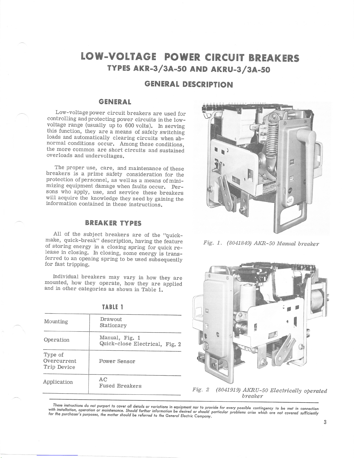
Ali
make, quick-break"
of the
of
storing
lease
in
ferred
for
to an
fast
subject
energy
closing.
opening
tripping.
in
In
GENERAT
circuit
power
up
to
are
a means
clearing
occur.
are
care,
Among
short
and
safety
as
wellas
when
and
service
they need
in
these
TYPES
breakers
descripiion,
a closing
closing,
spring
some
to be used
GENERAT
breakers
circuits
600
of safely
circuits
maintenance
consideration
faults
instructions.
are
having
spring
volts).
circuits
these
and
a means
occur.
these
by
of
the
for
energy
sJbsequenilv
are used
conditions,
gaining
the
for
inthe
low-
In servins
switchin[
when
ab-
sustained
of
these
for
the
mini_
of
per-
breakers
the
"quick_
feature
quick
re_
is trans-
DESCRIPTION
Fig.
(8041849)
1.
AKR-50
Manual
breaker
hdividual
morrnted,
and
in
other
Type
of
Overcurrent
Trip
Device
These
inslruclions
wilh
instollotion'
for
lhe purchoser's
breakers
how
they
categories
do
operdlion
purposes,
may
operate,
as
IABTT I
Drawout
Stationary
Manual,
Quick-close
pvrport
nol
or moinlenonce.
rhe
moner
shown
lo
covsr
shourd
vary
in
how
they
in
Fig.
I
Electrical,
oll
dcloils
should
6e referrd
how
are applied
Table
or
voriolions
furlher
they
L.
Fig.
in
informolion
ri
rhe
c.^irilii".tr;"-t;;;;r:"
are
egurpmenl
bi iesired
Fig. 2
nor lo p.rovide
o,
tno[ii'pirtirutor
(804t9i9)
for
everyposible
pioblams
AKRU-S1
breaker
conlinge
arise
which
Electrically
ncy lo
be mel
nol
in connection
covered
ore
operated
sufficienlly
GEK-731O, Power
Circuit Breokers
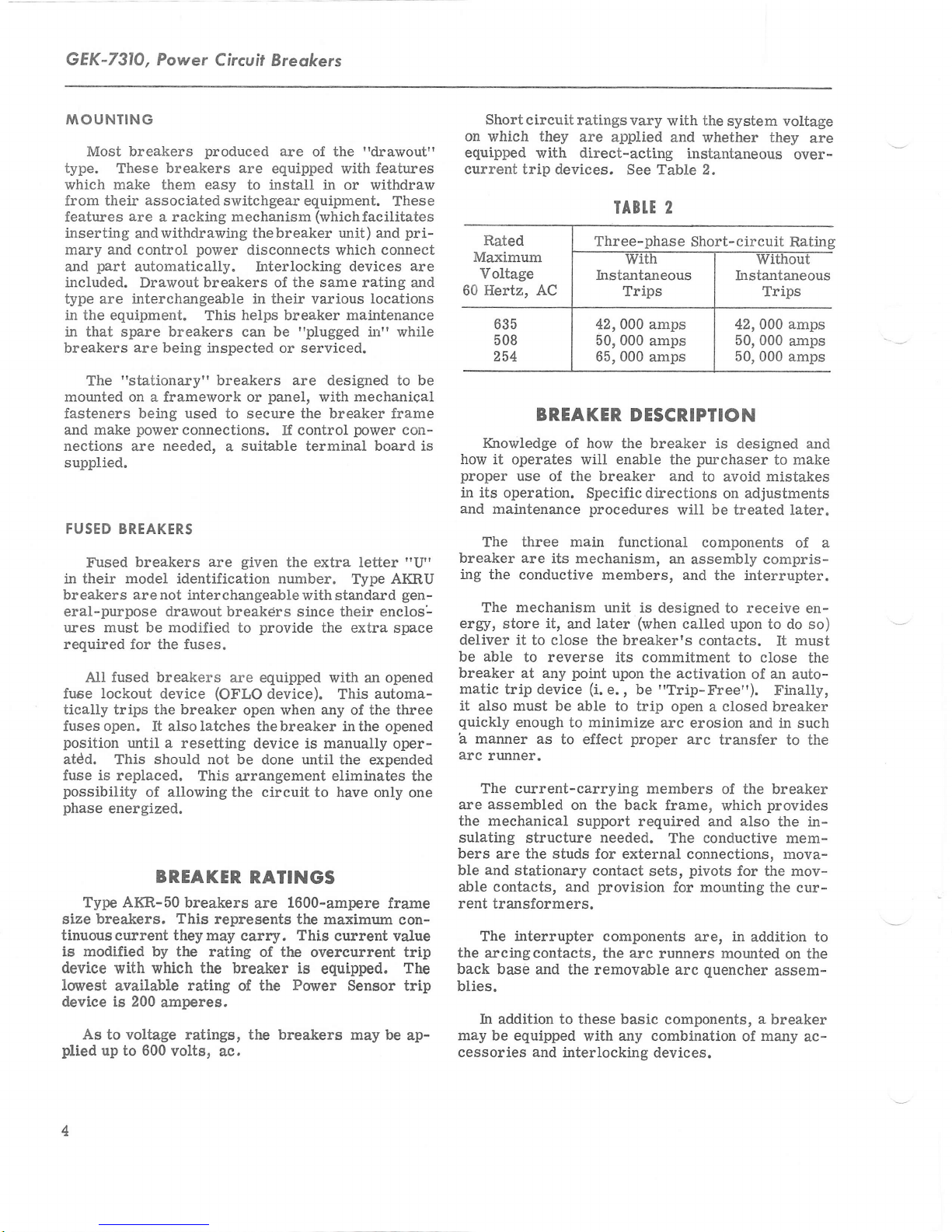
IY\OUNTING
Most breakers
type.
These
which make them
from their
features
inserting
mary
part
and
included.
type are interchangeable in their various
in the equipment. This helps breaker maintenance
associated
are
andwithdrawing thebreaker
and controL
automatically. Interlocking
Drawout
in that spare breakers can
breakers
The
mounted
fasteners being
and make
nections
supplied.
FUSED
Fused
in their
breakers are not interchangeable
are
"stationaryf'breakers
on a framework or
powef
are
BREAKERS
breakers
model identification
produced
breakers are
easy to
switchgear equipment.
a racking mechanism
power
breakers
being inspected or serviced.
used
to secure the breaker frame
connections.
needed.
a
are
are
equipped
install
disconnects
the same rating and
of
be
"plugged
are
panel,
control
If
suitable
given
terminal
the
of the
with
in or withdraw
(whichfacilitates
unit) aad
which
designed to be
with
extra letter
number.
with
standard
"dralvout"
features
These
pri-
connect
devices
mechanical
power
Type
are
locations
in"
while
con-
board is
"LI"
AKRU
gen-
eral-purpose drawout breakdrs since their enclos-
ures must be modified
required for
the fuses.
All fused breakers are
fuse lockout
tically trips
fuses open. It
position
atdd.
is
fuse
possibility
phase
energized.
device
the breaker
alsolatches thebreaker
until
a resetting
should not
This
replaced.
of allowing the
This
BREAKER
Type AIG-50
breakers. This represents
size
tinuouscurrent
breakers
theymay
is modified by the rating
device
lovest
device is 200
plied
with which the breaker is
available
As to voltage ratings, the breakers
to 600
up
rating of the
amperes.
volts,
provide
to
equipped with an opened
(OFLO
device).
open
the extra space
automa-
This
when any of the three
inthe
device is manual.ly
be done until the expended
arrangement
circuit to
eliminates
have
only
RATINGS
1600-ampere
are
the maximum
carry.
ac.
This
of the
Power
current value
overcurrent trip
equipped.
Sensor trip
may be
opened
oper-
the
one
frame
con-
The
ap-
Short
circuit ratings
on which they
equipped
current trip
are
with direct-acting
devices. See Table 2.
BREAKER
IGnowledge
how it
proper
il its
operation.
and
maintenance
operates will
use
of how
of the breaker and
The three main
breaker are
ing
the conductive
The
ergy,
store
deliver
be able
breaker
matic
trip device
it
also
quickly
a
manner as
arc
runner.
The
assembled
are
the mechanical
sulating
bers
are the studs for external connections, mova-
and
ble
able contacts, and
rent
transformers.
The
the
arcingcontacts,
back base and
blies.
In addition to these basic
may
be equipped
cessories and
its mechanism,
mechanism
it,
and
it
to close the breaker's
to reverse its commitment
at any
must
enough
current-carrying
stationary
interrupter
point
be able
to
to effect
on the back
support required and
structure
the removable arc
interlocking devices.
vary
applied
IABI.T
Three-phase
42,000 amps
50,000 amps
65,000
amps
the
with
and whether they
2
system vottage
instantaneous
Short-circuit
42,000 amps
50,000
50,000 amps
DESCRIPTION
breaker
the
enable
is designed and
purchaser
the
to avoid mistakes
Specific
procedures
later
directions
will be
functional
an
assembly
members, and
unit is
designed
(when
called upon to
on
treated later.
components of a
the ilterrupter.
to receive en-
contacts.
(i.
e., be
upon
activation
the
"Trip-Free").
to trip open a closed breaker
minimize
needed.
contact
provision
components are, in
the
with
arc
proper
erosion and in such
arc
transfer
members
of the breaker
frame, which
conductive
The
pivots
sets,
for mounting the cur-
arc
runners
components,
any combination
mounted
quencher
are
over-
Rating
amps
to make
adjustments
compris-
do so)
must
It
to close
of
an
auto-
Finally,
the
to the
provides
also
the in-
mem-
for t}te mov-
addition to
on the
assem-
a
breaker
of many
ac-
Power
Circuit
Breokers,
GEK-7310
RECEIVING,
RECEIVING
breaker is carefully
Each
before shipment. Immediately
circuit
anydamage
handling
immediately with the
nearest
notified.
during unpacking
that no damage
handling, or from exposure to
Check
that no
service
this is not
betakento insuretheproper storage of
breaker,
sustainedin
is evident,
General
is expected that due
It
parts
all
parts
have been overlooked.
is recommended that the
It
immediately in its
possible,
AND
an
examination
a
damage
transportation company
Electric
installation of the breaker so
and
occur
wi.ll
HANDLING
inspected
upon receipt of the
should be made for
transit. If
claim should
Sales
care
from
damage
Office
will
careless or rough
moisture
against the
packing
list to be sure
STORAGE
breaker
permanent
following
the
precautions
HANDLING, AND
1. The breaker should be
packed
and
rough
or
be filed
and the
should be
be exercised
dirt.
or
put
be
into
location.
must
the breaker:
against
warm dry room, since water
verse
ers for outdoor switchgear should
equi.pment only when
heaters are in
2.
cation
ticular care shouldbe
from moistwe
has
If
STORAGE
condensation,
effect on the insulation
operation
breaker
The
free
from
and
a very
CAUTION:
FOR
BE
THAT RUSTING HAS
TO ASSURE
corrosive effect
IF THE BREAKER
ANY
LENGTH
INSPECTED
DITION. SHOULD
preferably
by
absorption
parts.
be
power
should
corrosive
taken to
cement dust, as
PERIODICALLY TO SEE
GOOD
is available
prevent
to
be stored in a clean lo-
gases
or fumes. Par-
protect
this combination
many
on
IS STORED
OF TIME,IT SHOULD
NOT STARTED AND
MECHANICAL
THE BREAKER BE
STORED UNDER UNFAVORABLE AT-
carefully
MOSPHERIC
BE
CLEANED AND DRIED
BEING
CONDITIONS,
PLACED IN SERVICE.
IT
OUT BEFORE
protected
storing
has an ad-
Circuit
stored in the
and
condensation.
the equipment
parts.
CON-
SHOULD
it in
break-
the
a
BREAKER
PUTTING THE
DRAWOUI BREAKERS
mechanism used
The
force required to overcome the resisting force of
disconnects
the
onthebreaker rather than in the drawout
mechanism
This
mechanism
unit
subassembly and
assembled breaker
work on the breaker.
or
BREAKER
to
on Type AKR
IN
SERVICE
provide
breakers is mounted
mechanical
the
enclosure.
is referred to as the
the
"racking"
can be
without doing any disassembly
mechanism. It is a
added to
a completely
"drawout"
This drawout mechanism consists of a crank-
power
a
and
shaft
fastened to each end of the crankshaJt is
having
arm
in the equipment enclosure.
tates, the crank arms, acting on the stationary
cause
the breaker to move
enclosure.
screw
an open slot
crankshaft
The
which operates
which
with respect to the
engages a fixed
the crankshaJt ro-
As
it.
is driven as the
Rigidly
a
crank
pin
pin,
breaker
power
OPERATION
screw
supported by a centrally located
shaft. The
by means
crank.
will engage the square end of the
breaker. A
be moved aside
screwshaft
clockwise direction moves the breaker into
nected
breaker to move
BREAKER
drawout enclosure
even coating
bars inthe
connects
is turned in an internally
power
screw,
of an external
has,
This
sliding cover in the escutcheon must
end.
position.
|NSERI|ON
procedure
The
1. Before inserting
of D50H47
enclosure
the
of
its
on
so that the handle may engage the
Turning the crank handle in a
reverse
The
out.
(FtG.
for inserting
as
is
the breaker, apply
whichengagethe
breaker.
crank on
jackscrew,
or
handle
a square socket
end,
power
of
3)
a
follows:
grease
to the silver-plated
threaded trunnion
the crank-
is turned
in the form of
which
screw in the
the con-
this
causes the
breaker into its
light,
a
primary
dis-
a
GEK-731O,
Power
Circuif
Breokers
5.
Extend the second rail.
6. Align the
in the rails and
ing
go
move
pins
the
all the
the lifting device.
7. Make
the trip button.
move
the sLiding
racking
clockwise
and remove
remove
the ends of the rackingshaftso that theywill engage
the
has not been
the encloswe, the
to
handle.
8.
itispossibletoturn
If
it. This step is taken to
pins
in
engage
the
pins
on the breaker
carefully
lower
to enter their slots. Make sure the
way down to the bottom of the slots; re-
sure the
breaker
While
is open by
holding in the
with the slots
the breaker, allow-
trip
pins
pushing
button,
cover aside and then engage the
handle
direction, do so
handle.
the
housing.
the
operated while the
pins
andthis stepwillnotbe
If the
arms
will be in theright
the
until
handle
If the racking
in
counter-
the stop is reached
align
breaker is
a
not
does
the arms
mechanism
position
necessary.
turn,
on
out of
9. Make sure that latches on the ends of the ex-
tended
pushing
into the enclosure.
rails are in the unlatched
on the breaker, roll it
position,
as
far
as
and
it will
by
go
10. Put the latches on the ends of the rails into
their locked
position.
in
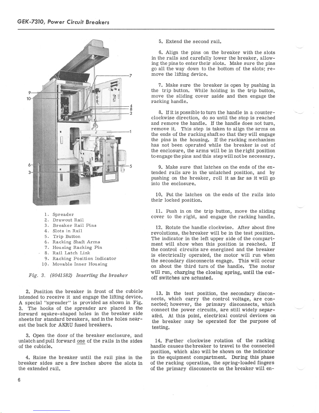
I.
Spreader
2. Drawout Rail
3. Breaker Rail
4. Slots
'
10. Movable
Fig. 3.
5. Trip Button
6.
7. Housing Racking
B. Rail
9.
(8041582)
in
Racking Shaft
Latch Link
Racking
2. Position the breaker
intended
A
3.
forward
sheets for standard
est
unlatchandpull forward
of the cubicle.
breaker
the extended
to receive it and engage
special
The
the back for AKRU fused
3.
4.
"spreader"
hooks of the
square-shaped
the door of the
Open
Raise
the
sides are
breakers,
breaker
a few inches above the slots
rail.
Pins
Rail
Arrns
Pin
Position Indicator
Inner Housing
Inserting
provided
is
spreader are
holes
one of the rails inthe sides
until the rail
the breaker
in front of
lifting device.
the
as shown
placed
in the breaker
and inthe
breakers.
breaker
encloswe,
the cubicle
in
holes near-
pins
Fig.
in the
side
and
in
the
11. Push in on the trip button, move the sliding
cover to the right,
12.
Rotate
revolutions, thebreaker
indicator
The
ment
will
control
the
the
show
circuits
is electrically
secondary
the
on about the third turn
run,
will
off switches
13.
nects,
nected;
connect the
atbd.
the breaker
testing.
charging the
are
h the test
which carry the control.
however,
power
this
At
and engage the racking
handle
left upper
the
in
when this
are
operated, the
disconnects engage.
closing spring, until the
actuated,
position,
primary
the
circuits, are
point,
may
electrical
be operated
14. Further clockwise
handle causesthebreaker to travel
position,
in the
of the racking operation,
in
of the
which also
equipment
primary
will be
compartment. During
disconnects on
handle.
clockwise. After about five
be in the test
will
side of the
position
energized
motor
the handle.
of
and
This
position.
compart-
is reached. If
breaker
the
run when
will
will occur
motor
The
cut-
the secondary discon-
voltage,
disconnects, which
are
con-
still widely separ-
control
for the
rotation of
shown on the indicator
the spring-loaded
the
devices on
purpose
the
racking
to the connected
phase
this
fingers
breaker will en-
of
6
gage
the
stationary bar
The opening of these fingers
springswill
ment
in the racking
fali
off
travel,
About
peak
the
which
the
handle
sal
of the handle motion. Approximately
on the handle
ing cycle.
15.
The first
the enclosure,
and
the marks
grease
tracks
engagement.
attained
BREAKER
cause a noticeablyhigher
to
a lesser force requirement
at which
point
three handle
force requirement
the
ends
movement.
should be removed
are required
time the breaker
it
should
the
of
on the
marks
is
stationary
should
The maximum
g/16-inctr.
WITHDRAWAL
the
in
equipment
against the
effort. This will
a stop will be
turns
will be required
and reaching
Upon
without
for the
be completely
disconnect
bars examined.
indicate no less
amount
enclosure.
force
require-
load
quickly
very
to
the
encountered.
between
the stop
reaching
the
any rever-
24 turns
complete rack-
is introduced
withdrawn
fiagers
than
that
on the
1/4-inch
can
of the
end of
stop,
into
These
be
ers.
They should
easily
enough
the area
Iocation
ject
of the
switchboard
tions
connections
iliary
mountingholes
fastens
vertical
posed
versely
ouiline
gives
and
to
reached
surrounding
is not
chosen
to
extreme
Mounting
breaker to
tothebreaker
to the
switch
the frame
These mounting
plane.
on the breaker
a-ffect
drawing
information
a
cover
parts
live
Power
Circuit
be
situated
for
operation and
free space
troublesome.
should bedry
variations
the
breaker
its supporting
or
enclosure,
studs, andmaking
breaker
terminals,
are
If they
the
which is
or door
of the breaker.
if
required
to its
support.
holes
are not,
structure
operation
preparing
on
suitable
Breakers,
so
that
maintenance,
so
that
If it is
andclean
of temperature.
involves
terminal
these
must
furnished
bolting
structure
making
power
board and
are required.
forthe hardware
all be in
strain may
which could
of the
with the breaker
a mounting
preventing
for
GEK-731O
they can
working
possible,
andnot
the
within
connec-
control
power
the same
be im-
breaker.
structure
access
be
with
in
the
sub-
frame
the
arx-
Four
which
ad-
The
1. Trip
ton,
and move
aside to
2.
counterclockwise
the breaker
the
right.
Engage
the
sliding
the racking
direction.
3. ApproximateLy
complete the
breaker to
shown
be
because
on the
evident to the
further
the
of
racking
willbe
to discharge,
latches
out
Iifted
STATIONARY
activated.
4.
To
onthe
of the compartment.
off the
racking-out
the disconnected position.
indicator
person
stop will
a
movement
be
can
cycle,
This
but
will not
withdraw the
ends
ofthe rails,
rails
by the
BREAKERS
Stationary breakers are
mounting
in an
construction.
the drawout
drawout
and automatic
Careful
lection
on
a framework
enclosure
They
type; however,
features,
disconnects
consideration
a location
of
of the
namely,
for
hold
open,
cover in the
handle
24 turns
operation
in the
operating
encountered
be made.
the
"closing
in
and
the
of
compartment
the mechanism
beyond
Towards
spring
willcause theclosing
close the
breaker
The
lifting
intended
breaker.
completely,
pull
and
breaker
device.
or switchboard
customerts
are the same
own design
breaker unit
they do not have
the
racking mechanism
and
interlocks.
should be
mounting
given
stationary
the trip
escutcheon
crank
handle
and bring the
This
but-
in a
wiII
will be
and will
which no
the
end
interlock"
spring
open the
thebreaker
may now
for
panel,
to the se-
be
separate
or
and
as
the
break-
Another
for
the breaker
stand
and
short-circuit
be subjected.
supportedadequately
of support
enough
is
imposed
Manual
ance is
is
operated.
to the
2-l/2
frame.
Since eachupper
of two
stud must
parallel
nection.
connector
with
and lower
cable
connects
connectorb:rrs
the end
wards
yond
the
Control
made
frontarea
board
governedby
requirement
is that
the forces
Connectingbus
for buswork
to the
provided
right
arches
separate
connectors
the breaker
to a terminal
may have
breaker
on
the breaker's
breakers
for
This
from
beyond
provide
stud members,
All
members,
stationary
bars
studs.
across
of the
centerline
both halves
may
connecting
connections
of thebreaker
6, 10
the
requirements
that
currents
or busbars.
of
the supporting
it be
rigid
result
from high
to
which thebreaker
or cable
to
resist
these
or cable
so
that no
must
be located
the sweep
requirement
the centerline
the right
studof
a
solid connection
as
appreciable
studs.
of the handle
will be
of
edge
thebreaker
the
connections
well as
breakers
already fastened
These bars
will
If an
of the upper
bedispensed
base no more
the
of
fastener
on stationary breakers
board
located
(front
or 14
with.
bus
should extend in
than 5/8-inctr
hole.
in the upper
view).
points.
of the
structure
enough
forces.
must
to
momentary
must
also be
points
be
strain
so that
the breaker,
of the
11 inches
breaker
is
composed
clear-
when it
to the
across
an external
will
the two
be shipped
to both
accommodate
upper
external bar
studs,
hthis
The terminal
This
control
will
scheme.
with-
may
close
or
con-
the
case,
to-
be-
are
left
be
GEK-731O,
Power
Circuit Breokers
If the breaker
connections
of
switch.
the
PRE-SERVICE CHECK
Before
first time, it
amination
of the breaker.
breaker
an equipment
should consist
1. Attach
onthebreaker afterpushing
ing the cover aside.
til it
Iocks
closing.
and a
on
stops.
which otherwise
has an
may be made
putting
the breaker
would be
preliminary
This
a
workbench or
drawout
the
of
following:
thedrawout
Turn the
This will
auxiliary switch,
well to
may
compartment.
racking handle
deactivate
would keep the breaker
NOTE: Remember, later,
chanism must
position
serted in the
2.
Remove the arc
examine
parts.
the
it for the
Do
preliminary
not
be set
before the
equtpment.
quencher
possibility
replace the arc
examination
directly
be carried
on
thetrip
to the terminaLs
into
service for the
make a
check
the
handle
cursory ex-
the
of
out with the
extended rails
to the shaft
button
clockwise
the various inter-
that this
back to
breaker
i,ts
original
can be in-
from each
of broken or missiqg
quenchers
is
completed.
external
operation
of
The check
slid-
and
un-
from
me-
pole
and
until after
move in
seem
this, refer
tiiled
ping
tivate
Devices
overload
voltage
("wipe")
to
do so, and
at
to the section
"CONTACT
5.
Make
breaker open Erre
the
thesewith thebreaker
in
devices,
device.
6. If the
MAINTENANCE.
swe that a-ll the devices
category are the
this
the
breaker is
the operation of the
Iifting interlock
that
breaker and that the
not be opened if the
the closing
is charged,
far as itwill
as
7.
securely.
8.
should be checked when
ers
able,
drawout equipment
spring
and
Replace
electrical operation
The
with the
wiII
drawout
the
go
inthe counterclockwise direction.
the
breaker in the
least
1/16 inch.
careful measurement
If they do not
of these instructions
"
used for trip-
operable.
closedto establish
shunt trip,
a
drawout breaker, check
Manually ac-
manual trip, the
and the under-
interlock devices. Make
(3),
pin
sliding cover
breaker is closed.
discharge automatically
racking handle is cralked
quenchers,
arc
Fig.
4,
will trip the
(1),
Fig.
Check
clamping
of electricai break-
"test"
power
position
control
compartment.
confirms
en-
this.
sure
8 can-
that
if it
them
is avail-
in the
3.
Charge
manually
as
far as it
motion
and
the closing
operated, turn the handle
(140
go
will
rdturn
it to the vertical
breaker is electrically
nance handle,
charges the
NOTE: It
align the triangular
make it
4.
Close
closed by
eon.
The
closed by
closing
chanism
tangular
This
move
the stationary
and
solenoid which is located beneath
opening
maybe
in closing
Observe
when it is
Fig. 5, to
ciosing
go
the breaker.
pushing
"quick-close"
pulling
and
may bereached throughthe large
done safelysince none
the difference between
spring.
probably
on the
the
CLOSE
forward
in thelower
in this area.
are
contacts
closed.
spring. If the breaker is
degrees), then
eounterclockwise
reverse the
position.
operated,
use
the
turn the camshaft which
nill be necessa',ry to
socket
end of
electrical
when the breaker is
The
in the handle to
the
shaft.
manual breaker is
The
button
on the
end of the escutcheon.
main
in the escutch-
breaker may
armature
parts
the
of
(See
Fig.
position
the
contacts should
If the
mainte-
be
of the
me-
the
rec-
that
64,.)
opened
A breaker may
manually
result in the same
as the
is in the rpay energy
how i.t is released.
and
'NANUAt
Manually
front-mounted
with
the mechanism
sets
spring.
either cranking
degree
The CLOSE
to close
used
button to open
If
of
equipped
breaker
relay.
or
OPERATING
THE BREAKER
be equipped to
or electrically. Both
fast-closing movement as far
contact
swing) or
may beclosed remotelyby a
action is concerned. The variation
is stored in theclosing spring,
CLOSING
operated
AI(R breakers
handles. Handle
and
A complete charge
handle
the
three cycles
the
them.
with
mounted
breaker
closing solenoid, a
a
button,
Before this can be
charges
fully
is
through
(50-degree
on
contacts and
done, however, the
operate either
types of operation
constructed
are
operation re-
the closing
accomplished in
one cycle
the escutcheon,
(135-
swing).
the TRIP
manual
control
switch
is
8
Power Circuit
Breokers, GEK-731O
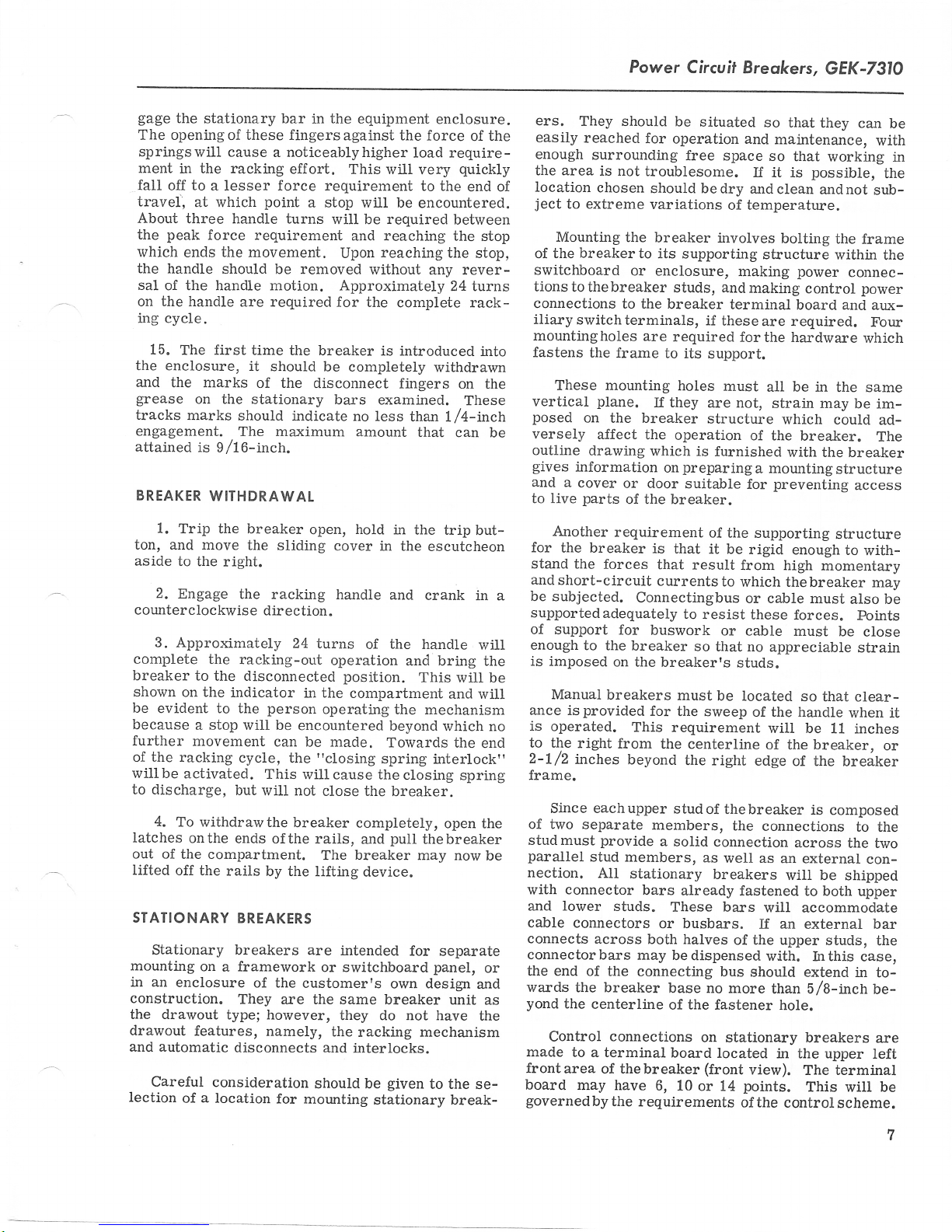
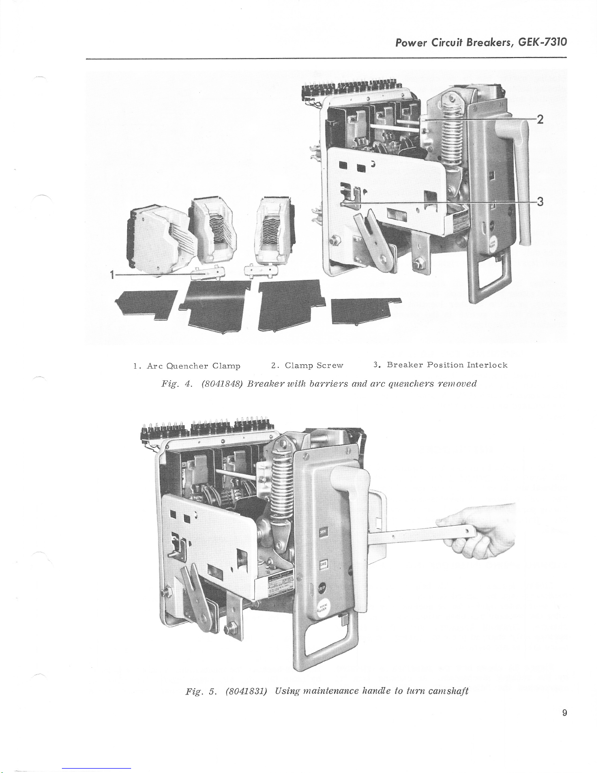
1. Arc
Quencher
Fi.g. 4.
Clarnp
(8041848)
Z. Clarnp Screw
Breaker with bqrriers
3. Breaker Position
and arc
quenchers
Interlock
remoued
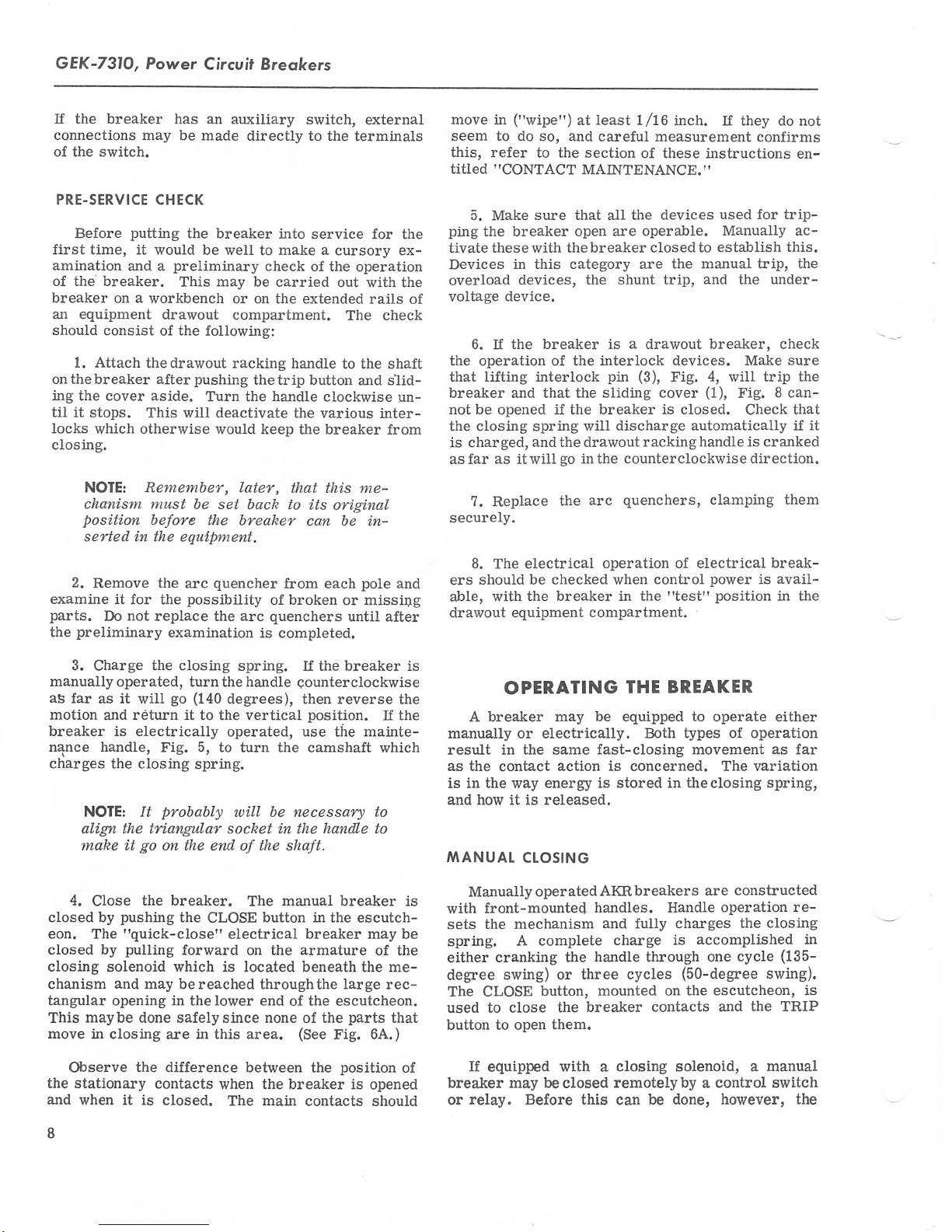
Fig. 5.
(8041831)
maintenance handle
Using
to turn
camshaft
GEK-731O, Power
Circuit Breokers
closing spring has to
closing solenoid is
supplied unless specified in the breaker
ELECIRICAL
Applying
the closing motor
the motor
of
spring is completely
spring
the closing
leases
Apush-button
CTOSING
control
circuit
is mechanically
circuit activates a
holding latch.
the
closing
electricalbreakers.
vided
only ifspecified in
plied,
it is located
When
closed
motely,
the
breaker is
either
or at
push
inthe right
in service,
by
energizing the closing
the
button
switch
so equipped).
OPENING
A closed breaker
trip latch
the secondary latch
are mounted
device.
(11),
Fig. 12, is moved
on the trip shaft,
be charged by
optiona-l
an
power
on electrical
does not
charged and
held from discharging
This
the breaker
accessory
immediately
breakers.
occur until a-fter the
overcenter. The
solenoid
switch
may
feature,
be
however, is
order. If sup-
side of the escutcheon.
all electrical breakers
breaker location
in the
THE
BREAKER
will
open
(14).
A number of trip
by
escutcheon
(trip)
off the
one for each tripping
hand. The
is not
and
order.
energizes
Cutoff
which re-
provided
circuit
operation of
(if
whenever
roller on
paddles
until
on
pro-
are
re-
ttre
the
\ri
/-
"l
a\^.
\
\N
\\l
It\
tl
12
Fig.
6A.
a\
t\
\'\
\-
f..
I
.rm
(227A8290)
Closi.ng
spri.ng
interlock
INTERTOCKS
interlock
Some
Standards
optional
standard interlock devices described in the fol-
The
Iowing
ers.
locks.
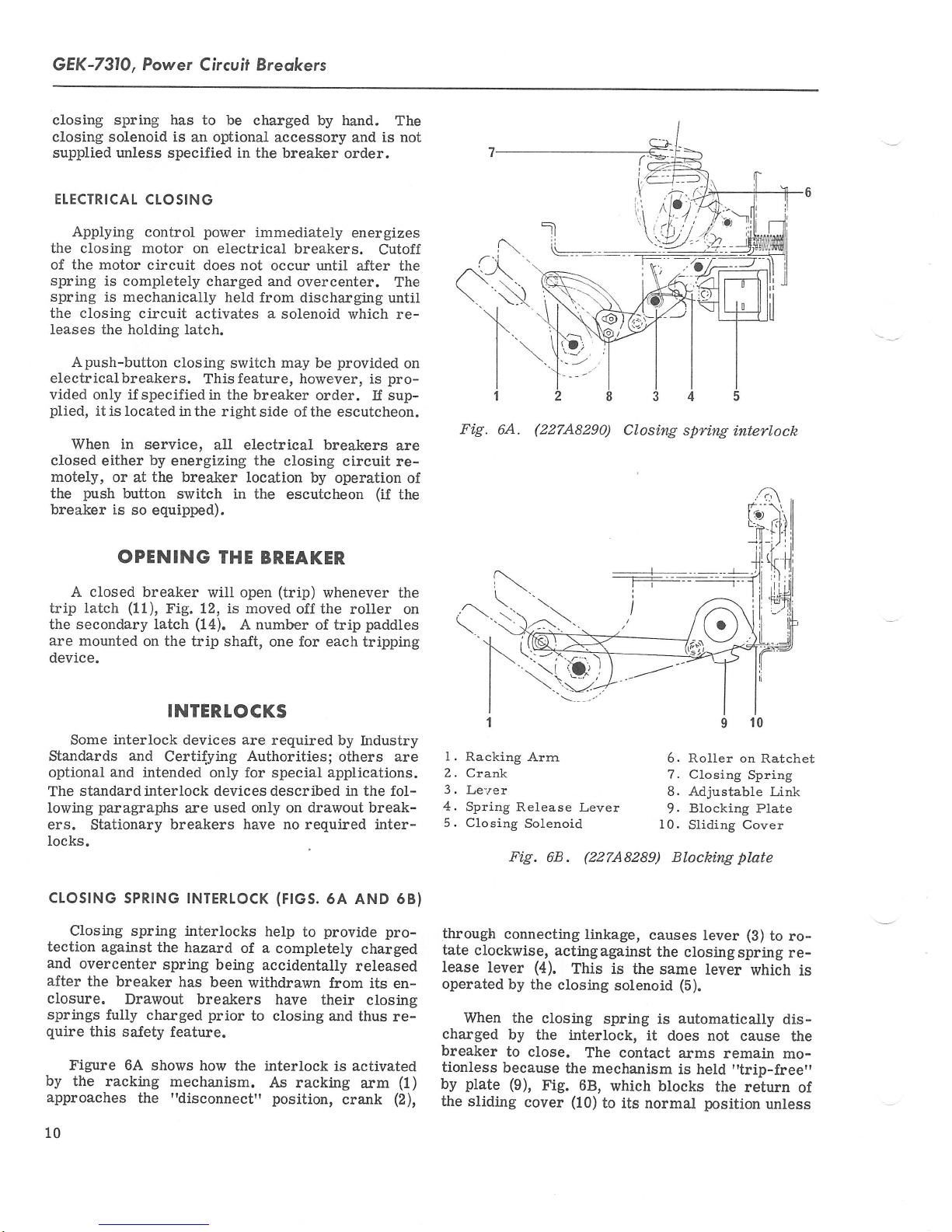
cLoSrNG
Closing spring interlocks
tection
and
overcenter
after
closure.
springs
quire
Figure 6A shows
by
the racking
approaches
10
and
and
paragraphs
Stationary
SPRTNG
against
the breaker
Drawout breakers
fully charged
this
sa-fety
devices are
required by
Certifying Authorities;
intended only for
used only on drawout break-
are
breakers
INTERTOCK
the hazard
spring
has
feature.
mechalism.
the
"disconnect"
have no
of a
being
been
withdrawn
prior
to closing and
how
the interlock
help
accidentally
As
special
(F|GS.
completety
have
applications.
required inter-
6A AND 68)
provide
to
from
their
is
racking
position,
Industry
others are
pro-
charged
released
its en-
ciosing
thus re-
activated
(1)
arm
crank
(2),
I
'l
l.
Racking
2. Crank
3.
Le:'er
4.
Spring
5. Closing
through
tate
clockwise,
lease
lever
operated
When the
charged
breaker
tionless
plate (9),
by
the
sliding
Arrn
Release
Solenoid
Fig.
68.
connecting
actingagainst
(4).
by
the
closing
closing
by
the interlock,
to close.
because
the mechanism
Fig.
cover
Lever
(22748289)
linkage,
This is
The contact
68,
(10)
the same
solenoid
spring is
which
to its
6. Roller on
7.
Closing
8. Adjustable
Blocking Plate
9.
10.
Sliding
Blocking
causes
lever
the
closingspring
lever
(5).
automatically
it
does not
arms remain
is held
blocks
normal
position
10
Ratchet
Spring
Link
Cover
plate
(B)
to
which is
dis-
cause the
mo-
"trip-free"
the return
unless
rore-
of
Power
Circuit
Breokers,
GEK-731O
breaker
the
nected"
within
inaccessible,
accident.
RACKING'NECHANISIYT
(FtG.
8)
A drawout
not be
must
contacts
automatically
the escutcheon
Unless
inghandle
link
by
in the cover
the closed
Another
that the
manual trip
the
keeping the
of the
ment of
Iong as the
Another
interlock. This
is in the
position.
mechanism
the
This
minimizes
and
breaker connected
allowed
to
are open. This
locking closed
the breaker
when
cover
this
cannot be
(2),
Fig.
ia response
positi.on.
aspect of
openingmovementof
breaker
mechanism
the contacts. This
drawout
interlock
used. Lockingisaccomplished
8
which
button
"trip-free",
will
handle is engaged.
featwe
makes thebreaker
"test"
limits
frame,
position
motion to
which
the
INIERLOCKS
to a
move unless
requirement
the
is closed.
is moved,
to the
the interlock
the drawout
moves
down
main
the slidingcover
into the tripped
so a closing
not cause
any closing
condition
is the
or the
are
possibility
power
the breaker's
sliding
"con-
those
relatively
circuit
met by
is
cover
parts
of
rack-
into a notch
being
shaft
arrangement
cams
position'
cycle
move-
prevail
will
breaker
position
"trip-free"while
moving between the
nected"
between these
an
which
the
This
keeps the breaker open even
position.
two
is coupled to the trip
"ramp"
cam
holds the mechanism latch out of
are discharged.
OPTIONAT INTERTOCKS
optional
in
in
is
as
The
interlocks.
door
mounted in the equipment
are
vices
the breaker
Iock
the
sition.
all breakers,
On
lock the breaker
to
padlock
the
in
slot
trip button
cannot be closed.
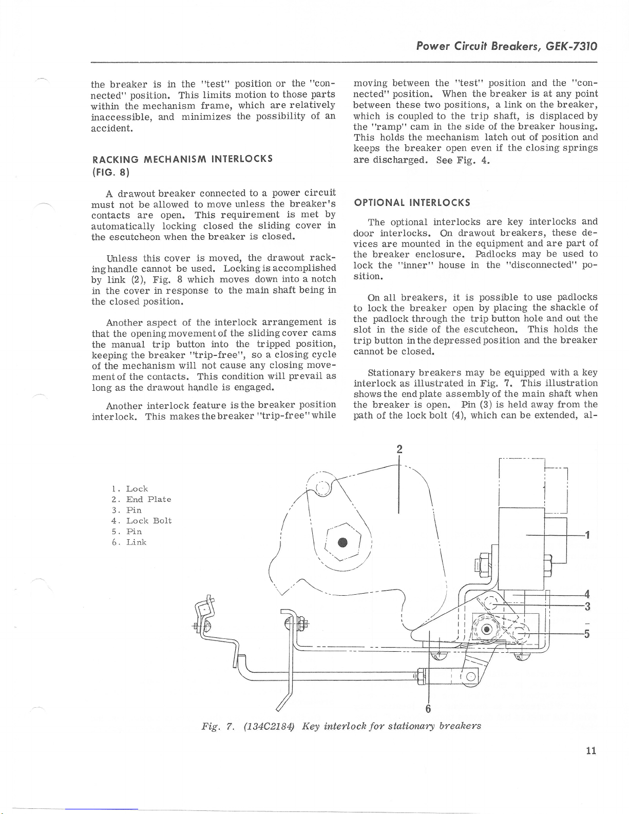
Stationary
interlock
the
shows
the breaker is open. Pin
path
of
enclosure. Padlocks
t'inner"
through
side of the escutcheon. This
the
inthe depressedposition and
breakers
illustrated in Fig.
as
plate
end
the lock bolt
"test"
When
positions,
position
the breaker is
a link on the breaker,
shaft, is displaced by
in the side of
if the closing
See Fig.
interlocks are
On
house in the
assembly
4.
drawout breakers.
possible
is
it
open by
placing
the trip button
may be
of the
(3)
(4),
is held away from the
which
the
and
the breaker
interlocks
key
and
may
"disconnected"
use
to
the shackle
hole
equipped
7.
This
main
can be extended,
"con-
at
any
housing.
position
springs
these de-
part
are
be used to
padlocks
and
out the
holds the
the breaker
with a
illustration
shaft
point
and
and
of
po-
of
key
when
aI-
1 . Lock
End Plate
2.
3. Pin
4. Lock BoIt
5. Pin
Link
6.
Fig. 7.
i
)
\
(134C2184)
Key inteflock
stati.orwrl
for
-t-
\
\
\
\
\
I
6
breahers
11

GEK-7310,
Power Circuit
Breokers
l.
Sliding
lowing
makes it
this
sible
sembly
causes
bolt, which cannot
breakers
used
Minor differences in
exist, but most of the devices
the key to be removed. Extending
push
moves
against
breaker latch, and
the
pin
(5).
to close the breaker.
When
is
away
(3)
pin
Accessories
from link
to move into the
then be extended.
ACCESSORTES
available
(6)
for use on the AIG-50
breaker is closed, the
the
are, in most cases, the same devices
throughout
the entire line of AK
mounting and location may
tical.
L2
Cover 2. Locking Link
Fig. 8.
(134C2179)
Drawout interlocks
the bolt
Through
the
makes it impos-
linkage,
placing,
dealt
structions; only
function it serves
SHUNT TRIP
and
metal
torsion spring
the
path
of the
plate
lock's
as-
its coil
which
in series with
made
ondary disconnects
arxiliary switch and
breakers.
bottom
themselves
breakers.
are
iden-
3. Trip
Maintenance operations, such
adjusting
and
in
with
The
is
the
shunt trip device opens
energized.
is
closed only
Button
these components wili be
maintenance
description
a
be
will
dealt with
An
when the breaker
portion
the device
of
the breaker when
frA't
the device coil.
the external tripping source
to
on
drawout
breakers, or to the
terminal board on
the breaker,
On
the
of
breaker frame in
the
shunt
trip
a
as adding, re-
of these in-
and
the
here.
auxiliary switch,
is
closed,
Connections
through sec-
stationary
is mounted
central location.
are
on the
is
 Loading...