

Page 1

SAFETY INFORMATION .........3
USING THE AIR
CONDITIONER ..............4
OWNER’S MANUAL &
INSTALLATION
INSTRUCTIONS
CARE AND CLEANING ...........7
INSTALLATION
INSTRUCTIONS ...............8
TROUBLESHOOTING TIPS ......17
CONSUMER SUPPORT
Warranty ............................19
Consumer Support ................... 20
24” Through-the-Wall
Cool Only Models
AKCQ08A
AKCQ10A
AKCQ10D
AKCQ12A
AKCQ12D
AKCQ14D
Heat/Cool Models
AKEQ10D
AKEQ12D
AKEQ14D
ESPAÑOL
For a Spanish version of this
manual, visit our Website at
www.GEAppliances.com.
Para consultar una version
en español de este manual
de instrucciones, visite nuestro
sitio de internet
www.GEAppliances.com.
Write the model and serial
numbers here:
Model # _________________
Serial # _________________
You can find the this information
on a label attached to the right
side of the chassis.
For a French version of this
manual, visit our Website at
www.GEAppliances.ca.
Pour un version français de
ce manuel d’utilisation, veuillez
visiter notre site web à l’adresse
www.GEAppliances.ca.
FRANÇAIS
AIR CONDITIONER
GE is a trademark of the General Electric Company. Manufactured under trademark license.
49-5000444 Rev. 0 01-20 GEA
Page 2

THANK YOU FOR MAKING GE APPLIANCES A PART OF YOUR HOME.
Whether you grew up with GE Appliances, or this is your first, we’re happy to have you in the family.
We take pride in the craftsmanship, innovation and design that goes into every GE Appliances
product, and we think you will too. Among other things, registration of your appliance ensures that we
can deliver important product information and warranty details when you need them.
Register your GE appliance now online. Helpful websites and phone numbers are available in the
Consumer Support section of this Owner’s Manual. You may also mail in the pre-printed registration
card included in the packing material.
2 49-5000444 Rev. 0
Page 3

IMPORTANT SAFETY INFORMATION
READ ALL INSTRUCTIONS BEFORE USING THE APPLIANCE
SAFETY INFORMATION
WARNING
■ Use this appliance only for its intended purpose as
described in this Owner’s Manual.
■ This air conditioner must be properly installed in accordance
with the Installation Instructions before it is used.
■ Never unplug your air conditioner by pulling on the
power cord. Always grip plug firmly and pull straight
out from the receptacle.
■ Replace immediately all electric service cords that
have become frayed or otherwise damaged. A
damaged power supply cord must be replaced with a
new power supply cord obtained from the manufacturer
and not repaired. Do not use a cord that shows cracks
or abrasion damage along its length or at either the
plug or connector end.
WARNING
RISK OF FIRE. Could cause serious injury or death.
■ DO NOT use an extension cord with this air
conditioner.
For your safety, the information in this manual must be followed to minimize the risk of
fire, electric shock or personal injury.
USE OF EXTENSION CORDS
■ Turn the unit OFF and unplug your air conditioner
before cleaning.
■ For your safety…do not store or use combustible
materials, gasoline or other flammable vapors or
liquids in the vicinity of this or any other appliance.
■ If the receptacle does not match the plug, the receptacle
must be changed out by a qualified electrician.
■ DO NOT use surge protectors or multi-outlet
adaptors with this air conditioner.
HOW TO CONNECT ELECTRICITY
Do not, under any circumstances, cut or remove the third
(ground) prong from the power cord. For personal safety,
this appliance must be properly grounded.
DO NOT use an adapter plug with this appliance.
The power cord of this appliance is equipped with a
3-prong (grounding) plug which mates with a standard
3-prong (grounding) wall outlet to minimize the possibility
of electric shock hazard from this appliance.
Power cord includes a current interrupter device. A test
and reset button is provided on the plug case. The device
should be tested on a periodic basis by first pressing the
TEST button and then the RESET button while plugged
into the outlet. If the TEST button does not trip or if the
RESET button will not stay engaged, discontinue use of the
air conditioner and contact a qualified service technician.
For appliance recycling information please visit GEAppliances.com/recycling.
Have the wall outlet and circuit checked by a qualified
electrician to make sure the outlet is properly grounded.
Where a 2-prong wall outlet is encountered, it is your
personal responsibility and obligation to have it replaced
with a properly grounded 3-prong wall outlet.
The air conditioner should always be plugged into its
own individual electrical outlet which has a voltage rating
that matches the rating plate.
This provides the best performance and also prevents
overloading house wiring circuits which could cause a
fire hazard from overheated wires.
See the Installation Instructions, Electrical
Requirements section for specific electrical connection
requirements.
READ AND SAVE THESE INSTRUCTIONS
49-5000444 Rev. 0 3
Page 4
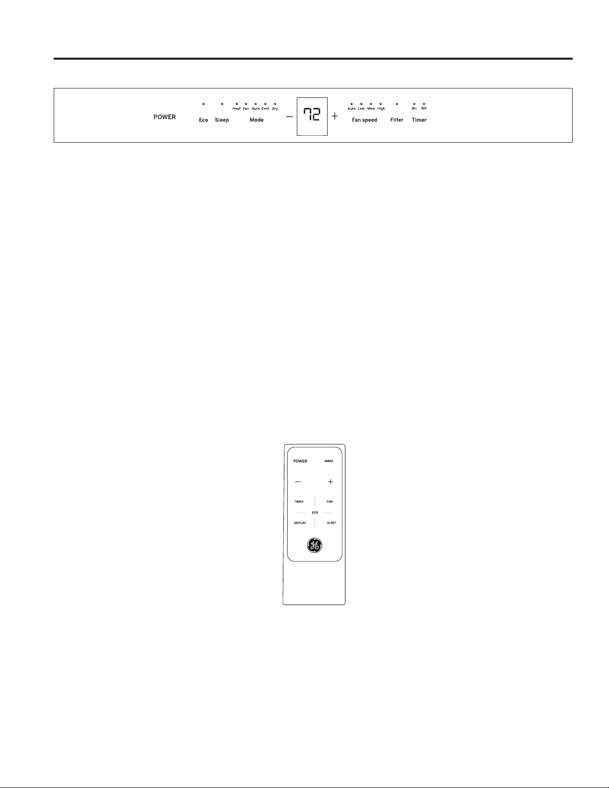
Using the Air Conditioner - Controls
Appearance may vary.
Temp/Timer
Air Conditioner Controls
Lights above the touch pads on the air conditioner
control panel indicate the selected settings.
1. POWER
Turns air conditioner on and off.
2. Display
Displays the temperature setting. Displays hours when
setting the timer.
3. Mode
Use to set COOL, HEAT (on some models), DRY, AUTO,
or FAN modes. Indicator lights on the controls will show
the mode selected.
USING THE AIR CONDITIONER
4. Temp Increase + / Decrease - Pads
Use to set temperature when in Auto, Cool, Dry or Heat
(on some models) mode.
5. Fan Speed
Use to set the fan speed at LOW, MEDIUM, or HIGH.
Indicator lights will show the speed selected.
6. Timer
ON - Use to set the air conditioner to automatically turn ON
from .5 to 24 hours later.
OFF - Use to automatically turn the air conditioner OFF
from .5 to 24 hours later.
7. Filter
Monitors accumulated fan run time as a reminder to clean
the filter.
8. Eco
ON: Use to cycle the fan off when the compressor cycles
off.
OFF: Use to run the fan continuously when in cooling or
heating (on some models) mode.
9. Sleep
Allows room temperature to increase (Cool mode) or
decrease (Heat mode) during sleeping hours.
Remote Control
■ To ensure proper operation, aim the remote control at
the signal receiver on the air conditioner.
■ The remote control signal has a range up to 21 feet.
4 49-5000444 Rev. 0
■ Make sure nothing is between the air conditioner and
the remote control that could block the signal.
■ Make sure the battery is fresh and installed correctly—
see the Care and Cleaning section.
Page 5

Using the Air Conditioner - Features
To Adjust Fan Speeds
Press the Fan Speed button to select the FAN Speed
in four steps - Auto, Low, Med, or High. Each time the
button is pressed, the fan speed mode is shifted.
Sleep
Press the Sleep button to initiate the sleep mode. In this
mode the selected temperature will increase (cooling)
or decrease (heating) by 2°F / 1°C 30 minutes after the
mode is selected. The temperature will then increase
(cooling) or decrease (heating) by another 2°F / 1°C after
an additional 30 minutes.
Check Filter
Press the Filter button to initiate this feature. This feature
is a reminder to clean the air filter for more efficient
operation.
Eco - Energy Saver
Press the Eco button to initiate this feature. This feature
is available on COOL, DRY, AUTO, (only AUTO-COOLING
and AUTO-FAN) modes. The fan will continue to run for 3
minutes after the compressor shuts off.
For some models, the fan speed can not be adjusted
under HEAT mode. In DRY mode, the fan speed is
controlled at low automatically.
This new temperature will be maintained for 7 hours
before it returns to the originally selected temperature.
This ends the Sleep mode and the unit will continue
to operate as originally programmed. The Sleep mode
program can be cancelled at any time during operation
by pressing the Sleep button again.
The LED (light) will illuminate after 250 hours of
operation. To reset after cleaning the filter, press the Filter
button and the light will go off.
The fan then cycles on for 2 minutes at 10 minute
intervals until the room temperature is above the set
temperature, at which time the compressor turns back on
and Cooling starts.
USING THE AIR CONDITIONER
To Select the Operating Mode
To choose operating mode, press the Mode button.
Each time you press the button, a mode is selected in a
sequence that goes from Auto, Cool, Dry, Heat (on some
models) and Fan only. The indicator light above will be
illuminated and remain on once the mode is selected.
The unit will initiate the Energy Saver function under
Cool, Dry, Auto (only Auto-Cooling and Auto-Fan) modes.
To Operate on Auto Feature:
■
When you set the air conditioner in AUTO mode, it will
automatically select cooling, heating (on some models)
or fan only operation depending on what temperature
you have selected and the room temperature.
■
The air conditioner will control room temperature
automatically to the temperature set point.
■ In this mode, the fan speed cannot be adjusted, it starts
automatically at a speed according to the room temperature.
To Operate on Fan Only:
■ Use this function only when cooling is not desired. You
can choose any fan speed you prefer.
■ During this function, the display will show the actual
room temperature, not the set temperature in the
cooling mode.
■ In Fan only mode, the temperature is not adjustable.
To Operate on Dry Mode:
■ In this mode, the air conditioner will generally operate in
the form of a dehumidifier. Since the conditioned space
is a closed or sealed area, some degree of cooling will
continue.
Timer: Auto Start / Stop
■
When the unit is on or off, first press the Timer button,
the TIMER ON indicator light illuminates. It indicates the
Auto Start program is initiated.
■ When the time of TIMER ON is displayed, press the
Timer button again, the TIMER OFF indicator light
illuminates. It indicates the Auto Stop program is initiated.
■
Press or hold the UP or DOWN button to change the
Auto time by 0.5 hour increments, up to 10 hours, then
at 1 hour increments up to 24 hours. The control will
count down the time remaining until start.
49-5000444 Rev. 0 5
■
The selected time will register in 5 seconds, and the
system will automatically revert back to display the
previous temperature setting or room temperature when
the unit is on. (When the unit is off, there is no display.)
■
Turning the unit ON or OFF at any time or adjusting the
timer setting to 0.0 will cancel the Auto Start/Stop timed
program.
Page 6
Using the Air Conditioner - Features
Additional Features
The “Cool” circuit has an automatic 3 minute delayed
start if the unit is turned off and on quickly. This prevents
overheating of the compressor and possible circuit
breaker tripping. The fan will continue to run during this
time.
There is a 2 second delay for the compressor to stop
when selecting FAN ONLY/HEAT. This is to cover the
possibility of having to roll through to select another
mode.
The control will maintain the set temperature within 1°F
between 62°F and 86°F in cool or heat mode (on some
models).
After a power outage, the unit will remember last setting
and return the unit to that setting when power is restore.
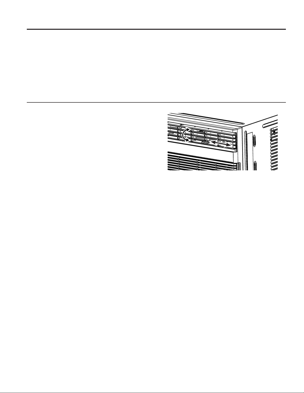
Air Direction
Air directional louvers control air flow direction.
The louvers will allow you to direct the air flow up or down
and left or right throughout the room as needed until the
desired left/right direction is obtained. Pivot horizontal
louvers until the desired up/down direction is obtained.
USING THE AIR CONDITIONER
6 49-5000444 Rev. 0
Page 7

Care and Cleaning
Air filter
To access the filter, grasp the front grille on both sides at
the recess and tilt forward. Remove the filter by lifting up
and out. Note the filter direction when re-installing.
Wash the filter using liquid dishwashing detergent and
warm water. Rinse the filter thoroughly. Gently shake
excess water from the filter.
Energy Saving Note
In order to reach maximum energy saving and comfort, it
is recommended to use a cover to insulate the unit when
the unit is not in use. The recommended cover size for
the unit is 24.4” x 14.8” x 2.2” (W x H x D).
Cabinet
• Be sure to unplug the air conditioner to prevent shock
or fire hazard. The cabinet and front may be dusted
with an oil-free cloth or washed with a cloth dampened
in a solution of warm water and mild liquid dishwashing
detergent. Rinse thoroughly with a damp cloth and wipe
dry.
Be sure the filter is thoroughly dry before replacing. Or,
instead of washing, you may vacuum the filter until clean.
NOTE: Never use hot water over 104°F (40°C) to clean
the air filter. Never attempt to operate the unit without the
air filter.
NOTE: Unplug the unit before installing a cover.
•
Never use harsh cleaners, wax, or polish on the cabinet front.
• Be sure to wring excess water from the cloth before
wiping around the controls. Excess water in or around
the controls may cause damage to the air conditioner.
• Plug in the air conditioner.
CARE AND CLEANING
Outdoor Coils
• The coils on the outdoor side of the air conditioner
should be checked regularly.
• If they are clogged with dirt or soot, they may need to
be professionally cleaned, a service available through
GE Appliances service or other service companies.
How to Insert the Batteries in the Remote Control
1. Remove the battery cover by rotating it to the unlock
position.
2. Insert a new battery, making sure that the (+) and (-) of
the battery are installed correctly, (+) side up.
3. Reattach the cover by rotating it back into the lock
position.
NOTES:
• Use 1 CR2025 (3 VDC) battery. Do not use rechargeable
batteries.
• Remove the battery from the remote control if the
system is not going to be used for an extended period
of time.
Front Grille Removal
The front grille can be removed for a more thorough
cleaning.
To remove:
1. Grasp the sides of the front grille by the recessed
areas on each side and tilt forward.
2. Remove the filter by pulling forward and out.
3. Remove the two Phillips head screws located on the
upper corners of the grille.
4. Push inward on each side of the metal chassis cover
about 5” from the bottom. This will release the tabs on
the grille from the metal chassis cover. Pull the bottom
of the grille slightly forward while lifting the grille
upward.
5. Once the grille is released, gently raise it upward to
release the tabs from the top of the metal chassis cover.
6. To release the multi-pin electrical connector from the
user interface, press both sides and gently pull apart.
Reverse the order to re-install the grille.
49-5000444 Rev. 0 7
Page 8
Installation Instructions
For more help, visit GEAppliances.com
BEFORE YOU BEGIN
Read these instructions completely and carefully.
•
IMPORTANT – Save these
instructions for local inspector’s use.
•
IMPORTANT – Observe all
governing codes and ordinances.
• Note to Installer – Be sure to leave these
instructions with the consumer.
• Note to Consumer – Keep these instructions for
future reference.
• Skill level – Installation of this appliance requires
basic mechanical skills.
• Completion time – Approximately 1 hour
• We recommend that two people install this
product.
INSTALLATION INSTRUCTIONS
• Proper installation is the responsibility of the
installer.
• Product failure due to improper installation is not
covered under the Warranty.
• You MUST use proper installation procedures as
described in these instructions when installing this
air conditioner.
ELECTRICAL REQUIREMENTS
CAUTION
Do not, under any circumstances, cut or remove
the third (ground) prong from the power cord.
Do not change the plug on the power cord of this
air conditioner.
Aluminum house wiring may present special
problems—consult a qualified electrician.
Power cord includes a current interrupter device. A
TEST and RESET button are provided on the plug
case. The device should be tested on a periodic
basis by first pressing the TEST button and then the
RESET button while plugged into the outlet. If the
TEST button does not trip or if the RESET button
will not stay engaged, discontinue use of the air
conditioner and contact a qualified service technician.
IMPORTANT NOTE
For optimal energy efficiency and performance, we
recommend using the RAB24 Wall Sleeve and the
supplied stamped aluminum outdoor grille or the
RAB46B with the RAG13 stamped aluminum outdoor
grille.
For Existing Wall Sleeves
Note that the air conditioner dimensions are: 24” wide,
14” high, and 18” deep (without front). Install air
conditioner according to these Installation Instructions
to achieve the best performance. Save these Installation
Instructions for future reference.
NOTE: Do not use any screws other than those specified
here.
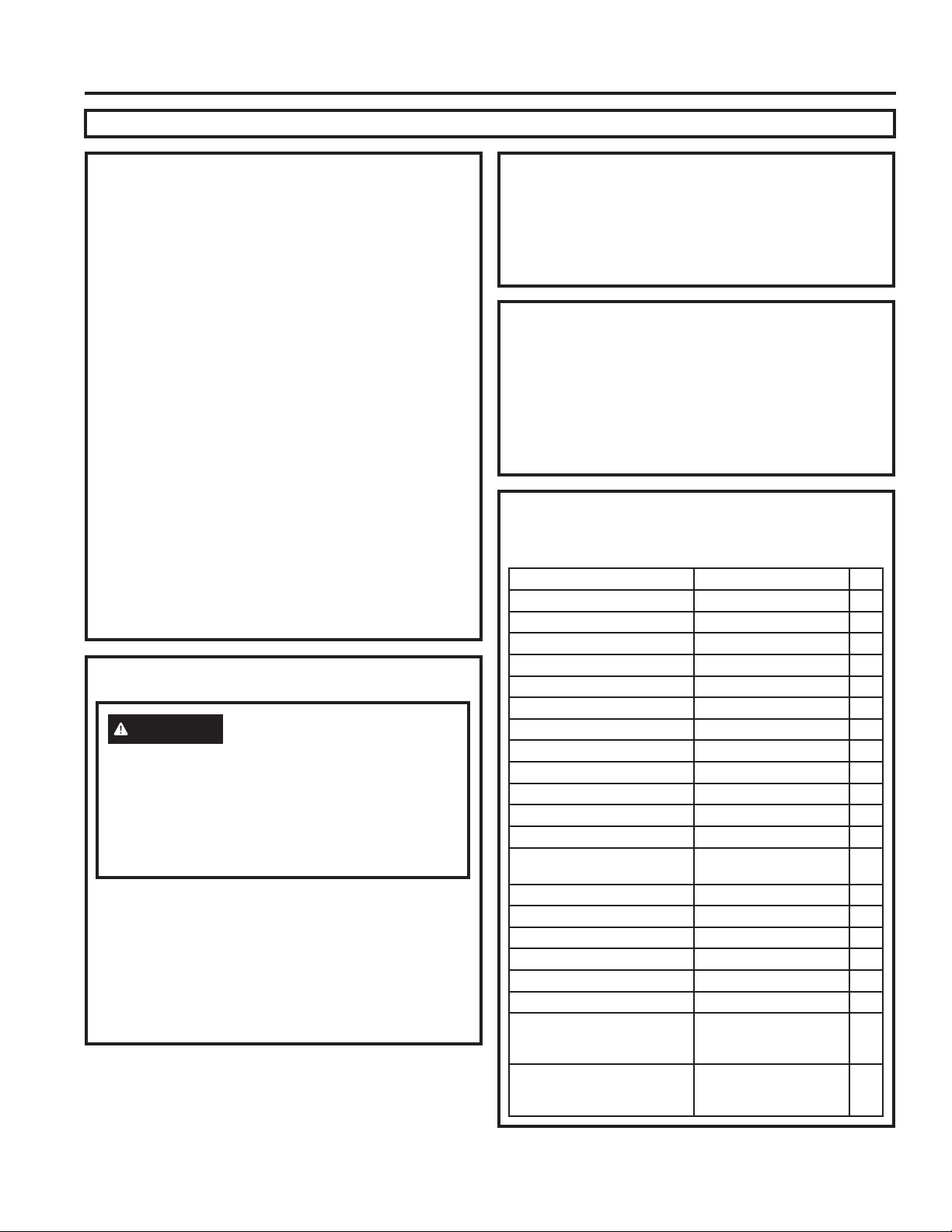
Parts Included
You may not need all parts in the kit. Discard unused
parts.
Name Spec. Qty
Tapered spacer Blocks 17” long 2
Centering/Support Blocks 4-1/2” x 3-1/2” x 1-1/2” 4
Plastic Divider 1/8” x 4-1/2” x 14-1/2” 2
Stuffer Seal 1” x 1-1/2” x 25” 1
Seal 1” x 1-1/2” x 14” 3
Seal 1” x 3/8” x 25” 2
Seal 1” x 3/8” x 14” 3
Seal 1” x 3/4” x 14” 2
Seal 2
Trim Frame (side legs) 2
Trim Frame (top & bottom legs) 2
Ground Wire (green) 1
Toothed Washer for grounding
screw
Grounding Screw 1
Grille (Plastic) 1
Grille (Aluminum) 1
Nuts (Plastic) 4
Screw Washer 4
Screw 4
Security Brackets for a 24” Wall
Sleeve (in a separate packet
with their 4 mounting screws)
Security Brackets for a 26” Wall
Sleeve (in a separate packet
with their 4 mounting screws)
2
2
2
8 49-5000444 Rev. 0
Page 9
Installation Instructions
UNIT
LEVEL
INSTALLATION INSTRUCTIONS
How to Install In Pre-Existing Wall
Sleeve
1. Identify the wall-sleeve brand for your installation,
from the chart below.
Wall Sleeve Dimensions (inches)
Width Height Depth
White-Westinghouse
Frigidaire
Carrier (52F Series)
GE/Hotpoint 26 15-5/8 15-7/8
Whirlpool 25-7/8 16-1/2 17-1/8 or 23
Fedders/Emerson 27 16-3/4 16-3/4 or 19-3/4
Sears/Kenmore
Carrier (51S Series)
Emerson/Fedders 26-3/4 15-3/4 15
Friedrich 27 16-3/4 16-3/4
NOTE: All wall sleeves used to mount the new air
conditioner must be in sound structural condition and
have a rear grille that securely attaches to sleeve, or
rear flange that serves as a stop for the air conditioner.
IMPORTANT: When installation is complete, replacement
unit MUST have a rearward slope as shown.
REAR
2. Remove old air conditioner from wall sleeve and
prepare wall sleeve as follows:
■ Clean interior (do not disturb seals).
■
Wall sleeve must be securely fastened in wall
before installing air conditioner. Drive more nails or
screws through sleeve, into wall, if needed.
■ Repair paint if needed.
3.
If not pre-existing, drill a 1/8” hole to attach the supplied
grounding wire to the left side of the wall sleeve (see
approximate hole location dimensions in the illustration
below). Use the toothed washer and pointed screw to
attach one end of the supplied green striped ground
wire to the inside of the wall sleeve. The toothed
washer must be between the eyelet of the wire and the
wall sleeve. BE CAREFUL TO NOT OVERTIGHTEN
THE SCREW. Pull loose end of ground wire out front
of sleeve, and temporarily bend it down and around
lower edge of sleeve. This ground wire will later be
attached to frame of air conditioner once it is installed.
25-1/2 15-1/4 16, 17-1/2 or 22
25-3/4 16-7/8 18-5/8
3
to
Wall Sleeve
FRONT
3
Max.
1/8
Hole
How to Install In Pre-Existing Wall
Sleeve (continued)
4. Prepare the wall sleeve for installation of the new
unit per the following brand instructions.
1 Emerson 15” Deep
2 Fedders 19-3/4” Deep
3 Fedders or Friedrich 16-3/4” Deep
4 GE/Hotpoint 16-7/8” Deep
5 Sears or Carrier (51S Series) 18-5/8” Deep
6 Whirlpool 17-1/8” Deep
7 Whirlpool 23” Deep
8 White-Westinghouse/
Frigidaire/Carrier (52F Series)
9 White-Westinghouse/Frigidaire 22” Deep
16” + 17-1/2” Deep
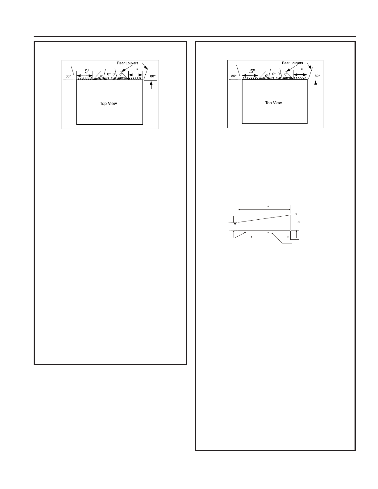
5. Identify your wall sleeve type and follow the
instructions for that type in the following pages.
IMPORTANT - BEFORE YOU BEGIN
■ This unit’s performance characteristics result from
having two rear air intakes.
■ It is very important that these instructions are followed
so the unit can operate at maximum efficiency.
■ If this is an existing sleeve and there is an existing
rear grille, it may need to be replaced by one that has
been shipped with the unit in the accessory kit. If the
new rear grille is too small for the rear sleeve opening,
use the black plastic grille. Insure it is secured in place
using the included screws, washers and grommets.
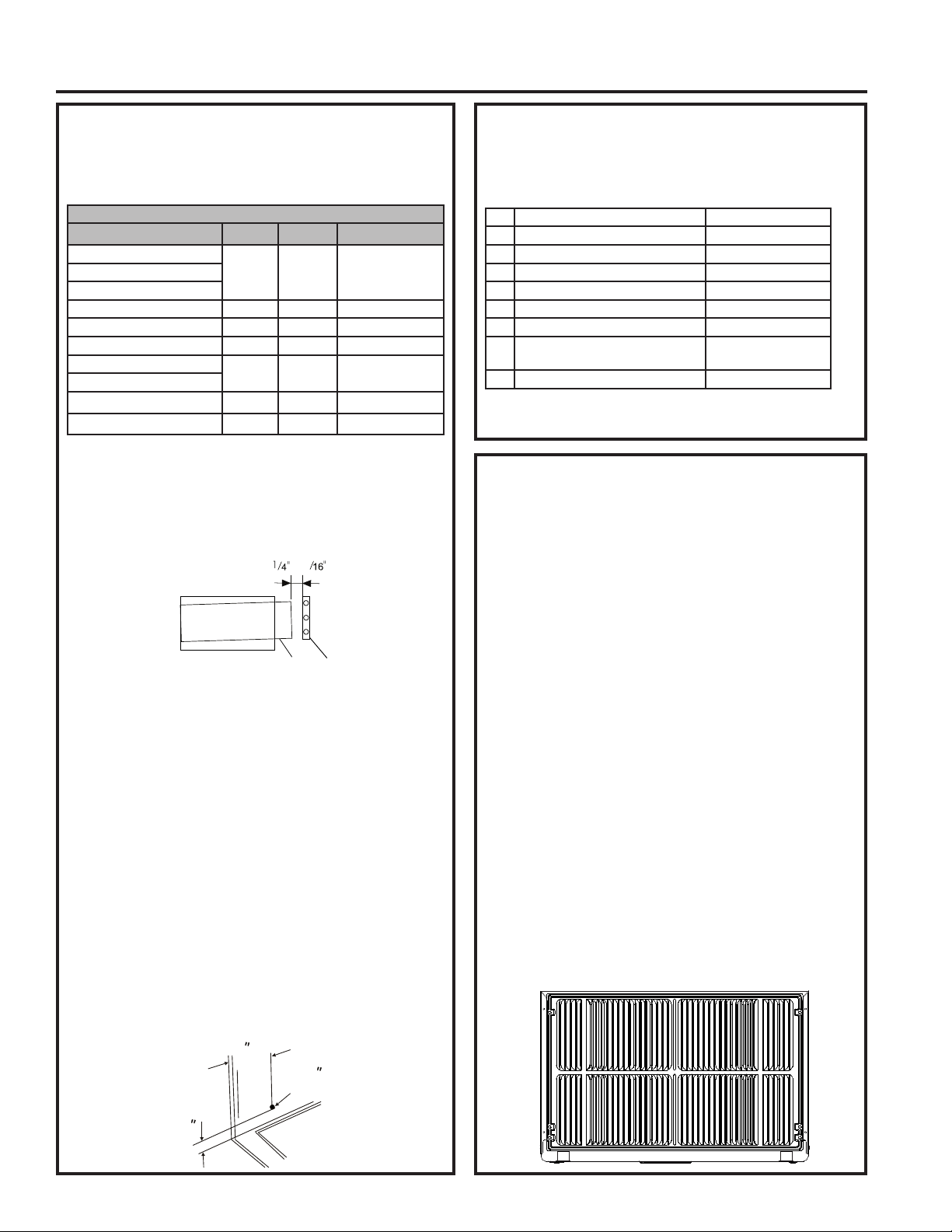
FOR INCREASED EFFICIENCY, UTILIZE THE
PROVIDED LOUVERED REAR PANEL
Installation of new grille provided with unit.
1. Remove the existing grille. (Exception: GE 26”.)
2. Place the grille, included with the new air
conditioner, towards the rear of the sleeve.
3. Mark through the hole positions.
4. Drill through the sleeves flanges with a 1/8” drill bit.
5. Attach the new grille with self-threading screws
and washers.
6. It is VERY IMPORTANT that the grille is placed
exactly as shown below.
7. Most decorative exterior grilles may be left in place as
long as the proper interior air direction grille is installed.
1
49-5000444 Rev. 0 9
Page 10
Installation Instructions
Emerson (15” Deep)
4
838
3
1. Remove existing rear grille as shown on page 9 of
this manual and replace with provided louvered rear
panel.
NOTE: You may need to drill holes in flange of existing
sleeve to match new rear grille.
2. Attach (1) 1” x 3/8” x 25” long seal in the center at
the top of the sleeve. Remove the backing paper
and press into position.
3. Attach the (2) 1” x 3/8” x 14” long seals to the left
INSTALLATION INSTRUCTIONS
and right sides of the sleeve.
4. Cut (2) 1” x 3/8” x 25” seals to 14” long and attach
them to the vertical sections of the rear grille.
5. Attach (2) 4-1/2” x 3-1/2” x 1-1/2” centering/support
blocks, one on each side wall. Place in center of
side wall with the tapered end facing the opening.
6. Gently slide unit into sleeve.
7. Before sliding all-the-way back, remove the second
screw from front on the left side of unit.
8. Remove the plastic washer from the screw.
9. Screw and attach the other end of the ground wire
to the unit. Make sure that the toothed washer is
against the cabinet.
10. Slide the unit completely to the rear to ensure a
good seal, making sure the ground wire does not
become tangled.
11. If you have difficulty with mounting the grill to the
sleeve, follow the instructions for direct mounting on
page 15.
12. Seal and frame the unit as described on page 16.
4
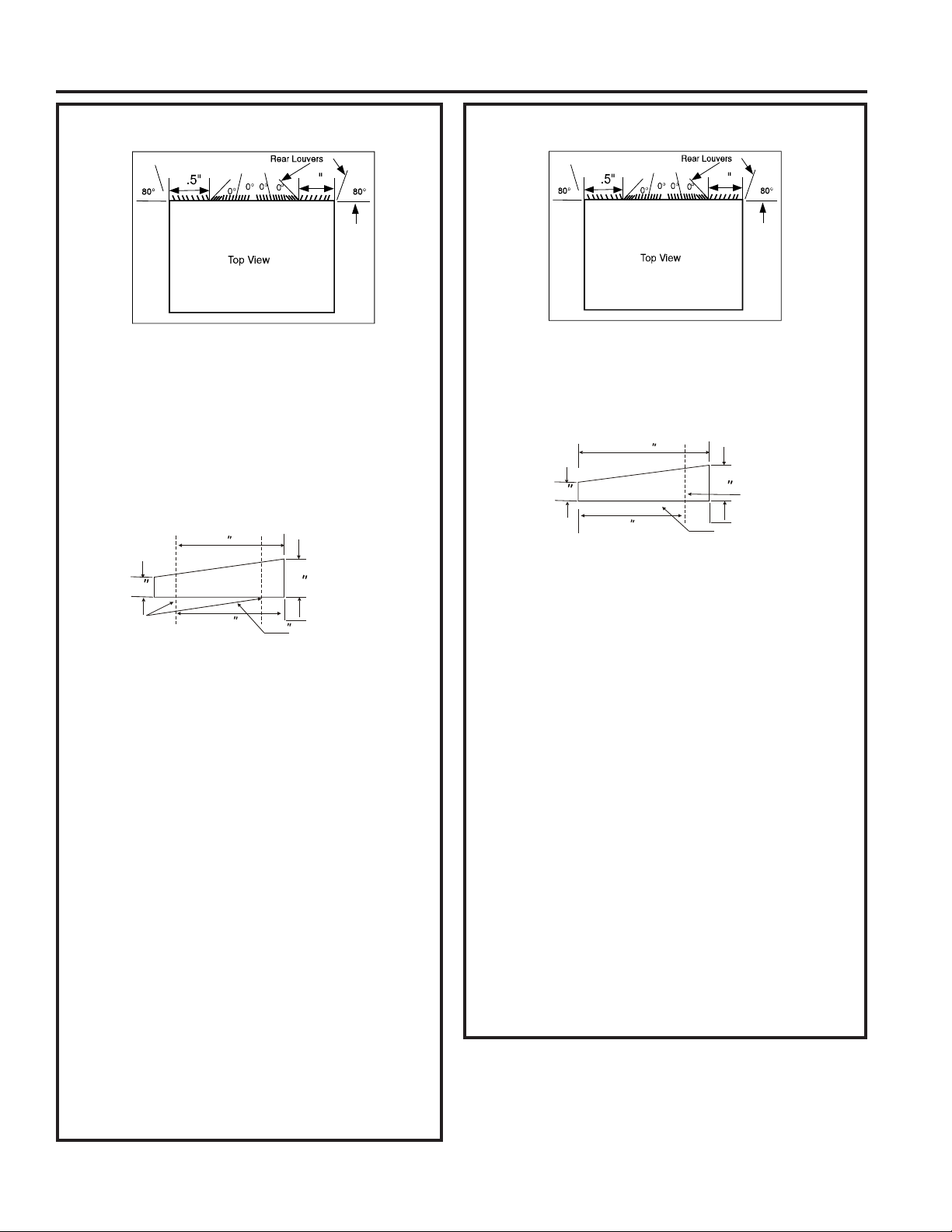
Fedders (19-3/4” Deep)
4
838
3
1. Remove existing rear grille as shown on page 9 of
this manual and replace with provided louvered rear
panel.
NOTE: You may need to drill holes in flange of existing
sleeve to match new rear grille.
2 Attach (2) 4-1/2” x 3-1/2” x 1-1/2” centering/support
blocks, one on each side wall. Place in center of
side wall with the tapered end facing the opening.
3. Cut (2) 17” tapered spacer blocks as shown below
into two pieces.
17
/
4
Tapered Spacer Block
4
3
Cut Here
4. The 4” section is placed in front of the rib on base
with the tapered end facing the back of the sleeve.
The remaining portion will be placed behind the rib
again sloping toward
the rear of the sleeve. This helps induce a rearward
slope on the unit.
5. Attach (1) 1” x 3/8” x 25” long seal in the center at
the top of the sleeve. Remove the backing paper
and press into position.
6. Attach (2) 1” x 3/8” x 14” seals to the left and right
sides of the sleeve.
7. Cut (2) 1” x 3/8” x 25” seals to 14” long and attach
them to the vertical sections of the rear grille.
8. Gently slide unit into sleeve.
9. Before sliding all-the-way back, remove the second
screw from front on left side of unit.
10. Remove the plastic washer from the screw.
11. Screw and attach the other end of the ground wire
to the unit. Make sure that the toothed washer is
against the cabinet.
12. Slide the unit completely to the rear to ensure a
good seal, making sure the ground wire does not
become tangled.
13. If you have difficulty with mounting the grill to the
sleeve, follow the instructions for direct mounting
on page 15.
14. Seal and frame the unit as described on page 16.
4
1
Protection Paper
Backing
10 49-5000444 Rev. 0
Page 11
Installation Instructions
4
4
3
838
3
/
4
17
Tapered Spacer Block
1
Protection Paper
Backing
Cut Here
13
INSTALLATION INSTRUCTIONS
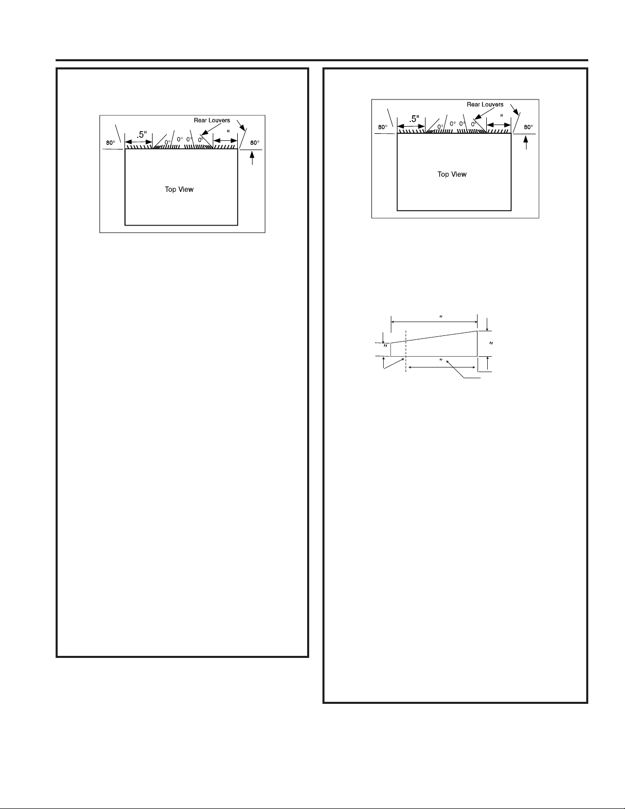
Fedders or Friedrich (16-3/4” Deep)
1
2-1/2
Protection Paper
Backing
4
4
838
3
1. Remove existing rear grille as shown on page 9 of
this manual and replace with provided louvered rear
panel.
NOTE: You may need to drill holes in flange of existing
sleeve to match new rear grille.
2. Attach (2) 4-1/2” x 3-1/2” x 1-1/2” centering/support
blocks, one on each side wall. Place in center of side
wall with the tapered end facing the opening.
3. Cut (2) 17” tapered spacer blocks as shown below
into three pieces.
17
/
4
Tapered Spacer Block
12-1/2
3
Cut Here
4. The 2-1/2” section is placed in front of the rib on base
with the tapered end facing the back of the sleeve. Cut
the remaining portion to 12-1/2” and placed behind the
rib again sloping toward the rear of the sleeve. This
helps induce a rearward slope on the unit.
5. Attach (1) 1” x 3/8” x 25” long seal in the center at
the top of the sleeve. Remove the backing paper
and press into position.
6. Attach (2) 1” x 3/8” x 14” seals to the left and right
sides of the sleeve.
7. Cut (2) 1” x 3/8” x 25” seals to 14” long and attach
them to the vertical sections of the rear grille.
8. Gently slide unit into sleeve.
9. Before sliding all-the-way back, remove the second
screw from front on left side of unit.
10. Remove the plastic washer from the screw.
11. Screw and attach the other end of the ground wire
to the unit. Make sure that the toothed washer is
against the cabinet.
12. Slide the unit completely to the rear to ensure a
good seal, making sure the ground wire does not
become tangled.
13. If you have difficulty with mounting the grill to the
sleeve, follow the instructions for direct mounting
on page 15.
14. Seal and frame the unit as described on page 16.
GE/Hotpoint (16-7/8” Deep)
1. Retain existing rear grille.
2. Using needle nose pliers, change the outdoor grille
directional louvers per the illustration above.
3. Cut (2) 17” tapered spacer blocks as shown below
into two pieces.
4. Install 13” section with the tapered end 1/2” from the
back of the sleeve. This helps induce a rearward
slope on the unit.
5. Attach (1) 1” x 3/8” x 25” long seal in the center at
the top of the sleeve. Remove the backing paper
and press into position.
6. Attach (2) 1” x 3/8” x 14” seals to the left and right
sides of the sleeve.
7. Cut (2) 1” x 3/8” x 25” seals to 14” long and attach
them to the vertical sections of the rear grille.
8. Center unit and gently slide unit into sleeve.
9. Before sliding all-the-way back, remove the second
screw from front on left side of unit.
10. Remove the plastic washer from the screw.
11. Screw and attach the other end of the ground wire
to the unit. Make sure that the toothed washer is
against the cabinet.
12. Slide the unit completely to the rear to ensure a
good seal, making sure the ground wire does not
become tangled.
13. If you have difficulty with mounting the grill to the
sleeve, follow the instructions for direct mounting
on page 15.
14. Seal and frame the unit as described on page 16.
49-5000444 Rev. 0 11
Page 12
Installation Instructions
Sears or Carrier 51S Series
(18-5/8” Deep)
4
838
3
1. Remove existing rear grille as shown on page 9 of
this manual and replace with provided louvered rear
panel.
NOTE: You may need to drill holes in flange of
existing sleeve to match new rear grille.
2. Install (2) tapered spacer blocks to the floor of the
sleeve. This helps induce a rearward slope on the
INSTALLATION INSTRUCTIONS
unit.
3. Install with the tapered end 1/2” from the back of the
sleeve. This helps induce a rearward slope on the
unit.
4. Attach (1) 1” x 3/8” x 25” long seal in the center at
the top of the sleeve. Remove the backing paper
and press into position.
5. Attach (2) 1” x 3/8” x 14” seals to the left and right
sides of the sleeve.
6. Cut (2) 1” x 3/8” x 25” seals to 14” long and attach
them to the vertical sections of the rear grille.
7. Center unit and gently slide unit into sleeve.
8. Before sliding all-the-way back, remove the second
screw from front on left side of unit.
9. Remove the plastic washer from the screw.
10. Screw and attach the other end of the ground wire
to the unit. Make sure that the toothed washer is
against the cabinet.
11. Slide the unit completely to the rear to ensure a
good seal, making sure the ground wire does not
become tangled.
12. If you have difficulty with mounting the grill to the
sleeve, follow the instructions for direct mounting on
page 15.
13. Seal and frame the unit as described on page 16.
4
Whirlpool (17-1/8” Deep)
4
838
3
1. Remove existing rear grille as shown on page 9 of this
manual and replace with provided louvered rear panel.
NOTE: You may need to drill holes in flange of existing
sleeve to match new rear grille.
2. Cut (2) 17” tapered spacer blocks as shown below
into two pieces.
17
3
Tapered Spacer Block
/
4
Cut Here
13
3. Install 13” section to the floor of the sleeve. This
helps induce a rearward slope on the unit.
4. Attach (1) 1” x 3/8” x 25” long seal in the center at
the top of the sleeve. Remove the backing paper
and press into position.
5. Attach (2) 1” x 3/8” x 14” seals to the left and right
sides of the sleeve.
6. Cut (2) 1” x 3/8” x 25” seals to 14” long and attach
them to the vertical sections of the rear grille.
7. Center unit and gently slide unit into sleeve.
8. Before sliding all-the-way back, remove the second
screw from front on left side of unit.
9. Remove the plastic washer from the screw.
10. Screw and attach the other end of the ground wire
to the unit. Make sure that the toothed washer is
against the cabinet.
11. Slide the unit completely to the rear to ensure a
good seal, making sure the ground wire does not
become tangled.
12. If you have difficulty with mounting the grill to the
sleeve, follow the instructions for direct mounting
on page 15.
13. Seal and frame the unit as described on page 16.
4
1
Protection Paper
Backing
12 49-5000444 Rev. 0
Page 13

Installation Instructions
INSTALLATION INSTRUCTIONS
Whirlpool (23” Deep)
4
1. Remove existing rear grille as shown on page 9 of this
manual and replace with provided louvered rear panel.
NOTE: You may need to drill holes in flange of existing
sleeve to match new rear grille.
Because of the increased unit depth, first try dry
fitting using the method described below:
2. Place (2) 1” x 1-1/2” x 14” seals against each side.
3. Gently slide unit in and check if amount extending
from the sleeve is sufficient once the trim frame is
attached.
4. If position is correct, remove unit and proceed to the
next step. If not, go to step 9.
5. Attach (1) 1” x 1-1/2” x 25” long seal in the center
at the top of the sleeve. Remove the backing paper
and press into position.
6. Attach (2) 1” x 1-1/2” x 14” seals to the left and right
sides of the sleeve.
7. Cut (2) 1” x 3/8” x 25” seals to 14” long and attach
them to the vertical sections of the grille.
8. Attach the tapered spacer blocks to the floor of the
sleeve. Now go to step 15.
Use these next steps if the unit requires extra
extension into the room:
9. Attach 1” x 3/4” x 14” long seal over the solid vertical
portion of the rear grille.
10. Attach (4) 4-1/2” x 3-1/2” x 1-1/2” foam blocks with
the slot overlapping the seal above.
11. Install the divider into the slots of the foam blocks.
You may need to trim the length to size.
12. Repeat steps 9-11 for the other vertical portion of
the grille.
13. Attach (2) 1” x 1-1/2” x 14” seals along the sides of
the sleeve again making sure all seals are flush.
14. Cut the 1” x 1-1/2” x 25” seal to fit the top of the
sleeve. The pieces must be fitted flush to the edge
of the divider.
15. Center unit and gently slide unit into sleeve.
16. Before sliding all-the-way back, remove the first
screw from front on left side of unit.
838
3
4
Whirlpool (23” Deep) continued
17. Remove the plastic washer from the screw.
18. Screw and attach the other end of the ground
wire to the unit. Make sure that the toothed
washer is against the cabinet.
19. Slide the unit completely to the rear to ensure a
good seal, making sure the ground wire does not
become tangled.
20. If you have difficulty with mounting the grill to the
sleeve, follow the instructions for direct mounting
on page 15.
21. Seal and frame the unit as described on page 16.
49-5000444 Rev. 0 13
Page 14

Installation Instructions
White-Westinghouse/Frigidaire/Carrier
52F Series (16” + 17-1/2” Deep)
4
838
3
1. Remove existing rear grille as shown on page 9 of
this manual and replace with provided louvered rear
panel.
NOTE: You may need to drill holes in flange of
existing sleeve to match new rear grille.
2. Attach (1) 1” x 3/8” x 25” long seal in the center at
the top of the sleeve. Remove the backing paper
and press into position.
3. Attach (2) 1” x 3/8” x 14” seals to the left and right
INSTALLATION INSTRUCTIONS
sides of the sleeve.
4. Attach (2) 1” x 3/4” x 14” long seals vertically 4.5”
from the left side of the sleeve and 4” from the
right side of the sleeve.
5. Center unit and gently slide unit into sleeve.
6. Before sliding all-the-way back, remove the
second screw from front on left side of unit.
7. Remove the plastic washer from the screw.
8. Screw and attach the other end of the ground
wire to the unit. Make sure that the toothed
washer is against the cabinet.
9. Slide the unit completely to the rear to ensure
a good seal, making sure the ground wire does
not become tangled.
10. If you have difficulty with mounting the grill to the
sleeve, follow the instructions for direct mounting
on page 15.
11. Seal and frame the unit as described on page 16.
4
White-Westinghouse or Frigidaire
(22” Deep)
4
1. Remove existing rear grille as shown on page 9 of this
838
3
manual and replace with provided louvered rear panel.
NOTE: You may need to drill holes in flange of existing
sleeve to match new rear grille.
Because of the increased unit depth, first try dry
fitting using the method described below:
2. Place (2) 1” x 1-1/2” x 14” seals against each side.
3. Gently slide unit in and check if amount extending from
the sleeve is sufficient once the trim frame is attached.
4. If position is correct, remove unit and proceed to the
next step. If not, go to step 8.
5. Attach (1) 1” x 1-1/2” x 15” long seal to the left side
and right side of the sleeve.
6. Cut (1) 1” x 1-1/2” x 25” seal to 14” long and attach
them vertically to the rear grill 4.5” from the left side of
the sleeve and 4” from the right side of the sleeve.
7. Attach (1) 1” x 1-1/2” x 25” long seal in the center at
the top of the sleeve. Remove the backing paper and
press into position. Proceed to step 14.
Use these next steps if the unit requires extra
extension into the room.
8. Attach 1” x 3/4” x 14” long seal over the solid vertical
portion of the rear grille.
9. Attach (4) 4-1/2” x 3-1/2” x 1-1/2” foam blocks with the
slot overlapping the seal above.
10. Install the divider into the slots of the foam blocks.
You may need to trim the length to size.
11. Repeat steps 8-10 for the other vertical shown
portion of the grille.
12. Attach (2) 1” x 1-1/2” x 14” seals along the sides of
the sleeve again making sure all seals are flush.
13. Cut the 1” x 1-1/2” x 25” seal to fit the top of the
sleeve. The pieces must be fitted flush to the edge of
the divider.
14. Center unit and gently slide unit into sleeve.
15. Before sliding all-the-way back, remove the first
screw from the front on left side of the unit.
16. Remove the plastic washer from the screw.
17. Screw and attach the other end of the ground wire
to the unit. Make sure that the toothed washer is
against the cabinet.
18. Slide the unit completely to the rear to ensure a good seal,
making sure the ground wire does not become tangled.
19. If you have difficulty with mounting the grill to the
sleeve, follow the instructions for direct mounting
on page 15.
20. Seal and frame the unit as described on page 16.
4
14 49-5000444 Rev. 0
Page 15
Installation Instructions
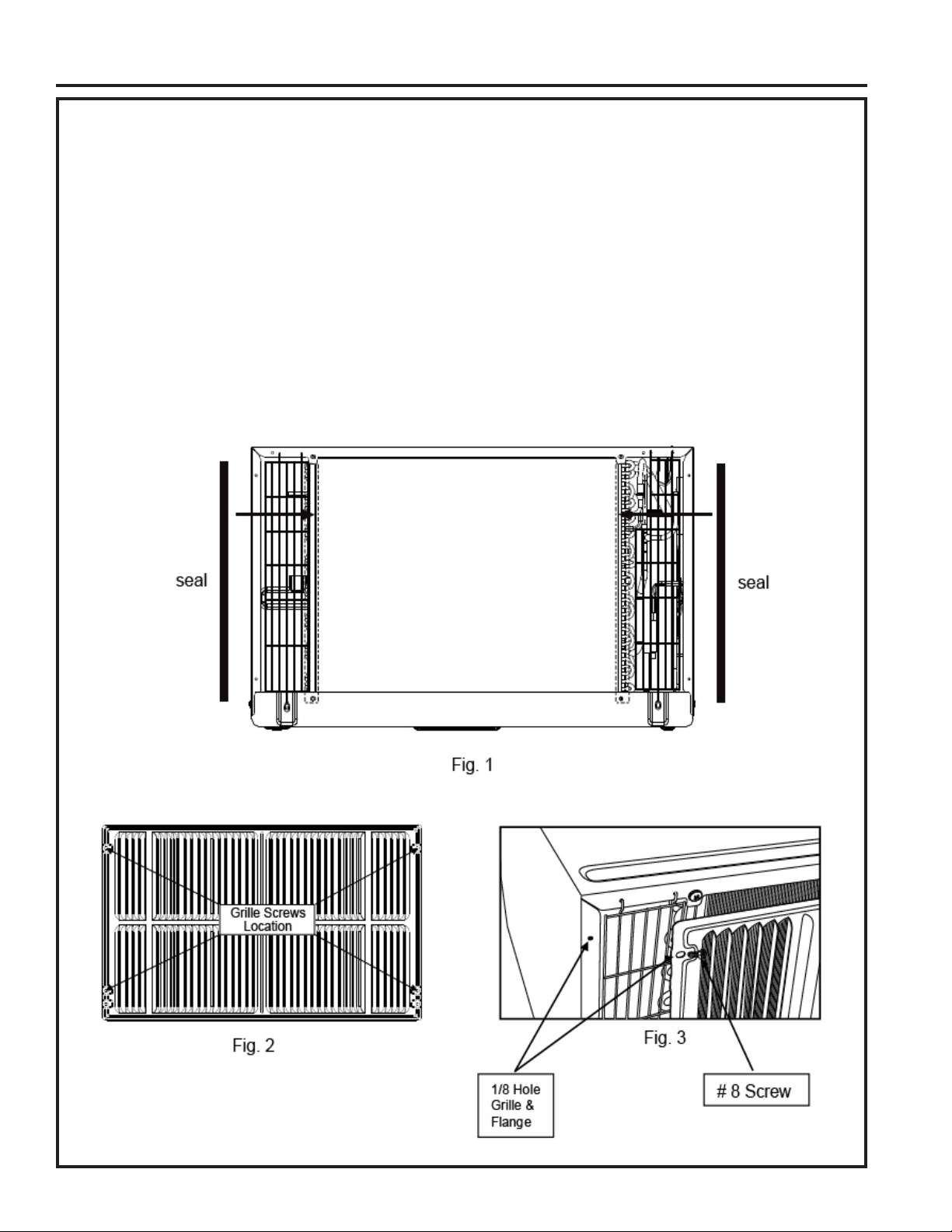
Direct Unit Mounting:
The previous directions are the preferable way to mount the new rear grille. The units performance is slightly
better and the possibility of drafts is reduced. As a last resort, direct mounting of the grille to the unit can be
considered.
NOTE: The grille must be installed prior to inserting the unit into the sleeve.
1. Attach the 2 seal pieces (1” x 3/8” x 14”) as shown in the illustration.
2. Position the grille over the rear of the unit making sure that:
a. The double set of screw holes are at the bottom.
b. The fins of the grille are pointed away from the unit.
3. Align the top of the grille with the top of the unit. The overhang on each side should be equal.
4. If the unit has not been pre-drilled (some models), carefully drill (4) 1/8” holes through the grille and into the
side flange of the unit approximately 1-1/2” to 2” from the top and bottom as shown.
5. Install 4 #8 self-tapping screws to affix the grille to the unit.
6. Insert the unit into the sleeve.
INSTALLATION INSTRUCTIONS
49-5000444 Rev. 0 15
Page 16
Installation Instructions
Assemble Trim
Hook inside
sleeve edge
and secure
to unit
Hook inside
sleeve edge
and secure
to unit
Trim Kit Installation Instructions
■
Install the 1” x 1-1/2” x 84” long stuffer seal
between the wall sleeve and the unit. A flat-bladed
screwdriver or putty knife is recommended.
■ Measure the height and width of the installed wall
sleeve and choose the appropriate trim kit that
matches those dimensions.
■
Assemble the trim frame by inserting the top and
bottom pieces into side pieces and snapping into
place.
■
Pull the cord through the trim frame and slide the
trim over the unit until flush with the wall or wall
sleeve.
INSTALLATION INSTRUCTIONS
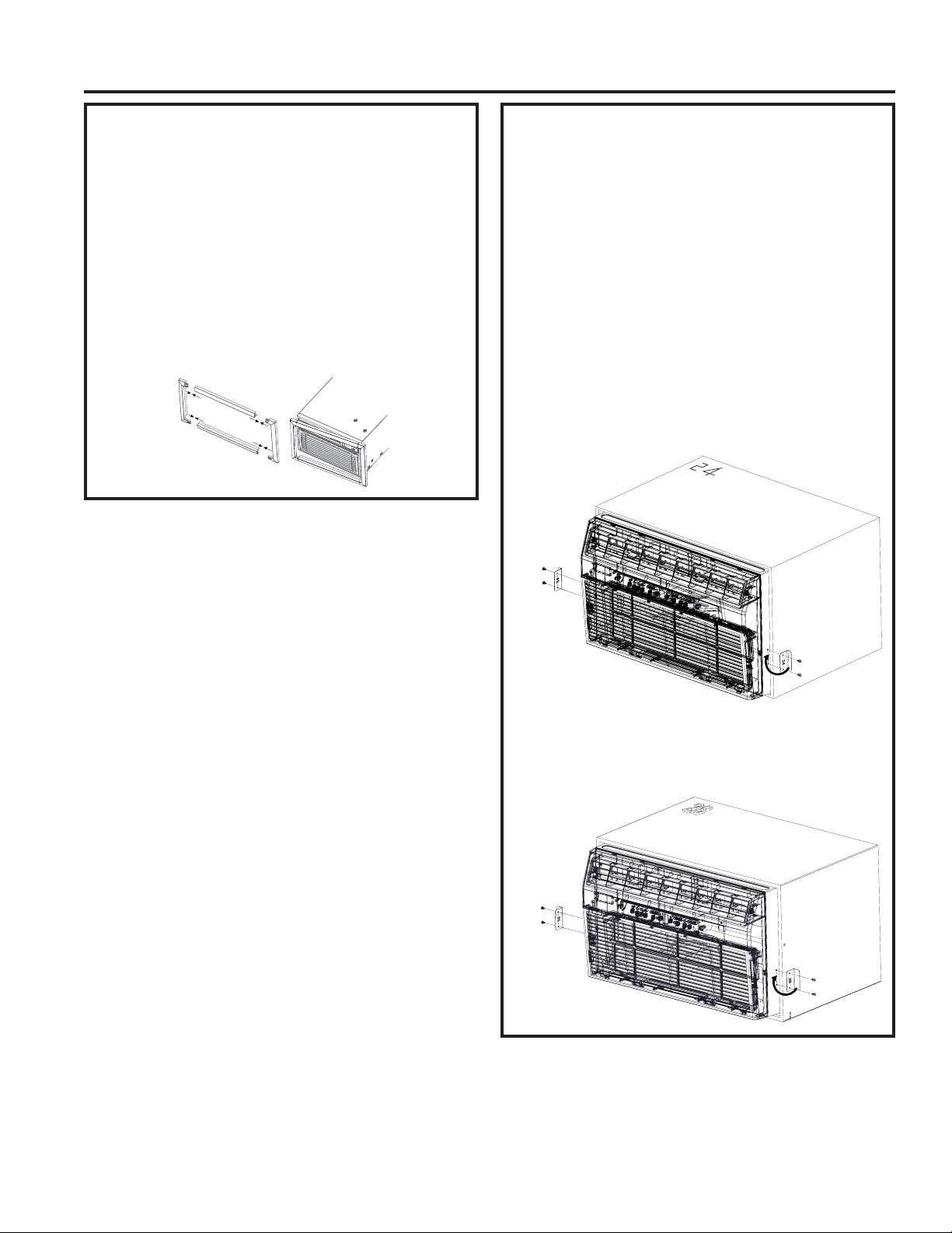
Security Brackets Installation
(It is important to install these brackets
to prevent the chassis from being
pushed into the room from the outside.)
■ Measure the width of the installed wall sleeve and
choose the appropriate security bracket (24” or 26”)
designed for that sleeve.
■
The brackets must be installed so the flanges are
hooked behind the inside flanges of the wall sleeve.
Using the screws provided, attach the brackets on
the sides of the chassis.
For 24” sleeves, pull the unit out slightly, hook the
short flange of the 24” bracket behind the sleeve
inside edge and secure to the unit with the two
screws provided. Repeat on the opposite side.
Push the unit all the way back into the case.
Hook inside
sleeve edge
and secure
to unit
For 26” sleeves, hook the short flange of the 26”
bracket behind the sleeve inside edge and secure
to the unit with the the two screws provided.
Repeat on the opposite side.
Hook inside
sleeve edge
and secure
to unit
16 49-5000444 Rev. 0
Page 17

Troubleshooting Tips... Before you call for service
Problem Solution
Air conditioner does
not start
Air from the unit does
not feel cold enough
Air conditioner cooling,
but room is too warm.
Ice is forming on
cooling coil behind
decorative front.
Air conditioner turns on
and off rapidly
Noise when unit is
cooling
Water dripping INSIDE
when unit is cooling
Water dripping
OUTSIDE when unit is
cooling
Room too cold Set temperature to low. Increase set temperature.
Error code “AS” in the
display
Error code “HS” in the
display
Error code “•” in the
display
Wall plug disconnected. Push plug firmly into wall outlet.
House fuse blown or circuit breaker tripped. Replace fuse with time delay type
or reset circuit breaker.
Plug current device tripped. Press the RESET button.
Power is OFF. Turn power ON.
Room temperature below 62°F (17°C). Cooling may not occur until room
temperature rises above 62°F (17°C).
Temperature sensor behind air filter may be touching cold coil. Keep it from the
cold coil.
Set to a lower temperature.
Compressor stopped when changing modes. Wait for 3 minutes after set to the
COOL mode.
Outdoor temperature below 64°F (18°C). To defrost the coil, set FAN ONLY mode.
Air filter may be dirty. Clean the filter. Refer to Care and Cleaning section. To
defrost, set to FAN ONLY mode.
Thermostat set to cold for night-time cooling. To defrost the coil, set to FAN
ONLY mode. Then, set temperature to a higher setting.
Dirty air filter, or the air is restricted. Clean the air filter. Refer to Care and
Cleaning section.
Temperature is set too high. Set the temperature to a lower setting.
Air directional louvers positioned improperly. Position louvers for better air
distribution.
Front of unit is blocked by drapes, blinds, furniture, etc, which restricts air
distribution. Clear blockage in front of unit.
Doors, windows, registers, etc, may be open. Close doors, windows, registers.
Unit recently turned on in hot room. Allow additional time to remove “stored
heat” from walls, ceiling, floor, and furniture.
Dirty air filter, the air is restricted. Clean air filter.
Outside temperature extremely hot. Set FAN speed to a higher setting to cool
outdoor cooling coil.
Air movement sound. This is normal. If too loud, set to a slower FAN setting.
Improper installation. Refer to installation instructions or check with installer.
Improper installation. Tilt air conditioner slightly to the outside to allow water
drainage. Refer to installation instructions, and check with installer.
Unit removing large quantity of moisture from humid room. This is normal
during excessively humid days.
Room temperature sensor error. Unplug the unit and plug it back in. If error
repeats, call for service. NOTE: In Fan only mode, it will display “LO” or “HI”.
Electric heating sensor error. Unplug the unit and plug it back in. If error
repeats, call for service.
Evaporator temperature sensor error. Unplug the unit and plug it back in. If
error repeats, call for service.
TROUBLESHOOTING TIPS
49-5000444 Rev. 0 17
Page 18

Notes
NOTES
18 49-5000444 Rev. 0
Page 19

GE Appliances Air Conditioner Limited Warranty
All warranty service must be provided by our Factory Service Centers, or an authorized Customer Care® technician.
To schedule service, visit us on-line at GEAppliances.com/service, or call 800.GE.CARES (800.432.2737). Have
serial number and model number available when calling for service.
For The Period Of: GE Appliances Will Replace:
Two Years
From the date of the
original purchase
What GE Appliances Will Not Cover:
Any part of the air conditioner which fails due to a defect in materials or workmanship.
During this limited two-year warranty, GE Appliances will also provide, free of charge, all
labor and related service to replace the defective part.
LIMITED WARRANTY
■ Service trips to your home to teach you how to use
the product.
■ Improper installation, delivery or maintenance. If you
have an installation problem, or if the air conditioner
is of improper cooling capacity for the intended use,
contact your dealer or installer. You are responsible
for providing adequate electrical connecting facilities.
■ Failure of the product resulting from modifications
to the product or due to unreasonable use including
failure to provide reasonable and necessary
maintenance.
■ In commercial locations, labor necessary to move the
unit to a location where it is accessible for service by
an individual technician.
EXCLUSION OF IMPLIED WARRANTIES—Your sole and exclusive remedy is product repair as provided in this
Limited Warranty. Any implied warranties, including the implied warranties of merchantability or fitness for a
particular purpose, are limited to two years or the shortest period allowed by law.
This limited warranty is extended to the original purchaser and any succeeding owner for products purchased
for home use within the USA. If the product is located in an area where service by a GE Appliances Authorized
Servicer is not available, you may be responsible for a trip charge or you may be required to bring the product to an
Authorized GE Service location for service. In Alaska, the limited warranty excludes the cost of shipping or service
calls to your home.
■ Replacement of house fuses or resetting of circuit
breakers.
■ Failure due to corrosion on models not corrosionprotected.
■ Damage to the product caused by improper power
supply voltage, accident, fire, floods or acts of God.
■ Incidental or consequential damage caused by
possible defects with this air conditioner.
■ Damage caused after delivery.
Staple your receipt here. Proof of the original purchase date
is needed to obtain service under the warranty.
Some states do not allow the exclusion or limitation of incidental or consequential damages. This limited warranty
gives you specific legal rights, and you may also have other rights which vary from state to state. To know what your
legal rights are, consult your local or state consumer affairs office or your state’s Attorney General.
Warrantor: GE Appliances, a Haier company
Louisville, KY 40225
49-5000444 Rev. 0 19
Page 20

Consumer Support
GE Appliances Website
Have a question or need assistance with your appliance? Try the GE Appliances Website 24 hours a day, any day
of the year! You can also shop for more great GE Appliances products and take advantage of all our on-line support
services designed for your convenience. In the US: GEAppliances.com
Register Your Appliance
Register your new appliance on-line at your convenience! Timely product registration will allow for enhanced
communication and prompt service under the terms of your warranty, should the need arise. You may also mail in
the pre-printed registration card included in the packing material. In the US: GEAppliances.com/register
Schedule Service
Expert GE Appliances repair service is only one step away from your door. Get on-line and schedule your service at
your convenience any day of the year. In the US: GEAppliances.com/service or call 800.432.2737 during normal
CONSUMER SUPPORT
business hours.
Extended Warranties
Purchase a GE Appliances extended warranty and learn about special discounts that are available while your
warranty is still in effect. You can purchase it on-line anytime. GE Appliances Services will still be there after your
warranty expires. In the US: GEAppliances.com/extended-warranty or call 800.626.2224 during normal
business hours.
Parts and Accessories
Individuals qualified to service their own appliances can have parts or accessories sent directly to their homes
(VISA, MasterCard and Discover cards are accepted). Order on-line today 24 hours every day.
In the US: GEApplianceparts.com or by phone at 877.959.8688 during normal business hours.
Instructions contained in this manual cover procedures to be performed by any user. Other servicing
generally should be referred to qualified service personnel. Caution must be exercised, since improper
servicing may cause unsafe operation.
Contact Us
If you are not satisfied with the service you receive from GE Appliances, contact us on our Website with all the
details including your phone number, or write to:
In the US: General Manager, Customer Relations | GE Appliances, Appliance Park | Louisville, KY 40225
GEAppliances.com/contact
Printed in China
20 49-5000444 Rev. 0
Page 21

INFORMATION DE SÉCURITÉ ...3
UTILISANT LE CLIMATISEUR ..4
ENTRETIEN ET NETTOYAGE ....7
INSTRUCTIONS
D’INSTALLATION
...............8
CONSEILS DE DÉPANNAGE ....18
SOUTIEN AU CONSOMMATEUR
Garantie limitée ......................19
Soutien au consommateur ............ 20
MANUEL D’UTILISATION
ET INSTRUCTIONS
D’INSTALLATION
Rafraîchissement uniquement
AKCQ08A
AKCQ10A
AKCQ10D
AKCQ12A
AKCQ12D
AKCQ14D
Réchauffement/Rafraîchessment
AKEQ10D
AKEQ12D
AKEQ14D
Modèles 24” à Travers le mur
Le climatiseur
Transcrivez les numéros de modèle
et de série ici :
# de modèle _____________
# de série _______________
Vous trouverez l’étiquette
signalétique sur le côté du
climatiseur.
GE est une marque déposée de General Electric Company. Fabriqué sous licence de marque.
49-5000444 Rev. 0 01-20 GEA
Page 22

NOUS VOUS REMERCIONS D’ACCUEILLIR GE APPLIANCES CHEZ VOUS
Que vous ayez grandi avec GE Appliances ou qu’il s’agisse de votre première acquisition, nous
sommes heureux de vous accueillir dans notre famille.
Nous sommes fiers du savoir-faire, de l’innovation et de l’esthétique qui composent chaque appareil
GE Appliances, et nous pensons que vous le serez aussi. Dans cette optique, nous vous rappelons
que l’enregistrement de votre électroménager vous assure la communication de renseignements
importants sur le produit et la garantie lorsque vous en avez besoin.
Enregistrez votre électroménager GE en ligne dès maintenant. Des sites Web et des numéros de
téléphone utiles figurent dans la section Soutien au consommateur de ce manuel d’utilisation.
2 49-5000444 Rev. 0
Page 23

INFORMATION DE SÉCURITÉ IMPORTANTES
AVERTISSEMENT
AVERTISSEMENT
LISEZ TOUTES LES DIRECTIVES AVANT D'UTILISER L'APPAREIL
Pour votre sécurité, vous devez suivre les instructions de ce manuel pour
réduire les risques d’incendie, d’explosion, de choc électrique, de dommage à
la propriété, de blessure ou de décès.
■ N’utilisez cet appareil que pour son usage prévu, tel
que décrit dans le Manuel de l’utilisateur.
■ Vous devez bien monter ce conditionneur,
conformément aux Instructions de montage, avant de
l’utiliser.
■ Ne débranchez jamais votre conditionneur en tirant
sur le cordon d’alimentation. Saisissez fermement la
fiche et sortez-la droit de sa prise.
■ Remplacez immédiatement tout cordon d’alimentation
abîmé ou endommagé. Un cordon d’alimentation
électrique endommagé ne doit pas être réparé mais
plutôt remplacé par un autre cordon d’alimentation
obtenu du fabricant. N’utilisez pas un cordon
d’alimentation qui montre des fissures ou des signes
d’abrasion sur sa longueur ou encore près de la prise
ou du connecteur.
■ Éteignez et débranchez votre climatiseur avant de
procéder à une réparation ou un nettoyage.
■ Pour votre sécurité…ne rangez jamais ou n’utilisez
jamais des matériaux combustibles, de l’essence
ou d’autres vapeurs ou liquides inflammables à
proximité de cet appareil ou de tout autre appareil
électroménager.
■ Si la prise électrique n’est pas compatible avec la
fiche du cordon électrique, il faut faire remplacer la
prise par un électricien agréé.
INFORMATION DE SÉCURITÉ
UTILISATION DE RALLONGES
RISQUE D’INCENDIE. Peut occasionner des
blessures graves ou la mort.
■ NE PAS utiliser de rallonge avec ce conditionneur
d’air.
■ NE PAS utiliser de parasurtenseur ou d’adaptateur à
COMMENT BRANCHER L’ÉLECTRICITÉ
Ne coupez ou n’enlevez jamais la broche de mise à
la terre (la troisième broche de la fiche) du cordon
d’alimentation. Pour votre sécurité personnelle, cet
appareil doit être bien mis à la terre.
N’utilisez PAS une fiche d’adaptation avec cet
électroménager.
Le cordon d’alimentation de cet appareil est muni d’une
fiche triphasée (mise à la terre) qui correspond à une
prise murale normale triphasée, pour réduire le danger
de secousse électrique.
Le cordon d’alimentation peut comprendre un
mécanisme d’interruption de courant. Un bouton d’essai
et de remise en marche est fourni sur le boîtier de la
prise. Vous devez essayer le mécanisme périodiquement
en appuyant d’abord sur le bouton TEST (essai) puis
sur le bouton RESET (remise en marche). Si le bouton
TEST ne bascule pas ou si le bouton RESET ne reste
pas enfoncé, cessez d’utiliser votre conditionneur d’air et
appelez un technicien de service qualifié.
Faites vérifier la prise murale et le circuit électrique par
un électricien qualifié pour vous assurer que la prise est
bien à la terre.
Si vous avez une prise biphasée, vous êtes
personnellement responsable et obligé de la faire
remplacer par une prise murale triphasée bien mise à la
terre.
Vous devez toujours brancher le conditionneur dans sa
propre prise électrique, d’un voltage qui correspond à la
plaque signalétique.
Cela vous permettra d’obtenir le meilleur rendement et
empêchera la surcharge des circuits électriques de la
maison, qui risque d’occasionner un danger d’incendie.
Consultez les Instructions de montage, section des
Exigences électriques, pour les exigences de
branchements électriques particuliers.
prises multiples avec ce conditionneur d’air.
LIRE ET CONSERVER CES INSTRUCTIONS
49-5000444 Rev. 0 3
Page 24

Utilisant le climatiseur - Commandes
L’aspect peut varier.
Temp/Timer
Commandes du climatiseur
Les témoins lumineux au-dessus des touches sur le panneau de
commande du climatiseur indiquent les réglages choisis.
1. POWER (Mise sous/Hors tension)
Allume ou éteint le climatiseur.
2. Display (Afficher)
Affiche le réglage de température. Affiche les heures lors du
réglage de la minuterie.
3. Mode
Permet de sélectionner les modes COOL (climatisation), HEAT
(chauffage, certains modèles), DRY (déshumidification), AUTO
ou FAN (ventilateur). Les témoins lumineux des commandes
UTILISANT LE CLIMATISEUR
indiqueront le mode sélectionné.
4. Touches d’augmentation (+) / Diminution (-) de la
température
Permet de régler la température dans les modes Auto, Cool,
Dry ou Heat (certains modèles).
5. Fan Speed (Vitesse du ventilateur)
Permet de régler la vitesse du ventilateur à LOW (bas),
MED (moyen), HIGH (haut), BOOST (pleine puissance) ou
OFF (arrêt). Les témoins lumineux indiqueront la vitesse
sélectionnée.
6. Timer (Minuterie)
ON (Marche) - Pour régler la mise en marche du ventilateur
automatiquement dans un délai de 0,5 à 24 heures.
OFF (Arrêt) - Pour régler la mise en arrêt du ventilateur
automatiquement dans un délai de 0,5 à 24 heures.
7. Filter (Filtre)
Enregistre le temps de fonctionnement cumulé du ventilateur
pour rappeler de nettoyer le filtre.
8. Eco (Économie d’énergie)
ON (Marche) : Met le ventilateur en arrêt en alternance lorsque
le compresseur fait de même.
OFF (Arrêt) : Fait fonctionner le ventilateur continuellement dans
le mode climatisation ou chauffage (certains modèles).
9. Sleep (Veille)
Permet à la température ambiante d’augmenter (en mode
climatisation) ou de diminuer (en mode chauffage) pendant les
heures de sommeil.
Télécommande
■ Pour son bon fonctionnement, dirigez la télécommande vers
le récepteur de signal sur le climatiseur.
■ Le signal de la télécommande a une portée de jusqu’à 21
pieds.
4 49-5000444 Rev. 0
■ Assurez-vous qu’aucun objet ne bloque le signal entre le
climatiseur et la télécommandel.
■ Assurez-vous que la charge de la pile est suffisante et que
cette dernière est correctement installée — Voyez la section
Entretien et nettoyage.
Page 25

Utilisant le climatiseur - Fonctions
Réglage de la vitesse du ventilateur
Pressez le bouton Fan Speed (vitesse du ventilateur) pour
sélectionner la vitesse selon quatre étapes : Auto, Low (bas),
Med (moyen) ou High (haut). À chaque pression du bouton, la
vitesse passe à la suivante.
Sleep (Sommeil)
Pressez le bouton Sleep pour démarrer le mode sommeil.
Dans ce mode, la température sélectionnée va augmenter
(climatisation) ou diminuer (chauffage) de 2°F / 1°C, 30 minutes
après la sélection du mode. La température augmentera
(climatisation) ou diminuera (chauffage) d’un autre 2°F / 1°C
après un 30 minutes additionnel.
Vérification du filtre
Pressez le bouton Filter pour activer cette fonction. Son rôle est
de rappeler qu’il faut nettoyer le filtre pour obtenir un meilleur
fonctionnement.
Eco - Économie d’énergie
Pressez le bouton Eco pour activer cette fonction. Elle est disponible
dans les modes COOL (climatisation), DRY (déshumidification) et
AUTO (seulement AUTO-COOLING (climatisation auto) et AUTO-
FAN (ventilateur auto). Le ventilateur continuera à fonctionner
durant 3 minutes après l’arrêt du compresseur.
Sur certains modèles, le réglage de la vitesse est
impossible dans le mode HEAT (chauffage). Dans le mode
DRY (déshumidification), la vitesse passe à Low (bas)
automatiquement.
La nouvelle température sera maintenue durant 7 heures
avant de retourner à la température sélectionnée initialement.
Cela mettra fin au mode Sleep et l’appareil continuera de
fonctionner tel que programmé initialement. On peut annuler le
mode sommeil en tout temps pendant son fonctionnement en
appuyant sur le bouton Sleep une nouvelle fois.
Le témoin de cette fonction s’allume au bout de 250 heures de
fonctionnement. Pour réinitialiser le filtre après son nettoyage,
pressez le bouton Filter et le témoin s’éteindra.
Le ventilateur démarre alors durant 2 minutes à intervalles
de 10 minutes jusqu’à ce que la température ambiante soit
au-dessus de la température de réglage, moment auquel le
compresseur se remet en marche et la climatisation démarre.
UTILISANT LE CLIMATISEUR
Sélection du mode de fonctionnement
Pour choisir le mode de fonctionnement, pressez le bouton
Mode. Chaque fois que vous pressez ce bouton, un mode
est sélectionné dans une séquence allant de Auto, Cool
(climatisation), Dry (déshumidification), Heat (chauffage,
certains modèles) à Fan (ventilateur) seulement. Le témoin du
mode s’allume et reste ainsi une fois le mode sélectionné.
L’appareil active la fonction Energy Saver (économie d’énergie)
dans les modes Cool, Dry, Auto (seulement Auto-Cooling et
Auto-Fan).
Fonctionnement dans le mode automatique :
■ Lorsque vous réglez le climatiseur en mode AUTO, l’appareil
sélectionne la climatisation, le chauffage (certains modèles)
ou le ventilateur seul selon la température de réglage et la
température ambiante
■ Le climatiseur va contrôler la température ambiante
automatiquement jusqu’à la température de réglage
.
.
■ Dans ce mode, on ne peut pas régler la vitesse du ventilateur,
celui-ci démarre automatiquement à une vitesse déterminée
par la température ambiante
Fonctionnement dans le mode ventilateur seulement :
■ Utilisez cette fonction seulement lorsque vous ne voulez pas
de climatisation. Vous pouvez choisir la vitesse de ventilateur
que vous préférez.
■ Durant cette fonction, l’afficheur indiquera la température ambiante
réelle, et non la température de réglage du mode climatisation.
■ Dans le mode ventilateur seulement, il est impossible de
régler la température.
Fonctionnement dans le mode déshumidification :
■ Dans ce mode, le climatiseur fonctionne généralement comme
un déshumidificateur. L’endroit climatisé étant un espace fermé
ou hermétique, un certain degré de climatisation se poursuivra.
.
Minuterie : Fonction de démarrage/d’arrêt automatique
■ Lorsque l’appareil est allumé ou éteint, pressez d’abord le
bouton Timer (minuterie), le témoin TIMER ON (minuterie
activée) s’allumera. Cela indique que le programme de
démarrage automatique est lancé
■ Lorsque le temps de TIMER ON est affiché, pressez le bouton
Timer une nouvelle fois, le témoin TIMER OFF (minuterie
désactivée) s’allumera. Cela indique que le programme
d’arrêt automatique est lancé.
■ Maintenez une pression sur le bouton UP (haut) ou DOWN
(bas) pour changer le temps « Auto » par incréments de 0,5
heure jusqu’à 10 heures, puis par incréments de 1 heure
jusqu’à 24 heures. La commande fera le décompte du temps
restant jusqu’au démarrage
49-5000444 Rev. 0 5
.
.
■ Le temps sélectionné va s’enregistrer au bout de 5 secondes,
et le système reviendra automatiquement à l’affichage du
réglage de température précédent ou de la température
ambiante lorsque l’appareil est en marche. (Il n’y a pas
d’affichage lorsque l’appareil est éteint.)
■ Allumer ou éteindre l’appareil à tout moment ou régler la
minuterie à 0.0 annulera le programme minuté de la fonction
de démarrage/d’arrêt automatique.
Page 26

Utilisant le climatiseur - Fonctions
Fonctions supplémentaires
Le circuit « Cool » (refroidissement) est doté d’un démarrage
différé automatique de 3 minutes si l’appareil est éteint ou
allumé rapidement. Cela prévient la surchauffe du compresseur
et le déclenchement éventuel du disjoncteur. Le ventilateur
continuera de fonctionner pendant ce temps.
Le compresseur met 2 secondes à s’arrêter lorsqu’on
sélectionne FAN ONLY/HEAT (ventilateur seulement/chaleur).
Cela prévient la possibilité du passage à un autre mode.
La commande maintiendra la température de réglage à
l’intérieur de 1°F entre 62°F et 86°F dans les modes de
climatisation et de chauffage (certains modèles).
Après une panne électrique, l’appareil retient le dernier réglage
et fonctionne à ce réglage une fois le courant rétabli.
Direction de la circulation d’air
Des évents directionnels contrôlent la direction de la circulation
d’air.
Les évents permettent de diriger l’air vers le haut ou le bas et la
gauche ou la droite à travers la pièce au besoin jusqu’à ce que
la direction gauche/droite désirée soit atteinte. Faites pivoter
les évents horizontaux jusqu’à obtenir la direction haute/basse
désirée.
UTILISANT LE CLIMATISEUR
6 49-5000444 Rev. 0
Page 27

Entretien et nettoyage
Filtre à air
Pour accéder au filtre, agrippez la grille frontale par les
renfoncements des deux côtés et inclinez-la vers l’avant.
Retirez le filtre en le soulevant vers le haut puis l’extérieur.
Notez la direction du filtre pour la réinstallation.
Lavez le filtre à l’aide d’un détergent liquide pour lave-vaisselle
et d’eau modérément chaude. Rincez le filtre à fond. Secouez
délicatement le filtre pour évacuer l’eau excédentaire.
Conseil pour économiser l’énergie
Afin d’atteindre une économie d’énergie et un confort optimaux,
on recommande d’utiliser un couvercle pour isoler l’appareil
lorsqu’il n’est pas utilisé. Les dimensions de couvercle
recommandées pour l’appareil sont de 24,4 x 14,8 x 2,2 po
(L x H x P).
La carrosserie
• Assurez-vous de débrancher le climatiseur afin de prévenir le
risque de choc électrique ou d’incendie. On peut épousseter
la carrosserie et le panneau frontal à l’aide d’un linge exempt
d’huile ou les laver avec un linge imbibé d’une solution d’eau
tiède et de détergent liquide pour lave-vaisselle. Rincez à fond
à l’aide d’un linge humide puis essuyez pour sécher.
• N’utilisez jamais de nettoyants corrosifs, de cire ni de produits
à polir sur le panneau frontal.
ENTRETIEN ET NETTOYAGE
Assurez-vous que le filtre est complètement sec avant de
le replacer. Au lieu de le laver, on peut aussi le passer à
l’aspirateur jusqu’à ce qu’il soit propre.
REMARQUE : N’utilisez jamais d’eau chaude supérieure à
104°F (40°C) pour nettoyer le filtre à air. Ne tentez jamais de
faire fonctionner l’appareil sans filtre à air.
REMARQUE : Débranchez l’appareil avant d’installer un
couvercle.
• Assurez-vous de tordre le linge pour expulser l’eau
excédentaire avant d’essuyer autour des commandes.
L’eau excédentaire dans ou autour des commandes peut
endommager le climatiseur.
• Rebranchez le climatiseur.
Serpentins extérieurs
• Les serpentins du côté extérieur du climatiseur doivent être
inspectés régulièrement.
Insertion des piles dans la télécommande
1. Retirez le couvercle des piles en le tournant jusqu’à la
position de déverrouillage.
2. Insérez une nouvelle pile, en respectant l’orientation des
pôles (+) et (-), côté (+) vers le haut.
3. Réinstallez le couvercle en le remettant à sa position de
verrouillage.
Retrait de la grille frontale
La grille frontale est amovible pour un nettoyage à fond.
Pour retirer :
1. Agrippez les côtés de la grille frontale par les renfoncements
de chaque côté et inclinez-la vers l’avant.
2. Retirez le filtre en le soulevant vers le haut puis l’extérieur.
3. Retirez les deux vis cruciformes situées dans les coins
supérieurs de la grille.
• S’il sont obstrués par de la saleté ou de la suie, le recours
à un nettoyage professionnel peut s’avérer nécessaire, un
service disponible dans les centres de réparation
GE Appliances ou d’autres entreprises de réparation.
REMARQUES :
• Utilisez une pile CR2025 (3 VCC). N’utilisez pas de piles
rechargeables.
• Retirez la pile de la télécommande si le système restera
inutilisé durant une longue période de temps.
4. Poussez vers l’intérieur de chaque côté du couvercle du
châssis métallique à environ 5 po (12,7 cm) du bas. Cela
va libérer les languettes de la grille du couvercle de châssis
métallique. Tirez le bas de la grille légèrement vers l’avant
tout en soulevant la grille.
5. Une fois la grille dégagée, soulevez-la délicatement pour
libérer les languettes du haut du couvercle de châssis
métallique.
6. Pour dégager le connecteur électrique multibroche de
l’interface utilisateur, pressez les deux côtés et tirez avec
soin pour les séparer.
Inversez l’ordre des étapes pour réinstaller la grille.
49-5000444 Rev. 0 7
Page 28

Instructions d’installation
Pour de l’aide, visitez GEAppliances.ca
AVANT DE COMMENCER
Lisez ces instructions attentivement et en totalité.
•
IMPORTANT – Conservez ces
instructions pour l’inspecteur local.
•
IMPORTANT – Observez tous les codes
et règlements en vigueur.
• Note au monteur – Conservez le Manuel du
propriétaire.
• Note au consommateur – Conservez ces instructions
pour consultation ultérieure.
• Niveau de compétence – L’installation de cet appareil
exige des compétences de base en mécanique.
• Temps d’exécution – Environ 1 heure
• Nous recommandons que l’installation de ce produit soit
effectuée par deux personnes.
• La responsabilité de l’exactitude de l’installation incombe
à l’installateur.
• La garantie ne couvre pas les défectuosités du produit
causées par une installation inadéquate.
INSTRUCTIONS D’INSTALLATION
• Vous devez utiliser toutes les pièces fournies et suivre les
procédures appropriées qui figurent dans ces instructions
lors de l’installation de ce climatiseur.
EXIGENCES EN MATIÈRE
D’ALIMENTATION ÉLECTRIQUE
ATTENTION
N’enlevez, ne coupez ou n’ôtez jamais la troisième
broche (de mise à la terre) du cordon d’alimentation.
Ne changez jamais la fiche du cordon d’alimentation de
ce conditionneur.
Un câblage de la maison en aluminium peut
occasionner des problèmes particuliers—consultez un
électricien qualifié.
Le cordon d’alimentation est doté d’un dispositif
d’interruption du courant. Un bouton TEST et RESET
(réinitialisation) est fourni dans le boîtier de la fiche. Ce
dispositif doit être testé régulièrement en pressant d’abord le
bouton TEST suivi du bouton RESET tandis que la fiche est
branchée dans la prise électrique. Si le bouton TEST ne se
déclenche pas ou si le bouton RESET ne reste pas engagé,
cessez l’utilisation du climatiseur et appelez un technicien
en réparation qualifié.
REMARQUE IMPORTANTE
Pour une efficacité énergétique et un rendement optimaux,
nous recommandons d’utiliser une gaine murale RAB24
et la grille extérieure en aluminium estampé fournie, ou
RAB46B avec la grille extérieure en aluminium estampé
RAG13.
Gaines murales existantes
Notez que les dimensions du climatiseur sont : 24 po (larg.),
14 po (haut.) et 18 po (prof.) (sans panneau frontal).
Installez le climatiseur selon ces instructions d’installation
pour obtenir le meilleur rendement. Conservez ces
instructions d’installation pour consultation ultérieure.
REMARQUE : N’utilisez pas d’autres vis que celles
spécifiées ici.
Pièces incluses
Vous n’aurez peut-être pas besoin de toutes les pièces de
cette trousse. Jetez proprement les pièces non utilisées.
Nom Spéc. Qté
Blocs espaceurs biseautés 17 po (long) 2
Blocs de centrage/support 4-1/2” x 3-1/2” x 1-1/2” 4
Diviseur en plastique 1/8” x 4-1/2” x 14-1/2” 2
Joint de bourrage 1” x 1-1/2” x 25” 1
Joint d’étanchéité 1” x 1-1/2” x 14” 3
Joint d’étanchéité 1” x 3/8” x 25” 2
Joint d’étanchéité 1” x 3/8” x 14” 3
Joint d’étanchéité 1” x 3/4” x 14” 2
Joint d’étanchéité 2
Cadre de finition (pattes latérales) 2
Cadre de finition (pattes
supérieures et inférieures)
Fil de terre (vert) 1
Rondelle dentée pour vis de terre 2
Vis de terre 1
Grille (plastique) 1
Grille (aluminium) 1
Écrous (plastique) 4
Rondelle de vis 4
Vis 4
Ferrures de sécurité pour une gaine
murale 24 po (dans un paquet
séparé avec ses 4 vis de montage)
Ferrures de sécurité pour une
gaine murale 26 po (dans un
paquet séparé avec ses 4 vis de
montage)
2
2
2
8 49-5000444 Rev. 0
Page 29

Instructions d’installation
UNIT
LEVEL
1
3
Max.
1/8
Hole
INSTRUCTIONS D’INSTALLATION
Installation dans une gaine murale
préexistante
1. Identifiez la marque de la gaine murale de votre
installation dans le tableau ci-dessous.
Dimensions de la gaine murale (pouces)
Largeur Hauteur Profondeur
White-Westinghouse
Frigidaire
Carrier (Série 52F)
GE/Hotpoint 26 15-5/8 15-7/8
Whirlpool 25-7/8 16-1/2 17-1/8 or 23
Fedders/Emerson 27 16-3/4 16-3/4 or 19-3/4
Sears/Kenmore
Carrier (Série 51S)
Emerson/Fedders 26-3/4 15-3/4 15
Friedrich 27 16-3/4 16-3/4
REMARQUE : Toutes les gaines murales utilisées pour
monter le nouveau climatiseur doivent présenter un bon état
structural et une grille arrière qui se fixe solidement à la gaine
ou à son rebord arrière qui sert de butée pour le climatiseur.
IMPORTANT : Une fois l’installation terminée, l’appareil de
remplacement DOIT avoir une pente vers l’arrière tel qu’illustré.
Gaine murale
ARRIÈRE
REAR
2. Retirez le vieux climatiseur de la gaine murale et préparez
la gaine de la façon suivante :
■ Nettoyez l’intérieur (ne pas déranger les joints d’étanchéité).
■
La gaine murale doit être fixée solidement dans le mur
avant d’installer le climatiseur. Posez plus de clous ou de
vis à travers la gaine dans le mur si nécessaire.
■ Réparez la peinture si nécessaire.
3. S’il n’est pas présent, percez un trou de 1/8 po pour fixer
le fil de terre fourni sur le côté gauche de la gaine murale
(voir les dimensions approximatives de l’emplacement
du trou sur l’illustration ci-dessous). Utilisez la rondelle
dentée et la vis pointue pour fixer une extrémité du fil
de terre rayé vert fourni à l’intérieur de la gaine murale.
La rondelle dentée doit se situer entre l’œillet du fil et la
gaine murale. VEILLEZ À NE PAS TROP SERRER LA
VIS. Tirez l’extrémité libre du fil de terre à l’extérieur du
devant de la gaine, et courbez-le temporairement vers le
bas et autour du bord inférieur de la gaine. Ce fil de terre
sera fixé plus tard au cadre du climatiseur une fois celuici installé.
25-1/2 15-1/4 16, 17-1/2 or 22
25-3/4 16-7/8 18-5/8
3
to
1/4 à 3/16 po
Wall Sleeve
FRONT
AVAN T
NIVEAUAPPAREIL
3 po
max.
Trou
1/8 po
Installation dans une gaine murale
préexistante (suite)
4. Préparez la gaine murale pour l’installation du nouvel
appareil selon les instructions de la marque.
1 Emerson 15 po (prof.)
2 Fedders 19-3/4 po (prof.)
3 Fedders or Friedrich 16-3/4 po (prof.)
4 GE/Hotpoint 16-7/8 po (prof.)
5 Sears or Carrier (Série 51S) 18-5/8 po (prof.)
6 Whirlpool 17-1/8 po (prof.)
7 Whirlpool 23 po (prof.)
8 White-Westinghouse/
Frigidaire/Carrier (Série 52F)
9 White-Westinghouse/Frigidaire 22 po (prof.)
5. Identifiez le type de votre gaine murale et suivez les
instructions pour ce type dans les pages suivantes.
16” + 17-1/2 po
(prof.)
IMPORTANT - AVANT DE COMMENCER
■ La performance de cet appareil résulte du fait qu’il est
doté de deux entrées d’air à l’arrière.
■ Il est très important de respecter ces instructions afin que
l’appareil fonctionne à son efficacité maximale.
■ S’il s’agit d’une gaine existante dotée d’une grille arrière, il peut
être nécessaire de remplacer cette dernière par l’une incluse
avec l’unité dans la trousse d’accessoires. Si la nouvelle
grille arrière est trop petite pour l’ouverture arrière de la gaine,
utilisez la grille en plastique noire. Assurez-vous de la fixer bien
en place à l’aide des vis, des rondelles et des passe-fils fournis.
POUR UNE MEILLEURE EFFICACITÉ, UTILISEZ
LE PANNEAU À ÉVENTS ARRIÈRE
Installation d’une nouvelle grille fournie avec l’appareil.
1. Retirez la grille existante. (Exception : GE 26 po.)
2. Placez la grille, incluse avec le nouveau climatiseur, vers
l’arrière de la gaine.
3. Faites des marques à travers les positions des trous.
4. Percez à travers les rebords de gaine à l’aide d’un foret
1/8 po.
5. Fixez la nouvelle grille avec des vis autotaraudeuses et
des rondelles.
6. Il est TRÈS IMPORTANT que la grille soit placée
exactement tel qu’illustré ci-dessous.
7. On peut laisser la plupart des grilles décoratives
extérieures en place pourvu que l’on installe la grille
appropriée pour diriger l’air à l’intérieur.
49-5000444 Rev. 0 9
Page 30

Instructions d’installation
Protection Paper
Emerson (15 po prof.)
4
838
3
Vue de dessus Vue de dessus
1. Retirez la grille arrière existante comme illustré à la
page 9 de ce manuel et remplacez-la par le panneau à
évents arrière fourni.
REMARQUE : Vous devrez peut-être percer des trous dans
le rebord de la gaine existante pour l’adaptation à la nouvelle
grille arrière.
2. Fixez un (1) joint d’étanchéité de 1 x 3/8 x 25 po de long
au centre dans le haut de la gaine. Retirez la doublure de
papier et pressez en position.
3. Fixez deux (2) joints d’étanchéité de 1 x 3/8 x 14 po de
long sur les côtés gauche et droit de la gaine.
INSTRUCTIONS D’INSTALLATION
4. Coupez deux (2) joints d’étanchéité de 1 x 3/8 x 25 po en
longueurs de 14 po et fixez-les sur les sections verticales
de la grille arrière.
5. Fixez deux (2) blocs de centrage/support de 4 1/2 x 3
1/2 x 1 1/2 po, un sur chaque côté de la paroi latérale.
Placez-les au centre de la paroi latérale avec l’extrémité
biseautée orientée vers l’ouverture.
6. Glissez l’appareil dans la gaine.
7. Avant de glisser complètement jusqu’à l’arrière, retirez
la deuxième vis à partir de l’avant du côté gauche de
l’appareil.
8. Retirez la rondelle en plastique de la vis.
9. Vissez et fixez l’autre extrémité du fil de terre sur
l’appareil. Assurez-vous que la rondelle dentée repose
contre la carrosserie.
10. Glissez l’appareil complètement à l’arrière pour assurer
une bonne étanchéité, en vérifiant que le fil de terre ne
s’emmêle pas.
11. Si vous avez de la difficulté à monter la grille sur la gaine,
suivez les instructions sur le montage direct à la page 16.
12. Étanchéisez et encadrez l’appareil tel que décrit à la
page 17.
4
Fedders (19-3/4 po prof.)
Évents arrièreÉvents arrière
4
838
3
1. Retirez la grille arrière existante comme illustré à la
page 9 de ce manuel et remplacez-la par le panneau à
évents arrière fourni.
REMARQUE : Vous devrez peut-être percer des trous dans le
rebord de la gaine existante pour l’adaptation à la nouvelle grille
arrière.
2 Fixez deux (2) blocs de centrage/support de 4 1/2 x 3
1/2 x 1 1/2 po, un sur chaque côté de la paroi latérale.
Placez-les au centre de la paroi latérale avec l’extrémité
biseautée orientée vers l’ouverture.
3. Coupez deux (2) blocs espaceurs biseautés de 17 po,
illustrés ci-dessous, en deux parties.
17
Bloc espaceur biseauté
/
4
Tapered Spacer Block
4
3
Cut Here
Couper ici
4. La section de 4 po est placée devant la nervure sur la
base avec l’extrémité biseautée orientée vers l’arrière de
la gaine. La partie restante sera placée derrière la nervure
aussi inclinée vers l’arrière de la gaine. Cela procure une
inclinaison arrière à l’appareil.
5. Fixez un (1) joint d’étanchéité de 1 x 3/8 x 25 po de long
au centre dans le haut de la gaine. Retirez la doublure de
papier et pressez en position.
6. Fixez deux (2) joints d’étanchéité de 1 x 3/8 x 14 po de
long sur les côtés gauche et droit de la gaine.
7. Coupez deux (2) joints d’étanchéité de 1 x 3/8 x 25 po de
long et fixez-les sur les sections verticales de la grille arrière.
8. Glissez l’appareil dans la gaine.
9. Avant de glisser complètement jusqu’à l’arrière, retirez
la deuxième vis à partir de l’avant du côté gauche de
l’appareil.
10. Retirez la rondelle en plastique de la vis.
11. Vissez et fixez l’autre extrémité du fil de terre sur
l’appareil. Assurez-vous que la rondelle dentée repose
contre la carrosserie.
12. Glissez l’appareil complètement à l’arrière pour assurer
une bonne étanchéité, en vérifiant que le fil de terre ne
s’emmêle pas.
13. Si vous avez de la difficulté à monter la grille sur la
gaine, suivez les instructions sur le montage direct à la
page 16.
14. Étanchéisez et encadrez l’appareil tel que décrit à la
page 17.
4
1
Doublure de
papier protectrice
10 49-5000444 Rev. 0
Page 31

Instructions d’installation
4
4
3
838
3
/
4
17
Tapered Spacer Block
1
Protection Paper
Backing
Cut Here
13
INSTRUCTIONS D’INSTALLATION
Fedders ou Friedrich (16-3/4 po prof.)
Évents arrière
4
838
3
Vue de dessus
1. Retirez la grille arrière existante comme illustré à la
page 9 de ce manuel et remplacez-la par le panneau à
évents arrière fourni.
REMARQUE : Vous devrez peut-être percer des trous dans
le rebord de la gaine existante pour l’adaptation à la nouvelle
grille arrière.
4
GE/Hotpoint (16-7/8 po prof.)
Évents arrière
Vue de dessus
1. Conservez la grille arrière existante.
2. À I’aide d’une pince à bec effilé, changez les évents
directionnels de la grille extérieure selon l’illustration ci-dessus.
3. Coupez deux (2) blocs espaceurs biseautés de 17 po en
deux parties tel qu’illustré ci-dessous.
2. Fixez deux (2) blocs de centrage/support de 4 1/2 x 3 1/2
x 1 1/2 po, un sur chaque côté de la paroi latérale. Placez-
les au centre de la paroi latérale avec l’extrémité biseautée
orientée vers l’ouverture.
3. Coupez deux (2) blocs espaceurs biseautés de 17 po,
illustrés ci-dessous, en trois parties.
17
4. Installez la section de 13 po avec l’extrémité biseautée
Bloc espaceur biseauté
Couper ici
Doublure de
papier protectrice
à 1/2 po de l’arrière de la gaine. Cela procure une
3
/
4
Cut Here
Couper ici
Bloc espaceur biseauté
Tapered Spacer Block
12-1/2
1
2-1/2
Doublure de
Protection Paper
papier protectrice
4. La section de 2 ½ po est placée devant la nervure sur la base
avec l’extrémité biseautée orientée vers l’arrière de la gaine.
Coupez la partie restante à 12 1/2 po et placez-la derrière la
nervure aussi inclinée vers l’arrière de la gaine. Cela procure
une inclinaison arrière à l’appareil.
5. Fixez un (1) joint d’étanchéité de 1 x 3/8 x 25 po de long
au centre dans le haut de la gaine. Retirez la doublure de
papier et pressez en position.
6. Fixez deux (2) joints d’étanchéité de 1 x 3/8 x 14 po de sur
les côtés gauche et droit de la gaine.
7. Coupez deux (2) joints d’étanchéité de 1 x 3/8 x 25 po en
longueurs de 14 po et fixez-les sur les sections verticales
de la grille arrière
.
8. Glissez l’appareil dans la gaine.
9. Avant de glisser complètement jusqu’à l’arrière, retirez
la deuxième vis à partir de l’avant du côté gauche de
l’appareil.
10. Retirez la rondelle en plastique de la vis.
11. Vissez et fixez l’autre extrémité du fil de terre sur
l’appareil. Assurez-vous que la rondelle dentée repose
contre la carrosserie.
12. Glissez l’appareil complètement à l’arrière pour assurer
une bonne étanchéité, en vérifiant que le fil de terre ne
s’emmêle pas.
13. Si vous avez de la difficulté à monter la grille sur la
inclinaison arrière à l’appareil.
5. Fixez un (1) joint d’étanchéité de 1 x 3/8 x 25 po de long
au centre dans le haut de la gaine. Retirez la doublure de
papier et pressez en position.
6. Fixez deux (2) joints d’étanchéité de 1 x 3/8 x 14 po de
sur les côtés gauche et droit de la gaine.
7. Coupez deux (2) joints d’étanchéité de 1 x 3/8 x 25 po en
longueurs de 14 po et fixez-les sur les sections verticales
de la grille arrière.
8. Centrez l’appareil et glissez l’appareil dans la gaine avec
soin.
9. Avant de glisser complètement jusqu’à l’arrière, retirez
la deuxième vis à partir de l’avant du côté gauche de
l’appareil.
10. Retirez la rondelle en plastique de la vis.
11. Vissez et fixez l’autre extrémité du fil de terre sur
l’appareil. Assurez-vous que la rondelle dentée repose
contre la carrosserie.
12. Glissez l’appareil complètement à l’arrière pour assurer
une bonne étanchéité, en vérifiant que le fil de terre ne
s’emmêle pas.
13. Si vous avez de la difficulté à monter la grille sur la
gaine, suivez les instructions sur le montage direct à la
page 16.
14. Étanchéisez et encadrez l’appareil tel que décrit à la
page 17.
gaine, suivez les instructions sur le montage direct à
la page 16.
14. Étanchéisez et encadrez l’appareil tel que décrit à la
page 17.
49-5000444 Rev. 0 11
Page 32

Instructions d’installation
Sears ou Carrier Série 51S
(18-5/8 po prof.)
Évents arrière
4
838
3
Vue de dessus
1. Retirez la grille arrière existante comme illustré à la
page 9 de ce manuel et remplacez-la par le panneau à
évents arrière fourni.
REMARQUE : Vous devrez peut-être percer des trous dans
le rebord de la gaine existante pour l’adaptation à la nouvelle
grille arrière.
2. Installez deux (2) blocs espaceurs biseautés sur le
plancher de la gaine. Cela procure une inclinaison arrière
à l’appareil.
3. Installez-les avec l’extrémité biseautée à 1/2 po de
INSTRUCTIONS D’INSTALLATION
l’arrière de la gaine. Cela procure une inclinaison arrière à
l’appareil.
4. Fixez un (1) joint d’étanchéité de 1 x 3/8 x 25 po de long
au centre dans le haut de la gaine. Retirez la doublure de
papier et pressez en position.
5. Fixez deux (2) joints d’étanchéité de 1 x 3/8 x 14 po de sur
les côtés gauche et droit de la gaine.
6. Coupez deux (2) joints d’étanchéité de 1 x 3/8 x 25 po en
longueurs de 14 po et fixez-les sur les sections verticales
de la grille arrière.
7. Centrez l’appareil et glissez l’appareil dans la gaine avec
soin.
8. Avant de glisser complètement jusqu’à l’arrière, retirez
la deuxième vis à partir de l’avant du côté gauche de
l’appareil.
9. Retirez la rondelle en plastique de la vis.
10. Vissez et fixez l’autre extrémité du fil de terre sur
l’appareil. Assurez-vous que la rondelle dentée repose
contre la carrosserie.
11. Glissez l’appareil complètement à l’arrière pour assurer
une bonne étanchéité, en vérifiant que le fil de terre ne
s’emmêle pas.
12. Si vous avez de la difficulté à monter la grille sur la gaine,
suivez les instructions sur le montage direct à la page 16.
13. Étanchéisez et encadrez l’appareil tel que décrit à la
page 17.
4
Whirlpool (17-1/8 po prof.)
Évents arrière
4
838
3
Vue de dessus
1. Retirez la grille arrière existante comme illustré à la
page 9 de ce manuel et remplacez-la par le panneau à
évents arrière fourni.
REMARQUE : Vous devrez peut-être percer des trous dans le
rebord de la gaine existante pour l’adaptation à la nouvelle grille
arrière.
2. Coupez deux (2) blocs espaceurs biseautés de 17 po en
deux parties tel qu’illustré ci-dessous.
17
3
Bloc espaceur biseauté
Tapered Spacer Block
/
4
Cut Here
Couper ici
13
3. Installez la section de 13 po sur le plancher de la gaine.
Cela procure une inclinaison arrière à l’appareil.
4. Fixez un (1) joint d’étanchéité de 1 x 3/8 x 25 po de long
au centre dans le haut de la gaine. Retirez la doublure de
papier et pressez en position.
5. Fixez deux (2) joints d’étanchéité de 1 x 3/8 x 14 po de
sur les côtés gauche et droit de la gaine.
6. Coupez deux (2) joints d’étanchéité de 1 x 3/8 x 25 po en
longueurs de 14 po et fixez-les sur les sections verticales
de la grille arrière.
7. Centrez l’appareil et glissez l’appareil dans la gaine avec
soin.
8. Avant de glisser complètement jusqu’à l’arrière, retirez
la deuxième vis à partir de l’avant du côté gauche de
l’appareil.
9. Retirez la rondelle en plastique de la vis.
10. Vissez et fixez l’autre extrémité du fil de terre sur
l’appareil. Assurez-vous que la rondelle dentée repose
contre la carrosserie.
11. Glissez l’appareil complètement à l’arrière pour assurer
une bonne étanchéité, en vérifiant que le fil de terre ne
s’emmêle pas.
12. Si vous avez de la difficulté à monter la grille sur la
gaine, suivez les instructions sur le montage direct à la
page 16.
13. Étanchéisez et encadrez l’appareil tel que décrit à la
page 17.
4
1
Protection Paper
Doublure de papier
Backing
protectrice
12 49-5000444 Rev. 0
Page 33

Instructions d’installation
INSTRUCTIONS D’INSTALLATION
Whirlpool (23 po prof.)
Évents arrière
4
1. Retirez la grille arrière existante comme illustré à la
page 9 de ce manuel et remplacez-la par le panneau à
évents arrière fourni.
REMARQUE : Vous devrez peut-être percer des trous dans le
rebord de la gaine existante pour l’adaptation à la nouvelle grille
arrière.
En raison de la profondeur augmentée de l’appareil,
tentez d’abord une pose à sec à l’aide de la méthode
décrite ci-dessous :
2. Placez deux (2) joints d’étanchéité de 1 x 1 1/2 x 14 po
contre chaque côté.
3. Glissez avec soin l’appareil et vérifiez si la distance qui
dépasse de la gaine sera suffisante une fois le cadre de
finition fixé.
4. Si la position est correcte, retirez l’appareil et allez à
l’étape suivante. Si ce n’est pas le cas, allez à l’étape 9.
5. Fixez un (1) joint d’étanchéité de 1 x 1 1/2 x 25 po de long
au centre dans le haut de la gaine. Retirez la doublure de
papier et pressez en position.
6. Fixez deux (2) joints d’étanchéité de 1 x 1 1/2 x 14 po de
long sur les côtés gauche et droit de la gaine.
7. Coupez deux (2) joints d’étanchéité de 1 x 3/8 x 25 po en
longueurs de 14 po et fixez-les sur les sections verticales
de la grille.
8. Installez les blocs espaceurs biseautés sur le plancher de
la gaine. Maintenant allez à l’étape 15.
Utilisez les prochaines étapes si l’appareil nécessite une
extension supplémentaire dans la pièce :
9. Fixez le joint d’étanchéité de 1 x 3/4 x 14 po de long sur la
partie verticale solide de la grille arrière.
10. Fixez quatre (4) blocs de mousse de 4 1/2 x 3 1/2 x 1 1/2
po avec la fente chevauchant le joint au-dessus.
11. Installez le diviseur dans les fentes des blocs de mousse.
Vous devrez peut-être couper la longueur à la bonne
dimension.
12. Répétez les étapes 9 à 11 pour l’autre partie verticale de
la grille.
13. Fixez deux (2) joints d’étanchéité de 1 x 1 1/2 x 14 po le
long des côtés de la gaine à nouveau en vous assurant
que les joints sont à égalité.
14. Coupez le joint d’étanchéité de 1 x 1 1/2 x 25 po pour
l’adapter au haut de la gaine. Les pièces doivent arriver à
égalité avec le bord du diviseur.
838
3
Vue de dessus
4
Whirlpool (23 po prof.) suite
15. Centrez l’appareil et glissez l’appareil dans la gaine
avec soin.
16. Avant de glisser complètement jusqu’à l’arrière, retirez
la première vis à partir de l’avant du côté gauche de
l’appareil.
17. Retirez la rondelle en plastique de la vis.
18. Vissez et fixez l’autre extrémité du fil de terre sur
l’appareil. Assurez-vous que la rondelle dentée repose
contre la carrosserie.
19. Glissez l’appareil complètement à l’arrière pour assurer
une bonne étanchéité, en vérifiant que le fil de terre ne
s’emmêle pas.
20. Si vous avez de la difficulté à monter la grille sur la
gaine, suivez les instructions sur le montage direct à la
page 16.
21. Étanchéisez et encadrez l’appareil tel que décrit à la
page 17.
49-5000444 Rev. 0 13
Page 34

Instructions d’installation
White-Westinghouse/Frigidaire/Carrier
Série 52F (16 po + 17-1/2 po prof.)
Évents arrière
4
1. Retirez la grille arrière existante comme illustré à la
page 9 de ce manuel et remplacez-la par le panneau à
évents arrière fourni.
REMARQUE : Vous devrez peut-être percer des trous
dans le rebord de la gaine existante pour l’adaptation à la
nouvelle grille arrière.
2. Fixez un (1) joint d’étanchéité de 1 x 3/8 x 25 po de
long au centre dans le haut de la gaine. Retirez la
doublure de papier et pressez en position.
3. Fixez deux (2) joints d’étanchéité de 1 x 3/8 x 14 po de
INSTRUCTIONS D’INSTALLATION
long sur les côtés gauche et droit de la gaine.
4. Fixez deux (2) joints d’étanchéité de 1 x 3/4 x 14 po de
long verticalement à 4,5 po du côté gauche de la gaine
et 4 po du côté droit de la gaine.
5. Centrez l’appareil et glissez l’appareil dans la gaine
avec soin.
6. Avant de glisser complètement jusqu’à l’arrière, retirez
la deuxième vis à partir de l’avant du côté gauche de
l’appareil.
7. Retirez la rondelle en plastique de la vis.
8. Vissez et fixez l’autre extrémité du fil de terre sur
l’appareil. Assurez-vous que la rondelle dentée repose
contre la carrosserie.
9. Glissez l’appareil complètement à l’arrière pour assurer
une bonne étanchéité, en vérifiant que le fil de terre ne
s’emmêle pas.
10. Si vous avez de la difficulté à monter la grille sur la
gaine, suivez les instructions sur le montage direct à
la page 16.
11. Étanchéisez et encadrez l’appareil tel que décrit à la
page 17.
838
3
Vue de dessus
4
White-Westinghouse ou Frigidaire
(22 po prof.)
Évents arrière
4
1. Retirez la grille arrière existante comme illustré à la
page 9 de ce manuel et remplacez-la par le panneau à
évents arrière fourni.
REMARQUE : Vous devrez peut-être percer des trous dans le
rebord de la gaine existante pour l’adaptation à la nouvelle grille
arrière.
En raison de la profondeur augmentée de l’appareil,
tentez d’abord une pose à sec à l’aide de la méthode
décrite ci-dessous :
2. Placez deux (2) joints d’étanchéité de 1 x 1 1/2 x 14 po
contre chaque côté.
3. Glissez avec soin l’appareil et vérifiez si la distance qui
dépasse de la gaine sera suffisante une fois le cadre de
garniture fixé.
4. Si la position est correcte, retirez l’appareil et allez à
l’étape suivante. Si ce n’est pas le cas, allez à l’étape 8.
5. Fixez un (1) joint d’étanchéité de 1 x 1 1/2 x 15 po de long
sur les côtés gauche et droit de la gaine.
6. Coupez un (1) joint d’étanchéité de 1 x 1 1/2 x 25 po
en longueurs de 14 po et fixez-les verticalement sur la
grille arrière à 4,5 po du côté gauche de la gaine et 4
po du côté droit de la gaine.
7. Fixez un (1) joint d’étanchéité de 1 x 1 1/2 x 25 po de long
au centre dans le haut de la gaine. Retirez la doublure de
papier et pressez en position. Passez à l’étape 14.
Utilisez les prochaines étapes si l’appareil nécessite une
extension supplémentaire dans la pièce.
8. Fixez le joint d’étanchéité de 1 x 3/4 x 14 po de long sur la
partie verticale solide de la grille arrière.
9. Fixez quatre (4) blocs de mousse de 4 1/2 x 3 1/2 x 1 1/2
po avec la fente chevauchant le joint au-dessus.
10.
Installez le diviseur dans les fentes des blocs de mousse. Vous
devrez peut-être couper la longueur à la bonne dimension.
11. Répétez les étapes 8 à 10 pour l’autre partie verticale de
la grille.
12. Fixez deux (2) joints d’étanchéité de 1 x 1 1/2 x 14 po le
long des côtés de la gaine à nouveau en vous assurant
que les joints sont à égalité.
13. Coupez le joint d’étanchéité de 1 x 1 1/2 x 25 po pour
l’adapter au haut de la gaine. Les pièces doivent arriver
à égalité avec le bord du diviseur.
14. Centrez l’appareil et glissez l’appareil dans la gaine avec soin.
15. Avant de glisser complètement jusqu’à l’arrière, retirez la
première vis à partir de l’avant du côté gauche de l’appareil.
16. Retirez la rondelle en plastique de la vis.
838
3
Vue de dessus
4
14 49-5000444 Rev. 0
Page 35

Instructions d’installation
White-Westinghouse ou Frigidaire
(22 po prof.) suite
17. Vissez et fixez l’autre extrémité du fil de terre sur
l’appareil. Assurez-vous que la rondelle dentée repose
contre la carrosserie.
18. Glissez l’appareil complètement à l’arrière pour assurer
une bonne étanchéité, en vérifiant que le fil de terre ne
s’emmêle pas.
19. Si vous avez de la difficulté à monter la grille sur la
gaine, suivez les instructions sur le montage direct à la
page 16.
20. Étanchéisez et encadrez l’appareil tel que décrit à la
page 17.
INSTRUCTIONS D’INSTALLATION
49-5000444 Rev. 0 15
Page 36

Instructions d’installation
Montage direct de l’appareil :
Les précédentes directives sont la façon préférée de monter une nouvelle grille arrière. Le rendement de l’appareil est
légèrement meilleur et la possibilité de courants d’air est réduite. En dernier recours, on peut envisager le montage direct de
la grille sur l’appareil.
REMARQUE : La grille doit être installée avant d’insérer l’appareil dans la gaine.
1. Fixez les 2 segments de joint (1 x 3/8 x 14 po) tel qu’illustré.
2. Placez la grille par-dessus l’arrière de l’appareil en vous assurant que :
a. Le double jeu de trous de vis est dans le bas.
b. Les ailettes de la grille sont orientées à l’écart de l’appareil.
3. Alignez le haut de la grille avec le haut de l’appareil. Le surplomb de chaque côté devrait être égal.
4. Si des trous prépercés ne se trouvent pas sur l’appareil (certains modèles), percez avec soin quatre (4) trous de 1/8 po à
travers la grille et dans le rebord latéral de l’appareil, environ 1½ po à 2 po du haut et du bas tel qu’illustré.
5. Installez 4 vis autotaraudeuses no 8 pour apposer la grille sur l’appareil.
6. Insérez l’appareil dans la gaine.
INSTRUCTIONS D’INSTALLATION
Joint
d’étanchéité
Joint
d’étanchéité
Trou de
1/8 po
dans grille
et rebord
Vis no. 8
16 49-5000444 Rev. 0
Page 37

Instructions d’installation
Assemble Trim
Accrocher
le bord
intérieur
de la gaine
et xer sur
Accrocher
le bord
intérieur
de la gaine
et xer sur
l’appareil
INSTRUCTIONS D’INSTALLATION
Instructions d’installation de la trousse
de finition
■ Installez le joint de bourrage de 1 x 1 1/2 x 84 po de long
entre la gaine murale et l’appareil. Un tournevis à lame
plate ou un couteau à mastic est recommandé
■ Mesurez la hauteur et la largeur de la gaine murale
installée et choisissez la trousse de finition qui correspond
à ces dimensions.
■ Assemblez le cadre de finition en insérant les pièces
supérieure et inférieure dans les pièces latérales et
encliquetez-les en place
■ Tirez le cordon à travers le cadre de finition et glissez
la finition par-dessus l’appareil jusqu’à ce qu’elle soit à
égalité avec le mur ou la gaine murale
.
.
.
Installation des ferrures de sécurité
(Il est important d’installer ces ferrures
afin d’empêcher châssis d’être poussé
dans la pièce depuis l’extérieur.)
■ Mesurez la largeur de la gaine murale installée et
choisissez la ferrure de sécurité (24 ou 26 po) conçue
pour cette gaine.
■ Les ferrures doivent être installées de façon que les
rebords s’accrochent derrière les rebords intérieurs de la
gaine murale. À l’aide des vis fournies, fixez les ferrures
sur les côtés du châssis
Pour les gaines de 24 po, tirez l’appareil légèrement,
accrochez le rebord court de la ferrure 24 po derrière
le bord intérieur de la gaine et xez la ferrure sur
l’appareil à l’aide des deux vis fournies. Répétez pour le
côté opposé. Poussez l’appareil jusqu’au bout dans le
caisson.
.
Accrocher
le bord
intérieur
de la gaine
et xer sur
l’appareil
Pour les gaines de 26 po, accrochez le rebord court de
la ferrure 26 po derrière le bord intérieur de la gaine
et xez la ferrure sur l’appareil à l’aide des deux vis
fournies. Répétez pour le côté opposé
Accrocher
le bord
intérieur
de la gaine
et xer sur
l’appareil
49-5000444 Rev. 0 17
Page 38

Conseils de dépannage… Avant d’appeler un réparateur
Problème Solution
Le climatiseur ne démarre
pas
L’air fourni par l’appareil
n’est pas suffisamment
froid
La climatisation
fonctionne bien, mais la
pièce est trop chaude.
Du givre se forme sur le
serpentin de climatisation
CONSEILS DE DÉPANNAGE
derrière le panneau frontal
décoratif.
Le climatiseur s’allume et
s’éteint rapidement
Un bruit en cours de
climatisation
De l’eau dégoutte à
l’INTÉRIEUR en cours de
climatisation.
De l’eau dégoutte à
l’EXTÉRIEUR en cours de
climatisation
La pièce est trop froide Le réglage de température est trop bas. Augmentez le réglage de température.
Le code d’erreur « AS »
s’affiche
Le code d’erreur « HS »
s’affiche
Le code d’erreur « . »
s’affiche.
La fiche du cordon est débranchée. Poussez la fiche fermement dans la prise murale.
Un fusible de la maison est grillé ou le disjoncteur est déclenché. Remplacez le fusible
par un fusible temporisé ou réenclenchez le disjoncteur.
Le dispositif de courant de la fiche est déclenché. Pressez le bouton RESET
(réinitialisation).
L’appareil est éteint (OFF). Allumez l’appareil (ON).
La température ambiante est sous 62°F (17°C). Il se peut que la climatisation s’active
seulement si la température ambiante passe au-dessus de 62°F (17°C).
Le capteur de température derrière le filtre à air touche peut-être le serpentin froid.
Éloignez-le du serpentin froid.
Le climatiseur est réglé à une température plus basse.
Le compresseur s’est arrêté en changeant de mode. Attendez 3 minutes après le
passage au mode COOL (climatisation).
La température extérieure est sous 64°F (18°C). Pour dégivrer le serpentin, passez au
mode FAN ONLY (ventilateur seulement).
Le filtre à air est peut-être sale. Nettoyez le filtre. Consultez la section Entretien et
nettoyage. Pour dégivrer, passez au mode FAN ONLY.
Le réglage du thermostat est plus froid pour la climatisation de nuit. Pour dégivrer le
serpentin, passez au mode FAN ONLY. Ensuite, réglez la température à la valeur la plus
élevée.
Filtre à air sale, ou la circulation d’air est restreinte. Nettoyez le filtre à air. Consultez la
section Entretien et nettoyage.
Le réglage de température est trop élevé. Réglez la température à une valeur plus basse.
Les évents dirigent l’air incorrectement. Dirigez les évents de façon à améliorer la
distribution d’air.
Le devant de l’appareil est bloqué par des objets qui limitent la distribution d’air
(rideaux, stores, meubles, etc.). Libérez le devant de l’appareil.
Il se peut que des portes, fenêtres, registres, etc. soient ouverts. Fermez les portes,
fenêtres, registres.
On a allumé l’appareil récemment dans une pièce très chaude. Allouez plus de temps
pour dissiper la chaleur « emmagasinée » dans les murs, le plafond, le plancher et les
murs.
Le filtre à air est sale, la circulation d’air est restreinte. Nettoyez le filtre à air.
Outside temperature extremely hot. Set FAN speed to a higher setting to cool outdoor
cooling coil.
Le son du mouvement de l’air. Ce phénomène est normal. S’il est trop fort, réglez le
ventilateur à une vitesse moins élevée.
Installation incorrecte. Consultez les instructions d’installation ou l’installateur.
Installation incorrecte. Inclinez le climatiseur légèrement vers l’extérieur pour permettre
l’évacuation de l’eau. Consultez les instructions d’installation et l’installateur.
Le climatiseur évacue une grande quantité d’humidité d’une pièce humide. Cela est
normal pendant les jours à taux d’humidité élevée.
Il signale une erreur de détection de la température ambiante. Débranchez l’appareil puis
rebranchez-le. Si l’erreur persiste, faites un appel de service. REMARQUE : En mode Fan
Only (ventilateur seulement), l’afficheur indiquera « LO » ou « HI ».
Il signale une erreur de détection de chauffage électrique. Débranchez l’appareil puis
rebranchez-le. Si l’erreur persiste, faites un appel de service.
Il indique une erreur de détection de la température de l’évaporateur. Débranchez
l’appareil puis rebranchez-le. Si l’erreur persiste, faites un appel de service.
18 49-5000444 Rev. 0
Page 39

Garantie limitée du conditionneur d’air
Toute réparation sous garantie doit être réalisée par nos Centres de service en usine ou un technicien Customer
Care® autorisé. Pour prévoir une réparation, consultez notre site electromenagersge.car/soutien/demande-deservice ou appelez le 800.561.3344. Veuillez avoir votre numéro de série et votre numéro de modèle à portée de
main lorsque vous appelez pour obtenir un service.
GARANTIE LIMITÉE
Pendant la période de
garantie de :
Deux ans
A compter de la date d’achat
initial
Ce qui n’est pas couvert par GE Appliances :
■ Toute visite à votre domicile pour vous expliquer le
fonctionnement de l’appareil.
■ Une installation, une livraison ou un entretien
inadéquats. Pour tout problème d’installation, ou
si le climatisateur n’assure pas une climatisation
adéquate, communiquez avec votre détaillant ou
votre installateur. Vous avez la responsabilité
de fournir les installations appropriées pour les
raccordements électriques.
■ Une défectuosité attribuable à une modification du
produit, une utilisation déraisonnable ou un entretien
inadéquat ou négligent.
■ Dans les établissements commerciaux, la main-
d’œuvre nécessaire pour amener l’appareil à un
endroit où il pourra être accessible aux fins de
réparation par un technicien.
GE Appliances remplacera :
Toute pièce du climatiseur qui se révèle défectueuse en raison d’un vice de matières ou
de fabrication. Au cours de cette garantie limitée de deux ans, GE Appliances couvrira
gratuitement les frais de main-d’œuvre et les frais de service associés pour remplacer la
pièce défectueuse.
■ Le remplacement des fusibles ou le réenclenchement
des disjoncteurs.
■ Une défectuosité attribuable à la corrosion sur
les modèles qui ne sont pas protégés contre la
corrosion.
■ Les dommages au produit attribuables à une
alimentation électrique inadéquate, un accident, un
incendie, une inondation ou un cas de force majeure.
■ Tout dommage direct ou indirect à la propriété causé
par une éventuelle défectuosité de ce climatiseur.
■ Les dommages survenus après la livraison.
Agrafez votre facture ici.Pour bénécier du service de réparation
sous garantie, une preuve de la date d’achat initial est nécessaire.
EXCLUSION DE GARANTIES IMPLICITES - Votre seul et unique recours consiste dans la réparation du produit
selon les dispositions de cette Garantie limitée. Toutes les garanties implicites, incluant les garanties de qualité
marchande et de convenance, sont limitées à deux ans ou à la période la plus courte autorisée par la loi.
Cette garantie limitée est offerte à l’acheteur initial et à tout propriétaire subséquent d’un produit acheté en vue d’une
utilisation aux États-Unis et au Canada. Si le produit est installé dans une région non desservie par un réparateur
autorisé GE Appliances, vous pourriez être tenu d’assumer des frais de déplacement ou d’apporter le produit à un
centre de réparation autorisé GE Appliances. En Alaska, la garantie limitée ne couvre pas les frais d’expédition et les
appels de service à votre domicile.
Dans certains États ou provinces, il est interdit d’exclure ou de limiter les dommages directs ou indirects. La présente
garantie limitée vous confère des droits juridiques spécifiques. Vous pouvez bénéficier d’autres droits qui varient
d’une province ou d’un État à l’autre. Pour connaître les droits dont vous bénéficiez dans votre région, communiquez
avec des relations avec les consommateurs de votre région ou encore le Procureur général de votre État.
Garant : GE Appliances, a Haier company
Louisville, KY 40225
49-5000444 Rev. 0 19
Page 40

Soutien au consommateur
Site Web de GE Appliances
Vous avez une question ou vous avez besoin d’aide pour votre appareil électroménager? Visitez le site Web de GE
Appliances 24 heures par jour, tous les jours de l’année! Vous pouvez aussi y trouver d’autres formidables produits
GE Appliances et tirer avantage de tous nos services d’assistance en ligne. Aux États-Unis : GEAppliances.com
Au Canada : GEAppliances.ca
Enregistrez votre électroménager
Enregistrez votre nouvel appareil en ligne au moment qui vous convient le mieux! L’enregistrement de votre produit
dans les délais prescrits permet une meilleure communication et un service rapide, selon les modalités de votre
garantie, si besoin est. Vous pouvez également envoyer par courrier la carte d’enregistrement pré-imprimée qui se
trouve dans l’emballage de votre appareil.
Aux États-Unis : GEAppliances.com/register
Au Canada : Prodsupport.mabe.ca/crm/Products/ProductRegistration.aspx
Service de réparation
Un service de réparation expert GE Appliances se trouve à quelques pas de chez vous. Rendez-vous sur notre site
et programmez, à votre convenance, une visite de réparation à n’importe quel jour de l’année.
Aux États-Unis : GEAppliances.com/ge/service-and-support/service.htm ou composez le 800.432.2737 durant
les heures normales de bureau.
Au Canada : GEAppliances.ca/en/support/service-request ou composez le 800.561.3344
SOUTIEN AU CONSOMMATEUR
Prolongation de garantie
Procurez-vous une prolongation de garantie GE Appliances et informez-vous des rabais spéciaux en vigueur
pendant la durée de votre garantie. Vous pouvez vous la procurer en ligne en tout temps. Les services GE
Appliances seront toujours disponibles après l’expiration de la garantie. Aux États-Unis :
GEAppliances.com/ge/service-and-support/shop-for-extended-service-plans.htm ou composez le 800.626.2224
durant les heures normales de bureau.
Au Canada : GEAppliances.ca/en/support/purchase-extended-warranty ou composez le 800.290.9029
Pièces et accessoires
Les personnes ayant les compétences requises pour réparer elles-mêmes leurs appareils peuvent recevoir
directement à la maison des pièces ou accessoires (les cartes VISA, MasterCard et Discover sont acceptées).
Commandez en ligne 24 heures par jour.
Aux États-Unis : GEApplianceparts.com ou par téléphone au 877.959.8688 durant les heures normales de bureau.
Les instructions contenues dans le présent manuel comportent des procédures que tout utilisateur peut
effectuer. Les autres types de réparation doivent généralement être confiés à un technicien qualifié. Usez de
prudence : une réparation ou un entretien mal effectués peuvent rendre l’utilisation de l’appareil dangereuse.
Les consommateurs au Canada doivent consulter les pages jaunes pour connaître le centre de service Mabe le
plus proche, visiter notre site Web au GEAppliances.ca/en/products/parts-filters-accessories ou composer le
1.800.661.1616.
Communiquez avec nous
Si vous n’êtes pas satisfait du service après-vente de GE Appliances, communiquez avec nous depuis notre site Web
en fournissant tous les détails dont votre numéro de téléphone, ou écrivez à :
Aux États-Unis : General Manager, Customer Relations | GE Appliances, Appliance Park | Louisville, KY 40225
GEAppliances.com/ge/service-and-support/contact.htm
Au Canada : Director, Consumer Relations, Mabe Canada Inc. | Suite 310, 1 Factory Lane | Moncton, N.B. E1C 9M3
GEAppliances.ca/en/contact-us
20 49-5000444 Rev. 0
Imprimé en Chine
Page 41

INFORMACIÓN DE SEGURIDAD ...3
USO DEL ACONDICIONADOR DE
AIRE ......................... 4
MANUAL DEL PROPIETARIO
Y INSTRUCCIONES DE
INSTALACIÓN
CUIDADO Y LIMPIEZA .............7
INSTRUCCIONES
DE INSTALACIÓN ...............8
SOLUCIÓN DE PROBLEMAS ......18
CONSUMER SUPPORT
Garantía limitada .....................19
Soporte al cliente .................... 20
24” a través de la pared
Refrescar solamente
AKCQ08A
AKCQ10A
AKCQ10D
AKCQ12A
AKCQ12D
AKCQ14D
Refrescar/Calentar
AKEQ10D
AKEQ12D
AKEQ14D
Escriba los números de modelo y
de serie aquí:
Nº de Modelo ____________
Nº de Serie ______________
Estos números se encuentran
en una etiqueta al costado del
acondicionador de aire.
ACCONDICIONADORES DE AIRE
GE es una marca registrada de General Electric Company. Fabricado bajo licencia de marca.
49-5000444 Rev. 0 01-20 GEA
Page 42

GRACIAS POR HACER QUE GE APPLIANCES SEA PARTE DE SU HOGAR.
Ya sea que haya crecido usando GE Appliances, o que ésta es su primera vez, nos complace
tenerlo en la familia.
Sentimos orgullo por el nivel de arte, innovación y diseño de cada uno de los electrodomésticos de
GE Appliances, y creemos que usted también. Entre otras cosas, el registro de su electrodoméstico
asegura que podamos entregarle información importante del producto y detalles de la garantía
cuando los necesite.
Registre su electrodoméstico GE ahora a través de Internet. Sitios Web y números telefónicos útiles
están disponibles en la sección de Soporte para el Consumidor de este Manual del Propietario.
2 49-5000444 Rev. 0
Page 43

INFORMACIÓN IMPORTANTE DE SEGURIDAD
LEA TODAS LAS INSTRUCCIONES ANTES DE USAR
Para su seguridad, siga las instrucciones de este manual a fin de minimizar riesgos
ADVERTENCIA
de incendio, descargas eléctricas o heridas personales.
■ Use este electrodoméstico sólo para su propósito
original, como se describe en el Manual del Propietario.
■ Este acondicionador de aire se debe instalar de
forma apropiada de acuerdo con las Instrucciones de
Instalación antes de ser usado.
■ Nunca desenchufe su acondicionador de aire empujando
el cable de corriente. Siempre tome su enchufe de
manera firme y empuje el mismo hacia afuera del
receptáculo.
■ Reemplace de inmediato todos los cables del servicio
de electricidad pelados o con cualquier tipo de daño.
Un cable del servicio de corriente que esté dañado
deberá ser reemplazado por uno nuevo provisto por el
fabricante, y no deberá ser reparado. No use un cable
con cortaduras o abrasión sobre su extensión o en
cualquiera de sus enchufes o extremos.
■ Coloque la unidad en OFF (Apagado) y desenchufe el
acondicionador de aire antes de usar el mismo.
■ Por su seguridad…no almacene ni use materiales
combustibles, gasolina u otros vapores o líquidos
inflamables en la proximidad de éste o algún otro
electrodoméstico.
■ Si el receptáculo no coincide con el enchufe, el cambio
del mismo deberá ser realizado por un electricista
calificado.
INFORMACIÓN DE SEGURIDAD
ADVERTENCIA
USO DE PROLONGADORES
RIESGO DE INCENDIO. Podría ocasionar lesiones
graves o la muerte.
■ NO use un prolongador con este acondicionador.
CÓMO CONECTAR LA ELECTRICIDAD
Nunca, bajo ninguna circunstancia, corte o elimine
el tercer cable (tierra) del cable de corriente. Para su
seguridad personal, este electrodoméstico debe estar
adecuadamente conectado a tierra.
NO use un enchufe adaptador con este
electrodoméstico.
El cable de corriente de este electrodoméstico contiene
un enchufe de 3 cables (conexión a tierra) que se conecta
a un toma corriente de pared estándar de 3 cables
(conexión a tierra) para minimizar la posibilidad de riesgos
de descargas eléctricas por parte del mismo.
El cable de corriente incluye un interruptor de corriente.
Se brinda un botón de evaluación y reinicio en la caja
del enchufe. El dispositivo deberá ser evaluado en forma
periódica, presionando primero el botón TEST (Evaluar) y
luego RESET (Reinicio) mientras se encuentre enchufado
al toma corriente. Si el botón TEST (Evaluar) no se activa
o el botón RESET (Reinicio) no permanece en su posición,
deje de usar el acondicionador de aire y comuníquese con
un técnico calificado del servicio.
■ NO use protectores contra picos de corriente ni
adaptadores para múltiples toma corrientes con este
acondicionador.
Contrate a un electricista calificado para que controle el
toma corriente y el circuito eléctrico para asegurar que el
enchufe esté correctamente conectado a tierra.
En caso de contar con un toma corriente de pared de 2
cables, es su responsabilidad y obligación reemplazarlo
por un toma corriente de pared de 3 cables correctamente
conectado a tierra.
El acondicionador de aire debería estar siempre conectado
a un enchufe específico con un índice de voltaje
equivalente al que figura en su etiqueta de características
técnicas.
Esto garantiza el mejor funcionamiento y además previene
la sobrecarga de los circuitos del hogar, lo cual podría
ocasionar riesgos de incendio debido al recalentamiento
de cables.
Para conocer los requisitos específicos de la conexión
eléctrica, consulte las Instrucciones de Instalación,
Requisitos Eléctricos.
Para obtener información sobre el reciclaje de electrodomésticos, visite GEAppliances.com/recycling.
LEA Y GUARDE ESTAS INSTRUCCIONES
49-5000444 Rev. 0 3
Page 44

Uso del acondicionador de aire - Controles
La apariencia puede variar.
Temp/Timer
Controles del Acondicionador de Aire
Las luces que están sobre las teclas táctiles del panel de control del
acondicionador de aire indican las configuraciones seleccionadas.
1. POWER (Encendido)
Enciende y apaga el acondicionador de aire.
2. Display (Pantalla)
Exhibe la configuración de temperatura. Muestra las
horas al configurar el temporizador.
3. Mode (Modo)
Use utiliza para configurar los modos COOL (Frío),
HEAT (Calor) (en algunos modelos), DRY (Seco), AUTO
(Automático) o FAN (Ventilador). Las luces indicadoras
de los controles mostrarán el modo seleccionado.
4. Teclas de Incremento + / Reducción – de
Temperatura
Se utiliza para configurar la temperatura en los modos
Auto (Automático), Cool (Frío), Dry (Seco) o Heat (Calor)
USO DEL ACONDICIONADOR DE AIRE
(en algunos modelos).
5. Fan Speed (Velocidades del ventilador)
Se utiliza para configurar la velocidad del ventilador en
LOW (Alta), MEDIUM (Media) o HIGH (Alta). Las luces
indicadoras mostrarán la velocidad seleccionada.
6. Timer (Temporizador)
ON (ENCENDIDO) - Se utiliza para configurar el
acondicionador de aire para que de forma automática se
encienda entre .5 y 24 horas más tarde.
OFF (APAGADO) – Se utiliza para apagar el
acondicionador de aire entre .5 y 24 horas más tarde.
7. Filter (Filtro)
Monitorea el tiempo de funcionamiento acumulado del
ventilador como recordatorio de la necesidad de limpiar
el filtro.
8. Eco
ON (ENCENDIDO): Se utiliza para desactivar el ciclo del
ventilador cuando finaliza el ciclo del compresor.
OFF (APAGADO): Se utiliza para hacer funcionar el
ventilador de forma continua cuando se encuentre en el
modo de refrigeración o calefacción (en algunos modelos).
9. Sleep (Inactividad)
Allows room temperature to increase (Cool mode) or
decrease (Heat mode) during sleeping hours.
Control Remoto
■ Para asegurar un uso apropiado, apunte el control
remoto al receptor de señal del acondicionador de
aire.
■ La señal del control remoto cuenta con un alcance de
hasta 21 pies.
4 49-5000444 Rev. 0
■ Asegúrese de que nada se interponga entre el
acondicionador de aire y el control remoto que pudiera
bloquear la señal.
■ Asegúrese de que la batería sea nueva y que se
encuentre instalada de forma correcta - consulte la
sección de Cuidado y Limpieza.
Page 45

Uso del acondicionador de aire - Caracteristicas
Para Ajustar las Velocidades del Ventilador
Presione el botón Fan Speed (Velocidad del Ventilador) para
seleccionar la velocidad del ventilador en cuatro pasos: Auto
(Automático), Low (Bajo), Med (Medio) o High (Alto). Cada vez que
se presiona el botón, se cambia el modo de velocidad del ventilador
Sleep (Función de Inactividad)
Presione el botón Sleep (Inactividad) para iniciar el modo de
inactividad. En este modo, la temperatura seleccionada se
incrementará (refrigeración) o reducirá (calefacción) en 2°F
/ 1°C 30 minutos después de haber seleccionado el modo.
Luego la temperatura se incrementará (refrigeración) o reducirá
(calefacción) en otros 2°F / 1°C después de otros 30 minutos.
Controle la Función del Filtro
Presione el botón Filter (Filtro) para iniciar esta función. Esta
función es un recordatorio de que se debe limpiar el filtro de
aire para un funcionamiento más eficiente.
Función de Ahorro de Energía
Presione el botón Eco (Eco) para iniciar esta función. Esta función
está disponible en los modos COOL (Frío), DRY (Seco), AUTO
(Automático) (sólo en AUTO-COOLING (Refrigeración Automática)
y AUTO-FAN (Ventilación Automática)). El ventilador continuará
funcionando durante 3 minutos una vez que se apague el compresor.
En algunos modelos, la velocidad del ventilador no se puede
ajustar en el modo HEAT (Calor). En el modo DRY (Seco), la
velocidad del ventilador es controlada en el nivel bajo de forma
automática.
Esta nueva temperatura se mantendrá durante 7 horas antes
de regresar a la temperatura seleccionada originalmente. Esto
finaliza el modo Sleep (Inactividad) y la unidad continuará
funcionando como se programó originalmente. El programa
del modo Sleep (Inactividad) se podrá cancelar en cualquier
momento durante el funcionamiento, presionando el botón
Sleep (Inactividad) nuevamente.
La luz LED se iluminará luego de 250 horas de funcionamiento.
Para realizar el reinicio luego de la limpieza del filtro, presione
el botón Filter (Filtro) y la luz se apagará.
El ventilador luego realizará un ciclo de 2 minutos en
intervalos de 10 minutos, hasta que la temperatura de la
sala se encuentre por encima de la temperatura configurada,
momento en el cual el compresor se enciende y la refrigeración
comienza.
USO DEL ACONDICIONADOR DE AIRE
Para Seleccionar el Modo de Funcionamiento
Para elegir el modo de funcionamiento, presione el botón
Mode (Modo). Cada vez que presione el botón, un modo es
seleccionado en una secuencia que se inicia desde Auto
(Automático), Cool (Refrigeración), Dry (Seco), Heat (Calor)
(en algunos modelos) y Fan (Ventilador) únicamente. La luz
indicadora en la parte superior se iluminará y permanecerá
encendida una vez seleccionado el modo.
La unidad iluminará la función Energy Saver (Ahorro
de Energía) en los modos Cool (Frío), Dry (Seco), Auto
(Automático) (sólo Auto-Cooling (Refrigeración Automática) y
Auto-Fan (Ventilación Automática)).
Para un Funcionamiento en Auto Feature (Función Automática):
■ Al configurar el acondicionador de aire en el modo AUTO
(Automático), el mismo seleccionará de forma automática
el funcionamiento en refrigeración, calefacción (en algunos
modelos) o ventilación únicamente, dependiendo de qué
temperatura se haya seleccionado y de la temperatura de la sala.
■ El acondicionador de aire controlará la temperatura de la sala de
forma automática hasta el punto de configuración de temperatura
■ En este modo, la velocidad del ventilador no se podrá ajustar;
comenzará de forma automática en una velocidad de acuerdo
con la temperatura de la sala.
Para un Funcionamiento en Fan Only (Ventilador Únicamente):
■ Use esta función sólo cuando no se desee refrigerar. Puede
elegir la velocidad de ventilación que prefiera.
■ Durante esta función, la pantalla mostrará la temperatura real
de la sala, y no la temperatura configurada en el modo de
refrigeración.
■ En el modo Fan Only (Ventilador Únicamente), no es posible
ajustar la temperatura.
Para un Funcionamiento en Dry Mode (Modo Seco):
■ En este modo, el acondicionador de aire generalmente
funcionará en la forma de deshumidificador. Debido a que
el espacio acondicionado es un área cerrada o sellada,
continuará habiendo cierto grado de refrigeración.
.
Temporizador: Función Auto Start/ Stop (Inicio/ Detención Automática)
■ Cuando la unidad se encuentre encendida o apagada, primero
presione el botón Timer (Temporizador), y la luz del indicador
de TIMER ON (Temporizador Encendido) se iluminará. Indica
que el programa Auto Start (Inicio Automático) fue iniciado
■ Cuando el tiempo de TIMER ON (Temporizador Encendido) sea
exhibido, presione el botón Timer (Temporizador) nuevamente, y la
luz indicadora de TIMER OFF (Temporizador Apagado) se iluminará.
Indica que el programa Auto Stop (Apagado Automático) fue iniciado.
■ Mantenga presionado el botón UP (Arriba) o DOWN (Abajo)
para cambiar el tiempo de Auto (Automático) por incrementos
de 0.5 horas, hasta 10 horas, y luego por incrementos de 1
hora hasta 24 horas. El control realizará una cuenta regresiva
del tiempo restante hasta el inicio
.
.
■ El tiempo seleccionado se registrará en 5 segundos, y el
sistema volverá automáticamente a exhibir la configuración
de temperatura previa o la temperatura de la sala cuando
la unidad se encuentre encendida. (Cuando la unidad se
encuentre apagada, no se visualizará la pantalla)
■ Encender o apagar la unidad en cualquier momento o
ajustar la configuración del temporizador en 0.0 cancelará el
programa con temporizador Auto Start/Stop (Inicio/ Detención
Automática).
.
49-5000444 Rev. 0 5
Page 46

Uso del acondicionador de aire - Caracteristicas
Funciones Adicionales
El circuito “Cool” (Frío) cuenta con un inicio retrasado
automático de 3 minutos, si la unidad es apagada y encendida
rápidamente. Esto evita el sobrecalentamiento del compresor y
posibles desconexiones del disyuntor. El ventilador continuará
funcionando durante este tiempo
Hay un retraso de 2 segundos del compresor, el cual se detiene
al seleccionar FAN ONLY/HEAT (Sólo Ventilador/ Calor). Esto
es para cubrir la posibilidad de tener que girar el selector para
pasar a otro modo.
Dirección del Aire
Las paletas de direccionamiento del aire controlan la dirección
del flujo del aire.
Las paletas le permitirán dirigir el flujo de aire hacia arriba o
abajo y hacia la izquierda o derecha a través de la sala, según
sea necesario, hasta que se logre la dirección deseada hacia la
izquierda/ derecha. Pivotee las paletas horizontales hasta que
se logre la dirección deseada hacia arriba/ abajo.
El control mantendrá la temperatura configurada en
aproximadamente 1°F y entre 62°F y 86°F en el modo frío o
calor (en algunos modelos).
Luego de un corte de corriente, la unidad recordará la última
configuración y regresará la unidad a la misma cuando la
corriente se restablezca.
USO DEL ACONDICIONADOR DE AIRE
6 49-5000444 Rev. 0
Page 47

Cuidado y Limpieza
Filtro de Aire
Para acceder al filtro, tome la rejilla frontal sobre ambos lados
del espacio libre y realice la inclinación hacia adelante. Retire
el filtro levantando el mismo hacia arriba y afuera. Observe la
dirección del filtro al volver a realizar la instalación.
Lave el filtro usando detergente líquido para lavavajillas y agua
caliente. Enjuague el filtro completamente. De forma suave,
sacuda el exceso de agua del filtro.
Nota sobre Ahorro de Energía
A fin de lograr el máximo ahorro de energía y confort, se
recomienda el uso de una tapa para aislar la unidad cuando
la misma no se encuentre en uso. El tamaño de la tapa
recomendado es de 24.4” x 14.8” x 2.2” (Ancho x Alto x Diám.).
Gabinete
• Asegúrese de desenchufar el acondicionador de aire para
evitar cortocircuitos o riesgos de incendio. El gabinete y el
frente se podrán limpiar con una tela libre de aceite o lavada
con una tela humedecida en una solución de agua caliente
y detergente para lavavajillas líquido suave. Enjuague
completamente con una tela húmeda y luego seque.
• Nunca use limpiadores abrasivos, cera o pulidor sobre el
frente del gabinete.
CUIDADO Y LIMPIEZA
Asegúrese de que el filtro esté totalmente seco antes de su
reemplazo. O, en cambio, podrá aspirar el filtro hasta que
quede limpio.
NOTA: Nunca use agua caliente con una temperatura superior
a 104°F (40°C) para limpiar el filtro de aire. Nunca intente usar
la unidad sin el filtro de aire.
NOTE: Desenchufe la unidad antes de instalar una tapa.
• Asegúrese de escurrir el exceso de agua de la tela antes de
realizar la limpieza alrededor de los controles. El exceso de
agua en o alrededor de los controles podrá generar daños
sobre el acondicionador de aire.
• Enchufe el acondicionador de aire.
Bobinas Exteriores
• Las bobinas del lado exterior del acondicionador de aire se
deberán controlar de forma regular.
• Si se encuentran atascadas con suciedad u hollín, es posible
que la limpieza deba ser realizada por un profesional,
un servicio disponible a través de GE Appliances u otras
empresas de servicios.
Cómo Insertar las Baterías en el Control Remoto
1. Retire la tapa de las baterías girando la misma hasta la
posición de desbloqueo.
2. Inserte una batería nueva, asegurándose de que el (+) y el
(–) de la misma estén instalados correctamente, (+) hacia
arriba.
3. Vuelva a colocar la tapa deslizando la misma nuevamente
hasta la posición de bloqueo.
NOTAS:
• Use una batería 1 CR2025 (3 VDC). No use baterías
recargables.
• Retire las baterías del control remoto si el sistema no será
usado por un período de tiempo prolongado.
Retiro de la Rejilla Frontal
La rejilla frontal podrá ser retirada para una limpieza más a
fondo.
Para retirar:
1. Tome los laterales de la rejilla frontal desde las áreas libres
a cada lado e incline la misma hacia adelante.
2. Retire el filtro empujando el mismo hacia adelante y afuera.
3. Retire los dos tornillos con cabeza Phillips ubicados en las
esquinas superiores de la rejilla.
4. Empuje hacia adentro a cada lado de la tapa del chasis
metálico, aproximadamente a 5” desde la parte inferior.
Esto liberará las lengüetas de la rejilla de la tapa del chasis
metálico. Empuje la parte inferior de la rejilla levemente
hacia adelante, mientras levanta la rejilla hacia arriba.
5. Una vez liberada la rejilla, de forma suave levante la misma
para liberar las lengüetas de la parte superior de la tapa del
chasis metálico.
6. A fin de liberar el conector eléctrico de clavijas múltiples
desde la interface del usuario, presione ambos lados y
suavemente realice el desmontaje.
Invierta el orden para volver a instalar la rejilla.
49-5000444 Rev. 0 7
Page 48

Instrucciones de Instalación
Para acceder a más ayuda, visite GEAppliances.com
ANTES DE INICIAR
Lea estas instrucciones completa y
cuidadosamente.
•
IMPORTANTE – Guarde estas
instrucciones para uso del inspector local.
•
IMPORTANTE – Observe todos los
códigos y órdenes de ley.
• Nota al instalador – Asegúrese de dejar estas
instrucciones con el consumidor.
• Nota al consumidor – Conserve estas instrucciones
para referencia futura..
• Nivel de destreza – La instalación de este aparato
requiere de destrezas mecánicas básicas.
• Tiempo de ejecución – Aprox. 1 hora
• Recomendamos dos personas para la instalación de
este producto.
• La instalación apropiada es la responsabilidad del
instalador.
• La falla del producto debido a una instalación
inadecuada no está cubierta por la garantía.
• Cuando instale este acondicionador de aire, DEBE usar
INSTRUCCIONES DE INSTALACIÓN
todas las piezas suministradas y usar procedimientos
adecuados de instalación.
REQUISITOS ELÉCTRICOS
PRECAUCIÓN
Bajo ninguna circunstancia corte o remueva la tercera
púa (conexión a tierra) del cable eléctrico.
No cambie el enchufe en el cable eléctrico de este
acondicionador de aire.
Los cables caseros de aluminio podrían presentar
problemas especiales. Consulte a un técnico electricista
calificado.
El cable de corriente incluye un interruptor de corriente. Se
brinda un botón de TEST (Evaluación) y RESET (Reinicio)
en la caja del enchufe. El dispositivo deberá ser evaluado
en forma periódica, presionando primero el botón TEST
(Evaluar) y luego RESET (Reinicio) mientras se encuentre
enchufado al tomacorriente. Si el botón TEST (Evaluar)
no se activa o el botón RESET (Reinicio) no permanece
en su posición, deje de usar el acondicionador de aire y
comuníquese con un técnico calificado del servicio.
NOTA IMPORTANTE
Para una óptima eficiencia y rendimiento energético, le
recomendamos el uso de la Carcasa de Pared RAB24 y la
rejilla exterior de aluminio estampado o la RAB46B con la
rejilla exterior de aluminio estampado RAG13.
Para Carcasas de Pared Existentes
Observe que las dimensiones del acondicionador de aire
son: 24” de ancho, 14” de alto, y 18” de profundidad (sin
frente). Instale el acondicionador de aire de acuerdo con
estas instrucciones de instalación para lograr el mejor
rendimiento. Guarde estas instrucciones de instalación para
referencia futura.
NOTA: No use ningún tornillo excepto aquellos
especificados aquí.
Piezas Incluidas
Es posible que no necesite todas las piezas del kit. Descarte
las piezas no utilizadas.
Nombre Especif. Cant.
Bloques espaciadores cónicos 17” de longitud 2
Bloques de Soporte/ Centrado 4-1/2” x 3-1/2” x 1-1/2” 4
Divisor de Plástico 1/8” x 4-1/2” x 14-1/2” 2
Junta de Relleno 1” x 1-1/2” x 25” 1
Junta 1” x 1-1/2” x 14” 3
Junta 1” x 3/8” x 25” 2
Junta 1” x 3/8” x 14” 3
Junta 1” x 3/4” x 14” 2
Junta 2
Estructura Ajustable (patas
laterales)
Estructura Ajustable (patas
superiores e inferiores)
Cable a Tierra (verde) 1
Arandela Dentada para tornillo
a tierra
Tornillo a Tierra 1
Rejilla (Plástico) 1
Rejilla (Aluminio) 1
Tuercas (Plástico) 4
Arandela de Tornillo 4
Tornillo 4
Soportes de Seguridad para
Carcasa de Pared de 24” (en
un paquete separado con sus
4 tornillos de montaje)
Soportes de Seguridad para
Carcasa de Pared de 26” (en
un paquete separado con sus
4 tornillos de montaje)
2
2
2
2
2
8 49-5000444 Rev. 0
Page 49

Instrucciones de Instalación
UNIT
LEVEL
1
INSTRUCCIONES DE INSTALACIÓN
Cómo Realizar la Instalación en una
Carcasa de Pared Preexistente
1. Identifique la marca de la carcasa de pared para su
instalación, desde el cuadro inferior.
Dimensiones de la Carcasa de Pared (pulgadas)
Ancho Altura Profundidad
White-Westinghouse
Frigidaire
Carrier (Serie 52F)
GE/Hotpoint 26 15-5/8 15-7/8
Whirlpool 25-7/8 16-1/2 17-1/8 or 23
Fedders/Emerson 27 16-3/4 16-3/4 or 19-3/4
Sears/Kenmore
Carrier (Serie 51S)
Emerson/Fedders 26-3/4 15-3/4 15
Friedrich 27 16-3/4 16-3/4
NOTA: Todas las carcasas de pared usadas para montar
el nuevo acondicionador de aire deberán estar en buenas
condiciones estructurales y contar con una rejilla trasera que
se adhiera de forma segura a la carcasa, o a la brida trasera
que sirve como detención del acondicionador de aire.
IMPORTANTE: Una vez completada la instalación, la unidad
de reemplazo DEBERÁ poseer una pendiente hacia atrás
como se muestra.
Carcasa de Pared
PARTE
REAR
TRASERA
2. Retire el antiguo acondicionador de aire de la carcasa de
pared y prepare esta última del siguiente modo:
■ Limpie el interior (no altere las juntas).
■
La carcasa de pared se deberá ajustar de forma segura
en una pared antes de instalar el acondicionador de aire.
Coloque más clavos o tornillos a través de la carcasa, en
la pared, de ser necesario.
■ Repare la pintura, de ser necesario.
3.
De no existir previamente, perfore un agujero de 1/8”
para adherir el cable de conexión a tierra suministrado
sobre el lado izquierdo de la carcasa de pared (consulte
las dimensiones aproximadas de la ubicación del agujero
en la siguiente ilustración). Use la arandela dentada y
el tornillo con punta para adherir un extremo del cable a
tierra verde suministrado en el interior de la carcasa de
pared. La arandela dentada se deberá encontrar entre el
agujero pequeño del cable y la carcasa de pared. TENGA
CUIDADO DE NO AJUSTAR EN EXCESO EL TORNILLO.
Empuje y deje el extremo del cable a tierra suelto sobre el
frente de la carcasa, y de forma temporaria doble el mismo
hacia abajo y alrededor del extremo inferior de la carcasa.
Este cable a tierra luego será ajustado al marco del
acondicionador de aire una vez instalado.
25-1/2 15-1/4 16, 17-1/2 or 22
25-3/4 16-7/8 18-5/8
3
to
1/4 à 3/16”
Wall Sleeve
FRONT
FRENTE
NIVELUNIDAD
Máx.
de 3”
Agujero
de 1/8”
Cómo Realizar la Instalación en una
Carcasa de Pared Preexistente (continúa)
4.
Prepare la carcasa de pared para la instalación de la nueva
unidad de acuerdo con las siguientes instrucciones por marca.
1 Emerson Profundidad de 15”
2 Fedders Profundidad de 19 ¾”
3 Fedders or Friedrich Profundidad de 16-3/4”
4 GE/Hotpoint Profundidad de 16-7/8”
5 Sears or Carrier (Serie 51S) Profundidad de 18-5/8”
6 Whirlpool Profundidad de 17-1/8”
7 Whirlpool Profundidad de 23”
8 White-Westinghouse/
Frigidaire/Carrier (Serie 52F)
9 White-Westinghouse/Frigidaire Profundidad de 22”
5. Identifique su tipo de carcasa de pared y siga las
instrucciones para dicho tipo en las siguientes páginas.
Profundidad de 16” +
17-1/2”
IMPORTANTE - ANTES DE INICIAR
■ Las características de rendimiento de esta unidad son el
resultado de contar con dos entradas de aire traseras.
■ Es muy importante que estas instrucciones se sigan de
modo que su unidad pueda funcionar en el máximo nivel
de eficiencia.
■ Si se trata de una carcasa existente, y hay una rejilla trasera
existente, es posible que la misma deba ser reemplazada
por una que haya sido enviada con la unidad en el kit de
accesorios. Si la rejilla trasera nueva es demasiado pequeña
para la abertura de la carcasa trasera, utilice la rejilla de plástico
negra. Cerciórese de que esté asegurada en su posición
usando los tornillos, arandelas y arandelas aislantes incluidas.
PARA UN MAYOR NIVEL DE EFICIENCIA, UTILICE EL
PANEL DE CELOSÍA TRASERO PROVISTO
Instalación de una nueva rejilla provista con la unidad.
1. Retire la rejilla existente. (Excepción: GE 26”.)
2. Coloque la rejilla, incluida con el nuevo acondicionador
de aire, hacia la parte trasera de la carcasa.
3. Realice una marca sobre las posiciones de los agujeros.
4. Perfore las bridas de las carcasas con una broca de 1/8”.
5. Adhiera la nueva rejilla con tornillos autorroscantes y
arandelas.
6. Es MUY IMPORTANTE que la rejilla sea colocada
exactamente como se muestra a continuación.
7. La mayoría de las rejillas decorativas exteriores se
podrán dejar en su posición, siempre y cuando se instale
la rejilla interior de direccionamiento de aire correcta.
49-5000444 Rev. 0 9
Page 50

Instrucciones de Instalación
Protection Paper
Emerson (Profundidad de 15”)
Celosías Traseras
4
838
3
Vista Superior
1. Retire la rejilla trasera existente como se muestra en la
página 9 de este manual y reemplace la misma por el
panel trasero con celosía provisto.
NOTA: Es posible que necesite perforar agujeros sobre
la brida de la carcasa existente para que coincidan con la
nueva rejilla trasera.
2. Adhiera 1 junta larga de 1” x 3/8” x 25” en el centro de la
parte superior de la carcasa. Retire el papel de soporte y
presione el mismo hasta su posición.
3. Adhiera 2 juntas largas de (2) 1” x 3/8” x 14” en los
costados izquierdo y derecho de la carcasa.
4. Corte 2 juntas de 1” x 3/8” x 25” en una longitud de 14” y
INSTRUCCIONES DE INSTALACIÓN
adhiera las mismas sobre las secciones verticales de la
rejilla trasera.
5. Adhiera 2 bloques de soporte/ centrado de 4 1/2” x 3
1/2” x 1 1/2”, uno a cada lado de la pared. Coloque los
mismos en el centro de la pared lateral con el extremo
cónico hacia la abertura.
6. De forma suave, deslice la unidad sobre la carcasa.
7. Antes de deslizar la misma completamente hacia atrás,
retire el segundo tornillo del frente del lado izquierdo de la
unidad.
8. Retire la arandela de plástico del tornillo.
9. Atornille y adhiera el otro extremo del cable a tierra a
la unidad. Asegúrese de que la arandela dentada se
encuentre contra el gabinete.
10. Deslice la unidad completamente sobre la parte trasera a
fin de contar con un buen sellado, asegurándose de que
el cable a tierra no quede enredado.
11. Si tiene dificultades con el montaje de la rejilla sobre la
carcasa, siga las instrucciones para un montaje directo
en la página 16.
12. Selle y enmarque la unidad como se describe en la
página 17.
4
Fedders (Profundidad de 19-3/4”)
Celosías Traseras
4
838
3
Vista Superior
1. Retire la rejilla trasera existente como se muestra en la
página 9 de este manual y reemplace la misma por el
panel trasero con celosía provisto.
NOTA: Es posible que necesite perforar agujeros sobre
la brida de la carcasa existente para que coincidan con la
nueva rejilla trasera.
2 Adhiera 2 bloques de soporte/ centrado de 4 1/2” x 3 1/2”
x 1 1/2”, uno a cada lado de la pared. Coloque los mismos
en el centro de la pared lateral con el extremo cónico
hacia la abertura.
3. Recorte 2 bloques espaciadores cónicos de 17” como se
muestra a continuación en dos piezas.
17
Bloque Espaciador Cónico
3
Cut Here
Cortar Aquí
Tapered Spacer Block
/
4
4
4. La sección de 4” se encuentra colocada frente a la base
de apoyo con el extremo cónico enfrentado hacia la parte
trasera de la carcasa. La parte restante será colocada
detrás de la base de apoyo nuevamente con la pendiente
hacia la parte trasera de la carcasa. Esto ayuda a inducir
una pendiente hacia atrás sobre la unidad.
5. Adhiera 1 junta larga de 1” x 3/8” x 25” en el centro de la
parte superior de la carcasa. Retire el papel de soporte y
presione el mismo hasta su posición.
6. Adhiera 2 juntas de 1” x 3/8” x 14” en los costados
izquierdo y derecho de la carcasa.
7. Corte 2 juntas de 1” x 3/8” x 25” en una longitud de 14” y
adhiera las mismas sobre las secciones verticales de la
rejilla trasera.
8. De forma suave, deslice la unidad sobre la carcasa.
9. Antes de deslizar la misma completamente hacia atrás, retire
el segundo tornillo del frente del lado izquierdo de la unidad.
10. Retire la arandela de plástico del tornillo.
11. Atornille y adhiera el otro extremo del cable a tierra a
la unidad. Asegúrese de que la arandela dentada se
encuentre contra el gabinete.
12. Deslice la unidad completamente sobre la parte trasera a
fin de contar con un buen sellado, asegurándose de que
el cable a tierra no quede enredado.
13. Si tiene dificultades con el montaje de la rejilla sobre la
carcasa, siga las instrucciones para un montaje directo
en la página 16.
14. Selle y enmarque la unidad como se describe en la
página 17.
4
1
Soporte del papel
de protección
10 49-5000444 Rev. 0
Page 51

Instrucciones de Instalación
4
4
3
838
3
/
4
17
Tapered Spacer Block
1
Protection Paper
Backing
Cut Here
13
INSTRUCCIONES DE INSTALACIÓN
Fedders o Friedrich (Prof. de 16-3/4”)
Celosías Traseras
4
3
Vista Superior
838
4
GE/Hotpoint (Profundidad de 16-7/8”)
Celosías Traseras
Vista Superior
1. Retire la rejilla trasera existente como se muestra en la
página 9 de este manual y reemplace la misma por el
panel trasero con celosía provisto.
NOTA: Es posible que necesite perforar agujeros sobre
la brida de la carcasa existente para que coincidan con la
nueva rejilla trasera.
2. Adhiera 2 bloques de soporte/ centrado de 4 1/2” x 3 1/2”
1. Conservar la parrilla trasera existente.
2. Utilizando pinzas punta de aguja, modifique las paletas
direccionales de la rejilla exterior de acuerdo con la
ilustración.
3. Recorte 2 bloques espaciadores cónicos de 17” como se
muestra a continuación en dos piezas.
x 1 1/2”, uno a cada lado de la pared. Coloque los mismos
en el centro de la pared lateral con el extremo cónico hacia
la abertura.
3. Recorte 2 bloques espaciadores cónicos de 17” como se
Bloque Espaciador Cónico
Cortar Aquí
muestra a continuación en tres piezas.
17
Bloque Espaciador Cónico
3
Tapered Spacer Block
/
4
1
4. Instale la sección de 13” con el extremo cónico de ½”
desde la parte trasera de la carcasa. Esto ayuda a inducir
Soporte del papel
de protección
una pendiente hacia atrás sobre la unidad.
Cut Here
Cortar Aquí
4. La sección de 2 ½” se encuentra colocada frente a la base de
apoyo con el extremo cónico enfrentado hacia la parte trasera
de la carcasa. Recorte la parte restante de 12 ½” y coloque
la misma detrás de la base de apoyo nuevamente con la
pendiente hacia la parte trasera de la carcasa. Esto ayuda a
inducir una pendiente hacia atrás sobre la unidad.
5. Adhiera 1 junta larga de 1” x 3/8” x 25” en el centro de la
parte superior de la carcasa. Retire el papel de soporte y
presione el mismo hasta su posición.
6. Adhiera 2 juntas de 1” x 3/8” x 14” en los costados
izquierdo y derecho de la carcasa.
7. Corte 2 juntas de 1” x 3/8” x 25” en una longitud de 14” y
adhiera los mismos sobre las secciones verticales de la
rejilla trasera
.
8. De forma suave, deslice la unidad sobre la carcasa.
9. Antes de deslizar la misma completamente hacia atrás, retire
el segundo tornillo del frente del lado izquierdo de la unidad.
10. Retire la arandela de plástico del tornillo.
11. Atornille y adhiera el otro extremo del cable a tierra a
la unidad. Asegúrese de que la arandela dentada se
encuentre contra el gabinete.
12. Deslice la unidad completamente sobre la parte trasera
a fin de contar con un buen sellado, asegurándose de que el
cable a tierra no quede enredado.
13. Si tiene dificultades con el montaje de la rejilla sobre
la carcasa, siga las instrucciones para un montaje
directo en la página 16.
12-1/2
2-1/2
Soporte del papel
Protection Paper
de protección
5. Adhiera 1 junta larga de 1” x 3/8” x 25” en el centro de la
parte superior de la carcasa. Retire el papel de soporte y
presione el mismo hasta su posición.
6. Adhiera 2 juntas de 1” x 3/8” x 14” en los costados
izquierdo y derecho de la carcasa.
7. Corte 2 juntas de 1” x 3/8” x 25” en una longitud de 14” y
adhiera las mismas sobre las secciones verticales de la
rejilla trasera.
8. Centre la unidad y de forma suave deslice la unidad en la
carcasa.
9. Antes de deslizar la misma completamente hacia atrás,
retire el segundo tornillo del frente del lado izquierdo de la
unidad.
10. Retire la arandela de plástico del tornillo.
11. Atornille y adhiera el otro extremo del cable a tierra a
la unidad. Asegúrese de que la arandela dentada se
encuentre contra el gabinete.
12. Deslice la unidad completamente sobre la parte trasera a
fin de contar con un buen sellado, asegurándose de que
el cable a tierra no quede enredado.
13. Si tiene dificultades con el montaje de la rejilla sobre la
carcasa, siga las instrucciones para un montaje directo
en la página 16.
14. Selle y enmarque la unidad como se describe en la
página 17.
14. Selle y enmarque la unidad como se describe en la
página 17.
49-5000444 Rev. 0 11
Page 52

Instrucciones de Instalación
Sears o Carrier Serie 51S
(Profundidad de 18-5/8”)
Celosías Traseras
4
838
3
Vista Superior
1. Retire la rejilla trasera existente como se muestra en la
página 9 de este manual y reemplace la misma por el
panel trasero con celosía provisto.
NOTA: Es posible que necesite perforar agujeros sobre
la brida de la carcasa existente para que coincidan con la
nueva rejilla trasera.
2. Instale 2 bloques espaciadores cónicos al piso de la
carcasa. Esto ayuda a inducir una pendiente hacia atrás
sobre la unidad.
3. Realice la instalación con el extremo cónico de ½” desde
la parte trasera de la carcasa. Esto ayuda a inducir una
INSTRUCCIONES DE INSTALACIÓN
pendiente hacia atrás sobre la unidad.
4. Adhiera 1 junta larga de 1” x 3/8” x 25” en el centro de la
parte superior de la carcasa. Retire el papel de soporte y
presione el mismo hasta su posición.
5. Adhiera 2 juntas de 1” x 3/8” x 14” en los costados
izquierdo y derecho de la carcasa.
6. Corte 2 juntas de 1” x 3/8” x 25” en una longitud de 14” y
adhiera las mismas sobre las secciones verticales de la
rejilla trasera.
7. Centre la unidad y de forma suave deslice la unidad en la
carcasa.
8. Antes de deslizar la misma completamente hacia atrás,
retire el segundo tornillo del frente del lado izquierdo de la
unidad.
9. Retire la arandela de plástico del tornillo.
10. Atornille y adhiera el otro extremo del cable a tierra a
la unidad. Asegúrese de que la arandela dentada se
encuentre contra el gabinete.
11. Deslice la unidad completamente sobre la parte trasera a
fin de contar con un buen sellado, asegurándose de que
el cable a tierra no quede enredado.
12. Si tiene dificultades con el montaje de la rejilla sobre la
carcasa, siga las instrucciones para un montaje directo
en la página 16.
13. Selle y enmarque la unidad como se describe en la
página 17.
4
Whirlpool (Profundidad de 17-1/8”)
Celosías Traseras
4
838
3
Vista Superior
1. Retire la rejilla trasera existente como se muestra en la
página 9 de este manual y reemplace la misma por el
panel trasero con celosía provisto.
NOTA: Es posible que necesite perforar agujeros sobre
la brida de la carcasa existente para que coincidan con la
nueva rejilla trasera.
2. Recorte 2 bloques espaciadores cónicos de 17” como se
muestra a continuación en dos piezas.
17
3
Bloque Espaciador Cónico
Tapered Spacer Block
/
4
Cut Here
Cortar Aquí
13
3. Instale la sección de 13” al piso de la carcasa. Esto ayuda
a inducir una pendiente hacia atrás sobre la unidad.
4. Adhiera 1 junta larga de 1” x 3/8” x 25” en el centro de la
parte superior de la carcasa. Retire el papel de soporte y
presione el mismo hasta su posición.
5. Adhiera 2 juntas de 1” x 3/8” x 14” en los costados
izquierdo y derecho de la carcasa.
6. Corte 2 juntas de 1” x 3/8” x 25” en una longitud de 14” y
adhiera los mismos sobre las secciones verticales de la
rejilla trasera.
7. Centre la unidad y de forma suave deslice la unidad en la
carcasa.
8. Antes de deslizar la misma completamente hacia atrás,
retire el segundo tornillo del frente del lado izquierdo de la
unidad.
9. Retire la arandela de plástico del tornillo.
10. Atornille y adhiera el otro extremo del cable a tierra a
la unidad. Asegúrese de que la arandela dentada se
encuentre contra el gabinete.
11. Deslice la unidad completamente sobre la parte trasera a
fin de contar con un buen sellado, asegurándose de que
el cable a tierra no quede enredado.
12. Si tiene dificultades con el montaje de la rejilla sobre la
carcasa, siga las instrucciones para un montaje directo
en la página 16.
13. Selle y enmarque la unidad como se describe en la
página 17.
4
1
Protection Paper
Soporte del Papel
Backing
de Protección
12 49-5000444 Rev. 0
Page 53

Instrucciones de Instalación
INSTRUCCIONES DE INSTALACIÓN
Whirlpool (Profundidad de 23”)
Celosías Traseras
4
1. Retire la rejilla trasera existente como se muestra en la
página 9 de este manual y reemplace la misma por el
panel trasero con celosía provisto.
NOTA: Es posible que necesite perforar agujeros sobre
la brida de la carcasa existente para que coincidan con la
nueva rejilla trasera.
Debido al incremento de profundidad en la unidad,
primero intente realizar el montaje en seco utilizando el
método descripto a continuación:
2. Coloque 2 juntas de 1” x 1 1/2” x 14” contra cada lado.
3. De forma suave, deslice la unidad hacia adentro y controle
que la cantidad que se extiende desde la carcasa sea
suficiente una vez que la estructura de terminación sea
adherida.
4. Si la posición es correcta, retire la unidad y proceda al
siguiente paso. En caso contrario, vaya al Paso 9.
5. Adhiera 1 junta larga de 1” x 1 1/2” x 25” en el centro de la
parte superior de la carcasa. Retire el papel de soporte y
presione el mismo hasta su posición.
6. Adhiera 2 juntas de 1” x 1 1/2” x 14” en los costados
izquierdo y derecho de la carcasa.
7. Corte 2 juntas de 1” x 3/8” x 25” en una longitud de 14” y
adhiera los mismos sobre las secciones verticales de la
rejilla.
8. Instale los bloques espaciadores cónicos al piso de la
carcasa. Ahora vaya al Paso 15.
Si la unidad requiere una extensión adicional en la sala,
consulte los siguientes pasos:
9. Adhiera la junta larga de 1” x 3/4” x 14” sobre la parte
vertical sólida de la rejilla trasera.
10. Adhiera 4 bloques de gomaespuma de 4 1/2” x 3 1/2” x
1 1/2”, con la ranura superpuesta con la junta que está
arriba.
11. Instale el divisor en las ranuras de los bloques de
gomaespuma. Es posible que necesite recortar la
longitud hasta la medida.
12. Repeat steps 9-11 for the other vertical portion of the
grille.
13. Adhiera 2 juntas de 1” x 1 1/2” x 14” a los costados de
la manga nuevamente asegurándose de que todas las
juntas estén nivelados.
14. Corte la junta de 1” x 1 ½ x 25 para que calce con la
parte superior de la carcasa. Las piezas se deberán
ajustar de forma nivelada al extremo del divisor.
838
3
Vista Superior
4
Whirlpool (Prof. de 23”) (continúa)
15. Centre la unidad y de forma suave deslice la unidad en
la carcasa.
16. Antes de deslizar la misma completamente hacia atrás,
retire el primer tornillo del frente sobre el lado izquierdo
de la unidad.
17. Retire la arandela de plástico del tornillo.
18. Atornille y adhiera el otro extremo del cable a tierra a
la unidad. Asegúrese de que la arandela dentada se
encuentre contra el gabinete.
19. Deslice la unidad completamente sobre la parte trasera
a fin de contar con un buen sellado, asegurándose de
que el cable a tierra no quede enredado.
20. Si tiene dificultades con el montaje de la rejilla sobre la
carcasa, siga las instrucciones para un montaje directo
en la página 16.
21. Selle y enmarque la unidad como se describe en la
página 17.
49-5000444 Rev. 0 13
Page 54

Instrucciones de Instalación
White-Westinghouse/Frigidaire/Carrier
Serie 52F (Prof. de 16” + 17-1/2”)
Celosías Traseras
4
1. Retire la rejilla trasera existente como se muestra en la
página 9 de este manual y reemplace la misma por el
panel trasero con celosía provisto.
NOTA: Es posible que necesite perforar agujeros sobre
la brida de la carcasa existente para que coincidan con la
nueva rejilla trasera.
2. Adhiera 1 junta larga de 1” x 3/8” x 25” en el centro
de la parte superior de la carcasa. Retire el papel de
soporte y presione el mismo hasta su posición.
3. Adhiera 2 juntas de 1” x 3/8” x 14” en los costados
izquierdo y derecho de la carcasa.
4. Adhiera 2 juntas largas de 1” x 3/4” x 14” verticalmente
INSTRUCCIONES DE INSTALACIÓN
a 4.5” desde el lado izquierdo de la carcasa y a 4”
desde el lado derecho de la carcasa.
5. Centre la unidad y de forma suave deslice la misma en
la carcasa.
6. Antes de deslizar la misma completamente hacia atrás,
retire el segundo tornillo del frente del lado izquierdo de
la unidad.
7. Retire la arandela de plástico del tornillo.
8. Atornille y adhiera el otro extremo del cable a tierra a
la unidad. Asegúrese de que la arandela dentada se
encuentre contra el gabinete.
9. Deslice la unidad completamente sobre la parte trasera
a fin de contar con un buen sellado, asegurándose de
que el cable a tierra no quede enredado.
10. Si tiene dificultades con el montaje de la rejilla sobre
la carcasa, siga las instrucciones para un montaje
directo en la página 16.
11. Selle y enmarque la unidad como se describe en la
página 17.
838
3
Vista Superior
4
White-Westinghouse o Frigidaire
(Profundidad de 22”)
Celosías Traseras
4
1. Retire la rejilla trasera existente como se muestra en la
página 9 de este manual y reemplace la misma por el
panel trasero con celosía provisto.
NOTA: Es posible que necesite perforar agujeros sobre
la brida de la carcasa existente para que coincidan con la
nueva rejilla trasera.
Debido al incremento de profundidad en la unidad,
primero intente realizar el montaje en seco utilizando el
método descripto a continuación:
2. Coloque 2 juntas de 1” x 1 1/2” x 14” contra cada lado.
3. De forma suave, deslice la unidad hacia adentro y controle
que la cantidad que se extiende desde la carcasa sea suficiente
una vez que la estructura de terminación sea adherida.
4. Si la posición es correcta, retire la unidad y proceda al
siguiente paso. En caso contrario, vaya al Paso 8.
5. Adhiera 1 junta de 1” x 1 1/2” x 15” en los costados
izquierdo y derecho de la carcasa.
6. Corte 1 junta de 1” x 1 1/2” x 25” en una longitud de 14”
y adhiera la misma verticalmente a la rejilla trasera a
4.5” desde el lado izquierdo de la carcasa y a 4” desde
el lado derecho de la carcasa.
7. Adhiera 1 junta larga de 1” x 1 1/2” x 25” en el centro de
la parte superior de la carcasa. Retire el papel de soporte
y presione el mismo hasta su posición. Proceda al paso 14.
Si la unidad requiere una extensión adicional en la sala,
consulte los siguientes pasos.
8. Adhiera la junta larga de 1” x 3/4” x 14” sobre la parte
vertical sólida de la rejilla trasera.
9. Adhiera 4 bloques de gomaespuma de 4 1/2” x 3 1/2” x
1 1/2”, con la ranura superpuesta con la junta que está
arriba.
10. Instale el divisor en las ranuras de los bloques de
gomaespuma. Es posible que necesite recortar la
longitud hasta la medida.
11. Repita los pasos 8 a 10 para la otra parte vertical
exhibida de la rejilla.
12. Adhiera 2 juntas de 1” x 1 1/2” x 14” a los costados de
la carcasa nuevamente asegurándose de que todas las
juntas estén nivelados.
13. Corte la junta de 1” x 1 ½ x 25 para que calce con la
parte superior de la carcasa. Las piezas se deberán
ajustar de forma nivelada al extremo del divisor.
14. Centre la unidad y de forma suave deslice la misma en
la carcasa.
15. Antes de deslizar la misma completamente hacia atrás,
retire el primer tornillo del frente sobre el lado izquierdo
de la unidad.
838
3
Vista Superior
4
14 49-5000444 Rev. 0
Page 55

Instrucciones de Instalación
White-Westinghouse o Frigidaire
(Profundidad de 22”)
16. Retire la arandela de plástico del tornillo.
17. Atornille y adhiera el otro extremo del cable a tierra a
la unidad. Asegúrese de que la arandela dentada se
encuentre contra el gabinete.
18. Deslice la unidad completamente sobre la parte trasera a fin
de contar con un buen sellado, asegurándose de que el cable
a tierra no quede enredado.
19. Si tiene dificultades con el montaje de la rejilla sobre la
carcasa, siga las instrucciones para un montaje directo
en la página 16.
20. Selle y enmarque la unidad como se describe en la
página 17.
INSTRUCCIONES DE INSTALACIÓN
49-5000444 Rev. 0 15
Page 56

Instrucciones de Instalación
Montaje Directo de la Unidad:
Las instrucciones previas son la forma preferida para montar la nueva rejilla trasera. El rendimiento de la unidad es
ligeramente mejor y la posibilidad de necesitar refuerzos se ve reducida. Como último recurso, se podrá considerar el montaje
directo de la rejilla a la unidad.
NOTA: La rejilla se deberá instalar antes de insertar la unidad en la carcasa.
1. Adhiera las 2 piezas selladas (1” x 3/8” x 14”) como se muestra en la ilustración.
2. Posicione la rejilla sobre la parte trasera de la unidad, asegurándose de que:
a. El conjunto doble de agujeros de tornillos se encuentre en la parte inferior.
b. Los alerones de la rejilla apunten hacia afuera de la unidad.
3. Alinee la parte superior de la rejilla con la parte superior de la unidad. El excedente a cada lado deberá ser equivalente.
4. Si la unidad no fue perforada previamente (algunos modelos), de forma cuidadosa perfore 4 agujeros de 1/8” a través de la rejilla
y sobre la brida lateral de la unidad, aproximadamente a entre 1 ½” y 2” desde la parte superior e inferior, como se muestra.
5. Instale 4 tornillos autorroscantes nº 8 para fijar la rejilla sobre la unidad.
6. Inserte la unidad en la carcasa.
Junta Junta
INSTRUCCIONES DE INSTALACIÓN
Agujero de
1/8 para
Rejilla y
Brida
Tornillo nº 8
16 49-5000444 Rev. 0
Page 57

Instrucciones de Instalación
Assemble Trim
INSTRUCCIONES DE INSTALACIÓN
Instrucciones de Instalación del Kit de
Terminaciones
■ Instale la junta de relleno larga de 1” x 1 1/2” x 84” entre la
carcasa de pared y la unidad. Se recomienda el uso de un
destornillador de punta plana o una espátula
■ Mida la altura y el ancho de la carcasa de pared instalada
y elija el kit de terminaciones apropiado que coincida con
esas dimensiones.
■ Ensamble la estructura con terminación, insertando
las piezas superior e inferior en las piezas laterales y
calzando las mismas en sus posiciones
■ Empuje el cable a través de la estructura con terminación
y deslice el marco sobre la unidad hasta que quede
nivelada con la pared o la carcasa de pared
.
.
.
Instalación de los Soportes de
Seguridad
(Es importante instalar estos soportes
para evitar que el chasis sea empujado
dentro de la sala desde la parte exterior).
■ Mida el ancho de la carcasa de pared instalada y elija el
soporte de seguridad adecuado (24” o 26”) diseñado para
esa carcasa.
■ Los soportes deberán ser instalados de modo que las
bridas sean adheridas detrás de las bridas interiores de la
carcasa de pared. Utilizando los tornillos provistos, adhiera
los soportes a los costados del chasis
Para las carcasas de 24”, empuje la unidad levemente
hacia afuera, enganche la brida corta del soporte de
24” detrás del extremo interior de la carcasa y asegure
la unidad con los dos tornillos provistos. Repita esto
del otro lado. Empuje la unidad totalmente hacia atrás
dentro de la caja
Enganche el
extremo de
la carcasa
interior y
asegure la
misma a la
unidad
.
Enganche el
extremo de
la carcasa
interior y
asegure la
misma a la
unidad
Para las carcasas de 26”, enganche la brida corta del
soporte de 26” detrás del extremo interior de la carcasa
y asegure la misma a la unidad con los dos tornillos
provistos. Repita esto del otro lado.
Enganche el
extremo de
la carcasa
interior y
asegure la
misma a la
unidad
Enganche el
extremo de
la carcasa
interior y
asegure la
misma a la
unidad
49-5000444 Rev. 0 17
Page 58

Consejos para Solucionar Problemas…Antes de solicitar servicio
Problema Solución
El acondicionador de aire
no se inicia
El aire desde la
unidad no se siente lo
suficientemente frío
El acondicionador de aire
enfría, pero la sala está
demasiado caliente. Se
forma hielo en la bobina
de refrigeración detrás del
frente decorativo.
CONSEJOS PARA SOLUCIONAR PROBLEMAS
El acondicionador de aire
se enciende y apaga de
forma rápida
Ruido cuando la unidad se
está enfriando
Gotea agua ADENTRO
cuando la unidad se está
enfriando
Gotea agua AFUERA
cuando la unidad se está
enfriando
La sala está demasiado
fría
Código de error “AS” en
la pantalla
Código de error “HS” en
la pantalla
Código de Error “•” en la
pantalla
El cable de pared está desconectado. Presione el cable de manera firme en el
tomacorriente de pared.
Fusibles hogareños quemados o disyuntores desactivados. Reemplace el fusible por
uno con retraso de tiempo o reinicie el disyuntor.
Enchufe el dispositivo actualmente activado. Presione el botón RESET (Reiniciar).
La corriente está en OFF (Apagado). Presione ON (Encendido).
La temperatura de la sala se encuentra por debajo de los 62°F (17°C). Podría no haber
refrigeración hasta que la temperatura de la sala alcance los 62°F (17°C).
El sensor de temperatura detrás del filtro de aire podría estar tocando la bobina de frío.
Evite el contacto con la bobina de frío.
Configure el mismo en una temperatura más baja.
El compresor se detuvo al cambiar de modo. Espere 3 minutos luego de configurar el
modo COOL (Frío).
La temperatura exterior se encuentra por debajo de los 64°F (18°C). Para descongelar la
bobina, configure el modo FAN ONLY (Sólo Ventilador).
Es posible que el filtro de aire esté sucio. Limpie el filtro. Consulte la sección de
Cuidado y Limpieza. Para descongelar, configure el modo FAN ONLY (Sólo Ventilador).
Termostato configurado en frío para la refrigeración nocturna. Para descongelar la
bobina, configure el modo FAN ONLY (Sólo Ventilador). Luego, ajuste la temperatura en
una configuración más alta.
Filtro de aire sucio, o el aire se encuentra restringido. Limpie el filtro de aire. Consulte la
sección de Cuidado y Limpieza.
La temperatura está configurada demasiado alta. Ajuste la temperatura en una
configuración inferior.
Las celosías de direccionamiento de aire fueron posicionadas de forma incorrecta.
Posicione las celosías para una mejor distribución de aire.
El frente de la unidad está bloqueado con cortinas, persianas, muebles, etc., los cuales
restringen la distribución del aire. Bloqueo claro en el frente de la unidad.
Es posible que haya puertas, ventanas, rejillas, etc. abiertas. Cierre las puertas,
ventanas, rejillas.
La unidad se encendió recientemente en una sala caliente. Espere un tiempo adicional
hasta que se elimine el “calor acumulado” en paredes, cielorrasos, piso y muebles.
Filtro de aire sucio; el aire se encuentra restringido. Limpie el filtro de aire.
La temperatura exterior es extremadamente caliente. Ajuste la velocidad del ventilador
en una configuración más alta, a fin de refrigerar la bobina de refrigeración exterior.
Sonido del movimiento de aire. Esto es normal. Si es demasiado alto, ajuste la función
FAN (Ventilador) en una configuración más baja.
Instalación inadecuada. Consulte las instrucciones de instalación o consulte al instalador.
Instalación inadecuada. Incline el acondicionador de aire levemente hacia la parte
exterior, a fin de permitir el drenaje del agua. Consulte las instrucciones de instalación o
consulte al instalador.
La unidad elimina grandes cantidades de humedad desde la sala húmeda. Esto es
normal en días extremadamente húmedos.
Configure la temperatura en el nivel bajo. Incremente la temperatura configurada.
Error del sensor de temperatura de la sala. Desenchufe la unidad y vuelva a enchufarla.
Si el error se repite, llame al servicio técnico. NOTA: En el modo Fan Only (Sólo
Ventilador), la pantalla mostrará “LO” (Bajo) o “HI” (Alto).
Error en el sensor de calefacción eléctrica. Desenchufe la unidad y vuelva a enchufarla.
Si el error se repite, llame al servicio técnico.
Error del sensor de temperatura del evaporador. Desenchufe la unidad y vuelva a
enchufarla. Si el error se repite, llame al servicio técnico.
18 49-5000444 Rev. 0
Page 59

Garantía Limitada del Acondicionador de Aire GE Appliances
Todo el servicio de garantía deberá ser provisto por nuestros Centros de Servicio de Fabricación, o por un técnico
autorizado del Servicio al Cliente (Customer Care®). Para programar una visita del servicio técnico a través de Internet,
visítenos en GEAppliances.com/service, o llámenos al 800. GE.CARES (800.432.2737). Cuando llame para solicitar el
servicio, tenga los números de serie y modelo disponibles.
Por el período de: GE Appliances Reemplazará:
Dos Años
A partir de la fecha de
la compra original
Qué No Cubrirá GE Appliances:
Cualquier parte del acondicionador de aire que falle debido a defectos en los materiales
o en la fabricación. Durante esta garantía limitada de dos años, GE Appliances también
proporcionará, sin costo alguno, toda la mano de obra y el servicio relacionado—para
reemplazar partes defectuosas.
GARANTÍA LIMITADA
■ Viajes de servicio a su casa para mostrarle cómo
funciona el equipo.
■ Instalación o entrega inapropiada, o mantenimiento
impropio. Si usted tiene un problema durante la
instalación, o si su acondicionador de aire no tiene
la capacidad de enfriamiento que usted necesita,
póngase en contacto con nuestro distribuidor o
instalador. Usted es responsable de proporcionar
las facilidades de conexión eléctrica necesarias.
■ Fallo del producto resultante de modificaciones al
producto o debido a uso irrazonable incluyendo
no proporcionar mantenimiento razonable y
necesario.
■ En locales comerciales, la mano de obra necesaria
para retirar la unidad hacia un lugar para revisión
por parte de un técnico individual.
EXCLUSIÓN DE GARANTÍAS IMPLÍCITAS—Su único y exclusivo derecho es la reparación del producto,
tal y como se indica en esta Garantía limitada. Cualquier garantía implícita, incluyendo las garantías
implícitas de comerciabilidad o adecuación para un fin determinado, están limitadas a dos años o el
período de tiempo más breve permitido por la ley.
■ Reemplazo de fusibles de la casa o reajuste del
sistema de circuitos.
■ Fallos debido a la corrosión en modelos que no
están protegidos contra la corrosión.
■ Daño al producto causado por voltaje inapropiado
hacia el equipo, accidentes, incendios,
inundaciones o actos de la naturaleza de fuerza
mayor.
■ Daños incidentales o consecuenciales causados
por defectos posibles con este acondicionador de
aire.
■ Daños después de la entrega.
Grape aquí su recibo. Se requiere facilitar prueba de la fecha
de compra original para obtener un servicio bajo la garantía.
Esta garantía limitada se extiende al comprador original y cualquier comprador posterior de productos comprados
para uso residencial dentro de Estados Unidos. Si el producto está situado en un área que no dispone de servicio
por parte de un proveedor de servicio autorizado de GE Appliances, podría tener que hacerse cargo de los costes
de envío o bien podría solicitársele que lleve el producto a una centro de servicio de GE appliances autorizado para
realizar la reparación. En Alaska, la garantía limitada excluye el costo de envío o las visitas de servicio a su casa.
Algunos estados no permiten la exclusión o las limitaciones de daños incidentales o consecuenciales. Esta garantía
limitada da derechos legales específicos, y usted podría tener otros derechos que variarán de estado a estado.
Para saber cuáles son sus derechos legales, consulte a la oficina de asuntos del consumidor local o la oficina del
Attorney General en su localidad.
Garante: GE Appliances, a Haier company
Louisville, KY 40225
49-5000444 Rev. 0 19
Page 60

Soporte para el Consumidor
Sitio Web de GE Appliances
¿Desea realizar una consulta o necesita ayuda con su electrodoméstico? ¡Intente a través del Sitio Web de GE Appliances las
24 horas del día, cualquier día del año! Usted también puede comprar más electrodomésticos maravillosos de GE Appliances y
aprovechar todos nuestros servicios de soporte a través de Internet, diseñados para su conveniencia.
En EE.UU.: GEAppliances.com
Registre su Electrodoméstico
¡Registre su electrodoméstico nuevo a través de Internet, según su conveniencia! Un registro puntual de su producto permitirá
una mejor comunicación y un servicio más puntual de acuerdo con los términos de su garantía, en caso de surgir la necesidad.
También puede enviar una carta en la tarjeta de inscripción preimpresa que se incluye con el material embalado.
En EE.UU.: GEAppliances.com/register
Servicio Programado
El servicio de reparación de expertos de GE Appliances está a sólo un paso de su puerta. Conéctese a través de Internet y programe
su servicio a su conveniencia cualquier día del año. En EE.UU.: GEAppliances.com/service o comuníquese al 800.432.2737
durante el horario de atención comercial.
Garantías Extendidas
Adquiera una garantía extendida de GE Appliances y conozca los descuentos especiales que están disponibles mientras su
garantía aún está vigente. La puede adquirir en cualquier momento a través de Internet. Los servicios de GE Appliances aún
estarán allí cuando su garantía caduque.
En EE.UU.: GEAppliances.com/extended-warranty o comuníquese al 800.626.2224 durante el horario de atención comercial.
SOPORTE PARA EL CONSUMIDOR
Piezas y Accesorios
Aquellos individuos calificados para realizar el servicio técnico de sus propios electrodomésticos podrán solicitar el envío de
piezas o accesorios directamente a sus hogares (se aceptan las tarjetas VISA, MasterCard y Discover). Ordene hoy a través de
Internet durante las 24 horas, todos los días. En EE.UU.: GEApplianceparts.com o de forma telefónica al 877.959.8688 durante
el horario de atención comercial.
Las instrucciones que figuran en este manual cubren los procedimientos que serán realizados por cualquier usuario.
Otros servicios técnicos generalmente deben ser derivados a personal calificado del servicio. Se deberá tener cuidado,
ya que una reparación indebida podrá hacer que el funcionamiento no sea seguro.
Contáctenos
Si no se encuentra satisfecho con el servicio que recibió de GE Appliances, comuníquese con nosotros a través de nuestro sitio
Web con todos los detalles, incluyendo su número telefónico, o escriba a:
En EE.UU.: General Manager, Customer Relations | GE Appliances, Appliance Park | Louisville, KY 40225
GEAppliances.com/contact
20 49-5000444 Rev. 0
Impreso en China
 Loading...