

Page 1
MAINTENANCE
LOW-VOLTAGE
..
-POWER
MANUAL
CIR.CUil
BREAKERS
'
GEK
-l
798A
Supersedes
GEH
GEH-1799
GEH-1823A
GEI-50210A
-7303B ·
GEI-50211
GEI-50212A
GEI-67077
GEI-74600
.
·
AK-2/3/2A/3A-50/50S
AK-2/3
AK.:2/3 /2A/3A.;.1QO /100S
/2A/3A-7 5 /7
5S
TYPES
AKT-2/3/50/SOS
AKU-2/3/2A/3A-50/
AKF-2C/2D/2E
_
SOS
:.
.)
GENERAL
f/j
ELECTRIC
Page 2

INTR
ODU
CTION •••••••••••••••••••••••••••
CONTENTS
••
: •••••••••••••••••
••••
•••••••••••••••
~
••••••••••••••••••
••
3
OPERATION ••••••••••••••••••••••••••••••• · •••••••••••••• ~ •••••••••••••••
MA.NUAL
· MANUAL MA.INTENANCE CLOSING
ELECTRICAL CLOSING •• : •••
~tJICIC CLOSE
E
LECTRICAL
MAINTENA
INSERTING
IN
SPECTION •••
TROUBLE
LUBRICATION ••••••••••••
S
EPARATION
..
· BASIC
ELECTRICAL
BREAKER
ARC
POLE
.
OPERATING
QUICIC
AUXILIA.RY SWITCH •••• ~· ••• ; ••
·CLOSIN'G SWITCH ••••••••••••••••••••
CUT-OFF
CON
PROTECTIVE
STATIC
INS
TANTANE
lJND~R\TC>l,1'J\CiE
DffiECT-ACT
S
ERIES
SERIES
REVERSE CURRENT:
POWER SEN
S
ELECTIVE
CLO
SING •••••••••
FOR
ELECTRICAL
TRIPPING
NCE ••• ~ ••••••••••••••••
SAFETY
•••••••••••••••••
SHOOTING~ ••••••••••••••••••••••••
OF
QUENCHERS.
UNIT ASSEMBLY •••••••
CLO
TROL
COMPO
MECHANIS
SE
BREAKE
-CLOSING DEVICES
SWITCHES •••
RELAY
DEViCES ••••••••••••
TIME
OVER
OVERCURRENT
DELAY
dus·uNDER
ING
CURRENT
SOR
TRIPPING
PIN-AIC-50,
FRO
NT AND
NEN
: •••••••••••••• ~ ••
••• ~ •• : ••••
UNDERVOLTAGE
LOCICC>l.J'I'
TRIPP
TRIPP
TRIP •••••••••••••••••
••••••••••••••••••••••••••• -••••••••••••••••••••••••••••••• -••••••••••
••
••••••••
••••••••••••••••
••••
•••••••••••••••••••••• ~ ••••••••••••••••••••••••••••••••••••••••
•••
•••••••••••
••
••••••
•••••••••••••••
TS •••
•••••••••• ; •
MS
••••••• ~ ••••••
R ADJUSTMENTS •••• ~ •••••••••••••••••••••••••••••••••••••
••••
AND
••••
•• : ••••••••••••••••••••••••••••••••••••••••••••••••••••• , ••••••••••
••••
: ••••••••• : ••••••••••••••••••••• •••••••••••••••••••••••••••••••
•••
VOLTAGE
I>~\TICE •••••••••••••••••••••••••
ING DEV
TRIPP
TRIPP
ING
••••••••••••••••••••
OF
ELECTRICAL
••••••••••••••••••••• ~ •••••••••••••••••••••••••••••••••
BREAKERS
••••••• · •••••••••••••••••••••••••••••••••• ; •••••••••••
AIC-
75
•••
•••••••••••••••••••••••••••••••••••••••••• ••• ; ••
••••
REAR
••••••••
•••••••••••••••••••••••
••••••••••••••••••••••.••••••••••••••••••••••••• ; ••••••••••••
ING
FRAM
••••••••••••
•••••• · ....
••••
ING.
DEVICE
................................
••••••••
•••••••••••
CONTROLS ••••
••••••••••••••••••••••• ~ ••••••••••••••••••••••••••••••
TRIPP
ICE-EC-lB ••••
DEVI
DEVICE EC-2/EC-2
••••••
•••••••••••••••• e •••••••••
•••••••••
•••••••••••••••••••••••••••••• ••••••••••
AND A
•••
TRIIPING DEVI
(AIC-50 ON
K-100
•••••••••••••••••••••••••••••••••••••• ••••••
•••••
•• ~ ••••••••••••••••••••••••••••••••• .-•••
ES ••• ; •••••••••••••••••••••••••••••••••••
••••••••
•••••••
.•••• : •••••••••••••••••••••••••••••••••••••
ING
CE E c
· •••••••••••••••••••••••••••••••• ••••••
•••••••••••••••••••••••••••••••••••••••••••
•• ~ ••••••••••••••••••••••••••
BREAKERS •••••••••••••
••••••••••••• •••••••••••.••••••
•••••••• : •••••• -••••••••••••• ; ••••
••••
: •••••••• •••••••••••••••••••••••
••••
••••
••••
••••••••••••••
DEVICE ••••••••••••••••••••••••
:..
1.
••••••••••••••••••••••••• ••••••••
LY) •••
......
....
........
•••••••••••••••• •••••••••
••••
•••••• ~ ••••••••
CE •••••••••••••••••
••••
••••
••••
•••••••••••••••
A •••• ~ ••
••••••••••••••••••
• · •••••••••••• ••••••••••••
••
••••••••••
•••• ••••••••
••
••••
;.
••
••
••
3
3
4
4 -
4
5
5
5·
5
6
7
7
7
.
7
8
13
16
11
23
•
23
25
25
26
29
31
33
33
39
BREAKER
~CE~~()lJS
Th.ue ins
contingency
or
should
be
particul
referred
PRIMA.RY D1SCONN'EC1'S ••••••••
SECONDARY
DRAWOUT MECHANISMS ••
~
SHUNT
~ELL
OPEN FUSE
1'()()1'8 •••••••••••••••••••• •••••••••••••••••••••••••••••
RENEW AL
lrvctiom do· not
to
to
ACCESSORIES ••••••••••••••
DISCONN'ECTS ••
be
t
he
ar
TRIPPING
AI.,AR~
met
in
connection.
problems
General
PART
purpori
Electric
DEVICE
AND
LOCKOUT DEVICE ••••••••••••••••••••••••••••••••••••••••••••••••••••• ••••••
•••••••••••••••••
S ••••••••••••••••••••••••••
to cover
arise
which
Company
LOCl{()tJT
with
installation,
are not cove
•••••••
••••••••••• o••••••••••••••••••••••••••••••••••••••
••••••
•••••••••••••
•••••••••
•••
••••••••••
•••••••••
••••
• ; •••••
all
details
••••
•••
••••••
•••
I)E:\TIC
E: •••
•• ~ ••••••••••••••••••••••••••••••••••••••
••••••••••••••••••••••••••••••••••
or
operation
r_
ed
sufficiently lor t~e
. · ·
••••••
•••••••••••••••••••••
••••••••••••••
• ~ ••••••••••••••••••••••••••••••••••••••••••••••••
•••••••••••••••••••••••••••
••••••.•
.••
variations
or
•••
•••
•••••••
•••••••
.••••••••
•.•.•..
in
••••
•••
••••
••.
•••••••••••••••••••••• •••••••••
~ipment
maintenance. Should
purchaser
••••
•••••••••••••
••••••
•••••••••••••••
••••••••••••••••••
••••
•••••••
••••••••
nor
lo pro'!id• lor every possible -
further
's purposes, the matter should
•••
••••••••••
••
••••
••••••••
inlormoli
••
on
42
42
42
43
44
44
45
47
47
47
be
desired
Page 3

LOW-VOLTAGE POWER
CIRCU~T
BREAKERS
-·
TYPES
The
aid
and
Power
designs
designs
extensions
clature
instructions
in
the
accessories
Circuit
The
basic
have
for
including
AK-2-50, AK-2 - 75
standard
mounting
equipment.
AK-2A- 50, AK-2A-75, · AK-2A-100 - The
A
AKD-5 type equipment.
AK-2-50S, AK-2-75S, AK-2-lOOS indicates
close
times
AKU-2-50- fuse
AKF-2C, AKF-2D, AKF-2E . - Are
switches
of
. AK-2-50H -
.
rupting
75,000
AK
the
to
AKT-2- 50 continuous
AK-3-50,
indicates
Power
. AK•SO ,
INTRODUCTION
maintenance and
contained
for
AK-50-75-100 Low Voltage
Breakers.
AK_.50,
been
specific
have
AK-75
expanded
applications.
caused
the
following:
design
or
for
indicates
it
.has_mounting.
breaker
mechanism
of
approximately 5
..
The
breaker
combination:
for
use in.controlling
synchronous
.The
rating
has -been
amp. class.
-2- 50C,-
AK~2-75C-
interrupting
the
rno,ooo
amp.
The
rating
AK-3-75,
the
breaker
Sensor
OVercurrent
herein
repair
and
variations
or
of
breaker
drawout
is
equipped with a quick-
· which
u.
indicates
m~tQ~s and
H Indicates the inter-
. · , _ ·
-
:..
rating
class
· T
indicates
of 2000
AK-3-100 - The 3
ls
AK-100
.
are
of
· AK -100
to
AK-2 - 100 -
use
provides
cycles
increased
The C indicates
has
. .
amps.
equippe!i with the
intended to
basic
breakers
·
include
These
in
the nomen-
for
stationary
in
AKD type
features
(.08 seconds)
an
shunffields
generators.
been
increased
incr~ased. · ·
Trip
breaker
special
design
Basic
The
closing
internal
to the
Device.
fie
for
S
ld
AKF-2C,
;
For
to
ING
a
the
section
THE BREAKER AK-50 and
STORED ENERGY
under
OPERA TING
-'"'
o<:>
a:<(
1-1-
%-'
oo
u>
® •
~
,1,
..
F&G
· + •
SIMPLIFIED ELEMENTARY
INTERNAL WIRING
AKF -
2D,
OPERATION
MANUAL
description
of
these
section
MECHANISMS.
4'
G
G
,fl
LE
GEND
CLOSING
• RELAY
• RELAY CONTACT
• MECHANICALLY
COIL
NOR
MALLY OPEN SWITCH CONTACTS
I • NORMALLY CLOSED SWITCH
L •
AUXILIAAY
AK_:50,
.r
r
"
CLOSING
of manual closing,
instructions
MANUALLY
entitled AK-50-75" AND-100
MANUAL
MOTOR
OPfRATED
SWITCH
CONTACT
DIAGRAM
75,
AND
Fig;l.
lOSING
-
SWITCH
I T ' l
I • I
G
h;
G
l
AKF-2E
entitled
OPERATED
MECHANISM,
-,--
"
E
I
1
:~TRIP
1
I
I
'
[.
.
1
0
CLOSING
SWITCH
--::-~J
REMOTE
CLOSE
.x
.
SWITQIES
COffTAC_!S
100
·
1
l'l£
MOTE
OSE
w
refer
CLOS
both
..
OIL .
-
AK-2has
two
50X
very
or
previously
When contacting .
to
furnish
the
- -
The
special
more . of
described.
the
complete
x·
indicates
features
the
design
factory'
nameplate
the -breaker
or
it
extensions
- .it
is
important
· information.
"includes_ ·
~C
:
( -
r
tG:
j :
~
=~'l::.W&
<j,
-
'f'
-
INT(~l~.lf1~GC~fi~nt~~~U:icR
LEGEND
~'fc,~l'i,\
ii
t~~
ANTI-PUMP
fo~lTACTS
A£lAT
C<J,ITACTS
https://manualmachine.com/r,:ti~~~~Wc\O.,l~lt>f:S
~~~~1s?ct•r COi
i~'i.1.~
t.ORMAllT
OptN
NORMAU.T
ClOS(O
Fig.
l
~TACT:,
SWITCH
SWITCH
lA.
CONTACTS
CONTACTS
Page 4

GE;K-730~
Low
Voltage
Power
Circuit
Breakers
MANUAL
- .
~
CLOSING
· An electrical
breaker
MAINTENANCE
OF
ELECTRICAL
BREAKE~S
may be closed manually
by _ means of the maintenance handle furnished
'with the
·
out
discharged, proceed
breaker.
To
observe
power, with the
1. · Charge the· closing
te~ance
tor
2. Continue to
until the
3.
Open. ·the
· _·button (4,
The -electrical
~e
operation of the
break~r
as
follows:
han~e
rea~
(1,
"charged": .
operate
breaker
close~.
breaker
"
F~1t.
2)~
ELlCl'.RICAL
c ontrol s·ystem ·
·
breaker
open and
spring
Fig.
with tbe main~
3) until the indica-
with- ·
springs
the.maintenance handle
by . pushing· the
trip
. . .
CLOSIN~
is
comprised
of- an- X relay, two double _contact mechanically
operated
switch
the
voltage
closing s'ignal
switches (F anq G), a push outton closing
and _any means
user
may incorporate into the
is . .first
. applied to the
is
for
remote closing which
breaker,
given) the motor
system.
When
(before any
is
energized
through two of the X relay contacts and the two
a
·.
switch
the closing springs to the
at
which point the mechanically operated F and G
switc~es
·
contacts.· The-.motor then
"pre-charged"
are
ope_
rated.
This ope_
ns
compresses
position
the G contacts,
stop~mg the motor, and closes the F contacts, whicp
readies
breaker
signals ·for
e~ergized, operating the X contacts. This
·
in
and
the
system
for
.. When the push button
a closing operation, the X relay coil
the X relay
tl?,e
closing operation
and energizes the.motor once again
QUt:CK CLOS.E
FOR ELECTRICAL BREAKERS
the. actual closing of the
~r
remote switch ·
seals
takes
place. . .
. Functionally, the ·quick close mechanism differs
from
the
standard
pre-charge
charge
the closing
ing oper~tion,
a
latch
plate
electrical
operation
is
extended · to completely
springs.
w~ch
takes approximately 5 seconds,
engages the prop
mecbanism
At
the end of the
roller
in
that
charg-
to
prevent
_ the closing springs from discharging. .
the
. With
breaker
release
plished
.
lever
the
on. the
remote
. the prop
close
stan~ard
·
the
·
Wi~
. control voltage appli~d, :the motor is·.·
energized
charges
closing
is
ready
of the prop
either
m~ually,
breaker,
closing switch. Upon the
roller
the closing
breaker
electrical
through the . G switch. contacts, · and
the closing springs. When the
springs
for
a closing operation upon
roller.
by
or
in the
same
fully charged the
This
may be accom-
depressi
.ng the closing
electrically
springs
discharge and
manner
breaker.
by closing
release
as
on the
springs
is
the
of
reach
operated
Upon
the
fully charged position; the mechanically
switches
operation
operate,
of
these
reversing
their
switches the
coniact:S.
motor.
stopped by the. opening of the G swit~h. The closing
of the F
closing
operation.
switch
prepares
the
bre.aker
.
Fig.
2 (8939671)-
.
1.
Front
view of AK-2-50
Auxiliary Switch· .
bre~e~
2. Position Indicator
3.
Relay
4. Manual
5. Shaft
Trip
Button
for
Manual Mainte- ·
nance Closing Handle · ·
6.
Spring
Charged-Discharged
Indicator · ·
7. Motor Cut-off ·Switches
8.
Arc
Quenchers
A closing
relay
X whose contacts
circuit
closing
.
as
descr~bed above. At the
l\elay contact
rel~y .causing
the .anti-pump
When the
ted
G switc
. and the F switches open and de-ene:1;gize
trol
relay
is
tripped
the motor
for
the next closing operation.
signal
through the closing
relay
breaker
hes
from
now given ·
energizes
close
relay
coil energized the
same
closes
its c·ontacts
feature.
close
to energize the anti-pU
to re\_'erse
·
closes,
the mechanical
to energize the
being .energized
and
coil.
breaker
time
until
open. With' the . G switc~es c
charges
the closing
sprlngs
the
comple:
. Wi
the·
providing
motor
the
the
brtsed
1s
for- a
cont;;
the
8
clo~e g
clos:P
oper~~
ag~-
:er-
dy'
rea
·
4
Page 5
EL
ECTRICAL TRIPPING
-
The
breaker
of tha
these
instructions.
tripped
current
these
devices
i.e.
·the device
paddles
the
trip
most
The
shunt
as
trip
shown
the shunt
electrical
by the automatic
tripping devices, if
fastened on the
shaft
in
trip
may
be
tripping devices
. The
trip
the
trip
and displacing the
commonly
device connected in the control
Fig.
1.
When a tripping
coil
is
energized through a nortrlally-
open auxiliary switch "
breaker.
· tbe
. .
MAINTENANCE
tripped
electrically
described
breaker
may also
overcurrent
so
equipped. All
breaker
arm
used
inasimilarmanner,
moves
trip
against
shaft
, thus rotating
trip
latch.
tripping device
signal
a"
-contact, thus tripping
or
is
by any
in
be
reverse
the
trip
is
the
circuit
given,
Low Voltage
Power
Circ~it
Breakers
GEK-7303
BEFORE INSPECTION OR
WORK
IS
IS
DONE
BE
SURE THAT THE BREAKER
IN THE OPEN POSITION. ALL ELECTRICAL
POWER, BOTH PRIMARY
SOURCES, SHOULD
Warning: On
ergy
closing mechanisms,
when the
circuit
ALSO
breakers
breaker
and when any inspection
is
being done
open·
position
· being re15trained by
dure
for
inserting
- INSERTING
AK-50, -
The closing
maintenance handle
can be
placed
Continue to op
ing the
pin
takes
breaker.
the SJ?ring
- To il)stall the
energy mechanism
STORED- ENERGY MANUAL MECHANISM on page
17
of
these
instrucUons.
so
that
and the closing
the
the safety pin
75
. (Fig
sprini
~hould be charged with the
(1)
in
the hole of the push
er.ate
the maintenance· handle,
This
force
safety
refer
With the safety pin
spring
the
operation
ment
sprmgs
from
ing
force, the. contacts will
breaker
is
manually
of the mechanism and the contact align-
~o
be
visually observed.
. . -
.
!allowing
the inspection
must be recharged, the
the
push
rod, and the pin placed
spring
clip adjacent to the push
ANY
MAINTENANCE
AND
· CONTROL
BE DISCONNECTED.
employing
care
is
or
maintenance work
the
breaker
stored-en-
must
being
springs
safety pin. The
is
given below.
SAFE
TY
PIN
-
and
-100
•.
3)
. .
so
that
is
done
·
the safety pin
so
that
.
pin of the manµal
to the
restraining
operated
section
close
period,
safety
the closing
s.lowly when ·
a1lowing the
the closing
pin
in
the
rod.
be
taken
installed
is
in
the
are
proce-
(3)
rod
(2).
clos-
the safety
stored
-
entitled
removed
retain-
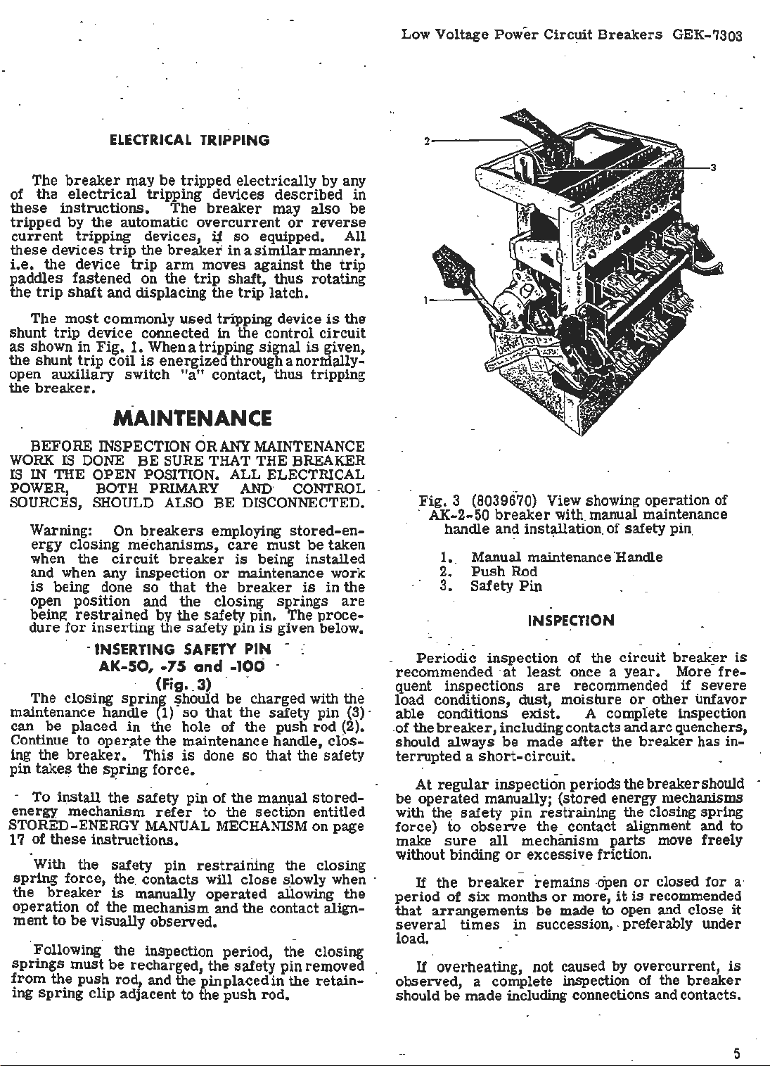
Fig. 3 {8039670) View showing operation of
· AK-2-50 ·
breaker
with manual maintenance
handle and installation. of safety pin,
1.. Manual maintenance 'Handle
2.
Push
Rod
3.
Safety
Periodic
recommended ·
quent inspections
Pin
INSPECTI
inspection of the
at
least
once a
are
recommended
load. conditions, dust, moisture or_
-
able conditions
.of the
breaker,
should always
exist.
A complete inspection
including contacts and
be
made
after
terrupted a short-circuit.
At
regular
be
operated
with the
force)
make
fo
sure
without binding
If
the
period
that
of
arrangements . be
several
inspection periods the
manually; (stored energy mechanisms ·
safety
breaker
pin
observe
all
or
six
months
restraining the closing spring
the contact alignment and to
mechanism
excessive friction.
remains
or
more,
made to open and close
times
in succession, . preferably under.
load.
If overheating, not caused by overcurrent,
observed, a complete inspection
should
be
made including connections and contacts.
ON
parts
-open
circuit
year.
other
arc
the
breaker
breaker
move freely
or
closed
it
is
recommended
of
the
break~r
· More
if
fre-
severe
unfavor
quenchers,
has in-
should -
for
breaker
is
a·
it
is
5
Page 6
GEK-7303 Low Voltage
Power
Circuit
Breakers
TROUBLE
Overheating
to Trip
Failure
AK-2
Breakers
Failure
to
AK-3
Breakers
Trip
TROUBLE
SHOOTING
CAUSE
Contacts not aligned.
Contacts
with
Contacts
dirty,
greasy
burned
or
or
dark
film;
badly
Current-carrying surfaces
coated
pitted.
dirty.
Corrosive atmosphere.
Insufficient bus
Bolts and nuts at terminal connections
uot
tight.
Current in excess
or
cable capacity.
of
breaker rating.
Excessive ambient temperature.
Inductive heating;
of
Travel
positive release
Worn
- Binds in overcurrent
Loose
Disconnect Plugs.
Loose
Tap Connections. -
tripping device does not provide
gt tripping latch.
or
damaged
or
or
trip
unit
parts.
trip
de.vice._
Disconnected Power Sensor
Broken Power Sensor Coil
·
REMEDY
Adjust contacts.
Clean contacts.
Rep~ace contacts.
Clean
surfaces
carrying
Relocate
enclosure.
Increase
Tighten, but
limit
of
breaker
Check
circuit
of
parta.
or
capacity
bolts
by
current-
proVide adequate
of
bus
do not exceed,
or
fittings.
application
_decreasing load. _
or
or
cable.
elastic
ProVide adequate venWation. C~rrect
bus
or
· cable arrangement.
Re-adjust
Replace
Replace
Tighten
Plugs.
Tighten
or
_ replace tripping device.
trip
unit.
overcurrent
or
Reconnect Disconnect.
or
Reconnect Tap Connections.
trip
device.
modify
__
False
Tripping
AK-2
Breakers
False
AK-3
Failure
and Latch
Burned
Contacts
Tripping
Breakers
.
to
Close
Main
Overcurrent pick
Overcurrent time setti!)g too
Bind
in
overcurrent trip device.
Captive Thumb Screw
Loose Fail-Safe Circuitry Reverts .
Characteristic to Minimum Setting
and Maximum Time Delay.
Tap Setting Dial on Power Supply
Incorrectly Set.
External Ground Sensor Coil
Improperly Connected.
Binding in attachments preventing
resetting
Latch out
return
Latch
Hardened
Safety pin left
up
too low. _
on
of
latch.
of
adjustment.
spring too weak
or
gummy lubricant.
in push rod.,
short.
Power Sensor
or
broken.
Motor burned out.
Faulty control circuit component.
Improper contact sequence
not sufficienUy parted
part).
Short.circuit
rupting r.ating
of
contact wipe
Loss
.
current
of
breaker.
when
leJel
or
pressure.
(main contacts
above
arcing contacts
inter-
Check application
trip
deVice. ·
Check appllcatiOn
trip
deVice.
Replace
Setting.
Set Dial
Sensor Coi! Tap.
Refer
of Shield and Conductors Connecting
the
overcurrent
Tighten Thumb Screw on
to Correspond with Power
to
and Connections. Check Continuity
Fig.
External
of
overeurrent
of
overcurrent
trip
device.
Desired
40 Page 38
Ground Sensor Coil
for
Pola_rity
Re-align and adjust attachments.
Adjust latch,
~eplace
spring.
Clean bearing
and
latch surfaces,
Remove safety pin,
Replace motor.
Replace
Increase
contact sequence by raising
ing
main
ReQuires
replacement
quate interrupting capacity.
Replace
and
dress
,.
-
or
adjuat faulty device.
arcing contact wipe. Adjuat
movable
stationary contact
contact pivot block.
system
study
With
breaker haVing
. up
or
replace contacts. _
and
or
lower-
possible
springs
ade-
6
Page 7

At
all. times
pencil
ials
breaker
lines,
to
remain
as
they may
points of different potential and
electrical
The
at
a
circuits
electrical
~reakdown.
breaker
rated
are 'properly
attachments
it
is
important not
paint,
oil
or
on the insulating
cause
should-
voltage
be
to
assure
connected and
are
.other
foreign
surf
low
resistance
result
operated
that the control
functioning
to
·permit
aces
in
several
that
properly.
A complete contact inspection, including con-
tact
wipe and ·
lar
inspection
short
circuit
determine
pitted
or
in
replaced.
quenchers
ing contacts and
replaced
original
erate
and
thickness.
In
general,
lubrication.. _Mechanical bearing points
sliding
regular
G-E
Lubricant
tact
surfaces
ricant
be
using
BE
OF
D50H47. Hardened
removed
kerosene.
REMOVED
DIRT OR
pressure,
periods
current
whether
which
It
to
properly
when they
the
surfaces
inspe
_ction
D50Hl~ . Sli<lingsilver plated con-
should
from
ALL
TO
DUST
should be made
and always
has been
the
contacts
case
is
they should be
necessary
to
inspect the contacts.
arc
quencher
are
LUBRICATION
circuit
barriers
eroded to half
breaker
should be lubricated
periods
be
with a thin film of
lubricated with G-E Lub-
grease
latch
and bearing
EXCESS
AVOID ANY
LUBRICANT
. ·
after
interrupted,
are
worn
remove
should be
requires
and
dirt
surf
ACCUMULATION
mater-
of the
between
eventual
times
all
at
regu
-
a known
to
or
dressed
the
arc
Arctheir
mod-
at
the
should
aces
by
SHOULD
Low Voltage
5. Remove the auxiliary
··
(5-,
Fig.
20).
6. Check along the·
anical
interference
overcurrent
Power
Circuit
or
trip
device and the
Breakers
switch
trip
shaft
connection between the
Remove mechanical · connection if
if
interference
removing
to
avoid mechanical breakage of
or
reassembling
frames
the
should
trip
shaft
NOTE
:
be
fastened to a suitable maouting
the
front
as
the bolts
BASIC
The
arc
regular
cracked
thickness, they should be
inspection
1. Be
or
sure
exists,
re-assembling
use
extreme
front
and
trip
the
front
and
rear
frames,
be
is
hori
zontally aligned.
It
is
recommended
frame
supported by a sling
are
being installed.
BREAKER
ARC QUENCHERS
(Fig •.. 4
positioned
vertically
that
COMPONENTS
and ·5)
quenchers should be inspected
period.
eroded to one-half
REPLACEMENT-AK
the
breaker
If
rep_lacec;i
BREAKERS
is
open.
the
their
.
2. Remove the channel-shaped retaining
by removing two
3.
Lift the quenchers
arcin
g co~tacts.
screws
and two
clear
nuts.
of the· movable
GEK-7303
operating
for
trip
present,
care
back
rod
a mech-
paddles.
or
when
frames
devices. In
the two
so
that
the
breaker
base
with
or
hook
at
the
barriers· are
original
bar
The
use
should
become
destroy
be
entangled
the
On drawout
disconnect
Grease
Specificati~n D50H47. .
To
repair
anism, ox:
frame
must
To -separate
1. · _ The
the
safe!}7
2.
_
part
from
using a
include
Remove ·the two opening
o! the
3.
Remove the clevis pin (14,
the
center
4.
Remove the
socket
the
of
cotton waste to wipe
avoided,
as
under
the cotton ravelings may
the
bearing
bearing
surfac.e of the bearing.
breakers,
studs
SEPARATION OF FRONT
the
should -be
AND
or
replace
overcurrent
be
separated
the two
breaker
pin
in
place.
the contact
greased
REAR
FRAMES
contacts·, operating mech-
devices, the front
from
the
frames
contacts
pro~eed
must
(See MAINTENANCE.)
springs
~reaker)
from
the
outside
Fig.
pole unit.
six
nuts
from
wrench with an extension.
two nuts
at
the top of the
surfaces
surfaces
surface
· with G-E
back
as
follows:
be
open with
(on
pole units.
6)
(13, Fig.
the back
and
of the
frame.
lower
7)
frame
These
frame.
4.
.During _replacement be careful
overtight~n the
shaped retaining
will bow the
cher
loose. · · ·
·
The
is
breakers
except
the
center-pole
similar
that
breaker
to· the
and
the
open and the
Replace the
Type AKF
1. Be
breaker
sure
screw
bar
REPLACEMENT-
arc
is
replaced
breaker
which
bar.
Overtightening the
and leave the
arc
quencher of
·AKF
secure
center
BREA~ERS
these
quenchers of the standard
in a
similar
must be closed. With
closed the center-pole contacts
arc
quencher can be remov.ed.
outer-pole
as
follows:
the
breaker
arc
quenchers of the
is
open.
r.iot
to
the channel-
screws
arc
quen-
breakers
manner,·
are
2. Remove the two channel-shaped r_etaining .-
bars
which
bear
against the front of the
arc
quenchers by removing four -screws, two on each
side.
3.
Lift .the
-
arc
quenchers
clear
of
the movable
arcing contacts.
arc
4. Replace
screws
quenchers and
holding the retaining
insert
bars
the
four
in position.
Page 8
GEK-7303 Low Voltage
Power
Circuit
Breakers
. . . . . .
1·· 2
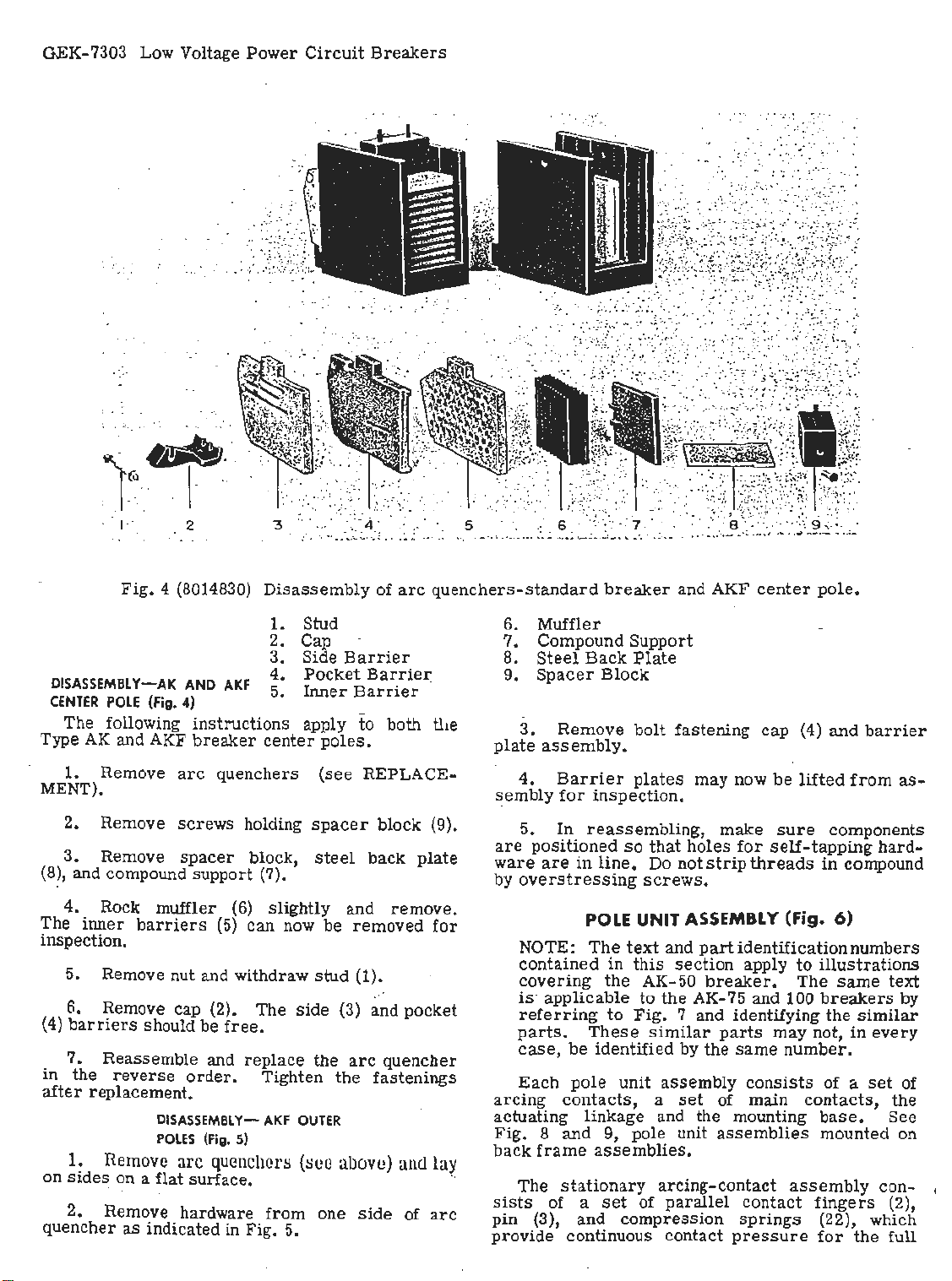
Fig.
4 (8014830)
Disassembly
1. Stud
2. Cap
3. Side
DISASSEMBL
CENTER
POLE
The following
Type
AK
and AKF
1. Remove
MENT).
2. Remove
3. Remove
Y~AK
(Fig.
AND
4) -
instructions
breaker
arc
quenchers
screws
spacer
AKF
holding
block,
4.
5.
center
(8), and compound support (7).
4. Rock muffler
The
inner
barriers
(6)
slightly and
(5)
can now be
inspection.
5. Remove nut and withdraw
6. Remove cap (2). The
(4)
barriers
7.
in
the
after
replacement.
1.
on
sides
2. Remove hardware
quencher
should be
Reassemble and
reverse
DISASSEMBLYPOLES
Remove
order.
(Fig.
arc
quenchers
free.
replace
Tighten
AKF
5)
on a flat surface. ··
from
as
indicated in Fig. 5.
.
..
. :
..
.
. .
,,
, '
Pocket
Inner
apply
poles.
(see
spacer
steel
stud
side
the
OUTER
(8Ce
one
:;.:
:·::··:
~--
.·. : ·· ...
.. .
of
Barrier
Barrie~
Barrier
to
both
REPLACE-
block (9).
back
removed
(1).
(3) and
arc
quencher
the
fastenings
abov
e)
side
. . :
.-
: :
.
arc
quenchers-standard
tl1e
plate
sembly
plate
are
ware
by
remove.
for
pocket
arcing
actuating linkage and the mounting
Fig. 8 and
and
of
lay
arc
back
sists
pin
provide
breaker
6. Muffler
7. Compound
8.
Steel
9.
3.
Back
Spacer
Remove
Block
assembly.
4.
Barrier
for
inspection.
5.
In
reassembling,
positioned
are
in
line.
overstressing
POLE UNIT A
NOTE:
contained
covering
The
in
the
is· applicable
referring
parts.
case,
Each
to
These
be
identified
pole
contacts,
9, pole unit
frame
The
assemblies.
stationary
of a
set
(3), and
continuous contact
and AKF
Support
Plate
bolt
fastening
plates
so
that
holes
Do not
may now
strip
screws.
SSEMB
text
and
this
AK-50
to
Fig.
part
section
breaker.
the AK-
7 and identifying
similar
by the
unit
assembly
a
set
arcing-contact
of
parallel
compression
center
cap
be
make
sure
for
self-tapping
threads
LY
(Fig. 6)
identification
apply
to
The
75
and 100
parts
may not, in
same
number
consists
of mai~
assemblies
assembly
contact
sprin
gs (22), which
pressure
pole
.
(4)
and
barrier
lifted
from
· components
in
compound
numbers
illustrations
same
breakers
the
similar
every
.
of a
set
contacts,
base.
mounted on
fingers
for
the full
as-
hard-
text
by
of
the
See
con- ,
(2),
Page 9

Fig.
5 (8019408) Disassembled
GEK-7303 Low Voltage
arc
quencher- AKF
outer
Power
poles.
Circuit.Breakers
1. Muffler Assembly
2.
3.
Spacer
Inner
Block
Barrier
4. Cap
travel
the pivot pin to
pivot point when interrupting high
earlier
· of · the
model
contacts.
pr
_event possible pitting
breakers
Steel
flexible
springs
(5)
currents. · On
braid
leads
shunt
at
the
were
used.
rhe
movable ~rcing-contact a~sembly consists
of
parallel
·able pivot
contact
pins
arms
(8)
and (19). The
(4)
carried
arcing
on two mov-
con.tacts
interleave the main · contacts and pivot with them
about pin (19).
linkages
from
the
relative
upper
motion
pin
(7)
is
obtained by.
to the
breaker
This
mechanism. . . ·
stationary
Th·e
main and
contact
and will,
and
intermediate
surface
therefore,
break
of contacts
in
Table
I.
after
main contact
contacts. The
assembly
intermediate-
includes
extends beyond the main contacts
make
before
the main contacts
the main contacts. The number
for
each
breaker
rating is· given
The movable main contacts pivof around a
stationary
lower
pin
.(7), connected by an insulated
breaker
shunting
lower
!the
con~cts
liiie
at
the
jassembly
pin (18), which holds
·block. Motion
mechanism.
the
current
is
In
from the contact ·
contact block,
pivot
also
ag~nst
pomt. The movable main contact
the pins to prevent pitting
contains main and intermediate
obtained
addition to
steer
springs
them
from
link
ste·e1
. to the
a second
(12). to tl\e
springs
directly
(17)
force
!contacts.
5. Intermediate
6.
Outer
. 7. Side
In
of contact
Plate
order
Barrier
to function
pressure
between . the movable and
Table I gives the
contact wipe. Both wipe and
cpecked during the_
MEASURING
· 1. Remove
ARC
under
QUENCHER). .
2. With the
zontal distance
contact to the
dim.
for
arcing
contacts). ·
3. Clo.
se
the
difference between the readings in items 2 and 3
to
determines
reasons
breaker.
1. Remove
UNDER
the wipe of the · contacts.
be extremely careful not to trip the
· . ·
MEASURING
(Fig.
ARC
QUENCHER).
2. Close the
"B".
3.
Open the breaker.
Barrier
properly,
a definite amount
and contact wipe must
stationary
figures
for
contact
pressure
regular
CONTACT
arc
quenchers
breaker
from
. the edge of the stationary
stationary
WIPE
(see
open,
block behind
contacts, "C" dim.
breaker
and repeat
inspection period.
(fig. 6)
REPLACEMENT
measure
contacts.
pressure
should be
the hori-
it.
for
item
For
CONTACT
6)
arc
quenchers (see REPLACEMENT
breaker
PRESSURE
and measure dimension
Place
a push-type
exist
and
-:
('.'B"
.main
2. The
safety
scale
Page 10
Low Voltage Power Circuit
Breaker ontacts
Type
No.
Per
Breakers
Main Contacts - Intermediate Contacts
or
Pole
GEK-7303
Pres-
sure
In In
Lba,
Wipe
Inches
TABLE
No.
of
Contacts
Per
Pole Lbs,
Pres-
sure
In
Wipe No.
Inches
ln Contacts
of
Per
Pole Lbs,
Arcing Contacts
Pre=r-
sure
In
Wipe
Ill
lnches
AK-SO
tor
AC
AK-SO
tor
DC
tor
AK-75
AK-75
AK-I
AK
_ AKF-2C
-
AKF-2D (Outside
AKF-2£' (Poles)
AKF•2C (Field
AKF-2D Discbarge
AC
tor
DC
00
for
AC
-100
tor
DC
(Oulside Poles
Contacta)
• The intermediate conta~t
~
•
Ldt
stationary contact ext;nda approximately 3/32 in. ~ 1/32 further than right band contact.
-
·:
..
3 55
3
55
5 35 to
-
"
35
5
-
8
25
3 55 to
.•.
.
5 55 to 65:.
0
-------
wipe
to
65
to
65
45
to
45
.
to
35
65
should be
4/64 to
. '1/64
1/16 to
'1/64 .
1/16 to
7/64
1/16
?/64
1/16 to
?/64
1/16 to
'1/.
64
1/16 io
'1/64
-----
at
le~t
to
.
.
1/16
1 55 to
1
1
I 35
2
1,
I
0
in.
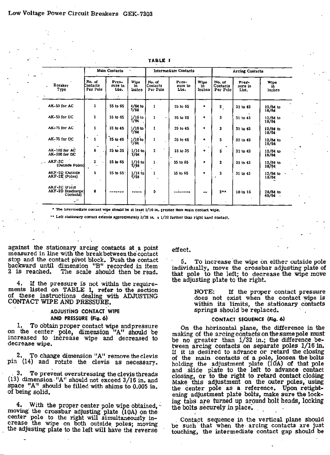
against the stationary arcing contacts at . a point
in
measured
line with the breakbetweenthecontact
stop and the contact pivot block. Push the contact
backward until dimension ."B" ·recorded in item
2
is
reached. The
4.
If
the
ments
listed
pressure
on TABLE
of these instructions dealing with
CONTACT
1. To obtain
on the
WIPE
ADJUSTiNG
AND
center
scale
should then be read.
is
not within the
I,
refer
to
require-
the section
ADJUSTING
AND
PRESSURE.
PRESSURE
proper
·coNTACT.
contact wipe andpressure
(Fig.
WIPE
6)
pole, dimension "A" should be
increased to increase wipe and decreased to
decrease wipe.
· 2. To ch.ange dimension "A" remove the clevis
pin
(14)
and rotate the clevis
as
necessary.
. 3. . To prevent overstressing the clevis threads
(13)
dimension. "
space.
'.'A"
should
A"
should not exceed 3/16 in. and
be
filled with shims to 0.005 in.
of being solid.
4.
·
moving·
With the proper
the
crossbar
center pole to the right will simultaneously
crease
the wipe on both outside. poles; moving
the adjusting plate to the left will have the
center
pole
WiJ>e
adjusting plate
obtained,:.
{lOA)
reverse
on the
in-
-
-
to
to
to
-
to
.
greater
.
65
55 to 65'
35 to 45
to
45
25
to 35
55
to
65
55
to
65
-----··--
than main ·contact wipe.
•
.
•
•
•
• ·
--
2 31 to 43
3
31
3
31
5
31
-
5·
31
2 31
3
.
31
2
..
10
12/64 to
18/64
-
to
43 12/64 to
to
43 12/64 to
to
43
to
43
to
43
to
43
io
16
18/64
18/64
12/64
18/64
12/64
18/64
12/64
187?4.
12/64 to
18/64
28/64
40/64
effect.
5.
To
increase
individually, move the
that
pole
to
the
the adjusting
plate
NOTE:
does not
within
springs
CONTACT
On
the
horizontal plane,
making
be
tween
If
of the arcing contacts
no
greater
arcing
it
is
desired
·the wipe on
left;
to
If
exist
its
limits,
crossbar
to
the
right.
the
proper
when
either
outside pole
adjustin~ plate of
decrease
the wipe move
contact
the
contact
the
stationary contacts
should be replaced. ·.
SEQUENCE
(Fig. 6)
the
difference in the
on
the same pole must
than 1/32 in.; the difference
contacts on
to advance
separate
or
retard
poles 1/16
of the main contacts of a pole .loosen the bolts
holding the adjustment plate
slide
and
closing,
Make
center
the
plate
or
this
adjustment on the
pole
to
to
the right to
as
the left to advance
a reference.
ening adjustment plate· bolts,
ing
tabs
are
turned
the bolts
. Contact sequence·
be such ·
touching,
securely
that
when the. arcing contacts
the
intermediate contact gap should be
up
a:r:ound
in
p~ace. . . .
in
the
(10A)
retard
outer
make.
bolt
vertical
of
contact
poles, usmg
Upon
sure
heads,
plane should
pressure
y.,ipe
is
~e~
m.
the closing
that pole
con~ct
~los~g
retight-
the lock-
locking
are
just
Page 11
Low Voltage
Power
Circuit
Breake~s
GEK-7303
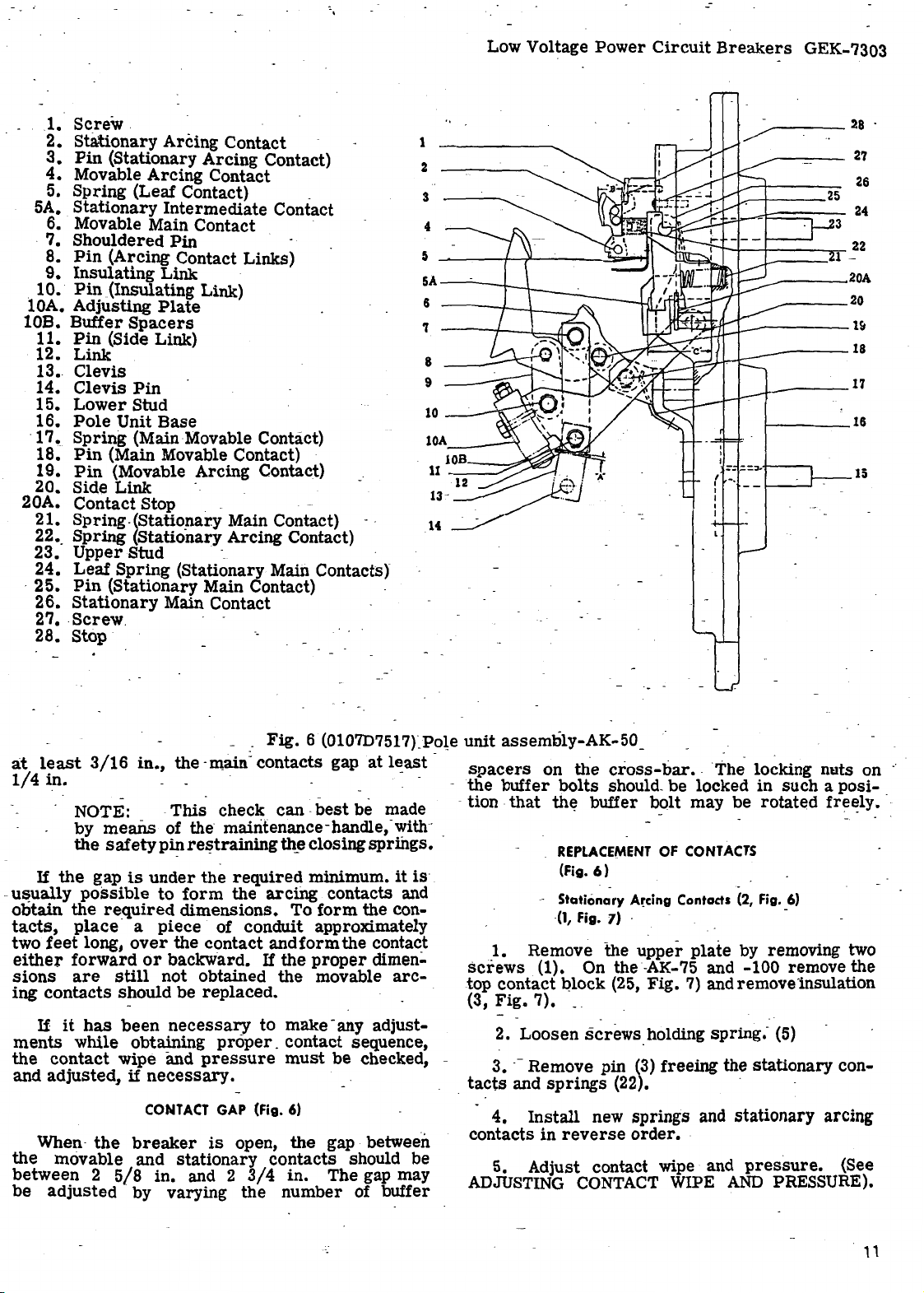
1.
2.
3.
4.
5.
5A.
Screw
Stationary
Pin
Movable
Spring
Stationary
.
Arcing Contact -
(Stationary
Arcing
Arcing
Contact
(Leaf Contact) _
Intermediate
6. Movable Main Contact ·
.
7.
Shouldered
8.
Pin
(Arcing Contact Links)
Insulating
Pin
(Insulating Link)
.
9.
10.
lOA. Adjusting
10B.
Buffer
11.
Pin
12.
13.
14.
15.
16.
·
17.
18.
19.
20. Side
20A.
21.
22 •.
23.
24.
·
25.
26.
27 • .
28.
(Side Link)
Link
Clevis
Clevis
Lower
Pole
Unit
Spring
Pin
(Main Movable Contact) ·
Pin
(Movable Arcing Contact)
Link
Contact
Spring
Spring
Upper
Leaf
Spring
Pin
(Stationary Main Contact) -
Stationary
screw
Stop
Pin
Link ·
Plate
Spacers
Pin
Stud
Base
(Main Movable Contact)
- _
Stop . - · -
-(Statio:f1ar.y Main Contact) - (Stationary Arcing Contact)
Stud -_ ·
(Stationary Main Contacts)
Main Contact
.
Contact)
Contact
1
2
3
4
5
~---t-..,,._---.....::,aa-...,
5A-~--t---\----~-
6
'l
8
9
10
-----
lOA
____
,
-
~
---------
•--r--+---+----...--
~~f/r:J__..-------1~
=-
{ -.
I
I
.J.------~l
______
___
----18
1-----16
.:=.;,,.-i----,
28
27
26
22
-
20A
20
15
·
a:t
least
1/4
3/16
in.
NOTE: -
means
by
the
safety
If
the
-
usually
obtain
tacts,
two
either
sions-are
ing
contacts
If
ments
the
and
When·
the
gap
possible
the
re_quired
place
feet
long,
forward
still
it
has
while obtaining
contact
adjusted,
the
movable and
between 2 5/8
be
adjusted · by
in.,
the ·main: contacts gap
This
of the
pin
is
under
to
form
dimensions.
a
piece
over
the
or
backward.
not
should
been
be
necessary
wipe and
if
necessary.
CONTACT
breaker
stationary
in.
varying
.
Fig.
6 (0107D7517rPote
check
- -
can . best
be made
m~~tenance-h~dle,-~ith
rel?trammg
the
th_e
required
the
arcing
'FO
closing
minimum.
contacts and
form
of conchnt approximately
contact
obtained
and
If
form
the
the
the contact
proper
movable
replaced.
to
make -any adjust-
proper_ contact
pressure
GAP
(Fig.
is
open,
contacts
and 2
3/4
the
must
6)
the
in.
number
sequence,
be
checked, -
gap - between
should be
The gap may
of buffer
at
l~ast
springs.
it
is
~e
con-
dimen-
arc-
unit
-
spacers
-
the
-tion
- _
screws
.top
(3,
tacts
.
contacts
ADJUSTING
assembly-AK-50
on
the
buffer
bolts
that
th~ buffer
REPLACEMENT
(Fig.
- Stationary
(1,
Fig.
1. Remove
_
cross-bar
should.
6)
- .
A~cing
7) -
the
upper
• . The ~ocking nuts
be
locked m
bolt
may
OF
CONTACTS
Contads (2,
plate
be
by removing two
. (1). On the -AK-75 and -100 r~move
contact
Fig.
2.
3 • . - Remove pin
4.
5. Adjust contact wipe and
Qlock (25,
7).
- .
Loosen
and
__
screws
springs
Install
in
reverse
CONTACT
Fig.
7)
and remove insulation
holding
(3)
freeing the
spring.
(22). · ·
new springs and
order.
WIPE
stationary
·
AND
stationary
pressure.
such
rotated
Fig.
a pos1-
fre~ly.
_6)
- (5)
arcing
PRESSURE).
<?D
~e
con-
(See
,,
Page 12
GEK-7303 Low Voltage Power
4
5
Circuit
Breakers
· I
l
I
I
I
I
I
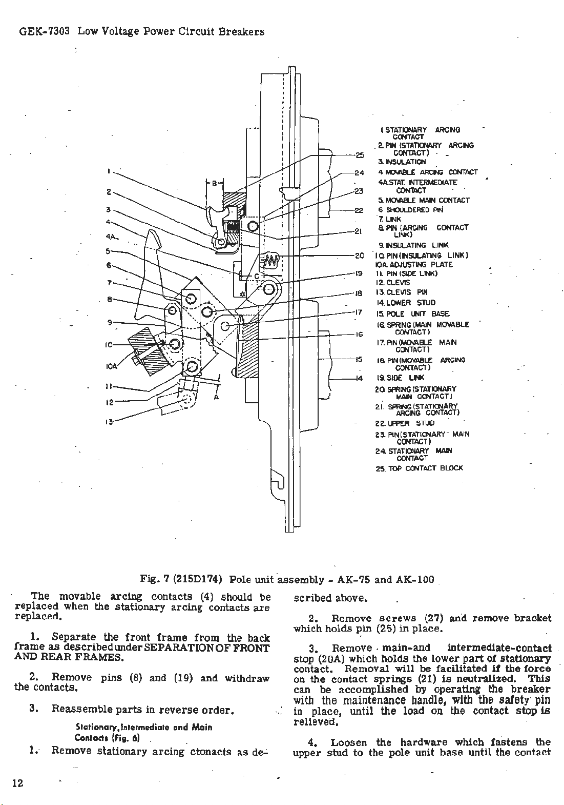
STATIONARY
COOTACT
.
2.
P1N
(STATIONARY
25
24
23
22
21
20
19
18
17
16
5 -
4
-
CONTACT)
3. lNSULATI
4. ID.ABLE
4A.
STA
T.
CON'lllC
5.
MOI.AB.E
6
SHOULDERED
7.
LNK
a
PIN
(ARCING
LINK)
9.
INSULATING
I Q PIN ( INSll.ATING LINK )
IO
A.
A.OJUSTING
II. PI
N (S
12.CLEVIS
13. CLEVIS PIN .
LOWER
14.
15.
POLE
16.
SPRING
CONTACT)
17. PIN(MOVAEl.E MAIN
COOTACT)
1a
P1N(MOV
C
ONTACT)
19 SI
DE
2Q
SPRING (
MAN
2i
. ~ (
ARCING
-22.
Uff>ER
2
3.
PIN(STATIONARY-MAIN
CONTACT)
24.
STATICNARY
CONTACT
25. TOP COOTACT
"ARCING
-
-
OO
ARCf'.lG
NTERMEDIATE
T
MAN
CONTA
PIN
CONTACT
LINK
PLATE
IDE
.LI
NK)
STU
D
UNIT
BASE
(MA
IN
MOVABLE
ARCING
ABLE
LN<
STATIONARY
CONTACT)
STATIONARY)
CONTACT
STUD
MAl'l
BLO
ARCING
CO'JT
ACT
CT
CK
The . movable
replaced
replaced
1.
.
frame
AND
as
REAR FRAMES.
2. Remove
the contacts.
3.
1.- Remove
12
·
Fig
arcing
when the
stationary
.
Separate
described
Reassemble
the
front
under SEPARATION
pins
(8) and (19) and withdraw
parts
in
Stotio~ory,lntermediate and Ma
Conta
d1
(Fi
g. 6) _
stationary
. 7 (215D174)
contacts
(4)
arcing
frame
reverse
arcing
from
order
in
ctonacts
Pole
should
contacts
the back
OF
FRONT
.
.
as
unit ·
be
are
de.;.
assembly
scri
- AK-75 and AK-100 .
bed above.
2. Remove
which holds
3.
~in
Remove .
stop (20A) which h.olds
contac
t.
Removal
on the contact
can
be
accomplished
with
the maintenance
in
place,
·
relieved.
until
4. Loosen
upper
stud
to
the pole unit
screws
(25)
(27) and remove
in
place
•
main-and
the
lower
will
be
springs
facilitated
(21)
is
by operating the
handle,
the
load on the contact
· ·
the hardware
base
bracket
intermediate-contact
part
of
stationary
if
the
neutralized.
force
This
breaker
with
the
sa!ety· pin·
stop
is
-which
until
fastens
the
contact
the
.
Page 13

Fig.
8 (8014678)
Front
view of back
assembly
- AK-2-50
frame
Low Voltage
Power
Circuit
Breakers
GEK-7303
Stationary
1.
Contact
Movable
2.
Contact
Stati9nary
3.
Contact
Clamp
4.
Movable Main
.
5.
Contact
spring
lift
5.
out
. ·
load
Remove
contacts.
~--Reassemble
being
in
described
at
th~
·
1.
2.
3.
·
bottom
careful
proper
Remove
above.
Loosen
Remove
of
Arcing
Arcing
Main
:
on
pin
pin
to
position.
Movable
_
Main
the
spring
braid
contact.
(25)
is
(~5i and
contact.s
replace
Intermediate
Contacts
movable
(17).
if
6.
Crossbar
Series
7.
Device
Movable
8.
mediate Contact
Stationary
9.
_mediate Contact
relieved.
screws
in
the
intermediate
(F1g.
and
6) ·
arcing
present
by
· ·
Overcurrent
Inter-
Inter-
(27)
and
reverse. orger,
contact
·
contacts
removing
as
screw
Fig.
9 (8039669)
1.
.
2.
·
3.
ing contact
Power
Disconnect
Tr;msformer
replacement
Front
·. ··
assembly -AK-3-50
Sensor
view of
Coil
Assembly
Plug ·
Taps
in
!
.
back
Amper~s
frame
(See ADJUSTING CONTA_CT WIPE AND PRESSURE).
OPERATING -MECHANISMS
ELECTRICALLY
and
.
The
ele~trically
a
motor
the closing
shaft (14,
with a
closing
closing
llC.
and
center-pole
crossbar
.
of the
contacts
-100;
and a
Fig.
roller
cam
cam
it
OPERATED
MANU~L
gear
springs
10). The
(12,
(2,
Fig.
roller
The
closing
unit
through a
controls
~m
all
AK ·
.AK-50,
-50
-75
·
operated · mechanism
reduction
(16,
Fig.
11).
is
shown in·
unit,
Fig.
10) through a
crank
shaft
10) which
The
which charges ·
ha~ an
rides
position· of
Fig.
11A,
cam is. connected to the
clevis
and through a
the opening and closing
pole
units.
includes
crank
arin
on the
this
11B,
4.
(7).
5.
sid~
to
be
6.
Always
Slide
link
Slide ·pins
to
allow
replaced.
Reassemble
check
(12) to the
(7)
the
movable
parts
contact wi
and (18)
intermediate
in
reverse
pe
and
side
and off of p4l
far
enough
order.
pressure
to
the
contacts
follow-
1.
The
Fig.
llA.
2.
The motor turns the crank
is
mounted
tion unit.
face of
on
it.
Chargi
ng
mec~anism
on
The
the
crank,
the Closing Springs (Fig.
in
position
the
output
charging
has
shaft
roller,
paddle
of
arm
10)
is
the
gear
which
(11)
shown
(10)
is
in
which
reduc-
on the
bearing
13
..
Page 14
GEK-7303 Low Voltage
Power
Circuit
Breakers
·
~C>IANSM
RESETTING
FIG
~
·IIA
N
t.1111:lN"
AS
SHOWN IN.
BEFORE
FIG.-
I I B
~CHANSM
FIG.-
N
116
RES€T
POSITlCN
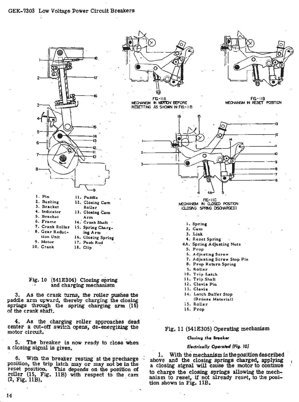
3.
paddle
springs
of the
_5
6
7
Pin
1.
Z..
Bushing
3,
Bracket
4 .
Indicator
5.
Bracket
6.
Frame
7,
Crank
8,
Gear
tion
9.
Motor
10,
Crank
Fig.
10 (541E304) Closing
· · and
As
the
arm
upward, there~y
through the
crank
shaft.
Roller
Reduc
Unit
crank
11,· Paddle
lZ.,
13.
1'4:
15.
..
16.
17,
18,
chargin
turns;
spring
15
14
13
·12_
II
IO
··-
~-
Closing
Roller
Closing
Arm
Crank
Spring
ing
Closing
Push
Clip
g mechanism
the
Cam
Cam
Shaft
Charg-
Arm
Spring
Rod
spring
roller
chargi~
charging
·
pushes the
the closing
arm (15)
13
~2
2
3
Spring
.•
Cam
Link
Reset
Prop
Adjus.ting
Adjusting
Prop
Roller
Trip
Trip
Clevis
Clevis
Latch
(Bronze
Roller
Prop
FIG.-IIC
N
a..osED
SPRf'lG
Spring
Adjusting
Return
Latch
Shaft
Pin
Buffer
POSITl()'.I
ClSOtARGED)
Nuts
Screw
Screw
Stop
Spring
Stop
Material)
Pin
tJE:CHANSM
(CLOONG
1.
z.
3.
4 .
4A,· Spring
5.
6.
7.
8.
9.
10.
11.
lZ..
13.
14.
15.
16.
()
···
--9
-8
·7
6
4.
As
center
motor
5. The
the
a cut-off
circui
t.
breaker
a closing signal
6. With the
· position, the
reset
roller
(2,
14
position.
(15,
Fig
. 11B).
. charging
switch
is
breaker
trip
This
Fig.
llB)
is
roller
opens,
now
approaches
de-energizing
ready
to c
given.
latch
resting
may.
or
at
may
depends on. the position
with
respect· to
lose
the
precharge
not be
the
dead
the
when .
in
the
of
cam
1.
··
above
a
closing
to
charge
anism
tion shown
Fig.
11 (541E305) Operating mechanism
With
and
to
reset,
Closing
Electrically
the
the
signal
the
in
Fig. UB.
the
Operated
mechanism
closing
·
will
cause
closing
springs
u· not
halter
in
the position
springs
the motor
already
(Fig.
charged, applying_
allowing
resP.t, to
10)
described
to
co
ntinue
the
mec~-
the
posi-
Page 15

Low Voltage
•1:
.
Power
Circuit
'
..
Breakers
. . ' ;
.. ~ ..
': .
...
~. ··
GEK-7303
:··
·•. -
Fig.
1i
(8018989)
AK-50 showing
~
2.. As
dead-center
position) the
Crank (10)
motor so-
center
·
3.
the
crank
to
rotate
F.ig.
11).
llC)
in
4. Raising
breaker
Tripping the Breaker (Fig.
·Operation
the
trip
to
release
forces
reposition
the
position
the operating ·
Adjustments (Fig.
the
crank. roller
position,
closing
can
be
that
roller
position
As
this
without
the
springs
shaft
cam
Prop
position
'(14)
(2,
(16,
clevis
contacts
of
-any
shaft
(11)
the
latch
of the· contact and opening
the
operating
shown
cycle
11)
Rear
view of
cam
shaft
locking plate
being loosened
(7)
(maximu.m
springs
overdriven
(7)
are
independently of the
assumes
restraint.
free
its
:-
discharge,
causes
Fig.
Fig.
roller
11) and
11) holds
raise
~
(13,
Fig.
llC)
through the pole
11)
of
the
trip
devices
which ;µlows
prop
(5).
the
This
mechanism linkage to
in
Fig.
may
llA,
be
repeated.
In
fronnrame-
passes
spring
its
charge
to
discharge.
top
bottom dead-
the rotation of
(15,
Fig.
11)
clevis
cam
closes
base
(13,
(2,
Fig
the
linkage.
rotates
trip
latch (10)
allows the
springs
this
position,
to
Fig.
manual
and with
roller
1/64 in, and
obtained by
should
.
latch
be
reposition
(3) and
1/
32
the nuts (4A)
.the
Replacement
to the
AND
these
..
.!:.:
Fig.
13
(8018984)
AK-50 showing
~nd
llB.
(The mechanism should
operation
1.
roller
The
(9) of
(15)
gap between.the
the
1/32
turning sc.
2.
·
The
center
pass
through
buffer
stop
adjusted by loosening the retaining
the
3.
The . distance
prop
in.
reset
(5) should be between 1/64 in. and
To
obtain this gap, advance
spring
Rear
view of front
cam
shaft
cam
shaft
removed -
with_ the safety pin
clear
of
cam-(2).
trip
reset
the
latch should be between
in.
This
rew
(6).. - · -
line
of the
center
of the
on the mechanism
latch
with respect to the
between ·the
on
-the bottom of the
(4).
frame-
locking
plate
be
reset
in
latch
(10)
adjustment can be
trip
latch (10)
roller
(9). The
frame
screws
roller
or
~d
When replacing the operating mechanism,
section
BACK
titled
FRAMES
SEPARATION OF FRONT
under
MAINTENANCE
instructions.
by
place
.and the
can
to
roller.
on
link
retard
~ing
refer
in
All
ting
mechanism· in
adjustments
should
the
reset
be
made with the opera-
position
as
shown in
The
motor
is
mounted on the side of
the
g
ear-
15
Page 16

GEK-7303 Low Voltage
Power
Circuit
Breakers
reduction unit and through a worm
planetary
with a reduction 1000:1. To remove the
and gear-reduction unit, _
1 • . Remove the
OF FRONT
2.
as
illustrate~ iii Fig. -
3. Disconnect the
the -wires attached to
4.
front
unit. The.
NOTE
motor unit, disconnect the
remove only the hardware fastening
. - -gear-reduction unit. When removing the motor
· only, the front
· side
. ·
gear
The
similar
oil
HFS
or
· change oil except when the gear'.'.'reduction
unit-and
g~ar
train
drives
proceed
front
frame
AND
R~AR FRAME.)
.Remove closing
Remove four bolts
frame
No.
QUICK
and one
motor
:
down
unit. ·
gear
3.
motor
and
If
it
is
to prevenJ . the oil escaping from the
. reduction
to Atlantic Refining Company's Grade
·n
should not be
are
CLOSE
springs
12
and 13.
leads
gear
bolt
gear
unit may
desired
frame
unit
disassembled •. -·
the
crank
(see
from
motor and remove
unit housing.
at
the bottom of the
at
top of
to
motor
should be placed
contains 4 ounces of
BREAKER
ADJUSTMENTS
gear
(10, Fig. 10)
as
follows:
SEPARATION
and
crank-shaft
gear
reduction
n!JW
be removed .•
replace
necessary
only the
. leads - and
it
.
and a
motor
to the
front
to add
· .
.'
'c"
Fig
. 14A ·
Quick-Closing
Adjust the engagement of the
to 1/8
adjustment
11
±1/64" by
"B". Adjust the
roller
the
Release
is
set,
clearance
to
1/32+0-1/64
Latch -Fig.
turning
lock
the
by
the
between the
turning
14A
roiler
screw
bolt
on the
"A".
with the hex nut
the
screw
After
latch
latch
and
"C".
The quick close
the standard
_ operati<;m
deadAs
_.!tie
bre_aker, the discharge operation
~
pi:ap
closing operation
the
-latch to
the springs
operation and close the
The
is
· not interchangeable with the
uniLon the quick
close
to relieve the
be
. exerted between the output
the prop. . ·
After the· closing springs have been completely
charged and the prop and latch
venting
tion may
relay.
ually- by
mechanically displaces the latch to allow the
break~r to
On
breaker and enclosure
be
discharged before the
from the
is
extended
center
. . .
position of the closing
springs
and latch arrangement. The subsequent
release
to
gear
reduction unit
gear
reduction unit employs a
closure
be
.accomplished by energizing the closing
thni
the control relay contacts,
depressing
close.
drawout
enclosure.
breaker
breaker
start
is
the
continue the interrupted discharging
close
pressure
of
the
the push to
breakers
basically differs
in
that
~e
to
and slightly
. to discharge~ to close the
accomplished · by tripping
prop
which in
breaker.
for
the
unit because the quick
that would otherwise
breaker,
· .
an interlock between the ··
requires
the closing
breaker
p~echarging
past
spring
is
arrested
turn
standard
gear
crank
system
close
lever
the springs
can be removed
from
the top
assembly.
allows
breaker
reduction
slip
clutch
plate and
are
pre-
opera-
or
man-
which
by
to
D
Fig. 14B
Release Arm Adjusting -
Adjust release arm screw
the
armature
roller
over-travel.
NO
·
from
GO
of the closing
the
latch
with a minimum
·Check. by
gauge between
using
Fig.
l4B
"P"
so that
solen<:>id
1/32"
armature
the
stroke of
releases
GO
and
· and magnet.
of
the
1/32"
3/32"
16
.
Page 17

Fig.
14C
Low Voltage
used
on
theAK-50,
closing
manual
··
The
the
breaker,
case
with
breaker
handle
is
!mu
through
position
degrees
then
clockwise
approximately
stroke
have
which have
strokes
center
spring
and
This
assembly,
ot
mechanism
assembly,
the
closing
Power
-75
springs
closing
instead
the
of
electrical
accomplished
complete
120
degrees
and
then
from
its
back
70
degrees
been
completed,
been
the
closing
the
breaker
ratchet
handle
shaft
handle.
Circuit
and-100
(5)
are
handle
the
(22) on
closing
breaker.
by pumping
cycles,
from
clockwise
normal
through
of
charged
handle,
closes.
consists
wheel and output
and pawl
Breakers
electrical
charged
the
by
front
motor
Closing
the
first
counterclockwise
its
normal
back
through
vertical
120
the
the
during
basically
position
degrees.
fourth
closing
the
are
driven
of a closing
assembly,
GEK-7303
breakers.
operating
of
the
as
is
the
this
operating
vertical
120
and
When
clockwise
springs,
previous
over-
crank
and
Release
Adjust
screw
ta.ken up by
Adjust
"F"
when
the
be
the
to
Shaft Stop and
screw
and
lever
pressing
switchette
under · cotter
armature
The
control
left
side
removed
(3)
two mounting
admit
the
"E"
is
relay
of
the
by
disconnecting
top
keyhole mounting,
should
and
side
The
mo~al of .
re-mstallmg
contact
solder
box
the
Stored-Energy
be
contacts.
The
anti-pump
of
the
connections
the
points
of flux.
The
closing·
solenoid
remotely
replaced
front
to
relay
use
of
control
with
located D switches.
Manual
AK-50-75-100
This
stored-energy
breaker
is
mechanism
Switchette -Fig.
to
with
1/32"
clearance
lever
lightly
operation
pin, · so
adjusted
front
or
that
as
(X)
frame
screws
mounting
in
general,
rather
relay
channel
this
extreme
different
is
is
above
relay
straight
care
voltage
relay
sufficient
Mechanism
equipped
with a spring-charged
similar
clearance
on
forward.
by
adding
contact
shown
relay
channel.
the
wiring,
and
lifting
screw
the
than
changing
located
the
are
soldered.
forward.
to
avoid
consists
linkages
(Fig.
to
14C
between
release
·
washers
is
made
above.
is
located
It
loosening
it
slightly
through
entire -relay
on
the
control
relay.
When
shorting
potential
of a
strong
to
operate
15) ·
the
mechanism
arm
on
may
the
coils
left
Re-
with
Closing the Breaker
The
first
stroke
the
ratchet
(23),
to
(17),
thus
The
subsequent
same
in
the
pawls
engage
beginning
function
ratchet
as
wheel (17),
wheel and output
th
_e closing
springs. This
wheel and output
direction
more
dead
are
at
a high
Inserting the Safety
1f
contacts
operate
as
from
than
-180
center.
free
to
release
speed.
it
is
desired
to
the
described
the
In
check
closing
above.
counterclockwise
the
fourth
pin
(3) into
thus
preventing
releasing
Replacement
1f
it
anism
clockwise
their
(Fig.
'is
necessary
parts,
the
energy
the
recommended.
at
the
step
required
part:
1. ·
Install
the
above.
2.
Separate
described
under
REAR FRAMES"
of
these
instructions.
(Fig.
15)
of
the
closing handle
(21)
the
first
tooth of
to
char
closing
crank
handle
the
pawls
(32) and completely
crank
is
lower· position,
attached
degrees,
this
their
to a position
position
energy,
to the handle
the
ge
the
closing
strokes
(21) engage
thus
rotating
rotation
in a
counterclockwise
through
the
closing
closing
ratchet
perform
of
just
the
· .
Pin
(fig_.
15}
to
slowly
contact
handle 3
At
stroke
stroke,
hole
(4)
the
closing
to
close
15)
to
replace
following total
This
procedure may be.
to
safety pin
the
front and
"SEPARATION
"in
the "MAINTENANCE" sect.ion
close
the
wiEe- and sequence,·
1/2
complete cycles
the
end of
and
before
insert
in
the guide
performing
the
springs
the
bre~er
any of
the
procedure
replace
(3)
rear
OF
any
particular
as
described.
frames
FRONT
causes
shaft
wheel
sprin
the
teeth
the
ratchet
charging
the
ratchet
slightly
beyond
springs
breaker
breaker
the
fourth
safety
rod
(6),
(5) from
contacts.
mech-
halted
as
AND
gs.
the
is
.17
Page 18

GEK-7303 Low Voltage
Power
Circuit
Breakers
I .
;
§Ji
:j
I,
ii
l---+---+-;
H-++--
y.,_--
- 6 -
8-
7
---
------
-
--
-1-;.-.-'i-
-ll
II
ii
:i :!
II
L .. ~ ;
· Fig.
15
1
•.
Upper Spring
· 2, Safety
3.
·
4.
5.
·
6,
7.
·1.
9,
O. Bearing
Pin
Safety
Safety
Closing
Guide Rod 16. Ratchet Wheel Shaft and
Pawl
Front
Front
Holder
Pin
and Chain 13.
Pin
Hole . 14. Groove
Springs
Springs
Escutcheon
Bearing
Plate
·
~-
""'-··-··-,
" ·I
(669D805)
Pin
Plate
;Mounting
31.
Lower
/'
,
'---··- ·
Stored-energy
11. Output
12.
15. Nylok
17.
18. Side
~
Bolts
19. Side
20.
~nrinO' 'Pin
r
Jl
manual closing mechanism
Thrust
Crank
Shims
Screw
Ratchet
Plate
Plate
Be~ring Side
Roller
Bearing
Pin
Wheel 27.
Shims
Mounting Bolts 29. Handle
Plate
,,,,
Asm.
'"'-·
charged
21. Ratchet
22. Manual Closing Handle
23. Closing Handle Shaft and
24
. Roll
25. Main Closing
26. Pawl
Butter
28. Buffer Stop Support
30
. Mechanism
....
··•
,...
___
position AK-2
Pin
Buffer
stop
Return
,.
Pa~ls
Crank
Stop
Shims
Spring
Roller
Pawl
Asm.
.
Page 19

GEK-7303 Low Voltage Power
1. Springs
2. Insulation
3.
Stationary Contact
4.
Pin
.
5. Screw
6. Movable Contact
7.
Pin
8. Buffer
· 9 •.
Crossbar
10. Adjusting
11. Bolt
Plate
12. Buffer
13. Screw
14. Shims
15. Bolt
16. Pin
17. Pin
Circuit
Breakers
6 5 4 3 2
Fig.
17
(227Dl 74) Field discharge c~ntacts
When
pull
outer poles. As the
(A)
toggle links
center-pole contacts through connecting
Link
forming a single
Contact Adjustments
Measurements
of the two outside poles of the
to POLE
the
breaker
crossbar
rotates
(9) downward, opening the
about a fixed
(B)
(C)
consists
For
contact measurements and adjustments
is
tripped, the opening springs
crossbar
and
(C)
of
two
triangular
moves downward, link
center
(17)",
upward, therby closing
links
riveted
· link.
breaker,
UNIT
ASSEMBLY.
Contact measurements of the
center-pole
breaker's
collapsing
link
(D).
together,
refer
field
discharge contacts should be made on the left
contact and be
1. Contact wipe, 3/16 in. to
within
2. Contact
3.
Ga_p
open, 1
between contacts when
1/2
in.
to 1 3/4
the
following
pressure, ·10
in.
7/16
lb. to
limits:
in.
16
lb.
center
pole
is
4. Overlap · between the center-pole contacts
and the
arcing
contacts of the
outer
poles, 3/16 in
to 7/16 in. _ · •
Measurements of the center-pole contact wipe
13
14
(center
and
pressure
procedure
in POLE UNIT ASSEMBLY:· Overlap
may be made by following the
as
outlined
pole contacts and the
may be checked by the following
. - .
1. Remove
arc
pole)
for
the
outer
pole
quenchers
standard
of
arcing
procedure:
(see
ARC QUEN-
pole unit
the
center-
contacts
CHER). · . .
2.
Insert
safety
pin
in
push
rod.
(See Fig. 3
under MAINTENANCE.)
Operate
3.
ance handle until
just
touch.
4.
Measure
left
stationary
closing me~hanism with mainten-
arcing
distance
contact of
contacts
of
outer
between forward edge of
center
pole and surface
of insulation block behind contact.
5.
handle
6.
Continue to
until
center-pole
Repeat
operate
contact opens fully.
measurement
maintenance closing
described in
step
Difference between measurements indicates amount
of
overlap.
Adjusting
and
··
pole contact wipe
adjustments
Center-pole
Overlap
If
·{Fig. 17)
measurements
should be made by the following
Contact
reveal
or
incorrect
Wipe
either
incorrect
overlap of confacts,
center-
procedure:
same
poles
4.
20
Page 20

.
3.
Remove
removing
4.
(20), and the
removing four mounting
the
5.
two
6. Remove
four
support.
7. Remove the handle
unhooldng
8. Disconnect
(7).
9.
the
(2~)
JO.
assembly
and
they
11. Remove
three
of
the
disassembled.
of the
operation
Replacement
from
· .
the
- . .
Remove
main closing
Remove
set
screws
scre
ws holding
Remove ·
closing handle
to be.re.moved~
Remove
thrust
must
also
mounting
breaker.
subassemblies
the
factory.
the
upper
the
right
side
plate
the
closing
threaded
the
front
either
be
end of the
the
the
shaft
the
(16) by
bearing
sub-assemblies
(12).
be
removed.
front
bolts
The
It
is
further
removing
mechanism
closing
and
crank
it
roll
ratchet
bearing
(10)
disassembled
spring
lower
shims
in
to
top end
. (23)
If
not
removed
spring
·hand
bolts
(19),
(25)
handle (22)byremoving
same
escutcheon
the
front
return
spring.
of
~in
(24),
and
wheel (17) and
Nylok*
shims
plate
accessible
recommended
should
assembly
pins
bearing· side
(18)
if
present,
thus
to
be
removed.
hole.
by
removing
frame
spring
each
pawl
thus
pawl
assembly
screw
(13)
are
(9) by removing
from
is
now completely
during the above
in
the field.
be
by
(1, 31).
plate
. by
allowing
center
(29) by
spring
allowing
its
(15)
present
thefront
that
any
obtained
Low Voltage
imum
..
the
be
the
the
freely
should engage
end
of
indicating a
the
should
3
stroke
ratchet
in a manner
to
to
groove
screw
mechanisms,
adjustments,
vious.
and
distance
ratchet
made
closing
3.
the
1/2
4. · The
be
Other
while
four
spring
springs
The -
throughout the closing
of
each
closing
clicldng sound
have
degrees,
• ..
wheel
tightened
1/32
in.
pin
head.
adjustments. to
ly
d~scribed
-100
breaker
Power
wheel (17).
operating
ratchet
the
counterclockwise and clockwise
handle with a definite clicking sound,
free
a minimum
measured
groove
assembly
that
should
and
such
may
Circuit
from
charging
securely
the
are
reassembled~
pawls
ratchet
non-binding operation.
is
detected,
pin
··
Will allow Nylok
exist
the
rear
as
· complete contact and
be
made
instructions
mechani
Breakers
center
This
measurement
the
closing
operations
(21)
wheel
overtravel
at
the end
(14)
(16)
. A
between
surface
the closing and operating
by
sms
of
handle
should
strokes.
teeth. near
the
closing handle
of
of
in
the
must
be
clearance· of
the
of
following
for
the
.
FIELD
SWITCH
GEK-7303
rotation
should
during
and
before
operate
stroke
1/2
in.
each
handle
front
of
assembled
screw
front
the Nylok
the
AK-50,
of
.They
'the
After
or
the
(15)
1/64
of
the
la
tch
pre-
-75
)
12.
To
reassemble
_the
procedure
NOTE: When
adjustments
.
the
appropriate . time
appropriate
dicated
Adjustments (Fig. 15). ·
Frequent
not
be
disassembled,
following adjustments: ·
1.
to
(16). ·
is
the
shims
clearance
(21)
touching the
*
It
reduce
An
recommended.
factory.
2.
It
(27)
and
Tra_de-mark
described
listed
time
in
the
adjustment
adjustments
required.
it
may
be
the
end play. of
end
play
may be·
to
the
of 1/64
the
buffer
ratchet
of Republic
reassembling
below should
for
If
·
will
be
necessary to.
of
Shims should
necessary
buffer
to
1/32
stop,
wheel
the
mechanism,
above. :
tpe
mechanism
be
of
·reassembly.
each
adjustment
text.
to
the
the
0.010
mechanism
mechanism
necessary
the
stop (26)
inch
teeth
Steel
add
ratchet
to
0.020 of
be
to
add buffer
between the
when
extending a
Corp.
obtained
the
checked
·
has
to
check
shims
wheel
to
provide a
pawls
reverse
is
sh~uld
been
shaft
an
from
stop
pawls
max-
the
at
The
in-
the
(13)
inch
are
FIELD
Fig.
AKF· MECHANISM (Fig.
The Type AKF
with
field
pole. When
discharge
ternal
generator
the
field
Fig.
16
DISCHARGE
CONTACTS
16 (4_15A845)· Typi~al connection
discharge
contacts close, thus connecting
discharge
or motor.
discharge
for
a typical
.
breakers
this
resistor
DISCHARGE •
RESISTOR .
FIELD
WINDING
17f
.
are
contacts placed in the
br~aker
When
contacts
circuit
two-pole
is
·opened, the
across
the
connection.
the field of
breaker
are
opened.
diagram
breakers
center
field
an
ex-
the
is
closed,
See
19
Page 21

Low Voltage
Power
Circuit
Breakers
GEK-7303
1. With
plate
freeing-.;
increased,
if
adjus
tap
lower
Tighten
Then
bolts
the
will
_
means
purpose.
as
frame
FRAMES).
(10) of
bolt
_
2.
.
If
center-pole
move the
it
is
to
3.
After
tment
plate
adjustment
edge of
bolt
form
are
NOTE:
it
is
If
this
as
described
4.
range
be
locking
securely
If
necessary to-
is
outside
If
proper
of
necessary
of
the
In
follows: ·
a.
Separate
(see
SEPARATION OF FRONT AND REAR
outside
locking
be
proper
until
the
poles
open,
center
pole
tab
and loosening
wipe
or
on
adjustment
decreased,
adjus
bolts
plate
slot
in
in
lockwasher
tabs
held
tment
until
such
plate
over
in
place.
move
plate
to
is
above adjustment
in
POLE
recheck
the
prescribed
the
UNIT
loosen
crossbar (9) by
overlap
plate
it
is
made, tighten
is
a way as to
bear against
fully c
bolt
heads
has
outer-pole
limits,
ASSEMBLY.
wipe cannot be obtained within
the
adjus
tment
to
obtain
vertical-shims
order
to
the front -
described
further
(14) provided
accomplish
frame
adjustment
this,
from
adjustment
bolts
to
to
snu
(11).
is
to
the left;
the right.
g.
Then
bring
bolt.
ompres
so
been
made,
wipe.
correct
above,
for
proceed
the back
be
sed.
that
it
by
the
contacts.
5. Check contact
adjust
Movable
1.
if
necessary
Contacts
Remove
(Fi
CHER).
2.
pins
to
Remove
(7) and (16).
3.
Drift
pins
free
movable contacts.
4.
Reassemble
contacts.
5.
Check contact
adjust
if
necessary
overlap
(see
above).
g. 17)
arc
quencher
tru-ar
c re
(7) and (16)
in
overlap
(see
above}.
tainers
to
reverse
,---
,-----
anc;l
wipe, and
(see
ARC
_QUEN-
on
right
side
the.left
order
far
enough
with new
and wipe and re-
--
---
9
--a
----
,--
---
- 7
- 6
re-
of
·
b.
Loosen -screw
c.
Remove
wipe; add
d.
e.
Adiusting
Contact
to
Replace
Reassemble
Center-pole Open
G_ap
Improper
may
1.
2.
be adj
Loosen
If
gap is
(14) should
they
should
sliding
them
are ·slotted
j1.:1stmen~
3.
Contact
-
Stationary
on contact wipe and
Ti
ghten
Replacement
Contacts
1: Remove
2. Remove screw
3.
Drift
(13) and
vertical
increase
bolt
(Fig.
17}
open
contact
usted
screw
to
be
be
remove
be
added. Shims
to
the
for
eas
y r_emoval. (Effect
shims
•.
(i5)
and· tig
front
and
back
gap
by -the following procedure.
(13) and
increased,
·d, .
If
it
front
of the
overlap
hardware.
·
(Fi
g.
17
)
- .
arc
quencher (see
(5)
from
out
pin
(4) and
remove
(14) to
hten
frame
of
bolt
horizontal
is
to
may
bolt
screw
.
the
center
(15).
be
decreased
be
removed by
decrease
shims
breaker.
of
this
is
negligible.)
ARC QUENCHER).
braid.
remove contacts.
(15).
(13).
pole
They
ad-
.
Fig.
18
-
AK
,
BREAKERS
The
auxiliary
various
opened and
on
the
left
(4) moves, with the
position
an
operating
the operating
through
the
of
cams
auxiliary
the
switch
breaker
contacts (closed when
Repl~mmenl (Fig. 18)
(0133C9020) Auxiliary .
·
-standard
AUXILIARY SWITCH
(Fig,
18)
switch
control
side
closed
of
circuits
, The
thefrontframe
breaker
is
used
as
auxiliary
contacts,
it
operates a triangular
rod
· (5).
shaft
located
switch
are
is
open) and the bottom
The
(8) of the
on
this
auxiliary
contacts.
"a"-contacts
U1e
broako
r---
- - - 5
,----
switc~
4
linkag-e
-
to
make and
the
circuit
switch
. As the
to
the open
link
triangular
breaker
is
mounted
crossbar
or
closed
(6)
through
link
rotates
break
switch, which,
shaft, opens and closes
The _ top terminals
(open
terminals
;r
is open).
when
are
the
"b"
is
4.
Reassemble
in
reverse
ord
er wi
th
new
1. Disconnect
all
leads
to
auxiliary switch.
21
Page 22

GEK-7303 Low Voltage
Mounting Bolt
1.
2.
Tie Bolt
3. Shaft
4. Screw
5. Bottom Cover
6. End
Plate
7. Top Cover
8.
'a'
9.
10.
11.
Contacts
Contact Spring
Rocker
Arm
.
Pin
12. Cam
13. _'b' Contacts
14.
'b'
15. 'a'
16.
Terminals
Terminals
Bar.rier
-
Power
Fig.
Circuit
- 2
I
· 5
Breakers
3
4
19 (242C588) Auxiliary
8
--
7
10
II
12
- 6
13
switch -standard
breaker
,-----
,h·+-r
---
JS
- - 15
14
2. Remove two mounting
· ·
Fig. 20 (0133C9019) Auxiliary switch linkage
3.
Diseng~e
triangular
4.
Set arrow on new
- .
5.
hole
Push auxiliary switch
in
link (breaker open). _ ·
link (6). ·
auxiliary sw~tch
6. Replace mounting
Adjustment (Fig.
The
"a"
close
close.
before the arcing
This may
18)
·
contacts of the auxiliary switch should
be
checked by slowly closing
- 2.SWITCH MOUNTING
bolts.
auxiliary
shaft
hardware
contacts
2
3
I.PIN
3.AUXILIARY
4. CROSSBAR .
5. OPERATING ROD
LINK
6.
7.
BOLT
8.LI
NK
9.LOCK NUT
shaft
(8)
from
switch
(8) into
shaft.
square
and wiring.
of the
breaker
SWITCH
the
the
BOLT
SHAF
T
10
. L I
NK
II.
TRIANGULAR
12.
LINK
breaker
pin
set
vanced
the
with
restraining
across
The
closing of the .
or
external
The length
justed
the
The
so
frame
crossbar
so
arcing
operating
that
it
center
(4).
locating the
·
the
operating rod to
LINK
--AKF
the
the
"a"
retarded
of
that
contacts
rod
is
parallel
breakers
maintenance handle, with the
the closing
terminals
springs,
of
"a"
. contacts
and with a
the auxiliary switch.
by extending
length of
the operating
the
switch '.
should
are
with
the
rod
'a"
parted
also
be
the
sides
operating
(5) should
contacts
by
1/8
aligned
of
channel and J?erpendicular .with
This
alignment
washers
the
may
on
the
crossbar.
be
pin
secured
which
can
be
or
·reducing
rod
be
close
to
1/4
vertically
the
breaker
by re-
connects
safety
bell
ad-
(5).
ad-
wh.en
m.
the
.
Page 23

.
AKF
BREAKERS
.
The . auxiliary
on
the
.AKF
standard
the
difference
the
AKF
to
the
switch.
the
linkage· of
the
principle
When
the
crossbar
fixed
mitted
linkage
breaker
this
R
center
mechanism ·through
epla
ceiMnt
1.
2.
-
(Fig
. 20) .
breakers
AK
breakers.
in
switches
mounting
There
the
to
comprised
position
(Fig.
Disconnect
Remove
position
is
the
of
breaker
(4)
(1).
the
auxiliary-switch
20)
mounting
switch
are
the
rotated
also
AKF
operation
rotates
This
of
indicator
all
mounting and linkage
different. from
Figures
mounting
90
of
a s~ight
bre·~er. switches,
operates,
triangular
rotational
links
link
leads
..
bolts
that
of the
17 and 19 show
positions,
degrees
the
difference
remains
(10), (8) and (6). The
is
(12). ·
to . auxiliary
_ (2) and (7).
with
standard
the
the movement of
link
motion
shaft
also
(3) by the
operated
with
respect
breaker
between
however
same
(11) about
is
trans
by
switch.
-
Low Voltage
··
through
(1)
contacts
opens the
is
given. When a closing
is
energized
charging
breaker.
switch
.
to
closed
motor
sequent
normally
the
closing
should
and removing them
is
its
original
and
to
closing
motor
springs
If
the switches do not function
be
Power
the
operating
and closing
motor
. the closing
When the
again
switch
charge
open
circuit
replaced
circuit
through .
mechanically
position with
(3) open,
the
operation.
auxiliary
to
with
the
from
Circuit
rod
switch
breaker
closing
prevent
by
Breakers
(4),
switch
until a
signal
springs
operated,
switch
thereby
Most
contacts
breaker
disconnecting
their
thus
opening
(3) .
contacts.
closing
is
given
the
(3)
contact,
and
closing
closes,
springs
breakers
pre-charging
closed.
mounting
the
(1)
contact
allowing the
for a sub-
in
series
properly,
the
GEK-7303
switch
This
signal
motor
further
the
cut
-off
reverting
now
have two
with
the
they
wiring
bracket.
3. Withdraw
4.
ing
Fig
Adjustments
be
when
parted
checked
standard
rod
(see
describ~d
Insert
up
and
. 18.
5.
Replace
The
adjusted
the
by 1/8
may
Fig
new
towards
(Fig.
20) _
auxiliary
so
that
arcing
to
in
the
breakers
be
varied by. changing dimension
. 19)·
for
and
t!_le
ELECTRICAL
AND
· A
provided
CLOSING SWITCH
on
provided
switch.
to
the
CUT.;OfF
CONTRO~
closing
for closing
The
closing
the
front
in
Remove the
switch.
SWITCHES
switch
button, when
frame
the
escutcheon
auxiliary
switch
the
_mounting
switch operating
the
contacts
1
/4
same
. T
aligning
standar<:I
switch.
with
back
switch
of
in
. -.
This
manner
he
length
~reakers.
·
arrowonshaftpoint-
of
the
breaker
hardware
"a"
the
the
and wiring.
rod
(5) should .
contacts close
outer
dimension may be
described
of
operating
poles
the
operating
CLOSING DEVICES
and
motor
the
behind the
to
escutcheon
(Fig.
21)
mechanism
breaker
provided. is
escutcheon
allow
-
electrically.
mounted
. A hole
operation
to
gain
as
are
for
the
"a"
rod
as
are
of.the
access
in
CONTROL RELAY
is
The
of the
the
motor
and holding
I
I
.:
L
Fig.
21
(242C599)
1.
'G
' Switch
2.
Insulation
3.
'F
' Switch
4.
Rod
control relay ·
front
frame.
circuit.
screws.
-
--
-+--
cin
_j
..
- ..
· 6.
8.
is
It
To r epl
See item 3, Fig. 2. ·
---
=r--
-,..
---
'-
Motor
5.
7. Mounting
mounted on the
is
cut
Retaining Ring .
Lever
Cover
used
ace
8
7
6
-off switch
Bracket
Bracket
-
left
side
to open and cl
. remove wiring
ose
The
side
of
circuit
tained
charging
charging
operated
.through the cl
motor
the
front
is
energized
the
stroke
by the
cut-off
frame
osed
closing
the
cut
charging
switches
. When
the
motor
contacts
springs.
-off
switch
of
are
mounted on the
the
breake
circuit is
of
At the end of the
is
the
r control
main-
switch
(1), thus
mechanically
springs
and
PROTEalVE
STATIC TIME
TAGE
VOL
(Fig. 22)
The
Static Time Delay Undervo
TRIPP
DEVICES
DELAY
ING ·oE·
UNDE
v1cE
lta
.R-
ge
Trippi
ng
Page 24

GEK-7303
Low
Voltage Power
Circuit
Breakers
Device consists
on the
sepa
bre¥er, a static
rately from the
2
3
4
5
6
7
of
an undervoltage device mounted
time
breaker
delay box mounted
and a control power
transformer
208V
AC
if
or
230V, AC.
the voltage
0102C3698 (Fig. 23).
14
13
12
II
10
I.
SPRING
2.
BRACl<ET
3. ADJUSTING
<t.
SHADING
5. ARMATURE
I .
COIL
7.
9
8
CLAMP
8. MAGNET
9.· SCREWS
PIN
10.
II.
ADJUSTING
12. LOCKING.
13. ADJUSTl~G SCREWS
14.
TRIP
Refer
RING
.
WIRE
PADDLE
is
other
to
PLATE
SCREWS
ANO
CLAMP
wiring
SCREW
ANO
than
diagram
D.
C.,
. • l I
i
- • J I
c
""'
"°"'
•'" I
:~-:.1
--··••1
... .._
A • t t • Y.
c..c...
c •• c._c
C,
·
ffe,4
c, ..
...
., , ..
0.,0-..
Pr..o.. ....... , ...
•
..
. ,
...
-.".,,..
.,. ,,
...
, ....
.. , •
Ca•UtoA
..... o.,,.-...
~ ·
St0A
Fig.
23
Fig.
22
(0133C9023) Static Time·-Delay Undervoltage Tripping Device
I
'•
L _
k.
,.,
...
••
,..,
t,
ff..__.__,__.
•C..•'t'
•.
.J
•.-1 ,
..
"
'-••"""'P<
........
· ·
,
JU-.c
.,
....
'""
. ,
04 "'·
l • w
\
\-.,
• f
_""
t.t"lti,.
r-
.
-.
,.
•flt
lrt.
(0102C3698) Static
Time
Undervoltage Wiring Diagram
Delay
The
voltage 208V
tored
the
the
is
connected to
time delay
breaker
is
box. The undervoltage device on
always connected through
secondary disconnects
mi
nals
#4
and #5 of the
The
undervolt~e
approximately
between
30%
Soto
and
The u.ndervoltage device coil
tinuously
as
the voltage
drop
rated
out
voltage. The
justable between 1 and 5 seconds,
set
at
the mini
delay
be
is
No
more
co
nnect
The S
establisher.,
than
ed
to a
tatic
Time Delay ·Undervoltage can
be furnished in conjunction with the
. co ntrol package,
AC
or
230V
AC~
to
Terminals
or
terminal
time
device
of
bus
#1 and
board, to
delay box •
is
set
to pickup
voltage and drop out
60%.
circuit
and will
remains
m"Qm
remain
picked up
above the predetermined ·
time
delay
it
is
is
setting; and one~ the
it
is
con
sistent
•.
one u.ndervoltage device ·should :
static
time
delay box.
thermotector
as
sh
own · on wiring
0102C3699 (Fig. 24). Overheating of the
windings
the
motor
causes
windings,
the
thermotector,
to
open and allow the
imbedded in·
be
moni-
#2
of the
either
ter-
·
is
con-
as
long
field ad-
factory·
time
also
diagram
motor
'!2"
its
at
·
Page 25

Low Voltage
Power
Circuit
Breakers
GEK-7303
relay
breaker
in
on the
series
--,
_Ji
c
.,,,-u)
~~
"'-:;:~II
Fig.
of the "
control
through .a
box
to
instantaneously
normally
closed
with the undervoltage device mounted
breaker.
r--'T-~-.
I
I
I
J
~:
I
L_
.,,.,.,,....._.......,
A•
llflfll(.
•UAr
C,J!.,,(I.Cc,CJ•lf-''•
,
..
C1•
IH,1
,, • ..,,...,t
4.,"1.4.lt·
'6t
.(; •
/JA
,t,•1H!f•tw•JI
.t
,71A
1
'
,,,,,
..
11<
IIHWK
,,,t,(!f(/1(
,,,,,,.
...... • )
••
(.
Jt,/flj,
$t,1US
24 (102C3699)
~,•tJS.A
JrOVt'U,
b •
O•IM
1'W
At•,_.,,,.,.,
4',C,•#A
,.
T•
X•
I• 11v11c Kl.&Af
t
lhl.
,.,_,.,"'-Ar~
1.-t~,-,.N<,-.
..
_,.,.
Jllf1U"Pb,•)fl
J~
.
)SN,,,_
Thermotector
· ·Diagram
"Warning":
. tinuity
box, only a volt-ohm
volt
In
the· event the device·
following checks
Do
of
meter
not
use
bell
set
to
bridge
circuit
meter
in
static
or
should be used • .
fails to_ pick-up, the
are
recommended to· determine
whether the magnetic device on the
the
static
A.
time
delay unit
- ·
check
2 on
as
1.
input vo1tag·
static
box. These voltages should be
follows: ·
- Device 177L316 G~12-208
A.c
• .
is
es ·across
the faulty component.
terminals
trip
"Z"
contact
..
Jlc..
Wiring
check con-
-
time delay
vacuum tube
breaker
1 &
or
230 volts
the
or
The
.. c.
REPLACEMENT
resistance
are
as
follows: . ·
1.
6275081 G-59 - 1830 Ohms.
2:
6275081 G-61 -.440 Ohms.
1. Disconnect coil
2. Remove four mounting
of the under voltage coils
leads.
screws
remove device.
3. Install new device in
Coil
(ls)
1.
Disconnect leads to coil.
..
2. Remove two
3.
Re~ove
4.
Straighten laminations around shading
screws
magnet and coil
·(5).
· 5. Remove shading ring and
reverse
(16).
assembly.
order.
straig
end of coil _clamp (13). .
6. ·Remove· coil. Install new
order.
· INSTANTANEOUS
VOLTAGE TRIPPING
· ·
-
UNDER-
DEVICE
coil
The instantaneous undervotage device
in the
delay
same
location and manner
_.
d~vice . and.
its
construction
as
the
. .
The adjustments and re_place~ent of
are
the
static
time-delay undervoltage device.
UNDERVOLTAGE
same
as
those described above-
LOCKOUT
(~ig.
25)
. ·
(21) and
ring
hten lower
in
reverse
is
mounted
static
time-
is -similar.
this
device
for
the
DEVICE
B.
2.
Device 177L316 G-14-125 volts D.C.
G-
3. Device 177L316
Check output voltages on
with
the
under
The
approximate voltages
1.
208 Volt A. C. . 177L316 G-12-
voltage device connected.
-15-250 volts D.C.
terminals
are
as
Volts D. C.
230VoltA.C.
177L316G-12-120D.·C.
Volts D. C.
2. 125 Volt D. C. 177L316 G-14
D.
C.
3.
250 Volt D. C. 177L316 G-15Volts D. C • .
4 & 5
follows:
110
50
Volts
100
The undervoltage lockout device holds
breaker
energized. · When the
position, ~inkage operated by the
anism
trip-free
when the coil of the device
breaker
is
breaker
cam
positions -itself to mechanically hold ·
the undervoltage device armature
air
gap position to prevent tripping the
in the event the undervoltage device
energized. This feature
when
used in conjunction
in
an open
in
the closed
mech-
the closed
breaker
coil
is
is
with normally-closed. aux:Uiary contacts of
alternate
of mechanically interlocking two
to
assure
at
the
The undervoltage lockout device
the right side of the mechanism
from the front). This device
standard instantaneous
breaker
same
that
time.
presents a convenient method·
or
more
breakers
no
two
breakers may
frame
is
unde~oltage
be
is
mounted on
(7) (looking
identical
trip
closed
device,
to
de-
cie-
an
the
Page 26

GEK-7303 Low Voltage Power
Circuit
Breakers
3
4
5
6
7
UNDERVOLTAGE
· · TYPE AK-50,
Fig.
25
(8039985) .Right
-
frame
Breaker
1. Mechanism cam
2. Undervoltage lockout
3. Undervoltage lockout
4. Undervoltage device
LOCKOUT
75
side
DEVICE.
& 100 . . .
view of mechanism
shown in open position.
··
arm
lever
armature
5. Undervoltage cjevice.
6.
· Undervoltage lockout
7 •. Mechanism
frame
spring
with the addition of the lockoutfeature. The lockout
feature
consists
The lockout linkage
the mechanism cam (1). When the
the undervoltage device
holding the
tion. When the
moves down, allowing spring
clockwise which
clockwise to
undervoltage device to
DIRECT
DEVICE
(USED
a direct-acting device
breaker
a
the magnitude . of the
EC-lB
a
teristics,
are
ON
. The type
with which
predetermined
tripping device can be constructed to s·upply
variety
of different types of
long
time
of
armature
breaker
causes
release
ACTING
EC-1
AK-2-75
either
B (Fig.
EC-lB
time range which .depends upoq:
alone
delay,
arm
(2),
lever
(3), and spring (6).
is
activated by the movement of
is
defeated by the
(4)
in the
breaker
closedairgap
is
opens, the mechanism cam
(6)
to rotate
lever
(3)
to rotate counter-
armature
operate
(4)
allowing the
normally.
TRIPPING
26)
AND
AK-2-100)
overcurrent
that
it
is
associated to open within
current
or
short
time
tripping device
causes
the power
overload. The
time-current
in combination.
delay, and instant-
closed,
lever
posi-
arm
circuit
charac-
These
(3)
(2)
is
aneous, and they
numbers
broken
general
and minimum
are
and
characteristics
The
·
taneous
of the
Low-set
Irqm
current
used,
1, 2 and
down within
classifications
values
coded resDectivelv
current .relationships
are
EC-
ll:3
is
tripping.
EC-lB
is
shown
· instan~aneous
bO
·
percent
it
rating
is
of the device. ·
the
only
Instantaneous tripping
other
any
. When
characteristic
armature
net (11), motion
anism linkage, rotating
connecting
the
breaker.
results
anism
trip
open • . Long and·
is
achieved through
described
SHORT
rod
(10)
· By
in
the displacement of
trip· latch
below:
TIME~DELA Y TRIPPING
. (Fig. 26) .
The
ed
by a
close
to
is
great
_ the
speed
cal
escapement
(2>,
(3),
LONG
TIME
The long
by- the long
After
current
short
the. magnetic
time
calibration
the
armature
enough
of movement
(4)
and (5). . · .
DELAY .
time
time
condition
velocity of the
by the flow of
oil
6f the dashpot (17).
the
piston
tending to
INSTANTANEOUS
High-set, Non-adjustable
When
instantaneous
generated
eous
.
If
the.
instantaneous ·
the
force
device
the
front
fastened on the
. .
High-aet, Adjustable-EC-1B
is
inversely
close
TRIPPING
an
overcurrent
trip
is
great
spring
(21), tripping the breaker-
overcurrent
spring
to the
has
only the instantaneous
end · of ~pring
frame.
the magnetic
·
Adjustable instantaneous
ed by
varying
the amount of
are
identifred
3.
Characte1'istics
each
of
the
first
respectively
into maximum,
of the
time
delay
..as
· AA.
Bl,3
for
given by
adjustable
The
adjustable
in
Fig.
the
curve
on
26.
drawing
high-s_et
setting
tripping
to
250
percent
of
Whenever
characteristic
used
(1
or
is
transmitted
is
pulled
means
is
always
22)
closes
tripping
of
trip
in
conjunction with
high-set.
ag.ainstthe
through
link
towards
paddle
the
which
delay
spring
to
mechanism
TRIPPING
delay
delay
overcomes
armature
through an
causes-the
short
separate
armature
(6).
against
overcome
is
governed
armature
calibration
force
produced
movement
The
time
time
timing
(1)
If
the
the
the
by
_cons_
isting
.
(Fig.
(22)
this
orifice
required
proportional
circuit
(Fig. 26)
is
of
the
magnitude of
setting, the magnetic
enough to extend the
is
below
acts as· a
other
this
control
(21)
is
. value,
link,
elements.
hooked onto a
·
tripping
tensile
by
are
further
two of
these
intermediate
period.
and. CC.
various
These
Tjme
device
2 89B 198.
instan-
mechanism
is
adjustable
the
·continuous
this
of the device.
mag-
the
mech-
(8)
so
that
..
the
rear
(14)
this
breaker
mech-
breaker
to
delay trippi!lg
devices
is
restrain-
force
magnet
spring
the
mechani-
of
as
tending ·
(11)
force,
parts
26)
is
restr:µned
spring
by
restraint,
is
in the
(15).
the
over-
.the
governed
piston
to displace
to·
the
force
.
the
force
instant-
instantly.
the
heavy
transmitting
·
If
the
characteristic,
pin
is
accomplish-
force
on
the
is
·
·
of
Page 27

Low Voltage
Power
Circuit
Breakers
GEK-7303
high-set
netic
force
armature
(24),
the
The
the
times
15
appear
v
alue
by
6.5X - 9X)
15X), depending
device
instantaneous
force
is
thus
greater
produced
(22)
is
tripping
than
by
an
pulled upward
the
breaker
connecting rod (13)
pickup value of
following ranges: 4 to
coil
on the
of
these
stampings
rating.
calibration
on
or
Three
calibration scale
the
{6X -9X
on
the
at a particular
clamping nut (20) and
on
the
calibration
lines
on
adjustable
place
tion
in
up horizontally with the
the
calibration
low-set, Adjustable
If
the
characteristic
instantaneous, a link
of
spring
spring
Fig.
is
26. Dashpot (17)
washer (l~!
scale
(21).
and th_e instantaneous
located
spring
(21). When a mag-
the
restraining
over-·current
against
by
the
against
the
the trip paddle(l4).
device
9,
calibration
marks
scale
will
as
- 12X)
desired
pickup
slide
range.
value
the
LO
desired
(18).
of the
where
device
~prin_g
isomittedfrom
spring
condition, the
the magnet
moveme11t
may
have one of
6 to 12,
marks
(18) and
be
follows:
or
{9X
To
, loosen
index
indicated
of
or
9 to
will
the
(4X
- 1
2X
set
the
the
pointer
a position which
pickup value
is
low-
set,
is
installed
in
calibra
(15}
is
shown
assembly.
2. Remove clamp (19) by loosening locking
nut and unscrewing
3. Remove
4. Remove two
to
is
-
stud
-
the
disassembly.
lower
5.
When
stud.
Device
is
accomplished by
reassembling
, be
sure
to
same
location
If
consequent malfunction may
ADJUSTMEN
TS (Fig. 26)
Before the EC
brated
{11) and
gaps
the
o-ap
and
Both have a
at
are
front
for
the
for
the
factory,
armatures
measured
edge
of
short
the long
plus
stud
now
slotted
(23)
screws
.
free
revers
stud.
fastening
of
breaker.
ing
the magnet to
replace
in
this
any
which they
is
not done,
result
-lB overcurrent
the
air
g-aps
(1
and
at
their
widest
the
armature
time
delay
armature
time
delay
armature
and minus
Reassembly
the
procedure.
spacing
were
found during
misalignment
.
device
between
22)
are
set.
point, between
and magnet.
is 17/64 in.,
tolerance
magnet (11)
the
lower
washers
in
and
is
cali
magnet
These
The
is
17/64 in.
of l
/64in
-
.
REPLACEMENT
(Fig. 26)
1. Disconnect
rod
(10) by taking out
coupling
pin
.
trip
paddle (14) and connecting
cotter
2
3
SHO
pin
and removing
.
•
+
+
RT
TIME
II
10
9
8
7
6
5
4
The
is
and
occurs,
true
.
they may
15
16
air
gap
setting
not to be attempted in
the
If
any
be
HIGH-SET
calibration
calibration
due to the
.
--
l t
EC
-I B a
of.
difficulties
fact
~
. , . I
i I ·
-rttl
.
!
_l.l..i
ADJ
.
INST
.
is a factory
the
field.
the
If
device
are
that
the
air
24
23
22
21
20
19
18
17
adjustment
any change
will not be
experienced,
sap
setting
I.
S. T. 0.
AR
2.
PALLET
3.PIN
4, ESCAPE
5. DRIVING
6. S. T.O. CALIBRATION SPRING
7. S. T.O. TRIP ADJ.
8.
MATURE
I ON
WHEEL
TRIP LINK
Fig
SEGMENT
. 26 (Ol33C9022)
9. AIR
GAP
10.
II. MAGNET
12.
13. CONNECTING
14
.
15
. L.T.O.
16. CALIBRATION CLAMP
AOJ.
CONNECTING
LOCK
HUT
TRIP
PADDLE
CAL
IBRATION
Direct
ROD
ROD
-acting tripping device EC-
SPRING
NUT
ll
OASHPOT
18
. CALIBRATION
19. CALIBRATION WASHEii
20
.
CLA
NPINO
ti
. INST. CALIBRATION
22. L.
T.
O. ARNATUIIE
23
, ST
UD
24
. N
AON
ET
NUT
SCA
LE
lB
SPIII
NO
27
Page 28

GEK-7303 Low Voltage
has
been
altered
damage . If a check of
reveals
t>ha
t the setting
the device should be
for
recalibration.
The
adjustment
the
short-time
link
(8)
at
by
the
before
the
see
the
screw
lollg'-time mechanism . .
the
connecting link (10) and checking
that
trip
long
time
(7).
After
the
mechanism will
the
same
device
is
link
linkage and
device ·
Power
by rough handling
the
is
returned
screw (7)
point .
at
mounted by pulling
(8)
contactsboth
is
~ounted
Circuit
air
gap
beyond
is
pro.vided so.
pick
which
This
the
· end of
-on
Breakers
or
shipment
measurement
the
tolerance,
to
the
factory
·
up
the
it
is
picked
may
be
checked
forward
visually
theset
pin
adjustment
the
breaker,
that
trip
up
on ·
to
in
-=
-
a
of
ing
the
which
mate dis
of
The
just
ature
with
making
center
connecting
-:
final
adjustment
the
connecting
the
connecting
ties
tance
the
connecting
correct
cause
is · closed
the
this
1.
Before
distance
amount
onto
between
exact
tripping
magnet.
adjustment
mounting
rod
at
that
must
be
rod
(10).
of
thread
rod and
the
trip
rod
This
the
paddle
the
pivot
assembly
distance
of
the
breaker
to a point 1/ 32
A
step-by-step
follows.
the
between
six
the
inches
. ·
made
is
is
made
engagement
insulated
(14) •.
The
centers
is
six
is
that
which
when
in.
short
procedure
trip
device,
pivot
centers
the
length
by
vary
between
coupling
approxi
on
the
inches
the
of
contact
set
of
ends
will
arm-
for
the
the
-
.
.
2
3-
---''0":
~~~~~';:;;;I
l(ff
Sl«»T T
SIC[
111(
VI
OEUT
Ei
SHOWl!ili
ll{0'.,1111
SIi
-
8
7
6
5
4
10
.
I I
12-_
--!!,!--+-ii'
13---ltt-w..._..JA,.
.:
RI
GIII
SIC[
Vl(
'I
CCl
Slt>IIIIG
AT
l!(Q;.ul1Sll
l<ING
TIM<
Fig.
27 (P-6423678)
1.
Series
2. Magnet
3. ·
Pallet
4.
Pinion · 11.
5.
Escape
Coil
10.
Wheel 12.
8.
9.
6. Driving Segment 13.
7.
S.T.D.
Armature
14.
Series
s.
T .D.
Calibration Sprin
Trip
Paddle
L.T.D.
L.T.D.
Inst.
Spring
Armature
and Low-
Trip
Holder
Calibration
FRON
T v I
(W
SHOW I HG
l()UHT
ING
BRACK(!
overcurrent
Adju~ting
··
set Inst. Calibration
Spring
(High Set) 19.
Clamp
Nut
tripping
g
Screw
device
- EC
-1
Spring
(AK
- 50 only)
15.
16.
17.
18;
2Q.
Plunger
Cylinder
Calibration
Trip
~addle
Trip
Arm
Clamping
Plate
Bracket
Page 29

Low Voltage Power Circuit
Breakers
GEK-7303
·2. Mount the device as
placement and
connecting
3.
Olos~ the
gage
1/32
insert
rod
and the
breaker
in. thick between the
magnet. . This should
of the
. wider · than
. ·
4.
Close the
breaker.
1/2
The
in. and
armaµire
the pin which couples the
trip
described
paddle.
and
insert
armature
be done
feeler
at
from
gage should be
least
4 inches long.
agailµit the gage and
under
a feeler
. the
re-
and
rear
magnet. ·
5.
· If the
14
to obtain positive
6.
Check visually to make
connecting
of the
anism
adjust
breaker
resets.
its
not interf
thA
overcurrent
SERIES
"TRIPPING
Each
enclosed
screws
~t
pole
The devic.e · can .
tripping combinations
breaker
does not
trip.
rod
does not
trip
latch
·
It
should always
lelllrth to a
erred
with and
device
DOint
is
OVERCURRENT
DEVICE
series
in
and a
}?ase.
overcurrent
a molded
bracket
case
to the
be
provided with the same
as
trip,
form
sure
restrict
when the
yet
the
engagement
breaker
be
possible to
where
resetting
positive tripping by
achieved.
EC•1
··
(Fig.
tripping device
and mounted
the
lower
EC~.1
part
direct
paddle
· .
that the
mech-
27)
by
three
of the ·
acting
-device.
SHORT
(Fig. 27) . . .
brating
produced by
~
this
is
ism
acteristic.
TIME-DELAY
. The
spring
restraining
further ·retarded
which produces an-inverse .
. . - . .
LONG
TIME-DELAY
TRIPPING
armature
(8). After the magnetic force
an
overcurrent·conc:Ution
(7)
is
force; the ·
restrained
armature
by an escapement mechan- .
time
The mechanism
TRiPPING
is
shown on Fig.
. .
by
cali-
overcomes
movement
delay char~
27.
(Fig. 27) · . · . . ·
The
armature
(10)
is
restrained
by the · calib-
ratio~ spring (11). · After the magnetic force
produced by an
this
restraining
is
further
·
overcurrent
force, the
retarded
condition
armature
overco~es
movement
by the flow of silicone oil .
in a dashpot, which produces an inverse time
delay·
characteristic.
The· mechanism
is
shown
on Fig. 27.
force of a non-adjustable spring.
.
ADJUSTMENTS
the desired pickup
no
. To adjust
travel
JUSTMENTS
screw
not touch the
"open". Adjust positive
(See page
trip
is
is
REPLACEMENT
·
OF
-lower stud.
travel
(Fig.
27)
Calibration clanu>ing nuts (14)
tor
..
. .
for
approximately
of
trip
arm
(19)
1. Check trip latch ·engagement. See
- OPERA
2.
Loosen the locknut• and
(9)
on
the
trip
trip
the adjustable elements .
after
tripping:
TING
arm
MECHANISM.
(19). The
paddle when the .
trip
33 ). ·
3.
Tighten the adjusting
screw
are
used to
1/32
turn
the adjusting
screw
breaker
same
locknut•
arm.
•
NOTE:
equipped with self-locking nylon
In
Ueu
of loclmuts, some devices
insert
(Fig. 27)
1. Remove front
FRONT
2.
3. Remove
.
4.
AND
REAR
Remove the bolts holding the coil to the
bracket
· Before
of the
installing
trip
frame
(see
SEPARATION
FRAMES).
. and mounting screws.
a new device, check the
arm
with a
rod
or
set
in.
over-
AD-
should
is
as EC-2A
on
the
are
nuts.
.
wire and
INSTA~TAN.EOUS
·
(a)
Adjustable instantaneous tripping takes place
after
current
the magnetic
condition, overcomes. the restrainingforce
of the calibration
by
the calibration clamp nut (14). .
(b)
· Non-adjustable instantaneous tripping takes
place
after
overcurrent condition
TRIPPING
{Fig. 27).
force
spring
the magnetic
overco~es
produced by an
. which
force
can
be
produced
the restraining
adjusted
over-
by
an
Fig.
28
(8016188)
of
series
Checking
travel
distance
overcurrent tripping device
Page 30

GEK-7303 Low Voltage
push
(see
the ·armature
Fig.
28). The
solidly
trip
5/32-in.
5. Replace. new devi9e
Power
arm
should
Circuit
against
travel
in
rever.se
Breakers
the
magnet
at
least
order
6.
Adjust
NOTE:
tripping
be
.
necessary
are
worn
device
Component
devices
or
are
to
install
damaged.
as
described
parts
not
a new
•J::-:
~···1·
·.
~~
.'
··-
above.
of
any
replaceable.
device
;:~
•
overcurrent
It
will
when
parts
..
.
~
...
.....
·'."4;
.
.
..
. .
.
.'.:.,
Fig.
29 (8024843, 801449, 8019485)
Overcurrent
tripping
device
EC
- 2
Page 31

SERIES OVERCU~RENT
The
current
Type
tripping device
EC-2,
EC-2A, (see
is
available in
Fig.
. . .
TRIPPING
29)
over-
three
forms: the
Low Voltage Power Circuit
DEVICE EC-2~
case, which
trip
unit
~ay
itself.
be
taxen
Breakers
..
EC-2A,
off
without disturbing
GEK-7303
AK-SO
·
1.
Dual
overcurrent
and high-
2.
S.
The
instantaneous 12ick-up settings and adju~table time
settings
adjustable pick-up settings.
LONG
AND
TRIPPING
By means of the adjustment knob (3), whicb
can
I
point can
series
plate (2) on the
of indicating the pick-up point setting
I
percentage of coil rating. The calibration
indexed at. percentage settings of 80, 100, 120,
1140, and 160.
· As
the
with any one of
I
which
imum,
operating bands. These
lB and 1 C
I
proximate tripping
same
percent of the pick-up value
time-current
I
The tripping
limits shown on the
ing
I
clockwise
counterclockwise
arm
MAX, .as
I
mark on
on
time
indicated.
I
are
the 1 C
ard
settings.
set
instantaneous tripping.
Low-set
High-set
dual
. Both ·
TIME-DELAY
HIGH-SET
(Fig.
be
manipulated by hand, the
be
coil
in
the
long-time
correspond
intermediate
order
the
time
(8)
is
_indicated
the
the dashpot
as
shipped with
characteristic
characteristic
instantaneous tripping.
instantaneous tripping.
trip
forms
INSTANTANEOUS
29)
varied
rating.
front
case
· of the EC-1 over-
delay tripping feature
three
characteristics,
are
30, 15, and 5
characteristic
time
adjustment
direction
O).Otion
index~d
connecting
arm,
shown by the
The
lA
this
curves
trip,
with long-
has
adjustable long-time and
of instantaneous
.
from
80
to 160
The indicator and a calibration
of the
time-current
to the
and minimum
time
characteristic
in(?reases· the tripping
at
in
and
at
case
provide a means
NEMA
are
identified
respectively.
for
. each of
of
curves,
may be
screw
decreases
four . points,
Fig. 30. When the index
link(9)linesupwith a mark
the approximate tripping
characteristic
lB
setting
the 1/3
varied
(4).
characteristic
at
the
mark.
are
plotted
time
delay
trip
have~
current
percent
can
characteristics
standards
long-time
seconds
current.
Fig.
curves
it.
MIN-1/3-2/3-
pick-up
in
terms
plate
current
be
supplied
these,
42).
within the
by
Turning
The
dashJ?Ot
curve
devices
2/3
mark
The
at
these
of the
trip,
maxdelay
as
Ap-
in the
at
(See
turn-
in
time;
stand-
same
If the
ox:
. undervoltage device, the EC-
the
cases
INSTANTANEOUS
TRIPPING
The l
be
varied
ration
to
250
the
100, 150, 200, and 250 p~rcent of the rating.
INS
TANTANEOUS
TR
IPPING
The high-.set instantaneous pick
have one of the following
coil rating; 6
time
by turning the instantaneous pick-up adjusting
of
is
screw
Three
the operating
calibration
on the
9X
- 12X)
At the ·factory, the
at
the nameplate value of the
lA,
600
is
and
current.
rating of the
up
setting
force
the adjustment
movable nut (11) on the
anchored
position of the nut
- ponding change
a
is
breaker
center
calibration
coil rating. The pick-up setting may be
tightened, the pick-up point
pole
on the ou
{Fig.
2~)
ow-set
by the adjustment knob (3).
in
this
percent
Fig.
(12).
calibration
marks
arm
as
or
(9X -12X -15X)
(Usually expressed in
is
on the instantaneous
to
this
is
provided with a shunt
2,
must
be taken off
ter
poles
LOW
-SE
T
.·
instantaneous pick-up point may
case
usually
of the
plate indexed
HIGH-SET
29)
to
12
arm
(14)
will be indicated by stampings.
follows:
trip
coil.) The
accomplished by varying the
screw
movatile nut
is
in
the spriI?g load. As the
can
ranges
series
three
times
marks (15) will
coil rating
and the value of
(4X
- 6.5X -
pick-:-up
changes the position . of the
screw.
changed,
EC-2A, .
first
be
removed.
The
from
80
coil
rating, with
at
values of 80,
-u
p value may
ranges: 4 to 9 times
9X)
. .
point
spring
has
inst~taneous
times
variation
so
there
the
(5). Turning
The
that when the
is a corres-
is
increased.
trip
case
before the
or 9 to
appear
or
been
spring
on
calib-
percent
15
varied
on
these
(6X
set
trip
ampere
in
pick-
tensile
is
spring
-
Time
effective
linkage
is
greatest.
turned by
through
desired to
marks on the linkage
move
the
values
length
setting
the one
the
the
two mounting
are
of the dashpot
that
at
which dimension ·
The
time
inserting
hole
in
relate
case.
the linkage setting
This
screws,
inversely
gives the
adjustment
a Phillips head
the
front
it
may be done by removing
proportional
arm.
shortest
11
screw
of-the
will be
one on each
necessary
Therefore,
time
A",
Fig.
(4) may be
screwdriver
case.
to
the
side
to
the
the
·value
29;
is
If
it
is
index
to
re-
of the
Fig. 30 (417A464) Time-adjustment indexing
Page 32

GEK-7303 Low Voltage
2
--
-
------...
2A
28
·3 -
---ll-l~..-----1
4
---,
5
..,..
__ _ _
Power
Circuit
Breakers
1·
--
------iHi-mW ~
8
--
~
<+-l'C::t-~- - - - - - -
A
O I O
0
2 0
o 3 O
0 4 O
B
o I o
0 2 0
o 3 o
C 4 0
(-)
C t
S2
-----,
- 1
ell
L3]
s~.
86
Fig.
31
(383A691, 215D175)
The top edge of the movable nut
as
an index
center
the
to obtain the
trip
The
(7)
should be
trip
paddle on the
between
3/32 in.
pole
piece.
91in.imum
its
m
motion
pointer
of the
desired
proper
screw
armature
or
set
less,
(6)
so that
and pole
measured
Also, the
of 1/32 in. of
at
which the
and should be lined up with
calibration
instantaneous
on the end of
it
does not contact the
trip
shaft
piece
armature
travel
breaker
9
1
I
3
1ft
r/ !
~2
1.
i.ux:sw
(11)
serves
mark
trip
setting.
the
armature
until the
is
at
the
air
reduced
rivet
mus t have a
beyond the point
is
tripped.
(15)
gap
t!?
in the
Reverse
current
Replacement
accomplished
for
the
cases,
EC-2A
paddles
longer.
the
replacement
1.
Trip
Paddle
Series
2.
Adjusting Nut
2A.
Locking Nut
2B.
Trip
3.
4.
5.
6.
7.
8.
9.
10.
11
.
12.
13.
14.
tripping
of
the
by
the
EC-1
when
NOTE: Pickup
the
it
will·
on
the
Wheri
EC-2.
series
trip
replacing
be
necessary
trip
shaft
required
trip
EC-2A device
units • .
device
same
an
with
these
Rod
Trip
Crank
Setting
Calibration
Potential
Calibration
Pole
Pieces
Armature
Counter
Stop
Screw
Mounting
Screw
EC-2,
procedure
device: however,
EC-1
ones
will
settings
the specific device. When
replace
on
associated
device.
Coil
Sealing
Screw
Spring
Coil ·
Nut
Weight
Screw
EC-2A device
described
device with
to
replace
which
be
on
are
an
are
provided with
the
cover
calibrated
replacing
is
in
some
EC-2,
the
trip
slightly
of
for
covers,
·
1
Page 33

Low Voltage Power
Circuit
Breakers
GEK-7303
REVERSE
AK-50
The device
is
series
consists
ed between two pole
coil
CURRENT TRIPP I
ONLY
(Fig.
is
mounted on the
overcurrent
reverse -current
The
of a series coil
(7)
connected
NG
DEVICE
31}
enclosed in a molded
right
pole
base
simila
tripping device.
tripping device
(2}
with an
pieces
across
(9),
a constant
iron
also
(see
core
case
a potential
source
voltage and mounted around a rot;ary·-type
ature
armature
(10). Calibration
pick-up when a
spring
reversal
(6)
determines
of
occurs.
As long
breaker
of the
potential
rotate
ration
same
the
armature
attached to a
is
in
series
coil
the
armature
spring
direction
to
as
the flow of
~urrent
throug_h
the normal direction, the magnetic flux
coil
and the magnetic
flux
produce a torque which tends to
counterclockwise. The calib-
also
tends to rotate the
. This torque
rest
bearing
against the stop
plate on the
right
armature
causes
screw
side
device.
If the
reversed,
clockwise
calibration
exceeds the calibration setting, the
-
revolves
move upwa.
by
tripping
ADJUSTMENT
The
curr
rod
the
point of tripping the
should have
bei_ng
The
·
the top end of the
in.
above
tional adjust.ments of the
required.
travel,
1.
current
the
direction
spring
through the
armature
against the
(6). When the
series
(10)
tends to move in the
restraint
current
coil
armature
clockwise causing the
rd
engaging the
the
breaker.
S
(Fig.
31)
trip
trip
rod
paddle (1),
only adjustment to be made on the
ent
device
has
a minimum
is
-to make
overtravel
breaker. This
to
be made only when an old device
sure
that
of 1/32 in. beyond
adjus!me~t
rep~aced by a new one.
new device will be factory adjusted so that
the
To
cl~se
Loosen
trip. rod
top of the device
obtain the
the
break~r
the locking nut (2B).
(3)
will-extend 1/2
case,
trip
rod
proper 1/32
~d
proceed
and
should be
in.
as
and
.r to the.
Fig.
28}
mount-
of
arm-
the
current
the
of the
in
the
(12)
of the
(2)
is
of the
reversal
(3)
to
there-
rev
er~e
the
trip
is
no
addi-
over-
follows:
R
EPLACEMENT (Fig. 31)
After
coil the
and
for
replacing
wiring,
POWER
GENERAL
All AK-3 Type
Power
Power
removing the wiring for the potential
rever
se
replaced
see
Fig.
current
by following the
the
series overcurrent
31).
device can
procedure
SENSOR TRIP
DESCRIPTION
Air
Sensor
Sensor
Circuit
Overcurrent
Trip
functions with
Breakers
Trip
Devices.
be
rem
outlined
device.
contain
solid
oved
For
The
state
components .with the exception of the Solenoid
Trip
which
from
the
Overcurrent
is
used
Power
Trip
to
trip
the
breaker
Sensor Unit. The
Device
consists
on signal
Power
of four
Sensor
major
components.
1.
The
magnetic
conductors (Fig.
32
coils
& 33).
around the
breaker
2. The Power Supply which provides both
the tripping energy and the
overcurrent
3.
pick-up
35}.
(Fig.
4.
the
breaker
detection (Fig. 34). ·
The Power Sensor Unit with the
settings and
The
trip
solenoid which physically
(Fig.
36}.
In addition to the phase overcu_
a ground fault sensing
The Ground Sensing Devi
that
the instantaneous value of
three
the
wire
current
system
grounded
coil
conductor with
secondaries
mounted on the
conductors (or; in four condu_
sys
tems)
is
is
Fig.
must add to
flowing. ~
Therefore,
a four wire wye
at
the
transformer,
38 must be included on the neutral
its
secondary combined with the
of
the
three
breaker.
the output of the external
the
breaker
mounted low and
the
breaker.
by a control disconnect which
on
the centerline
Refer to Fig.
comparison
time
delay
selection
-
feature
ce
system
phase
On
neutral
rrent
may be provided.
works on the principle
cur
rent
ctors
zero
unless
if
the electrical
with the neut~al
the fourth sensing
sensors
Draw-out
sensor
on
(37)
for Ppwer Sensor
basis
for
various
taps
trips
protection,
flowing in
on
four
gro_und
which
are
breakers
must
enter
is
the back of
Cabling Diagram.
lift
the
trip
rod
2. Manually
. position of
ing the
breaker
position
is
NOTE:
breaker
3.
With
established,
one
and
one-half
the
adjusting nut (2A}, this establish-
of the adjusting nut where the
just
tripped
Be
parts
this
.
sure
to
keep
when tripping the
position of the adjusting nut
advance the adjusting nut upward
turns
.
and
clear
4. Tighten the locking nut and the mfnimum
1
/3
2-in. overtravel
of the
trip
rod
obtained.
vary
the
of moving
breaker.
should be
MAINTENANCE
When mal-functioning of thePower Sensor
is
indicated, the trouble should be
or
more
that
following
of
these
four components involved, and
component should be replaced
steps
should be taken to detect a
functioning unit. .-
No
NOTE:
pi
ck-up should be made with the
rying
current
In
the event the Power Sensor Devi
adjustment to· the taps controlling
.
be made non-operative to allow the
traced
as
breaker
to
a unit.
ce
breaker
Trip
one
The
mal-
car
-
must
to
Page 34

GEK-7303
Low
· Voltage Power Circuit Breakers
Fig. 3·2
(8039647)
Magnetic Coil Assembly.
1. Carrying Fixture · · .. . 3.
2. Power Supply Coil, C.
uz:ren~
Sensor Coil · 4. Disconnect
continue carrying current without overcurrent 4..
it
is
protection,
recommended' that. the leads to fault protection, determine whether the
the tripping solenoid be removed to completely ping
eliminate the possibility of the breaker tripping.
Do
not close
breaker
with power
on
the main determined by
contacts while the disconnect plug to the magnetic
coils
is
disconnected. · l and 5
current
trip
back
1. Check · for the existence of overcurrent
or
ground
the breaker to
fa
ult conditions that may
trip
as
a proper response to these
be
causing
normal circuit conditions.
can
between them. (See drawing 138B2454)
With the
ground fault
there
2. The possibility of the breaker . being
free by mechanical interferences along the
shaft
or
inadvertent shunt trip operations should
trip
trip
FALSE
FAULTY
be positively eliminated before investigating the
Power Sensor. Successful operations in the
test
p~sition should be obtained before proceeding
with the Power Sensor trouble shooting. ·
(fourth C. T. remotely (Fig. 37)
the shielding
the disconnect plug
external
Test
3. A PST-1 Power Sensor
· available.
correct
for
one
point on each time d~lay characteristic. Then .
check for the
(rig.
39). Check the -Power Sensor Unit
function
correct
f<;>r
each pick up setting and
operation of each phase of the
Power Supply Unit. This procedure
in
the instruction manual
PST-1
Test
Kit.
If
the
: not deviate more than
curves~__pz:oceed
.
10%
than
.
ment
contact the factory for possible replace-
of the Power Sensor Unit.
to ·step
test
4-.
(GEK-7301)
results for this
10%
froin the published
If the deviation
Kit must
is
described
be
for the
test
do
is
more
from
continuity
Check
40.
Unit and check continuity between A and C (Signal).
.
Letters
··
·
tween
for
AK-3-50
Transformer
If
·the
is
the
result
trip
or
breaker
a ground
temporarily
Breakers
Taps (In Amperes)
Plug
·· . · .
is
equipped with ·ground
of falsely answering
trip
. signal. This may
eliminating the.g~ound
false
an
trip
over-
signal· by shorting out the ground signal points
at
the ground signal terminal board on the
frame
be
identified by the 0.15UF capacitor connected
of the
breaker.
Terminals 1 and 5
(Fig~
If
breaker
is
false
TRIPPING
GROUND
the
breaker.
detector
restored
to
service
and with the
deactivated, establish whether
tripping due to overcurrent. ·
CAUS.ED
FAULT
is
equipped for. four wire
BY
DETECTION
service
itisimportant
be
effective by having continuityfrom
at
the Power Sensor Unit to the
C.
T.
and
further
the signal conductors .
exists
these
1.
Remove connection plug at Power Sensor
are
2. Check to
Rand
Temporarily connect jumper
3.
through the ground signal circuit.
conditions
located
. .
be
C. ·
that this shield be isolated
It
is
also important that
as
follows;
on
end of plug.
sure
no
referring
conµnuity
from
to
exists
. shield
Fig.
-
be
40).
that
be-
Page 35

Low Voltage
Power
Circuit
Breakers
GEK-7303
Fig.
.1 •.
either
to
a
ss
ure
Plug
..
terminal· at
the
shield
to
remote
between R and A.
exist,
discontinuity
disconnect
Remove.
tinuity
Note the
sure
current
load
cordance with
connect to the
· have
After
mine
Sensor
.
advisable
the
In
This test
ple of
comparison
In the event
sensor,
single pole
at
shield
jumper
is
establi~~ed. · ·
po_larity
the
external
associated
current
its
polarity
TESTI
the
the
Unit and the .
use
of a
this
event·
should
pick
the
the
terminal
is
must
as
the
and
Fig.
source,
N~ _
PST-1
adequacy
or
required
Hi-current-
on1y
-up·
setting
with published
the
ground
testing
33
(8039646) Magnetic Coil Assembly
· (Mounted on Assembly
Power
2.
Transformer
Sensor Coil Assembly
Taps in Ampere
3 •. Disconnect Plug
· remote C. T. and check to
is
continuous from Power
C.T.
by checking
If
continuity does not
for
Sensor
continuity
now
not continuous and the point of
be
found~
possible
at
remote
marks
ground C.
with the
that
polarity
40.
If
the external C.T.
on the grounc!_sensors.
the breakerbottom
Check the control
point of discontinuity.
C.T.
after
T.
senses
particular
marks
_shield
the
are
c;:on:.
neutral
breaker
in ac-
studs
must
also
~,;irk toward the source.
MAGNET
Test
of
perf~rmance o!
Power
to
one-
test
be
made at·
such
breaker
sensor
unless
board
Kit
test
Low voltage type
IC
COILS
has
been used to
SUpply
Unit,
t1?e
it
deter-
Power
may
the magnetic coils by
test
per
phase need be made.
some
convenient multi-
as
3 X
current
time-current
is
equipped with ground
setting
curves.
will cause tripping on
the signal
Fig.
(40)
is
short.ed
. Short point
set.
~e
be
for
for
AK-3 75, 100
Fixture)
4.
Terminal
5.
External
Ground Sensor
Board
Breakers
(Only)
·
Lead
1 and 5 during
. .
overcurrent
test.
The above considerations should indicate which of ·
the· four
major
components
is
faulty and
in
need
of replacement.
REPLACEMENT
COMPONENTS
Power
Sensor
Unit "(Fig~
1. _ Loosen
front
frame.
·
screw
OF
POWER
35)
· connecting the
-SENSO R
.
uni~
tq th_e
2. Slide unit forward.
3 • . Remove control plug by alternately loosen-:
- ing th~ two retaining
4.
Replace
Trip
Solenoid
(Fig.
in
reverse
screws.
order.
36)
1. Remove. opening springs
2.
Raise
cross
bar
to gain additional access
room
3,
Remove two nuts holding device to
bracket
4. Remove wiring cleats and connections to
terminal
solenoid
board
for
removal
on Power
Supply
to
free
the·
trip
Page 36

5.
~eplace
i°:
reverse
order.
Low Voltage
Power
Circuit
Breakers
GEK-7303
. 6. Check positive
,-,vertravel
trip
to
!Power Supply (F~g. 34) .
1. Remove
inal
board
I
2.
et
to
mech~sm
3,
4. Remove
loosening two
5. Remove ·
wiring.
6.
SENSOR
1.
Unit and
screw
frame
after
the
breaker.
trip
on
Power
Remove
Remove w~ring
Reassemble
Coils
Disconnect
holding
•
three
retaining
(AK-3-50) Only_ (Fig. 32)
the
sensor
female
trip
to
obtain approx.
armature
is
moved sufficiently
solenoid wires from the term-
Supply. · ·
boltsholdingmountingbrack-
frame.
cleats
disconnect
Power
in
reverse
J_>lug
plug by
screws.
Supply Unit with control
order.
between the
coils
plug
and rempve tapped
to
breaker
alternately
Power
mechanism
1/32"
Supply
Separate
. 2.
described
FRAMES.
under
front
SEPARATION OF FRONT & REAR
frame
from
back
frame
:.
as
Fig.
37 (0133C9018}
Power
Diagram ·
Sensor
Cabling
Fit;.
38.
1.
2.
3. White
(7612-6-2)
(Remotely Located)
Terminal
External
Grow1d
Ground
Polarity
Sensor Coil
Sensor
Dot
Con
Fig.
39 (8039962) Power
Sensor
Kit
Page 37

GEK-7303 Low Voltage
Power
Circuit
Breakers
6
Fig.
34 (8039648)
1.
2.
3.
4.
5.
6.
Indicator
Terminal
Capacitor
Female
Male
Mounting
Disconnect
Disconnect
Power
Block
Plug
Brackets
Supply
Plug
2
Fig.
35 (8039649)
1.
2~
3.
Mounting
Captive
Name
Plate
Power
Screw
Thumb
--.
Sensor
Screw
__
.,
3
Unit
1. Name
2.
Spring
3. Mounting
Plate
Fig.
36 (8039903) Magnet
4.
5.
Bracket
6.
Adjusting
Trip
Arm
Armature
Trip
Screw
Device
7.
8. Coil
9. Magnet
Clamp
Page 38

GEK-7303
Low
Voltage P
owe
r Circuit Breakers
•
D -
a
II
G;ROIJi..iD
~NS_fOIUt.f,=. NEIITtAl.
I\T
•
~
o .
t-
u
··
:,
0
fl
"
n
J1
•
%
8
w
J
0
Q.
::>
%
<
:J:
~
u.
II.I
..J
5ouRCE
tu
..I
0
~
(I(
w
...
2
w
u
)
w
..J
->
.
A..
0
z
cf
:r .
....
:r
\5,
c'i
)
I
47'11
· I
cl .
ic.:::
~
· 1 n
. I
J
t a
I .
rn
ID
I
1•
r·
I
'·
I
fa
1 •
la .
I•
In
I
la
'•
ROl>NO
SENSOt I -
C.011. 2I
·&u· .
1oillT
CML
~ .
1.0lMO't
.
E~·"
-
..
.;)
P1
-·
Po~
S1.PL'(
~ 1t..
PQ1'4!A
,,..isoA.
C.01L •
aR~
OUTL\NE
__
..f ____
..
a
i1
'1
SI
II
a
•
11
•
n
n
1t
n
II
°*
IN17"/AL.-
..:»EN6D~
CMECK
CMECW:
CHf.GJC
CONTINUITY
.dO
CONTI
HEU
Tl?
·
AL
7;)t=7:~/-L
1,.,,~,,,'-~""N
(A//1"'
7:>tlSCCNN6C7
C.ONTINUIT't" A
A
..
UITY R
c:sRDIJNO
/[;:~D
/ -
.l
b'~r&
o.=
TO
C.
ORG
TOR
TO
!SMIElO o;::
~Et,l
so~
t2F.
Te'"R..W/A/ALS
"&
G.K?OVHD
·
con
,.,_,AnH
~We~
(S1,111.~0)
co,1...
'/:>,r
6EN~(J,ll
..
·· ·
"TYPICAL.
(~ReAKE~,
OI
SCO
S:.N$OR.
P.l.RiOI= P&·I
J
.
:J
(iir!O\JtJO l=A'JLT
c:.._e,.
•tNEC
COi l.)
,~~1 (ii?Oui.JO SENSO~
l"
ANO
POWER
ColJNEC::TION~
IUTERNAl.
SEl'JSoR.
~~VNO
TRIP
•
II
a
•
17
•
n
n
n
n
11
Page 39

3.
On drawout
gr
·ound
sensor
leads
at
plug. On
shielded
4~
Remove the
terminal
stationary breakers
pair
breakers
coil, unsolder
board
from
four
on
Terminal
bolts
wired
external
for
female
the fourth
sensor
disconnect
unsolder
Board
(Fi
connecting each
· coil as·sembly to the pole unit.
5. Remove the coil
assemblies
taking
not to damage the inter-connecting coil
· 6.
No
blies
from
Sensor
should
around
7.
· Replace coil
Coils (Al_{-3-75/100) Only (Fig. 33)
further
their
breakdown of the .coil
be
made. Do not remove the coils
iron
core
.
assemb
lies
in
reverse orde
1. Disconnect control plug between Power
Supply Unit and
2.
If
present,
coil lead
as
described
Sensor
Coils .
disconnect fourth ground sensor
in
Step 3 above.
coil
twisted
g.
40).
care
wires.
assem
r.
Low Voltage
5. Work
with one outside pole,
onfo
your
right
inder,
until
board
from
now move
coils
are
on
clean
your
arm
interconnecting coil
spacers.
of
purpose
-
is
SELECTIVE
Selective tripping
in
the
electrical
on the
current
the
to
basis
shorter
trip
pickup.
before the
setting and the higher
the fault
breaker
the
a fault
only the
is
occurs
breaker
Power
coils
removed place
flat surface.
Spaces may
to
of a
time
on the ·
Circuit
Breakers
toward end of
slip
coils
arm
or
properly
to
center
pole
coils
When removing coils
be careful not to
wires.
Also note location
vary
in thickness
space coils out .
TRIPPING
is
a1str1out1on
This
obtained when the
system
progressive
series
will allow the
setting and the 1ow
breaker
having the lon
current
part
of the line
GEK-7303
stud.
off
Starting
stud
and
supported cyl-
~d
O?t side .Pole
with
resistor
break
or
f?ul
their
for a firm
fit.
.
breakers
are
arranged
of
time
avd
breaker
pickup, provided
protected
er
ger
having
pickup
time
by
having the lower setting. Hence, if
in any
part
of
nearest
the
electrical
the fault will
system,
trip.
·
3. Di
sconnect ·resistor
by removing two nuts
frame.
bolts and
·
4.
Remove the two remaining hex head
nuts.
Remove
Lift
collar
from
board
at
board
from
studs welded
from
the two
end of
primary
back
to
frame
back
studs.
disconnects by loos ening two allen head bolts and
sliding off
collar.
100
0
0
so
200
10
0
0
0
0
0
TI
i~=~:.-;.s:,;1~0A
z~P(C:TMl.T)ATIOO\:
LOIIO
I
.s
NsnJmu.rous
SET N FACTORY-
4
.t
BRCAl«R
.,
I)
z
.o
I
.o
.a
CURRENT
.~
I J J
N.ONO•TIU
,
,Oa,.
~--
~i:::~
~
,
....
I
no
c
ff
IIINIW~~
REl<T
nc
.s
RA
z s 4 u • io
IN
':
i"ir-'
TWt
PIC:IM
TIMES
ME AD.IUSTUL( ,
TO"
11
I I
DELAY
Tri
,.,.__.
MAXNUM BREA!(£"
:,.:I''
.....
~
.....
l'~
~
[-...
~
r::,..
~
l'
'
f:::
P
~
i,..
;:
~
N
~
BREAKER
_I
I I
Pffl~'i'!.:A0..USW11..E
_11.!!JlN~
0..£AIING•TIME
IWO-
IRCAl<[R
1/Ql'(RATIIG•tlMC
~
~
~
f;S::
~
zo
oo
ioo
RATING
~
~
aoo
In
order
the
equipment and to provide maximum
the operato
to reduce .the possibility of damaging
r,
the overload caused by a. fault
removed in a minimum amount of
tive
tripping. Overloads producing
five
or
ten
in a matter
excess
of this
1000
soo
200
100
90
,O
.0
times
zo
10
,,__
S
~
.o
CURRENT
the
breaker rating
of a
few
val
ue
are
---
kJ
11111
HG
'TW[
FRO
M a
1,,1111£.
'
:g:~
" ,~
I"
~
'\r--..:,
"
....
r,.,
,_
SHOAT
iifl
PIC:K•IP"I
I I
01 a lO
IN
TIMES
·
.......
\ 1
~
,-
..
OESf:l'-T~
TNC AIWSTA81.C N -
:~·r,;-"~~:-1~r:,
OR
2C:
llfSP£C:T1VII.T > AT
2SO\
OF
OCL~T
.,
I I ) 4
cycles while
rem
qved instantaneou
I I I
OCI.
11
P<Cl<•UI'
ll<CS
8RCAl<l'.R1Up,.._
sa:ac>SUA
I I -
orl.Ar
TA&.L
-
"
~
'
~
tO
ADJUST
,_
RATIIIG
---
~R
~~
~~
50
RATING
TO 1.IT
AO.N$TAIR.[ I N IM:fOrtr-
so,o,.oAs
~~~~
"""""UM~
~
~TIM(
I/
--~
Tll€S IROl<ER
~
l'
~
~~
~
~
~
BREAKER
time
current
are
ABU
,--
_.,
'
TO
10
-
-
100
a11
safety
by sele
up
removed
currents
to
is
c-
to
in
sly.
Fig
. 41 (215Dl80) Typical
time-current
characteristics
for
Magnet Overcurrent
Trip
Devices
Page 40

GEK-7303
Low
Voltage Power Circuit Breake~s
...........
~
. ,
I•
•
....
• ., • • 1
I\'
•
•
•
I
•
A
,,
"
'\
I• ... ,
...
I
I
-
-
H-t-tl"flr.lHr--ttH-++i++-+++-M-~~-++~l-+l+~f+H-'~R.-+++.1-+1++.1-+1+--l--+-++HH+~-'-' :
-
"'
H-t-tr.t-\-~HH-++i+++++-NiMd)c-+.+~l-+l+-l-lf+l+MAA,.+.+-l-1-+1+-l-l-+1+--l-44+HH+~-'-'•
-
-
~
V'
"'
~
'\
'
. .
....
• •
A.
•
•
••
•
.,.
I I I
n~:r
••
11
Ill
J
.I
.I
I
MULTIPUS
........
•
I t I I J
I
'I'
"
'\
'
.
OF
~NSFORMEI
,
It•
•
TAP
• • .
••
-
-
-
"
•
-
•
"
•
•
•
I
•
I
•
I
"
•
•
I
-
.•
'·
' '
~
...
1..'\--
N
~~~
'
~
•
•
•
-
•
I
i:
"
..
.
-'-
2-Sll
1 J
• •
..
..
.
T
-
....
u.
I
..
..
.,
..
..
I
..
~
..
.,
.,
•
•
.,
·-------1
•
...
r<
' '"
\
'
....
IOX•"
.,,
·
1-
. "
~a::
~:::
l
~
~
•
'1
·-
~
..l
-
l"
'~
' '
~
~
~
"
I\ '
~
'
"
~~
~·
~
'"
"'
~
\'Ii.:
\'
~
•
~
11
\
LI
I\
' '
! !
..
.
::::
-
...
r-
"
.
~
j
-
•
! "
..
,_'.""
-
. A
.....
,,....,
A
...
~
X X
.............. 1 ....
a-r1,.n-
A1C
·1S
AIC•:IS
/
, ,
AK-IO
AIC07S
AIC•IOO
"
I.......:
J J
..
.
.
....
-1ox-
I--~
•
!
..
1.r
-.-
-J
;:
2
-<.
~J
-
i..
..
)( ...
--
2-SX•
(.,
'
Ml11
:
,.
••
11
..
-
-
••
•
•
"
•
•
•
•
•·
-
..
•
•
I
•
•
•
•
•
..
'
..
.,
..
•
..
.,
-
.,
.,
I
•
I
•
.,
I
•
•
•
•
-
)
.1
.a
.J
...
I
Figure
I
42A
I I
•
•
•
(109HL6
JI
Ill
.I
.I
.A.I
I
I
.
MULTl,LES
87)
Long-time delay,
cur
rent curves f
•
..
,.
••
time
..
,.
••
.It
,1
. ,
....
l
lt
..
,.
.
•
•
I
• •
•I
..
' .
...
•
.I
-1
.I.I
I
OP
TUNSfOIMH
short-time-delay
or
solid-state
•
I
TAP
trip
. .
,.
•
•
• • • •
device.
....
I I
11'
. I
and instantane-ous
-
•
•
• •
•
•
Page 41

_Low Voltage
Power
Circuit
Breakers
GEK-7303
ti ... , .
..
:•
.
-
-
.
,.
-
-
-
-
~
-
•
•
"
•
II
1
•
•
J
•
. .
•
'
I
J
~
r:
'
~
~
"~
...
~
r~
-
••
1:
a;•
i ·
rn
,I
.,
•
•
...
•
..
...
..
·,
r
~
r~
\
-
1,,
"'
"'"
'
r \
"\
~l'..\.
t0
'"
'
- -
....
" "
"'I
~
' --
....
...
"
'-
"'
-
-
....
"
1
·"
....
...
--
0.30
,·,
0.
06
-
I I I f I I
ti
.. , ....
~
'
J
Soc
"'"
Sec
If!
.
I
"
"
"
r
~
"~
I"
"
r
~
rr
~
I"
"
"'
...
"~
~~
r
' '
.
J.
.
...
.
"'\.
·
'"
~"~
'"
~"
r:i,."\
~
'
·•
~
0. 12
"
...
r.,
r,..I',..
Soc
I'~
~
..
'
..
' .• .• 1
..
...
"
"
"
"
r,r
...
r~
"
"
r
...
rr
rr
.
~,
I
~
~
r
~
-
~
~
\
"'
....
.....
""
'
''
"'"
''
, ,
I
•
• •
I
l I I
,
..
"'r
~ ~
It
'
~
•
•
•
1 I I
•
Ill
I
-
-
-
-
-.
"'
I
-
-
-
r
~
•
-
•
JI
•
•
r
~
...
~
r
""'
"
~
•
•
•
..
•
•
'
•
•
•
"r
~~
r
r,.I'
.
,
....
,
"'
.
~,
'
'
.........
"
'Ii:
....
'-1'-
"
l'I,.
o.24Sec
•
.,
r
\
-,.
.....
I'-
~
~
--
o.tts.,
...
,
l
I
..
..
J
..
..
A
..
..
..
•
•
..
.
I
..
..
. 1 • . • ,
-I
Figure
I 1 I
I I
•
IUIII
•
IJ
JI
,t
.I ,I I
•
I
E
TIN
C
U~!I N
42B (109HL689) Ground
M L
solid-state
I '
U
TIPL S OF
fault
• •
I.a
E
1 I I I l l
•
. I .r I I 1
GROUND
sho
trip
I
.
TIii'
rt-tim
device.
• •
SETTING
e- delay
I
r I I
•
•
ttl
1
.I
I 1
I
•
•
11
time-current
.
I
I
-
curves
•
• •
for
'
....
Page 42

5.
Push
di$connect
.
6~
Strip
1/4
in.
from
7.
and
tip
hold
be
that
ends
the
Place
crimp.
8.
Pull
fits
snugly
9.
Crimp
wire
10.
Any hollow
pushed
position by.
of
tubes
11.
When
body
breaker
Drawout
mechanism
withdrawing
It
provides a suitable
through
operations
of
the
disconnects
complete
the
breaker,
strokes
refer
required
to
wire
assembly.
in&ulation off end of
the
new contact tip on end of
wire
against
tab
in
place.
into
and
all
of
the
movable disconnect
cross-channel.
· DRAWOUT
breakers
which
of
the
part
when
details
such
instruction
breaker.
through hollow tube of new
wire
end.
through hollow tube
until
· end of hollow tube.
on
other
tubes
the
disconnect body and held
placing
spreading
wires
have
which
fiber
tabs.
been
side
of
assembly
are
not
used
spacers over
connected,
assembly
MECHANISM
.
(FIG •. 43)
are
furnished with a drawout
facilitates
the
breaker
of
the
the
stationary
menas
inserting
the
inserting
from
its
enc
of
forcing
the
and withdrawal ·
and movable halves
. engage and _ disengage.
of
inserting
as
the nuinber of racking handle
to
install
or
ezEK-'Z302 furnished with the
and withdrawing
withdraw
the
·
to about
wire
contact
to
should
in
inner
refasten
to the
and
losure.
breaker
For
breaker,
Low Voltage
Fig
. 43 (8026230) Typical drawout me
. 3.
4..
Power
1.
Racking Handle
2.
Link
Pin
Racking Cam
.
Circuit
Breakers
GEK-7303
chanism
The
. ctr·awout
drawout
· t
operation
is
closed.
causes
the
In
the
semi-circular
this
position
racked-in
The · first
causes
the
rotating
move
the
trip
the
upward
interlock
. holds
tion.
handle
breaker
fully
quired.
it
trip-free
The
releases
to
racked-in
ADJUSTMEN'J'.S
One
adjustment
With
set .position
the ·
racking
be
at
least
..
of
the
trip
screw
on
mechanism
rip
interlock
from
Ins
being
erting
racking ·pins. on
slot
the
by
operating
upward
racking
interlock
link
breaker
stroke
pin
link
(2) and causing the pin (3) to
against
trip
paddle.
during
fifth
and . final
the· trip
be
closed, . since
. .
(Fig.
43)
on
the
breaker
and
the
racking
~ins
on
1/8in.
clearance
interlock
the
interlock
is
·equipped with a
which
performed
the
prevents
wlien the
breaker
in
the
the
into
the
housing
racking c~m (4).
is
ready
racking handle (1).
a racking
breaker
the
housing.
to
engage
to
be
fully
of the racking· handle
on
the housing to engage
and pin
assembly
(2, 3),
the adjusting ~crew on the
This
trips
the
the
interlock
the
trip
mechanism
the
housing,
entire
stroke
the
interlock
cam
breaker
racking_
of
the
and allows
breaker
in
(4)
not engaging
there
-and
opera
racking
the
is
now\
is
re:.
the
re-
should
between the top edge
pin
(3) and the adjusting
trip
.
..
_
The
75, 100
racking
breaker
Drawout Mechanism
Breakers
pins
are
mechanism
Fig.
44 (8039672) AK-3A-50
1.
Racking
is
located in the equipment.
(1)
Fig.
44, two on
furnished
tray
in
to facilitate the drawout
the equipment.
Pins
for
AK-2A/3A -50,
either
side
Four
of
the
Page 43

GEK-7303
For
each
should
for
the
The
circuit
base.
pairs
fingers
bolts
stud
exert a set
stud
through the action of the compression
Retainers
correct
The amount
against
-which the springs
nut
~hich
REPLACEMENT
If
replaced. or
the bolts should be carefully noted and the number
of
turns
in
reassembly
can
be
fo.
rmer
Low
Voltage Power Circuit
the exact
breaker
l>e
made to the coordination
particular
BREAKER
PRIMARY
primary
breaker
Each disconnect assembly consists of four
-of opposed contact
are
which
of the enclosure; the disconnect
amount of force against the stationary
and
. alignment
the stud
_hold the assembly
for
any
_removed, the position of the nuts on
of the nuts shoula be counted,
restor~d
position on the bolts.
characteristics
in a selective system,
system.
ACCESSORIES
DISCONNEOS
- AK-50 ·
discoruiects
studs
secured to the
pass
thrpugh the assembly and the
spacers
of
force which the fingers
is
are
reason
the original amount of compression -
by replacing the nuts to
ONLY
are
at
the
rear
fingers.
breaker
hold the contact
for
engagemenf with the stud.
determined _by the degree to
compressed by the bolt and
toge~~r.
. the disconnects must
Breakers
and setting of
reference
chart
furnished
attached to the
of the
breaker
The contact
stud by two
fingers
springs.
fingers
exert
·
be
so
their
that
The
kept
· The
serve
cuit
are
--
mounted on a horizontal
rear
the
general
These
breaker
external
The
consists
_ conducting
in
ible
into
sliding onto the
enclosure.
REPLACEMENT
1.
cross-channel.
2. Open
3.
4.
primary
lubricated
SECONDARY
secondary
as
connections between
elements
are
used
of the
same· purpose
purpose
secondary
without the
connections.
movable
of
spring-loaded
lead
is
its
enclosure,
Unfasten disconnect body
Pull
· Remove contact
base.
disconnects should always
with G.
and .
external
only on
breaker.
enclosure
disconnects allow
part
an
insulating body which holds a
attached.
stationary
tabs
which hold
contact tip
E.
DISCONNECTS
disconnects· for
control
drawout
cross-channel
A
stationary
.mounted
of
the
plunger
As
plunger
loose
tip
terminal
secondary
by
on
necessity
the
Co. D50H47
breaker
circuits.
breakers
board
breakers.
removal
of having
to which a
the
breaker
is
-depressed. by
disconnects of the
from
wires
on
from
cutting
grease.
all
breakers
control
They
and .
at
the
mounted and
serves
of
to
detach
disconnects
flex-
moves
breaker
inner
hollow tube.
wire
side.
at
be
cir-
are
top
the
its
Page 44

GEK-7303
Low
Voltage Power
2
3
4
5.
6
Circuit
--
---{;}
. .
I
.
I
Breakers
•
II
•,
II
~
)
-$
a
10
9
8
1
I. SPRING
2.
PIN
3.
FRAME
4. WEIGHT
5. SCREWS .
6. MAGNET
7.
COIL
8. CLAMP
9. ARMATURE
10.
ARMATURE
.
II.
TRIP
12
..
PADDLE
CLAMP
ARM
Fig.
45
(0133C90?
SHUNT-TRIPPING
(FIG.
The shunt tripping device
bracket
m.echanism
to close the
ar_ma_ture
tr1ppmg the
return
the
attached to the left side
(looking
A
remote
switch
circuit
(9) to engage the trip paddle (11), thereby
breaker.
the
breaker
To
armature
trips.
prevent
overheating, the coil
from the front). ·
or
of the device causing the
to the neutral position
The spring
DEVICE
45)
is
mounted on a
of
the operating
relay contacts
(2)
are
is
used to
(7)
used
after
is
cut
off by contacts of the auxiliary switch which
are
open when the
ADJUSTMENTS
From
armature
If
any adJustment
amount of
or
out accordingly.
REPLACEMENT
1/32 in; to
~s
overtravel,
1. Di.sconnect
2. Remove magnet
(3).
breaker
required
is
OF
COIL
leads
is
1/16-in.
when the
necessary
the
(Fig. 45)
to coil (7).
(6)
open.
over-travel of the
breaker
is
tripped.
to provide
trip
lever
is
bent
and coil from
this
in
frame
Shunt tripping device
1)
3.
Bend
and
remove.
4.
verse
order.
The device
breaker
the
Remove coil anq
lower
BELL
LOCKOUT DEVICE
end of clamp
ALARM
(FIG.
operating
crossbar
operating the device whenever
tripped
voltage device
The shunt
by the
trip
overcurrent
or
the drawout
device and the manual
will defeat the device. The
can
be
reset
device
on the
is
trip
front
omitted, the device can. be
button
the fault
Adjustments
escutcheon. If the lockout device
or
has
been
1. Adjust the
that a clearance
only by the manual
by· closing the
eliminated.
bell
of
1/16
tained with the catch
closed.
2. With the
device adjusting
arm
(13),
for
an in.
This will
after
assure
breaker
screw
an
overtravel of
the device contacts
that the device
(8)
straight
install
AND
new
coil
in
46)
link (2) is· engaged with
side-link
trip
bell
alarm-device
in.
(15)
fully open,
(12), on the
pin (1),
the
devices,
trip
alarm
reset
breaker,
:t;
1/64 in.
when the
1/16
are
just
is
operated
thereby
breaker
the
under-
interlock.
trip
button
and lockout
trip
button
by manual
provided
latch
is
(4)
main-
breaker
adjust
operating
to
3/32
touching
when the
re-
is
so
is
the
of
Page 45

.:
1.
Crossbar
2.
Operating
3.
Lockout
4.
Device Lat
5.
Lockou
6. Trip Shaft
7.
Latch
8. Shunt
9. Shunt
10. Shunt Trip Device
11. Bell
12. Dev
13.
14.
15.
16.
ice
Operating
Manual T
Catch
Trip
Side-link
Link
.
A~jus
Ung
ch
t Tr
ip
Paddle
Rel
ease
Strap
Trip
Armature
Trip Armature
Alarm
Rod
Plunger
Adjusting
Arm
rip
Rod
Release
.
Pin
Screw
Lever
Screw
Collar
3--
4- - -
5-
.
6---t---\1~
7-
--
8-
----
9 - -
10--
Low Voltage
-
------
----
---,-
-
\
----~
-H;.~--."I
--~~\::::~q_-1;1
---
- -
~ ~ ~
Power
T)
Circuit Breakers
,-------
,---
GEK- 7303
16
---
15
breaker
voltage
Jock
3.
adjusted
(5)
and
is
opened. This
open
The lockout
with
4.
position
rod
disengaged
5.
strap
l
ever
This def
operates.
a
part
hook
in a manner
catch
is tripped-by
condition, and
.
The
so
displaces
until
the
the l9ckout
With
the trip-rod rel
(14)
so
before
This
(7)
which
(8)
when
eats
of
the
around
are
disengaged bef
Fig.
46
. '
locko
ut
adjusting
that
it
engages
the
assures th
device
adjusting
feature
the
manual
that
the
the }>rie
device
the
The latch
device
the
that will
is
is
engaged
the ·shunt
device
shunt trip arm
(845C278)
an
overcurrent
by
the
drawout
screw
the
trip
shaft
at
the
is
reset
as
screw
. -
trip
button fully
ease
collar
latch
latch
(4) and
aker
opens.
t qui~ped with
py
the
trip
when
the
rel_ease
(4),
assure
ore
Bell
alarm
trip
(3) should be
lockout t!'iP paddle.
(6)
when
the
breaker
described
is
furnished
depressed
(16) on ,
ca
tch
shunt
device
strap
the
latch
trip
is
shunt trip
(7), which
must
be
ature lever
device l
the
breaker
and lockout device AK-50, AK-75"
or
under
inter-
breaker
is
locked
above.
only
the
trip
(15)
are
release
armature
operated.
device
formed
(8)
atch
and
opens.
-
is
to
II
. 12
and
AK- 100
fuses.
bre~ers,
protectors furnished
devices
breaker
device.·
of
any
OPERATION .
·
~
When any orie of
co
il
and
moving
trip
the
ing
the
motion also
in
has
breaker
by
coil
is
tripped
ADJUSTMENTS
This
breaker
are mounted
(looking
is
to
trip
one
of
the
(6),
in that
the armature
to
the
paddle
armatu
the
arm
armature
the
blown.
operation
(6)
(1) and
re cl
(9)
moves
extended
The
in
the trip
of
is
de-energized ·as
open.
devi
ce
is
furnished
fuse
combinations
after
on
from
front).
the. breaker
breakers
the
particular
(8)
closed
osed, spring(13)discharges
in
(9) in -
air
a
clockwise
the
position
latch
free
the
manual
- ·
August,. 1960. The
the
left
hand
The
upon
fuses
.
breakers
phase,
closes.
trips
the
reset
closed
position
The _armature
gap
position
the
breake
direction
closed
.button
indicating which fu
armature
until
reset
soon
on
all
and LB-1
side
of
purpose
fuses
position. T
it
button(lO).
as
the
blowing
blow·
is
energized
engages
r. W
, pivot-
and
latches
(10)
forward
holds
is
released
the
breaker
of
AKU
the
this
the
(8)
the
ith
his
se
the
The
OPEN
The
3
separately
each
wired
FUSE
open
fuse lockout
in par
LOCKOUT
{Fig
operated
allel
. 47)
device
devices
to cor
consists
(one
respo
DE.
VICE
per
nding br
of 2
phase)
eake
or
the
tri1wed.. If
proper
r
From
armature
nut
A 1/8" Min. dimension should be
(4)
and
overtrave
1/32
inch
is req
adjustment
tt:1rn
l.
to
1/16 inch
uired
when
is, 1recessary, l
rod
(3}
in
or
Retigllten lock nut (4).
. .
overtr avel
the breaker
oosen
out-to .obtain
lock-
maintained
of
is
the
Page 46

GEK-7303
Low
Voltage Power
Circuit
Breakers
for
the
reset
loosen lock nut ahead
button
until :proper
button (10). To adjust
of
reset
adjustment
is
reset
button &
made. Re-
tighten lock nut.
REPLACEMENT
If
it
becomes
proceed
as
necessary
follows: ·
to
replace
coil
1.· Remove five bolts connecting the device
to the
lockout device, guiding rod
15
side
plate and front
14
frame.
(3)
thru rod
button,
turn
(6)
Lower .
guide (2). Continue
until
movement
wiring
2.
Disconnect
3.
Remove two
to
4.
- Bend
harness.
leads
the device mounting
lower
5. Remove coil.
parts
in
reverse
. 3 ROD
lowering
is
to
screws
restricted
coil
holding the
by
(6).
plate.
e.nd
~f
brass ·clamp
Install
new
coil
and
order.
I
TRIP.PADDLE
2
ROD
GUIDE
4 LOCK
. 5 1'.RIP DEVICE
t
7
8 ARMATURE
9 ARM
10
I I ROD. RESET
12
13
14· MOUNTING BRACKET
15
NUT
COIL
LINK
ASSEMBLY
..
RESET BUTTON
SPRINGS. RESET
SPRING. LINK ASSEMBLY
TRIP
SHAFT
·
.
eu,:TON
ROD
the device
the
device
trip
device
straight.
replace
·
5------t
6--------'
.
7----------'
8---------.J
F!g.
47
(0133C9024) Open
~--------~13
~--~------12
~--------11
Fuse
Lockout Device
~---10
Page 47

Low Voltage
1/16
in.
for
5/64
in.
for
3/32
in.
for
1/8
in.
for
5/16
in.
for
for
3/8
in.
for
8
oz.
ball
peen
1/4
in.
Spintite• wrench, long shank
3/8
in.
Spintite• wrench
Power
Allen Wrenches
No. 6
No. 8
No.
1/
1/2
1/2
screw
screw
10
screw
4 in.
screw
3/8
in.
in.
drive
in.
screw·
Miscellaneous
hammer
C~~cuit
screw
ratchet
Breakers
with
adapter
GEK-7303
shank
Fig.
The
following tools
maintenance of the
tenance
Phillips
Phillips
-
Phillips
Long thin, slotted
Standard,
Short
Offset
Offset
Gas
Long
Waldes
Waldes
manual applies.
No. 1
No. 2, 8 in. shank
No. 3
slotted
shank, slotted
ratchet
Yankee -
ratchet
Yankee
pliers,
nose,
8 in. -
side
Truarc
Truarc
48 (8039339) AKU-3-50
are
recommended
breakers
· Screwdrivers
screw
screw
screw
screwdriver,
screwdriver,
Pliers
cutting, 6 in.
No. 2,
No. 2,
straight
90
to
which
slotter
Phillips
degree angle
for
proper
this
main-
(No. 3400)
(No. 3412)
NOTE: Obtain tools
do
not
Co.
order
from. the
from
RENEWAL PARTS
When
nearest
specifying the quantity
parts
the
r.enewal
In the absence of a
for
part
nameplate
Renewal
Jdentical with the
improvements
ever,
changeable.. · ·
Renewal
of
GEF-4150 -AK-2-50
GEF-4151 AK-2-75/100
ordering
General
by the Catalog Number
parts
which no
should be fully
parts
breakers
Bulletin
bulletins.
parts
data of the
parts
parts
which
are
which
bulletins
are:
renewal
Electric
parts
bulletin
described
breaker
are
original
made
from
are
furnished will be
parts,
Company
required
bulletin
are
and the complete
furnished may not be
parts
time to·time • . How-
for
the
·
Breaker
local
hardware
General
and describing
as
avatlable, the ·
should be given.
various
TyPe
Electric
address
Sales
shown in_ the
or
breakers
~ince design
the
Office
inter-
types
Socket Wrench (1/2 in.
Ratchet handle
Extension, 10 in.
Extension, 6 in. · 13/16 in.
7/16
in.
_
9/16
8 in.
1/4
1/2
.
5/8
3/8
11/32
.
5/8
*Trade-mark
socket
in.
socket
adjustable
in.
in.
in.
in.
in.,
-5/16
-9/16
-3/4
-7/16
in.
in. open end
in. open
in. open end
in. open end
-5/16
6 point open, box
of Stevens-Walden, Inc.
End Wrenches
end
in. open end
drive)
5/8
in.
3/4
in.
15/16 in.
socket
socket
socket
socket
 Loading...