

Page 1
g&com
r/3
©
"m
"¢J
Safely Instructions ......... 2, 3
Operating Instructions
Controls_Control I{mobs .... 8, 9
Controls---Touch Pads ....... 4-6
Care and Cleaning
Air Filter ................... 11
Front Grille ................. 10
Grille and Case .............. 10
Outdoor Coils ............... l 0
Installation Instructions
Before You Begin .......... 19, 13
Installing a J-Model in
an Existing Wall Case ......... 14
Through-the-_'all
Installation--Optional ........ 15
Window Installation--
Optional on models
so equipped .............. 16--91
Troubleshooting Tips ........ 22
Nomml Operating Sounds .... 22
Consumer Support
Consumer Support ... Back Coxer
_A'atTantv ................... 93
Cool O_ly:
4/CH O&ZO ACB
4/CH m, 12 DCl3
41c:q06 LCB
4/cq o< zo ACB
41cq m, _2 t)c/3
A/(:S 06 LCB
4lOS o_,',m acB
A/(;S 09, lO, 12 DCB
H_,at/Cooh
A/EH 12 DCB
41/_s06 I_SB
4//_:sos asv
4//_:s 09, m, z2 t)cg
41tcszo t)sv
H_,at Pump:
Espahol
For a Spanish version of this manual, visit
our V_:ebsite at www.GEAppliances.com.
Para consuhar una version en espaflol de
este manual de instrucciones, visim nuestro
siuo de internet www.GEAppliances.com.
Fran_aise
For a French version of this manual, visit
our _:ebsite at _vw.GEAppliances.com.
Pour une version flangaise de ce manuel
d'utilisation, veuillez visitor notre site web fi
l'adresse x_svw.GEAppliances.com.
A,IHS' 08 ASB
41HX O& 10 t)d/3
©
<
Writethemodelandserial
numbershere:
Model #
Serial #
Find these mmfl)ers on a label on
the fl'ont ot the base pan behind
the Kont grille.
TINSEA470JBRZ 49-7535 12-05Jfl
Page 2
IMPORTANTSAFETYINFORMATION.
READALLINSTRUCTIONSBEFOREUSING.
WARNING'!
For your safe_ the information in this manual must be followed to minimize the risk of fire, electric
shock or personal injury.
SAFETYPRECAUTIONS
Use this appliance only %r its intended
puq)ose as described in this Owner's
Manua].
This air conditioner must be properly
installed in accordance with the
Installation Instructions before it is used.
Ne_er unplug your air conditioner 1)y
pulling on tim power cord. Always g_iI)
plug firefly and pull straight Otlt from the
receptacle.
Replace immediately all electric service
cords that have become frayed or
otherwise damaged. A damaged power
supply cord must be replaced with a new
power supply cord obtained flom the
manufacturer and not repaired. Do not
use a cord that shows cracks or abrasion
damage along its length or at either the
plug or connector end.
_{:_Turn the mode control OR=and unplug
your air conditioner before making any
repairs or cleaning.
NOTE:Westronglyrecommendthat anyservicing
beperformedbya qualifiedindividual.
_{:;For your safety...do not store or use
combustible materials, gasoline or oflmr
flammable vapors or liquids in the vicinity
of this or any other appliance.
;_?:,:All air conditioners contain refi-igerants,
which under federal law must be remoxed
prior to product disposal. If you are getting
rid of an old product with refcigerants,
check with the company handling disposal
about what to do.
HOWTOCONNECTELECTRICITY
Do not, under any circumstances, cut or remove
the third (ground) prong from the power cord.
For personal safety, this appliance must be
properly grounded.
The power cord of this appliance is equipped
with a 3-prong (grounding) plug which
mares with a standard 3-prong (grounding)
wall outlet m minimize the possibility of
electric shock hazard flom this appliance.
Power cord may include a ctliTent
inte[wupter device. A test and reset button is
provided on the plug case. The device should
be tesmd on a periodic basis by first pressing
the TESTbutton and then the RESETbutton.
If file TESTbutton does not trip or if die
RESETbutmn will not stay engaged,
discontinue use of rite air conditioner
and contact a qualified se_Mce technician.
Haxe the wall outlet and circuit checked
1)ya qualified electrician to make sure the
2
outlet is properly grounded.
Where a 2-prong wall outlet is encountered,
it is your personal req)onsibilitv and
obligation to have it replaced with a i)roperly
grounded 3-prong wall outlet.
The air conditioner should always be plugged
into its own individual electrical outlet which
has a x_ltag> rating that matches the rating
plate.
This provides the best perfommnce and also
prexents oxerloading house wiring circuits
which could cause a fire hazard flom
oxerheated wires.
See the Installation Instructions, Electrical
Requirements section for specific electrical
connection requirements.
Page 3
WARNING!
USEOFEXTENSIONCORDS--115-Voltmodelsonly
ge.com
Because of potential safety hazards under
certain conditions, we strongly recommend
against the use of an extension cord.
Howe_; ifvo/l Ill/lSt use all extension cord,
it is absolutely necessal T that it be a UL-listed,
14 gauge, 3-wire grounding type appliance
extension cord having a grounding type plug
and outlet and that file electrical radng of
tile cord be 15 ampeies (minimum) and
125 x_lts.
CAUTION:
DONOT use an extension cord with any of the
230/208 voltmodels.
USEOFADAPTERPLUGS--115-Voltmodelsonly
Because of potential safety hazards under
certain conditions, we strongly recommend
against the use of an adapter plug.
Howex>i; if you must use an adaptei; where
local codes permit, a temporary connection
may be made m a properly grounded
9-prong wall outlet by use of a UiAismd
adaptor available at most local hardware
stores.
The larger slot in file adaptor must be
aligned with the larger slot in dye wall
outlet m provide proper polarity in the
connec6on of the power cord.
When disconnecting die power cord fiom
the adaptex; always hold the adaptor in place
with one hand while pulling the power cord
plug with the other hand. If this is not done,
the adapter ground terminal is x>iy likely to
break with repeated use.
If the adapter ground temfinal breaks,
DO IVOTIISE the air conditioner until a
proper gTound has been established.
Attachingtheadaptergroundterminalto a waft
outlet coverscrewdoesnotgroundtheappliance
unlessthecoverscrewis metal, not insulated,and
thewaftoutlet is groundedthrough the housewiring.
Youshouldhavethe circuit checkedbya qualified
electriciantomakesuretheoutlet isproperly
grounded.
READANDFOLLOWTHISSAFETYINFORMATIONCAREFULLY.
SAVETHESEINSTRUCTIONS
3
Page 4
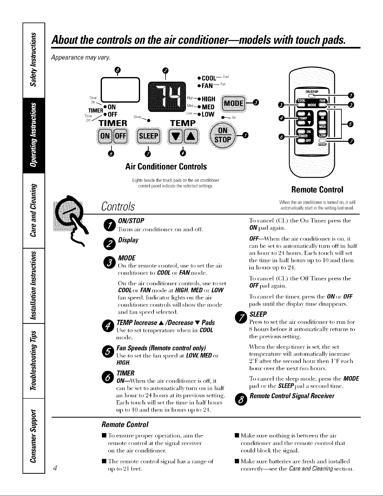
Aboutthecontrolsontheair conditioner--modelswith touchpads.
Appearance may vary.
• COOL-- c001
Time_ [
On._.
TIMER• ON
Tim_/ • OFF
off/TIMER
Air ConditionerControls
_J_ H_oh-•HIGH
ved_•MED
Low-• LOW ............................
TEMP
Lightsbesidetbetoucbpadsontheairconditioner
controlpanelindicatetheselectedsettings.
On
RemoteControl
Controls
O ON/ITOPo o
Turn,_ air c nditi net on and off.
Display
_1 MODE
VOn tile remote control, use to set tile air
conditioner to COOLor FANmode.
On tile air conditioner controls, use to set
COOLor FANInode at HIGH,MED or LOW
tim speed. Indicator lights on tile air
conditioner controls will show tile mode
and tan speed selected.
O TEMP Increase •/Decrease • Pads
Use to set temperature when in COOL
illode,
O an Speeds (Remote control only)
Use to set tile tim speed at LOW,MEDor
HIGH.
O TIMER
ONi\._q/en tile air conditioner is off, it
can be set to automatically turn on in half
an horn" to 24 horn's at its previous setting.
Each touch will set the time in half horns
up to l0 and then in horns up to 24.
Whentheairconditioneris turnedon,it will
automaticallystartinthesettinglast used.
To cancel (CI,) tile On Timer press tile
ONpad again.
OFF--_A]Ien tile air conditioner is on, it
can be set to automatically turn off in half
an hour to 94 horns. Each touch will set
tile time in half hom_ up to l 0 and then
in hom_ up to 24.
To cancel (CI,) the OffTimer press the
OEEpadagain.
To cancel tile time_; press tile ONor OFF
pads/mtil tile display time disappears.
O SLEEP
Press to set tile air conditioner to run for
S hom_ before it automatically returns to
the previous setting.
X&]mn the sleep timer is set, the set
temperature will automatically increase
2°F atter tile second hour then l °F each
hotlr over tile next two hotllS.
To cancel tile sleep mode, press tile MODE
pad or tile SLEEPpada second time.
O RemoteControlSignal Receiver
Remote Control
• To ensure proper operation, aim tile
remote control at tile signal receixer
on tile air conditioner
• Tile remote control si,mal has a range of
4
up t() 21 feet.
• Make sm'e nothing is between tile air
conditioner and tile remote control that
could block the signal.
• Make sm'e batteries are fl'esh and installed
con'ecflx_see tile Care and gleaning section.
Page 5
COOLMODE
ge.com
RemoteControl
l. Px_ss COOLpad.
2. Px_ss LOW. IVIEDor HIpads to set desired fire speed.
3. PI_SS the INCREASEA/DECREASEVpads to set the
desix_d temperature 60°F to 85°F in l °F increments.
ControlPanel
l. Pxess fl_e MODEpad until tile COOLindicator lig]lt is
lit and the LOW.MEDor Hlin(ficator light is lit tbr
die (lesix_(1t_m speed.
2. Px>ss the INCREASEA/DECRFAISET pads to set the
(Iesix_d temperature 60°F to 85°F in l °F increments.
A them_osmt is used to maint_fin the room
tempenmtre. Tile compressor will wcle on and off
to keep tile room at the set level of comtbrt. Set die
thermostat at a lower number and die indoor air will
Fan Switch
The tim switch is located behind the ti'()nt grille on the
control box. Access through a hole in control box.
_,_]mn set at CYCLE(do_n) the tbn e',cles on and ottl
FAN MODE
become coolex; Set tile thermostat at a higher nmnber
and the indoor air will become _mnex:
NOTE:ff theairconditionerisoffandisthenturnedon
whilesettoCOOL,it willtakeapproximately3minutesfor
thecompressortostartandcoolingtobegin.
CoolingDescriptions
ForNormalCooling--Select the COOLmode and
HIGHor MEDtim with a middle set temperature.
ForMaximum Cooling--Select tile COOLmode
and HIGHtim with a lower set tempemtm>.
ForQuieter& NighttimeCooling--Selectthe COOLmode
and LOWfimwidi a middle set temperature.
NOTE:If youswitchfromaCOOLsettingtoOFFor to
afansetting,waitatleast3minutesbeforeswitchingback
toaCOOLsetting.
When set at CONT(confimtous, tip) the tim runs all the
time providing a mi/x_ balanced mmperau/x_. The unit
is shipped in the CONrsetting.
Use the FANmode to provide _dr circulation and
filtering without cooling. Since fire only settings do not
provkle cooling, a temperature setting will not be
displa}ed.
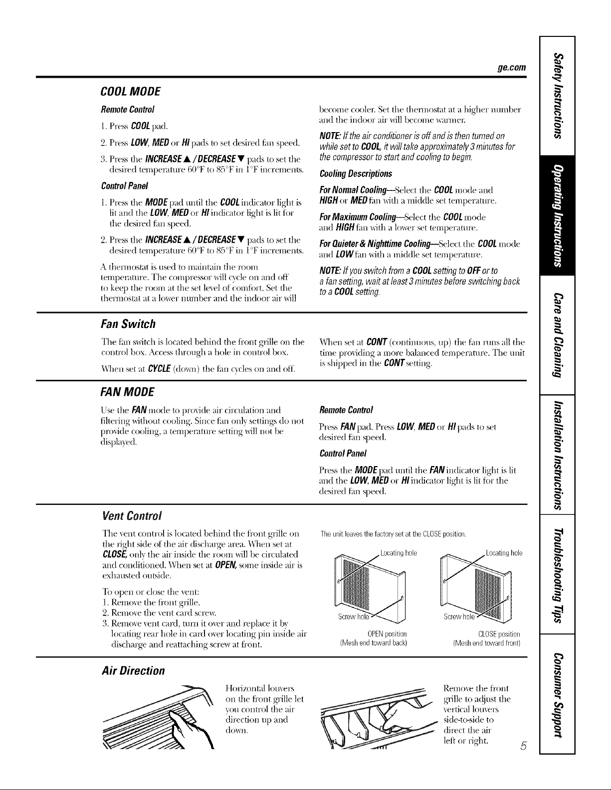
Vent Control
The vent control is located behind the ti'ont grille on
the right side of the air (fischarge area. "_\lmn set at
CLOSE,only tile air inside fl_e room will be circulated
and conditioned. When set at OPEN,some inside air is
exhausted outside.
To opeil or close tile vent:
1. Remove the ti'ont grille.
2. Remo\ e the vent card scx_.
3. Remove vent card, turn it over and replace it b}
locating rear hole in card over locating pin inside air
discharge and reattaching scre_ at fi'ont.
A# Direction
Hofizont_fl lomers
on fl_e Ii'ont grille let
you control the air
(lirection up and
douvI/.
RemoteControl
Px>ss FAN pad. Press LOW,MEDor HI pads to set
(lesix_(1 fire speed.
ControlPanel
Pxess die MODEpad until the FANindicator light is lit
and the LOW, MEDor HIin(ficator light is lit for the
(lesix_(1 f_mspeed.
Theunitleavesthefactoryset attheCLOSEposition.
._Locating hole
Screwhole "_.
OPENposition
(Meshendtowardback)
Screwho
CLOSEposition
(Meshendtowardfront)
Remove tile fi'ont
grille to a@/st the
vertical lou\'ers
side-to_ide to
dixect the air
left or fight.
Page 6
Aboutthe controlsontheair conditionermmodels with touchpads.
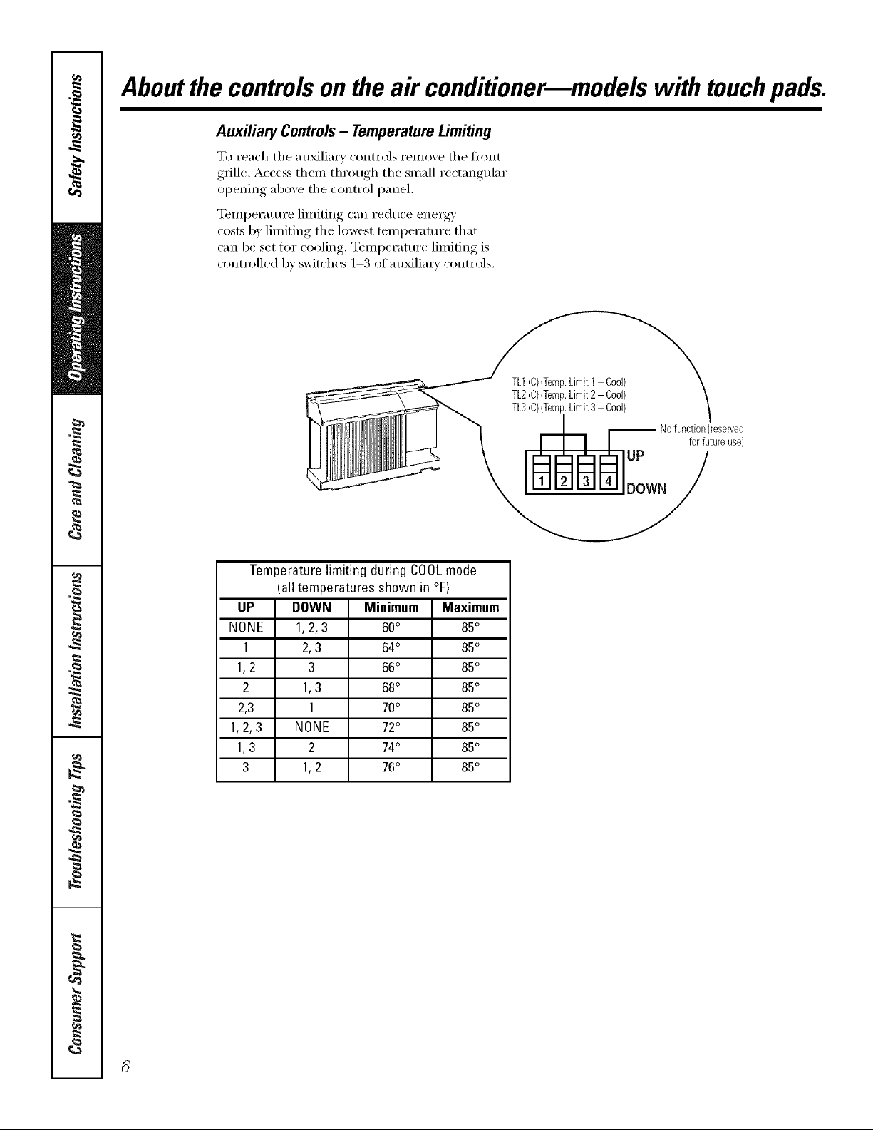
Auxiliary Controls- TemperatureLimiting
To reach the auxiliary controls remove the fl'ont
g_ille. Access them through the small rectangular
opening above the control panel.
Temperature limiting can reduce energy
costs b)' limiting the lowest temperattu'e that
can be set fin" cooling, Temperattu'e limiting is
controlled by switches 1-3 of au_lia_a' controls.
TL1(C){Temp.Limit1 Cool)
TL2(C){Temp.Limit2 Cool)
TL3(C/(Temp.Limit3 Cool/
-- Nofunctioll(reserved
UP
DOWN
for futureuse)
Temperaturelimiting during COOLmode
(all temperatures shown in °F)
UP DOWN Minimum Maximum
NONE 1, 2, 3 60° 85°
1 2,3 64° 85°
1,2 3 66° 85°
2 1,3 68° 85°
2,3 1 70° 85°
1,2,3 NONE 72° 85°
1,3 2 74° 85°
3 1,2 76° 85°
Page 7
Page 8
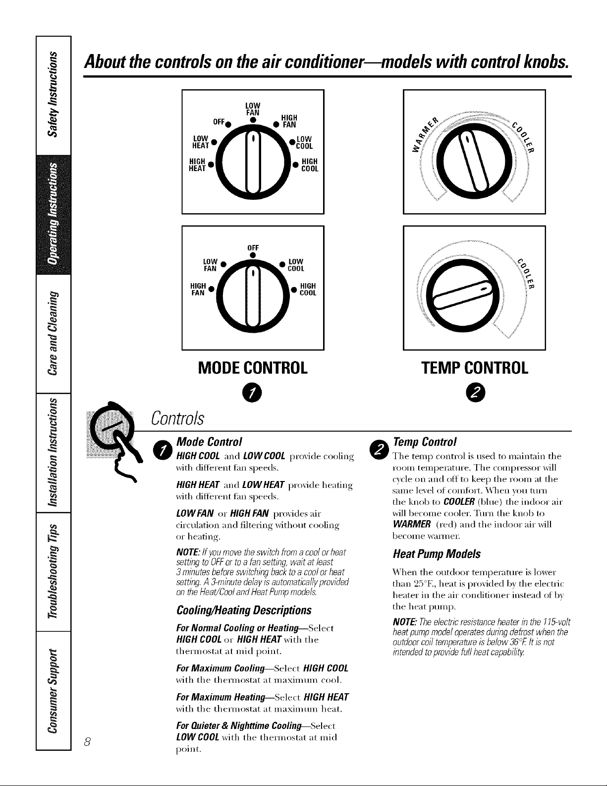
Aboutthecontrolsontheair conditioner--modelswith controlknobs.
LOW
OFF • HIGH
LOW_ _ I I I _ ALOW
FAN
rOI_j_I_ FAN
HEAT'II I yCOOL
HIGH_BB I I II_ HIGH
HEAT--_" COOL
OFF
LOWa _ a LOW
FAN_COOL
HIGHm • I I •_ HIGH
FAN w_w COOL
MODECONTROL TEMPCONTROL
o Mode Control
HIGHCOOLand LOWCOOLI)r°_ide cooling
with different tim speeds,
HIGHHEATand LOWHEATprovide heating
with different Lm speeds.
LOWFAN or HIGHFAN provides air
cir(-ulation and filtering without cooling
or heating.
NOTE:If youmovetheswitchfromacoolorheat
settingtoOFForto afansetting,waitat least
3 minutesbeforeswitchingbacktoa coolorheat
setting. A 3-minute delay is automat/cally provided
on the Heat/Cool and Heat Pumpmodels.
Cooling/Pleating Descriptions
ForNormal CoolingorHeating--Select
HIGHCOOLor HIGHHEATwifl_ the
thermostat at mid point.
ForMaximum Cooling--Select HIGHCOOL
with the thermostat at maximum cool,
S
0
o TempControl
The temp control is used to maintnin the
room temperatm'e. The compressor will
cycle on and off to kee I) the room at the
same level of comfiwt. _\]_en you tm'n
the knob to COOLER (blue) the indoor air
will become cooler, Tm'n the knob to
WARMER (red) and the indoor air will
become waxen eI;
Heat PumpModels
When the outdoor temperature is lower
than 25°F., heat is provided by the electric
heater in the air conditioner instead ot bv
the heat I)ump.
NOTE"Theelectricresistanceheaterinthe115-volt
heatpumpmodeloperatesduringdefrostwhenthe
outdoorcoiltemperatureisbelow38°£Itisnot
intendedtoprovidefullheatcapabilit_
/
For Maximum Heating_Select HIGH HEAT
with the thermostat at maximmn heat.
For Quieter & Nighttime Cooling--.Select
8
LOW COOL with the thermostat at mid
point,
Page 9

Fan Switch
To reach tile tim switch (es) remove tile
fl'ont grille.
OnHea_/Cooland Heat Pump models, tile tim switch
levex_ are located in holes accessed through tile
control box. Tile top switch is fin _COOL settings
and tile bottom sMtch is fin" HEATsetfings.
Use a small screwdriver to change the setting.
The trait is shipped fl'om the thctory set in the
CONTsetting tot COOLand in tile cgCtfsetting
fi)r HEAT
Coolonly models have a rocker switch on tile
front of the control box.
_,_]_en set at CYCLE(down) tile tim cycles on and
off when cooling. When set at CONT(continuous,
up) tile tim runs all tile time, providing a more
balanced mmperamre. Tile trait is shipped in
the CONTsetting.
Temperature Limiting
Limiting the maMmum and minimum settings
prevents use_ ti'om turning the control to the
extreme heat or cool positions.
ge.com
• •
® •
The n(mnal range of the temp control is
approximately 60°F to 85°E The control range
may be narrowed by the use of the temperatm'e
limiting screws located behind the control panel.
Vent Control
Tile vent control is located behind tile ti'ont
grille on the fight side of the air discharge area.
X_lell set at CLOSE,onl) the air inside the roonl
will be circulated and conditioned. When set at
OPEN,soine inside air is exhausted outside.
To open or close tile vent:
1. Remove the front grille.
2. Remove the vent card screw.
3. Remove vent card, mrn it over and replace
it by locating rear hole in card over locating
pin inside air discharge and reattaching
ScI'eW _lt [i'OIlt.
A# Direction
Horizontal h)m e_
(m tile fl'ont grille
let you control the
air di*ection up
and down.
®
Limits@ Limits
heat cool
temp temp
Eachposition equals approximately 3°E
Ti_eunitleavesthefactorysetatthe CLOSEposition.
_hole
Screwhc
OPENposition
(Meshendtowardhack)
(Meshendtowardfront)
Remox e tile fl'ont
grille to ac!iust tile
vexlical loux ers
side-to-side to
direct tile air left
(>r fi ,ht
CLOSEposition
9
Page 10

Careand cleaningof theair conditioner..
Grille and Case
Turn the air conditioner ott and remo_e the To clean, use water and a mild detergent.
plug, ti'()m the wall outlet before cleaning, Do not use bleach or abrasives.
OutdoorCoils
The coils on the outdoor side ()t the air
conditioner should be checked regularly.
If they are clogged with dirt or soot they may be
professionally steam cleaned, a service available
through your GE se_Mce outlet.
Front Grille
The ti'ont grille can be removed tot more
thorough cleaning or to make the model and
serial n/llllbeYs accessible.
Toremove:
1. Pull the filter out.
2. Remove the two grille scre_vs.
J
Onsomemodels
Onsomemodels
3 Pull the r,rille out fl'om the bottom and lift up
ti'om the tabs on the top of the case.
Grille
O_
Toreplace:
Hook the tabs on the ti'ont grille even with the
tabs on the case and snap into place.
Replace the scre_vs and filte_:
10
Page 11

Tomaintain optimum performance, clean the filter at least every30 days.
Air Filter
Toremove the a# filter, on uther models:
Pull it down.
go.corn
Dir:y filte_Needs cleaning Clogged filter Greatly
reduces cooling, heating
and airflow.
Turn the a# conditioner off before cleaning.
The most important thing you can do to
maintain the air conditioner is to clean the filter
at least every 30 days. A clogged filter reduces
cooling, heating and air flow.
Keeping the air filler clean will:
[] Decrease cost of operation.
[] Save energr} '.
[] Prevent clogged heat exchanger coils.
[] ]{educe the risk of l)remature coilll)onent
fifilm'e.
To clean the air filters:
[] Vacumn off the heavv soil.
[] ])-amwater through the filte_3.
[] D_T thoroughly betore replacing.
Toremove the air filter, on somemodels:
Careflflly pull the tab forward, up and out.
To replace the air filter."
Replace the clean filter by I)ushing it back
into place.
A
CAUTION:oonutoperatetheair
conditioner without the filter in place. If a filter
becomes torn or damaged it should be replaced
immediately.
Operating without the filter in place or with a
damaged filter will allow dirt and dtlst to reach
the indoor coil and reduce the cooling, heating,
ai_low and efficiency ot the trait.
How to Insert the Batteries
] Remove the battery cover b) sliding it
according to the arro_ direction.
] ]nsel_ ne_ batteries maldng sure that the
(+) and (-) of battel 3 are installed correctly.
] Reattach the co_er b) sliding it back
into position.
Replacement filtet_ are ax filable from yore',
salesl)e_on, (;E dealer, (;E Service and Pa_ts
Center or authorized Customer Care _ servicers.
NOTES:
[] Use 2 _ (1.5 volt) batteries. Do not use
rechargeable batteries.
[] Remo\ e the batteries fi'om the remote control
if the s}:stem is not going to be used tot a long
tim e.
//
Page 12

Installation
Air Conditioner
Instructions
I [] Questions? Call 800.GE.CARES (800.432.2737) or Visit our Website at: ge.com I
BEFORE YOU BEGIN
Read these instructions completely and
carefully.
• IMPORTANT - Savetheseinstructions
for local inspector's use.
• IMPORTANT - Observeallgoverning
codes and ordinances.
• Note to Installer - Be sure to leave these
instructions with the Consumer.
• Note to Consumer - Keep these instructions for
future reference.
° Skill level- Installation of this appliance requires
basic mechanical skills.
• Completion time - Approximately 1 hour
• We recommend that two people install this
product.
• Proper installation is the responsibility of the
installer.
• Product failure due to improper installation
is not covered under the Warranty.
Q ELECTRICAL REQUIREMENTS
Z CAUTION:
Do not, under any circumstances, cut or remove
the third (ground) prong from the power cord.
Do not change the plug on the power cord
of this air conditioner.
Aluminum house wiring may present special
problems--consult a qualified electrician.
IMPORTANT!
GE strongly recommends the removal of the old
wall case and the installation of a new GE Wall
Case. If you decide to keep the existing wall case,
you may need a kit to ensure proper performance.
If you DO NOT use a kit, you run the risk of poor
performance or product failure. This is not covered
under the terms of the GE warranty.
J-MODEL QUALIFYING QUESTIONS
J-model air conditioners may fit in existing wall cases.
However, they often need a kit to properly adapt the
case to the GE air conditioner. Answer these questions
and see the chart on the next page for the proper kit.
I-_ What brand air conditioner will you be replacing?
What are the dimensions of the wall case
[] currently in use?
60 Hz grounded outlet protected with a
Some models require a 115/120-vok a.c.,
15-amp time delay fuse or circuit breaker.
The 3-prong grounding plug minimizes the possibility
of electric shock hazard. If the wall outlet you plan to
use is only a 2-prong outlet, it is your responsibility
to have it replaced with a properly grounded 3-prong
wall outlet.
Some models require 230/208-volt a.c.,
protected with a time delay fuse or circuit
breaker. These models should be installed
on their own single branch circuit for best
performance and to prevent overloading
house or apartment wiring circuits, which
could cause a possible fire hazard from
overheating wires.
[] What isthe model number of the chassis
currently in use?What isthe model (or Type)
number of the wall case currently in use?
Frequently, the J-model adapter kit will apply to
another brand model "series" or specific vintage.
In these cases, you need the chassis model
number and/or the wall case or "type" number
to confirm the use of the correct adapter kit.
[] What type of outdoor grille isused with the
current wall case?
There may be an architectural grille attached to
a wall case to enhance the exterior appearance
of the building. Custom grilles may be used with
J-model wall cases provided a J-model adapter
kit is also used to ensure proper airflow.
12
Page 13

Installation instructions
Read these instructions completely and carefully.
Power cord may include a current interrupter
device. A test and reset button is provided on the
plug case. The device should be tested on a
periodic basis by first pressing the TEST button
and then the RESET button. If the TEST button
does not trip or if the RESET button will not stay
engaged, discontinue use of the air conditioner
and contact a qualified service technician.
TOOLS YOU MAY NEED
screwdriver
Phillips head _ __
Adjustable Wrench L_ Level
Drill _ Scissors or knife
r_/_ _-::,.= Hand or Saber Saw
Pencil _a{__t
Ruler or Tape
Measure
GE KIT NUMBERS
USE GE
KIT NUMBER: FOR: DESCRIPTION:
RAK56A100 GERAB13,14 & 15 Fitsall GEwall cases 26"W x 18"Hx 24"D
(ACLB& RCLChassis)
RAK1072 Hotpoint ACXB10& 11 Adapts an older Hotpoint wall caseto a "J"
(ACTBChassis) model chassis. Fits Hotpoint wall cases
253A"Wx 167X'Hx 18_"D
RAK1082 Whirlpool Type23W Adapts Whirlpool wall case to a "J"
Wall Case model chassis. Fits Whirlpool wall
cases257X'_/Vx 16W'H x 23W'D
RAK1102 GERAB30 Adapts GEwall caseto a "J" model chassis.
("F" models) Fitsthe RAB30 wall case26"W x 18"H x 24"D
RAK123A64 FeddersWall Case"A" Adapts Fedderswall caseto a "J" model chassis.
FitsFedderswall cases27"W x 16sA"Hx 16sA"D
RAK126 Westinghouse Wall Case Adapts Westinghouse wall caseto a "J"
(Type2626D73H01) model chassis. FitsWestinghouse wall
cases257X'W x 15746"Hx 16"D
RAB46, 47 & 48 Usethese kits for all Standard wall casefor "J" model chassis.
other brands not listed. RAG13stamped aluminum exterior grille
included. Removethe existing case
and replace.
RAK690 RAB36,37, 38, 46, 47 or 48 If you attach acustom architectural outdoor
(J-Chassis) grille, usethis kit to ensure proper airflow.
RAG13 RAB36,37, 38, 46, 47 or 48 Standard aluminum exterior grille (included with RAB46,47, and 48 wall
(J-Chassis) cases)
RAG14E RAB36,37, 38, 46, 47 or 48 Architectural Iouvered exterior grille
(J-Chassis)
13
Page 14

Installation Instructions
INSTALLING A J-MODEL IN AN EXISTING WALL CASE
Read these instructions completely and carefully.
[] REMOVE LOCKING PLATE ON
FRONT LEFT SIDE
Locking
plate
Remove
screw
[] REMOVE THREE SHIPPING PADS
INSIDE AIR CONDITIONER NEXT TO
COMPRESSOR
[] REINSTALL LOCKING PLATE WITH
TAB BEHIND WALL CASE FLANGE.
TIGHTEN SCREW
[] ATTACH POWER CORD TO BASE
PAN WITH CLAMP
pan
cord
P
[] WHEN WALL OUTLET IS TO LEFT,
EXTEND CORD UNDER UNIT AND
HOLD IT IN PLACE WITH CLAMP
[] CAREFULLY SLIDE AIR
CONDITIONER BACK INTO CASE
Make sure that the tubing on the unit does
not touch the wall case and that the case
installation is secure.
Remove
shipping
pads
Power
p cord
[] ATTACH FRONT GRILLE
An opening for the power cord is on the
bottom of the front grille.
Page 15

Installation instructions
INSTALLING THROUGH THE WALL
Read these instructions completely and carefully.
[] PREPARE OPENING IN WALL
Make certain a wall receptacle is
available close to the hole location or make
arrangements to install a receptacle.
The cord length for the 115-volt models is 72"
to the right and 47" to the left.
For the 230/208-volt models the cord length is
65" to the right and 39" to the left.
[] SUPPORT REQUIREMENTS FOR
AIR CONDITIONER
The air conditioner wall case may be installed
with 1/4" min. extension out from the inside
wall or with 1/4" min. extension out from the
outside wall.
The finished sides of the opening should be
structural wall members.
Lintel - Use a lintel in brick veneer and brick
and block types of wall to support the bricks
or blocks above the opening. Do not allow the
wall case to be used in lieu of a lintel.
Flashing - Install flashing (drip rail) as shown
to prevent water from dripping inside the wall
and down the outside of the building.
Brick
Lintel angle
(if required) _ Plaster
Caulking _ line
(on all 4_
sides on the Trim
outside of molding
the case) (if desired)
[] SUPPORT REQUIREMENTS FOR
AIR CONDITIONER
Mortar between the case and the brick all
around the case may be undercut at about 45°
for improved caulking.
Inside
Top of case
Outside
_ Undercut
Caulking
mortar
Flashing
(drip rail)
Room side
f
1/4" min. extension
inside the wall from
the trim molding
15
Page 16

Installation instructions
WINDOW INSTALLATION--OPTIONAL
FOR MODELS AJES06LSB, AJES08ASB, AJES10DSB and AJHS08ASB
Read these instructions completely and carefully.
F inyl window
gasket
Sill support
bracket (2) X_k
2 angles----_-
(left and
right hand)
Case side
gasket (2)
Foam top
_' _ window gasket
• B
Right
side
03
03
03
03
lr
Type A (9)
I A •
I
'_Left side
Filler _"
Panels
Cut panels c_
and _ "
discard o
center _-
piece
I i •
L J
B I
i
_'-- SlPri_4_ \ Case top gasket
Type C (painted) (6)
P _ Bottom window gasket
Air conditioner
Type D (2)
Type E (4)
Window
bracket
_ locking
Support bracket hardware
4'
Spacer 12)
Lock nut (2)
$
Adjusting bolt (2)
Type B (2)
[] WINDOW REQUIREMENTS
• These instructions are for a standard double-hung
window. You will need to modify them for other
types of windows.
• The air conditioner can be installed without the
accordion panels if needed to fit in a narrow
window. See the window opening dimensions
to the right.
• All supporting parts must be secured to firm wood,
masonry or metal.
• The electrical outlet must be within reach of the
power cord,
Large washer (2)
L ]
[Y===8
17" min.
31" to 43"
(With filler panels)
261/4"min.
(Without filler panels)
Window opening dimensions are for a
standard double-hung window.
16
Page 17

Installation Instructions
[]STORM WINDOW REQUIREMENTS
A storm window frame will not allow the air
conditioner to tilt towards the outside and will
keep it from draining properly. To adjust for this,
attach a piece of wood to the stool.
1/2"higher _ ,_/- Wood
than A
frome
Storm" I] II
window /I II
frame /_ I[
r_REMOVE AIR CONDITIONER FROM CASE
[] Remove the front grille. See the Care and
Cleaning section,
[] Find the locking plate located on the front
left side,
[] Remove the screw and the locking plate to
unlock the air conditioner.
WOOD PIECES:
WIDTH: 2"
LENGTH: Long enough to fit inside the window
frame.
THICKNESS: To determine the thickness, place a
piece of wood on the stool to make it 1/2" higher
than the top of the storm window frame.
Attach securely with nails or screws provided by
the installer.
[] Remove the three shipping pads inside the air
conditioner next to the compressor.
Locking
plate
screw
[]
Remove and discard the shipping screw
on the back of the air conditioner to allow
removal of the air conditioner from the
case.
Remove
screw
Remove
shipping
pads
[] Remove the rear grille that is taped to the back
of the case. Remove the packet of screws taped
to the back of the grille. While holding the grille
at a 45° angle, insert it into the clips at the top of
the case and push the bottom in. Keep slight
upward pressure on the grille until it fits flush
with the bottom of the case.
If attaching the grille
from the outside of
the case use the 2
long screws.
Clips
If attaching the grille
on the inside of the
case use the 2 short
screws.
I 1111111111111111111111111111111111111111111111I,
llllllllllllllllllllllllllllllllllllllllllllltJl
/11111111111111111111111111111111111111111111!H
[]
Pull the bottom corners of the air
conditioner and slide it out of the case.
Insert the 2 long screws on
the outside
17
Insert the 2 short screws
on the inside
Page 18

Installation instructions
WINDOW INSTALLATION--OPTIONAL (cont.)
[] PREPAREWINDOW
[] Mark the centerline of the stool, Measure
from the centerline 13%" on both sides for
the panel cuts.
[] Measure 12%" from the centerline on both sides
for the sill support brackets.
Centerline
_-_ 13%" -_
Sill
[] INSTALL SILL SUPPORTS
[] Assemble the sill supports. Do not fully
tighten the spacer mounting screws at this
time.
Type B
Type E
Spacer mounting
screws Type (A)
support
Centerline
1
[] Turn the bolts and tighten the lock nuts to make
the sill supports level or tilt down 1/8" to the
outside. Line up the "V" notch with 12%" marks.
Drill pilot holes and attach the sill supports.
Average sill
/_ Spacer
Sill support
Narrow sill
Adjusting bolt -_
Large washer_
(For use with wood
sills)
[] Before attaching the sill supports, place
them on the window stool. Select the spacer
position that will place the spacer near the
outermost point on the sill. Tighten the
spacer mounting screws.
Screws are in position
Sill
support
"V" notch
Offset sill (such as brick or stone)
NOTES:
• On narrow sills, there may not be enough room to
use the lock nut.
• A deep offset sill may require a longer adjusting
bolt than the standard hex head bolt provided.
• On wood sills use the large washer between the
bolt head and the sill. This prevents the bolt from
digging into the wood.
18
Page 19

Installation instructions
[] MEASURE, CUT AND INSTALL
FILLER PANELS
[] Measure from the edge of the panel marks
(see Prepare the Window) to the inside of
the window track on each side. (A and B)
Sill
/ Wind°w track_,_k
Gasket-_ _j¢/_ Angle
Angle
Gasket___anel
Type C
(painted
screws)
4, _-_'/- 13%" i 133X" ":"" ___
' A '_'_ Width ofthe air "_'_ B _
Left side (panel marks) Right side
[] Mark the A and B measurements on each
side of the filler panel board. Cut the panels
and discard the center piece. Note position
of the notches.
[] Put together the panel assemblies. Remove
the paper backing from the case side gasket
and attach it to the angle. Push a pencil point
through the gaskets to locate the holes in
the angles.
conditioner
• B A =
Right Left
side side
--_ Filler
Panels _ •
= Cut
o panels o
,_ and =
discard -_
--_ center _..
o _, piece , _ •
a u v
Tab._/4
[] Install the panels in the window. Place the spring
clips 3" from the top and the bottom. Squeeze
and push the clips to fit in the window track and
the tab into the sill support.
l
Hook the tab into
the sill support
19
Page 20

Installation Instructions
WINDOW INSTALLATION--OPTIONAL (cont.)
[] INSTALL CASE IN WINDOW
[] Peel off the backing from the bottom
window gasket.
[] Place the gasket on the stool and over the
brackets, even with the rear edge, sticky
side down.
L J
Bottom window gasket
[] Carefully slide the empty case into the
window until the holes in the case line up
with the holes in the panel angles.
Case holes
[] With the window closed, mark where the
window sash meets the case.
[] Peel offthe backing from the case top gasket.
[] Hold on to the case, open the window, and
place the gasket along the mark on the case.
Put the gasket
on top of the
case where
the window
will close.
[] Place the vinyl window gasket over the case top
gasket. Insert the panel tabs through the slits in
the gasket. Cut the gasket on each side to the
width of the window.
NOTES:
• The case should have a 1/8" minimum tilt
toward the outside.
• Be sure the seal gasket and panel gaskets
remain in position and do not roll with the
case.
[] Lower the window so it fits behind the panel
tabs. Insert the 4 type A screws through the
holes in the case and into the panel angles,
2 on each side.
ta bs
Case
screws
tab
_ndow
[]
Close the window tightly on the vinyl gasket.
Bend the gasket forward to expose the panel
tabs. Drill pilot holes into the window sash,
_Attach the panel tab
to the window on
each side with a type
D screw.
2O
Page 21

Installation instructions
[] INSTALL WINDOW GASKET AND
LOCKING BRACKET
[] Cut the foam top window gasket to the
window width.
[] Stuff the foam between the glass and the
window to prevent air and insects from
getting into the room.
[] REPLACE AIR CONDITIONER IN
CASE
[] Carefully slide the air conditioner back into
the case.
[] Attach the window locking bracket with 1 type E
screw.
I
[] When the wall outlet is to the left, extend the
cord under the unit and hold it in place with the
clamp.
[] Attach the power cord to the base pan with
the clamp.
pan
Power cord
P
[] Reinstall the locking plate with the tab behind
the wall case flange. Tighten the screw.
_1 Y \1 _'_1t_/
•s hten
Loc_i_g _ __
Reattach the front grille. An opening for the
[]
power cord is on the bottom of the front grille.
Fill holes and cracks with caulking provided by
[]
the installer.
21
Page 22

Before youcall forservice...
Troubleshooting -tips:Save time and money! Review the chart below first and you may not need to call for service.
PossibleCauses WhatToDo
Airconditioner
doesnotstart
Airconditionerdoes Airflow is restricted. • Make sure there are no curtains, blinds or tim/iture
notcoolas#should bh)cking the fi'ont of the air conditionel:
The air conditioner
is unplugged.
The fuse is bloom/circuit • (_heck tile house filse/circuit breaker box mid
breaker is tripped, replace the fuse or reset tile breaker.
Power failure. • If power thilure occttrs, turn the air conditioner
• Make sure tile air conditioner plug ispushed
completel} into tile outlet.
OFF.V_hel/power is restored, \vail 3 minutes to
restart tile air conditioner to prevent tripping (,t
the COl//})ressof oxerload.
The current interrupter • Press the RESErbutton located on the po\_er cord plug.
device is tripped. • If the RESETbutton \dll not .stay.eng;_,g>ed,.... discontinue use
of tile air conditioner and contact a qualified selaice
technician.
The temp control may • On models \dth touch pads: In COOLmode, press tile
not be set correctly. DECREASETpad.
• On models \dth comrol knobs, tttrn tile temperature
knob to a higher number.
The air f'dter is dirty. * Cle;m the filter at least e_erv 30 days.
See the OporotiwInstructiotissecti()ll.
The room may have been hot. • _'_]/en tile air conditioner is first turned on, }ou need
Cold air is escaping. • Check for oI3ell film;ice registers,, and cokl air returns.
Coolhlg coils have iced up. • See "Air conditioner freezing up" belo\v.
to allo\_ time for the roO1Tl tO CO01 do\\l/.
• Set the air conditioner's vent to the closed position.
Airconditioner Ice blocks the airflow • On models \dth comrol knobs, set the mode control
freezingup mid stops the air conditioner at HIGHFANor HIGHCOOLwith the temp at WARMER.
from cooling the room. • ()n models \dth touch pads, set the controls at HIGH FAN or
HIGHCOOLandset the thermostat to a higher temperature.
Theremotecontrolis The batteries are inserted • Check tile p(,sition of the batteries. Thin should be
not working incorrectly, inserted correctly.
The batteries may be dead. • Replace the batteries.
Waterdripsoutside Hot, humid weather. • This is hernial.
Waterdrips indoors The air conditioner is not • For proper "_\ater disposal, make sure tile air con(litioner
tilted to the outside, slants slightly fi'orrl tile case ti'ont to tile real'.
Watercollectsin Moisture removed from air • This is .oma;fl for a short period ill areas \_ith little
basepan and drains into base pan. humidity; normal tot a longer period in _erv humid areas.
Normal Operating Sounds
• V_ter x_illcollect in tile base )an (turin > hioh
humidit_ or (m rainy days. The water may overflow
and drip from tile outdoor side of the trait.
• Tile fan may run exen when the compressor
does llot.
22
• Y)u rnm Ileal" a pinging noise caused b} \_ter being
picked ilI) and thro\_/ag_dnst the condenser on
rainy &its or when the humidit_ is higJl. This
design teatnre helps remove moisture and
improve etticiency.
• _bu rna_ hear the tlmnnostat click when the
compressor cycles on and off"
Page 23

Air ConditionerWarranty.
Aft warranty service provided by our Factory Service Centers,
or an authorized Customer Care®technician. Toschedule
service, on-line, 24 hours a day, vis# us at ge.com, or carl
800.GE.CARES (800.432.2737).For service in Canada, call
1.800.361.3400.Please have serial number and model number
available when calling for service.
GEWill Replace:
Anypart of the air conditioner which thils due to a defect in matei_als or workmanship,
Fromthedateof the
originalpurchase
FiveYears
Fromthedateof the
origina/purchase
Dudng this limited one-year warranty, GE will also pro_i(le, free of charge, all labor
and related service to replace the defecti',e part,
Any part ofthe sealed refrigerating system (the compressox; condensei; evaporator
and all connecting tubing) which tifils due to a defect in materials or workmanship,
Dudng this four-year limited additional warranty, GE will also i)rovi(le, free of charge, all
labor and related seI_'ice to replace the (lefecti\'e part,
!!!
::Ji::Service trips to your home to teach you how to use
the product.
_: hnproper installation, delivery or maintenance. If you
have an installation problem, or if the air conditioner is
of hnproper cooling capacity for the intended use,
contact your dealer or installer. You axe responsible for
providing adequate electrical comaecthlg facilities.
::Ji::Failure of the product restflting from modifications to
the product or due to mlreasonable use including
failure to provide reasonable and necessary
mahltenmlce.
!i?:In commercial locations labor necessary to move the
unit to a location where it is accessible for service by
an individual technician.
Staple your receipt here.
Proofof the original purchase
date is needed to obtain service
under the warrantz
iJi::Replacement of house fuses or resetting of circuit
breakers.
_: Failure due to corrosion on models not corrosion-
protected.
::Ji::Dmnage to the product caused by hnproper power
supply voltage, accident, fire, floods or acts of God.
_: IncidentaJ or consequential dmnage caused by possible
defects with this air conditioner.
iJi::Dmnage caused after delivery.
!i_:Product not accessible to provide required service.
Warranty. Any implied warranties, including the implied warrauties of merchautability or fitness for aparticular purpose,
EXCLUSIONOFIMPLIED WARRANTIES--Your sole aud exclusive remedy isproduct repair as provided hi this Lim#ed
are limited to one year or the shortestperiod allowed by law.
This warranty is extended to the original purchaser and any succeeding owner for products purchased for
home use within the USA and Canada. If the product is located in an area where service by a GEAuthorized
Servicer is not available, you may be responsible for a trip charge or you may be required to bring the product
to an Authorized GE Service location for service. In Alaska, the warranty excludes the cost of shipping or
service cats to your home.
Some states do not aflow the exclusion or limitation of incidental or consequential damages. This warranty
gives you specific legal rights, and you may also have other rights which vary from state to state. To know
what your legal rights are, consult your local or state consumer affairs office or your state's Attorney General
Warranter:General Electric CompanF.Louisville,KY40225
23
Page 24

ConsumerSupport.
Have a question or need assistanre _dth )ore" appliance? Tr} the (;E Appliances _v\ebsite 24 hom_ a day,
q
"I gEAppliancesWebsite go.corn
am da_ of the }ear! For greater convenience and thster service, you can now download Ox_ner's Mammls,
j order parts, catalogs, or even schedule service on-line. Y)u can also "_sk Ore" Team of Experts ......
}o[ir (l[lestiollS, alld st} Ill{loll I/lore...
ScheduleService
Expe_ (;E repair service is onl) one step awe} h'om xotn" doo_: (;et on-line and schedule xotsr service at
}our convenience 24 hem's any de) of the year! (-)r call 800.GE.CARES (800.432.2737) dining mmnal
business horn's.
go.corn
RealLifeDesignStudio oe.com
GE suppoi_s the lJni_w_al Design concept--products, services and em'iromnents that can be used by
people oi all ages, sizes and capabilities. _'W recognize the need to design ibr a wide range of physical and
mental abilities and impaim_ents. For details of GE's ljnives_al Design applications, including kitchen
design ideas ibr people with disabilities, check out ore" Website today. For the hearing impaired, please call
800.TDD.GEAC (800.833.4322).
ExtendedWarranties oe.com
Pro'chase a (;E extended warrant} and learn about special discounts that are available while xour, warren b
is still in effect. YOu can pro'chase it on-line an}time, or call S .626.2224 dining mmnal business hom_.
(;E Consumer Home Services will still be there after }our warrant} expires.
PartsandAccessories
00 _ " __
go.corn
Individuals qualified to seix'ice their own appliances can have parts 05"accessories sent directly to their
homes (VISA, Master( aid and Discover cards are accepted), Order on-line today, 24 hom_ eves)' day 05"
by phone at 800.626.2002 during nomml business hom_.
Instructions contained in this manual cover procedures to be performed by any user. Other servicing generally
should fie referred to qualified service personnel. Caution must he exercised, since improper servicing may cause
unsafe operation.
ContactUs
If you are not satisfied with the service you receive fl'om GE, contact us on our Website with all the details
including your phone numbel; or write to: Oeneral Managel; Customer Relations
GE Appliances, Appliance Park
I_ouisville, KY 40225
Register your new appliance on-line--at your convenience! Timel} prodtlct registration xdll allow for
l RegisterYourAppliance
enhanced commmfication and prompt service m*der the temps of)our _arranty, should the need arise.
YOu me} also mail in the pre-pfinted registration card included in the l)acldng, material.
go.corn
go.corn
Printed in China
 Loading...