

GE AJES06LSM1, AJCQ06LCBM1 Owner’s Manual
©
www.GEApp/iances.com
Coo[ O_d) :
Safety Instructions ......... 2, 3
Operating Instructions
Controls_Control I{a]obs .... 8, 9
Controls---Touch Pads ....... 4-6
Care and Cleaning
Air Filter ................... ] ]
Front Grille ................. 10
Grille and Case .............. 10
Outdoor Coils ............... l 0
Installation Instructions
Before You Begin .......... 19, 13
Installing a .[-Model in
an Existing _4'all Case ......... 14
Through-the-_'all
Installation--Optional ........ 15
Window Installation--
Optional on models
so equipped .............. 16-91
Troubleshooting Tips ........ 92
Nomml Operating Sounds .... 92
Consumer Support
Consumer Support ... Back Co_er
_A'anantv ................... 93
H_a_ P_mp:
Espahol
For a Spanish version of this manual, visit
our VVebsite at _vw.GEAppliances.com.
Para consuhar una version en espaflol de
este manual de instrucciones, visim nuestro
sido de internet www.GEAppliances.com.
Fran_aise
For a French version of this manual, visit
our _:ebsite at w_w.GEAppliances.com.
Pour une version flangaise de ce manuel
d'utilisation, veuillez visitor notre site web
l'adresse www.GEAppliances.com.
Write the model andserial
numbers here:
Model #
Serial #
Fim_dthese mmJ)ers om_a label on
the {ixm t o{ th e base [m N_behim_ d
the t_'ont g_i]]e.
TINSEA380JBRZ 49-7512 07-05 Jfl
IMPORTANTSAFETYINFORMATION.
READALLINSTRUCTIONSBEFOREUSING.
WARNING'!
For your safe_ the information in this manual must be followed to minimize the risk of fire, electric
shock or personal injury.
SAFETYPRECAUTIONS
Use this appliance only %r its intended
pml)ose as described in this Owner's
Manua].
iiiiiiiiiiii_iii
This air conditioner must be properly
installed in accordance with the
Installation Instructions before it is used.
iiiiiiiiiiii_iii
Ne_er unplug your air conditioner by
pulling on tim power cord. Always glip
plug firefly and pull straight out fiom the
receptacle.
iiiiiiiiiiii_iii
Repair or replace immediately all elecuic
service cords that haxe become fiwed or
otherwise damaged. Do not use a cord
that shows cracks or abrasion damage
along its length or at either the plug or
connector end.
Turn the mode control OR=and unplug
your air conditioner before making any
repairs or cleaning.
NOTE:Westronglyrecommendthat anyservicing
beperformedbya qualifiedindividual.
For your safety...do not store or use
combustible materials, gasoline or oflmr
flammable vapors or liquids in the vicinity
of this or any other appliance.
All air conditioners contain refi-igerants,
which under federal law must be remoxed
prior to product disposal. If you are getting
rid of an old product with refcigerants,
check with the company handling disposal
about what to do.
HOWTOCONNECTELECTRICITY
Do not, under any circumstances, cut or remove
the third (ground) prong from the power cord.
For personal safety, this appliance must be
properly grounded.
The power cord of this appliance is equipped
with a 3-prong (grounding) plug which
mates with a standard 3-prong (grounding)
wall outlet m minimize rite possibility of
electric shock hazard from dlis appliance.
Power cord may include a cmxent
intemq)ter device. A test and reset button is
provided on the plug case. The device should
be tested on a periodic basis by first pressing
the TESTbutton and then the RESErbutton.
If the rESTb, tto, does not trip or if the
RESt'button will not stay engaged,
discontinue use of the air conditioner
and contact a qualified service technician.
Haxe the wall outlet and circuit checked
by a qualified electrician to make sure the
outlet is properly grounded.
'_&'herea 9-prong wall outlet is encountered,
it is your personal responsibility and
obligation to haxe it replaced with a properly
grounded 3-piong wall outlet.
The air conditioner shou]d alwws be plug\g_d
into its own individual electrica] outlet which
has a x_ltag> rating flint matches file rating
plate.
This provides the best perfommnce and also
prevents oxerloading house wiring circuits
which could cause a fire hazard from
oxerheated x_,ires.
See the Installation Instructions, Electrical
Requirements section for specific electrical
connection requirements.
2
WARNING!
USEOFEXTENSIONCORDS--115-Voltmodelsonly
www.GEAppliances.com
Because of potential safety hazards under
certain conditions, we strongly recommend
against the use of an extension cord.
Howe_; ifvo/l Ill/lSt use all extension cord,
it is absolutely necessal T that it be a UL-listed,
14 gauge, 3-wire grounding type appliance
extension cord having a grounding type plug
and outlet and that file electrical radng of
the cord be 15 amperes (minimum) and
125 x_lts.
CAUtiON:
DONOT use an extension cord with any of the
230/208 volt models.
USEOFADAPTERPLUGS--115-Voltmodelsonly
Because of potential safety hazards under
certain conditions, we strongly recommend
against the use of an adapter plug.
Howex>i; if you must use an adaptei; where
local codes permit, a temporary connection
may be made m a properly grounded
9-prong wall outlet by use of a UiAismd
adaptor available at most local hardware
stores.
The larger slot in file adaptor must be
aligned with the larger slot in die wall
outlet m provide proper polarity in the
connec6on of the power cord.
When disconnecting die power cord fiom
the adapter; always hold the adaptor in place
with one hand while pulling the power cord
plug with the other hand. If this is not done,
the adapter ground te_ninal is x>tT likely to
break with repeated use.
If the adapter ground temfinal breaks,
DONOTUSEthe air conditioner until a
proper gTound has been established.
Attachingtheadaptergroundtermbal to a waft
outlet coverscrewdoesnotgroundtheappliance
unlessthecoverscrewis metal, not lesulated,and
thewaftoutlet is groundedthrough the housewiring.
Youshouldhavethe circuit checkedbya qualified
electriciantomakesuretheoutlet isproperly
grounded.
READANDFOLLOWTHISSAFETYINFORMATIONCAREFULLY.
SAVETHESEINSTRUCtiONS
3
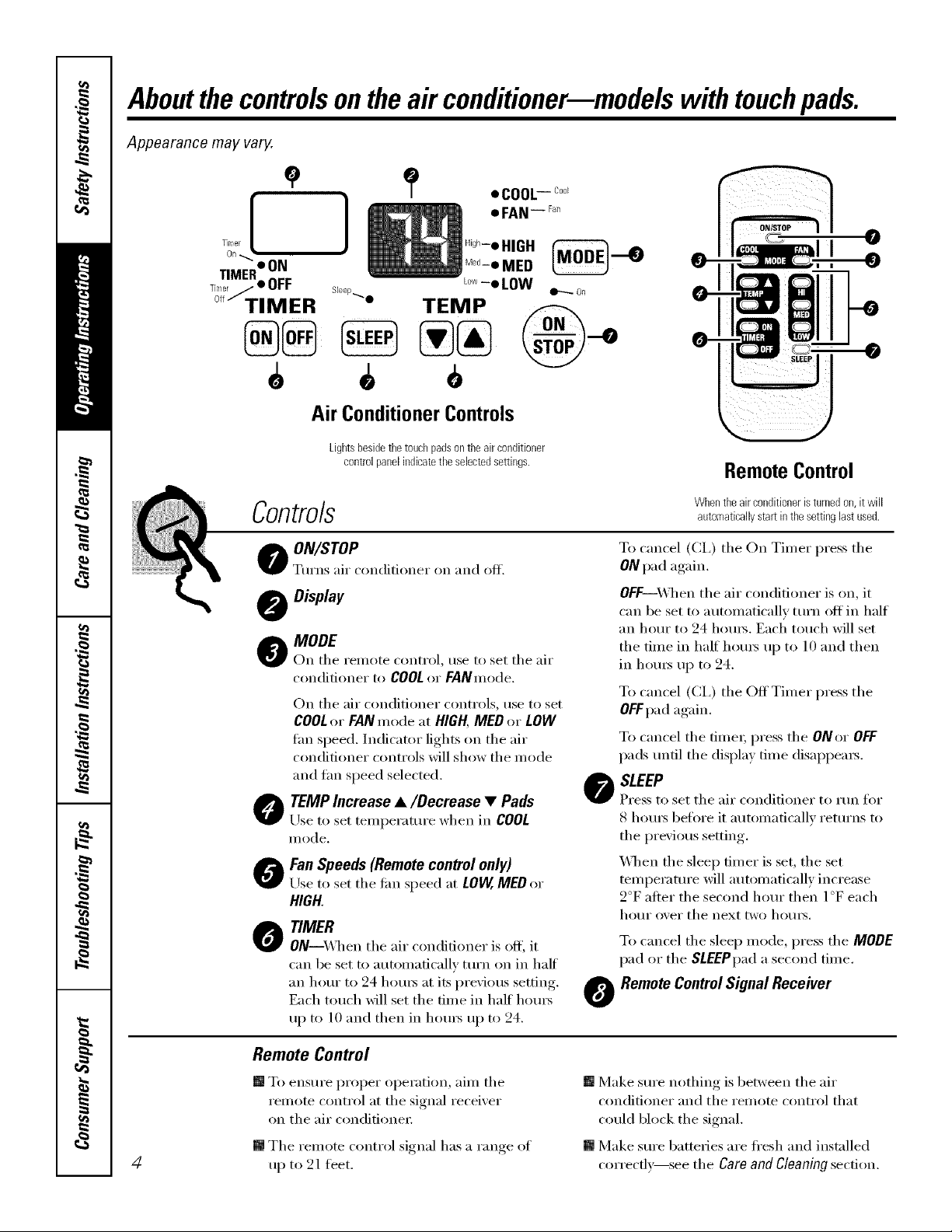
Aboutthecontrolsontheair conditioner--modelswith touchpads.
Appearance may vary.
]
Air ConditionerControls
Lightsbesidethe touchpadsontheairconditioner
controlpanelindicatetheselectedsettings.
RemoteControl
Controls
O ON/ITOPo o
Turn,_ air c nditi net on and off.
Display
_k MODE
r On tile remote control, rise to set tile air
conditioner to COOL or FANmode.
On tile air conditioner controls, use to set
COOLor FANmode at HIGH,MED or LOW
tim speed. Indicator lights on tile air
conditioner controls will show tile mode
and tan speed selected.
O TEMPIncrease •/Decrease • Pads
Use to set temperature when in COOL
illode,
O an Speeds (Remote control only)
Use to set tile tim speed at LOW,MEDor
HIGH.
O TIMER
ON--\._q/en tile air conditioner is off, it
can be set to automatically mrn on in half
an horn" to 24 hours at its previous setting.
Each touch will set the time in half horns
up to l0 and then in horns up to 24.
Whentheairconditioneristurnedon,itwill
automaticallystartin thesettinglastused.
To cancel (CI,) tile On Timer press tile
ONpad again.
OFF--_A]mn tile air conditioner is on, it
can be set to automatically tm'n off in half
an hour t() 94 h()ms. Each touch will set
tile time in half hom_ up to l 0 and then
in hom_ up to 24.
To cancel (CI,) the OffTimer press the
OEEpadagain.
To cancel tile time_; press tile ONor OFF
pads/mtil tile display time disappears.
O SLEEP
Press to set tile air conditioner to run for
S hom_ before it automatically returns to
the previous setting.
X&]mn the sleep timer is set, the set
temperature will automatically increase
2°F atter tile second horn" then l °F each
hour over tile next two hotllS.
To cancel tile sleep mode, press tile MODE
pad or tile SLEEPpada second time.
O RemoteControlSignal Receiver
Remote Control
[] To ensure proper operation, aim tile
remote control at tile signal receixer
on tile air conditioner
[] Tile remote control si_mal has a range of
4
up t() 21 feet.
[] Make sm'e nothing is between tile air
conditioner and tile remote control that
could block the signal.
[] Make sure batteries are fl'esh and installed
con'ecflx_see tile Care and gleaning section.
COOLMODE
wnnN.GEAppliances.com
RemoteControl
l. Px_ssCOOLpad.
2.P*_ssLOW.MEDor HIpads to set desired fire speed.
3.Px_ssdieINCREASEA/DECREASETpadsto set the
desix_d temperature 60°Fto 85°F ill l °Fincrements.
ControlPanel
l. Pless die MODEpad until tile COOLindicator lig]lt is
lit and the LOW.MEDor Hlin(ficator light is lit for
dm desil_d t_m speed.
2. Pl_ss the INCREASE&/DECREASET pads to set the
desil_d temperature 60°F to 85°F ill l °F increments.
A them/osmt is used to maintain tile roon/
tempenmlre. Tile con/pressor will (3cle on and off
to keep tile room at tile set level of comfi)rt. Set file
thermostat at a lo_r number and tim indoor air will
Fan Switch
Tile tim switch is located behind tile ti'ont grille on the
control box. Access through a hole ill control box.
_A]mn set at CYCLE((]o_n) tile thn e_cles on and oti_
FAN MODE
become coolel; Set tile thermostat at a higJmr nm-nber
and tile indoor air will become _mnel:
NOTE:ff theair conditioneris off andis thenturned on
while set toCOOL,it will takeapproximately3minutes for
the compressortostart andcooling tobegin.
CoolingDescriptions
ForNormalCooling--Select the COOLmode and
HIGHor MEDtim with a middle set temperature.
ForMaximumCooling--Select tile COOLmode
and HIGHfire with a lower set temperaU/l>.
ForQuieter&NighttimeCoolino--Select tile COOLmode
and LOWfimwifl_a middle set temperature.
NOTE:If youswitchfroma COOLsettingtoOFFor to
afansetting,waitatleast3minutesbeforeswitchingback
toaCOOLsetting.
When set at CONT(continuous, up) tile tim runs all tile
time providing a mol_ balanced mmperaull_. The unit
is shipped ill the cONrsetting.
Use tile FANmode to pro\ide _drcirculation and
filtering without cooling. Since fire only settings do not
provide cooling, a temt)emture setting will not be
displa}ed.
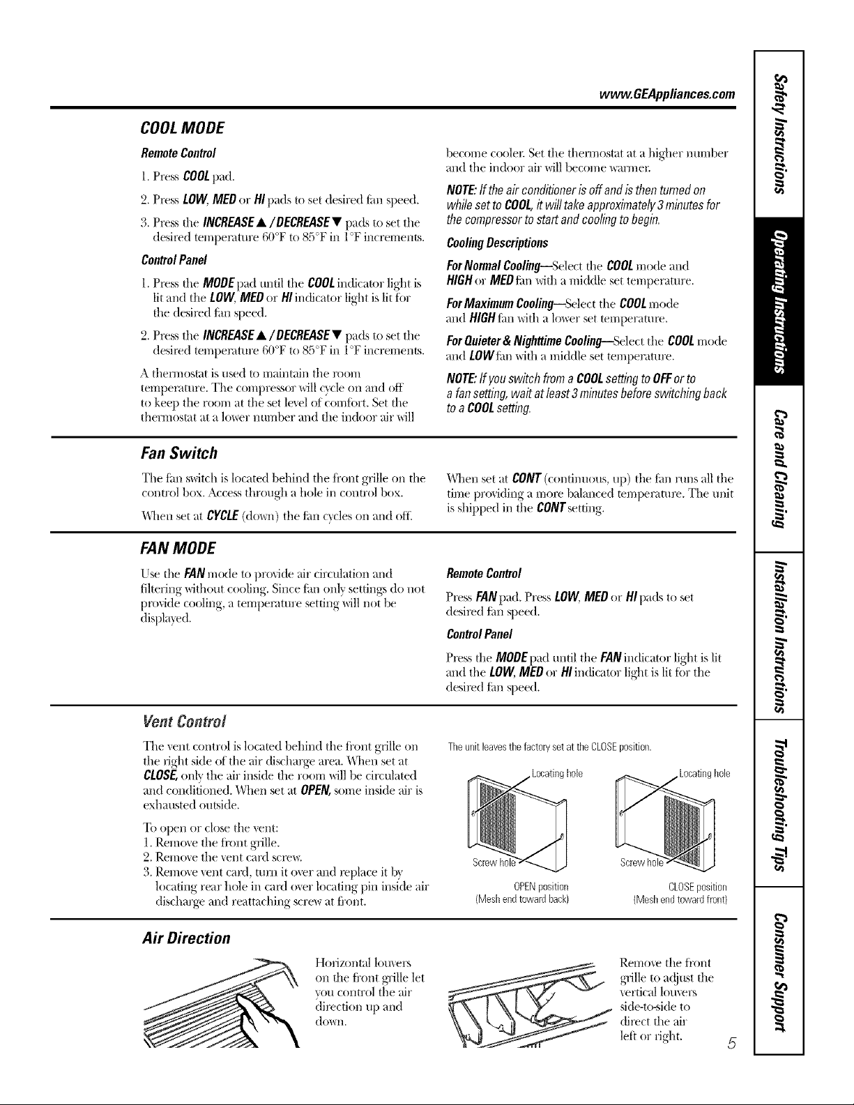
Vent Control
Tile vent control is located behind tile ti'ont grille on
tile right side of tile air (fischarge area. "_lmn set at
CLOSE,only tile air inside file room will be circulated
and conditioned. When set at OPEN, some inside air is
exhausted outside.
To opell or close tile vent:
1. Remove the ti'ont grille.
2. Remove tile vent card scions.
3. Remove vent card, turn it o\'er and replace it b}
locating rear hole ill card over locating pin inside air
discharge and reattaching scre_ at fi'ont.
A# Direction
Horiz(mt_fl lomers
(m tim front grille let
you control tile _dr
(lirecti(m up and
doPvI/.
RemoteControl
Pl>ss FANpad. Press LOW,MEDor HI pads to set
desil_d Jim speed.
ControlPanel
Pless die MODEpad until tile FANindicator light is lit
and tile LOW, MEOor HIin(ficator light is lit fi)r the
desil>d Jim speed.
Theunitleavesthefactoryset attheCLOSEposition.
._Locating hole
Screwhole "_.
OPENposition
(Meshendtowardback)
Screwho
CLOSEposition
(Meshendtowardfront)
Remo\'e tile fl'ont
,grille to a(!just file
vertical louvers
side-to_ide to
dilect the air
left or fight.
Aboutthe controlsontheair conditionermmodels with touchpads.
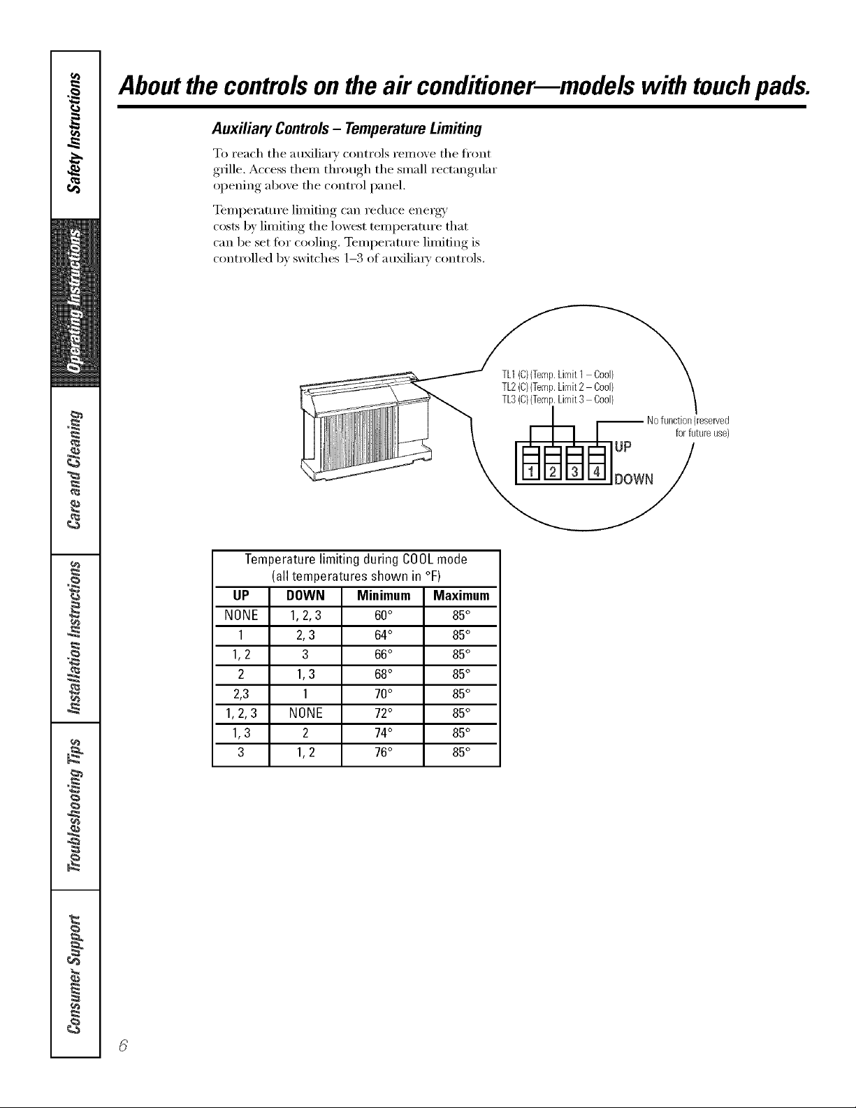
Auxiliary Controls- TemperatureLimiting
To reach the auxiliary controls remove the fl'ont
g_ille. Access them through the small rectangular
opening above the control panel.
Temperature limiting can reduce energy
costs by limiting the lowest temperature that
can be set for cooling. Temperature limiting is
controlled bv switches 1-3 of a u_lia_w controls.
TL1(C){Temp.Limit1 Cod)
TL2(C){Temp.Limit2 Cool)
TL3(C}{Temp.Limit3 Cool}
-- Nofunction(reserved
UP
DOWN
for futureuse)
Temperaturelimiting during COOLmode
(all temperatures shown in °F)
UP DOWN Minimum Maximum
NONE 1, 2, 3 60° 85°
1 2,3 64° 85°
1,2 3 66° 85°
2 1,3 68° 85°
2,3 1 70° 85°
1,2,3 NONE 72° 85°
1,3 2 74° 85°
3 1,2 76° 85°
@
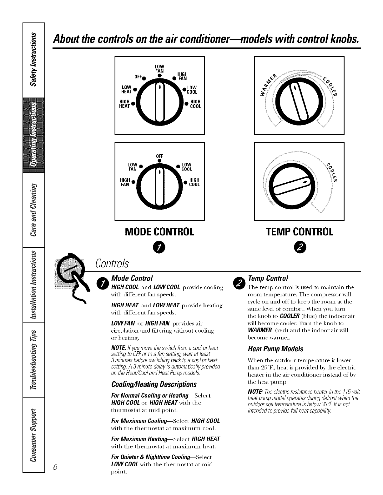
Aboutthecontrolsontheair conditioner--modelswith controlknobs.
LOW
OFF • HIGH
LOW_ _ I I I _ ALOW
FAN
r_j_l _ FAN
HEAT'!I I yCOOL
HIGH_ll I I Ill HIGH
HEAT--_" COOL
OFF
LOWa _ a LOW
FAN_COOL
HIGHm • I I •_ HIGH
FAN w_w COOL
i
S
/
/
MODECONTROL TEMPCONTROL
o Mode Control
HIGHCOOLand LOWCOOLl)r°'_ide cooling
with different tim speeds,
HIGHHEATand LOWHEATprovide heating
with different Lm speeds,
LOWFAN or HIGH FAN provides air
circulation and filtering without cooling
or heating.
NOTE:If youmovetheswitchfromacoolorheat
settingtoOFForto afansetting waitat least
3 minutesbeforeswitchingbacktoa coolorheat
setting.A.?-minutedelayisautomat/ca//yprovided
ontheHeat/CoolandHeatPumpmodels.
Cooling/HeatingDescriptions
ForNormal CoolingorHeating--Select
HIGHCOOLor HIGHHEATwith the
thermostat at mid point.
ForMaximum Cooling--Select HIGHCOOL
with the therlnostat at n/axinmln cool.
0
o TempControl
The telnp control is used to inaii_tain the
room telnperature. The compressor will
cycle on and off to kee I) the room at the
same level of coi/lfi)i_t. _*\]/en vou turn
the knob to COOLER(blue) the indoor air
will become cooler. Turn the knob to
WARMER (red) and the indoor air will
be('oi/l e W}llI/l el:
Heat PumpModels
When the outdoor temperature is lower
than 25°E, heat is provided by the electric
heater in the air conditioner instead ot by
the heat pump.
NOTE"Theelectricresistanceheaterin the115-volt
heatpumpmodeloperatesduringdefrostwhenthe
outdoorcoil temperaturessbelow36°£It/2not
intendedtoprovidefurlheatcapability
For Maximum Heating_Select HIGH HEAT
with the thermostat at nlaxinlulll heat.
For Quieter & Nighttime Cooling---.Select
8
LOWCOOLwith the thern_ostat at mid
point.
 Loading...