

Page 1
Cool Only: AJCM 08, 10 ACD*
AJCM 10, 12 DCD*
AJCQ 06 LCD*
AJCQ 08, 10, 12 ACD*
AJCQ 09, 10, 12 DCD*
Heat/Cool: AJEM 12 DCD
AJEQ 06 LCD
AJEQ 08 ACD
AJEQ 09, 10, 12 DCD
Write the model and serial
numbers here:
Model #____________________
Serial #
______________________
Find these numbers on a label on
the front of the base pan behind the
front grille.
Air Conditioners
GEAppliances.com
Room
TINSEA568JBRZ 49-7597-2 05-09 JR
Safety Instructions . . . . . . . . . . 2, 3
Operating Instructions . . . . . .4-9
Care and Cleaning
Air Filter . . . . . . . . . . . . . . . . . . . . . . . . . . . 11
Front Grille . . . . . . . . . . . . . . . . . . . . . . . .10
Grille and Case . . . . . . . . . . . . . . . . . . . 10
Outdoor Coils . . . . . . . . . . . . . . . . . . . . . 10
Installation Instructions
Before You Begin . . . . . . . . . . . . . .12, 13
Installing a J-Model in
an Existing Wall Case . . . . . . . . . . . . .14
Through-the-Wall
Installation . . . . . . . . . . . . . . . . . . . . . . . . 15
Window Installation
(Optional) . . . . . . . . . . . . . . . . . . . . . . 16-21
Troubleshooting Tips . . . . . . . . 22
Normal Operating Sounds . . . . . . . . 22
Consumer Support
Consumer Support . . . . . . Back Cover
Warranty . . . . . . . . . . . . . . . . . . . . . . . . . 23
Owner’s Manual and
Installation Instructions
Español
For a Spanish version of this manual, visit
our Website at GEAppliances.com.
Para consultar una version en español de
este manual de instrucciones, visite nuestro
sitio de internet GEAppliances.com.
Française
For a French version of this manual, visit
our Website at GEAppliances.com.
Pour une version française de ce manuel
d’utilisation, veuillez visiter notre site web
à l’adresse GEAppliances.com.
As an ENERGY STAR®partner, GE has
determined that this product meets the
ENERGY STAR®guidelines for energy efficiency.
*E
NERGY STAR
®
labeled product
Page 2
2
Consumer Support Troubleshooting Tips Installation Instructions Care and Cleaning Operating Instructions Safety Instructions
IMPORTANT SAFETY INFORMATION.
READ ALL INSTRUCTIONS BEFORE USING.
WARNING!
Risk of electric shock.
Can cause injury or death. For your safety,
the information in this manual must be followed
to minimize the risk of fire, electric shock or
personal injury.
■ Use this appliance only for its intended
purpose as described in this Owner’s
Manual.
■ This air conditioner must be properly
installed in accordance with the Installation
Instructions before it is used.
■ Never unplug your air conditioner by pulling
on the power cord. Always grip plug firmly
and pull straight out from the receptacle.
■ Replace immediately all electric service
cords that have become frayed or
otherwise damaged. A damaged power
supply cord must be replaced with a new
power supply cord obtained from the
manufacturer and not repaired. Do not
use a cord that shows cracks or abrasion
damage along its length or at either the
plug or connector end.
■ Turn OFF and unplug your air conditioner
before making any repairs or cleaning.
NOTE: We strongly recommend that any
servicing be performed by a qualified
individual.
■ For your safety…do not store or use
combustible materials, gasoline or other
flammable vapors or liquids in the vicinity
of this or any other appliance.
■ All air conditioners contain refrigerants,
which under federal law must be removed
prior to product disposal. If you are getting
rid of an old product with refrigerants, check
with the company handling disposal about
what to do.
SAFETY PRECAUTIONS
WARNING! Risk of electric shock.
Can cause injury or death. This appliance must
be properly grounded. Do not, under any
circumstances, cut or remove the third (ground)
prong from the power cord. For personal safety,
this appliance must be properly grounded.
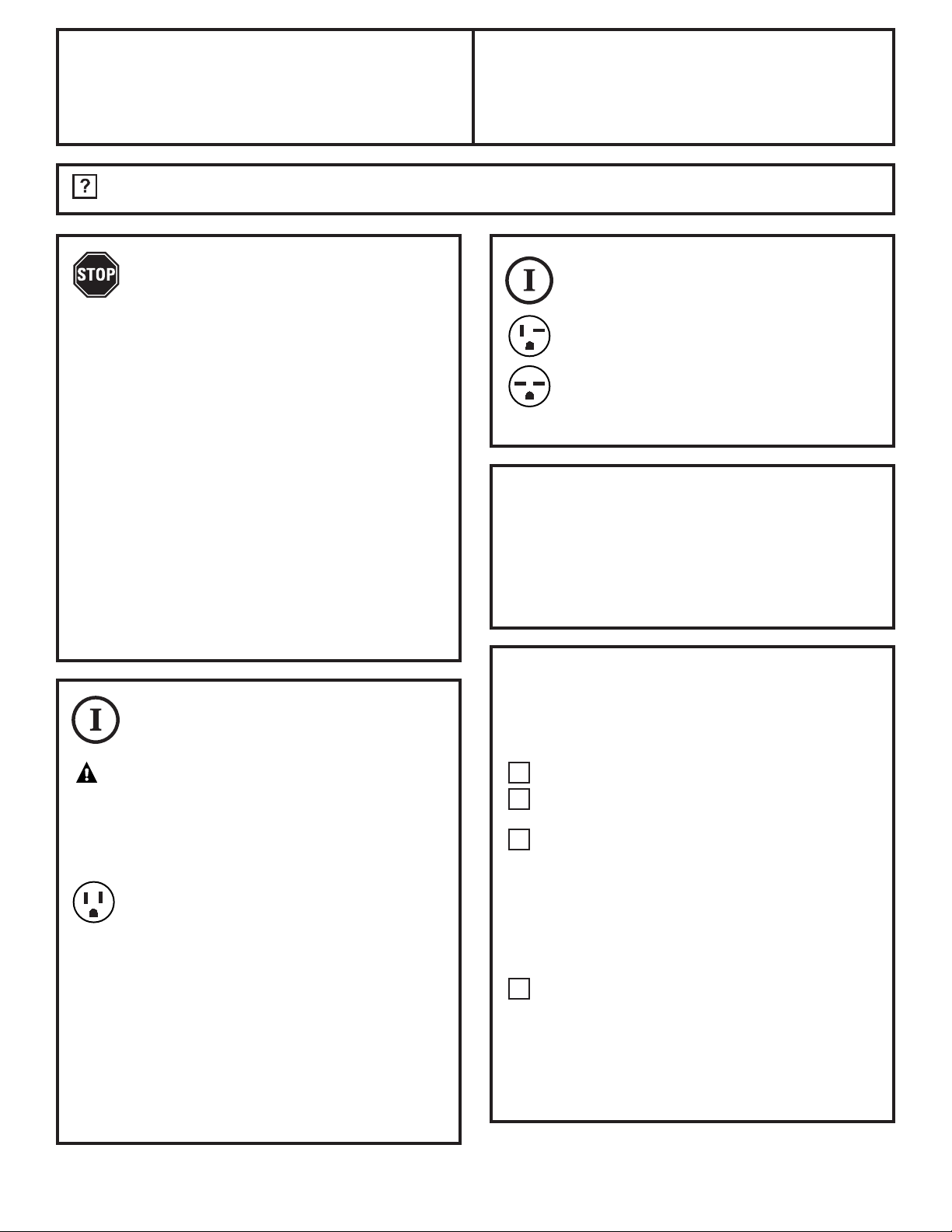
■ The power cord of this appliance is equipped
with a 3-prong (grounding) plug which mates
with a standard 3-prong (grounding) wall
outlet to minimize the possibility of electric
shock hazard from this appliance.
■ Have the wall outlet and circuit checked
by a qualified electrician to make sure
the outlet is properly grounded.
■ Power cord may include a current
interrupter device. A test and reset button is
provided on the plug case. The device should
be tested on a periodic basis by first pressing
the TEST button and then the RESET button.
If the TEST button does not trip or if the
RESET button will not stay engaged,
discontinue use of the air conditioner
and contact a qualified service technician.
■ Where a 2-prong wall outlet is encountered,
it is your personal responsibility and
obligation to have it replaced with a
properly grounded 3-prong wall outlet.
WARNING! Risk of electric shock.
Can cause injury or death.
■ The air conditioner should always be
plugged into its own individual electrical
outlet which has a voltage rating that
matches the rating plate. This provides
the best performance and also prevents
overloading house wiring circuits which
could cause a fire hazard from overheated
wires.
■ See the Installation Instructions, Electrical
Requirements section for specific electrical
connection requirements.
HOW TO CONNECT ELECTRICITY
SAVE THESE INSTRUCTIONS
Page 3
Safety Instructions Operating Instructions Care and Cleaning Installation Instructions Troubleshooting Tips Consumer Support
3
GEAppliances.com
WARNING! Risk of electric shock.
Can cause injury or death.
■ We strongly recommend against the use
of an extension cord.
■ If you must use an extension cord,
it is absolutely necessary that it be a ULlisted, 14-gauge, 3-wire grounding-type
appliance extension cord having a
grounding-type plug and outlet and that the
electrical rating of the cord be 15 amperes
(minimum) and 125 volts.
■ DO NOT use an extension cord with any
of the 230/208-volt models.
USE OF EXTENSION CORDS—115-Volt models only
WARNING! Risk of electric shock.
Can cause injury or death.
■ We strongly recommend against the use
of an adapter plug.
■ If you must use an adapter, where local
codes permit, a temporary connection
may be made to a properly grounded
2-prong wall outlet by use of a UL-listed
adapter available at most local hardware
stores.
■ The larger slot in the adapter must be
aligned with the larger slot in the wall outlet
to provide proper polarity in the connection
of the power cord.
■ When disconnecting the power cord from
the adapter, always hold the adapter in
place with one hand while pulling the power
cord plug with the other hand. If this is not
done, the adapter ground terminal is very
likely to break with repeated use.
■ If the adapter ground terminal breaks,
DO NOT USE the air conditioner until a
proper ground has been established.
■ Attaching the adapter ground terminal
to a wall outlet cover screw does not
ground the appliance unless the cover
screw is metal, not insulated, and the wall
outlet is grounded through the house wiring.
You should have the circuit checked by a
qualified electrician to make sure the outlet
is properly grounded.
USE OF ADAPTER PLUGS—115-Volt models only
READ AND FOLLOW THIS SAFETY INFORMATION CAREFULLY.
SAVE THESE INSTRUCTIONS
Page 4
4
Consumer Support Troubleshooting Tips Installation Instructions Care and Cleaning Operating Instructions Safety Instructions
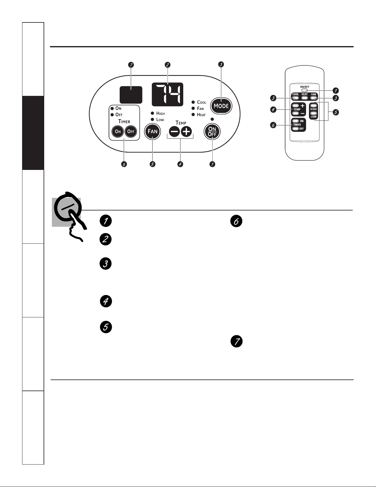
■ To ensure proper operation, aim the remote
control at the signal receiver on the air
conditioner.
■ The remote control signal has a range
of up to 21 feet.
■ Make sure nothing is between the air
conditioner and the remote control that could
block the signal.
■ Make sure batteries are fresh and installed
correctly—see the Care and Cleaning section.
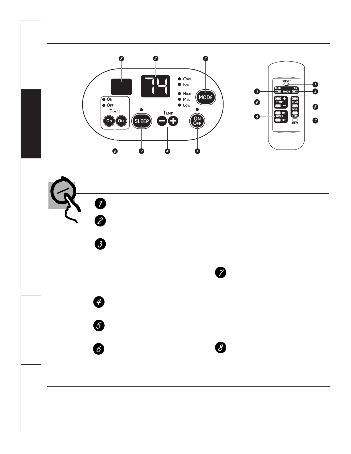
Air Conditioner Controls
ON/OFF
Turns air conditioner on and off.
Display
Displays the temperature setting. Displays
hours when setting the timer.
MODE
On the remote control, use to set the air
conditioner to COOL or FAN mode.
On the air conditioner controls, use to set
COOL or FAN mode at HIGH, MED or LOW
fan speed. Indicator lights on the air
conditioner controls will show the mode
and fan speed selected.
TEMP Increase + /Decrease – Pads
Use to set temperature when in COOL
mode.
Fan Speeds (Remote control only)
Use to set the fan speed at LOW, MED
or HIGH.
TIMER
ON—When the air conditioner is off, it can
be set to automatically turn on in half an
hour to 24 hours at its previous setting.
Each touch will set the time in half hours up
to 10 and then in hours up to 24.
To cancel the On Timer, press the ON pad
until the display time disappears.
OFF—When the air conditioner is on, it can
be set to automatically turn off in half an
hour to 24 hours. Each touch will set the
time in half hours up to 10 and then in hours
up to 24.
To cancel the Off Timer, press the OFF pad
until the display time disappears.
SLEEP
Press to set the air conditioner to run for
8 hours before it automatically returns to
the previous setting.
When the sleep timer is set, the set
temperature will automatically increase
2°F after the second hour then 1°F each
hour over the next two hours.
To cancel the sleep mode, press the MODE
pad or the SLEEP pad a second time.
Remote Control Signal Receiver
NOTE: When the air conditioner is turned on,
it will automatically start in the setting last used
.
Remote Control
About the controls on the air conditioner—Cool Only Models
Appearance may vary.
Remote Control
Lights beside the touch pads on the air conditioner
control panel indicate the selected settings.
Controls
Page 5

Safety Instructions Operating Instructions Care and Cleaning Installation Instructions Troubleshooting Tips Consumer Support
5
GEAppliances.com
COOL MODE
Remote Control
1. Press COOL pad.
2. Press LOW, MED or HIGH pads to set desired fan
speed.
3. Press the INCREASE + / DECREASE – pads to set
the desired temperature 60°F to 85°F in 1°F
increments.
Control Panel
1. Press the MODE pad until the COOL indicator light is lit
and the LOW, MED or HIGH indicator light is lit for the
desired fan speed.
2. Press the INCREASE + / DECREASE – pads to set the
desired temperature 60°F to 85°F in 1°F increments.
A thermostat is used to maintain the room temperature.
The compressor will cycle on and off to keep the room
at the set level of comfort. Set the thermostat at a lower
number and the indoor air will become cooler.
Set the thermostat at a higher number and the indoor air
will become warmer.
NOTE: If the air conditioner is off and is then turned on
while set to COOL, it will take approximately 3 minutes
for the compressor to start and cooling to begin.
Cooling Descriptions
For Normal Cooling—Select the COOL mode and HIGH
or MED fan with a middle set temperature.
For Maximum Cooling—Select the COOL mode
and HIGH fan with a lower set temperature.
For Quieter and Nighttime Cooling—Select the COOL
mode and LOW fan with a middle set temperature.
NOTE: If you switch from a COOL setting to OFF or to
a fan setting, wait at least 3 minutes before switching
back to a COOL setting.
FAN MODE
Use the FAN mode to provide air circulation and filtering
without cooling. Since fan-only settings do not provide
cooling, a temperature setting will not be displayed.
Remote Control
Press FAN pad. Press LOW, MED or HIGH pads to set
desired fan speed.
Control Panel
Press the MODE pad until the FAN indicator light is lit
and the LOW, MED or HIGH indicator light is lit for the
desired fan speed.
Page 6
6
Consumer Support Troubleshooting Tips Installation Instructions Care and Cleaning Operating Instructions Safety Instructions
■ To ensure proper operation, aim the
remote control at the signal receiver
on the air conditioner.
■ The remote control signal has a range
of up to 21 feet.
■ Make sure nothing is between the air
conditioner and the remote control that could
block the signal.
■ Make sure batteries are fresh and installed
correctly—see the Care and Cleaning section.
Air Conditioner Controls
ON/OFF
Turns air conditioner on and off.
Display
Displays the temperature setting. Displays
hours when setting the timer.
MODE
On the air conditioner controls, use to set
COOL, HEAT or FAN mode. Indicator lights
on the air conditioner controls will show the
mode selected.
TEMP Increase + /Decrease – Pads
Use to set temperature when in COOL
or HEAT mode.
FAN Speeds
Use to set the fan speed at LOW or HIGH.
Indicator lights will show the speed selected.
TIMER
ON—When the air conditioner is off, it can
be set to automatically turn on in half an
hour to 24 hours at its previous setting.
Each touch will set the time in half hours
up to 10 and then in hours up to 24.
To cancel the On Timer, press the ON pad
until the display time disappears.
OFF—When the air conditioner is on, it can
be set to automatically turn off in half an
hour to 24 hours. Each touch will set the
time in half hours up to 10 and then in hours
up to 24.
To cancel the Off Timer, press the OFF pad
until the display time disappears.
Remote Control Signal Receiver
NOTE: When the air conditioner is turned on,
it will automatically start in the setting last used
.
Remote Control
About the controls on the air conditioner—Heat/Cool Models
Appearance may vary.
Remote Control
Lights beside the touch pads on the air conditioner
control panel indicate the selected settings.
Controls
Page 7
Safety Instructions Operating Instructions Care and Cleaning Installation Instructions Troubleshooting Tips Consumer Support
GEAppliances.com
COOL MODE
Remote Control
1. Press COOL pad.
2. Press LOW or HIGH pads to set desired fan speed.
3. Press the INCREASE + / DECREASE – pads to set the
desired temperature 60°F to 85°F in 1°F increments.
Control Panel
1. Press the MODE pad until the COOL indicator light is lit.
2. Press the FAN pad until HIGH or LOW indicator light
is lit for desired fan speed.
3. Press the INCREASE + / DECREASE – pads to set the
desired temperature 60°F to 85°F in 1°F increments.
A thermostat is used to maintain the room temperature.
The compressor will cycle on and off to keep the room
at the set level of comfort. Set the thermostat at a lower
number and the indoor air will become cooler.
Set the thermostat at a higher number and the indoor air
will become warmer.
NOTE: If the air conditioner is off and is then turned on
while set to COOL, it will take approximately 3 minutes
for the compressor to start and cooling to begin.
Cooling Descriptions
For Normal Cooling—Select the COOL mode and HIGH
fan with a middle set temperature.
For Maximum Cooling—Select the COOL mode
and HIGH fan with a lower set temperature.
For Quieter and Nighttime Cooling—Select the COOL
mode and LOW fan with a middle set temperature.
NOTE: There will be a 3-minute delay between setting
changes such as COOL to OFF and back to COOL.
FAN
Use the FAN to provide air circulation and filtering without
cooling or heating. Since fan only settings do not provide
cooling or heating, a temperature setting will not be
displayed.
Remote Control
Press FAN pad. Press LOW or HIGH pads to set desired
fan speed.
Control Panel
Press the MODE pad until the FAN indicator light is lit
and the LOW or HIGH indicator light is lit for the desired
fan speed.
HEAT MODE
Remote Control
1. Press HEAT pad.
2. Press LOW or HIGH pads to set desired fan speed.
3. Press the INCREASE + / DECREASE – pads to set the
desired temperature 60°F to 85°F in 1°F increments.
Control Panel
1. Press the MODE pad until the HEAT indicator light is lit.
2. Press the FAN pad until HIGH or LOW indicator light
is lit for desired fan speed.
3. Press the INCREASE + / DECREASE – pads to set the
desired temperature 60°F to 85°F in 1°F increments.
A thermostat is used to maintain the room temperature.
The compressor will cycle on and off to keep the room
at the set level of comfort. Set the thermostat at a higher
number and the indoor air will become warmer.
Set the thermostat at a lower number and the indoor air
will become cooler.
NOTE: If the air conditioner is off and is then turned on
while set to HEAT, it will take approximately 3 minutes
for the compressor to start and heating to begin.
Heating Descriptions
For Normal Heating—Select the Heat mode and HIGH
fan with a middle set temperature.
For Maximum Heating—Select the HEAT mode
and HIGH fan with a higher set temperature.
For Quieter and Nighttime Heating—Select the HEAT
mode and LOW fan with a middle set temperature.
NOTE: There will be a 3-minute delay between setting
changes such as HEAT to OFF and back to HEAT.
7
Page 8
No function (reserved
for future use)
8
Consumer Support Troubleshooting Tips Installation Instructions Care and Cleaning Operating Instructions Safety Instructions
About the controls on the air conditioner
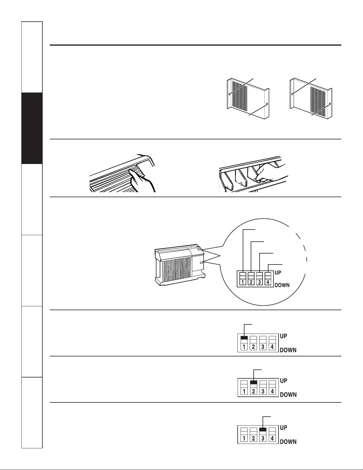
Auxiliary Controls – Dip Switches (location varies by model)
Vent Control
The vent control is located behind the front grille on the
right side of the air discharge area. When CLOSED, only
the air inside the room will be circulated and conditioned.
When OPEN, the vent allows outdoor fresh air exchange.
To open or close the vent:
1. Remove the front grille.
2. Remove the vent card screw.
3. Remove vent card, turn it over and replace it by
locating rear hole in card over locating pin inside air
discharge and reattaching screw at front.
Horizontal louvers
on the front grille let
you control the air
direction up and down.
Remove the front grille
to adjust the vertical
louvers side-to-side
to direct the air left
or right.
Air Direction
Locating hole
Screw hole
OPEN position
(Mesh end toward back)
CLOSE position
(Mesh end toward front)
Locating hole
Screw hole
The unit leaves the factory set at the CLOSE position.
The auxiliary dip switch controls are located
behind the room cabinet—as shown in this figure.
The owner is responsible for checking switches
and ensuring they are in the desired position.
Fan Cycle/Continuous - Cool
Fan Cycle/Continuous - Heat (on some models)
Class 2 (on some models)
Fan Cycle/Continuous - Cool
When this switch is enabled (UP), it allows the indoor
fan to cycle on/off with the compressor. When this
switch is disabled (DOWN), it allows the indoor fan to run
continuously. The default setting is down (continuous).
Fan Cycle/Continuous - Heat (on some models)
When this switch is enabled (UP), it allows the indoor fan
to run continuously with the heater operation. When this
switch is disabled (DOWN), it allows the indoor fan to
cycle on/off. The default setting is down (cyclic).
Class 2 - Remote Thermostat (on some models)
When this switch is enabled (UP), it allows the unit
to operate with a Class 2 Remote Control Wall
Thermostat. The unit controls are disabled.
The default setting is down (disabled).
Fan Cycle/Continuous - Cool
Fan Cycle/Continuous - Heat (on some models)
Class 2 (on some models)
Page 9
9
Safety Instructions Operating Instructions Care and Cleaning Installation Instructions Troubleshooting Tips Consumer Support
GEAppliances.com
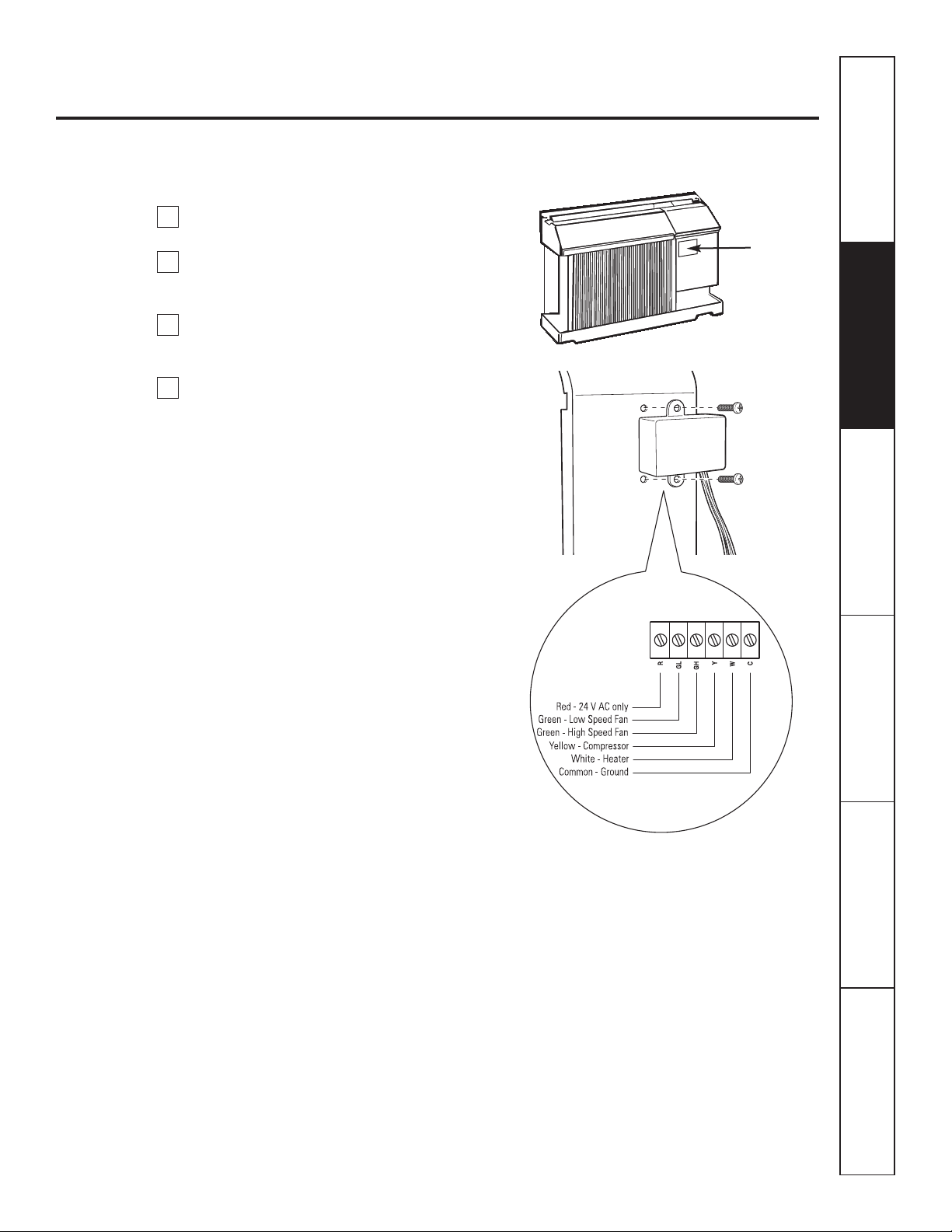
When connected, the unit will be controlled
by a remote thermostat.
NOTE: The number 3 dip switch must be in
the enabled (UP) position to activate the remote
thermostat. (See the installation instructions
supplied with the remote thermostat.)
IMPORTANT:
The thermostat connections provide 24 V AC only.
If using a digital/electronic wall thermostat,
ensure it is compatible with 24 VAC signal. See
the Installation Instructions for the wall thermostat.
NOTICE:
Damage to a wall thermostat or to the electronics
can result from improper connections. Special care
must be used in connecting the wires. No line
voltage connections should be made to any circuit.
Isolate all wires in building from line voltage.
Terminal Connections Remote Thermostat - Class 2 (on some models)
The controls are located under a plastic cover
behind the front grille.
Remove the front grille. See the Front Grille
section of Care and Cleaning.
Remove the screws securing the plastic cover
over the wiring connections. Set aside screws
and plastic cover.
To make wiring connections, insert the wires
into the bottom of the terminals and tighten
screws securely.
After all desired connections have been made,
replace the plastic cover and front grille.
The owner is responsible for making all
connections and setting the appropriate dip
switches.
2
4
3
1
Terminal
connections
location
under front
grille
Page 10
Consumer Support Troubleshooting Tips Installation Instructions Care and Cleaning Operating Instructions Safety Instructions
10
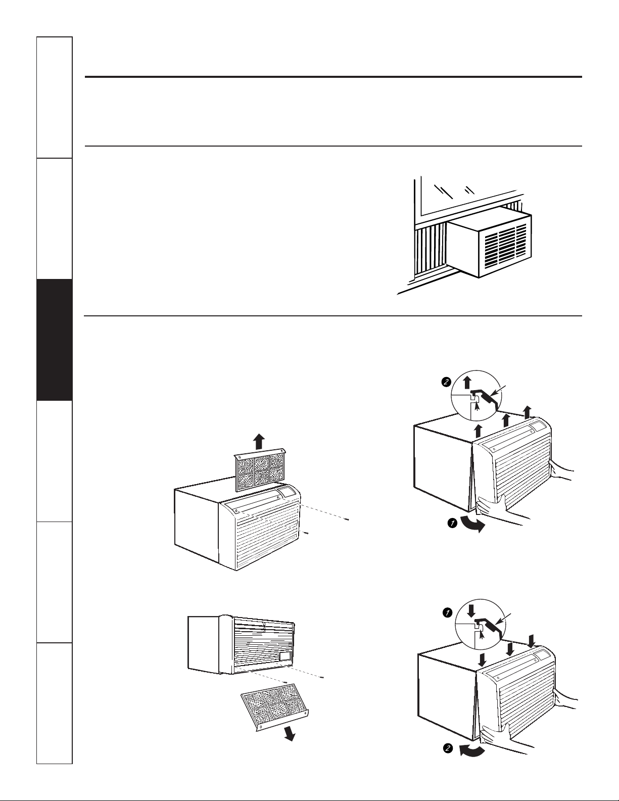
The front grille can be removed for more thorough
cleaning and to locate the model and serial
numbers on the front of the base pan.
To remove:
1. Pull the filter out.
2. Remove the two grille screws.
3. Pull the grille out from the bottom and lift up
from the tabs on the top of the case.
To replace:
Hook the tabs on the front grille even with the tabs
on the case and snap into place.
Replace the screws and filter.
Front Grille
Outdoor Coils
The coils on the outdoor side of the air conditioner
should be checked regularly.
If they are clogged with dirt or soot they may be
professionally steam cleaned, a service available
through your GE service outlet.
Grille and Case
Turn the air conditioner off and remove the plug
from the wall outlet before cleaning.
To clean, use water and a mild detergent.
Do not use bleach or abrasives.
Grille
Tab
Grille
Tab
On some models
On some models
Care and cleaning of the air conditioner.
Page 11
How to Insert the Batteries in the Remote Control
Remove the battery cover by sliding it
according to the arrow direction.
Insert new batteries making sure that the
(+) and (–) of battery are installed correctly.
Reattach the cover by sliding it back
into position.
NOTES:
■ Use 2 AAA (1.5 volt) batteries. Do not use
rechargeable batteries.
■ Remove the batteries from the remote control
if the system is not going to be used for a long
time.
3
2
1
11
GEAppliances.com
Safety Instructions Operating Instructions Care and Cleaning Installation Instructions Troubleshooting Tips Consumer Support
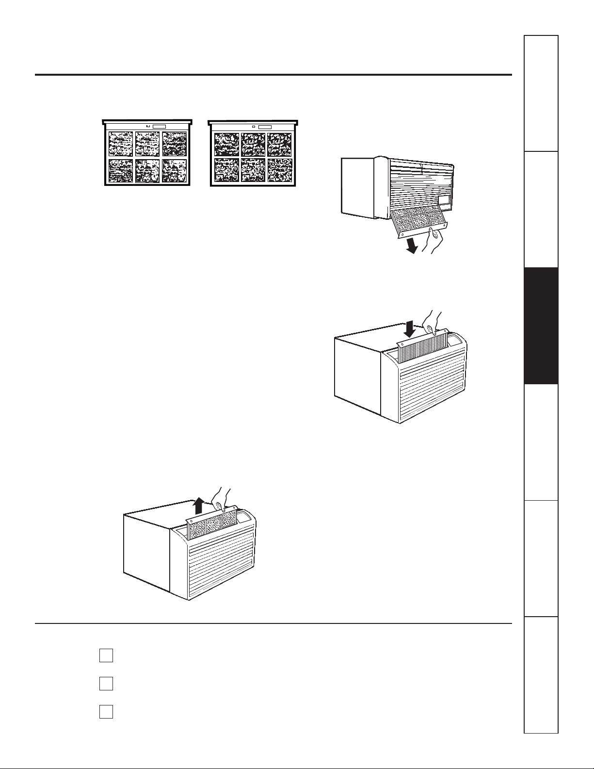
To maintain optimum performance, clean the filter at least every 30 days.
Air Filter
Turn the air conditioner off before cleaning.
The most important thing you can do to maintain
the air conditioner is to clean the filter at least
every 30 days. A clogged filter reduces cooling,
heating and air flow.
Keeping the air filter clean will:
■ Decrease cost of operation.
■ Save energy.
■ Prevent clogged heat exchanger coils.
■ Reduce the risk of premature component failure.
To clean the air filters:
■ Vacuum off the heavy soil.
■ Run water through the filters.
■ Dry thoroughly before replacing.
To remove the air filter, on some models:
Carefully pull the tab forward, up and out.
To remove the air filter, on other models:
Pull it down.
To replace the air filter:
Replace the clean filter by pushing it back
into place.
NOTICE:Do not operate the air
conditioner without the filter in place. If a filter
becomes torn or damaged it should be replaced
immediately.
Operating without the filter in place or with a
damaged filter will allow dirt and dust to reach
the indoor coil and reduce the cooling, heating,
airflow and efficiency of the unit.
Replacement filters are available from your
salesperson, GE dealer, GE Service and Parts Center
or authorized Customer Care
®
servicers.
Dirty filter—Needs cleaning Clogged filter—Greatly
reduces cooling, heating
and airflow.
FRONT
FRONT
Page 12
ELECTRICAL REQUIREMENTS
WARNING! Risk of electric shock. Can
cause injury or death. This appliance must be
properly grounded. Where a 2-prong wall outlet
is encountered, it is your responsibility and
obligation to have it replaced with a properly
grounded 3-prong outlet.
Some models require a 115/120-volt a.c.,
60-Hz grounded outlet protected with a
15-amp time delay fuse or circuit breaker.
The 3-prong grounding plug minimizes the possibility of
electric shock hazard. If the wall outlet you plan to use is
only a 2-prong outlet, it is your responsibility to have it
replaced with a properly grounded 3-prong wall outlet.
Do not, under any circumstances, cut or remove
the third (ground) prong from the power cord.
Do not change the plug on the power cord of this
air conditioner.
Aluminum house wiring may present special
problems—consult a qualified electrician.
BEFORE YOU BEGIN
Read these instructions completely
and carefully.
•
IMPORTANT — Save these instructions
for local inspector’s use.
•
IMPORTANT — Observe all governing codes
and ordinances.
• Note to Installer – Be sure to leave these instructions
with the Consumer.
• Note to Consumer – Keep these instructions
for future reference.
• Skill level – Installation of this appliance requires basic
mechanical skills.
• Completion time – Approximately 1 hour
• We recommend that two people install this product.
• Proper installation is the responsibility of the installer.
• Product failure due to improper installation
is not covered under the Warranty.
Questions? Call 800.GE.CARES (800.432.2737) or Visit our Website at: GEAppliances.com
Installation
Air Conditioner
Instructions
12
ELECTRICAL REQUIREMENTS (cont.)
Some models require 230/208-volt a.c., protected
with a time delay fuse or circuit breaker. These
models should be installed on their own single
branch circuit for best performance and to prevent
overloading house or apartment wiring circuits,
which could cause a possible fire hazard from
overheating wires.
IMPORTANT!
GE strongly recommends the removal of the old wall case
and the installation of a new GE Wall Case. If you decide to
keep the existing wall case, you may need a kit to ensure
proper performance. If you DO NOT use a kit, you run the
risk of poor performance or product failure. This is not
covered under the terms of the GE warranty.
J-MODEL QUALIFYING QUESTIONS
J-model air conditioners may fit in existing wall cases.
However, they often need a kit to properly adapt the case
to the GE air conditioner. Answer these questions and see
the chart on the next page for the proper kit.
What brand air conditioner will you be replacing?
What are the dimensions of the wall case currently
in use?
What is the model number of the chassis
currently in use? What is the model (or Type) number
of the wall case currently in use?
Frequently, the J-model adapter kit will apply to another
brand model “series” or specific vintage. In these cases,
you need the chassis model number and/or the wall
case or “type” number to confirm the use of the correct
adapter kit.
What type of outdoor grille is used with the current
wall case?
There may be an architectural grille attached to a wall
case to enhance the exterior appearance of the building.
Custom grilles may be used with J-model wall cases
provided a J-model adapter kit is also used to ensure
proper airflow.
D
C
B
A
Page 13
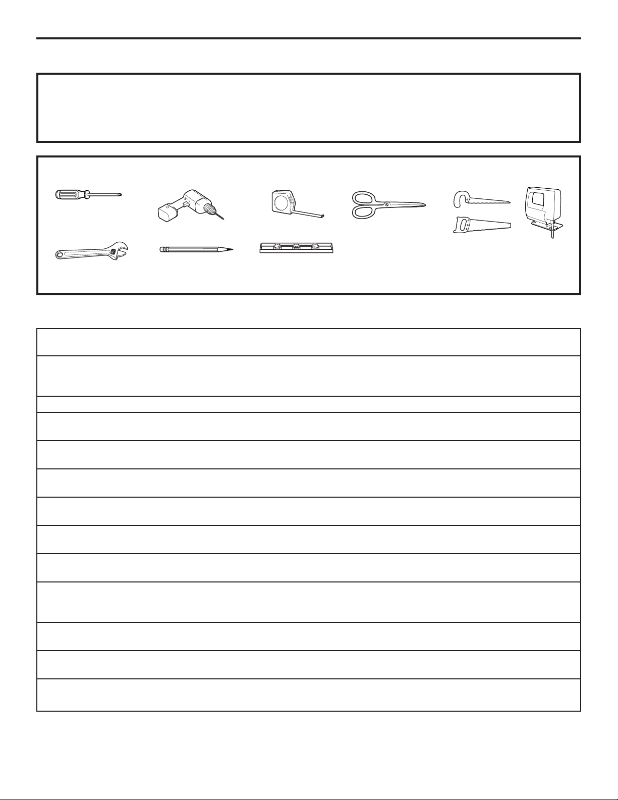
TOOLS YOU MAY NEED
13
GE KIT NUMBERS
Power cord may include a current interrupter device.
A test and reset button is provided on the plug case.
The device should be tested on a periodic basis by first
pressing the TEST button and then the RESET button.
If the TEST button does not trip or if the RESET button
will not stay engaged, discontinue use of the air
conditioner and contact a qualified service technician.
Installation Instructions
USE GE
KIT NUMBER: FOR: DESCRIPTION:
RAB46A, 47A Use these kits for all GE Standard wall case for “J” model chassis. RAG13 stamped
& 48A models and other brands aluminum exterior grille included. Remove the existing case
not listed and replace.
RAK65A1 All GE Models Kit for window installation.
RAK56A100 GE RAB13, 14 & 15 Fits all GE wall cases 26″W x 18″H x 24″D.
(ACLB & RCL Chassis)
RAK1072 Hotpoint ACXB10 & 11 Adapts an older Hotpoint wall case to a “J” model chassis.
(ACTB Chassis) Fits Hotpoint wall cases 253⁄4″W x 167⁄8″H x 185⁄8″D.
RAK1082 Whirlpool Type 23W Adapts Whirlpool wall case to a “J” model chassis.
Wall Case Fits Whirlpool wall cases 257⁄8″W x 161⁄2″H x 231⁄8″D.
RAK1102 GE RAB30 Adapts GE wall case to a “J” model chassis.
(“F” models) Fits the RAB 30 wall case 26″W x 18″H x 24″D.
RAK123A64 Fedders Wall Case “A” Adapts Fedders wall case to a “J” model chassis.
Fits Fedders wall cases 27″W x 163⁄4″H x 163⁄4″D.
RAK126 Westinghouse Wall Case Adapts Westinghouse wall case to a “J” model chassis.
(Type 2626D73H01) Fits Westinghouse wall cases 257⁄8″W x 157⁄16″H x 16″D.
RAB46, 47 & 48 Use these kits for all Standard wall case for “J” model chassis. RAG13 stamped
other brands not listed. aluminum exterior grille included. Remove the existing case
and replace.
RAK690 RAB36, 37, 38, 46, 47 or 48 If you attach a custom architectural outdoor grille, use this kit
(J-Chassis) to ensure proper airflow.
RAG13 RAB36, 37, 38, 46, 47 or 48 Standard aluminum exterior grille (included with RAB46, 47
(J-Chassis) and 48 wall cases).
RAG14E RAB36, 37, 38, 46, 47 or 48 Architectural louvered exterior grille.
(J-Chassis)
Adjustable Wrench
Level
Phillips-head
screwdriver
Hand or Saber Saw
Drill
Pencil
Ruler or Tape Measure
Scissors or knife
Read these instructions completely and carefully.
Page 14
REMOVE ALL SHIPPING PADS
(IF PRESENT) INSIDE AIR CONDITIONER
NEXT TO COMPRESSOR
Installation Instructions
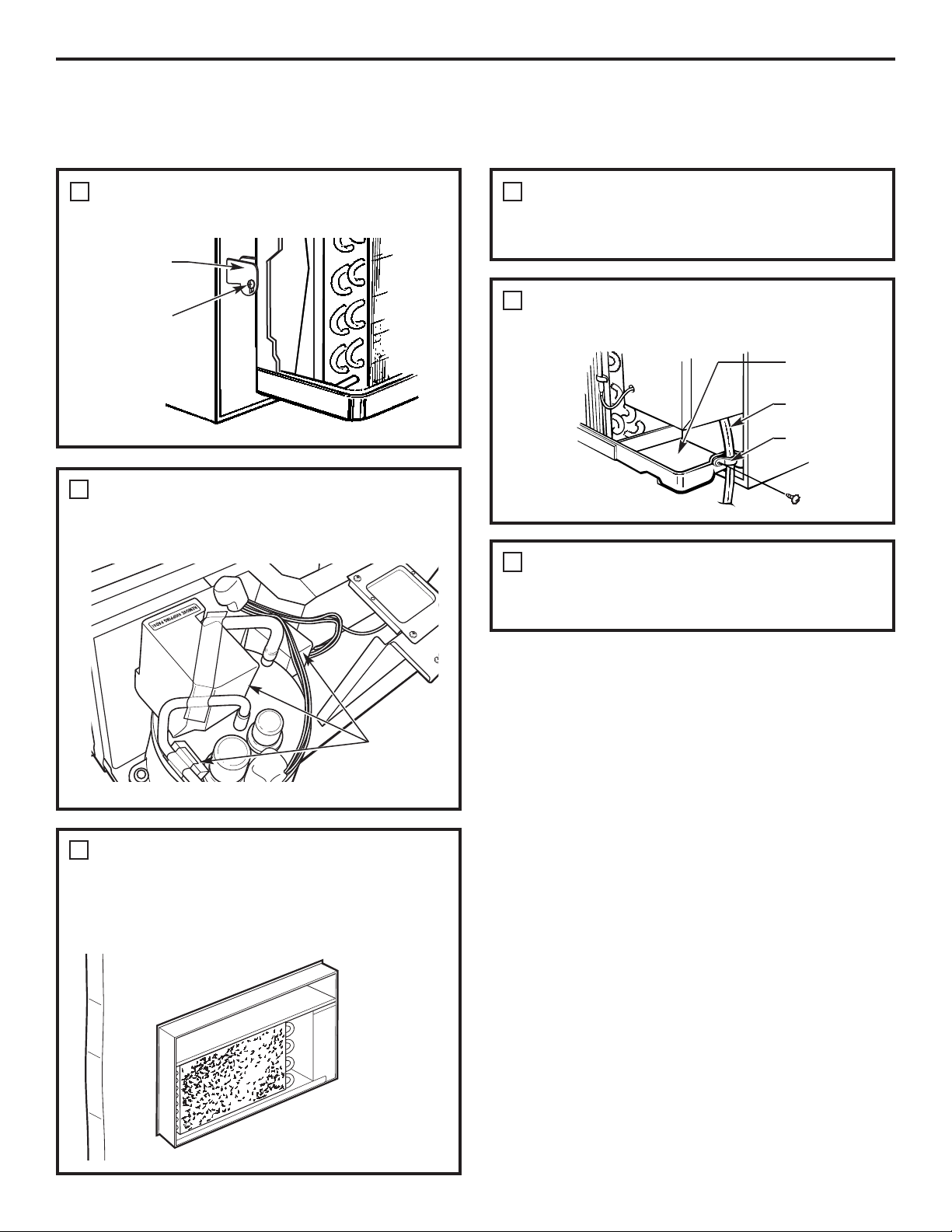
REMOVE LOCKING PLATE ON FRONT
LEFT SIDE
1
REINSTALL LOCKING PLATE WITH TAB
BEHIND WALL CASE FLANGE. TIGHTEN
SCREW
Locking
plate
Remove
screw
INSTALLING A J-MODEL IN AN EXISTING WALL CASE
Read these instructions completely and carefully.
Remove
shipping
pads (if
present)
CAREFULLY SLIDE AIR CONDITIONER
BACK INTO CASE
Make sure that the tubing on the unit does
not touch the wall case and that the case
installation is secure.
2
3
14
ATTACH FRONT GRILLE
An opening for the power cord is on the bottom
of the front grille.
ATTACH POWER CORD TO BASE PAN
WITH CLAMP
Clamp
Power cord
Base pan
4
5
6
Page 15
15
Installation Instructions
PREPARE OPENING IN WALL
Make certain a wall receptacle is available close
to the hole location or make arrangements to install
a receptacle.
The cord length for the 115-volt models is 72″
to the right and 47″ to the left.
For the 230/208-volt models the cord length is 65″
to the right and 39″ to the left.
1
INSTALLING THROUGH THE WALL
Read these instructions completely and carefully.
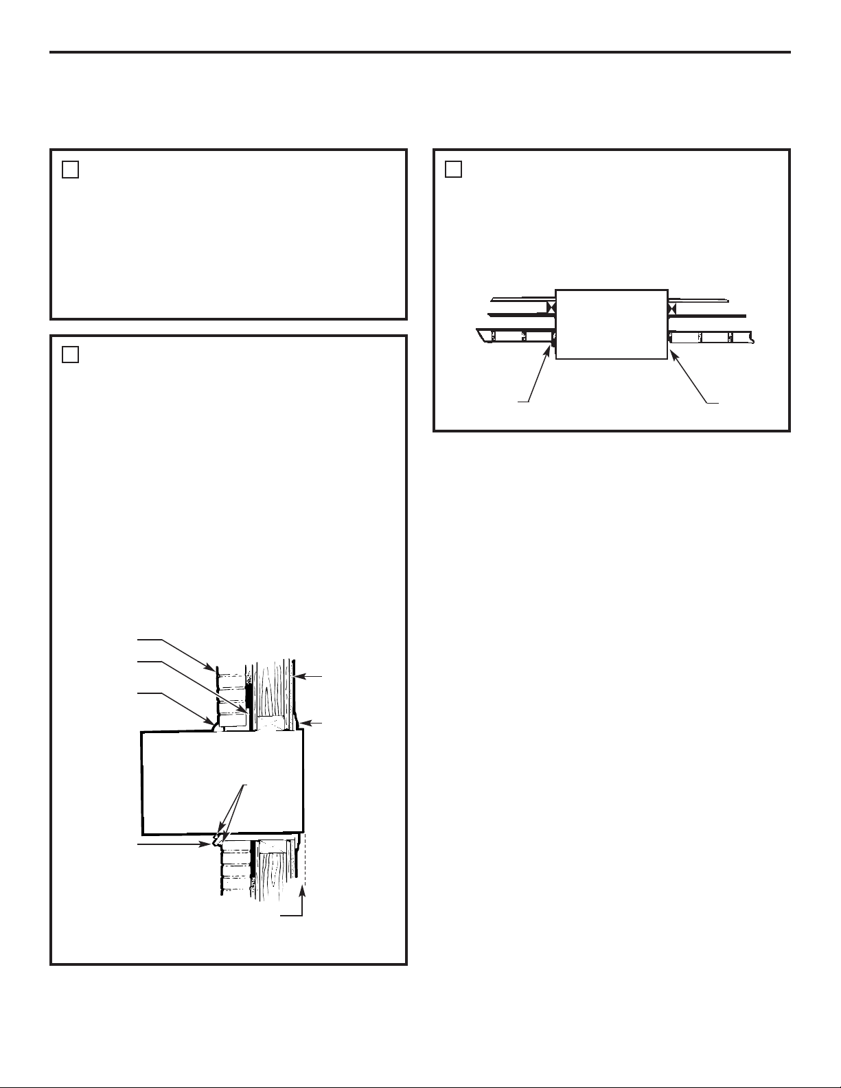
SUPPORT REQUIREMENTS FOR AIR
CONDITIONER
The air conditioner wall case may be installed
with 1/4″ min. extension out from the inside wall
or with 1/4″ min. extension out from the outside wall.
The finished sides of the opening should be structural
wall members.
Lintel – Use a lintel in brick veneer and brick
and block types of wall to support the bricks
or blocks above the opening. Do not allow the wall
case to be used in lieu of a lintel.
Flashing – Install flashing (drip rail) as shown
to prevent water from dripping inside the wall
and down the outside of the building.
2
Trim molding
(if desired)
Plaster line
Caulking
(above
and below
the flashing)
Flashing
(drip rail)
1/4″ min. extension
inside the wall from
the trim molding
Room side
Brick veneer
Lintel angle
(if required)
Caulking
(on all 4 sides
on the outside
and inside
of the case)
SUPPORT REQUIREMENTS FOR AIR
CONDITIONER
Mortar between the case and the brick wall around
the case may be undercut at about 45° for
improved caulking.
3
Caulking
Top of case
Inside
Outside
Undercut
mortar
Page 16

Installation Instructions
16
WINDOW INSTALLATION—OPTIONAL
WARNING! Risk of injury. Installation must comply with these guidelines.
Requires optional accessory kits RAK65A1 and Wall Sleeve RAB46A, 47A or 48A
Read these instructions completely and carefully.
Air conditioner
Type C (painted) (6)
Type D (2)
Type E (4)
Large washer (2)
Adjusting bolt (2)
Lock nut (2)
Spacer (2)
Support bracket hardware
Type A (9)
Type B (2)
Sill support
bracket (2)
2 angles
(left and right
hand)
Case side
gasket (2)
Spring
clip (4)
Window
locking
bracket
Vinyl window gasket
Bottom window gasket
Filler Panels
Cut panels
and discard
center piece
Case top gasket
Foam top
window gasket
B
Right side
A
Left side
(holes are on the left)
(holes are on the right)
WINDOW REQUIREMENTS
• These instructions are for a standard double-hung window.
You will need to modify them for other types of windows.
• The air conditioner can be installed without the accordion
panels if needed to fit in a narrow window. See the window
opening dimensions to the right.
• All supporting parts must be secured to firm wood,
masonry or metal.
• The electrical outlet must be within reach of the power
cord.
1
Window opening dimensions are for
a standard double-hung window.
17″ min.
31″ to 43″
(With filler panels)
26
1
⁄4″ min. (Without filler panels)
Page 17
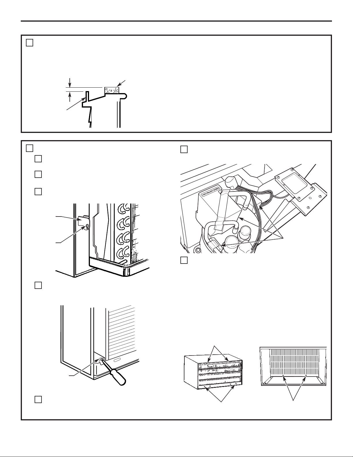
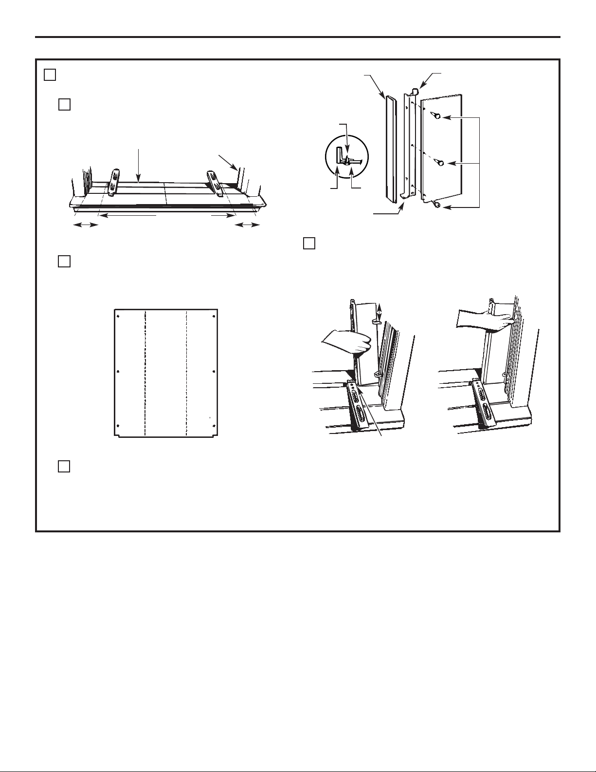
REMOVE AIR CONDITIONER FROM CASE
Remove the front grille. See the Care and Cleaning
section.
Find the locking plate located on the front
left side.
Remove the screw and the locking plate to unlock
the air conditioner.
Remove and discard the shipping screw
on the back of the air conditioner to allow removal
of the air conditioner from the case.
Pull the bottom corners of the air conditioner
and slide it out of the case.
Remove all shipping pads (if present) inside the air
conditioner next to the compressor.
Remove the rear grille that is taped to the back
of the case. Remove the packet of screws taped
to the back of the grille. While holding the grille at a
45° angle, insert it into the clips at the top of the case
and push the bottom in. Keep slight upward pressure
on the grille until it fits flush with the bottom of the
case.
17
STORM WINDOW REQUIREMENTS
A storm window frame will not allow the air
conditioner to tilt towards the outside and will keep
it from draining properly. To adjust for this, attach
a piece of wood to the stool.
WOOD PIECES
WIDTH: 2″
LENGTH: Long enough to fit inside the window frame.
THICKNESS: To determine the thickness, place a piece
of wood on the stool to make it 1/2″ higher than the top
of the storm window frame.
Attach securely with nails or screws provided by
the installer.
2
1/2″ higher
than frame
Storm
window
frame
Wood
Stool
Sill
3
A
B
C
Locking
plate
Remove
screw
D
Remove
screw
E
F
If attaching the grille
from the outside of the
case, use the 2 long screws.
If attaching the grille
from the inside of the case,
use the 2 short screws.
G
Clips
Insert the 2 long screws
on the outside
Insert the 2 short screws
on the inside
Installation Instructions
Remove shipping pads
(if present)
Page 18
Installation Instructions
18
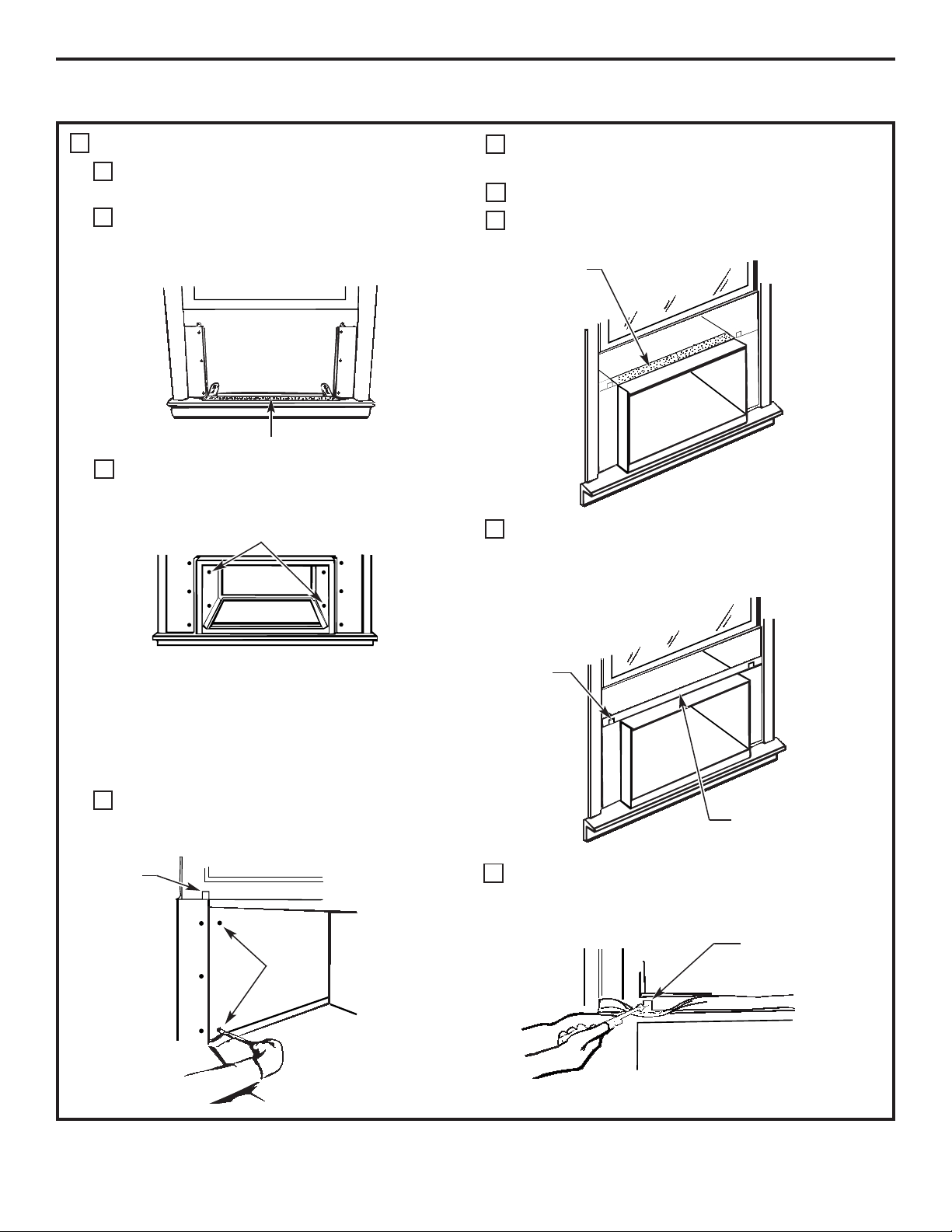
INSTALL SILL SUPPORTS
Assemble the sill supports. Do not fully tighten
the spacer mounting screws at this time.
Before attaching the sill supports, place them on
the window stool. Select the spacer position that
will place the spacer near the outermost point
on the sill. Tighten the spacer mounting screws.
Turn the bolts and tighten the lock nuts to make
the sill supports level or tilt down 1/8″ to the outside.
Line up the “V” notch with 12
3
⁄8″ marks. Drill pilot holes
and attach the sill supports.
NOTES:
• On narrow sills, there may not be enough room to use
the lock nut.
• A deep offset sill may require a longer adjusting bolt
than the standard hex-head bolt provided.
• On wood sills use the large washer between the bolt
head and the sill. This prevents the bolt from digging
into the wood.
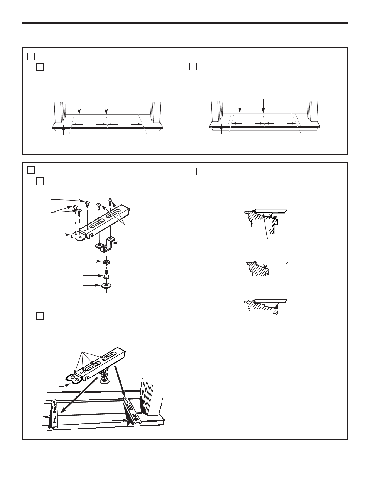
PREPARE WINDOW
Mark the centerline of the stool. Measure from the
centerline 13
3
⁄8″ on both sides for the panel cuts.
Measure 12
3
⁄8″ from the centerline on both sides
for the sill support brackets.
4
A
B
WINDOW INSTALLATION—OPTIONAL (cont.)
Stool
Sill
133⁄8″
Centerline
5
A
B
C
Sill support
Average sill
Narrow sill
Offset sill (such as brick or stone)
Spacer
Spacer
Type B
Type E
Spacer mounting
screws Type (A)
Lock nut
Sill support
Adjusting bolt
Large washer
(for use with wood sills)
Stool
Sill support
“V” notch
Screws are in position
Sill
Bolt
Stool
Sill
Outside
Outside
Inside
Inside
133⁄8″
123⁄8″
123⁄8″
Centerline
Inside
Outside
Page 19
Installation Instructions
19
MEASURE, CUT AND INSTALL FILLER
PANELS
Measure from the edge of the panel marks
(see Prepare the Window) to the inside of the
window track on each side (A and B).
Mark the A and B measurements on each side
of the filler panel board. Cut the panels and discard
the center piece. Note position of the notches.
Put together the panel assemblies. Remove
the paper backing from the case-side gasket
and attach it to the angle. Push a pencil point
through the gaskets to locate the holes in
the angles.
Install the panels in the window. Place the spring clips
3″ from the top and the bottom. Squeeze and push
the clips to fit in the window track and the tab into
the sill support.
6
A
B
C
D
Sill
A
Window track
Width of the air
conditioner
(panel marks)
Left side
B
Right side
133⁄8″ 133⁄8″
Filler Panels
Cut panels
and discard
center piece
B
Right
side
A
Left side
(holes are on the left)
(holes are on the right)
Gasket
Gasket
Angle
Panel
Ta b
Type C
(painted
screws)
Angle
Hook the tab into
the sill support
3″
Inside
Outside
Page 20
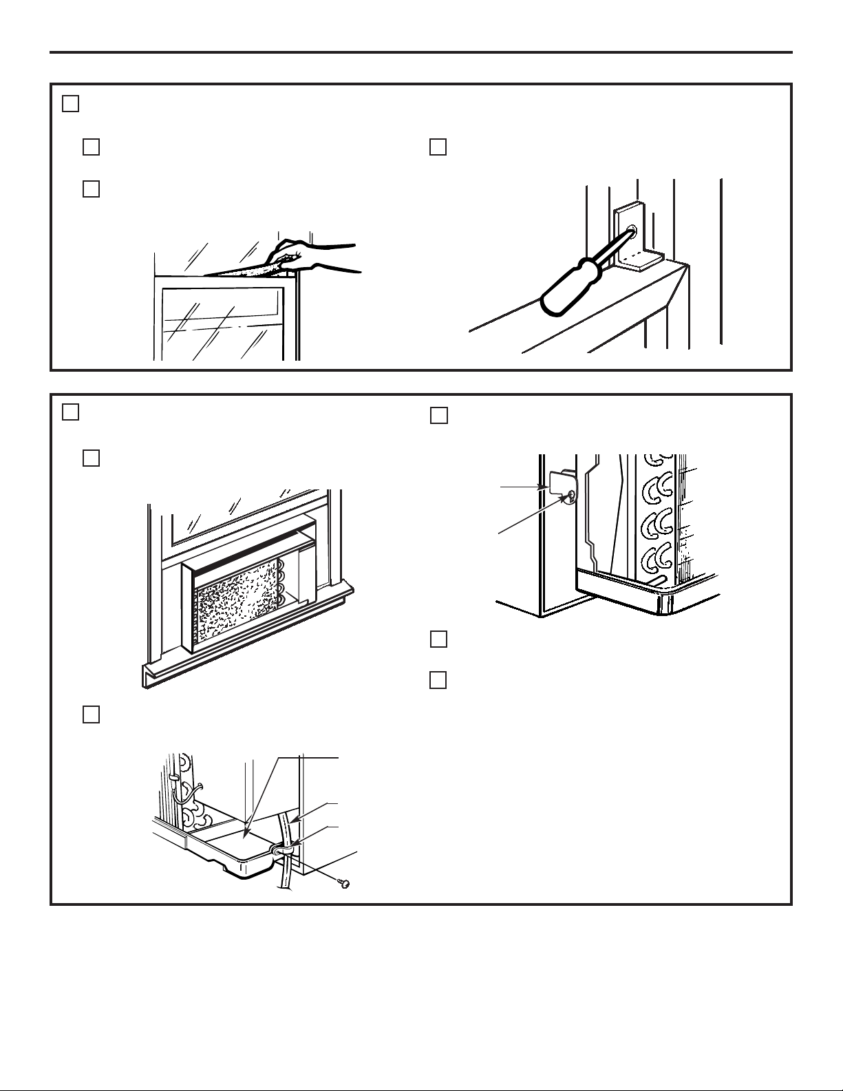
INSTALL CASE IN WINDOW
Peel off the backing from the bottom window
gasket.
Place the gasket on the stool and over the
brackets, even with the rear edge, sticky
side down.
Carefully slide the empty case into the window
until the holes in the case line up with the holes
in the panel angles.
NOTES:
• The case should have a 1/8″ minimum tilt toward
the outside.
• Be sure the seal gasket and panel gaskets remain
in position and do not roll with the case.
Lower the window so it fits behind the panel tabs.
Insert the 4 type A screws through the holes in the
case and into the panel angles, 2 on each side.
With the window closed, mark where the window
sash meets the case.
Peel off the backing from the case top gasket.
Hold on to the case, open the window and place
the gasket along the mark on the case.
Place the vinyl window gasket over the case top
gasket. Insert the panel tabs through the slits in
the gasket. Cut the gasket on each side to the width
of the window.
Close the window tightly on the vinyl gasket.
Bend the gasket forward to expose the panel tabs.
Drill pilot holes into the window sash.
Installation Instructions
20
WINDOW INSTALLATION—OPTIONAL (cont.)
7
A
B
C
D
E
F
G
H
I
Bottom window gasket
Case holes
Panel
tabs
Case
screws
Put the gasket on
top of the case
where the window
will close.
Panel tab
Vinyl window gasket
Attach the panel tab
to the window on each side
with a type D screw.
Page 21
Installation Instructions
21
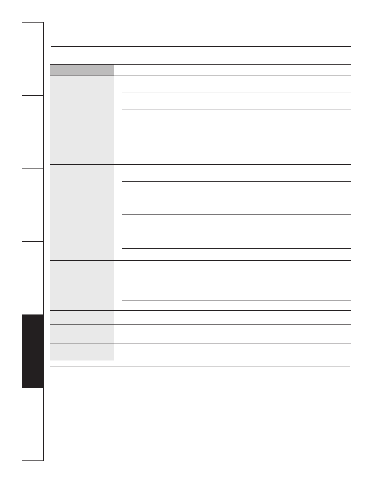
REPLACE AIR CONDITIONER
IN CASE
Carefully slide the air conditioner back into
the case.
Attach the power cord to the base pan with
the clamp.
Reinstall the locking plate with the tab behind
the wall case flange. Tighten the screw.
Reattach the front grille. An opening for the power
cord is on the bottom of the front grille.
Fill holes and cracks with caulking provided by
the installer
.
INSTALL WINDOW GASKET AND
LOCKING BRACKET
Cut the foam top window gasket to the window
width.
Stuff the foam between the glass and the window
to prevent air and insects from getting into the
room.
Attach the window locking bracket with
1 type E screw.
8
A
B
9
A
B
C
C
D
E
Clamp
Power cord
Base pan
Locking
plate
Tighten
screw
Page 22
Consumer Support Troubleshooting Tips Installation Instructions Care and Cleaning Operating Instructions Safety Instructions
22
Before you call for service…
Troubleshooting Tips: Save time and money! Review the chart below first and you may not need to call for service.
Normal Operating Sounds
■
You may hear a pinging noise caused by water
being picked up and thrown against the
condenser on rainy days or when the humidity
is high. This design feature helps remove moisture
and improve efficiency.
■
You may hear the thermostat click when the
compressor cycles on and off.
■
Water will collect in the base pan during high
humidity or on rainy days. The water may
overflow and drip from the outdoor side of
the unit.
■
The fan may run even when the compressor
does not.
Problem Possible Causes What To Do
Air conditioner The air conditioner • Make sure the air conditioner plug is pushed completely
does not start is unplugged. into the outlet.
The fuse is blown/circuit • Check the house fuse/circuit breaker box and replace
breaker is tripped. the fuse or reset the breaker.
Power failure. • If power failure occurs, turn the air conditioner OFF. When
power is restored, wait 3 minutes to restart the air conditioner
to prevent tripping of the compressor overload.
The current interrupter • Press the RESET button located on the power cord plug.
device is tripped.
• If the RESET button will not stay engaged, discontinue use
of the air conditioner and contact a qualified service
technician.
Air conditioner does Airflow is restricted. • Make sure there are no curtains, blinds or furniture blocking
not cool or heat (some the front of the air conditioner.
models) as it should
The temp control may • In COOL mode or HEAT mode (some models), press the
not be set correctly. DECREASE – pad.
The air filter is dirty. • Clean the filter at least every 30 days.
See the Operating Instructions section.
The room may have been hot. • When the air conditioner is first turned on, you need
to allow time for the room to cool down.
Cold air is escaping. • Check for open furnace registers and cold air returns.
• Make sure the air conditioner’s vent is in the closed position.
Cooling coils have iced up. • See “Air conditioner freezing up” below.
Air conditioner Ice blocks the airflow • Set the controls at HIGH FAN or HIGH COOL and set the
freezing up and stops the air conditioner thermostat to a higher temperature to allow the ice to melt.
from cooling the room.
The remote control is The batteries are inserted • Check the position of the batteries. They should be
not working incorrectly. inserted correctly.
The batteries may be dead. • Replace the batteries.
Water drips outside Hot, humid weather. • This is normal.
Water drips indoors The air conditioner is not • For proper water disposal, make sure the air conditioner
tilted to the outside. slants slightly from the case front to the rear.
Water collects in Moisture removed from air • This is normal for a short period in areas with little
base pan and drains into base pan. humidity; normal for a longer period in very humid areas.
Page 23

This warranty is extended to the original purchaser and any succeeding owner for products purchased
for home use within the USA and Canada. If the product is located in an area where service by a GE
Authorized Servicer is not available, you may be responsible for a trip charge or you may be required
to bring the product to an Authorized GE Service location for service. In Alaska, the warranty excludes
the cost of shipping or service calls to your home.
Some states do not allow the exclusion or limitation of incidental or consequential damages. This warranty
gives you specific legal rights, and you may also have other rights which vary from state to state. To know
what your legal rights are, consult your local or state consumer affairs office or your state’s Attorney
General.
Warrantor: General Electric Company. Louisville, KY 40225
23
Safety Instructions Operating Instructions Care and Cleaning Installation Instructions Troubleshooting Tips Consumer Support
Air Conditioner Warranty.
■ Service trips to your home to teach you how to use
the product.
■ Improper installation, delivery or maintenance. If you
have an installation problem, or if the air conditioner is
of improper cooling capacity for the intended use,
contact your dealer or installer. You are responsible for
providing adequate electrical connecting facilities.
■ Failure of the product resulting from modifications to
the product or due to unreasonable use including
failure to provide reasonable and necessary
maintenance.
■ In commercial locations labor necessary to move the
unit to a location where it is accessible for service by
an individual technician.
■ Replacement of house fuses or resetting of circuit
breakers.
■ Failure due to corrosion on models not corrosion-
protected.
■ Damage to the product caused by improper power
supply voltage, accident, fire, floods or acts of God.
■ Incidental or consequential damage caused by possible
defects with this air conditioner.
■ Damage caused after delivery.
■ Product not accessible to provide required service.
What GE Will Not Cover:
All warranty service provided by our Factory Service Centers,
or an authorized Customer Care
®
technician. To schedule service,
on-line visit us at GEAppliances.com, or call 800.GE.CARES
(800.432.2737). For service in Canada, contact Gordon Williams
Corp. at 1.888.209.0999. Please have serial number and model
number availa ble when calling for service.
Staple your receipt here.
Proof of the original purchase
date is needed to obtain
service under the warranty.
For The Period Of: GE Will Replace:
One Year Any part of the air conditioner which fails due to a defect in materials or workmanship.
From the date of the During this limited one-year warranty, GE will also provide, free of charge, all labor
original purchase and related service to replace the defective part.
Five Years Any part of the sealed refrigerating system (the compressor, condenser, evaporator
From the date of the and all connecting tubing) which fails due to a defect in materials or workmanship.
original purchase During this four-year limited additional warranty, GE will also provide, free of charge,
all labor and related service to replace the defective part.
EXCLUSION OF IMPLIED WARRANTIES—Your sole and exclusive remedy is product repair as provided in this Limited
Warranty. Any implied warranties, including the implied warranties of merchantability or fitness for a particular
purpose, are limited to one year or the shortest period allowed by law.
Page 24

Consumer Support.
GE Appliances Website
GEAppliances.com
Have a question or need assistance with your appliance? Try the GE Appliances Website 24 hours a day,
any day of the year! For greater convenience and faster service, you can now download Owner’s Manuals,
order parts or even schedule service on-line.
Schedule Service GEAppliances.com
Expert GE repair service is only one step away from your door. Get on-line and schedule your service at
your convenience any day of the year! Or call 800.GE.CARES (800.432.2737) during normal business hours.
Real Life Design Studio GEAppliances.com
GE supports the Universal Design concept—products, services and environments that can be used by
people of all ages, sizes and capabilities. We recognize the need to design for a wide range of physical and
mental abilities and impairments. For details of GE’s Universal Design applications, including kitchen design ideas
for people with disabilities, check out our Website today. For the hearing impaired, please call 800.TDD.GEAC
(800.833.4322).
Extended Warranties GEAppliances.com
Purchase a GE extended warranty and learn about special discounts that are available while your warranty
is still in effect. You can purchase it on-line anytime, or call 800.626.2224 during normal business hours.
GE Consumer Home Services will still be there after your warranty expires.
Parts and Accessories GEAppliances.com
Individuals qualified to service their own appliances can have parts or accessories sent directly to their homes
(VISA, MasterCard and Discover cards are accepted). Order on-line today, 24 hours every day or
by phone at 800.626.2002 during normal business hours.
Instructions contained in this manual cover procedures to be performed by any user. Other servicing
generally should be referred to qualified service personnel. Caution must be exercised, since improper
servicing may cause unsafe operation.
Contact Us GEAppliances.com
If you are not satisfied with the service you receive from GE, contact us on our Website with all the details
including your phone number, or write to: General Manager, Customer Relations
GE Appliances, Appliance Park
Louisville, KY 40225
Register Your Appliance GEAppliances.com
Register your new appliance on-line—at your convenience! Timely product registration will allow for
enhanced communication and prompt service under the terms of your warranty, should the need arise.
You may also mail in the pre-printed registration card included in the packing material.
Printed in China
Page 25

Instructions de sécurité . . . . . . . . 2, 3
Instructions
de fonctionnement . . . . . . . . . . . . . . .4–9
Entretien et nettoyage
Filtre à air . . . . . . . . . . . . . . . . . . . . . . . . . . . . . 11
Grille frontale . . . . . . . . . . . . . . . . . . . . . . . . . .10
Grille et boîtier . . . . . . . . . . . . . . . . . . . . . . . . . 10
Serpentins extérieurs . . . . . . . . . . . . . . . . . 10
Instructions de montage
Avant de commencer . . . . . . . . . . . . . .12, 13
Installation d’un modèle « J » dans
un logement mural existant . . . . . . . . . . .14
Installation à travers le mur—
Facultatif . . . . . . . . . . . . . . . . . . . . . . . . . . . . . . 15
Installation de fenêtre—en option
sur les modèles qui comportent
ce matériel . . . . . . . . . . . . . . . . . . . . . . . . 16–21
En cas de panne
Avant d’appeler le service . . . . . . . . . . . . . 22
Bruits normaux de
fonctionnement . . . . . . . . . . . . . . . . . . . . . . . 22
Soutien au consommateur
Garantie . . . . . . . . . . . . . . . . . . . . . . . . . . . . . . 23
Soutien au
consommateur . . . . . . . Couverture arrière
Transcrivez les numéros de modèle
et de série ici :
# de modèle ____________________
# de série ______________________
Trouvez ces numéros sur une étiquette
placée derrière la carrosserie côté
chambre, sur le plateau.
Conditionneur d’air
www.electromenagersge.ca
Manuel d’utilisation et
instructions d’installation
Rafraîchissement
AJCM 08, 10 ACD*
uniquement AJCM 10, 12 DCD*
AJCQ 06 LCD*
AJCQ 08, 10, 12 ACD*
AJCQ 09, 10, 12 DCD*
Réchauffement/
AJEM 12 DCD
rafraîchessment
AJEQ 06 LCD
AJEQ 08 ACD
AJEQ 09, 10, 12 DCD
En qualité de partenaire ENERGY STA R®,
GE a trouvé que ce produit rencontre
les directives d’ENERGY STA R®en matière
d’efficience énergétique.
*Produit avec l’etiquette ENERGY STA R
®
TINSEA568JBRZ 49-7597-2 06-09 JR
Page 26

AVERTISSEMENT! Risque
d’électrocution. Peut causer des blessures, voire
le décès. Cet appareil doit être mis à la terre
correctement. Ne coupez ou n’enlevez jamais la
broche de mise à la terre (la troisième broche de la
fiche) du cordon d’alimentation. Pour votre sécurité
personnelle, cet appareil doit être bien mis à la
terre.
■ Le cordon d’alimentation de cet appareil est
muni d’une fiche triphasée (mise à la terre)
qui correspond à une prise murale normale
triphasée, pour réduire le danger de secousse
électrique.
■ Faites vérifier la prise murale et le circuit
électrique par un électricien qualifié pour
vous assurer que la prise est bien à la terre.
■ Le cordon d’alimentation peut comprendre
un mécanisme d’interruption de courant.
Un bouton d’essai et de remise en marche est
fourni sur le boîtier de la prise. Vous devez
essayer le mécanisme périodiquement en
appuyant d’abord sur le bouton TEST (essai)
puis sur le bouton RESET (remise en marche).
Si le bouton TEST ne bascule pas ou si le
bouton RESET ne reste pas enfoncé, cessez
d’utiliser votre conditionneur d’air et appelez
un technicien de service qualifié.
■ Si vous avez une prise biphasée, vous êtes
personnellement responsable et obligé
de la faire remplacer par une prise murale
triphasée bien mise à la terre.
AVERTISSEMENT! Risque
d’électrocution. Peut causer des blessures,
voire le décès.
■ Vous devez toujours brancher le conditionneur
dans sa propre prise électrique, d’un voltage
qui correspond à la plaque signalétique. Cela
vous permettra d’obtenir le meilleur rendement
et empêchera la surcharge des circuits
électriques de la maison, qui risque
d’occasionner un danger d’incendie.
■ Consultez les Instructions de montage, section
des Exigences électriques, pour les exigences
de branchements électriques particuliers.
ALIMENTATION DE L’APPAREIL
AVERTISSEMENT! Risque
d’électrocution. Peut causer des blessures, voire le
décès. Pour votre sécurité, vous devez suivre les
instructions de ce manuel pour réduire les risques
d’incendie, de secousse électrique et de blessure.
■ N’utilisez cet appareil que pour son usage
prévu, tel que décrit dans le Manuel de
l’utilisateur.
■ Vous devez bien monter ce conditionneur,
conformément aux Instructions de montage,
avant de l’utiliser.
■ Ne débranchez jamais votre conditionneur en
tirant sur le cordon d’alimentation. Saisissez
fermement la fiche et sortez-la droit de sa prise.
■ Remplacez immédiatement tout cordon
d’alimentation abîmé ou endommagé. Un
cordon d’alimentation électrique endommagé
ne doit pas être réparé mais plutôt remplacé par
un autre cordon d’alimentation obtenu du
fabricant. N’utilisez pas un cordon d’alimentation
qui montre des fissures ou des signes d’abrasion
sur sa longueur ou encore près de la prise
ou du connecteur.
■ Éteignez et débranchez votre climatiseur avant
de procéder à une réparation ou un nettoyage.
REMARQUE : Nous vous recommandons
instamment de faire effectuer tout service
par un technicien qualifié.
■ Pour votre sécurité…ne rangez jamais ou
n’utilisez jamais des matériaux combustibles,
de l’essence ou d’autres vapeurs ou liquides
inflammables à proximité de cet appareil ou
de tout autre appareil électroménager.
■ Tous les conditionneurs contiennent des fluides
frigorigènes qui, en vertu de la loi fédérale,
doivent être retirés avant la mise au rebut de
l’appareil. Si vous vous débarrassez d’un vieil
appareil contenant des fluides frigorigènes,
renseignez-vous sur la façon de faire auprès
de l’entreprise qui s’occupe de la mise au rebut.
PRÉCAUTIONS DE SÉCURITÉ
2
RENSEIGNEMENTS IMPORTANTS EN MATIÈRE DE SÉCURITÉ.
LISEZ TOUTES LES INSTRUCTIONS AVANT USAGE.
CONSERVEZ CES INSTRUCTIONS
Soutien au
consommateur
En cas
de panne
Instructions de
montage
Entretien
et nettoyage
Instructions de
fonctionnement
Instructions
de sécurité
Page 27

3
AVERTISSEMENT! Risque
d’électrocution. Peut causer des blessures,
voire le décès.
■
Nous vous recommandons instamment
de ne pas utiliser de rallonge.
■
Si vous devez utiliser une rallonge, il faut
absolument qu’elle soit homologuée ACNOR,
calibre 14, triphasée à trois fils pour appareil
électroménager, munie d’une fiche et d’une
prise avec mise à la terre et que sa capacité
électrique soit de 15 ampères (minimum) et
125 volts.
■
N’UTILISEZ JAMAIS de rallonge avec
un modèle de 230/208 volts.
UTILISATION DE RALLONGES—
modèles de 115 volts uniquement
AVERTISSEMENT! Risque
d’électrocution. Peut causer des blessures,
voire le décès.
■
Nous sommes absolument opposés à
l’utilisation d’une fiche d’adaptation.
■
Si vous devez utiliser une fiche d’adaptation,
quand les codes locaux le permettent, vous
pouvez établir un contact temporaire avec
une prise murale biphasée bien mise à la
terre, en utilisant une fiche d’adaptation
homologuée UL en vente dans un grand
nombre de quincailleries.
■
La fente la plus grande de l’adaptateur doit
être alignée à la plus grande fente de la prise
murale pour obtenir une bonne polarité avec
le cordon d’alimentation.
■
Quand vous débranchez le cordon
d’alimentation de l’adaptateur, tenez
l’adaptateur en place en tirant la fiche du
cordon d’alimentation avec votre autre
main. Si vous ne le faites pas, vous casserez
probablement la broche de mise à la terre
de l’adaptateur.
■
Si la broche de mise à la terre de l’adaptateur
est cassée, N’UTILISEZ PAS le conditionneur
avant de bien le remettre à la terre.
■
Si vous fixez la broche de mise à la terre de
l’adaptateur à une vis du couvercle de la
prise murale, cela ne met pas à la terre
l’appareil, à moins que la vis soit en métal
et pas isolée et que la prise murale soit mise
à la terre par l’intermédiaire du câblage de
la maison. Vous devez faire vérifier le circuit
par un électricien qualifié pour vous assurer
que la prise est bien mise à la terre.
UTILISATION DE FICHES D’ADAPTATION—
modèles de 115 volts uniquement
LISEZ ET SUIVEZ SCRUPULEUSEMENT CES
INFORMATIONS DE SÉCURITÉ.
CONSERVEZ CES INSTRUCTIONS
(Les fiches d’adaptation sont interdites au Canada)
www.electromenagersge.ca
Instructions
de sécurité
Instructions de
fonctionnement
Entretien et
nettoyage
Instructions
de montage
En cas
de panne
Soutien au
consommateur
Page 28

4
■ Pour vous assurer d’un fonctionnement adéquat,
pointez la télécommande sur le récepteur de signal
du conditionneur.
■ Le rayon d’action du signal de la télécommande
s’étend jusqu’à 21 pieds (6,4 m).
■ Assurez-vous qu’aucun obstacle pouvant bloquer
le signal ne se trouve entre le conditionneur et
la télécommande.
■ Assurez-vous que les piles sont récentes et installées
correctement—voir la section Entretien et nettoyage.
Télécommande
ON/OFF (marche/arrêt)
Met le conditionneur en position de marche
ou d’arrêt.
Affichage
Affiche le réglage de température. Affiche les heures
lors du réglage de la minuterie.
MODE
Sur la télécommande, utilisez cette fonction pour
régler le conditionneur au mode COOL (frais)
ou FAN (ventilateur).
Sur les commandes du conditionneur, utilisez cette
fonction pour régler le mode COOL ou FAN
à la vitesse de ventilateur HIGH (haut), MED
(moyen) ou LOW (bas). Les témoins lumineux sur
les commandes du conditionneur indiquent le
mode et la vitesse du ventilateur sélectionnés.
TEMP Increase + /Decrease – Pads
(touches d’augmentation/diminution
de la température)
Utilisez cette fonction pour régler la température
lorsque l’appareil est en mode COOL.
Vitesses du ventilateur (FAN)
(télécommande seulement)
Utilisez cette fonction pour régler la vitesse
du ventilateur à LOW, MED ou HIGH.
TIMER (minuterie)
ON (marche) —Lorsque le conditionneur est
en position d’arrêt, il peut être réglé pour démarrer
automatiquement dans un délai d’une demi heure
à 24 heures à son réglage précédent. Chaque
effleurement augmente la durée d’une demi heure
jusqu’à 10, puis d’une heure jusqu’à 24.
Pour annuler la minuterie en position marche,
appuyez sur la touche ON (marche) jusqu’à
la disparition de l’heure affichée.
OFF (arrêt) —Quand le conditionneur est
en marche, vous pouvez le régler de manière
à ce qu’il s’arrête automatiquement au bout d’une
durée d’une demi heure à 24 heures. Chaque
effleurement augmente la durée d’une demi heure
jusqu’à 10, puis d’une heure jusqu’à 24.
Pour annuler la minuterie en position Arrêt,
appuyez sur la touche OFF (arrêt) jusqu’à
la disparition de l’heure affichée.
SLEEP (sommeil)
Pressez cette touche pour faire fonctionner
le conditionneur pendant 8 heures avant qu’il
retourne au réglage précédent automatiquement.
Lorsque la minuterie de sommeil est réglée,
la température sélectionnée augmentera
automatiquement de 2° F (1° C) après la deuxième
heure, puis de 1° F (0,5° C) par heure pour les deux
heures suivantes.
Pour annuler le mode de sommeil, enfoncez
la touche MODE ou la touche SLEEP (sommeil)
une deuxième fois.
Récepteur de signaux de la télécommande
REMARQUE :
Lorsque le conditionneur est allumé,
il démarre automatiquement avec les réglages
précédemment utilisés.
Commandes sur le conditionneur—
Modèles avec mode Cool (Climatisation) seulement
Télécommande
Les témoins lumineux à côté des touches à effleurement sur le tableau
de commande du conditionneur indiquent les réglages sélectionnés.
Commandes
L’aspect peut varier.
Commandes du conditionneur
Soutien au
consommateur
En cas
de panne
Instructions de
montage
Entretien
et nettoyage
Instructions de
fonctionnement
Instructions
de sécurité
Page 29

www.electromenagersge.ca
MODE CLIMATISATION (COOL)
Télécommande
1. Appuyez sur la touche COOL (frais).
2. Appuyez sur les touches LOW (bas), MED (moyen)
ou HIGH (haut) pour régler la vitesse
de ventilateur voulue.
3. Appuyez sur les touches INCREASE +/
DECREASE –pour régler la température voulue
entre 60° F (16° C) et 85° F (30° C) par incréments
de 1° F (0,5° C).
Tableau de commande
1. Appuyez sur la touche MODE jusqu’à ce que le
témoin lumineux de la fonction COOL soit allumé,
et jusqu’à ce que le témoin lumineux de la vitesse
de ventilateur voulue LOW, MED ou HIGH soit
aussi allumé.
2. Appuyez sur les touches INCREASE +/
DECREASE –pour régler la température voulue
entre 60° F (16° C) et 85° F (30° C) par incréments
de 1° F (0,5° C).
Un thermostat est utilisé pour maintenir la
température ambiante. Le compresseur effectuera
un cycle marche-arrêt pour garder la température
ambiante au niveau de confort choisi. Réglez le
thermostat à une valeur plus basse et l’air intérieur
se refroidira. Réglez le thermostat à une valeur plus
élevée et l’air intérieur se réchauffera.
REMARQUE : Si le conditionneur en position d’arrêt
est mis en position de marche alors qu’il est réglé
à COOL, il faudra environ 3 minutes pour démarrer
le compresseur et amorcer un refroidissement.
Instructions concernant la climatisation
Pour un refroidissement normal—Sélectionnez
le mode COOL et la vitesse de ventilateur HIGH
ou MED avec un réglage de température moyen.
Pour un refroidissement maximal—Sélectionnez
le mode COOL et la vitesse de ventilateur HIGH
avec un réglage de température plus bas.
Pour un refroidissement plus silencieux ou durant
la nuit—Sélectionnez le mode COOL et la vitesse
de ventilateur LOW avec un réglage de
température moyen.
REMARQUE : Si vous passez du mode COOL
au mode FAN ou à la position OFF (arrêt), attendez
au moins 3 minutes avant de revenir au mode
COOL.
MODE VENTILATEUR (FAN)
Utilisez le mode FAN (ventilateur) pour filtrer et faire
circuler l’air sans refroidissement. Étant donné
qu’un réglage en mode ventilateur seulement
n’entraîne pas de refroidissement, le réglage
de température ne sera pas affiché.
Télécommande
Appuyez sur la touche FAN. Appuyez sur les
touches LOW (bas), MED (moyen) ou HIGH (haut)
pour régler le ventilateur à la vitesse désirée.
Tableau de commande
Appuyez sur la touche MODE jusqu’à ce que le
témoin lumineux FAN soit allumé et jusqu’à ce
que le témoin lumineux LOW, MED ou HIGH
correspondant à la vitesse voulue soit aussi allumé.
5
Instructions
de sécurité
Instructions de
fonctionnement
Entretien et
nettoyage
Instructions
de montage
En cas
de panne
Soutien au
consommateur
Page 30

6
■ Pour vous assurer d’un fonctionnement adéquat,
pointez la télécommande sur le récepteur de signal
du conditionneur.
■ Le rayon d’action du signal de la télécommande
s’étend jusqu’à 21 pieds (6,4 m).
■ Assurez-vous qu’aucun obstacle pouvant bloquer
le signal ne se trouve entre le conditionneur et
la télécommande.
■ Assurez-vous que les piles sont récentes et installées
correctement—voir la section Entretien et nettoyage.
Télécommande
ON/OFF (marche/arrêt)
Met le conditionneur en position de marche
ou d’arrêt.
Affichage
Affiche le réglage de température. Affiche les heures
lors du réglage de la minuterie.
MODE
Sur les commandes du conditionneur, utilisez cette
fonction pour régler le mode COOL (frais), HEAT
(chaleur) ou FAN (ventilateur). Les témoins lumineux
sur les commandes du conditionneur indiquent
le mode sélectionné.
TEMP Increase + /Decrease – Pads
(Touches d’augmentation/Diminution
de la température)
Utilisez cette fonction pour régler la température
lorsque l’appareil est en mode COOL ou HEAT.
Vitesses du ventilateur (FAN)
(Télécommande seulement)
Utilisez cette fonction pour régler la vitesse
du ventilateur à LOW (bas) ou HIGH (haut). Les
témoins lumineux indiquent la vitesse sélectionnée.
TIMER (minuterie)
ON (marche)—Lorsque le conditionneur est en
position d’arrêt, il peut être réglé pour démarrer
automatiquement dans un délai d’une demi heure
à 24 heures à son réglage précédent. Chaque
effleurement augmente la durée d’une demi heure
jusqu’à 10, puis d’une heure jusqu’à 24.
Pour annuler la minuterie en position marche,
appuyez sur la touche ON (marche) jusqu’à la
disparition de l’heure affichée.
OFF (arrêt) —Quand le conditionneur est
en marche, vous pouvez le régler de manière
à ce qu’il s’arrête automatiquement au bout d’une
durée d’une demi heure à 24 heures. Chaque
effleurement augmente la durée d’une demi heure
jusqu’à 10, puis d’une heure jusqu’à 24.
Pour annuler la minuterie en position Arrêt,
appuyez sur la touche OFF (arrêt) jusqu’à la
disparition de l’heure affichée.
Récepteur de signaux de la télécommande
REMARQUE :
Lorsque le conditionneur est allumé,
il démarre automatiquement avec les réglages
précédemment utilisés.
Commandes sur le conditionneur—
Modèles avec modes Chauffage/Climatisation
Télécommande
Les témoins lumineux à côté des touches à effleurement sur le tableau
de commande du conditionneur indiquent les réglages sélectionnés.
Commandes
Commandes du conditionneur
L’aspect peut varier.
Soutien au
consommateur
En cas
de panne
Instructions de
montage
Entretien
et nettoyage
Instructions de
fonctionnement
Instructions
de sécurité
Page 31

www.electromenagersge.ca
MODE CLIMATISATION (COOL)
Télécommande
1. Appuyez sur la touche COOL (frais).
2. Appuyez sur les touches LOW (bas), MED (moyen)
ou HIGH (haut) pour régler la vitesse
de ventilateur voulue.
3. Appuyez sur les touches INCREASE +/
DECREASE –pour régler la température voulue
entre 60 °F (16 °C) et 85 °F (30 °C) par incréments
de 1 °F (0,5 °C).
Tableau de commande
1. Appuyez sur la touche MODE jusqu’à ce que le
témoin lumineux de la fonction COOL s’allume.
2. Appuyez sur la touche FAN (ventilateur) jusqu’à ce
que le témoin lumineux de la vitesse voulue HIGH
ou LOW s’allume.
3. Appuyez sur les touches INCREASE +/
DECREASE –pour régler la température voulue
entre 60 °F (16 °C) et 85 °F (30 °C) par incréments
de 1 °F (0,5 °C).
Un thermostat est utilisé pour maintenir la
température ambiante. Le compresseur effectuera
un cycle marche-arrêt pour garder la température
ambiante au niveau de confort choisi.
Réglez le thermostat à une valeur plus basse et l’air
intérieur se refroidira. Réglez le thermostat à une
valeur plus élevée et l’air intérieur se réchauffera.
REMARQUE : Si le conditionneur en position d’arrêt
est mis en position de marche alors qu’il est réglé
à COOL, il faudra environ 3 minutes pour démarrer
le compresseur et amorcer un refroidissement.
Instructions concernant la climatisation
Pour un refroidissement normal—Sélectionnez
le mode COOL et la vitesse de ventilateur HIGH
ou MED avec un réglage de température moyen.
Pour un refroidissement maximal—Sélectionnez
le mode COOL et la vitesse de ventilateur HIGH
avec un réglage de température plus bas.
Pour un refroidissement plus silencieux ou durant
la nuit—Sélectionnez le mode COOL et la vitesse
de ventilateur LOW avec un réglage de
température moyen.
REMARQUE : Il y a un délai de 3 minutes entre les
changements de réglage, par exemple de COOL
à OFF (arrêt) et retour à COOL.
VENTILATEUR (FAN)
Utilisez le mode FAN pour filtrer et faire circuler l’air
sans refroidissement ou chauffage. Étant donné
qu’un réglage en mode ventilateur seulement
n’entraîne ni refroidissement ni chauffage, le
réglage de température ne sera pas affiché.
Télécommande
Appuyez sur la touche FAN. Appuyez sur les
touches LOW (bas), MED (moyen) ou HIGH (haut)
pour régler le ventilateur à la vitesse désirée.
Tableau de commande
Appuyez sur la touche MODE jusqu’à ce que le
témoin lumineux FAN soit allumé et jusqu’à ce
que le témoin lumineux LOW, MED ou HIGH
correspondant à la vitesse voulue soit aussi allumé.
7
MODE CHAUFFAGE (HEAT)
Télécommande
1. Appuyez sur la touche HEAT (chaleur).
2. Appuyer sur la touche LOW (bas) ou HIGH (haut)
pour régler la vitesse de ventilateur voulue.
3. Appuyez sur les touches INCREASE +/
DECREASE
–
pour régler la température voulue
entre 60 °F (16 °C) et 85 °F (30 °C) par incréments
de 1 °F (0,5 °C).
Tableau de commande
1. Appuyez sur la touche MODE jusqu’à ce que le
témoin lumineux de la fonction HEAT s’allume.
2. Appuyez sur la touche FAN jusqu’à ce que le
témoin lumineux de la vitesse de ventilateur
voulue HIGH ou LOW s’allume.
3. Appuyez sur les touches INCREASE
+
/
DECREASE –pour régler la température voulue
entre 60 °F (16 °C) et 85 °F (30 °C) par incréments
de 1 °F (0,5 °C).
Un thermostat est utilisé pour maintenir la
température ambiante. Le compresseur effectuera
un cycle marche-arrêt pour garder la température
ambiante au niveau de confort choisi.
Réglez le thermostat à une valeur plus élevée et l’air
intérieur se réchauffera. Réglez le thermostat à une
valeur plus élevée et l’air intérieur se refroidira.
REMARQUE : Si le conditionneur en position d’arrêt
est mis en position de marche alors qu’il est réglé
à HEAT, il faudra environ 3 minutes pour démarrer
le compresseur et amorcer un réchauffement.
Instructions concernant le chauffage
Pour un réchauffement normal—Sélectionnez
le mode HEAT et la vitesse de ventilateur HIGH avec
un réglage de température moyen.
Pour un réchauffement maximal—Sélectionnez
le mode HEAT et la vitesse de ventilateur HIGH avec
un réglage de température plus élevé.
Pour un réchauffement plus silencieux ou durant
la nuit—Sélectionnez le mode HEAT et la vitesse de
ventilateur LOW avec un réglage de température
moyen.
REMARQUE : Il y a un délai de 3 minutes entre
les changements de réglage, par exemple de
HEAT à OFF (arrêt) et retour à HEAT.
Instructions
de sécurité
Instructions de
fonctionnement
Entretien et
nettoyage
Instructions
de montage
En cas
de panne
Soutien au
consommateur
Page 32

8
Au sujet des commandes sur le climatiseur.
Des persiennes
horizontales sur la
grille frontale vous
permettent de diriger
l’air vers le haut ou
le bas.
Retirez la grille
frontale pour régler
les persiennes
verticales de façon
à diriger l’air vers la
gauche ou la droite.
Commande d’évent
La commande d’évent est située derrière la grille
frontale sur le côté droit de la zone d’évacuation
d’air. Lorsque cette commande est réglée à
CLOSE, seul l’air à l’intérieur de la pièce est
climatisé et mis en circulation. Lorsqu’elle est
réglée à OPEN, l’évent permet un échange avec
l’air frais de l’extérieur.
Pour ouvrir ou fermer l’évent :
1. Retirer la grille frontale.
2. Enlevez la vis de la carte d’évent.
3. Enlevez la carte d’évent, retournez-la et
remplacez-la en trouvant le trou arrière dans la
carte sur le taquet d’emplacement à l’intérieur de
la décharge d’air et en rattachant la vis à l’avant.
Direction de l’air
Trou d’emplacement
Trou de vis
Position OUVERTE (extrémité de
la maille vers l’arrière)
Position FERMÉE (extrémité de
la maille vers l’avant)
Trou d’emplacement
Trou de vis
L’appareil quitte l’usine en position fermée.
Aucune fonction
(réservé pour usage futur)
Commandes auxiliaires – Commutateurs DIP (l’emplacement varie selon le modèle)
Les commutateurs DIP auxiliaires sont situés
à l’arrière de la carrosserie, dans la pièce – tel
qu’indiqué sur cette illustration.
Le propriétaire est responsable
de vérifier les commutateurs
et de s’assurer qu’ils sont
en bonne position.
Fonctionnement cyclique/continu du ventilateur –
Chauffage (sur certains modèles)
Classe 2 (sur certains modèles)
Fonctionnement cyclique/continu du ventilateur – Refroidissement
Quand ce commutateur est branché (UP) (haut), le ventilateur
intérieur se met en marche et s’arrête avec le compresseur.
Quand ce commutateur est débranché (DOWN) (bas), le
ventilateur intérieur fonctionne continuellement. Le réglage
par défaut est la position basse (continuellement).
Fonctionnement cyclique/continu du ventilateur – Chauffage (sur certains modèles)
Lorsque ce commutateur est activé (UP) (haut), le ventilateur
intérieur peut fonctionner continuellement en mode
chauffage. Lorsqu’il est désactivé (DOWN) (bas), le ventilateur
intérieur peut effectuer des cycles entre la marche et l’arrêt
(on/off). Le réglage par défaut est la position basse (cyclique).
Classe 2 – Thermostat à distance (sur certains modèles)
Quand ce commutateur est branché (UP) (haut), l’appareil est
contrôlé par un thermostat mural avec commande à distance
de classe 2. Les commandes de l’appareil sont hors service.
Le réglage par défaut est la position basse (désactivé).
Fonctionnement cyclique/continu du ventilateur –
Refroidissement
Fonctionnement cyclique/continu du
ventilateur – Chauffage (sur certains modèles)
Classe 2 (sur certains modèles)
Fonctionnement cyclique/continu du ventilateur –
Refroidissement
Soutien au
consommateur
En cas
de panne
Instructions de
montage
Entretien
et nettoyage
Instructions de
fonctionnement
Instructions
de sécurité
Page 33

9
www.electromenagersge.ca
Une fois raccordé, l’appareil sera contrôlé par
un thermostat à distance.
REMARQUE : Le commutateur numéro 3 doit être
activé (position haute) pour activer le thermostat
à distance. (Voir les instructions d’installation
fournies avec le thermostat à distance.)
IMPORTANT :
Les raccordements du thermostat procurent
un courant de 24 VCA seulement.
Si vous utilisez un thermostat mural
numérique/électronique, assurez-vous qu’il est
compatible avec un signal de 24 VCA. Consultez
les instructions d’installation du thermostat mural.
AVIS :
L’endommagement du thermostat mural
ou de l’électronique peut résulter de raccordements
incorrects. Une attention spéciale doit être apportée
au raccordement des fils. Aucun circuit ne doit être
raccordé à une tension secteur. Isolez de la tension
secteur tous les fils dans le bâtiment.
Bornes de raccordement du thermostat à distance - Classe 2 (sur certains modèles)
Les commandes sont situées sous le couvercle
de plastique, derrière la grille frontale.
Enlevez la grille frontale. Consultez la rubrique
sur la grille frontale dans la section Entretien
et nettoyage.
Enlevez les vis qui fixent le couvercle
de plastique au-dessus des connexions
de câblage. Mettez les vis et le couvercle
de côté.
Pour faire les raccordements, insérez les fils
dans le bas des bornes et vissez les vis
fermement.
Une fois terminés les raccordements voulus,
replacez le couvercle de plastique et la grille
frontale.
Le propriétaire est responsable de faire tous les
raccordements et de régler les commutateurs DIP
appropriés.
2
3
4
1
Emplacement
des bornes
de raccordement
sous la grille
frontale
Instructions
de sécurité
Instructions de
fonctionnement
Entretien et
nettoyage
Instructions
de montage
En cas
de panne
Soutien au
consommateur
Rouge – 24 V AC seulement
Vert – ventilateur vitesse réduite
Vert – ventilateur vitesse élevée
Jaune – Compresseur
Blanc – Chauffage
Commun – Terre
Page 34

Entretien et nettoyage du conditionneur.
La grille frontale peut être enlevée pour nettoyer
en profondeur et repérer les numéros de modèle
et de série à l’avant du plateau.
Pour retirer :
1. Tirez sur le filtre pour le dégager.
2. Enlevez les deux vis de la grille.
3. Dégagez la grille du bas et soulevez-la à partir
des languettes situées sur le dessus du boîtier.
Pour replacer :
Placez les languettes sur la grille frontale vis-à-vis
des languettes sur le devant du boîtier et mettez-les
en place en exerçant une pression.
Replacez les vis et le filtre.
Grille frontale
Serpentins extérieurs
Les serpentins situés du côté extérieur
du conditionneur doivent être vérifiés
régulièrement. S’ils sont obstrués par de la saleté
ou de la suie, il est possible de les faire nettoyer
à la vapeur par des professionnels en passant
par votre Centre de services GE.
Grille et boîtier
Éteignez le conditionneur et retirez la fiche
d’alimentation électrique de la prise murale
avant le nettoyage. Pour nettoyer, utilisez de
l’eau et un détergent doux. N’utilisez jamais
d’agent de blanchiment ou d’abrasif.
10
Sur certaines
modèles
Sur certaines
modèles
Grille
Languette
Languette
Grille
Soutien au
consommateur
En cas
de panne
Instructions de
montage
Entretien
et nettoyage
Instructions de
fonctionnement
Instructions
de sécurité
Page 35

www.electromenagersge.ca
Enlevez le couvercle du logement des piles
en le faisant glisser dans le sens de la flèche.
Insérez les nouvelles piles en vous assurant
que les pôles (+) et (-) des piles sont orientés
dans la bonne direction.
Remettez le couvercle en le faisant glisser
en place.
REMARQUE :
■ Utilisez 2 piles « AAA » (1,5 volt). N’employez
pas de piles rechargeables.
■ Retirez les piles de la télécommande si vous
ne prévoyez pas utiliser le système sur une
longue période de temps.
3
2
1
Pour conserver un rendement optimal, nettoyez le filtre au moins tous les 30 jours.
Comment insérer les piles dans la télécommande
Filtre à air
Éteignez le conditionneur avant le nettoyage.
La mesure la plus utile que vous pouvez prendre
pour entretenir votre conditionneur est de nettoyer
le filtre au moins tous les 30 jours. Un filtre obstrué
réduit l’efficacité de la climatisation, du chauffage
et de la ventilation.
Le nettoyage régulier du filtre à air :
■ Diminue le coût de fonctionnement;
■ Économise l’énergie;
■ Prévient l’obstruction des serpentins
de l’échangeur de chaleur;
■ Réduit le risque de défectuosités précoces.
Pour nettoyer le filtre à air :
■ Enlevez les particules grossières avec l’aspirateur.
■ Faites circuler de l’eau à travers le filtre.
■ Séchez à fond avant de le remettre en place.
Pour retirer le filtre à air, sur certaines modèles :
Tirez soigneusement la languette vers l’avant
et le haut pour la dégager.
Pour retirer le filtre à air, sur certaines modèles :
Tirer vers le bas.
Pour remettre le filtre à air en place :
Replacez le filtre propre en le poussant en place.
AVIS : Ne faites pas fonctionner le
conditionneur si le filtre n’est pas en place.
Le filtre doit être remplacé immédiatement
s’il est tordu ou endommagé.
Le fonctionnement de l’appareil avec un filtre
endommagé ou mal placé permet à la saleté
et la poussière d’atteindre les serpentins intérieurs
et réduit le rendement de l’appareil et l’efficacité de
la climatisation, du chauffage et de la ventilation.
Vous pouvez vous procurer des filtres de
remplacement auprès de votre vendeur, votre
revendeur GE, votre Centre de services et pièces
GE ou de réparateurs Customer Care®autorisés.
Filtre encrassé – Requiert
un nettoyage
Filtre obstrué – Réduit
considérablement le
climatisation, le chauffage
et la ventilation.
FRONT
FRONT
11
Instructions
de sécurité
Instructions de
fonctionnement
Entretien et
nettoyage
Instructions
de montage
En cas
de panne
Soutien au
consommateur
Page 36

Questions? Composez le 1.800.361.3400 ou visitez notre site web à : www.electromenagersge.ca
Instructions
Conditionneur
de montage
d’air
12
EXIGENCES EN MATIÈRE
D’ALIMENTATION ÉLECTRIQUE
AVERTISSEMENT! Risque d’électrocution.
Peut causer des blessures, voire le décès. Cet appareil doit
être mis à la terre correctement. En présence d’une prise
murale à 2 trous, vous avez la responsabilité et l’obligation
de la faire remplacer par une prise à 3 trous.
Certains modèles nécessitent une prise mise à
la terre de 115/120 volts c.a. 60 Hz, protégée par
un disjoncteur ou un fusible à fusion temporisé
de 15 amp.
La fiche triphasée réduit le danger de secousse électrique.
Si la prise murale que vous allez utiliser n’est qu’une prise
biphasée, vous êtes responsable de la faire remplacer par
une prise murale triphasée bien mise à la terre.
N’enlevez, ne coupez ou n’ôtez jamais la troisième broche
(de mise à la terre) du cordon d’alimentation.
Ne changez jamais la fiche du cordon d’alimentation
de ce conditionneur.
Un câblage de la maison en aluminium peut occasionner
des problèmes particuliers—consultez un électricien qualifié.
AVANT DE COMMENCER
Veuillez lire toutes ces instructions
attentivement.
•
IMPORTANT — Conservez ces instructions
à l’usage de l’inspecteur local.
•
IMPORTANT — Respectez tous les codes
et les ordonnances en vigueur.
• Note au monteur – Conservez le Manuel
du propriétaire.
• Note au consommateur – Conservez ces instructions
pour consultation ultérieure.
• Niveau de compétence – L’installation de cet appareil
exige des compétences de base en mécanique.
• Temps d’exécution – Environ 1 heure
• Nous recommandons que l’installation de ce produit
soit effectuée par deux personnes.
• La responsabilité de l’exactitude de l’installation
incombe à l’installateur.
• La garantie ne couvre pas les défectuosités du produit
causées par une installation inadéquate.
EXIGENCES EN MATIÈRE
D’ALIMENTATION ÉLECTRIQUE (suite)
Certains modèles nécessitent une alimentation
de 230/208 volts c.a., protégée par un disjoncteur
ou un fusible à fusion temporisé. Vous devez monter
ces modèles sur leur propre circuit dérivé pour éviter
la surcharge des circuits de câblage de la maison ou
de l’appartement, qui peut occasionner un danger
d’incendie par surchauffe des câbles.
IMPORTANT! GE recommande fortement
de remplacer l’ancien logement mural par un nouveau
de marque GE. Si vous décidez de garder le logement
mural existant, vous pourriez avoir besoin d’une trousse
d’adaptation pour obtenir un rendement adéquat.
Si vous n’utilisez PAS de trousse, vous risquez d’obtenir
un rendement médiocre ou une défaillance du produit,
ce qui n’est pas couvert par la garantie GE.
DÉTERMINATION DE LA TROUSSE
D’ADAPTATION DU MODÈLE « J »
Les conditionneurs de modèle « J » peuvent convenir à des
logements muraux existants. Cependant, il requièrent souvent
une trousse pour adapter adéquatement le logement au
conditionneur d’air GE. Répondez aux questions suivantes
et consultez le tableau de la page suivante pour déterminer
la trousse appropriée.
Quelle marque de conditionneur d’air allez-vous
remplacer ?
Quelles sont les dimensions du logement mural
présentement utilisé ?
Quel est le numéro de modèle du châssis présentement
utilisé ? Quel est le numéro (ou le type) de modèle
du logement mural présentement utilisé ?
Souvent, la trousse d’adaptation du modèle « J »
s’appliquera à un modèle de série d’une autre marque
ou à un millésime spécifique. Dans ces cas, vous avez
besoin du numéro de modèle du châssis et/ou du numéro
du logement ou du « type » pour déterminer la trousse
d’adaptation appropriée.
Quel type de grille extérieure est utilisée avec le logement
mural existant ?
Une grille ornementale peut être rattachée au logement
mural pour améliorer l’aspect extérieur du bâtiment.
Une grille personnalisée peut accompagner le logement
mural du modèle « J » à condition d’utiliser une trousse
d’adaptation pour assurer une ventilation adéquate.
A
B
C
D
Page 37

13
NUMÉROS DE TROUSSES GE
Le cordon d’alimentation peut comprendre
un mécanisme d’interruption de courant. Un bouton
d’essai et de remise en marche est fourni sur le boîtier
de la prise. Vous devez essayer le mécanisme
périodiquement en appuyant d’abord sur le bouton
TEST (essai) puis sur le bouton RESET (remise en marche).
Si le bouton TEST ne bascule pas ou si le bouton
RESET ne reste pas enfoncé, cessez d’utiliser votre
conditionneur d’air et appelez un technicien de service
qualifié.
Instructions de montage
UTILISEZ LE
NUMÉRO DE
TROUSSE GE : POUR : DESCRIPTION:
RAB46A, 47A Utilisez ces trousses pour Logement mural standard pour châssis modèle « J ». Grille
& 48A tous les modèles GE et les extérieure RAG13 en aluminium estampé incluse. Enlevez
autres marques non listées et remplacez le logement existant.
RAK65A1 Tous les modèles GE Trousse pour installation dans fenêtre
RAK56A100 GE RAB13, 14 & 15 Convient à tous les logements muraux GE de 26 po L x 18 po H
(Châssis ACLB & RCL) x 24 po P
RAK1072 Hotpoint ACXB10 & 11 Adapte un ancien logement Hotpoint à un châssis de modèle « J ».
(Châssis ACTB) Convient aux logements muraux Hotpoint de 25
3
⁄4 po L x 167⁄8 po H
x 185⁄8 po P
RAK1082 Whirlpool Type 23W Adapte un logement mural Whirlpool à un châssis de modèle « J ».
Logement mural Convient aux logements muraux Whirlpool de 25
7
⁄8 po L x 161⁄2 po H
x 231⁄8 po P
RAK1102 GE RAB30 Adapte un logement mural GE à un châssis de modèle « J ».
(Modèles « F ») Convient au logement mural RAB 30 de 26 po L x 18 po H x 24 po P
RAK123A64 Logement mural Adapte le logement mural Fedders au châssis du modèle « J ».
Fedders « A » Convient aux logements muraux Fedders de 27 po L x 16
3
⁄4 po H
x 163⁄4 po P
RAK126 Logement mural Adapte le logement mural Westinghouse au châssis du modèle
Westinghouse « J ». Convient aux logements muraux Westinghouse 25
7
⁄8 po L
(Type 2626D73H01) x 157⁄16 po H x 16 po P
RAB46, 47 & 48 Utilisez ces trousses pour Logement mural standard pour le châssis du modèle « J ». Grille
toutes les marques qui extérieure RAG13 en aluminium matricée comprise. Retirez
n’apparaissent pas dans le logement existant et remplacez-le.
cette liste.
RAK690 RAB36, 37, 38, 46, 47 ou 48 Si vous mettez une grille extérieure ornementale personnalisée,
(Châssis « J ») utilisez cette trousse pour obtenir une ventilation adéquate.
RAG13 RAB36, 37, 38, 46, 47 ou 48 Grille extérieure en aluminium standard (comprise avec les
(Châssis « J ») logements muraux RAB46, 47 et 48)
RAG14E RAB36, 37, 38, 46, 47 ou 48 Grille extérieure ornementale à persiennes
(Châssis « J »)
OUTILS DONT VOUS POUVEZ AVOIR BESOIN
Clé anglaise
Niveau
Tournevis à tête Phillips
Scie à main ou scie sauteuse
Perceuse
Crayon
Mètre à ruban ou ridge
Scissors ou couteau
Veuillez lire toutes ces instructions attentivement.
Page 38

Instructions de montage
RETIREZ LA PLAQUE DE VERROUILLAGE
SUR LE CÔTÉ GAUCHE AVANT
1
RÉINSTALLEZ LA PLAQUE DE
VERROUILLAGE EN PLAÇANT
LA LANGUETTE DERRIÈRE LE REBORD
DU LOGEMENT MURAL
Plaque de
verrouillage
Enlevez la vis
INSTALLATION D’UN MODÈLE « J » DANS UN LOGEMENT MURAL EXISTANT
Veuillez lire toutes ces instructions attentivement.
À L’INTÉRIEUR DU CONDITIONNEUR,
RETIREZ TOUS LES COUSSINETS
DE PROTECTION (SI APPLICABLE) SITUÉ
À CÔTÉ DU COMPRESSEUR
GLISSEZ DÉLICATEMENT LE
CONDITIONNEUR DANS LE LOGEMENT
Assurez-vous que la tubulure de l’appareil n’entre
pas en contact avec le logement mural et que
ce dernier est installé correctement.
2
3
FIXEZ LA GRILLE FRONTALE
Une ouverture pour le cordon d’alimentation
se trouve dans le bas de la grille frontale.
FIXEZ LE CORDON D’ALIMENTATION
AU PLATEAU À L’AIDE D’UNE AGRAFE
Agrafe
Cordon
d’alimentation
Plateau du fond
4
5
6
14
Enlevez les
coussinets
de protection
(si applicable)
Page 39

Instructions de montage
PRÉPARATION DE L’OUVERTURE
DANS LE MUR
Assurez-vous qu’une prise murale se trouve
à proximité de l’ouverture ou installez-en une.
La longueur du cordon des modèles 115 volts
est 72 po (1,8 m) à droite et 47 po (1,2 m) à gauche.
Dans le cas des modèles 230/208 volts, la longueur
du cordon est 65 po (1,65 m) à droite et 39 po (1,0 m)
à gauche.
1
INSTALLATION À TRAVERS LE MUR
Veuillez lire toutes ces instructions attentivement.
SUPPORT DU CONDITIONNEUR
Le logement mural du conditionneur doit
être installé en excédant le mur intérieur ou extérieur
d’au moins 1/4 po (6,4 mm).
Les côtés finis de l’ouverture doivent être des
éléments de charpente du mur.
Linteau – Pour les murs de maçonnerie, utilisez
un linteau pour supporter les briques ou les blocs
au-dessus de l’ouverture. Le logement mural
ne doit pas se substituer au linteau.
Solin – Installez un solin (garniture de gouttière)
de la manière illustrée pour empêcher l’eau
de dégoutter à l’intérieur du mur et sur l’extérieur
du bâtiment.
2
Moulure
(s’il y a lieu)
Panneau
de plâtre
Calfeutrage
(au-dessus
et en-dessous
du solin)
Solin (garniture
de gouttière)
Prolongement minimum
de 1/4 po (6,4 mm)
à partir de la moulure
Intérieur
de la pièce
Parement
de briques
Cornière
de linteau
(s’il y a lieu)
Calfeutrage
(sur les 4 côtés,
à l’extérieur
et l’intérieur
du logement)
SUPPORT DU CONDITIONNEUR
Le mortier entre le logement et la brique autour
du logement peut être creusé à 45° pour améliorer
le calfeutrage.
3
Calfeutrage
Dessus du logement
Intérieur
Extérieur
Mortier
creusé
15
Page 40

16
Instructions de montage
INSTALLATION DE FENÊTRE (EN OPTION)
AVERTISSEMENT! Risque de blessures. L’installation doit être conforme à ces directives.
Nécessite les trousses d’accessoires en option RAK65A1 et manchon mural RAB46A, 47A ou 48A
Lisez toutes ces instructions attentivement.
Conditionneur d’air
Type C (peintes) (6)
Type D (2)
Type E (4)
Grande rondelle (2)
Boulon de réglage (2)
Contre-écrou (2)
Agrafe d’écartement (2)
Quincaillerie pour la ferrure
de support
Type A (9)
Type B (2)
Ferrure
de support
de seuil (2)
2 angles
(côtés gauche
et droit)
Joint
d’étanchéité
de la paroi
latérale du
logement (2)
Bride à
ressort (4)
Ferrure
de verrouillage
de la fenêtre
Joint d’étanchéité
en vinyle de la fenêtre
Joint d’étanchéité inférieur de la fenêtre
Panneaux
de fermeture
Découpez
les panneaux
et jetez la
partie centrale
Joint d’étanchéité de la paroi
supérieure du logement
Joint d’étanchéité
supérieur en mousse
de la fenêtre
B
Côté
droit
A
Côté
gauche
(les trous sont du côté gauche)
(les trous sont du côté droit)
INSTRUCTIONS RELATIVES À LA FENÊTRE
• Ces instructions s’appliquent aux fenêtres à guillotine
à deux châssis mobiles. Elles devront être adaptées pour
les autres types de fenêtres.
• Le conditionneur peut être monté sans les panneaux
accordéons si la fenêtre est étroite. Voyez les dimensions
de l’ouverture de fenêtre dans l’illustration à droite.
• Toute la ferrure de montage doit être fixée solidement
sur le bois, la maçonnerie ou le métal.
• La prise d’alimentation électrique doit se trouver dans
la portée du cordon d’alimentation.
1
Les dimensions de l’ouverture de fenêtre s’appliquent
aux fenêtres à guillotine à deux châssis mobiles.
17 po min.
31 po à 43 po
(avec panneaux de fermeture)
26
1
⁄4 po min. (sans panneaux de fermeture)
Page 41

17
INSTRUCTIONS RELATIVES
À LA CONTRE-FENÊTRE
Le cadre de la contre-fenêtre empêche le
conditionneur de pencher vers l’extérieur et donc
de se drainer adéquatement. Pour régler ce problème,
fixez une pièce de bois sur le rebord de fenêtre.
PIÈCES DE BOIS
LARGEUR : 2 po
LONGUEUR : Suffisamment longue pour se loger
à l’intérieur du cadre de fenêtre.
ÉPAISSEUR : Pour déterminer l’épaisseur, placez une pièce
de bois sur le rebord de la fenêtre de façon à ce que
la pièce soit 1/2 po plus élevée que le dessus du cadre
de la contre-fenêtre.
Fixez solidement à l’aide des clous ou des vis fournies
par l’installateur.
2
1/2 po plus
élevé que
le cadre
Cadre de la
contre-fenêtre
Bois
Rebord
Seuil
RETIREZ LE CONDITIONNEUR DE SON
LOGEMENT
Retirez la grille frontale. Consultez la section
Entretien et nettoyage.
Trouvez la plaque de verrouillage située du côté
avant gauche.
Enlevez la vis et la plaque de verrouillage pour
déverrouiller le conditionneur.
Retirez et jetez la vis située à l’arrière du
conditionneur pour permettre de dégager
le conditionneur de son logement.
Tirez les coins inférieurs du conditionneur
et faites-le glisser à l’extérieur du logement.
Enlevez tous les coussinets de protection
(si applicable) situé près du compresseur
à l’intérieur du conditionneur.
Enlevez la grille arrière fixée avec du ruban derrière
le logement. Enlevez le paquet de vis attaché avec
du ruban à l’arrière de la grille. En la tenant à un angle
de 45°, insérez la grille dans les agrafes situées dans
la partie supérieure du logement et poussez sur le bas
de la grille pour la mettre en place. Maintenez une
légère pression vers le haut de la grille jusqu’à ce
qu’elle se loge contre la partie inférieure du logement.
3
A
B
C
Plaque de
verrouillage
Retirez la vis
D
Retirez la vis
E
F
Si vous fixez la grille
depuis l’extérieur du
logement, utilisez deux
vis longues.
Si la grille est fixée depuis
l’intérieur du boîtier,
utilisez 2 vis courtes.
G
Agrafes
Insérez les deux vis longues
depuis l’extérieur
Insérez les deux vis courtes
depuis l’intérieur
Instructions de montage
Enlevez les
coussinets
de protection
(si applicable)
Page 42

INSTALLATION DE FENÊTRE (EN OPTION) (suite)
18
Instructions de montage
INSTALLEZ LES SUPPORTS DE SEUIL
Fixez les supports de seuil. Ne serrez pas
complètement les vis de montage de l’agrafe
d’écartement pour l’instant.
Avant de fixer les supports de seuil, placez-les
sur le rebord de la fenêtre. Placez l’agrafe
d’écartement le plus près possible du point
le plus extérieur du seuil. Serrez les vis de montage
de l’agrafe d’écartement.
Vissez les boulons et serrez les contre-écrous
de façon à mettre les supports de seuil de niveau
ou inclinés de 1/8 po vers l’extérieur. Alignez l’encoche
en « V » sur les marques tracées à 12
3
⁄8 po. Percez
des avant-trous et fixez les supports de seuil.
REMARQUES :
• Dans le cas d’un seuil étroit, l’espace peut s’avérer
insuffisant pour utiliser un contre-écrou.
• Un seuil profondément décalé peut exiger l’utilisation
d’un boulon de réglage plus long que le boulon à tête
hexagonale standard fourni.
• Pour empêcher le boulon de s’enfoncer dans un seuil
en bois, utilisez une rondelle de grand format entre
la tête du boulon et le seuil.
PRÉPAREZ LA FENÊTRE
Tracez la ligne de centre du rebord de fenêtre.
Mesurez 13
3
⁄8 po de chaque côté de la ligne
de centre pour tracer la position des panneaux.
Mesurez 12
3
⁄8 po de chaque côté de la ligne de centre
pour déterminer la position des ferrures de support
de seuil.
4
A
B
5
A
B
C
Support de seuil
Seuil standard
Seuil étroit
Seuil décalé (comme la brique ou la pierre)
Agrafe d’écartement
Agrafe
d’écartement
Type B
Type E
Vis de montage de l’agrafe
d’écartement Type (A)
Contre-écrou
Support
de seuil
Boulon de réglage
Grande rondelle
(pour seuils en bois)
Rebord
Encoche
en « V »
du support
Les vis sont en place
Seuil
Boulon
Rebord
Seuil
133⁄8 po
Ligne de centre
Rebord
Seuil
Extérior
Extérior
Intérior
Intérior
133⁄8 po
123⁄8 po
123⁄8 po
Ligne de centre
Extérior
Intérior
Page 43

MESUREZ, COUPEZ ET INSTALLEZ LES
PANNEAUX DE FERMETURE
De chaque côté (A et B), mesurez la distance entre
la marque du panneau (voir Préparez la fenêtre) et
l’intérieur du rail de la fenêtre.
Tracez les distances A et B de chaque côté
de la pièce à découper. Coupez les panneaux
et jetez le morceau du centre. Remarquez
la position des encoches.
Assemblez les composants des panneaux.
Enlevez le doublage en papier du joint d’étanchéité
de la paroi latérale du boîtier et fixez le joint
sur l’angle. Poussez une pointe de crayon à travers
les joints pour localiser les trous des angles.
Montez les panneaux dans la fenêtre. Placez les brides
à ressort à 3 po du haut et du bas des panneaux.
Pliez et poussez les brides pour les loger dans les rails
de la fenêtre et insérez la languette dans le support
de seuil.
19
Instructions de montage
6
A
B
C
D
Seuil
A
Rail de la fenêtre
Largeur du
conditionneur
(marques des panneaux))
Côté
gauche
B
Côté
droit
133⁄8 po 133⁄8 po
BA
Joint
d’étanchéité
Joint
d’étanchéité
Angle
Panneau
Languette
Type C
(vis peintes)
Angle
Insérez la languette
dans le support
de seuil
Panneaux
de fermeture
Découpez les
panneaux et
jetez la partie
centrale
Côté
droit
Côté
gauche
(les trous sont du côté gauche)
(les trous sont du côté droit)
3 po
Extérior
Intérior
Page 44

INSTALLATION DE FENÊTRE (EN OPTION) (suite)
20
Instructions de montage
MONTEZ LE LOGEMENT
DANS LA FENÊTRE
Enlevez le doublage en papier du joint d’étanchéité
inférieur de la fenêtre.
Placez le joint d’étanchéité sur le rebord de la
fenêtre et par-dessus les supports, à égalité avec
le bord arrière, surface adhésive vers le bas.
Faites délicatement glisser le logement vide dans
la fenêtre jusqu’à ce que les trous du logement
s’alignent sur les trous des angles des panneaux.
REMARQUE :
• Le logement devrait avoir une inclinaison minimale
de 1/8 po vers l’extérieur.
• Assurez-vous que les joints d’étanchéité demeurent
en place et ne roulent pas avec le boîtier.
Baissez la fenêtre pour qu’elle repose derrière
les languettes des panneaux. Insérez les quatre
(4) vis de type A à travers les trous du logement
et les trous des angles, deux (2) de chaque côté.
La fenêtre étant fermée, marquez l’endroit
où le châssis de la fenêtre entre en contact avec
le logement du conditionneur.
Enlevez le doublage en papier du joint d’étanchéité
de la paroi supérieure du logement.
Tenez bien le logement, ouvrez la fenêtre et placez
le joint d’étanchéité le long de la marque tracée
sur le logement.
Placez le joint d’étanchéité en vinyle de la fenêtre
par-dessus le joint d’étanchéité de la paroi supérieure
du logement. Insérez les languettes des panneaux
dans les fentes du joint d’étanchéité. Coupez le joint
de chaque côté à la largeur de la fenêtre.
Fermez la fenêtre fermement sur le joint d’étanchéité
en vinyle. Courbez le joint d’étanchéité vers l’avant
pour exposer les languettes des panneaux. Percez
des avant-trous dans le châssis de la fenêtre.
7
A
B
C
D
E
F
G
H
I
Joint d’étanchéité inférieur de la fenêtre
Trous du logement
Languettes
des panneaux
Vis du
logement
Placez le joint
d’étanchéité
à l’endroit
où la fenêtre
se ferme sur
le dessus
du logement.
Languette
de panneau
Joint d’étanchéité
en vinyle de la fenêtre
De chaque côté, fixez
la languette de panneau
à la fenêtre à l’aide d’une
vis de type D.
Page 45

21
Instructions de montage
REPLACEZ LE CONDITIONNEUR
DANS SON LOGEMENT
Faites délicatement glisser le conditionneur dans
son logement.
Fixez le cordon d’alimentation au plateau du fond
à l’aide de l’agrafe.
Remettez la plaque de verrouillage en place
en mettant la languette derrière le rebord de la paroi
du logement. Serrez la vis.
Fixez la grille frontale. Une ouverture pour le cordon
d’alimentation se trouve dans le bas de la grille
frontale.
Bouchez les trous et les fissures avec du calfeutrage
fourni par l’installateur.
MONTEZ LE JOINT D’ÉTANCHÉITÉ
EN MOUSSE DE LA FENÊTRE ET
LA FERRURE DE VERROUILLAGE
Coupez, à la largeur de la fenêtre, le joint
d’étanchéité supérieur en mousse.
Insérez la mousse entre la vitre et la fenêtre pour
empêcher l’air et les insectes de pénétrer dans
la pièce.
Fixez la ferrure de verrouillage de la fenêtre à l’aide
d’une (1) vis de type E.
8
A
B
9
A
B
C
C
D
E
Agrafe
Cordon
d’alimentation
Plateau
du fond
Plaque de
verrouillage
Serrez la vis
Page 46

Avant d’appeler le service . . .
En cas de panne : Économisez du temps et de l’argent! Étudiez le tableau ci-dessous : votre appel de service est peut-être inutile.
Bruits normaux de fonctionnement
■ Vous pouvez entendre un cliquetis dû à de l’eau qui
est absorbée et est projetée contre le condensateur les
jours de pluie où quand il y a beaucoup d’humidité. Cette
caractéristique diminue l’humidité et améliore
le rendement.
■ Vous pouvez entendre le claquement du thermostat quand
le compresseur se met en marche et s’arrête.
■ De l’eau s’amasse dans le plateau du bas pendant les
périodes de grande humidité ou s’il pleut. Cette eau peut
déborder et couler de l’appareil du côté extérieur.
■ Le ventilateur peut tourner même quand le compresseur
ne fonctionne pas.
Problème Causes possibles Que faire
Le conditionneur ne se Le conditionneur • Assurez-vous que la fiche du conditionneur soit bien branchée
met pas en marche est débranché. dans la prise murale.
Le fusible a sauté/ • Vérifiez la boîte à fusible/à disjoncteurs et remplacez le fusible
le disjoncteur est ouvert. ou rebranchez le disjoncteur.
Il y a une panne de courant. • S’il se produit une panne de courant, débranchez le conditionneur
en le mettant en position OFF
(arrêt)
. Quand le courant revient,
attendez 3 minutes avant de remettre en marche le conditionneur,
pour éviter de déclencher la surcharge du compresseur.
Le mécanisme d’interruption • Appuyez sur le bouton RESET (remise en marche) situé sur la fiche
de courant est déclanché. du cordon électrique.
• Si le bouton RESET ne reste pas enfoncé, arrêtez le conditionneur
d’air et appelez un technicien qualifié.
Le conditionneur ne La circulation d’air est bloquée. • Assurez-vous qu’il n’y a pas de rideau, de store ou de meuble
refroidit ou ne chauffe qui bloque le devant du conditionneur.
(certains modèles) pas
Le contrôle de température • En mode COOL
(frais)
ou HEAT
(chaleur)
(certains modèles),
comme il devrait
n’est pas bien réglé. appuyez sur la touche DECREASE – pad.
Le filtre à air est sale. • Nettoyez le filtre au moins tous les 30 jours. Consulter la section
Instructions de fonctionnement.
La chambre était chaude. • Après avoir mis en marche le conditionneur, attendez
que la chambre se refroidisse.
L’air froid s’échappe • Vérifiez les grilles à registre de plancher et les reprises d’air froid.
de la chambre.
• Assurez-vous que l’évent du conditionneur est à la position fermée.
Les serpentins sont gelés. • Consultez “Le conditionneur d’air gèle” ci-dessous.
Le conditionneur La glace bloque la circulation • Réglez les commandes à HIGH FAN (
haut ventilateur)
d’air gèle d’air et empêche le ou HIGH COOL (
haut frais)
et réglez le thermostat à une
conditionneur de
température plus élevée pour faire fondre la glace.
refroidir la chambre.
La télécommande Les piles ne sont pas insérées • Vérifiez la position des piles. Elles doivent être insérées
ne fonctionne pas correctement. correctement.
Les piles sont peut-être • Remplacer les piles.
déchargées.
De l’eau coule à l’extérieur Il fait très chaud et humide. • C’est normal.
De l’eau coule à l’intérieur Le conditionneur n’est pas • Pour obtenir une bonne évacuation de l’eau, assurez-vous
incliné vers l’extérieur. que le conditionneur soit légèrement incliné de l’avant
du boîtier vers l’arrière.
L’eau s’amasse dans L’humidité est extraite de • C’est normal pendant une période courte dans des régions
le plateau du fond l’air de la chambre et passe peu humides; normal pendant des périodes plus longues
dans le plateau du fond. dans des régions très humides.
22
Soutien au
consommateur
En cas
de panne
Instructions de
montage
Entretien
et nettoyage
Instructions de
fonctionnement
Instructions
de sécurité
Page 47

Cette garantie couvre l’acheteur original et tout possesseur subséquent de produits achetés pour un usage
au Canada. Si le produit est installé dans une région où ne se trouve aucun réparateur autorisé GE, vous
devrez peut-être assumer les frais de transport ou apporter expédier le produit à un centre de service
autorisé GE.
Certaines provinces ne permettent pas l’exclusion ou la limitation des dommages indirects ou consécutifs
et, par conséquent, l’exclusion ci-dessus peut ne pas s’appliquer à vous. Cette garantie vous donne des
droits juridiques particuliers et vous pouvez également avoir d’autres droits qui varient d’une province à
l’autre. Pour connaître vos droits juridiques dans votre province, consultez votre bureau local ou provincial
de protection des consommateurs.
Garant : General Electric Company. Louisville, KY 40225
23
Garantie du conditionneur d’air.
■ Les déplacements de service à votre maison pour vous
apprendre à utiliser le produit.
■ Un montage, une livraison ou un entretien déficient.
Si vous avez un problème de montage
ou si le conditionneur n’a pas la bonne capacité de
refroidissement pour son usage prévu, appelez votre
revendeur ou votre installateur. Vous êtes responsable
de fournir une installation de raccordement électrique
convenable.
■ Les pannes occasionnées par des modifications
au produit ou une utilisation non raisonnable,
en particulier une absence d’entretien raisonnable
et nécessaire.
■ Dans les emplacements commerciaux, la main-d’œuvre
nécessaire pour déménager l’appareil jusqu’à un
emplacement où il est accessible par un technicien
particulier.
■ Le remplacement des fusibles de la maison
ou la réactivation des disjoncteurs.
■ Les pannes occasionnées par la corrosion sur les
modèles qui ne sont pas protégés contre la corrosion.
■ Les dommages occasionnés par un mauvais voltage
de l’alimentation électrique, un accident, un incendie,
une inondation ou une calamité naturelle.
■ Les dommages indirects et consécutifs à la propriété
personnelle occasionnés par des vices possibles de
ce conditionneur.
■ Les dommages occasionnés par la livraison.
■ Le service s’il est impossible d’avoir accès au produit
pour ce faire.
Ce qui n’est pas couvert :
Agrafez le reçu d’achat ici.
Pour obtenir le service sous
garantie, vous devrez fournir
la preuve de l’achat original.
Pour la période de : Nous remplacerons :
Un an Toute pièce du conditionneur qui ne fonctionne pas à cause d’un vice de matériau
À partir de la date ou de main-d’œuvre. Pendant cette garantie limitée d’un an, nous fournirons également,
d’achat original gratuitement, toute la main-d’œuvre et le service connexe nécessaires pour remplacer la
pièce défectueuse.
Cinq ans Tout élément du système de réfrigération scellé (le compresseur, le condensateur, l’évaporateur
À partir de la date et tous les tuyaux de connexion) qui ne fonctionne pas à cause d’un vice de matériau ou de
d’achat original main-d’œuvre. Pendant cette garantie limitée additionnelle de quatre ans, nous fournirons
également, gratuitement, toute la main-d’œuvre et le service connexe nécessaires pour
remplacer la pièce défectueuse.
Tout le service en vertu de la garantie est offert par nos centres
de service d’usine ou par un technicien autorisé de Customer
Care
®
. Pour obtenir le service, contactez Gordon Williams Corp.
au 1.888.209.0999. Veuillez fournir le numéro de série
et le numéro de modèle lorsque vous appelez pour obtenir
le service.
EXCLUSION DE GARANTIES IMPLICITES – Votre seul et unique recours est la réparation du produit
selon les dispositions de cette Garantie limitée. Toutes les garanties implicites, incluant les
garanties de commercialité et d’adéquation à un usage spécifique, sont limitées à une année
ou à la période la plus courte autorisée par la législation.
Instructions
de sécurité
Instructions de
fonctionnement
Entretien et
nettoyage
Instructions
de montage
En cas
de panne
Soutien au
consommateur
Page 48

24
Soutien au consommateur.
Site Web appareils électroménagers GE
www.electromenagersge.ca
Vous avez une question ou vous avez besoin d’aide pour votre appareil électroménager? Contactez-nous
par Internet au site www.electromenagersge.ca 24 heures par jour, tous les jours de l’année.
Service de réparations 1.800.561.3344
Service de réparations GE est tout près de vous.
Pour faire réparer votre électroménager GE, il suffit de nous téléphoner.
Studio de conception réaliste
Sur demande, GE peut fournir une brochure sur l’aménagement d’une cuisine pour les personnes
à mobilité réduite.
Écrivez : Directeur, Relations avec les consommateurs, Mabe Canada Inc.
Bureau 310, 1 Factory Lane
Moncton, N.B. E1C 9M3
Pièces et accessoires
Ceux qui désirent réparer eux-mêmes leurs électroménagers peuvent recevoir pièces et accessoires
directement à la maison (cartes VISA, MasterCard et Discover acceptées).
Les directives stipulées dans le présent manuel peuvent être effectuées par n’importe quel utilisateur.
Les autres réparations doivent généralement être effectuées par un technicien qualifié. Soyez prudent,
car une réparation inadéquate peut affecter le fonctionnement sécuritaire de l’appareil.
Vous trouverez dans les pages jaunes de votre annuaire le numéro du Centre de service Mabe le plus proche.
Autrement, appelez-nous au 1.800.661.1616.
Contactez-nous
Si vous n’êtes pas satisfait du service après-vente dont vous avez bénéficié :
Premièrement, communiquez avec les gens qui ont réparé votre appareil.
Ensuite, si vous n’êtes toujours pas satisfait envoyez tous les détails—numéro de téléphone compris—au
Directeur, Relations avec les consommateurs, Mabe Canada Inc.
Bureau 310, 1 Factory Lane
Moncton, N.B. E1C 9M3
Inscrivez votre appareil électroménager
Inscrivez votre appareil électroménager en direct, aussitôt que possible. Cela améliorera nos
communications et notre service après-vente. Vous pouvez également nous envoyer par la poste
le formulaire d’inscription joint à votre documentation.
Page 49

Instrucciones de seguridad . . . . 2, 3
Instrucciones de operación . . . .4–9
Cuidado y limpieza
Filtro de aire . . . . . . . . . . . . . . . . . . . . . . . . . . 11
Rejilla delantera . . . . . . . . . . . . . . . . . . . . . . .10
Rejilla y caja . . . . . . . . . . . . . . . . . . . . . . . . . . . 10
Bobinas para exteriores . . . . . . . . . . . . . . . 10
Instrucciones de instalación
Antes de empezar . . . . . . . . . . . . . . . . .12, 13
Cómo instalar un modelo J en
una caja de pared existente . . . . . . . . . .14
Instalación opcional a través
de la pared . . . . . . . . . . . . . . . . . . . . . . . . . . . . 15
Instalación de ventana—
opcional en modelos que
vienen equipados . . . . . . . . . . . . . . . . . 16–21
Solucionar problemas
Antes de llamar para
solicitar servicio . . . . . . . . . . . . . . . . . . . . . . . 22
Sonidos normales de operación . . . . . . 22
Apoyo al consumidor
Apoyo al consumidor . . . . . Cubierta trasera
Garantía . . . . . . . . . . . . . . . . . . . . . . . . . . . . . . 23
Escriba los números de modelo
y serie aquí:
# de Modelo ______________________
# de Serie ________________________
Estos números se encuentran en una
etiqueta ubicada detrás del gabinete del
ambiente sobre la bandeja de la base.
Acondicionador de aire
TINSEA568JBRZ 49-7597-2 06-09 JR
Manual del propietario
y instrucciones
de instalación
Refrescar AJCM 08, 10 ACD*
solamente AJCM 10, 12 DCD*
AJCQ 06 LCD*
AJCQ 08, 10, 12 ACD*
AJCQ 09, 10, 12 DCD*
Refrescar/ AJEM 12 DCD
calentar AJEQ 06 LCD
AJEQ 08 ACD
AJEQ 09, 10, 12 DCD
GEAppliances.com
* Producto con la etiqueta ENERGY STA R
®
Como un asociado de ENERGY STAR®,
GE ha determinado que este producto
cumple con las guías de E
NERGY STAR
®
para eficiencia energética.
Page 50

2
INFORMACIÓN IMPORTANTE DE SEGURIDAD.
LEA TODAS LAS INSTRUCCIONES ANTES DE USAR.
¡ADVERTENCIA! Riesgo de descarga
eléctrica. Puede provocar lesiones o la muerte. Por su
seguridad, se debe seguir la información en este
manual para minimizar el riesgo de incendios,
descargas eléctricas o lesiones personales.
■ Use este electrodoméstico solamente para
el propósito determinado según se describe
en el Manual del propietario.
■ Este acondicionador de aire debe instalarse
correctamente de acuerdo con las Instrucciones
de instalación antes de su uso.
■ Nunca desenchufe su acondicionador de aire
tirando del cable eléctrico. Siempre agarre
firmemente el enchufe y tire de él directamente
hacia afuera.
■ Reemplace inmediatamente todos los cables
eléctricos que se hayan pelado o que se hayan
dañado de alguna otra manera. Un cable de
corriente dañado no debe repararse, sino que
debe ser sustituido por uno nuevo que se
adquiera del fabricante. No use un cable eléctrico
que muestre evidencias de deterioro, o daños
de abrasión en su superficie en alguno de sus
extremos.
■ APAGUE y desenchufe su acondicionador de aire
antes de realizar cualquier reparación o limpieza.
NOTA: Recomendamos enérgicamente que
cualquier servicio llevado a cabo en este equipo
o realice un individuo calificado.
■ Por su seguridad…no almacene ni use materiales
combustibles, gasolina u otros vapores o líquidos
inflamables en la proximidad de éste o algún otro
electrodoméstico.
■ Todos los acondicionadores de aire contienen
refrigerantes, los que por Ley Federal deben ser
removidos antes de desecharlos. Si usted planea
deshacerse de algún producto que contenga
refrigerantes, póngase en contacto con la
compañía que se encarga de recoger su basura
para que le indiquen qué hacer.
PRECAUCIONES DE SEGURIDAD
¡ADVERTENCIA! Riesgo de descarga
eléctrica. Puede provocar lesiones o la muerte. Este
aparato debe contar con una adecuada conexión a
tierra. Bajo ninguna circunstancia, corte o remueva
la tercera púa (tierra) del cable eléctrico. En pos de
la seguridad personal, este electrodoméstico debe
siempre conectarse a tierra.
■ El cable eléctrico de este electrodoméstico está
equipado con un enchufe de tres púas (tierra) que
combina con un tomacorriente estándar de tres
tomas de pared para minimizar la posibilidad
de una descarga eléctrica.
■ Pida a un técnico que inspeccione el
tomacorriente y el circuito para cerciorarse
de que el tomacorriente está conectado a tierra
de la manera apropiada.
■ El cable de alimentación puede incluir un
dispositivo para interrupción de corriente.
Se incluye un botón de prueba y de reinicio
en el dispositivo. El dispositivo debe ponerse
a prueba periódicamente: primero se presiona
el botón de TEST (prueba) y luego RESET (reinicio).
Si el botón TEST no se dispara o si el botón
RESET no queda enganchado, deje de utilizar
el acondicionador de aire y comuníquese con
un técnico calificado.
■ Donde exista un tomacorriente de dos tomas, es
su responsabilidad y obligación personal hacer
que dicho tomacorriente sea reemplazado por
uno de tres tomas con conexión a tierra.
¡ADVERTENCIA! Riesgo de descarga
eléctrica. Puede provocar lesiones o la muerte.
■ El acondicionador de aire debería siempre estar
conectado a un tomacorriente individual con
su circuito de voltaje correspondiente. Esto
proporciona el mayor rendimiento y además
evita que los circuitos del resto de la casa se
sobrecarguen, lo cual podría causar incendios
por el sobrecalentamiento del cableado.
■ Ver las Instrucciones de instalación, en la sección
Requisitos Eléctricos para los requisitos
específicos de conexión.
CÓMO CONECTAR LA ELECTRICIDAD
GUARDE ESTAS INSTRUCCIONES
Apoyo al consumidor Solucionar problemas Instalación Cuidado y limpieza Operación Seguridad
Page 51

GEAppliances.com
3
¡ADVERTENCIA! Riesgo de
descarga eléctrica. Puede provocar lesiones
o la muerte.
■
Enérgicamente recomendamos contra
el uso de cables de extensión.
■
Si usted se ve en la necesidad de usar
un cable eléctrico de extensión, es
absolutamente necesario que el mismo
esté listado baja UL, sea calibre 14, del tipo
de 3 tomas con conexión a tierra para
electrodomésticos y el índice eléctrico debe
ser de 15 amperios (mínimo) y 125 voltios.
■
NO USE un cable de extensión con ninguno
de los modelos de 230/208 voltios.
USO DE CABLES DE EXTENSIÓN—
Modelos de 115 voltios solamente
¡ADVERTENCIA! Riesgo de
descarga eléctrica. Puede provocar lesiones
o la muerte.
■
Enérgicamente recomendamos contra
el uso de enchufes adaptadores.
■
Si usted se ve en la necesidad de usar
un adaptador, donde los códigos legales
locales lo permitan, puede hacer
una conexión temporal a un interruptor
de 2 tomas siempre que se use un
tomacorriente listado baja UL disponible
en la mayoría de las ferreterías.
■
La ranura mayor en el adaptador debe
estar alineada con la púa mayor en la
pared para proporcionar una polaridad
apropiada en la conexión del cable
eléctrico.
■
Cuando se disponga a desconectar el cable
eléctrico del adaptador, siempre sostenga
el adaptador en su lugar con una mano
mientras tira del cable eléctrico con la otra
mano. Si no hace esto, la terminal de tierra
del adaptador podría romperse después
de que este proceso se repita varias veces.
■
Si se rompe el terminal de conexión a tierra
del adaptador, NO USE el acondicionador
de aire hasta que la conexión a tierra se
haya restablecido.
■
Unir el terminal de conexión a tierra
del adaptador a un tornillo de la cubierta
en la pared no conecta a tierra el
electrodoméstico apropiadamente a no ser
que el tornillo de la cubierta sea metálico
y no esté aislado, y el tomacorriente de
la casa esté apropiadamente conectado
a tierra a través del cableado de la casa.
Haga que un técnico calificado inspeccione
el circuito de la casa para cerciorarse que
está conectado a tierra apropiadamente.
USO DE ENCHUFES ADAPTADORES—
Modelos de 115 voltios solamente
LEA Y SIGA ESTAS INSTRUCCIONES DE SEGURIDAD
CUIDADOSAMENTE.
GUARDE ESTAS INSTRUCCIONES
Seguridad Operación Cuidado y limpieza Instalación Solucionar problemas Apoyo al consumidor
Page 52

4
ON/OFF (encendido/apagado)
Apaga y prende el acondicionador de aire.
Pantalla
Muestra la configuración de temperatura.
Muestra la hora al configurar el temporizador.
MODE (modo)
En el control remoto, usado para ajustar
el acondicionador de aire al modo COOL (frío)
o FAN (ventilador).
En los controles del acondicionador de aire,
usado para ajustar en COOL o en modo FAN
en HIGH (alto), MED (medio) o LOW (bajo) para
la velocidad del ventilador. Las luces indicadoras
en los controles del acondicionador de aire
mostrarán el modo y la velocidad del ventilador
seleccionados.
TEMP Teclas de
AUMENTAR +/ REDUCIR
–
Usado para ajustar la temperatura cuando
esté en el modo COOL.
Velocidades del Ventilador
(FAN)
(control remoto únicamente)
Usado para ajustar la velocidad del ventilador
a LOW, MED o HIGH.
TIMER (sincronizador)
ON (encendido)—Cuando el acondicionador
de aire está apagado, puede ajustarse para que
se encienda automáticamente media hora hasta
24 horas a su nivel anterior. Con cada presión
se fijará la hora en periodos de media hora hasta
10 y luego en periodos de una hora hasta 24.
Para cancelar el Temporizador de Encendido,
presione la tecla ON (encendido) hasta que
la hora exhibida desaparezca.
OFF (apagado)—Cuando el acondicionador
de aire está encendido, se puede programar
automáticamente para apagarse dentro de
un periodo desde media hora hasta 24 horas.
Con cada presión se fijará la hora en periodos
de media hora hasta 10 y luego en periodos
de una hora hasta 24.
Para cancelar el Temporizador de Apagado,
presione la tecla OFF (apagado) hasta que
la hora exhibida desaparezca.
SLEEP (dormir)
Presione para que el acondicionador de
aire funcione por 8 horas antes de regresar
a la selección anterior automáticamente.
Cuando el sincronizador para dormir haya
sido ajustado, la temperatura seleccionada
aumentará automáticamente 2º F (1° C) después
de la primera hora, luego 1º F (0.5° C) cada hora
en las próximas dos horas.
Para cancelar el modo de dormir, presione
la tecla MODE (modo) o la tecla SLEEP (dormir)
una segunda vez.
Receptor de la señal del control remoto
NOTA: Cuando el acondicionador de aire está encendido,
se encenderá automáticamente en el último nivel
establecido.
Acerca de los controles en el acondicionador de aire—
Modelos Sólo para Frío
■ Para garantizar una operación apropiada,
oriente el control remoto hacia el receptor
de señal del acondicionador de aire.
■ El receptor de señal tiene un rango máximo
de 21 pies.
■ Cerciórese de que no haya nada entre el
acondicionador de aire y el control remoto
que pueda bloquear la señal.
■ Cerciórese de que las baterías sean nuevas
y se instalen correctamente—ver la Sección
de Cuidado y Limpieza.
Control remoto
Controles
Controles del acondicionador de aire
Control remoto
Las luces al lado de las teclas de toque en el panel de control
del acondicionador de aire indican el nivel seleccionado.
La apariencia podría variar.
Apoyo al consumidor Solucionar problemas Instalación Cuidado y limpieza Operación Seguridad
Page 53

5
GEAppliances.com
MODO FRIO (COOL)
Control remoto
1. Presione el botón COOL (frío).
2. Presione los botones LOW (bajo), MED (medio)
o HIGH (alto) para establecer la velocidad
deseada del ventilador.
3. Presione las teclas de AUMENTAR +/ REDUCIR
–
para ajustar la temperatura deseada 60º F (16° C)
a 85º F (30° C) en incrementos de 1º F (0.5° C).
Panel de control
1. Presione el botón MODE (modo) hasta que la luz
indicadora COOL se ilumine y la luz indicadora
LOW, MED o HIGH esté iluminada para la
velocidad deseada del ventilador.
2. Presione los botones AUMENTAR +/ REDUCIR
–
para ajustar la temperatura deseada 60º F (16° C)
a 85º F (30° C) en incrementos de 1º F (0.5° C).
Se usa un termostato para mantener la
temperatura de la habitación. El compresor hará
ciclo entre apagado y encendido para mantener
la habitación a la temperatura deseada. Ajuste
el termostato a un número menor y el aire interno
se enfriará más. Si lo ajusta a un número mayor,
la temperatura del aire interno se calentará más.
NOTA: Si el acondicionador de aire está apagado
y luego se enciende mientras está en COOL, tomará
aproximadamente 3 minutos para que el compresor
comience a enfriar otra vez.
Descripciones de enfriamiento
Para enfriamiento normal—Seleccione el modo
de ventilador COOL y HIGH o MED con una
temperatura de ajuste media.
Para enfriamiento máximo—Seleccione el modo
de ventilador COOL y HIGH con una temperatura
de ajuste menor.
Para enfriamiento silencioso y enfriamiento
nocturno—Seleccione el modo de ventilador COOL
y LOW con una temperatura de ajuste media.
NOTA: Habrá un retraso de 3 minutos entre los
cambios de configuración tales como de COOL
a OFF (apagado) y de nuevo a COOL.
MODO VENTILADOR (FAN)
Use el modo FAN (ventilador) para proporcionar
circulación de aire y filtración sin enfriamiento.
Debido a que los niveles de ventilador únicamente
no proporcionan enfriamiento, el nivel de
temperatura no se muestra en la pantalla.
Control remoto
Presione el botón FAN. Presione los botones LOW,
MED o HIGH para establecer la velocidad deseada
del ventilador.
Panel de control
Presione el botón MODE hasta que la luz indicadora
del FAN se ilumine y la luz indicadora LOW, MED
o HIGH se ilumine para la velocidad del ventilador
deseada.
Seguridad Operación Cuidado y limpieza Instalación Solucionar problemas Apoyo al consumidor
Page 54

6
ON/OFF (encendido/apagado)
Apaga y prende el acondicionador de aire.
Pantalla
Muestra la configuración de temperatura.
Muestra los horarios en que el temporizador
fue configurado.
MODE (modo)
En los controles del acondicionador, ajuste
el modo de COOL (frío), HEAT (calor) o FAN
(ventilador). Las luces indicadoras de los
controles del acondicionador de aire mostrarán
el modo seleccionado.
TEMP Teclas de Aumentar
+ /Reducir –
Usado para ajustar la temperatura cuando
esté en el modo COOL o HEAT.
Velocidades del Ventilador
(Control remoto únicamente)
Usado para ajustar la velocidad del ventilador
a LOW (bajo), MED (medio) o HIGH (alto).
TIMER (sincronizador)
ON (encendido)—Cuando el acondicionador
de aire está apagado, puede ajustarse para que
se encienda automáticamente media hora hasta
24 horas a su nivel anterior. Con cada presión
se fijará la hora en periodos de media hora hasta
10 y luego en periodos de una hora hasta 24.
Para cancelar el Temporizador de Encendido,
presione la tecla ON (encendido) hasta que
la hora exhibida desaparezca.
OFF (apagado)—Cuando el acondicionador
de aire está encendido, se puede programar
automáticamente para apagarse dentro
de un periodo desde media hora hasta 24 horas.
Con cada presión se fijará la hora en periodos
de media hora hasta 10 y luego en periodos
de una hora hasta 24.
Para cancelar el Temporizador de Apagado,
presione la tecla OFF (apagado) hasta que
la hora exhibida desaparezca.
Receptor de la señal del control remoto
NOTA: Cuando el acondicionador de aire está encendido,
se encenderá automáticamente en el último nivel
establecido.
Acerca de los controles en el acondicionador de aire—
Modelos de Calor/Frío
■ Para garantizar una operación apropiada,
oriente el control remoto hacia el receptor
de señal del acondicionador de aire.
■ El receptor de señal tiene un rango máximo
de 21 pies.
■ Cerciórese de que no haya nada entre
el acondicionador de aire y el control remoto
que pueda bloquear la señal.
■ Cerciórese de que las baterías sean nuevas
y se instalen correctamente—ver la Sección
de Cuidado y Limpieza.
Control remoto
Controles
Controles del acondicionador de aire
Control remoto
Las luces al lado de las teclas de toque en el panel de control
del acondicionador de aire indican el nivel seleccionado.
Apoyo al consumidor Solucionar problemas Instalación Cuidado y limpieza Operación Seguridad
La apariencia podría variar.
Page 55

GEAppliances.com
MODO FRIO (COOL)
Control remoto
1. Presione el botón COOL (frío).
2. Appuyez sur les touches LOW (bajo) ou HIGH
(alto) pour régler la vitesse de ventilateur voulue.
3. Appuyez sur les touches AUMENTAR +/
REDUCIR –pour régler la température voulue
entre 60º F (16° C) a 85º F (30° C) en incrementos
de 1º F (0.5° C).
Panel de control
1. Configure la temperatura cuando se encuentre
en modo de COOL o HEAT (calor).
2. Presione la tecla FAN (ventilador) hasta que
la luz indicadora de HIGH o LOW se encienda
en la velocidad del ventilador deseada.
3. Presione los botones AUMENTAR +/ REDUCIR
–
para ajustar la temperatura deseada 60º F (16° C)
a 85º F (30° C) en incrementos de 1º F (0.5° C).
Se usa un termostato para mantener la
temperatura de la habitación. El compresor hará
ciclo entre apagado y encendido para mantener
la habitación a la temperatura deseada.
Ajuste el termostato a un número menor y el aire
interno se enfriará más. Si lo ajusta a un número
mayor, la temperatura del aire interno se calentará
más.
NOTA: Si el acondicionador de aire está apagado
y luego se enciende mientras está en COOL, tomará
aproximadamente 3 minutos para que el compresor
comience a enfriar otra vez.
Descripciones de enfriamiento
Para enfriamiento normal—Seleccione el modo
de ventilador COOL y HIGH o MED (medio) con una
temperatura de ajuste media.
Para enfriamiento máximo—Seleccione el modo
de ventilador COOL y HIGH con una temperatura
de ajuste menor.
Para enfriamiento silencioso y enfriamiento
nocturno—Seleccione el modo de ventilador COOL
y LOW con una temperatura de ajuste media.
NOTA: Habrá un retraso de 3 minutos entre los
cambios de configuración tales como de COOL
a OFF y de nuevo a COOL.
MODO VENTILADOR (FAN)
Use el FAN para hacer que circule el aire y filtro sin
enfriar o calentar. Debido a que las configuraciones
sólo de ventilación no brindan frío o calor, no
aparecerá una configuración de temperatura.
Control remoto
Presione el botón FAN. Presione los botones LOW
o HIGH para establecer la velocidad deseada del
ventilador.
Panel de control
Presione el botón MODE hasta que la luz indicadora
del ventilador FAN se ilumine y la luz indicadora
LOW o HIGH se ilumine para la velocidad del
ventilador deseada.
MODO DE CALOR (HEAT)
Control remoto
1. Presione la tecla HEAT.
2. Presione las teclas LOW o HIGH para configurar
la velocidad del ventilador deseada.
3. Presione las teclas AUMENTAR +/ REDUCIR
–
para configurar la temperatura deseada entre
60º F (16° C) a 85º F (30° C) en incrementos
de 1º F (0.5° C).
Panel de control
1. Presione la tecla MODE hasta que la luz
indicadora de HEAT se encienda.
2. Presione la tecla FAN hasta que la luz indicadora
de HIGH o LOW se encienda de acuerdo
a la velocidad del ventilador deseada.
3. Presione las teclas AUMENTAR +/ REDUCIR
–
para configurar la temperatura deseada entre
60º F (16° C) a 85º F (30° C) en incrementos
de 1º F (0.5° C).
Se utiliza un termostato para conservar la
temperatura del ambiente. El compresor iniciará
y finalizará su ciclo para conservar la habitación
en el nivel de confort configurado.
Configure el termostato en un número superior y el
aire interior será más caliente. Configure el
termostato en un número inferior y el aire interior
será más frío.
NOTA: Si el acondicionador de aire está apagado
y luego se enciende mientras está configurado
en HEAT, al compresor le tomará aproximadamente
tres minutos iniciarse y entonces comenzará el
proceso de calefacción.
Descripciones de calefacción
Para Calefacción Normal—Seleccione el modo
Heat y el ventilador en HIGH con una configuración
de temperatura media.
Para una Máxima Calefacción—Seleccione
el modo HEAT y el ventilador en HIGH con una
configuración de temperatura superior.
Para una Calefacción Más Suave y Nocturna—
Seleccione el modo HEAT y el ventilador en LOW
con una configuración de temperatura media.
NOTA: Habrá un retraso de tres minutos entre
los cambios de configuración tales como de HEAT
a OFF y otra vez a HEAT.
Seguridad Operación Cuidado y limpieza Instalación Solucionar problemas Apoyo al consumidor
7
Page 56

8
Sobre los controles del acondicionador de aire
Unas persianas
horizontales en la rejilla
delantera le permiten
controlar la dirección
del aire hacia arriba
y hacia abajo.
Retire la rejilla
delantera para ajustar
las persianas verticales
de lado a lado para
dirigir el aire hacia la
izquierda o la derecha.
Control del escape
El control de ventilación está ubicado detrás
de la rejilla frontal del lado derecho del área
de descarga de aire. Cuando está CLOSED
(cerrada), sólo el aire dentro de la habitación
circula y acondiciona. Cuando está OPEN
(abierta), la ventilación permite el intercambio
de aire con el exterior.
Para abrir o cerrar el escape:
1. Retire la rejilla delantera.
2. Retire el tornillo de la tarjeta del ventilador.
3. Retire la tarjeta del ventilador, voltee
y reemplace localizando el orificio posterior
en la tarjeta sobre la pata de localización
al interior de la descarga de aire y volviendo
a colocar el tornillo al frente.
Dirección del aire
Encontrar el orificio
Orificio para tornillo
Posición ABIERTA
(extremo de la malla hacia atrás.)
Posición CERRADA
(extremo de la malla hacia delante.)
Orificio para tornillo
La unidad sale de fábrica en la posición CERRADA.
Sin función (reservado
para uso futuro)
Controles Auxiliares – Interruptores de Luces Bajas (la ubicación varía según el modelo)
Los controles auxiliares de interruptores
de luces bajas están ubicados detrás del gabinete
de la habitación—como se muestra en la figura.
El dueño es responsable
de verificar los interruptores
y asegurar que se encuentren
en la posición deseada.
Ciclo del Ventilador/Continuo - Frío
Ciclo del Ventilador/Continuo
(en algunos modelos)
Clase 2 (en algunos modelos)
Ciclo del Ventilador/Continuo - Frío
Cuando este interruptor se encuentra en la posición de
encendido (UP) (arriba), el ventilador interno se enciende y
apaga junto al compresor. Cuando este interruptor está en
la posición de apagado (DOWN) (abajo), el ventilador interno
funciona de manera constante. La configuración
predeterminada es abajo (continua).
Ciclo del Ventilador/Continuo – Calor (en algunos modelos)
Cuando este interruptor está (UP) (activado), permite que el
ventilador interno funcione continuamente con la operación de
calentador. Cuando este interruptor está DOWN (desactivado),
permite que el ventilador interior se encienda y apague. La
configuración predeterminada es abajo (cíclica).
Clase 2 – Termostato Remoto (en algunos modelos)
Cuando este interruptor está en la posición de encendido (UP)
(arriba), la unidad comienza a funcionar con un Termostato de
pared a control remoto Clase 2. Los controles de la unidad quedan
anulados. La configuración predeterminada es abajo (desactivada).
Ciclo del Ventilador/Continuo - Frío
Ciclo del Ventilador/ Continuo – Calor
(en algunos modelos)
Clase 2 (en algunos modelos)
Encontrar el orificio
Apoyo al consumidor Solucionar problemas Instalación Cuidado y limpieza Operación Seguridad
Page 57

9
GEAppliances.com
Al estar conectada, la unidad será controlada
por un termostato remoto.
NOTA: El interruptor de luz baja número 3 se debe
conectar en la posición hacia (UP) (arriba) para
activar el termostato remoto. (Lea las instrucciones
de instalación suministradas con el termostato
remoto.)
IMPORTANTE:
Las conexiones del termostato brindan 24 VAC
únicamente.
Si se usará un termostato digital/electrónico
de pared, asegúrese de que sea compatible
con la señal de 24 VAC. Lea las Instrucciones
de Instalación del termostato de pared.
AVISO:
En caso de conexiones indebidas, se pueden
producir daños sobre la pared del termostato
o sobre los componentes electrónicos. Se debe
tener especial cuidado al conectar los cables.
No se debe realizar ninguna conexión de línea
de voltaje sobre ningún circuito. Aísle todos los
cables de la línea de voltaje.
Conexiones Terminales del Termostato Remoto – Clase 2 (en algunos modelos)
Los controles se encuentran bajo una tapa plástica
detrás de la rejilla frontal.
Retire la rejilla frontal. Consulte la sección
de Cuidado y Limpieza de la Rejilla Frontal.
Quite los tornillos que fijan la tapa plástica
sobre las conexiones del cableado. Separe
los tornillos y la tapa.
Para realizar conexiones de cables, inserte los
mismos en la parte trasera de las terminales
y ajuste los tornillos de forma segura.
Luego de que todas las conexiones deseadas
se hayan realizado, vuelva a colocar la tapa
plástica y la rejilla frontal.
El dueño es responsable de realizar todas
las conexiones y de configurar los interruptores
de luces bajas adecuados.
2
4
3
1
Seguridad Operación Cuidado y limpieza Instalación Solucionar problemas Apoyo al consumidor
Ubicación de
las conexiones
del terminal
bajo la rejilla
frontal
Rojo – sólo 24 V AC
Verde – Ventilador baja velocidad
Verde – Ventilador alta velocidad
Amarillo – Compresor
Blanco – Calentador
Común – Tierra
Page 58

10
La rejilla frontal puede ser retirada para una
limpieza más a fondo y para ubicar los números
de modelo y serie en el frente de la bandeja
de la base.
Para retirar:
1. Hale el filtro hacia arriba.
2. Retire los dos tornillos de la rejilla.
3. Hale la rejilla por abajo y levante por las
pestañas en la parte superior de la caja.
Para reemplazar:
Enganche las pestañas en la rejilla delantera al
mismo nivel con las pestañas al frente de la caja
y encaje en su lugar.
Reemplace los tornillos y el filtro.
Rejilla delantera
Cuidado y limpieza del acondicionador de aire.
Bobinas exteriores
Los resortes en el lado exterior del acondicionador
de aire deben revisarse con frecuencia. Si están
obstruidos con suciedad u hollín se pueden limpiar
profesionalmente a través del servicio disponible
en su centro de servicios GE.
Rejilla y caja
Apague el acondicionador de aire y retire el
enchufe de la toma corriente antes de limpiar.
Para limpiar, use agua y un detergente suave.
No use blanqueador o abrasivos.
En algunos modelos
En algunos modelos
Rejilla
Pestaña
Rejilla
Pestaña
Apoyo al consumidor Solucionar problemas Instalación Cuidado y limpieza Operación Seguridad
Page 59

GEAppliances.com
Para mantener un desempeño óptimo, limpie el filtro al menos cada 30 días.
Cómo Insertar las pilas en el control remoto
Retire la cubierta de la batería deslizándola
de acuerdo con la dirección de la flecha.
Inserte baterías nuevas cerciorándose de que
los polos positivos (+) y negativos (–) están
orientados correctamente.
Coloque la cubierta otra vez deslizándola
en su lugar.
NOTAS:
■ Use 2 baterías “AAA” de 1.5 voltios. No use
baterías recargables.
■ Retire las baterías del control remoto si no va
a usar el sistema por un período prolongado.
3
2
1
Filtro de aire
Apague el acondicionador de aire antes
de limpiar.
Lo más importante que puede hacer para
mantener el acondicionador de aire es limpiar
el filtro como mínimo cada 30 días. Un filtro
obstruido reduce el enfriamiento, la calefacción
y el flujo del aire.
Mantener el filtro del aire limpio:
■ Disminuye el costo de operación.
■ Ahorra energía.
■ Evita la obstrucción de las bobinas
de intercambio de calefacción.
■ Reduce el riesgo de falla prematura
de los componentes.
Para limpiar los filtros del aire:
■ Aspire la suciedad pesada.
■ Deje correr agua a través de los filtros.
■ Seque por completo antes de reemplazar.
Para retirar el filtro de aire, en algunos modelos:
Cuidadosamente hale la pestaña hacia delante,
arriba y afuera.
Para retirar el filtro de aire, en otros modelos:
Hálelo hacia abajo.
Para reemplazar el filtro del aire
Reemplace el filtro limpio empujándolo de nuevo
en su lugar.
AVISO: No opere el acondicionador de aire
sin el filtro en su lugar. Si un filtro se rompe o se
daña se debe reemplazar de inmediato.
Operar sin el filtro en su lugar o con un filtro
dañado permite que la suciedad y el polvo lleguen
a la bobina interior y reduce el enfriamiento,
la calefacción, el flujo del aire y la eficacia
de la unidad.
Los filtros de reemplazo están disponibles a través
de su concesionario GE, centro de servicios
y partes de GE o de los técnicos de servicio
al cliente (Customer Care®).
Filtro sucio – necesita limpieza Filtro obstruido – reduce en gran
parte el enfriamiento, la
calefacción y el flujo del aire.
FRONT
FRONT
11
Seguridad Operación Cuidado y limpieza Instalación Solucionar problemas Apoyo al consumidor
Page 60

¿Preguntas? Llame al 800.GE.CARES (800.432.2737) o bien visite nuestra página Web: GEAppliances.com
Instrucciones
Acondicionadores
de instalación
de Aire
12
REQUISITOS ELÉCTRICOS
¡
ADVERTENCIA
! Riesgo de descarga
eléctrica. Puede provocar lesiones o la muerte. Este
aparato debe contar con una adecuada conexión a
tierra. Para el uso de este aparato, es su responsabilidad y
obligación cambiar un tomacorriente de pared de 2 espigas
por uno de 3 espigas con adecuada conexión a tierra.
Algunos modelos requieren tomacorrientes
de 115/120 voltios de corriente alterna y 60 Hz
conectados a tierra, protegidos con un fusible
de dilatación de tiempo de 15 amperios o un
cortacircuitos.
El enchufe de tres púas con conexión a tierra minimiza
la posibilidad de descargas eléctricas. Si el tomacorriente
de la pared que usted planea usar solamente tiene
2 tomas, es su responsabilidad hacer que un técnico
lo reemplace por uno de tres tomas con conexión a tierra.
Bajo ninguna circunstancia corte o remueva la tercera púa
(conexión a tierra) del cable eléctrico.
No cambie el enchufe en el cable eléctrico de este
acondicionador de aire.
Los cables caseros de aluminio podrían presentar problemas
especiales. Consulte a un técnico electricista calificado.
ANTES DE INICIAR
Lea estas instrucciones completa y cuidadosamente.
•
IMPORTANTE — Guarde estas instrucciones para
uso del inspector local.
•
IMPORTANTE — Observe todos los códigos y
órdenes de ley.
• Nota al instalador – Asegúrese de dejar estas
instrucciones con el consumidor.
• Nota al consumidor – Conserve estas instrucciones para
referencia futura.
• Nivel de destreza – La instalación de este aparato
requiere de destrezas mecánicas básicas.
• Tiempo de ejecución – Aprox. 1 hora
• Recomendamos dos personas para la instalación de este
producto.
• La instalación apropiada es la responsabilidad del instalador.
• La falla del producto debido a una instalación inadecuada
no está cubierta por la garantía
REQUISITOS ELÉCTRICOS (cont.)
Algunos modelos requieren 230/208 voltios,
de corriente alterna, protegidos por un fusible
de dilatación de tiempo o un cortacircuitos.
Estos modelos deberían instalarse en un ramal
exclusivo del circuito para un rendimiento más
notable y para prevenir sobrecargas en los circuitos
de cableados de su casa o apartamento, lo cual
podría representar un riesgo de incendio por
el sobrecalentamiento de los alambres.
¡IMPORTANTE! GE recomienda enfáticamente
retirar la caja de pared antigua y la instalación de una
nueva caja de pared GE. Si decide conservar la caja de
pared existente, quizás necesite un kit para asegurar el
desempeño adecuado. Si NO usa un kit, corre el riesgo
de un desempeño deficiente o la falla del producto, lo cual
no está cubierto por los términos de la garantía de GE.
PREGUNTAS SOBRE LA CALIFICACIÓN
DEL MODELO J
Los acondicionadores de aire modelo J pueden caber en las cajas
de pared existentes. Sin embargo, a menudo necesitan un kit para
adaptar correctamente la caja al acondicionador de aire de GE.
Responda estas preguntas y consulte la tabla en la siguiente
página para el kit adecuado.
¿Qué marca de acondicionador de aire va a reemplazar?
¿Cuáles son las dimensiones de la caja de pared
actualmente en uso?
¿Cuál es el número de modelo del chasis actualmente
en uso? ¿Cuál es el número de modelo (o tipo) de la caja
de pared actualmente en uso?
Con frecuencia, el kit adaptador del modelo J corresponderá
a otra serie de modelo de marca o voltaje específico. En estos
casos, usted necesita el número de modelo de chasis y/o
la caja de pared o el número de “tipo” para confirmar el uso
del kit adaptador correcto.
¿Qué tipo de rejilla exterior se usa con la caja de pared
actual?
Puede haber una rejilla arquitectónica unida a una caja
de pared para mejorar el aspecto exterior de la edificación.
Se pueden usar rejillas a la medida con cajas del modelo J
siempre y cuando se use también un kit adaptador modelo J
para garantizar el flujo de aire correcto.
D
C
B
A
Page 61

13
NÚMEROS DE KIT DE GE
El cable de alimentación puede incluir undispositivo para
interrupción de corriente. Se incluye un botón de prueba
y de reinicio en el dispositivo. El dispositivo debe ponerse
a prueba periódicamente: primero se presiona el botón
de TEST (prueba) y luego RESET (reinicio).
Si el botón TEST no se dispara o si el botón RESET no
queda enganchado, deje de utilizar el acondicionador
de aire y comuníquese con un técnico calificado.
Instrucciones para la instalación
USE EL KIT GE
NÚMERO: PARA: DESCRIPCIÓN:
RAB46A, 47A Use estos kits para todos Caja de pared estándar para modelos de chasis “J”. Rejilla exterior
& 48A los modelos de GE y otras de aluminio estampada RAG13. Retire la caja existente
marcas que no figuran. y reemplácela.
RAK65A1 Todos los Modelos de GE Kit de instalación de ventana
RAK56A100 GE RAB13, 14 y 15 Se ajusta a todas las cajas de pared de GE de 26" ancho x 18" alto
(ACLB y RCL chasis ) x 24" profundidad
RAK1072 Hotpoint ACXB10 y 11 Adapta una caja de pared Hotpoint más antigua a un chasis
(chasis ACTB) modelo “J”. Se ajusta a las cajas de pared Hotpoint 25
3
⁄4" ancho
x 167⁄8" alto x 185⁄8" profundidad
RAK1082 Caja de pared Adapta la caja de pared Whirlpool a un chasis modelo “J”. Se ajusta
Whirlpool Tipo 23W a cajas de pared Whirlpool de 25
7
⁄8" ancho x 161⁄2" alto
x 231⁄8" profundidad
RAK1102 GE RAB30 Adapta la caja de pared GE a un chasis modelo “J”. Ajusta la caja
(modelos “F”) de pared RAB 30 de 26" ancho x 18" alto x 24" profundidad
RAK123A64 Caja de pared Fedders “A” Adapta la caja de pared Fedders a un modelo de chasis “J”. Ajusta
las cajas de pared Fedders de 27" ancho x 16
3
⁄4" alto
x 163⁄4" profundidad
RAK126 Caja de pared Adapta la caja de pared Westinghouse a un chasis modelo “J”.
Westinghouse Se ajusta a las cajas de pared Westinghouse de 25
7
⁄8" ancho
(tipo 2626D73H01) x 157⁄16" alto x 16" profundidad
RAB46, 47 Use estos kits para todas Caja de pared estándar para chasis modelo “J”. Se incluye la rejilla
& 48 las otras marcas no exterior estampada en aluminio RAG13. Retire la caja existente
enumeradas. y reemplace.
RAK690 RAB36, 37, 38, 46, 47 ó 48 Si une una rejilla arquitectónica a la medida para exteriores,
(Chasis J) use este kit para garantizar el flujo de aire correcto.
RAG13 RAB36, 37, 38, 46, 47 ó 48 Rejilla exterior estándar de aluminio (Incluida con las cajas
(Chasis J) de pared RAB46, 47 y 48)
RAG14E RAB36, 37, 38, 46, 47 ó 48 Rejilla exterior con persianas arquitectónica
(Chasis J)
HERRAMIENTAS QUE PODRÍA NECESITAR
Llave ajustable
Nivel
Destornillador
de estrella
Sierra de mano o de vaivén
Talador
Lápiz
Regla o cinta
de medir
Tijeras o cuchillo
Lea estas instrucciones completa y cuidadosamente.
Page 62

Instrucciones para la instalación
RETIRE LA PLACA DE BLOQUEO
EN EL LADO IZQUIERDO DELANTERO
1
VUELVA A INSTALAR LA PLACA
DE BLOQUEO CON LA PESTAÑA DETRÁS
DEL REBORDE DE LA CAJA DE PARED.
APRIETE EL TORNILLO
Placa
de bloqueo
Retire
el tornillo
CÓMO INSTALAR UN MODELO J EN UNA CAJA DE PARED EXISTENTE
Lea estas instrucciones completa y cuidadosamente.
RETIRE TODOS LOS PROTECTORS
DE EMPAQUE (SI APLICABLE) AL
INTERIOR DEL ACONDICIONADOR
DE AIRE AL LADO DEL COMPRESOR
CUIDADOSAMENTE DESLICE
EL ACONDICIONADOR DE AIRE HACIA
ATRÁS EN LA CAJA
Verifique que el tubo en la unidad no toque
la caja de pared y que la instalación de la caja sea
segura.
2
3
14
UNA LA REJILLA DELANTERA
Una abertura para el cable eléctrico está
en la parte de abajo de la rejilla delantera.
UNA EL CABLE ELÉCTRICO
A LA BANDEJA CON LA ABRAZADERA
Abrazadera
Cable
eléctrico
Bandeja
4
5
6
Retire los
protectors
de empaque
(si aplicable)
Page 63

Instrucciones para la instalación
PREPARE LA ABERTURA DE LA PARED
Verifique que haya un receptáculo de pared
disponible cercano a la ubicación del orificio
o disponga la instalación de un receptáculo.
La longitud del cable para los modelos de 115 voltios
es 72" hacia la derecha y 47" hacia la izquierda.
Para los modelos de 230/208 voltios la longitud
del cable es 65" hacia la derecha y 39" hacia
la izquierda.
1
CÓMO INSTALAR A TRAVÉS DE LA PARED
Lea estas instrucciones completa y cuidadosamente.
REQUISITOS PARA EL APOYO
DEL ACONDICIONADOR DE AIRE
La caja de pared del acondicionador de aire
se puede instalar con una extensión mínima de 1/4"
desde la pared interior o con una extensión mínima
de 1/4" desde la pared exterior.
Los costados terminados de la abertura deben ser
miembros de paredes estructurales.
Dintel – Use un dintel en el enchape de ladrillo
y en tipos de pared de ladrillo y bloque para apoyar
los ladrillos o los bloques por encima de la abertura.
No permita que la caja de pared se use como dintel.
Tapajuntas – Instale tapajuntas como se muestra
para evitar que el agua gotee al interior de la pared
y hacia abajo al exterior de la construcción.
2
Moldura
(si se desea)
Línea de yeso
Calafateo
o caulking
(por encima
y debajo
del tapajuntas)
Tapajuntas
Extensión de mín. 1/4" al interior de la pared
desde la moldura
Lado de la
habitación
Enchape
de bloque
Ángulo del dintel
(si es necesario)
Enmasillado
(en los 4
costados
del exterior
e interior
de la caja)
REQUISITOS DE APOYO PARA
EL ACONDICIONADOR DE AIRE
El mortero o cemento entre la caja y el ladrillo
alrededor de la caja puede cortarse más baja
a aproximadamente 45° para mejorar el calafateo.
3
Calafateo
Parte superior
de la caja
Interior
Exterior
Cemento
cortado más
bajo
15
Page 64

Instrucciones para la instalación
16
INSTALACIÓN DE VENTANA—OPCIONAL
¡ADVERTENCIA!
Riesgo de lesiones. La instalación debe cumplir con estas normas.
Requiere kits de accesorios opcionales RAK65A1 y funda de la pared RAB46A, 47A or 48A
Lea estas instrucciones completa y cuidadosamente.
Acondicionador de aire
Tipo C (pintados) (6)
Tipo D (2)
Tipo E (4)
Arandela grande (2)
Perno de ajuste (2)
Tuerca de seguridad (2)
Espaciador (2)
Herramientas de soporte
para apoyo
Tipo A (9)
Tipo B (2)
Soporte de apoyo
para la alfajía
interior (2)
2 ángulos
(izquierdo
y derecho)
Empaque
lateral de
la caja (2)
Gancho
de resorte (4)
Soporte
para bloqueo
de ventana
Empaques de vinilo para ventana
Empaque para parte inferior de la ventana
Paneles
de relleno
Corte los
paneles
y deseche
la pieza
central
Empaque para parte superior de la caja
Empaque de espuma para
parte superior de la ventana
B
Lado
derecho
A
Lado
izquierdo
(orificios a la izquierda)
(orificios a la derecha)
REQUISITOS PARA LA VENTANA
• Estas instrucciones son para una ventana estándar
tipo guillotina. Necesitará modificarlas para otros tipos
de ventanas.
• El acondicionador de aire se puede instalar sin los
paneles de acordeón si es necesario para ajustarse
a una ventana angosta. Consulte las dimensiones
de la abertura de la ventana a la derecha.
• Todas las partes de apoyo se deben asegurar
a la madera firme, mampostería o metal.
• El tomacorriente debe estar al alcance del cable eléctrico.
1
Las dimensiones de la abertura de la ventana son para una
ventana estándar tipo guillotina.
17" mín.
31" a 43"
(con paneles de relleno)
261⁄4" mín. (sin paneles de relleno)
Page 65

Instrucciones para la instalación
17
REQUISITOS DE VENTANA PARA
TORMENTA
Un marco de ventana para tormenta no permitirá
que el acondicionador de aire se incline hacia fuera
e impedirá que se drene correctamente. Para ajustarla,
agregue un pedazo de madera a la alfajía exterior.
PIEZAS DE MADERA
ESPESOR: 2"
LONGITUD: Suficiente longitud para ajustarse al interior
del marco de la ventana.
ESPESOR: Para determinar el espesor, coloque un pedazo
de madera en la alfajía exterior para hacerla 1/2" más
alta que la superficie del marco de la ventana para
tormenta.
Sujete firmemente con clavos o tornillos que suministra
el instalador.
2
1/2" más alto
que el marco
Marco de ventana
para tormenta
Madera
Alfajía
interior
Alfajía
exterior
RETIRE EL ACONDICIONADOR DE AIRE
DE LA CAJA
Retire la rejilla delantera. Consulte la sección
Cuidado y limpieza.
Encuentre la placa de bloqueo que se encuentra
en el costado izquierdo delantero.
Retire el tornillo y la placa de bloqueo para liberar
el acondicionador de aire.
Retire y deseche el tornillo de envío en la parte
posterior del acondicionador de aire para retirar
el acondicionador de aire de la caja.
Hale las esquinas de la parte inferior del
acondicionador de aire y deslice hacia fuera
de la caja.
Retire todos los protectors de envío (si aplicable)
al interior del acondicionador de aire al lado del
compresor.
Retire la rejilla posterior que está pegada a la parte
posterior de la caja. Retire el paquete de tornillos que
está pegado en la parte posterior de la rejilla. Mientras
sostiene la rejilla en un ángulo de 45°, insértela en los
ganchos en la parte superior de la caja y empuje la
parte de abajo hacia adentro. Mantenga una presión
ligeramente hacia arriba sobre la rejilla hasta que esté
nivelada con la parte de abajo de la caja.
3
A
B
C
Placa de
bloqueo
Retire el
tornillo
D
Retire el
tornillo
E
F
Si está instalando la rejilla
desde el exterior de la
caja, use dos tornillos
largos.
Si añadirá la rejilla desde
el interior de la caja, use
2 tornillos cortos.
G
Ganchos
Inserte los dos tornillos largos
en el exterior
Inserte los dos tornillos cortos
en el interior
Retire los
protectors
de empaque
(si aplicable)
Page 66

PREPARE LA VENTANA
Marque la línea central de la alfajía interior. Mida
desde la línea central 13
3
⁄8" en ambos lados para
los cortes de los paneles.
Mida 12
3
⁄8" desde la línea central en ambos
lados para los soportes de apoyo de la alfajía exterior.
Instrucciones para la instalación
18
INSTALE LOS SOPORTES
DE LA ALFAJÍA EXTERIOR
Arme los soportes de la alfajía exterior. No apriete
por completo los tornillos de montaje del
espaciador en este momento.
Antes de unir los soportes de la alfajía exterior,
colóquelos en la alfajía interior de la ventana.
Seleccione la posición del espaciador cerca
del punto más externo de la alfajía exterior.
Apriete los tornillos de montaje del espaciador.
Gire los pernos y apriete las tuercas de seguridad
para nivelar los soportes de la alfajía exterior o inclinar
1/8" hacia en exterior. Alinee hasta la muesca en V
con las marcas de 12
3
⁄8". Perfore orificios piloto y una
los soportes de la alfajía exterior.
NOTAS:
• En alfajías exteriores angostas, es posible que no haya
suficiente espacio para usar la tuerca de seguridad.
• Una alfajía exterior con desnivel profundo va a requerir
un perno de ajuste más largo que el perno de cabeza
hexagonal estándar que se suministra.
• En alfajías exteriores de madera, use la arandela grande
entre la cabeza del perno y la alfajía exterior. Esto evita
que el perno se entierre en la madera.
4
A
B
INSTALACIÓN EN UNA VENTANA—OPCIONAL (cont.)
5
A
B
C
Soporte de
alfajía exterior
Alfajía exterior típica
Alfajía exterior angosta
Alfajía exterior desnivelada (como en ladrillo o piedra)
Espaciador
Espaciador
Tipo B
Tipo E
Tornillos de montaje
del espaciador
Tipo (A)
Tuerca de
seguridad
Soporte
de la alfajía
exterior
Perno de ajuste
Arandela grande
(para uso con alfajías
exteriores de madera)
Alfajía interior
Muesca
en forma de V
para soporte
de la alfajía
exterior
Tornillos en posición
Alfajía exterior
Perno
Alfajía
exterior
133⁄8"
133⁄8"
123⁄8"
123⁄8"
Alfajía
exterior
Alfajía interior
Alfajía interior
Línea central
Línea central
Fuera
Dentro
Fuera
Dentro
Fuera
Dentro
Page 67

Instrucciones para la instalación
19
MIDA, CORTE E INSTALE LOS PANELES
DE RELLENO
Mida desde el borde de las marcas de los paneles
(ver Prepare la ventana) hacia el interior del riel
de la ventana en cada lado. (A y B)
Marque las medidas A y B en cada lado de
la placa del panel de relleno. Corte los paneles
y deseche la pieza del centro. Observe la posición
de las muescas.
Una las armazones de los paneles. Retire
el protector de papel del empaque lateral
de la caja y péguelo al ángulo. Con la punta
de un lápiz empuje a través de los empaques
para encontrar los orificios en los ángulos.
Instale los paneles en la ventana. Coloque los ganchos
de resorte a 3" de la parte superior y la parte inferior.
Apriete y empuje los ganchos para que encajen
en el riel de la ventana y la pestaña en el soporte
de la alfajía exterior.
6
A
B
C
D
Alfajía exterior
A
Riel de
la ventana
Ancho del
acondicionador
de aire
Lado izquierdo
B
Lado derecho
133⁄8"
13
3
⁄8"
Paneles
de relleno
Corte los
paneles
y deseche
la pieza
del centro
B
Lado
derecho
A
Lado
izquierdo
(orificios a la izquierda)
(orificios a la derecha)
Empaque
Empaque
Ángulo
Panel
Pestaña
Tipo C
(tornillos
pintados)
Ángulo
Enganche la pestaña
en el soporte de la alfajía
3"
Dentro
Fuera
Page 68

Instrucciones para la instalación
20
INSTALE LA CAJA EN LA VENTANA
Pele la protección del empaque para la parte
inferior de la ventana.
Coloque el empaque en la alfajía interior sobre
los soportes, al mismo nivel del borde posterior,
con el lado pegajoso hacia abajo.
Cuidadosamente deslice la caja vacía hacia la
ventana hasta que los orificios en la caja estén
alineados con los orificios en los ángulos del panel.
NOTAS:
• La caja debe tener una inclinación mínima
de 1/8 hacia el exterior.
• Cerciórese de que el empaque sellante y los
empaques del panel permanezcan en posición
y no se enrollen con la caja.
Baje la ventana de manera que se ajuste detrás
de las pestañas del panel. Inserte los cuatro
tornillos tipo A a través de los orificios en la caja
y en los ángulos del panel, 2 en cada lado.
Con la ventana cerrada, marque dónde el marco
de la ventana se encuentra con la caja.
Pele el respaldo del empaque para la parte superior
de la caja.
Sostenga la caja, abra la ventana y coloque
el empaque a lo largo de la marca de la caja.
Coloque el empaque de vinilo para la ventana encima
del empaque para la parte superior de la caja. Inserte
las pestañas del panel a través de los cortes en
el empaque. Corte el empaque en cada lado al ancho
de la ventana.
Cierre la ventana firmemente sobre el empaque
de vinilo. Doble el empaque hacia delante para
exponer las pestañas del panel. Perfore orificios piloto
en el marco de la ventana.
INSTALACIÓN EN UNA VENTANA—OPCIONAL (cont.)
7
A
B
C
D
E
F
G
H
I
Empaque para la parte inferior de la ventana
Orificios de la caja
Pestañas
del panel
Tornillos
de la caja
Coloque el empaque
en la parte superior
de la caja donde
la ventana se va
a cerrar.
Pestaña
del panel
Empaque de vinilo
para la ventana
Una la pestaña del panel
a la ventana en cada lado
con un tornillo tipo D.
Page 69

Instrucciones para la instalación
21
REEMPLACE EL ACONDICIONADOR DE
AIRE EN LA CAJA
Cuidadosamente deslice el acondicionador
de aire de nuevo hacia la caja.
Una el cable eléctrico a la bandeja de la base
con la abrazadera.
Vuelva a instalar la placa de bloqueo con la pestaña
detrás del reborde de la caja en la pared. Apriete
el tornillo.
Vuelva a unir la rejilla delantera. Hay una abertura
para el cable eléctrico en la parte de abajo de la rejilla
delantera.
Rellene los orificios y las grietas con enmasillado que
el instalador debe suministrar.
INSTALE EL EMPAQUE PARA
LA VENTANA Y EL SOPORTE
DE BLOQUEO
Corte el empaque de espuma para la parte
superior de la ventana al ancho de la ventana.
Rellene la espuma entre el vidrio y la ventana
para evitar que el aire y los insectos entren
en la habitación.
Una el soporte de bloqueo de la ventana con
un tornillo tipo E.
8
A
B
9
A
B
C
C
D
E
Abrazadera
Cable eléctrico
Bandeja
de la base
Placa de
bloqueo
Apriete
el tornillo
Page 70

22
Antes de llamar para solicitar servicio…
Ideas para la identificación y solución de problemas: ¡Ahorre dinero y tiempo! Revise la siguiente tabla primero
y quizás no tenga que llamar para solicitar servicio.
Sonidos de operación normales
■ Quizás escuche un sonido metálico causado por el agua
tomada y tirada contra el condensador en los días
lluviosos o cuando la humedad es alta. Esta
característica de diseño ayuda a remover la humedad
y mejora la eficiencia.
■ Quizás escuche que el termostato hace clic cuando
el compresor hace ciclo entre encendido y apagado.
■ El agua se acumula en la bandeja durante días lluviosos
o con mucha humedad. El agua podría derramarse
y gotear desde el lado externo de la unidad.
■ El ventilador podría funcionar aun si el compresor
no lo hace.
Problema Causas posibles Qué hacer
El acondicionador de aire El acondicionador de aire • Cerciórese de que el acondicionador de aire está enchufado
no enciende está desconectado. totalmente en el tomacorriente.
El fusible se disparó / • Inspeccione los fusibles/caja de interruptores de la casa
el cortacircuitos se disparó. y reemplace cualquier fusible o reajuste el interruptor.
Interrupción en el • Si ocurre una interrupción en el suministro eléctrico,
suministro eléctrico. apague OFF (
apagado
) el acondicionador de aire. Cuando
la energía se restaure, espere 3 minutos para reiniciar
el acondicionador de aire para prevenir que se dispare
el compresor por sobrecarga.
El dispositivo de interrupción • Presione el botón RESET (
reinicio
) ubicado en el cable
de corriente se ha activado. de alimentación.
• Si el botón RESET no se mantiene en su lugar, no utilice
más el acondicionador de aire y comuníquese
con un técnico calificado.
El acondicionador de aire El flujo de aire está restringido. • Cerciórese de que no existe ninguna cortina, persiana
no enfría o calor (algunos o mueble bloqueando el frente del acondicionador de aire.
modelos) como debería
El control de temperatura no • En el modo COOL (frío) o HEAT (calor) (algunos modelos),
está ajustado apropiadamente. presione el tecla REDUCIR – .
El filtro de aire está sucio. • Limpie el filtro cada 30 días por lo menos. Ver la sección
de Instrucciones de Operación.
La habitación podría haber • Cuando el acondicionador de aire se enciende, usted
estado caliente. necesita darle tiempo para que enfríe la habitación.
El aire frío se está escapando. • Cerciórese de que los registros de la calefacción no están
abiertos y se encuentran retornando el aire frío.
• Asegúrese de que la ventilación del acondicionador de aire
se encuentre en la posición cerrada.
Las bobinas de enfriamiento • Ver “Acondicionador de aire congelándose” más adelante.
se congelaron.
El acondicionador de aire El hielo bloquea el flujo • Configure los controles en HIGH FAN (ventilador alto)
se está congelando de aire hacia el acondicionador o HIGH COOL (frío alto) y ajuste el termostato en una
de aire evitando que se enfríe temperatura alta para permitir que el hielo se derrita.
la habitación.
El control remoto Las baterías están insertadas • Inspeccione la posición de las baterías. Deben estar
no funciona incorrectamente. insertadas correctamente.
Las baterías podrían estar inservibles. • Reemplace las baterías.
Hay agua goteando afuera Tiempo húmedo y caliente. • Esto es normal.
Hay agua goteando en el El acondicionador de aire • Para drenar el agua apropiadamente, cerciórese de que
interior de la habitación no está inclinado hacia afuera. el acondicionador de aire está inclinado ligeramente
desde el frente hacia atrás.
Se acumula agua en La humedad removida del aire • Esto es normal por un corto período en áreas con poca
la bandeja y se drena hasta la bandeja. humedad; normal por un período de tiempo más
prolongado en áreas más húmedas.
Apoyo al consumidor Solucionar problemas Instalación Cuidado y limpieza Operación Seguridad
Page 71

Esta garantía se extiende al comprador original y cualquier comprador posterior de productos comprados para
uso residencial dentro de Estados Unidos. Si el producto está situado en un área que no dispone de servicio
por parte de un proveedor de servicio autorizado de GE, podría tener que hacerse cargo de los costes
de envío o bien podría solicitársele que lleve el producto a una centro de servicio de GE autorizado para
realizar la reparación. En Alaska, la garantía excluye el costo de envío o las visitas de servicio a su casa.
Algunos estados no permiten la exclusión o las limitaciones de daños incidentales o consecuenciales. Esta
garantía da derechos legales específicos, y usted podría tener otros derechos que variarán de estado a estado.
Para saber cuáles son sus derechos legales, consulte a la oficina de asuntos del consumidor local o la oficina
del Attorney General en su localidad.
Garante: General Electric Company. Louisville, KY 40225
23
Garantía de su acondicionador de aire.
Por el período de: GE reemplazará:
Un año Cualquier parte del acondicionador de aire que falle debido a defectos en los materiales o en
A partir de la fecha la fabricación. Durante esta garantía limitada de un año, GE también proporcionará, sin costo
de la compra original alguno, toda la mano de obra y el servicio relacionado—para reemplazar partes defectuosas.
Cinco años Cualquier parte del sistema de refrigeración sellada (compresor, condensador, evaporador
A partir de la fecha y tuberías de conexión) que fallen debido a defectos en los materiales o fabricación. Durante
de la compra original estos cuatro años adicionales de garantía limitada, GE también proporcionará, sin costo
alguno, toda la mano de obra y el servicio relacionado para reemplazar partes defectuosas.
■ Viajes de servicio a su casa para mostrarle cómo
f
unciona el equipo.
■ Instalación, entrega o mantenimiento inapropiada.
Si usted tiene un problema durante la instalación,
o si su acondicionador de aire no tiene la capacidad
de enfriamiento que usted necesita, póngase en
contacto con nuestro distribuidor o instalador.
Usted es responsable de proporcionar las
facilidades de conexión eléctrica necesarias.
■ Fallo del producto resultante de modificaciones al
producto o debido a uso irrazonable incluyendo no
proporcionar mantenimiento razonable y necesario.
■ En locales comerciales, la mano de obra necesaria para
r
etirar la unidad hacia un lugar para revisión por parte
de un técnico individual.
■ Reemplazo de fusibles de la casa o reajuste del sistema
de cir
cuitos.
■ Fallos debido a la corrosión en modelos que no están
protegidos contra la corrosión.
■ Daño al producto causado por voltaje inapropiado
hacia el equipo
, accidentes, incendios, inundaciones
o actos de la naturaleza de fuerza mayor.
■ Daños incidentales o consecuenciales causados por
defect
os posibles con este acondicionador de aire.
■ Daños causados después de la entrega.
■ Producto no accesible para facilitar el servicio
r
equerido.
Lo que no está cubierto:
Todos los servicios de garantía los proporcionan nuestros Centros
de Reparación de Fábrica o nuestros técnicos Customer Care
®
autorizados. Para concertar una cita de reparación en línea,
visítenos al GEAppliances.com, o llame al 800.GE.CARES
(800.432.2737). Cuando llame para solicitar servicio, por favor
tenga a mano el número de serie y el número de modelo.
Grape aquí su recibo.
Se requiere facilitar prueba
de la fecha de compra original
para obtener un servicio
bajo la garantía.
EXCLUSIÓN DE GARANTÍAS IMPLÍCITAS—Su único y exclusivo derecho es la reparación del producto,
tal y como se indica en esta Garantía limitada. Cualquier garantía implícita, incluyendo las
garantías implícitas de comerciabilidad o adecuación para un fin determinado, están limitadas
a un año o el período de tiempo más breve permitido por la ley.
Seguridad Operación Cuidado y limpieza Instalación Solucionar problemas Apoyo al consumidor
Page 72

Apoyo al consumidor.
Página Web de GE Appliances
GEAppliances.com
¿Tiene alguna pregunta sobre su electrodoméstico? ¡Pruebe la página Web de GE Appliances 24 horas al día,
cualquier día del año! Para mayor conveniencia y servicio más rápido, ya puede descargar los Manuales de los
Propietarios, pedir piezas o incluso hacer una cita en línea para que vengan a realizar una reparación.
Solicite una reparación GEAppliances.com
El servicio de expertos GE está a tan sólo un paso de su puerta. ¡Entre en línea y solicite su reparación cuando
le venga bien cualquier día del año! O llame al 800.GE.CARES (800.432.2737) durante horas normales de oficina.
Real Life Design Studio (Estudio de diseño para la vida real) GEAppliances.com
GE apoya el concepto de Diseño Universal—productos, servicios y ambientes que pueden usar gente de todas
las edades, tamaños y capacidades. Reconocemos la necesidad de diseñar para una gran gama de habilidades
y dificultades físicas y mentales. Para más detalles cobre las aplicaciones de GE Diseño Universal, incluyendo
ideas de diseño para la cocina para personas con discapacidades, mire nuestra página Web hoy mismo. Para
personas con dificultades auditivas, favor de llamar al 800.TDD.GEAC (800.833.4322).
Piezas y accesorios GEAppliances.com
Aquellos individuos con la calificación necesaria para reparar sus propios electrodomésticos pueden
pedir que se les manden las piezas o accesorios directamente a sus hogares (aceptamos las tarjetas
VISA, MasterCard y Discover). Haga su pedido en línea hoy, 24 horas cada día o llamar por teléfono
al 800.626.2002 durante horas normales de oficina.
Las instrucciones descritas en este manual cubren los procedimientos a seguir por cualquier usuario.
Cualquier otra reparación debería, por regla general, referirse a personal calificado autorizado. Debe
ejercerse precaución ya que las reparaciones incorrectas pueden causar condiciones de funcionamiento
inseguras.
Póngase en contacto con nosotros GEAppliances.com
Si no está satisfecho con el servicio que recibe de GE, póngase en contacto con nosotros en nuestra página
Web indicando todos los detalles así como su número de teléfono o escríbanos a:
General Manager, Customer Relations
GE Appliances, Appliance Park
Louisville, KY 40225
Registre su electrodoméstico GEAppliances.com
¡Registre su nuevo electrodoméstico en línea—cuando usted prefiera! El registrar su producto a tiempo le
proporcionará, si surgiera la necesidad, una mejor comunicación y un servicio más rápido bajo los términos de
su garantía. También puede enviar su tarjeta de registro pre-impresa que se incluye en el material
de embalaje.
Garantías ampliadas GEAppliances.com
Compre una garantía ampliada y obtenga detalles sobre descuentos especiales disponibles mientras su garantía
está aún activa. Puede comprarla llamando al 800.626.2224 durante horas normales de oficina.
GE Consumer Home Services estará aún ahí cuando su garantía termine.
24
 Loading...