

Page 1
3
Important Safety Information
8
Installation Instructions
Important Electrical Safety
Installing a J-Model in an Existing Wall Case
4
Operating Instructions
The Controls on Your Air Conditioner
Care of Product
11
Helpful Information
Things That Are Normal
12
If Something Goes Wrong
Before You Call for Service
GE Service Numbers
Warranty
GE Appliances
GE Answer Center
®
800.626.2000
49-7361-1
2-98 CG
Air Conditioner
Owner’s Manual
Chassis Only
Cool Only:
AJCH 08, 10 AC
AJCH 10, 12 DC
AJCS 06 LC
AJCS 08, 10, AC
AJCS 09, 10, 12 DC
Heat/Cool:
AJES 09, 10, 12 DC
AJEH 12 DC
Heat Pump:
AJHS 08, 10 DC
Page 2
Welcome to the GE family. We’re
proud of our quality products and
we believe in dependable service.
You’ll see it in this easy-to-use
manual and you’ll hear it in the
friendly voices of our customer
service department.
Best of all, you’ll experience
these values each time you enjoy
the comfort of your air conditioner.
That’s important, because your
new air conditioner will be part of
your family for a long time.
Welcome
Write down the model and serial
numbers here.
They are on a label
on the front of the control box
behind the front grille.
Model number
Serial number
Date of purchase
Staple your receipt to the inside back
cover of this manual. You will need it
to obtain service under warranty.
Start Here!…Before using your air conditioner
Need Help?
Read this manual.
It contains
instructions to help you use and
maintain your air conditioner
properly.
Save time and money.
Check the
section titled “If Something Goes
Wrong” before calling. This section helps you to solve common
problems that might occur.
If you do need service, you can
relax knowing help is only a
phone call away. A list of toll-free
customer service numbers is
included in the back of this book.
Or call the
GE Answer Center
®
at 800.626.2000,
24 hours a day,
7 days a week.
Help us
help you
800.626.2000
Before you call for service,
there are a few things you
can do to help us serve you
better.
2
Page 3
IMPORTANT SAFETY INFORMATION
READ ALL SAFETY INFORMATION
BEFORE USING
• This air conditioner must be
properly installed in accordance
with the Installation Instructions
before it is used.
• Repair or replace immediately
all electric service cords that have
become frayed or otherwise
damaged.
• Turn the selector control to
OFF
and unplug your air conditioner
before making any repairs.
NOTE:
We strongly recommend
that any servicing be performed by
a qualified individual.
Because most 2-prong outlets are
not grounded, we strongly advise
against using an adapter plug.
However, a temporary connection
may be made where local codes
permit and if the 2-prong wall outlet is properly grounded.
When you plug the adapter in,
make sure the larger prong goes
into the larger slot to provide the
proper polarity for the power cord.
FOR PROPER GROUNDING:
1 Screw the adapter to the outlet,
using the outlet cover screw.
2 Ground the outlet through the house
wiring.
When disconnecting the power
cord from the adapter, hold the
adapter close to the outlet while
pulling the plug out. If this is not
done, the grounding connector is
likely to break with repeated use.
If the grounding connector breaks,
DO NOT USE
the air conditioner
until a proper ground has again
been made.
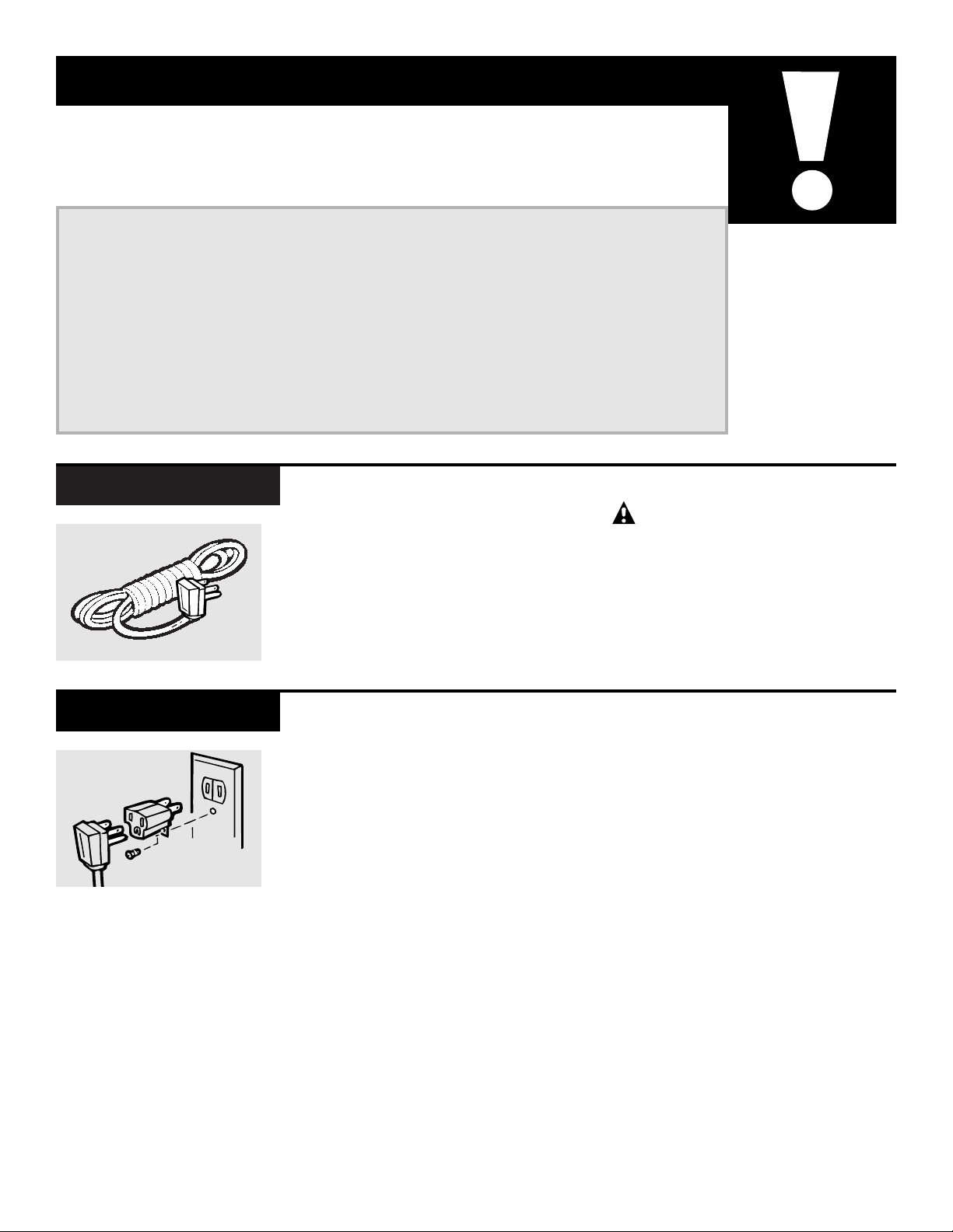
Adapter Plug 115V
This is a temporary method.
UL-listed adapters are available at most hardware stores.
The use of an extension cord is not
recommended. However, if an
extension cord is required to reach
the nearest wall receptacle, use only
a UL-listed, 3-wire, grounded, 14
gauge, 15A, 125V appliance extension cord.
CAUTION:
DO NOT use an extension cord with
any of the 208/230-volt models.
Extension Cord 115V
SAVE THESE INSTRUCTIONS
3
Page 4
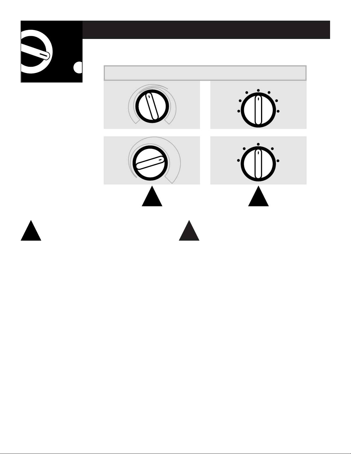
The temp control is used to maintain the
room temperature. The compressor will cycle
on and off to keep the room at the same level
of comfort. When you turn the knob to
COOLER
(blue) the indoor air will become cooler. Turn
the knob to
WARMER
(red) and the indoor air
will become warmer.
HEAT PUMP MODELS
When the outdoor temperature is lower than
25
°F., heat is provided by the electric heater in
the air conditioner instead of by the heat pump.
HIGH COOL
and
LOW COOL
provide cooling with
different fan speeds.
HIGH HEAT
and
LOW HEAT
provide heating with
different fan speeds.
LOW FAN orHIGH FAN
provides air circulation
and filtering without cooling or heating.
NOTE:
If you move the switch from a cool or heat setting
to OFF or to a fan setting, wait at least 3 minutes
before switching back to a cool or heat setting.
A 3-minute delay is automatically provided on the
Heat/Cool and Heat Pump models.
Operating Instructions
The controls on your air conditioner
21
Temp Control Mode Control
1 2
TEMP CONTROLS MODE CONTROLS
Your model will look like one of these.
4
R
E
M
R
A
W
C
O
O
L
E
R
LOW
HEAT
HIGH
HEAT
OFF
LOW
FAN
HIGH
FAN
LOW
COOL
HIGH
COOL
C
O
O
L
E
R
LOW
FAN
HIGH
FAN
OFF
LOW
COOL
HIGH
COOL
Page 5
Cooling/Heating Descriptions
FOR NORMAL COOLING
OR HEATING
Select
HIGH COOL orHIGH
HEAT
with the thermostat
at mid point.
FOR MAXIMUM COOLING
Select
HIGH COOL
with the
thermostat at maximum
cool.
FOR MAXIMUM HEATING
Select
HIGH HEAT
with the
thermostat at maximum
heat.
FOR QUIETER &
NIGHTTIME COOLING
Select
LOW COOLorLOW
HEAT
with the thermostat
at mid point.
3 4 5 6
Each position equals
approximately 3° F.
Limits
heat
temp
Limits
cool
temp
OPEN
CLOSE
On Heat/Cool models, the fan switch lever is
located in a hole through the control panel. To
reach it, you need to remove the front grille.
Use a small screwdriver to change the setting.
Cool only models have a rocker switch on the
front of the control box.
When set at
CYCLE
(down) the fan cycles on and
off when cooling or heating. When set at
CONT
(continuous, up) the fan runs all the time. The
unit is shipped in the
CONT
setting.
The vent control is located behind the front
grille. When set at
CLOSE
, only the air inside
the room will be circulated and conditioned.
You may adjust it by removing the front grille.
When set at
OPEN
, some inside air is exhausted
outside.
NOTE:
The vent lever is taped in the
CLOSE
position when it leaves the factory. Remove
the tape before using.
53
Fan Switch Vent Control
Limiting the maximum and minimum settings
prevents users from turning the control to the
extreme heat or cool positions.
The normal range of the temp control is approx-
imately 60° F to 85° F. The control range may be
narrowed by the use of the temperature limiting
screws located behind the control panel.
Horizontal louvers on the front grille let you
control the air direction up and down.
Remove the front grille to adjust the vertical
louvers side-to-side to direct the air left or right.
64
Temperature Limiting Air Direction
5
Features and appearance may vary.
Page 6

Operating Instructions
Care & Cleaning
Turn the air conditioner off and
remove the plug from the wall outlet before cleaning.
To clean, use water and a mild
detergent. Do not use bleach or
abrasives.
Grille and Case
The coils on the outdoor side of
the air conditioner should be
checked regularly. It is necessary to
remove the air conditioner from
the wall case to inspect them. Dirt
build-up occurs on the surface
which is not visible from the outside. If they are clogged with dirt or
soot it will reduce the cooling or
heating performance and the unit
will not work properly.
They may be professionally steam
cleaned, a service available
through your GE service outlet.
Outdoor Coils
6
The front grille can be removed
for more thorough cleaning or
to make the model and serial
numbers accessible.
To remove:
Pull out from the bottom and lift
up from the tabs on the top of the
case.
To replace:
Hook the tabs on the front grille
even with the tabs on the front of
the case and snap into place.
Front Grille
1
1
2
2
Tab
Grille
Tab
Grille
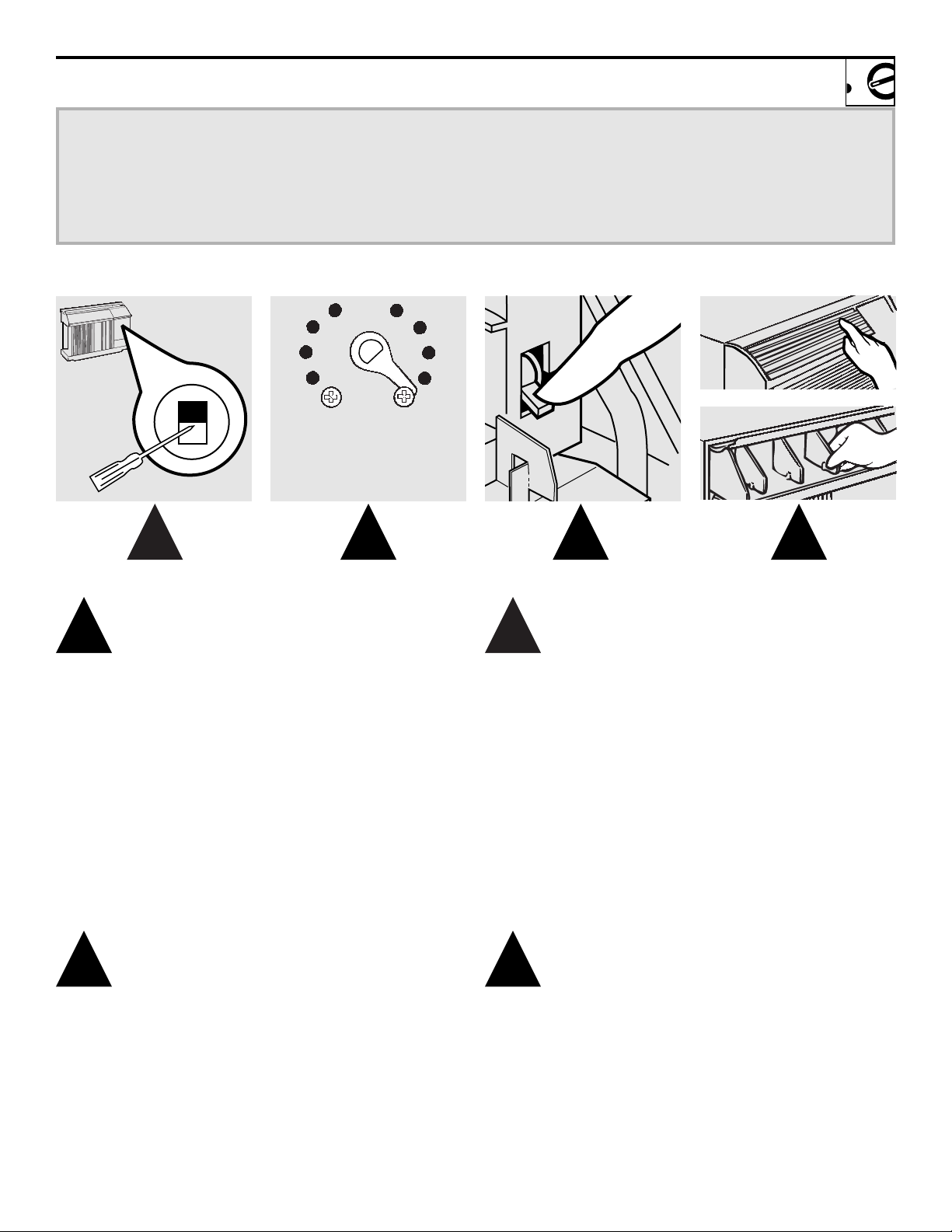
Page 7

Turn the air conditioner off before
cleaning.
The most important thing you can
do to maintain the air conditioner
is to clean the filter at least every 30
days. Clogged filters reduce cooling, heating and airflow.
Keeping the filter clean will:
• Decrease cost of operation.
• Save energy.
• Prevent clogged heat exchanger
coils.
• Reduce the risk of premature
component failure.
To clean the air filter:
• Vacuum off the heavy soil.
• Run water through the filter
from the back side.
• Dry thoroughly before replacing.
On some models,
carefully pull the
tab forward, up and out.
On other models,
pull it down.
Replace the clean filter by pushing
it back into place.
CAUTION:
DO NOT operate the air conditioner
without the filter in place. If a filter
becomes torn or damaged it should
be replaced immediately.
Operating without the filter in
place or with a damaged filter will
allow dirt and dust to reach the indoor coil and reduce the cooling,
heating, airflow and efficiency of
the unit.
Replacement filters are available
from your salesperson, GE dealer,
GE Service and Parts Center
or authorized Customer Care®
servicers.
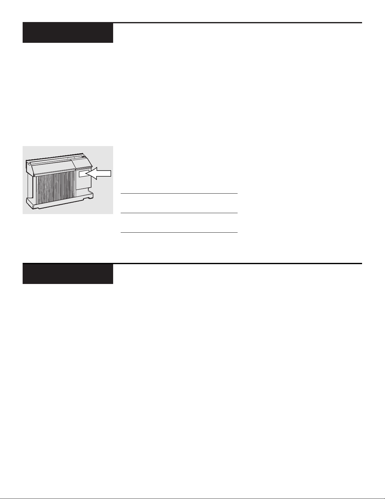
Air Filter
7
Operating Tip:
To maintain optimum
performance, clean
the filter at least
every 30 days.
Dirty filter—Needs cleaning
Clogged filter—Greatly
reduces cooling, heating
and airflow.
FRONT
FRONT
Page 8

• The satisfactory operation of this air condition-
er is dependent upon it being installed in a wall
case, and used with an exterior grille, both
specifically designed for use with this unit.
Use
with an incorrect wall case or with an incorrect
grille may result in poor performance and
could cause damage to the unit. If you are not
sure if you have the correct wall case and the
rear grille please contact the company where
you purchased the unit.
• For personal safety, this air conditioner must be
properly grounded.
• It is important to have the wall outlet and circuit
checked by a qualified electrician if there is any
doubt as to whether a proper ground exists.
• Follow National Electrical Code (NEC) or local
codes and ordinances.
CAUTION:
•
Do not, under any circumstances, cut or remove
the third (ground) prong from the power cord.
•
Do not change the plug on the power cord of this
air conditioner.
•
Aluminum house wiring may present special
problems—consult a qualified electrician.
We recommend that the 230/208-volt, 60 Hz
models be installed on their own single branch
circuit supplying 230/208-volt a.c., protected
with a time delay fuse or circuit breaker.
PPaarraalllleell PPeerrppeennddiiccuullaarr TTaannddeemm
115V. 230/208V. 230/208V.
15 Amp. 20 Amp. 15Amp.
This is recommended for best performance and
to prevent overloading house or apartment
wiring circuits, which could cause a possible fire
hazard from overheating wires.
The 115-volt models require a 115/120-volt a.c.,
60 Hz grounded outlet protected with a 15-amp
time delay fuse or circuit breaker.
The 3-prong grounding plug minimizes the possibility of electric shock hazard.
If the wall outlet
you plan to use is only a 2-prong outlet, it is your
responsibility to have it replaced with a properly
grounded 3-prong wall outlet.
Important Notes
Installation Instructions
Important Electrical Safety–Read Carefully
Installer: Leave these instructions with the appliance.
Owner: Keep these instructions for future use.
Electrical Requirements
8
Page 9

Use GE
For: Description:
Kit Number:
RAK56A100 GE RAB13, 14 & 15 Fits all GE wall cases 26²W ´ 18²H ´ 24²D
(ACLB & RCL Chassis)
RAK107 Hotpoint ACXB10 & 11 Adapts an older Hotpoint wall case to a “J” model chassis.
(ACTB Chassis) Fits Hotpoint wall cases 253¤4²W ´ 167¤8²H ´ 185¤8²D
RAK108 Whirlpool Type 23W Adapts Whirlpool wall case to a “J” model chassis.
Wall Case Fits Whirlpool wall cases 257¤8²W ´ 161¤2²H ´ 231¤8²D
RAK110 GE RAB30 Adapts GE wall case to a “J” model chassis.
(“F” models) Fits the RAB 30 wall case 26²W ´ 18²H ´ 24²D
RAK123 Fedders Wall Case “A” Adapts Fedders wall case to a “J” model chassis.
Fits Fedders wall cases 27²W ´ 163¤4²H ´ 163¤4²D
RAK126 Westinghouse Wall Case Adapts Westinghouse wall case to a “J” model chassis.
(Type 2626D73H01) Fits Westinghouse wall cases 257¤8²W ´ 157¤16²H ´ 16²D
RAB46, 47 & 48 Use these kits for all Standard wall case for “J” model chassis.
other brands not listed. RAG13 stamped aluminum exterior grille included.
Remove the existing case and replace.
RAK690 RAB36, 37, 38, 46, 47 or 48 If you attach a custom architectural outdoor grille,
(J-Chassis) use this kit to ensure proper airflow.
RAG14E RAB36, 37, 38, 46, 47 or 48 Architectural louvered exterior grille
(J-Chassis)
Installing a J-Model in an Existing Wall Case
9
J-model air conditioners may fit in existing wall
cases. However, they often need a kit to properly
adapt the case to the GE air conditioner. Answer
these questions and see the chart below for the
proper kit.
1 What brand air conditioner will you be replacing?
2 What are the dimensions of the wall case
currently in use?
3 What is the model number of the chassis currently
in use? What is the model (or Type) number of the
wall case currently in use?
Frequently, the J-model adapter kit will apply to
another brand model “series” or specific vintage. In these cases, you need the chassis model
number and/or the wall case or “type” number
to confirm the use of the correct adapter kit.
4 What type of outdoor grille is used with the cur-
rent wall case?
There may be an architectural grille attached
to a wall case to enhance the exterior appearance of the building. Custom grilles may be
used with J-model wall cases provided a J-model
adapter kit is also used to ensure proper
airflow.
IMPORTANT!
GE strongly recommends the removal of the
old wall case and the installation of a new
GE Wall Case. If you decide to keep the existing wall case, you may need a kit to ensure
proper performance. If you DO NOT use a kit,
you run the risk of poor performance or
product failure. This is not covered under
the terms of the GE warranty.
J-Model Qualifying Questions
Page 10

Installation Instructions
Install the Air Conditioner in the Case
1
Remove the locking plate on the front left side.
2
Remove the shipping pad inside the air
conditioner next to the compressor.
3
Carefully slide the air conditioner back into
the case. Make sure that the tubing on the unit
does not touch the wall case and that the case
installation is secure.
4
Reinstall the locking plate with the tab behind
the wall case flange. Tighten the screw.
5
Attach the power cord to the base pan with
the clamp.
6
When the wall outlet is to the left, extend the
cord under the unit and hold it in place with
the clamp.
7
Attach the front grille. An opening for the
power cord is on the bottom of the front grille.
REMOVE SHIP PAD!
REMOVE TAPE ON
VENT LEVER!
Power
cord
Clamp
Base
pan
Power cord
Clamp
Locking
plate
Shipping pad
10
Page 11

You may hear a pinging noise caused by water being picked up
and thrown against the condenser on rainy days or when the
humidity is high. This design feature helps remove moisture
and improve efficiency.
You may hear the thermostat click when the compressor cycles
on and off.
Water will collect in the base pan during high humidity or on rainy
days. The water may overflow and drip from the outdoor side
of the unit.
On the heat pump units, water will drip to the outside when the
heat mode is being used. A RAD4 drain kit is available.
The fan may run even when the compressor is not.
11
Helpful Information
Things That Are Normal
Noise Explanation
PIN
G
!
"CLICK"
WHIR!
D R I P
Page 12

12
Air Conditioner
Doesn’t Start
Air Conditioner Does
Not Cool or Heat as
it Should
The air conditioner • Make sure the air conditioner plug is
is unplugged pushed completely into the outlet.
The fuse is blown/circuit • Check the house fuse/circuit breaker
breaker is tripped box and replace fuse or reset the
breaker.
Power failure
• If power failure occurs, turn the mode
control to
OFF
. When power is restored,
wait 3 minutes to restart the air conditioner
to prevent tripping of the compressor
overload.
• There is a protective time delay (up to 3
minutes) in the heat/cool and heat pump
models. Wait 3 minutes for the air
conditioner to resume heating or cooling.
Problem Possible Causes What to Do
Air Conditioner
Freezing Up
Ice blocks the airflow • Set the mode control at
HIGH FAN
or
and stops the air conditioner
HIGH COOL
with the thermostat
from cooling the room at a warmer setting.
Airflow is restricted
• Make sure there are no curtains, blinds
or furniture blocking the front of the
air conditioner.
The thermostat control • Turn the knob to a warmer or cooler setting.
may not be set high The coolest setting provides maximum
or low enough cooling. The warmest setting provides
maximum heating on models with heat.
The air filter is dirty • Clean the filter at least every 30 days.
See the Care and Cleaning section.
The room may have been hot • When the air conditioner is first turned on
or cold you need to allow time for the room to
cool down or warm up.
Cold air is escaping • Check for open furnace floor registers and
cold air returns.
• Set the exhaust vent in the closed position.
Cooling coils have iced up • See freezing up below.
If Something Goes Wrong
Before You Call for Service
Page 13

Notes
13
Page 14

14
Notes
Page 15

800.626.2000
TDD
800-833-4322
GE Service Numbers
We’ll be there!
Open 24 hours a day,
7 days a week.
GE Answer Center
®
800-GE-CARES
(800-432-2737)
We provide expert repair service,
scheduled at a time that’s
convenient for you.
Our factory-trained technicians
know your appliance inside and out—
so most repairs can be handled in
just one visit.
In-Home Repair Service
800-626-2224
With a service contract GE
Consumer Service will still be there
after your warranty expires.
With a multiple-year contract,
you’re assured of future service at
today’s prices.
Service Contracts
800-626-2002
Individuals qualified to service
their
own appliances can have
parts or accessories sent directly
to their home.
VISA, MasterCard and Discover
cards are accepted.
Care and cleaning instructions contained in this manual cover procedures to be performed by any user.
Other servicing generally should be
referred to qualified service personnel. Caution must be exercised,
since improper servicing may cause
unsafe operation.
Parts and Accessories
If for some reason you
are not happy with the
service you receive, here
are three steps to follow
for further help.
First,
contact the people who serviced your appliance. Explain why
you are not pleased.
Next,
if you are still not pleased,
write all the details—including
your phone number—to:
Consumer Relations
GE Appliances
Louisville, KY 40225
Finally,
if your problem is still
not resolved, write:
Major Appliance
Consumer Action Program
20 North Wacker Drive
Chicago, IL 60606
Further Service
15
Page 16

Printed in China
AJCS06 AJCS09 AJES10 AJEH12
AJCH08 AJES09 AJHS10 AJES12
AJCS08 AJCH10 AJCH12
AJHS08 AJCS10 AJCS12
What Is Not
Covered
FULL ONE-YEAR WARRANTY
For one year from date of original purchase, we will provide, free of charge,
parts and service labor in your home to
repair or replace
any
part of the room air
conditioner that fails because of
a manu-
facturing defect.
FULL FIVE-YEAR WARRANTY
For five years from the date of original
purchase, we will provide, free of charge,
parts and service labor in your home to
repair or replace any part of the sealed refrig-
erating system (the compressor, condenser,
evaporator and all connecting tubing)
that fails because of a manufacturing
defect.
This warranty is extended to the original purchaser and any succeeding owner for products purchased for home use
within the USA. In Alaska, the warranty excludes the cost of shipping or service calls to your home.
Some states do not allow the exclusion or limitation of incidental or consequential damages. This warranty gives you
specific legal rights, and you may also have other rights which vary from state to state. To know what your legal
rights are in your state, consult your local or state consumer affairs office or your state’s Attorney General.
Staple sales slip or cancelled check here. Proof of original purchase
date is needed to obtain service under warranty.
For service, call 800-GE-CARES.
AIR
CONDITIONER
WARRANTY
What Is Covered
• Service trips to your home to teach
you how to use the product.
• Improper installation.
If you have an installation problem,
or if the air conditioner is of
improper cooling capacity for the
intended use, contact your dealer
or installer. You
are responsible for
providing adequate
electrical
connecting facilities.
• Replacement of house fuses or reset-
ting
of circuit breakers.
• In commercial locations labor neces-
sary to move the unit to a location
where it is accessible for service by an
individual technician.
• Failure of the product resulting from
modifications to the product or due
to unreasonable use including failure
to provide reasonable and necessary
maintenance.
•
Failure due to corrosion on models not
corrosion-protected.
•
Damage to product caused by improper power supply voltage, accident,
fire,
floods or acts of God.
•
Incidental or consequential damage to
personal property caused by possible
defects with this air conditioner.
Warrantor: General Electric Company. Louisville, KY 40225
 Loading...