

Page 1
GE
Healthcare
|
Aisys
User’s
Software
Reference
Revision
|
7.X
|
Manual
Page 2
E
"A
1)
)
yi
gl
>
Datex-Ohmeda,
User
Responsibility
Inc., a General
CAUTION
Electric
Company,
This
contained
and/or
in
accordance
checked
that
should
become
written
Datex-Ohmeda
parts
instructions
trained
written
have
improper
alteration
U.S.
order
U.S.A.,
doing
business
Product
are
should
the
Federal
will
perform
in
this
User's
inserts,
be
request
personnel.
approval
of a licensed
when
assembled,
with
the
instructions
periodically. A defective
broken,
necessary,
sole
missing,
replaced
provided
use,
by
immediately.
Datex-Ohmeda
for
service
Customer
not
be
repaired
The
of
Datex-Ohmeda.
responsibility
faulty
anyone
law
by
Product
maintenance,
other
restricts
medical
check
local
laws
as
GE
in
conformity
Reference
plainly
advice
Service
Datex-Ohmeda
for
than
manual
operated,
provided.
Product
worn,
Should
recommends
be
Center.
other
than
must
The
any
malfunction
improper
Datex-Ohmeda.
this
device
practitioner.
for
any
Healthcare.
with
the
description
and
accompanying
maintained,
This
should
distorted,
repair
made
in
accordance
and
not
be
user
not
or
or
to
the
This
Product
by
Datex-Ohmeda
altered
of
this
which
repair,
to
sale
Outside
restriction
thereof
labels
and
repaired
Product
contaminated
replacement
that a telephonic
nearest
without
damage,
must
be
used.
or
any
with
written
Product
results
by
or
Parts
of
the
prior
shall
from
or
on
be
the
the
that
may
apply.
or
its
GEO
6
60
6 6
0 6
0
0
0
CO
y
»
Datex-Ohmeda
which
indicates a product
sequential
one
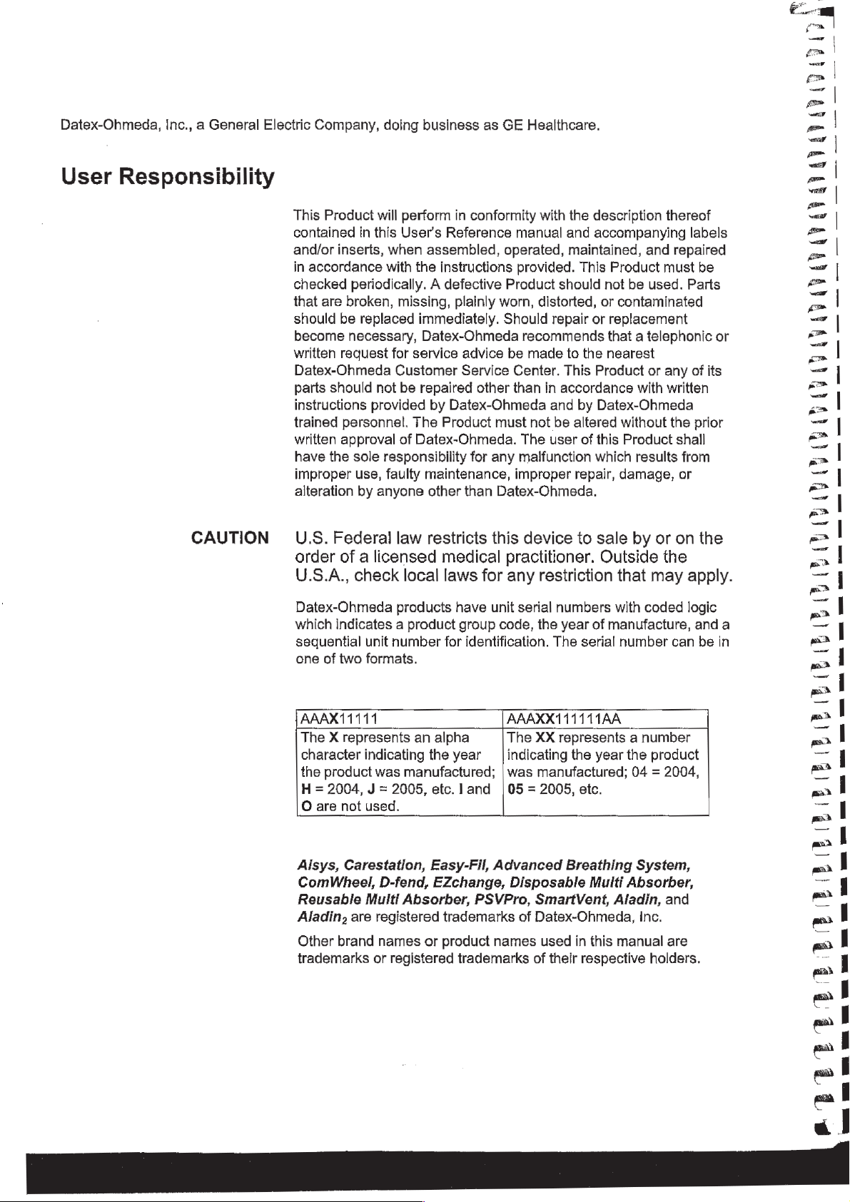
AAAX11111
The X represents
character
the
H = 2004, J =
O are
Aisys,
ComWheel,
Reusable
Aladin,
Other
trademarks
unit
of
two
formats.
indicating
product
was
not
used.
Carestation,
Multi
are
brand
or
D-fend,
registered
names
registered
products
number
manufactured;
2005,
Absorber,
for
an
alpha
the
etc. l and
Easy-Fil,
EZchange,
trademarks
or
product
have
group
identification.
year
trademarks
unit
serial
numbers
code,
the
year
The
AAAXX111111AA
The
XX
represents a number
indicating
was
05 = 2005,
the
manufactured;
with
of
manufacture,
serial
number
year
the
etc.
coded
product
04 = 2004,
Advanced
Disposable
PSVPro,
of
names
Breathing
Multi
SmartVent,
Datex-Ohmeda,
used
in
this
of
their
respective
System,
Absorber,
Aladin,
Inc.
manual
holders.
and
are
logic
can
anda
be
in
ΑΛΛΑ
ΟΛ
ο
Page 3
1
Introduction
Table
of
Contents
2
System
Controls
and
Intended
Symbols
Typeface
Abbreviations
Menus
System
Advanced
Optional
Non-circle
ACGO
Scavenging
Scavenging
Scavenging a gas
Aladin
Display
use
.......,...,..,.............,.......
used
in
the
manual
conventions
used
or
on
the
equipment........
........,,,,.,,,.,,,...,.
.........
overview
breathing
(optional)
cassette
controls
.................................
system
ABScomponenits.......................
circuit
the
from
....,......,..,.................
ACGO
an
controls
.................,...............
(ABS)
..............................
sample
auxiliary
monitor
........................
components
flow
manual
sample
................
flow
.........
breathing
............
circuit
ーー
2-10
2-10
2-11
1-2
1-4
1-7
1-7
2-2
2-5
2-7
2-8
2-9
2-9
2-12
3
Operation
M1179475
Anesthesia
Waveform
Digit
field
Usingmenus
Turning
Start
¡IN
on
case
Using
Using
Minimum
default
customized
system
the
(start
display
fields
............................,......
...................
Alveolar
..............................
system
gas
flow)
settings
.........................
0.0
..,....................,,,...
........,,.,,,,............
...........................
settings
Concentration
.................,......
(MAC)
............
2-13
2-15
2-15
2-16
3-2
3-3
3-4
3-4
3-5
3-6
Page 4
Aisys
n
Ventilator
Using
Using
setup
quick
Vent
Changing
Gas
setup
Using
Using
quick
Gas
Changing
Changing
Spirometry
Setting
loop
Scaling
Spirometry
Setting
setup
patient
Selecting a data
Setting
spirometry
.........,..................,..,..
keys
Setup
ventilator
....,.................,.....,.
menu
..........,.....,...,..,.
modes
and
settings
............
..........,,...................,...,..
keys
Setup
gas
circuit
し
.......,..........,....,.,,...
menu
and
type
に
に に に に
type
.......................,.....
.....................,..,
settings
.............,,......,.
..................,..,.....
に に
レト
し に
トト し し に レト
トス
トレ
トレー
ュー
トバ
.........,....,...,,....,.,....,.....
................................
and
sensor
source
split
type
..................
........................
screen
......,............
3-7
3-7
3-8
3-8
3-9
3-9
3-9
3-9
3-10
3-11
3-12
3-13
3-14
3-14
3-15
3-15
Main
Menu
Trends
Cardiac
Fresh
Screen
Select
Screen
Alarm
Setting
Volume
MWTValarms
CO2
Auto
.....,.................,.............
......,...........,.....,............,
bypass
gas
usage
configuration
pad6 1 し
setup
setup
............................,.......
alarm
apnea
..............................
.........,.............,......
..........,..................
レレ
ュー に し に
ーー に に に
ーー に ーー
トト
................................
limits
........,...................
...............................
..........................
alarms
MV
................................,
limit
................,....,,......,.0
トト
ーー トー
トーーー
AltenateOZ2control..............................
EZchange
Condenser
canister
(optional)
(optional)
..,.....,..............
........................,....
ων
3-16
3-17
3-18
3-19
3-20
3-20
3-21
3-23
3-23
3-24
3-24
3-24
3-25
3-26
3-27
3-28
Passive
AGSS
(optional)
...............,.......,..
3-29
M1179475
Page 5
AAA
4
Preoperative
5
Preoperative
Checkout
Tests
Active
Every
Before
Inspect
Aladin
Flow
Circuit
Checkout
Leak < 250
AGSS
Connecting
Connecting
day
every
before
the
system
(optional)
active
active
patient
cassette
and
pressure
compliance
menu
mil
No
................
...........................
AGSS
adjustable
your
first
with a flow
AGSS
patient
...........,..,.....
indicator
..............
.....,.,.,,.................,....
...............,................
installation
calibration
compensation
.........................
.......................
....................
.........,.,,.............,.,,.,,.
...........,.,,,............,,,,,..
Yes............................,......,.....
.......
이
3-30
3-31
3-31
4-2
4-3
5-2
5-3
5-4
5-4
5-5
5-5
아다
5-5
5-5
Machine
Individual
check
Machine
Machine
Machine
circuit
Machine
System
...................,...............
check - system
check - circuit
check
O2
-
...............
...............,,........
check - monitor
checks
.................................
rr
Circuit................
........................
6.el
........................
0.
iie
CircutOZcel.................................
LowPleak
Low P leak
Agent
Positive
low
..
(machines
delivery
pressure
with
ACGO)
.......,........
...............................
leak
test
(ACGO
systems
5-6
5-6
5-7
5-7
5-7
5-8
νεος
5-8
5-8
5-9
ennen
nne
5-9
5-9
5-10
only)....5-11
M1179475
1
Page 6
Aisys
Г
wi
らし
し
6
Airway
7
Alarms
Modules
and
Troubleshooting
Airway
Parameters
Automatic
Calibration
Alarms
modules
Connection
Data
source
CO2
setup
O2
setup
Agentsetup
Spirometry
agent
Alarm
Silencing
priorities
........,.........................
to a patient
setup
......................................
alarms
................,......,.,......
...............,......,.....,,....
......................,,,,,........
..........,...,,,,,...............,.
..........................
setup
...........................,,.
identification
............,,,,.........,......
..............,.,...............
.........................
.......................
0...
k
6-2
6-4
6-5
6-5
6-5
6-5
6-5
6-5
6-6
6-6
7-2
7-2
7-2
らし
しい
|
è
0666666460
8
Setup
and
Connections
Display
during
De-escalatinggalarms...........................
Battery
internalfailure................................
List
of
Alarm
Alarm
Breathingsystemproblems
Electrical
Pneumatic
Setup
Canister
When
Removingacanister
Removingan
changes
alarms
indicator
alarms
ranges
tests
..................,,,................
problems
problems
warnings
setup
to
..............,....,........,.....
...............................
..........,..,...,...,.....,........
...............,,...,.........,....
........................
......,................,.......
.............................
.............,..,.........,........
................,,..,..............
changetheabsorbent
...........................
EZchangecanister..................
...................
7-2
7-3
7-3
7-3
7-4
7-13
7-15
7-17
7-18
7-19
8-2
8-4
8-5
8-6
8-6
n000000000000000000000
iv
Reusable
Multi
Absorber
canister
filling
.............
8-7
M1179475
van
!
|
vo
Page 7
Table
of
Contents
Electrical
Pneumatic
connections
Mains
Ouilets
Patient
Serial
inlet
..............,.........,..,..........
monitoring
port....,.,.....................,.,,.,..
connections
Pipeline
inlets
Scavenging
Sample
gas
............,..,...................
...........,........,............
return
Pneumaticpoweroutlet
Vacuum
Venturi
Auxiliary
How
to
Pin
DIN
suction
suction
02
install
gas
indexed
cylinder
flowmeter
cylinder
connections
...............,...,.........
battery
backup
.................
...............,..,...,....
........................,.......
port
....................,...
........................
regulator
regulator
cylinders
(optional)
(optional)
(optional)
..............
...............
.................
...................,....
yokes
.........,..,.....,..
.......................
8-9
8-9
8-9
8-9
8-10
8-11
8-11
8-11
8-12
8-12
8-13
8-13
8-14
8-15
8-15
8-15
9
User
Maintenance
High-pressureleaktest
How
to
attach
Repairpoliey
Maintenance
equipment
....................................
summary
Datex-Ohmeda
Circuit
OZcelireplacement
Calibratitonmenu
Flow
and
pressure
Circuit
Airway
Backlight
How
21%
100%
to
Oz
cell
O,
calibration
O;
calibration
gas
calibration
test
help
prevent
calibration
................,...................
........................
to
the
top
of
the
machine......
and
schedule
approvedservice
.........................
..,...,.,........
.................
.................................
calibration
.......................
«ον
εν
νεο
εκ
ρε νε ων
.............................
.......................,....
.............................
water
buildup
....................
8-16
8-17
9-2
9-2
9-3
9-4
9-5
9-5
9-6
9-6
9-6
9-6
9-7
9-7
M1179475
Page 8
Aisys
10
Parts
Flow
sensor
module
.............,..,..,...,......
10-2
11
Specifications
and
Theory
Breathing
Bellows
Complete
Absorber
Exhalation
AGSS..............
EZchangecanistersysteem.........................
Condenser
Test
of
System
Gas
O2flow..................................1.
AlrandN20.................................
Mixed
circuitmodule
.................,..,..................
Advanced
canister
tools
valve
.....,..,...,..,......,..,..........
and
...........................,....
assembly
system
..........................
Breathing
1...
parts
System
.........................
........,.............,
...............
Operation
pneumatic
supplies
gas
circuits
.......,.........,.......
......,............,,..,........
...................................
10-3
10-4
10-5
10-6
10-7
10-8
10-9
10-10
10-11
11-2
11-4
11-4
11-4
11-4
'
'
'
'
|
EZchange
Condenser
Pneumatic
Gas
ACGO
Non-circle
Pneumatic
Electrical
Electricalpower
Power
Battery
Flow
specifications
Breathing
Gas
Physical
Environmental
canister
...................,..............
specifications
supplies
Port
relief
circuit
power
block
diagram
cord
...............,..,..,...,...,.,..
information
system
scavenging
specifications
requirements
...................,...,....
..........................
................................
........................,....
relief
.................................
................,.............
specifications....................
.........................
outlet
........,...............
...........................
.........,.................
.............................
...........................
......................
11-10
11-10
11-11
11-12
11-13
11-13
11-5
11-5
11-5
11-5
11-5
11-5
11-6
11-7
11-9
11-9
|
.
,
.
e
r
r
r
n
r
n
n
~
-
i
-
vi
M1179475
と
è
a
á
Page 9
Airway
Gas
module
specifications......................
specifications
...........................
11-14
11-14
Typical
Suction
Ventilator
O2
performance
regulators
theory
monitoring
Ventilation
Ventilation
Ventilation
Ventilator
operating
Pneumaflcg
Fresh
Pressure
Volume
gas
..,.....,...,................,....,
.............,......,,...,,....,,...
Oxygeh
Ventilator
Electronically
Aladin,
accuracy
controlled
cassettes
.........................
(optional)
......................
..........,,....,....,.,,....,..
theory
modes
modes
mode
compensation
に
に に に に に に に に レ に
of
operation
...............
......,.....,,,............
factory
transition
specifications
し し
にし に に に に に
default
settings
.....,..........,.,..
..................
に に に に に ーー に トト
ーー
................,,....
トト
トー
トー
トト
トト
トー
レト
data
...,.....,...............
vaporizer
.............,....,,.....,..
and
Aladin
.........
レレ
トト
cassette
トト
ーーー
ーーーー・
トト
. .
11-15
11-16
11-17
11-18
11-18
11-26
11-26
11-27
11-27
11-27
11-27
11-27
11-27
11-28
11-29
11-30
Aladin
Electromagnetic
Guidance
cassettes
compatibility
and
manufacturer's
.............................
(EMC)
................
declaration
-
electromagneticemissions.....................
Guidance
electromagnetic
Recommended
Electricalsafey
IEC
60601-1Classification........................
Standards
System
Integral
Not
and
manufacturer's
immunity
separation
declaration
.....................
distances
........,....
................................
......................,.............
components
...........,........................
integral
..................,.....,,...,.,.
............................
-
11-31
11-32
11-32
11-33
11-35
11-36
11-37
11-37
11-38
11-38
11-38
vii
Page 10
x
ai
Aisys
12
Super
13
Vaporizer
User
Mode
cassettes
Install/Service
Using super
Menus
...............,......,.....,,....,,....
Cumulative
Volumeapneasetup
Setting
Trends
Setting
Parameter
Page
Configuring
time
setup
colors
Setup
menu
user
gas
and
settings
case
.............,.,...,...,.....
mode
usage
date
...................,.........,,..
and
................,.........,.....
defaults
..................,......
..............,....,.....
..........................
..........................
units
........................
...........,.....,..........
.....................
12-2
12-3
12-4
12-4
12-5
12-6
12-7
12-9
12-10
12-10
12-12
LU 47
7
Er
On
EU
CU ON ED
AB ED CU ED
CB
CU
D
Index
Warranty
Vaporizer
Aladin,
Aladin
Installing
Cleaning
Draining
Draining
Filling
FillingwithEasy-Filsystem.....................
Filling
Filling
Filling
Filling
Filling
Filling
..............,....,,.....,....,,...,.
cassette
cassette
cassettes
.....................,..,..,...,,,....
cassettes
halothane
Aladin,
Aladin
cassettes
with
with
cassettes
with
with
with
variants
variants
..............................
....................,..........
cassettes
Quik-Fil
Saf-T-Fil
keyed
Ouik-Fil
Saf-T-Fil
filler
.....,...........,.....
.......................
......................
...........................
system
bottle . ....................
.........................,
system
bottle
.....................
system
..................
...................
.....................
13-2
13-2
13-4
13-6
13-6
13-6
13-7
13-7
13-8
13-9
13-10
13-12
13-12
13-14
13-15
CB
CB
CB
D
CB
CB
CB
CB
CB
OÙ
OU
CB CB
CB
UD
1
viii
M1179475
г
100,
Page 11
1
Introduction
|
|
ii
ji
|
|
|
1
Ì
In
WARNING
this
section
Read
understand
*
ㆍ
*
»
Before
*
・
If a test
Datex-Ohmeda
equipment.
each
All
system
All
warnings
How
How
using
Complete
section.
Test
Intended
components
the
to
use
to
test
all
other
fails,
ue
User's
following
connections.
and
each
each
the
system:
all
of
the
system
do
not
trained
し に に に に に に に に に に に に に に
before
cautions.
system
system
tests
use
component.
component.
in
components.
the
equipment.
service
the
representative
Reference
using
“Preoperative
に に に に に トト に に
this
Have
トッ
manual
system:
レート
and
Tests”
a
repair
ーー し ーー
the
1-2
1179475
Symbols
Typeface
Abbreviations
used
conventions
in
the
manual
used
............,..,......,,.......,..,.
or
on
the
equipment
.........,..,....,........
........
1-4
1-7
1-7
1-1
Page 12
ee
ВЯ
ας
Aisys
Intended
use
Aisys
means
The
Aisys
integrated,
respiratory
bays
allow
patient
monitors.
of
non-Datex-Ohmeda
connections
display
offering
and
ventilation
This
anesthesia
inhalation
small
breathing
response
as
achieving
circuit
This
anesthesia
offering
and
electronic
features
Ventilation
Anesthesia
Carestation
featuring
monitoring,
for
monitors
Optionally,
to
arm
helps
control
anesthetics,
time
90%
with a 2
Volume
optional
with
spontaneously
Mandatory
Volume
Control
volume
5
ml
ventilation
This
This
and
system’s
circuit
Ventilation
Guarantee
Ventilation, a patient
of
20
ml.
can
be
measured.
of a broad
anesthesia
integrated
is
fully
autoclavable.
elegance
volume,
is
scalable,
the
most
and
the
physical
and
supports
the
open
patient
the
hospital
keep
the
of
all
hemodynamic,
parameters.
system
is
Air,
system
of
l/min
system
Control
PEEP.
an
volume
less
than 7 seconds.
of
the
setting
fresh
uses
Ventilation
The
Pressure
Apnea
breathing
(SIMV)
(PCV-VG),
In
Pressure
These
patient
system
uses
breathing
while
and
increasing
Integrated
System.
flexible,
advanced
breathing
integration
mounting
architecture
monitors,
information
anesthetist’s
gas
designed
O2,
and
for
N20.
allows
change
gas
flow.)
SmartVent
with
proven
Control
Backup
patients,
SmartVent
Ventilation,
(PSVPro)
Synchronized
modes,
and
VCV
can
be
ventilated
Control
advanced
range.
the
Advanced
system
Its
minimizing
is
fully
integrated
the
easy
tube
work
and
functionally
design,
system.
of
legacy
of
record
system.
focus
delivery,
ventilation,
In
addition,
Datex-Ohmeda
other
GE
design
supports
keeping,
The
on
the
anesthetic
mixing and
The
anesthesia
an
anesthetic
(Agent
response
measured
ventilation
tidal
volume
technology
Pressure
that
is
Intermittent
Pressure
cardiac
Contro!
bypass.
using a minimal
Ventilation,
volumes
features
Breathing
to
remove
design
connections,
surface
area.
module
Healthcare
mounting
and
INview
movable
patient
agent,
delivering
system's
agent
delivery
time
while
in
non-circle
technology
compensation
also
Support
used
for
Ventilation-
In
Volume
as
allow
for
the
System
and
disassemble
enhances
minimizing
by
defined
tidal
low
as
(ABS).
the
i
kani
MM
σας
SAM
SE
SR
E
ας
RR
RR
ee
co
—r>._
==
—
—
——
i
:
i
WARNING
This
anesthesia
is
easy
to
add
investing
This
This
well
to
the
Explosion
in a new
anesthesia
system
trained
in
instructions
Hazard.
anesthetic
system
new
technologies
system.
system
must
only
the
use
in
this
agents.
is
designed
is
not
be
operated
of
this
User's
Do
not
for
and
ventilation
suitable
by
product.
Reference
use
this
expansion
capabilities
for
use
in
an
authorized
It
must
be
manual.
system
and
upgrades,
MRI
environment.
medical
operated
with
flammable
so
without
personnel
according
M1179475
it
ORGGG
"m
Page 13
1
Introduction
に
0
000000
o o
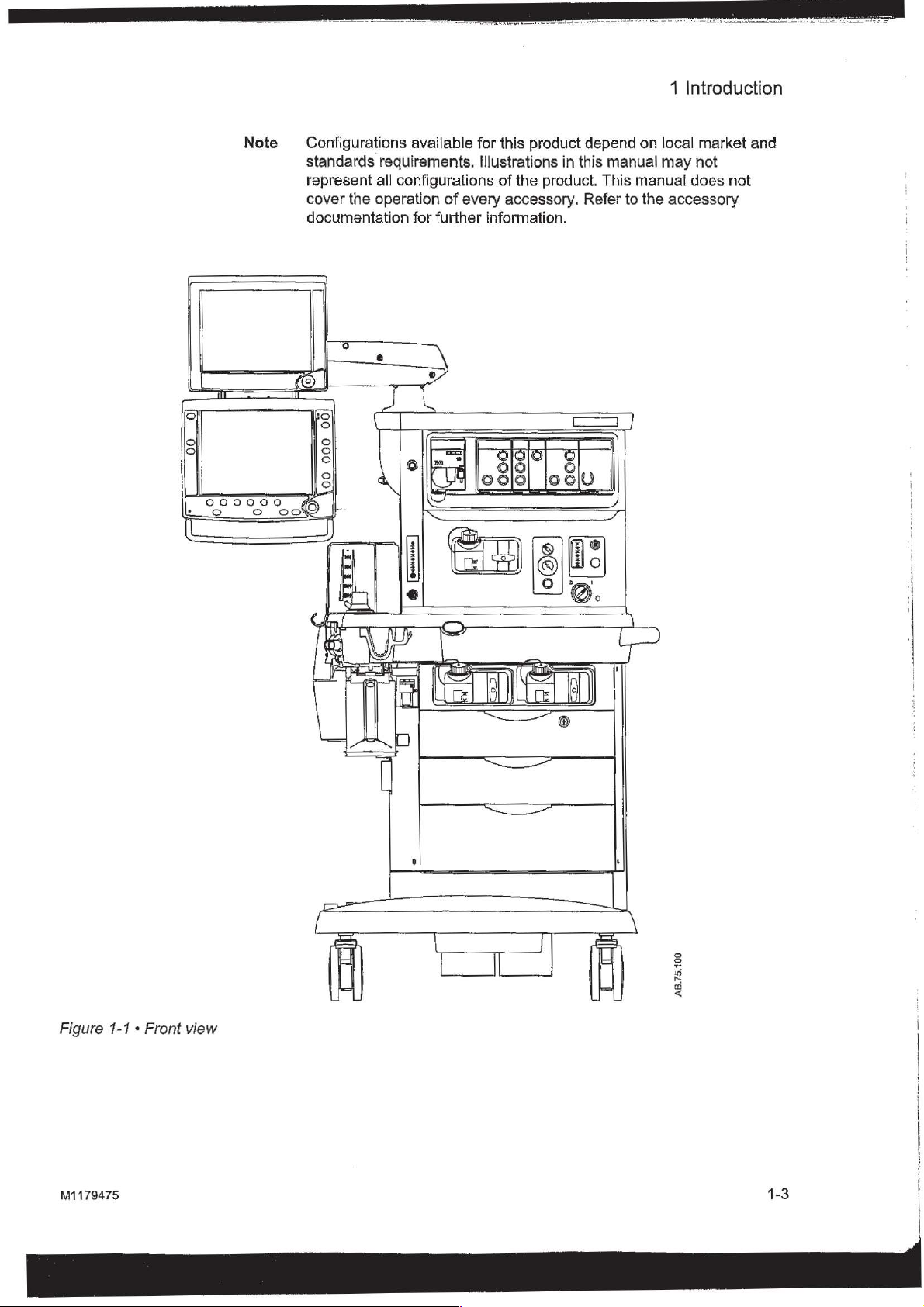
Note
Configurations
standards
represent
cover
the
documentation
00
|
000
00
O
oo
available
requirements.
all
configurations
operation
for
further
>
of
every
_)
for
this
product
Illustrations
of
the
accessory.
information.
in
product.
depend
this
manual
This
Refer
on
manual
to
the
local
market
may
not
does
accessory
and
not
Figure
1-1 « Front
view
LADA
口
SE)
AB.75.100
M1179475
1-3
Page 14
る
Aisys
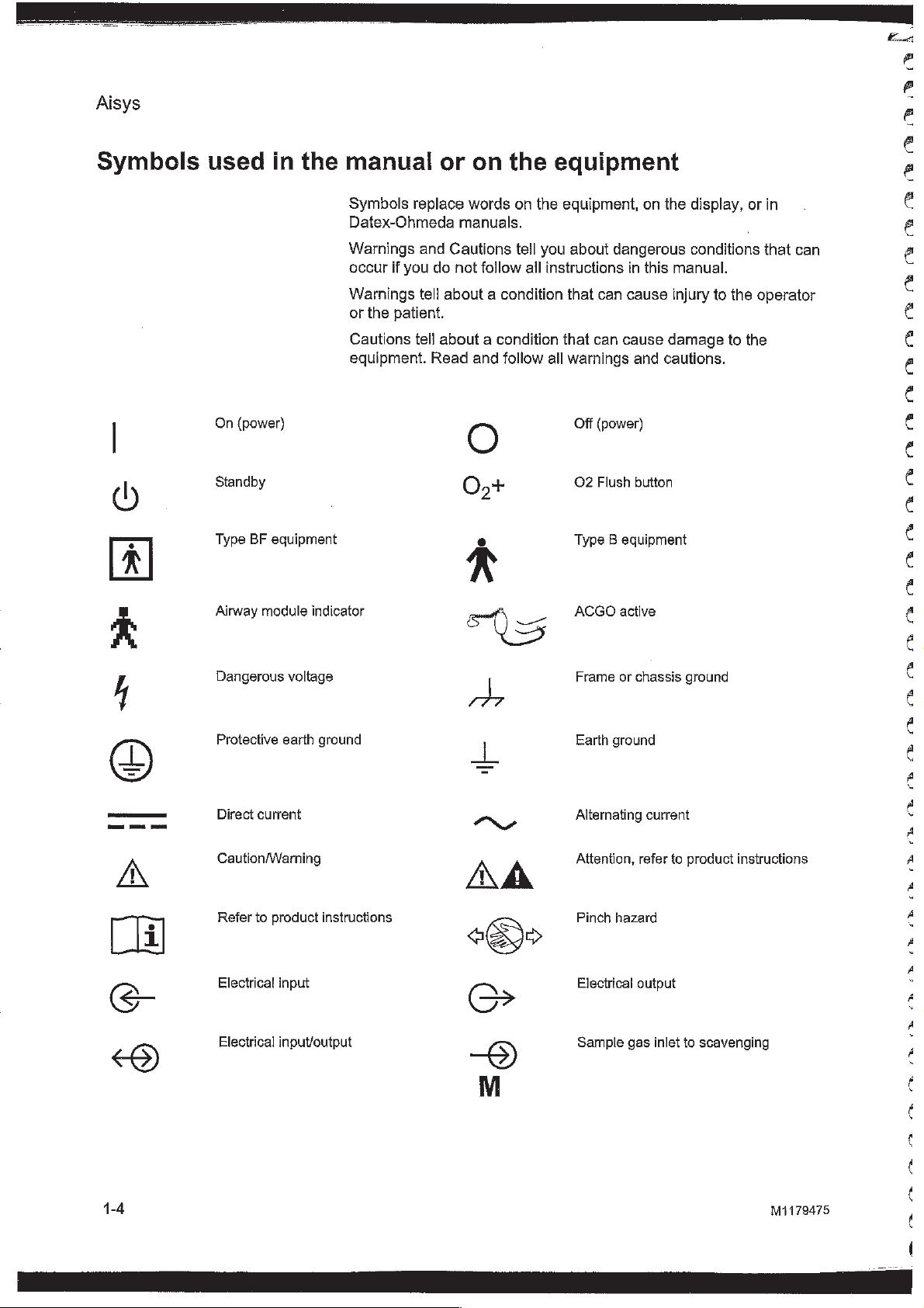
Symbols
used
On
(power)
Standby
Type
BF
Airway
in
the
equipment
module
manual
Symbols
Datex-Ohmeda
Warnings
occur
Warnings
or
the
Cautions
equipment.
indicator
or
replace
and
if
you
do
tell
about a condition
patient.
tell
about a condition
Read
on
words
manuals.
Cautions
not
follow
and
follow
то
the
equipment
on
the
equipment,
tell
you
all
instructions
that
all
on
the
about
dangerous
in
this
that
can
cause
can
cause
warnings
Off
O2
Type B equipment
ACGO
and
(power)
Flush
button
active
cautions.
display,
conditions
manual.
injury
to
damage
the
to
or
the
in
that
can
operator
を
を
e
る
e
€
é
€
€
€
6
é
€
€
č
€
€
6
é
€
pe
Dangerous
Protective
p
|
Direct
Caution/Warning
>
Refer
by)
Electrical input
9
Electrical
S
voltage
earth
current
to
product
input/output
ground
instructions
Frame
Earth
та»
P
A
Alternating
Attention,
Pinch
à
Electrical
9
Sample
26
or
chassis
ground
current
refer
hazard
output
gas
to
inlet
to
ground
product
scavenging
instructions
É
É
€
€
É
é
É
i
<
é
A
,
4
Ê
é
M1179475
(
(
¢
(
(
Page 15
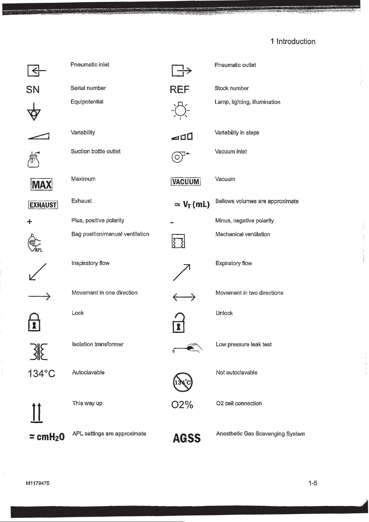
1
Introduction
he?
EXHAUST
"gg
Pneumatic
Serial
Equipotential
Variability
Suction
Maximum
Exhaust
Plus,
Bag
inlet
number
bottle
outlet
positive
position/manual
polarity
ventilation
VACUUM
=
Vr
(mL)
Pneumatic
Stock
Lamp,
Variability
Vacuum
Vacuum
Bellows
Minus,
Mechanical
outlet
number
lighting,
in
inlet
volumes
negative
illumination
steps
are
approximate
polarity
ventilation
+
A
TN
=
業
134°C
n
Inspiratory
Movement
Lock
Isolation
Autoclavable
This
flow
in
transformer
way
up
one
direction
02%
Expiratory
Movement
Unlock
Low
pressure
Not
autoclavable
O2
cell
connection
flow
in
two
directions
leak
test
M1179475
AO
ZZ
=
cmH20
APL
settings
9s
are
are
approximate
app
AGSS
Anesthetic
Gas
Scavenging
System
Page 16
Aisys
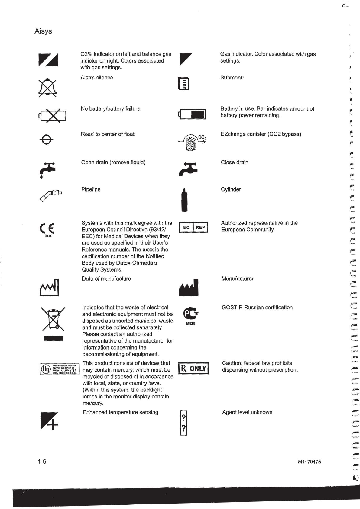
02%
indicator
indictor
with
Alarm
No
Read
Open
on
right.
gas
settings.
silence
battery/battery
to
center
drain
on
left
Colors
failure
of
float
(remove
and
balance
associated
liquid)
gas
Gas
indicator.
settings.
Submenu
Battery
battery
EZchange
Close
in
power
drain
Color
use.
Bar
remaining.
canister
associated
indicates
(CO2
amount
bypass)
with
gas
全
TT
of
RAR
Sw
г
ms
LAMP
CONTARE
MERCURY,
DISPOSE
ACCORDING
IEE.
TO
LAM,
te
ATATELODAL
жа,
Pipeline
Systems
European
EEC)
are
Reference
certification
Body
Quality
Date
Indicates
and
disposed
and
Please
representative
information
decommissioning
This
may
recycled
with
(Within
lamps
mercury.
Enhanced
with
Council
for
Medical
used
as
specified
manuals.
number
used
by
Systems.
of
manufacture
that
electronic
as
unsorted
must
be
collected
contact
concerning
product
contain
local,
consists
mercury,
or
disposed
state,
this
system,
in
the
monitor
temperature
this
Datex-Ohmeda’s
the
equipment
of
mark
agree
Directive
Devices
in
their
The
xxxx
of
the
waste
of
municipal
separately.
an
authorized
the
manufacturer
the
of
eguipment.
of
devices
which
of
in
or
country
the
backlight
display
sensing
with
the
(93/42/
when
they
User’s
is
the
Notified
electrical
must
not
be
waste
for
that
must
be
accordance
laws.
contain
Cylinder
ЕС | ВЕР
Authorized
European
Manufacturer
peel
GOST R Russian
©
ME20
RK
ONLY
Caution:
dispensing
Agent
representative
Community
federal
level
law
without
unknown
in
the
certification
prohibits
prescription.
OR OR
OO GO
OO
OO
OO
OU
OO
|
EC
i
Pi
пой
M1179475
Page 17
Agent
level
indicates
sensing
amount
supported.
of
agent
Bar
remaining. 四 ®
點
When
moving
anesthesia
arm
in
the
or
transporting
machine,
transport
1
Introduction
place
the
position
as
display
shown.
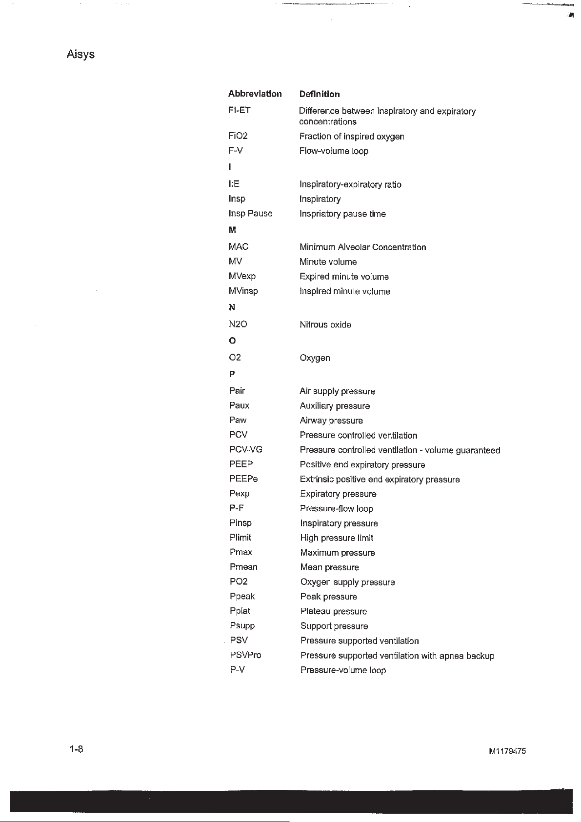
Typeface
conventions
Abbreviations
used
Names
typeface;
Menu
Setup.
Messages
quotes;
When
are
example,
Abbreviation
A
AA
ABS
AGSS
written
ACGO
Alt
02
APL
APN
of
hard
for
items
for
referring
“System
keys
example,
are
written
that
are
example,
to
different
in
italic
Definition
Anesthetic
Advanced
Auxiliary
Anesthesia
Alternate
Adjustable
Apnea
on
the
Normal
in
bold
displayed
‘Check
sections
typeface
Controls
agent
breathing
Common
02
pressure-limiting
display
Screen.
italic
on
the
sample
and
enclosed
and
Menus.”
Gas
Gas
Scavenging
and
modules
typeface;
screen
gas
and
are
out.’
other
in
system
Outlet
System
are
for
example,
enclosed
documents,
double
quotes;
written
Vent
in
single
the
for
in
names
bold
1179475
CGO
CO2
Compl
ET
EtCO2
EtO2
Exp
FICO2
Common
Carbon
Compliance
End-tidal
End-tidal
End-tidal
Expiratory
Fraction
Fraction
Gas
dioxide
concentration
carbon
oxygen
of
of
Outlet
dioxide
inspired
inspired
gas
carbon
dioxide
Page 18
Aisys
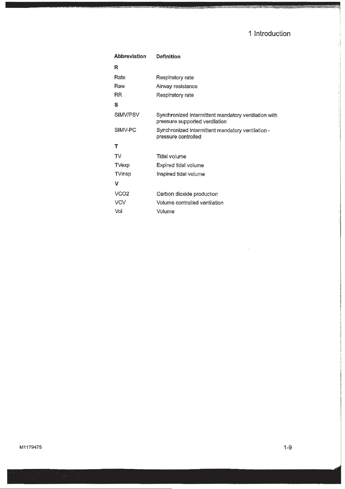
Abbreviation
FI-ET
FiO2
F-V
I
LE
Insp
Pause
Insp
M
MAC
MV
MVexp
MVinsp
N
N20
o
02
P
Definition
Difference
between
inspiratory
concentrations
Fraction
Flow-volume
Inspiratory-expiratory
of
inspired
loop
oxygen
ratio
Inspiratory
Inspriatory
Minimum
Minute
Expired
Inspired
Nitrous
pause
Alveolar
volume
minute
minute
oxide
time
Concentration
volume
volume
Oxygen
and
expiratory
Pair
Paux
Paw
PCV
PCV-VG
PEEP
PEEPe
Pexp
P-F
Pinsp
Plimit
Pmax
Pmean
PO2
Ppeak
Pplat
Psupp
PSV
PSVPro
PV
Air
supply
pressure
Auxiliary
Airway
Pressure
Pressure
Positive
Extrinsic
Expiratory
Pressure-flow
Inspiratory
High
Maximum
Mean
Oxygen
Peak
Plateau
Support
Pressure
Pressure
pressure
pressure
controlled
controlled
end
expiratory
positive
pressure
pressure
pressure
pressure
pressure
supply
pressure
pressure
pressure
supported
supported
loop
limit
Pressure-volume
ventilation
ventilation - volume
pressure
end
expiratory
pressure
ventilation
ventilation
loop
pressure
with
apnea
guaranteed
backup
1-8
M1179475
Page 19
1
Introduction
Abbreviation
R
Rate
Raw
RR
s
SIMV/PSV
SIMV-PC
T
TV
TVexp
TVinsp
VCO2
VCV
Vol
Definition
Respiratory
Airway
resistance
Respiratory
Synchronized
pressure
Synchronized
pressure
Tidal
Expired
Inspired
Carbon
Volume
Volume
supported
controlled
volume
tidal
tidal
dioxide
controlled
rate
rate
intermittent
ventilation
intermittent
volume
volume
production
ventilation
mandatory
mandatory
ventilation
ventilation
with
-
M1179475
Page 20
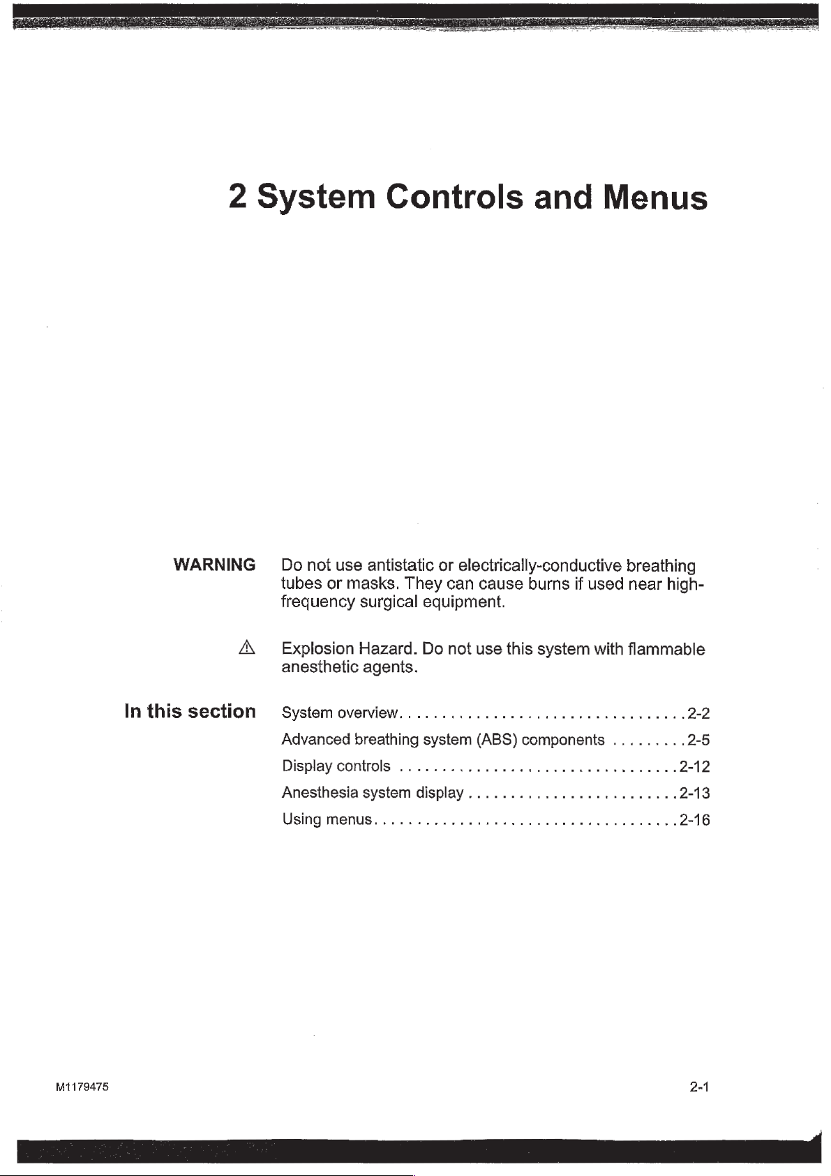
2
System
Controls
and
Menus
In
WARNING
this
A, — Explosion
section
Do
not
use
antistatic
tubes
frequency
anesthetic
Systemovemview.............................
Advanced
Display
Anesthesia
Using
or
masks.
surgical
Hazard.
agenis.
breathing
controls
system
menus........,....,............,......,..
or
electrically-conductive breathing
They
can
cause
equipment.
Do
not
use
system
.................................
display
(ABS)
................,........
burns
this
system
components
if
used
with
near
flammable
.........
high-
2-2
2-5
2-12
2-13
2-16
M1179475
EE
2-1
RÉ
Page 21
Aisys
\
À
~
System
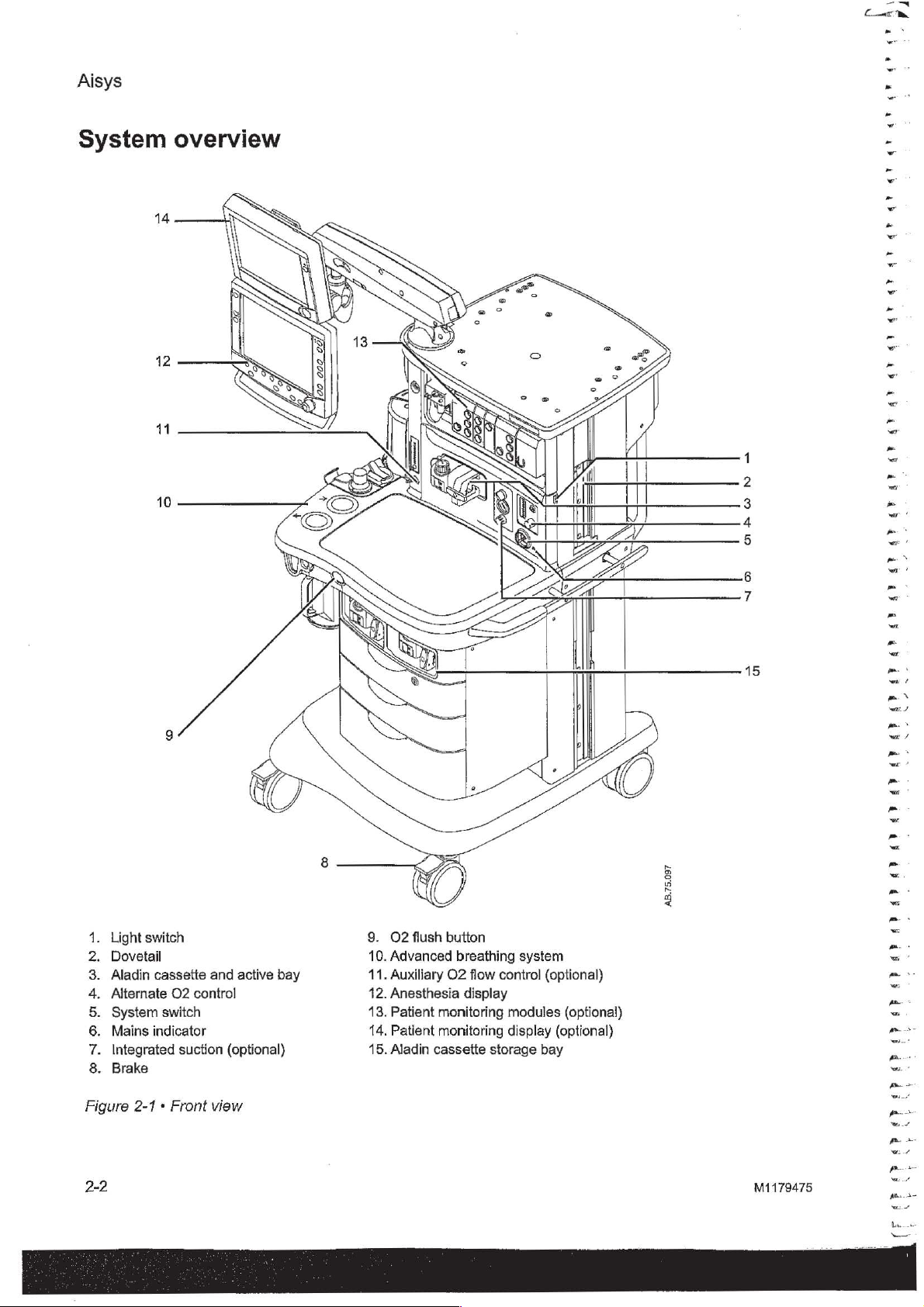
overview
OOOO
1
2
3
4
5
6
OOM
e
,
,
MOOD
1.
Light
2.
Dovetail
3.
Aladin
4.
Alternate
5.
System
6.
Mains
7.
Integrated
8.
Brake
Figure
switch
cassette
02
control
switch
indicator
suction
2-1 * Front
and
active
(optional)
view
bay
9.
02
10.
Advanced
11.
Auxiliary
12.
Anesthesia
13.
Patient
14,
Patient
15.
Aladin
flush
button
O2
monitoring
monitoring
cassette
breathing
display
flow
storage
system
control
modules
display
bay
(optional)
(optional)
(optional)
s
7
15
;
OOOO
=
me
м
/
~
-
-
^
-
^
A.
m
м
a
me
a
=
m
m
i
oc
_
.
2-2
M1179475
pera
ps
©
Page 22
Item,
4
5
6
7
Figure
2-1
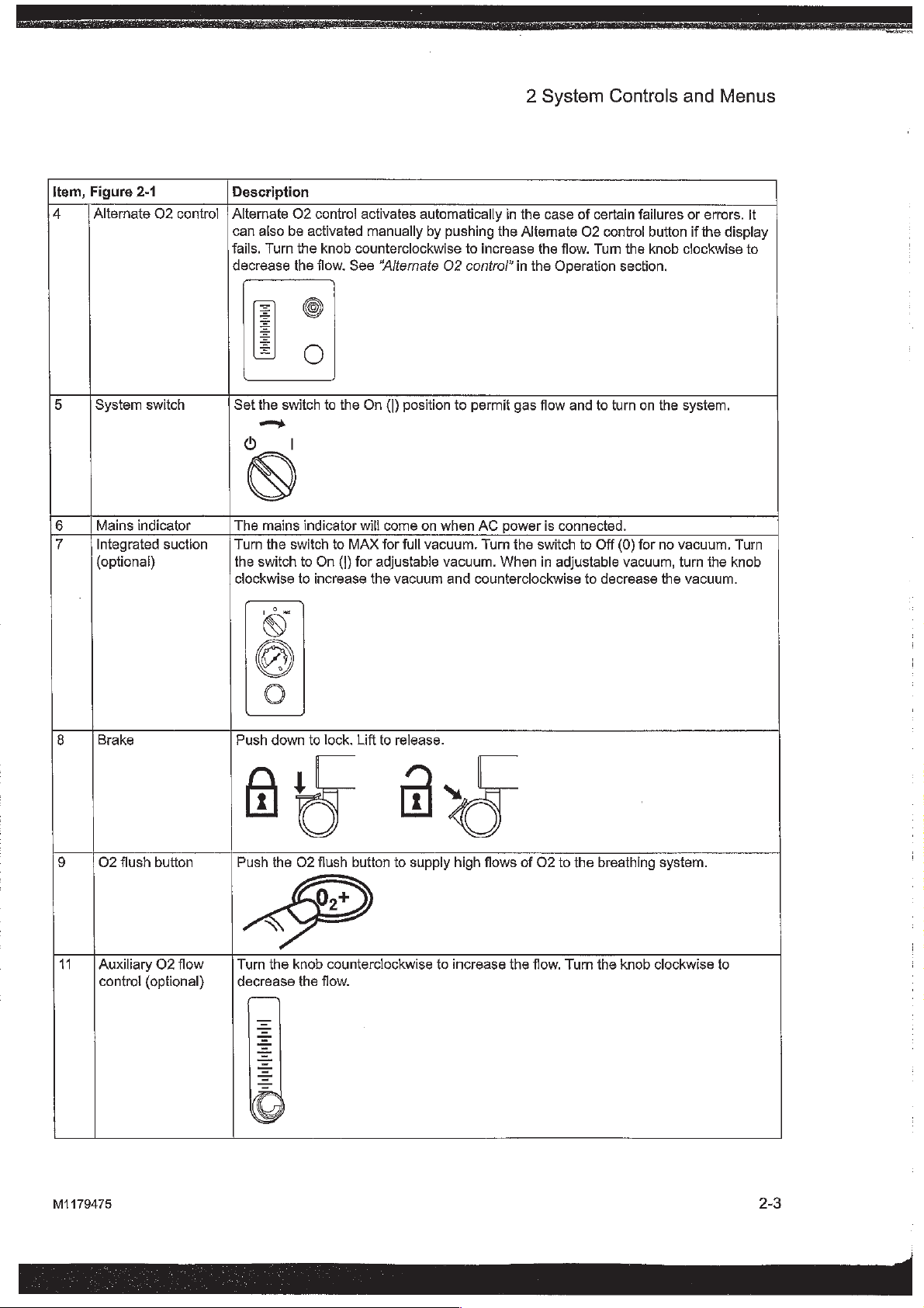
Alternate
System
Mains
Integrated
{optional}
switch
indicator
Description
O2
control | Alternate
can
fails.
decrease
Set
O
The
suction | Turn
the
clockwise
02
also
be
Turn
the
switch
—
I
mains
the
switch
switch
contro!
activated
the
knob
the
flow.
to
the
indicator
to
to
On
(])
to
increase
activates
manually
counterclockwise
See
On
will
MAX
for
the
automatically
by
“Alternate
(|)
position
come
on
for
full
vacuum.
adjustable
vacuum
pushing
O2
when
vacuum.
and
2
in
the
the
Altemate
to
increase
control"
to
permit
AC
Turn
counterclockwise
in
gas
power
the
When
the
the
switch
System
case
of
O2
flow.
Operation
flow
and
is
connected.
to
in
adjustable
to
Controls
certain
failures
control
Tum
the
section.
to
turn
on
Off
(0)
for
vacuum,
decrease
and
Menus
or
errors.
button
if
the
display
knob clockwise
the
system.
no
vacuum.
turn
the
vacuum.
the
Turn
knob
It
to
8
Brake
Push
down
IO
9
O2
flush
button
11
Auxiliary
control
O2
flow
(optional)
Push
the
<
Turn
the
decrease
to
lock.
Lift
to
y
LE
release.
a
uy
02
flush
button
to
supply
0,+
knob
counterclockwise
the
flow.
M
high
to
increase
flows
the
of
02
flow.
to
the
Turn
breathing
the
system.
knob clockwise
to
M1179475
2-3
Page 23
i
~
Aisys
TT
ET
QU
QU
UT
EU QU EU AT
ET
ET
ET
EU
EU
EU
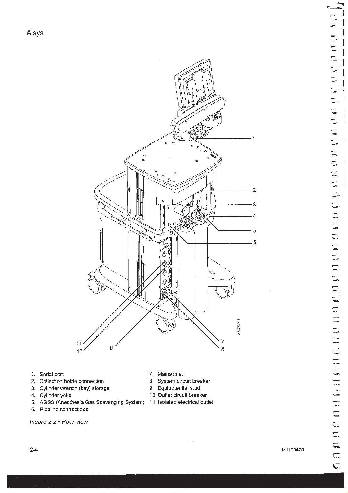
Serial
port
Collection
Cylinder
Cylinder
Bon
AGSS
Pipeline
Sa
bottle
connection
wrench
yoke
(Anesthesia
connections
(key)
storage
Gas
Scavenging
7.
8.
9.
10.
System)
11.
Mains
inlet
System
Eguipotential
Outlet
Isolated
circuit
stud
circuit
breaker
electrical
EU
LE
QU
EU
ET
LU EU
AB.75.046
san
breaker
outlet
Figure
2-4
2-2 * Rear
view
M1179475
noananant
Page 24
2
System
Controls
and
Menus
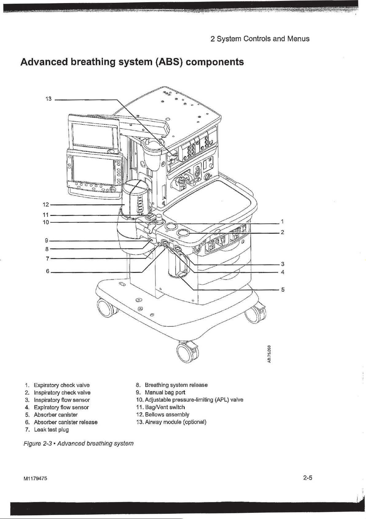
Advanced
13
breathing
system
00;
000
00
(ABS)
components
2
1.
Expiratory
2.
Inspiratory
3.
Inspiratory
4.
Expiratory
5.
Absorber
6.
Absorber
7.
Leak
test
check
valve
check
vaive
flow
sensor
flow
sensor
canister
canister
plug
release
8.
Breathing
9.
Manual
10.
Adjustable
11.
Bag/Vent
12.
Bellows
13.
Airway
system
bag
switch
assembly
module
release
port
pressure-limiting
(optional)
(APL)
valve
3
4
5
2
Figure
M1179475
2-3 « Advanced
breathing
system
2-5
4
Page 25
Aisys
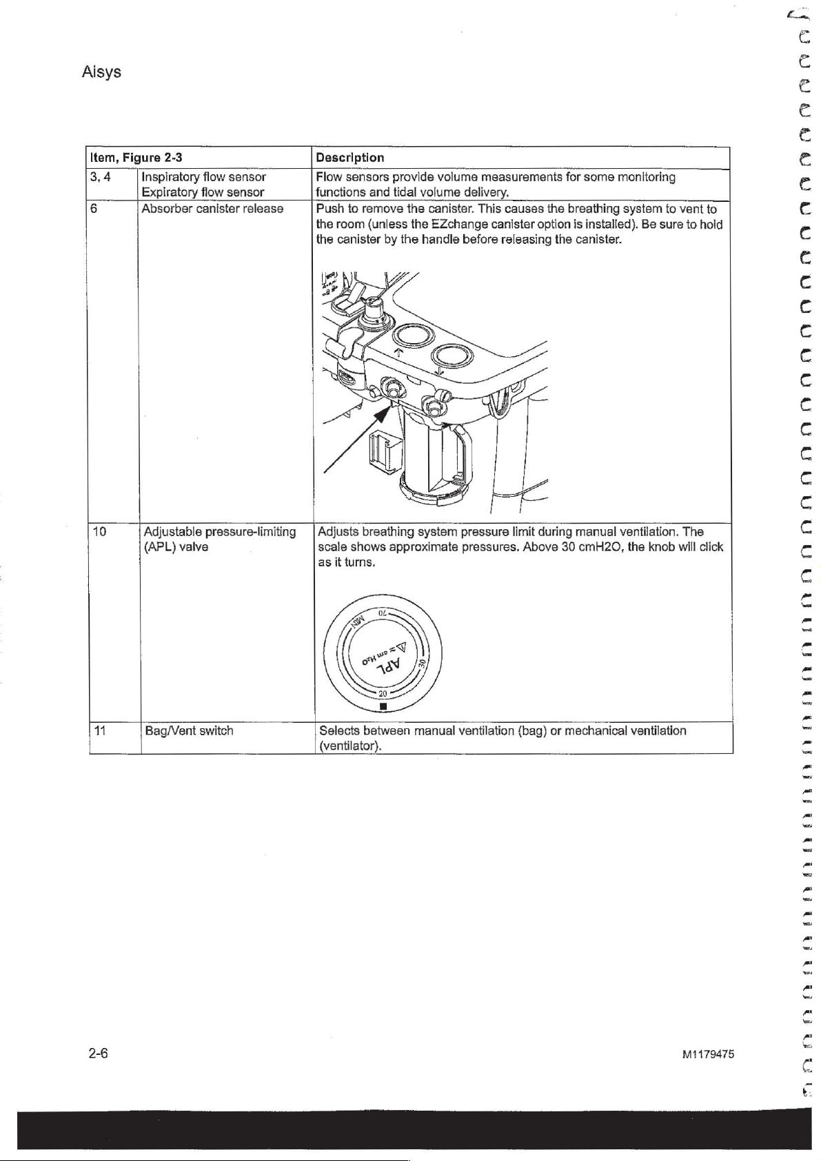
Item,
3,4
6
Figure
2-3
Inspiratory
Expiratory
Absorber
flow
sensor
flow
sensor
canister
release
Description
Flow
sensors
functions
Push
the
the
and
to
remove
room
{unless
canister
provide
tidal
the
the
by
the
volume
volume
canister.
EZchange
handle
measurements
delivery.
This
causes
canister
before
releasing
for
the
breathing
option
the
some
monitoring
system
is
installed).
canister.
Be
to
sure
vent
to
to
hold
10
11
Adjustable
(APL)
Bag/Vent
pressure-limiting
valve
switch
Adjusts
scale
as
Selects
(ventilator).
shows
it
turns.
breathing
approximate
between
system
manual
pressure
pressures.
ventilation
limit
(bag)
during
Above
manual
30
cmH20,
or
mechanical
ventilation.
the
ventilation
knob
The
will
click
2-6
M1179475
ranannananannnananninnanannnannannanaanannainananccoso
Page 26
2
System
Controls
and
Menus
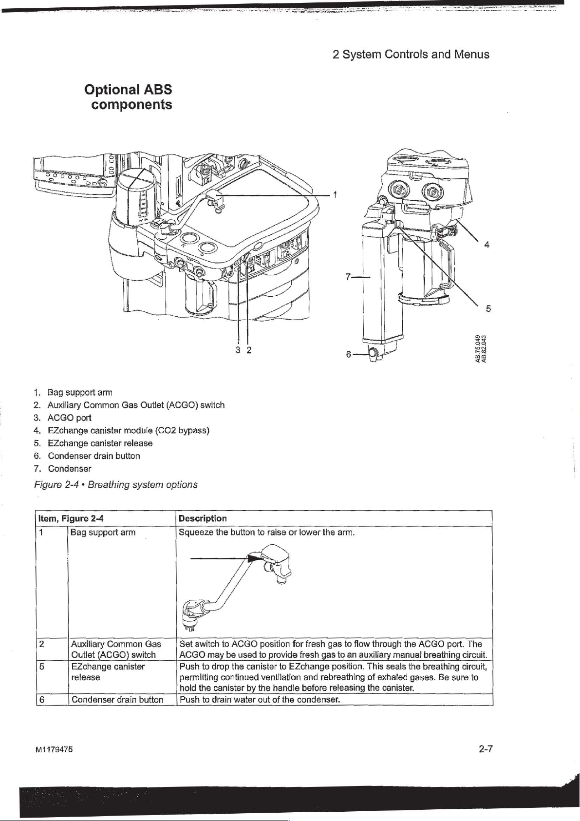
Optional
components
ABS
AB.75.049
AB.82.043
>
Bag
support
Auxiliary
ACGO
ON
EZchange
EZchange
Condenser
Noa
Condenser
Figure
2-4 + Breathing
Item,
Figure
1
2
5
6
Bag
Auxiliary
Outlet
EZchange
release
Condenser
Common
port
canister
canister
drain
2-4
support
arm
button
Common
(ACGO)
canister
drain
Gas
Outlet
module
release
system
arm
switch
button
(CO2
Gas
(ACGO)
options
switch
bypass)
Description
Squeeze
Set
ACGO
Push
permitting
hold
Push
the
switch
may
to
drop
the
canister
to
drain
button
to
ACGO
be
used
the
canister
continued
by
water
to
raise
or
position
to
ventilation
the
out
for
provide
to
EZchange
handle
of
the
condenser.
lower
fresh
fresh
gas
and
rebreathing
before
the
arm.
gas
to
to
an
position.
releasing
flow
through
auxiliary
This
of
exhaled
the
canister.
manual
seals
the
ACGO
the
gases.
port.
breathing
breathing
Be
sure
The
circuit.
circuit,
to
M1179475
2-7
Page 27
Aisys
Non-circie
WARNING
circuit
Fresh
gas
flow
through
This
absorbent
ventilation
volume
O2
non-circle
cell
Fresh
alarm
may
external
circle
Systems
circuit
Do
not
ventilation.
The
to
the
inspiratory
fresh
gas
capability
is
monitoring
monitoring
circuit
monitoring
gas
oxygen
limits
appropriately. Note
not
reflect
O2
circuit.
with
O2
value
not
use
an
use
the
non-circle
maximum
27
kPa
relief.
is
diverted
source
not
available
is
of
fresh
if
the
option.
concentration
FiO2
monitor
both
an
obtained
external
pressure
(4
psi).
around
port
may
(for
example,
when
not
available.
gas
system
when
when
using a rebreathing
airway
from
ventilator
circuit
the
when
non-circle
be
used
using
is
available
has
the
is
that
using
these
module
the
when
to
drive
at
the
inspiratory
with
Mapleson
the
airway
displayed
fresh
and
airway
using
external
non-circle
Use a breathing
check
ventilation
circuits
automatically
types
without
variants).
non-circle
module
on
the
gas
oxygen
of
circuits.
circuit
an
O2
cell
module.
the
non-circle
ventilators
circuit.
when
option
screen.
with
will
circuit
circuit
with
valve
and
out
is
selected.
CO2
Mechanical
Tidal
using
the
or
the
O2
Set
the
concentration
Use
an
the
non-
display
or
can
the
circuit.
for
Do
jet
be up
pressure
M1179475
Page 28
2
System
Controls
and
Menus
ACGO
(optional)
WARNING
Fresh
gas
(ACGO)
ACGO
operating
ACGO.
the
available.
The
ACGO
Do
with
Volume
through
the
02
is
monitoring
in
on
fresh
amount
Fresh
alarm
may
circuits.
on
position.
an
The
external
Bag/Vent
or
not
use
fresh
and
the
patient
monitoring
selected
the
breathing
the
pressure
gas
diverted
gas
limits
not reflect
Use
ACGO.
Systems
circuit
Do
to
O2
not
use
drive
with
external
flow
is
directed
the
front
of
the
Mechanical
auxiliary
Bag/Vent
circuit.
manual
switch,
Volume
switch
any
breathing
these
gas
controls
from
the
pressure
system
using
of
if
the
system
option. A sample
system. The
in
flow
rate
to
oxygen
appropriately.
FiO2
an
external
both
value
obtained
an
external
ventilators
when
other
fresh
gas
the
external
to
the
the
02
concentration
during
an
airway
ventilator
through
machine
and
the
when
ventilation
breathing
APL
valve,
and
pressure
the
APL
circuit
when
ACGO.
monitoring
using
methods.
is
available
has
the
airway
of
the
fresh
sample
circuit.
auxiliary
cell.
Note
O2
from
breathing
is
displayed
that
spontaneous
monitor
module
the
airway
on
the
or
for
jet
Auxiliary
is
circuit
connected
Common
the
ACGO
not
available
with
fresh
and bag
monitoring
valve
arm
do
to
switch
when
are
are
not
the
using a breathing
Patient
are not
the
automatically
module
flow
The
fresh
if
using a rebreathing
and
ACGO.
ventilation.
injury
ACGO
option
gas
is
diverted
to
the
O2
sample
circuit
on
the
gas
oxygen
breathing
an
02
module.
Do
may
available
port.
when
or
cell
flow
equal
screen.
concentration
or
in
cell
will
not
use
Gas
Outlet
is
in
the
gas
from
the
not
part
not
control
the
AGCO.
circuit
occur.
Monitor
the
ACGO
the
O2
cell
to
the
O2
cell
is
dependent
reduces
to
rebreathing
display
the
the
Set
the
circuit
on
the
the
ACGO
of
ACGO
M1179475
WARNING
Scavenging
sample
the
flow
The
maximum
(8
psi).
Use a breathing
A
sample
cell
This
breathing
scavenging
room.
1.
2.
3.
of
in
the
breathing
sample
circuit
To
connect
Attach a circle
ports.
Occlude
leak
test
Check
pressure
the
fresh
flow
should
is
is
not
the
breathing
plug
for
clinically
gas
Is
diverted
system
used
connected,
the
breathing
located
to
be
scavenged
with
scavenging:
circuit
behind
correct
at
the
ACGO
circuit
N20
the
circuit
with
to
show
the
or
volatile
sample
to
by
connecting
the
expiratory
settings.
can
pressure
the
airway
O2
numerics
when
an
anesthetics.
flow
the
inspiratory
be up
module
auxiliary
is
emptied
and
the
Y-piece
port.
to
55
relief.
or
the
on
the
screen.
manual
If
into
the
expiratory
to
the
kPa
02
2-9
Page 29
A
i
q*
1
,
i
Aisys
Scavenging
auxiliary
breathing
from
manual
circuit
an
4.
Check
* — If
+
Scavenge
with
An
auxiliary
provides a female
(or a 30
breathing
exhaust
The
AGSS
the
extract
the
the
Bag/Vent
the
bellows
bellows
(Mechanical
is
set
Ifthe
Bag/Vent
valve
sample
AGSS.
the
N20
or
volatile
inlet
mm
-19
system.
flow.
auxiliary
units.
There
flow.
inlet
position
is
to
to
flow.
exhaust
of
the
Bag/Vent
switch
fills
slowly
full,
the
sample
ventilation
ACGO.)
switch
MIN,
and
attach a bag.
When
the
if
an
auxiliary
anesthetics.
is
available
connection
mm
male
Do
is a convenience
is a reservoir
connector)
not
use
for
with
these
is
set
with
flow
does
is
set
bag
active
30
to
the
is
capture
switch.
to
mechanical
sample
goes
to
not
start
when
to
the
bag
The
bag
full,
the
sample
manual
mm - 30
into
connectors
inlet
and
to
breathing
passive
the
auxiliary
the
exhaust
ventilation
flow.
When
the
AGSS.
the
mode,
mm
air
fills
AGSS
male
as
an
brake
flows
set
slowly
flow
outlet
the
ACGO
the
APL
with
goes
circuit
is
units.
connector
port
under
for
of
active
higher
mode,
switch
the
to
the
used
It
the
than
Ch
cr
ch
egy
1
1
yay
3
va
4
ay
4
yay
KE
E
Scavenging
monitor
sample
a
gas
flow
A
separate
breathing
Sample
gas
・
gas
return
To
scavenge
port,
port.
To
scavenge
from
underneath
exhaust
circuit
to
from a gas
port
or
connect
the
monitor
the
hose
is
the
disposal
monitor
the
AGSS.
from a gas
the
tubing
from a gas
to
the
breathing
needed
point
can
monitor
from
the
monitor
male
luer
system.
from
the
for
all
be
scavenged
using
monitor
using
inlet
on
auxiliary
AGSS
the
sample
to
the
the
AGSS,
the
bottom
manual
units.
using
gas
sample
connect
of
the
sample
return
gas
the
return
tubing
AGSS
006
00000000
2-10
M1179475
i
|
0000000000
L
€)
Page 30
2
System
Controls
and
Menus
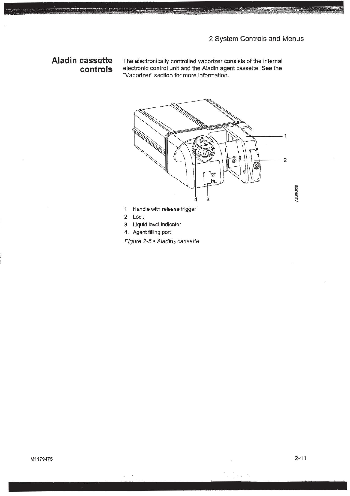
Aladin
cassette
controls
The
electronically
electronic
“Vaporizer’
1.
2.
3.
4.
Figure
control
Handle
Lock
Liquid
Agent
with
level
filling
2-5 « Aladino
controlled
unit
section
release
indicator
port
and
the
for
more
trigger
cassette
vaporizer
Aladin
information.
consists
agent
of
the
internal
cassette.
See
the
8
8
a
<
M1179475
2-11
Page 31

|
j
+
{
Aisys
Display
controls
,
091
nananaaanaaadocpop
000
1.
2,
3.
4.
5.
8.
(ko)
Silence
Menu
ComWheel
Normal
Quick
o
Timer
MV/TV
N
Alarm
Alarms
keys
Screen
keys
keys
Alarms
LEDs
key
key
key
Push
suspend/acknowledge
silenced
Push
Push
to
scroll
Push
Push
to
make a change.
Push
Push
Turn
to
silence
for
120
to
show
corresponding
to
select a menu
menu
items
to
remove
to
change
to
start
or
to
turn
off
on
solid
or
о
any
active,
silenceable
any
non-active
seconds
all
corresponding
stop
the
flash
item
or
change
menus
Push
the
MV
and
to
or
alarm
or
from
the
timer.
TV
indicate
ФФ
high
and
medium
is
suspended
menu.
confirm a setting.
settings.
the
screen.
gas
setting
or
ComWheel
Push
alarms.
alarm
to
activate
to
reset
Push
priority.
the
medium
or
high
priority
for
90
seconds.
Turn
clockwise
ventilator
again
the
timer
to
setting.
change.
back
turn
©
priority
alarms
alarms.
or
Turn
to
zero.
the
MV
{00
し
|
or
to
Alarm
is
counterclockwise
the
ComWheel
and
TV
alarms
AB.75.099
on.
Figure
2-12
2-6 * Display
controls
M1179475
000000000000000000000000000
Page 32

2
System
Controls
and
Menus
Anesthesia
2 3
SX
q
Measured
1:42
=
1
10
5
내
1
AE
0.5
Emo
Lo
0.00
i
Fresh
rá % :
Gas:
02
50
02+Air
system
=
havli
IAgent
9
p
e]
0
coz
.
Total
E
:
0
Flow
min
y
display
|
Des
%
TV
mi
ekimi.
ntila
RR
[min
A
PEEP
cmH20
4
LJ
5
Timer:
00:00:27
cmH2O
Ppeak
29
PEEP
6
в
%
*
0.0
MAC
40
|
0.0
[그
*|
eco
%
70 70
0 . 0
E102. % FO2 % |
L
10
Exp
MV
3.0
100
75 1 00!
Flow
min
:
6
12:27
Γ
Pmean
12
RR
10
Fl
%
0.0
ROZ
0.0
TVexp
?
:
min
4
È .
ml
7
I
13
9
|:
100)
100
1.
Split
screen
2.
Alarm
3.
Alarm
4.
Waveform
5.
General
6.
Clock
7.
Battery
8.
Measured
9.
Pipeline
Ventilator
10.
11.
Ventilation
12.
Gas
settings
Figure
M1179475
2-7 « Normal
|
area
silence
symbol
message
fields
message
indicator
values
and
cylinder
settings
mode
6.00
12
showing
fields
field
field
field
and
supply
view
electronic
countdown
or
timer
|
or
Off
field
respiratory
gas
11
flow
data
1/675
|
10
indicators
or
digit
10
field
|,
6
6.5%
|
6.57
645%
|
9
645%
8
E
q
2-13
Page 33

Aisys
When a menu
indicators
and
key
is
the
waveform
selected,
fields
the
menu
start
field
at
the
overlays
right
edge
the
of
gas
the
flow
menu.
„
e
=
©,
Е.
E.
21
A
|
i
1
I
1
Fresh
a
Menu
1.
2.
Waveform
Figure
2-8 * Menu
Gas:
O2+Air
02
%
100
fields
view
i
Total
Flow
“mi
6.00
6
Off | 675
È
D
ik
PO
TV
mí
2
ntilator
On:
RR
{min
|
10
CI
С.
1
Ppeak
cmH20
12:27
:
Pmean
CI
С.
G
|
I
CI
29
PEEP
Et:%
MAC
0.0
EICO2
0.0:
‘
PEEP
cmH20
6
Et02
||
100 £ 1005
xp
MV
|
6.577
6
40
©
%
%
100
Flow
limi
ως
*
12
RR:
min
1:
%
FI
FICO?
70
0.0
FiO2
TV
ων
.
645%
3
%
70
%
100]
:
|
4000]
5
8
<
C
G
I
,
=!
—
TI
Gr
I
=
I
=
!
<
1
<
1
..
=|
<
I
n
=
|
—
=
|
e
|
ーー
=
|
=
|
一
va
=
|
2-14
M1179475
~
Neer
~
~
ur
=
~
—
=
|
一
7
=
=
=
~
=
=
=]
~
|
|
|
|
|
|
|
|
|
|
|
|
Page 34

2
System
Controls
and
Menus
Waveform
Digit
fields
field
Up
to
three
waveforms
Each
waveform
agent,
flow,
or
shows
waveform
that
When
screen
waveforms
from
in
the
measured
is
set
waveform
one
waveform
corresponding
view.
The
to
fill
the
waveform
and
the
normal screen
size
and
is
centered
See “Screen
information.
The
digit field
supply,
airway
Paw,
O2,
case.
If
display,
parameter.
configuration’
flow,
or
module
and
any
of
the
digit field
can
be
CO2
data.
to
show
and
numeric
is
numerics
remaining
area.
the
corresponding
in
can
be
set
agent.
is
either
these
If
inserted,
TVexp
parameters
information
can
be
shown
set
to
show
The
corresponding
values
turned
view.
the
field
the
agent
areas
off,
information
waveforms
When
two
The
waveform
in
the
to
show
the
digit
field
the
area
or
CO2
is
on
the
normal screen
specific
to
and
are
that
are
waveforms
numerics
remaining
“Operation”
specific
is
must
not
is
replaced
information
the
right
no
airway
blank.
waveform
removed
and
numerics
area.
information
is
set
to
blank.
show
selected
numeric
information
waveform
with
of
the
waveform.
module
and
from
are
turned
section
show
agent
on
the
to
show
the
view.
such
as
Paw,
information
If
is
inserted,
the
the
normal
increase
increases
for
such
display
missing
off,
are
more
as
and
on
in
those
removed
gas
no
during
the
the
size
in
a
See
“Screen
information.
configuration”
in
the
“Operation”
section
for
more
M1179475
Page 35

Aisys
Using
menus
|
sa?
qt
er
a
Push a menu
ComWheel
Menu
title
Current
Adjustment
Submenu
Instructions
Menu
οσον."
Figure
selection
items
2-9 » Menu
key
to
navigate
window
or
help
to
display
the
information
example
the
corresponding
menu.
N
AB.91.126
menu.
Use
the
ar
gy
hgh
gh ay
ay
gt
ay
QV
4)
ο
2-16
2.
3.
4.
Push
the
Turn
the
item.
Turn
menu
item.
Push
the
submenu.
Turn
the
the
desired
Push
the
Select
the
Previous
Normal
menu
menu
key
ComWheel
the
ComWheel
ComWheel
ComWheel
selection.
ComWheel
Screen
and
return
Menu
to
to
display
counterclockwise
to
clockwise
to
to
return
the
clockwise
enter
the
confirm
or
push
the
normal
to
the
corresponding
adjustment
or
counterclockwise
the
the
monitoring
last
to
highlight
to
highlight
selection.
Normal
displayed
Screen
menu.
the
the
previous
window
to
display.
menu,
next
menu
or
a
highlight
key
to
exit
(Select
if
available.)
M1179475
NNN
ONO
bar
Page 36

3
Operation
In
WARNING
this
section © Turning
_
Ventilator
alarms
adequate
Maintain
Desiccated
dangerous
anesthetics.
ensure
when
Start
End
case..............................,,....,,..
Ventilator
Gas
Spirometry
alarms
that
occur
patient
sufficient
(dehydrated)
chemical
that
finished
on
the
case
(start
setup.............,.....,.....,.....,...
setup
...........
...............,,.....,.....,........
indicate
should
safety.
fresh
reactions
Adequate
absorbent
using
the
system
gas
flow)...........................
potential
be
investigated
gas
flow
absorbent
precautions
does
not dry
when
when
hazard
using
material
exposed
should
out.
Turn
system.
.....................,....,..
aaa
conditions.
to
help
ensure
sevoflurane.
may
produce
to
inhalation
be
taken
off
all
All
to
gases
3-2
3-3
3-6
3-7
3-9
3-11
M1179475
Spirometry
Main
Screen
Аагт
Alternate
EZchange
Condenser(optional)
Passive
Active
setup.
..........,............,.....,..
Menu
...............,..,..................
configuration.
зефир...
AGSS
AGSS
...
O2
control
canister
(optional)
(optional)............................
ii
(optional)
............,.................
...................,..........
........,..........,...
.............................
..........................
3-14
3-16
3-20
3-23
3-26
3-27
3-28
3-29
3-30
3-1
Page 37

Aisys
Turning
on
the
system
1.
Plug
system
+
・
1.
System
2.
Mains
Figure
the
power
circuit
The mains
Battery
3-1 + Mains
is
2
switch
indicator
cord
into
breaker
indicator
charging
indicator
an
is
on.
is
if it
and
lit
is
electrical
when
not
system
outlet.
AC
power
already
switch
Make
is
fully
charged.
sure
the
connected.
1
AB.91.044
et
ET at at
EU ET
EU
EU
EU
ET QU EU
EU
EU
EN
CAUTION
Note
2.
Check
Do
not
port
3.
Turn
»
+
4.
Perform a Machine
5.
Perform a preoperative
The
remaining
a
power-up
occurs.
resolve
that
the
turn
on
plugged.
the
System
The
display
The
system
“Preoperative
system
on.
Turn
the
must
If
the
Self
test,
the
alarm.
the
Checkout”
perform a power-up
power
breathing
system
switch
shows
does a series
system
the
the
Check
checkout
has
‘Turn
off
and
system
with
to
On.
power-up
section.
power
the
of
before
been
then
back
is
properly
right-hand
screen.
automated
the
first
before
on
Off
each
self test
longer
and
On
on
between
connected.
(inspiratory)
self
tests.
case
of
the
case.
after
12
hours
than
12
hours
for
self
cases
day.
See
the
tests’
to
of
without
alarm
EU
EU
VEN
{
3-2
M1179475
побои
Page 38

3
Operation
Start
case
(start
gas
flow)
Access
by
Case
The
case
slot
Case
menu.
or a service
information
the
Start
selecting
menu
to
Start
Default
Patient
Set
Vent
By
Patient
Other
CO2
Volume
Start
Case
Default
types.
The
shows
as
types
The
Install/Service
on
Case
Start
Case
set the
Case
Settings
Weight
Weight
Age
Gas
Alarms
Apnea
Now
Settings
fifth
the
default
are
configured
person.
the
Start
menu
by
from
the
case
data
has
five
selection
when
in
the
menu
See
the
“Super
Case
pushing
Checkout
and
selections.
is
Last
the
Install/Service - Case
is
menu
the
to
start
The
Case.
Start
Case
only
accessible
User
Mode”
defaults.
Start/End
menu.
the
first
The
menu
Use
gas
flow.
four
case
by a Super
section
Case
key
the
Start
selections
type
in
the
is
opened.
Defaults
for
more
or
are
first
User
Note
WARNING
The
values
Apnea
602
opened.
Volume Apnea
Volume
menu.
The
ventilation
rate
The
Weight
Make
of
are
configured
Alarms
Apnea
Set
Vent
mode
and
tidal
Default
is
selected.
sure
setting
Settings
that
assembled
appropriate
circuit
injure
assembly
the
patient.
Patient
is
is
not
Selection
By
Weight
is
set
volume
the
and
that
before
and
Weight,
to
set
shown
to
calculations
selection
patient
starting
Patient
the
default
to
‘On’
on
the
is
set
to
menu
item
VCV
or
PCV-VG.
shows
breathing
the
ventilator
ventilation.
when
based
incorrect
Age,
Other
case
type
by
the
Start
Start
Case
Disable
is
in
the
accessible
Use
on
the
‘Weight’
circuit
settings
Incorrect
ventilator
Gas,
and
Volume
the
Super
User.
Case
menu
menu
when
the
Install/Service
when
the
this
set
when
are
setting
patient
for
weight.
Set
Vent
is
correctly
clinically
breathing
settings
can
is
breath
By
M1179475
Page 39

Aisys
Using
Using
default
settings
customized
settings
Set
the
2.
Push
the
*
The
*
The
3.
Verify
4.
Select
The
case
type,
and
gas
settings
Vent
Setup
change
case.
additional
1.
2.
3.
4.
5.
6.
settings
Return
Set
the
Push
the
Verify
*
Select a case
+
Make
case.
・
The
any
To
change
»
Push
*
Select
*
Change
*
Select
*
Make
*
Select
make
To
change
ㆍ
Push
ㆍ
Select
・
Change
*
Select
To
change
*
Push
*
Select
*
Select
return
Bag/Vent
Start/End
case
Default
or
change
Start
menu,
to
adjustments
Bag/Vent
Start/End
or
change
adjustments
Default Settings
changes
the
any
additional
the
the
switch
defaults
Settings
the
Case
Now.
ventilator
can
be
Alarm
not
shown
the
Start
or
switch
the
type
to
the
the
alarm
Alarm
Adjust
Back.
Previous
ventilator
Adjust
Exit
the
the
Confirm
to
Settings.
the
settings.
other
Vent
Setup
Settings.
the
settings.
to
return
ventilation
Vent
Setup
desired
the
Start
to
Bag.
Case
key.
are
shown
selection
settings
settings,
changed
Setup
Case
to
Case
settings
settings:
Setup
changes
Menu
adjustments.
settings:
on
the
Gas
flow
ventilation
before
menu,
on
the
Start
menu
start a case.
to
Bag.
key.
on
the
or
Last
Case
to
the
other
selection
settings
to
key.
to
to
return
key.
the
mode:
are
the
Start
key.
mode.
or
adjust
the
Case
menu.
on
the
menu.
shows
starts.
from
settings
settings
the
Start
Case
mode,
starting a case.
or
Gas
Setup
Case
menu
these
menus
Start
Case
from
the
as
changes
made.
alarm
setup.
to
the
Start
Case
menu.
and
preset
Default
appropriate
to
select
menu.
alarm
menu
before
to
menu.
show
Case
case
settings,
Use
starting
make
Settings.
‘Preset’
menu
Confirm
type.
the
to
for
a
the
if
to
to
3-4
M1179475
enannananannananannnnananananaananananaaaanar
Page 40

7.
To
*
*
+ © Change
*
8.
To
+
*
*
9.
To
*
*
*
10.
From
starts.
change
Pushthe
Select
Select
change
Push
Select
Select
the
Start
change
Push
Select
Select
return
the
the
gas
settings:
Gas
Setup
Adjust
Exit
the
the
the
Exit
the circuit
the
the
Confirm
to
Start
the
settings.
to
balance
Gas
balance
or
Case
Gas
circuit
the
Start
Case
Settings.
return
Setup
adjust
Setup
to
gas:
gas
menu.
type:
type.
or
adjust
Case
menu,
key.
the
key.
to
the
settings
key.
menu.
select
Start
use
the
settings
Case
with
and
Start
menu.
02.
select
and
select
Case Now.
3
Operation
Exit
to
Confirm
Gas
return
flow
i
to
to
Minimum
Concentration
Alveolar
(MAC)
The
adjusted
based
on
default
patient
entered.
The
MAC
the
related
patients
resulting
on
of
The
including
gases
dashes
have
the
Eger
each
agent
adjusted
digit
if
Minimum
the
patient
age
of
value
is
calculated
affects
in a higher
in
field,
there
based
better
formula.
are
added
MAC
the
mini-trend,
and
is
not
value
Alveolar
age entered
selected
liver
MAC
When
graphical
an
case
from
on
the
age
function
value.
two
agents
together.
shows
agent
trends
airway
module
Concentration
in
the
Start
type
the
exhaled
of
the
and
can
The
MAC
are
The
MAC
on
several
waveform
page.
installed
(MAC)
Case
is
used
if
gas
patient.
clear a drug
calculation
detected,
value
areas
numeric
MAC
in
is
calculated
menu.
no
concentration
Typically,
range
of
data
the
The
patient
the
the
information,
younger
faster,
used
is
MAC
is
0.0
screen
shows
module
age
based
values
as
is
and
to
9.9.
bay.
|
|
|
|
|
|
M1179475
3-5
Page 41

Aisys
End
case
Use
the
End
Normal
End
End
Case
Case
Case
Screen
menu
Now
to
stop
gas
flow
and end
the
patient
alarms.
=
qr oy
Y
a
Ce:
©
wr
Set
Push
Select
flow
Bag/Vent
the
the
Start/End
End
and
patient
Case
Now
to
Case
to
switch
alarms).
Bag.
key.
put
the
system
in
standby
(stops
~
gas
M1179475
Page 42

3
Operation
Ventilator
setup
Access
system
*
*
・
*
・ — Synchronized
*
Adjust
Mode:
VCV
PCV
SIMV/PSV
PSVPro
SIMV-PC
PCV-VG
Spirometry
Normal
the
Vent
has
up
to
Volume
Pressure
Synchronized
Support
Pressure
Control
Pressure
(optional).
Control
Control
(SIMV/PSV)
Support
(SIMV-PC)
Control
Vent
Settings
Screen
Setup
Setup
menu
by
six
modes
Ventilation
Ventilation
Intermittent
Intermittent
Ventilation-Volume
of
mechanical
(VCV).
Mandatory
(optional).
Ventilation
Mandatory
(optional).
pushing
(POV)
(optional).
(PSVPro)
the
Vent
Setup
ventilation:
Ventilation/Pressure
(optional).
Ventilation-Pressure
Guaranteed
key.
(PCV-VG)
The
Using
WARNING
Important
quick
A
keys
Most
anesthetic
reduced
hypoxemia.
not
The
patient’s
ventilatory
produce
use
of
neuromuscular
breathing
Therefore,
triggering.
Refer
to
the
“Specifications
more
information
The
main
ventilator
using
the
ventilator
1.
Push a ventilator
setting.
Turn
the
ComWheel
Push
the
ComWhee!
agents
responses
adequate
response,
on
ventilation
settings
quick
quick
to
will
cause
to
triggered
modes
ventilation.
blocking
which
and
Theory
modes.
for
each
mode
keys.
key
to
select
make a change.
to
activate
(confirm)
patients
carbon
dioxide
of
agents
will
interfere
of
Operation”
can
easily be
the
corresponding
the
to
have
and
to
ventilation
will
reduce
may
with
section
change.
for
changed
ventilator
the
en
M1179475
3-7
e
Page 43

Απ.
αν
Aisys
Using
Changing
modes
Vent
Setup
menu
ventilator
and
settings
Push
the
*
Adjust
>
An
arrow
Push
the
selected
Use
the
ComWheel
change a value.
Push
the
Push
the
一
Push
the
N
Select
window.
change
Select
Use
the
the
ComWheel
a
Confirm
Vent
Setup
Settings
to
the
ComWheel
mode.
ComWheel
Normal
Vent
Setup
mode
and
value.
to
key.
is
selected
right
of
to
enter
to
navigate
to
activate
Screen
key.
push
the
to
navigate
activate
the
mode
the
the
the
key
or
ComWheel
the
the
mode.
by
default.
indicates
adjustment
adjustment
change.
select
Exit.
to
adjustment
the
window
window
enter
the
window
current
mode.
for
the
and
adjustment
and
OO
OOO
to
to
OT
OU
OO
OO OO
€
OO
0
3-8
M1179475
1000900000
f
raagae
Page 44

3
Operation
Gas
setup
Using
quick
keys
Access
the
balance
Adjust
Gas:
N20
Air
Circuit:
Circle
Non-Circle
Normal
The
keys.
1.
2.
3.
the
Gas
Gas
Setup
gas,
Gas
Settings
Screen
02%
and
Push a gas
Turn
the
Push
the
and
Setup
total
ComWheel
ComWheel
Setup
menu
to
change
flow
quick
menu
by
to
adjust
the
can
easily
key
to
select
to
make a change.
to
activate
pushing
the
02%
circuit
be
the
(confirm)
the
Gas Setup
and
total
flow,
type.
changed
corresponding
using
the
change.
to
the
gas
key.
Use
change
gas
quick
setting.
the
Using
Changing
Gas Setup
menu
gas
and
settings
1.
Pushthe
+
An
arrow
currently
ㆍ
Adjust
Push
the
Use
the
change a value.
Push
the
Push
the
=
Push
the
Select
N
to
3.
Use
change a value.
enter
Push
Push
the
the
the
the
Gas
Setup
to
the
being
Settings
ComWheel
ComWheel
ComWheel
Normal
Gas
Setup
balance
the
adjustment
ComWheel
ComWheel
Normal
key.
right
used
is
selected
to
enter
to
navigate
to
activate
Screen
key.
gas
to
window.
to
navigate
to
activate
Screen
of
the
with
key
use
key
balance
O2.
by default.
the
adjustment
the
adjustment
the
change.
or
select
with
O2
the
adjustment
the
change.
or
select
gas
Exit.
and
Exit,
indicates
window.
window
push
the
window
the
gas
and
ComWheel
and
E
M1179475
3-9
Page 45

Aisys
ーー
Changing
circuit
type
1.
Push
・
+
2.
Use
adjustment
3.
Confirm
Push
the
Gas
Adjust
An
currently
the
afrow
ComWheel
or
the
Normal
Settings
window.
change
Setup
to
the
in
use.
Screen
key.
is
selected
right
to
select
and
confirm
of
the
circuit
Circle
the
key
or
by
default.
type
or
Non-Circle
settings.
select
indicates
Exit
the
and
circuit
enter
the
っ
7
Y
к’
4’
4
41
41 4:
gl gi «)
Ol
AT EU
di
a
em
|
=
|
=.
|
πα
|
=
|
=
|
m
|
一
=
|
m
I
I
|
I
TI
TI
σπα
3-10
M1179475
TI
σπα
πα
πα
1
1
J
Page 46

Spirometry
There
are
three
types
Fiow-Volume
spirometry
Access
Use
the
+ © View a specific
type.
+
Adjust
*
Access
+
Store a loop
be
・
View a saved
the
・
Erase a saved
loop
Loop
Type
Scaling
Spiro
Setup
Save
Loop
Reference
Erase
Loop
Previous
(F-V)
loops
the
Spirometry
Spirometry
the
loop
the
Splrometry
saved.
loop
was
was
saved.
Spirometry
Loop
Menu
and
to
loop;
saved.
of
spirometry
and
Pressure-Flow
set
the
menu
menu
to:
loop
type;
scaling;
memory;
loop;
select
select
select
P-V
None
None
loops:
loop
scaling
by
pushing
select
Sealing
Setup
menu;
select
Save
Reference
Erase
Pressure-Volume
(P-F).
View,
in
the
the
Spirometry
Loop
Type
and
select
Loop.
Loop
Loop
and
3
Operation
save,
and
Spirometry
and
set
the
set
the
scale
Spiro
Setup.
Up
to
six
loops
and
the
time
the
time
at
(P-V),
erase
menu.
key.
loop
type.
can
at
which
which
the
M1179475
3-11
Page 47

Aisys
,
四
EŞ
-
O
Setting
loop type — The
to
show
Volume
.
BON
Figure
spirometry
alongside
Pressure
Real-time
Reference
3-2 * Example
loops
axis
axis
loop
loop
show
the
waveforms
(appears
of a P-V
in
on
display
the
spirometry
as
the
in
white)
loop
window
split
screen.
and
can
be
set
AB.98.039
加
A
A
O O O
O
Note
To
set the
1.
2.
The
the
Main
Setup - Loop
Push
the
Select
・
Set
・
Set
・
Set
loop
type
loop
Loop
Menu
type:
Spirometry
Type
to
P-F
for
Paw-Flow.
to
F-V for
to
P-V
can
Type.
Flow-Volume.
for
also
key,
and
key.
and
set
the
Paw-Volume.
be
set
in
the
select
Parameters
loop
type.
Spirometry
Setup
Setup - Spirometry
menu.
Push
ATACANTE
A
3-12
M1179475
5009000000
Page 48

3
Operation
Scaling
The
scales
menu.
The
axes
are
The
AUTO
axes
of
the
reading
The
flow
the
scale.
The
separately
shown
Linked
axes
remaining
/ndep
Previous
shown
available
dependent
selection
loop
of
selection
for
Scaling
Vol
Paw
Flow
in
graph
in
the
selection
the
loop
two
scales
the
volume,
Scaling
Scale
Scale
Scale
Menu
the
spirometry
settings
on
automatically
waveform.
links
graph
allows
AUTO
for
the
the
set
patient
based
on
the
the
adjustment
together.
automatically
the
axes
Paw,
and
loop
graph
volume,
type
adjusts
minimum
Change
change
of
the
flow
axes.
Paw,
of
the
of
the
loop
one
are
set
and
adult
or
volume,
and
maximum
volume,
of
the
based
graph
in
the
Scaling
flow
graph
pediatric.
Paw,
and
flow
breath
Paw,
and
scales
on
to
be
the
one
changed
and
set
Push
Select
Set
*
*
«
the
Sealing.
the
scale
lf
AUTO
If
Linked
flow.
|f
Indep
and
set
Spirometry
type
to
is
selected,
is
selected,
The
other
is
selected,
the
flow
key.
AUTO,
two
scales
set
scale.
Linked,
the
scales
set
one
adjust
the
or
are
of
the
based
volume
Indep.
automatically
scales
scale,
volume,
on
the
set
set
the
set.
Paw,
scale.
Paw
or
scale,
3-13
Page 49

Aisys
그
al
그
G
그
E
Spirometry
setup
Note
Push
the
Spirometry
Spirometry
»
Set
the
+
Select a data
・
Set
the
・
Change
MVexp
+
Set
split-screen
*
Access
The
Spirometry
-
Parameters
Spirometry
Patient
and
Previous
key
Setup
patient
loop
the
or
the
Sensor
Data
Split
MVexp
menu.
and
source.
type.
volume
TVexp.
Paw
Setup
Setup - Spirometry
Setup
Type
Source
Loop
Type
TV
or
Screen
Paw
Alarm
Alarm
Menu
sensor
shown
view.
and
menu
Adult
Vent
P-V
MV
TV
None
Use
MVexp
and
the
type.
on
is
select
Spiro
Spirometry
the
spirometry
alarm
limits.
also
accessible
Setup.
Setup
Setup
split
through
to
access
menu
screen
Main
the
to:
to
Menu
O
Setting
patient
sensor
and
type
Patient
the
module,
used.
If
not
1.
2.
3.
airway
the
sensor
be
Push
Select
Select
*
+
and
accurate.
sensor
module.
ensure
type
the
Spirometry
Spiro
Adult
Adult
refers
Pedi
refers
type
refer
to
If
spirometry
that
the
sensor
is
not
set
correctly,
key.
Setup - Patient
or
Pedi
depending
to
the
D-lite
to
the
Pedi-lite
the
style
data
is
type
matches
the
and
on
sensor.
sensor.
of
airway
obtained
the
information
Sensor
the
Type.
sensor
adapter
from
the
airway
displayed
used.
used
airway
adapter
may
with
O
€
LT
EO
LU
€) LU
LT
El
AAA
EL}
El
AA
En
A
El
A
EU
3-14
M1179475
Mo)
Er
EU
LÉ
A
E
Page 50

3
Operation
Selecting a data
source
Several
the
When
D-lite
If
installed,
displays
If
comes
sensor
the
Information
the
information.
Figure
monitoring
airway
the
information
associated
module
module.
setting
or
Pedi-lite
sensor
the
room
from
readings
3-3 « Airway
the
airway
sensor
is
not
waveform
air.
is
not
the
internal
disagree
alarm
that
is
data
indicator.
parameters
module
is
properly
properly
available
retrieved
module
connected,
shows
ventilator
with
occurs.
from
See
data
can
be
as
the
connected
no
flow.
through
sensors.
the
airway
the
the
“Airway
indicator
obtained
data
but
the
The
gas
the
airway
If
module
airway
Modules”
from
source,
on
the
airway
monitor
module,
the
internal
sensor
module
the
ventilator
make
sure
airway
module
samples
information
ventilator
readings,
is
identified
section
or
that
module.
is
and
with
for
more
a
Setting
split
spirometry
screen
Push
the
Select
3.
Select
+ — If
Patient
source
+
If
Vent
be
4.
Push
the
Spirometry
normal
1.
2.
3.
4.
screen,
Push
the
Select
Select
Pushthe
Spirometry
Spiro
Setup - Data
Patient
the
loops
Spiro
Split
or
is
selected,
for
information.
is
selected,
first
source
Normal
can
To
set
Spirometry
Setup.
Screen - Spiro.
Normal
key.
Vent
as
the
for
Screen
be
viewed
up
the
Screen
Source.
the
primary
the
airway
internal
information.
key
or
alongside
spirometry
key.
key.
source
module
sensors
select
the
split
for
information.
will
be
of
the
Previous
waveforms
screen:
the
first
ventilator
Menu.
on
will
the
M1179475
3-15
Page 51

Aisys
.
Main
Menu
FE
à
=
a
|
=
一
I
”
1
~
|
一
vet
1
Menus
Trends,
Screen
System
and
See
menu
See
information
See
calibrations.
and
settings
System
Setup,
Status
software
“Screen
item.
“Parameters
on
the
“User
Main
System
Cardiac
Fresh
Gas
Screen
Parameters
Calibration
Normal
available
Status,
Parameters
shows
settings.
configuration"
setup”
the
Parameters
Maintenance”
Menu
Trends
Status
Bypass
Usage
Setup
Setup
Screen
Cardiac
the
in
Off
through
Setup,
status
of
for
information
the
“Airway
Setup
section
the
Bypass,
and
Calibration.
gas
supplies,
Modules”
menu
for
more
Main
Menu
Fresh
on
Gas
electrical
the
Screen
section
item.
information
include
Usage,
: .
supplies,
Setup
for
more
on
wr
Gr
一
wr”
m
w
er
ーー
πα
--
ーー
κ
ar
“|
or
er
-一
“|
ey"
-一
er
ーー
πα
I
|
|
|
|
I
1
I
I
I
I
i
I
“1
o
I
=
1
πι
em!
I
ep
I
v
I
=
I
se
I
“1
πι
vi
“1
21
v
“1
vi
3-16
M1179475
v
v
Y
I
1
Page 52

3
Operation
Trends
There
are
three
views
for
patient trends:
settings,
the
Cursor
Next
View
Measured
Seitings
Graphical
Time
Previous
N
pe
and
most
recent
Page
Scale
Push
Select
ㆍ
An
Select
Push
Select
graphical.
Trends
Menu
the
Trends
the
desired
arrow
Cursor
the
ComWheel
Next
Trend
24
hours.
key.
view.
indicates
to
scroll
Page
to
information
the
current
through
to
return
view
additional
the
the
highlight
measured
is
saved
trend
view.
current
trend
to
parameters.
(numerical),
every 1 minute
view.
Cursor.
for
va
Push
the
Normal
Screen
key
or
select
Previous
Menu.
M1179475
3-17
Page 53

=
=
Aisys
Cardiac
Manual
cardiac
bypass
ventilation
bypass
WARNING
There
are
two
bypass
Manual
cardiac
The volume,
suspended.
off
Manual
bypass
receiving
is
standard.
ventilation
bypass
or
mechanical
ventilation
modes
The
extra-corporeal
heart-lung
intended
to
patient.
1.
Set
the
Bag/Vent
2.
Push
the
3.
Set
Cardiac
*
The
waveforms
ventilation
types
of
VCV
cardiac
when
the
apnea,
low
alarms
ventilation
cardiac
should
machine.
provide
switch
Main
Menu
Bypass
general
message
and
cardiac
cardiac
bypass.
cardiac
ventilator
agent,
are
bypass
CO2,
enabled
is
started.
bypass
bypass
only
be
oxygenation
These
modes
metabolic
to
Bag.
key.
to
On.
‘Cardiac
in
the
general
bypass
Manual
is
suspends
is
not
mechanically
and
respiratory
when
cardiac
and
used
of
levels
Bypass’
message
is
active.
ventilation
optional.
alarms
when
VCV
by
for
patients
ventilating.
rate
bypass
cardiac
the
patient
means
ventilation
of
ventilation
shows
field
in
when
cardiac
on
alarms
is
turned
is
of
a
are
not
to
the
the
manual
are
=
=
=
=
=
<
<
"a
a
y
e
a
o:
eo
=
©
on
VCV
cardiac
(optional)
WARNING
bypass
Systems
ventilate
mode
low
The
mechanical
Manual
bypass
receiving
with
while
available
agent,
alarms
CO2,
are
ventilation
ventilation
modes
extra-corporeal
heart-lung
intended
to
patient.
1.
Start
mechanical
Push
the
Set
Cardiac
+
The
*
TV
settings
bypass
*
TV
settings
bypass
・
PEEP
bypass
4.
The
general
waveforms
bypass
is
VCV
cardiac
in
VCV
mode.
while using
low
Paw,
enabled
is
cardiac
should
machine.
provide
ventilation
Main
Menu
Bypass
PEEPis
and
active.
set
of
remain
of
change
TV
mode.
message
and
in
less
settings
the
bypass
The
VCV
cardiac
and
respiratory
when
VCV
stopped.
bypass
only
oxygenation
These
metabolic
-
in
key.
to
On.
to 5 cmH20.
than
at
the
set
more
than
to
170
ml.
can
‘VCV
general
enabled
VCV
mode
cardiac
be
used
modes
levels
VCV
170
mi
TV.
170
ml
be
changed
Cardiac
message
can
mechanically
is
the
bypass.
rate
and
The
alarms
bypass
VCV
when
by
of
ventilation
of
ventilation
-
mode.
prior
to
starting
prior
to
starting
after
Bypass’
field
when
only
volume,
are
is
turned
cardiac
the
patient
means
entering
shows
VCV
ventilation
apnea,
suspended.
off
or
is
of
a
are
not
to
the
cardiac
cardiac
cardiac
in
the
cardiac
M1179475
<=.
Ce
一
Na
—
a
ーー
Nemi!
©
<.
<
©
<
=
一
~
©
ーー
ris
一
μον
Cr
=
Gr
e
o
一
ων
—
wo
=.
Page 54

Fresh
gas
usage
Use
the
N20,
shows
most
1.
Push
2.
Select
Select
3.
4
Push
Fresh
and
agents
for
gases
recently
the
Main
Fresh
the
the
Normal
Gas
Usage
used
available
used
agents.
Menu
Gas
patient
selection
for
the
on
key.
Usage.
case
to
Screen
three
the
system.
view.
key
to
view
most
or
select
the
recent
Agent
Previous
volume
cases.
data
shows
3
Operation
of
O2,
Air,
Data
only
the
three
Menu.
M1179475
Page 55

Aisys
Screen
configuration
Select
page
Each
case
type
corresponding
additional
menu.
views
Areas
information.
screen
Use
screen
are
of
the
normal
The
set
the
view.
Select
view
Select
Default
case
by
normal
Use
to a case
PAW
BIG
selected
screen
screen
type
screen
the
Super
screen
the
Screen
Page
menu
Page
Page:
Screen
TUBES
LOOPS
WAVE
LOCAL
on
the
Start
configuration
views
User
can
to
type
view.
for
are
available
configurations
in
the
be
customized
Setup
menu
quickly
Case
menu
has
the
normal
Install/Service
to
change
screen. Four
through
and
the
normal
to
show
customize
or
return
the
a
Select
screen
menu,
specific
the
normal
the
normal
Page
Normal
1.
From
the
normal
ComWheel.
・
An
arrow
view
that
+ A corresponding
area.
+
Ifno
arrow
normal screen
2.
Select a view
unchanged.
Screen
screen
to
the
is
in
shows
or
select
right
use.
message
on
view
with
no
menus
of
the
menu
shows
the
Select
is
in
use.
Normal
Screen
showing,
item
indicates
in
the
general
Page
menu, a customized
to
leave
the
push
the
the
page
message
selections
3-20
M1179475
Page 56

3
Operation
Screen
Waveform
setup
fields
Waveform,
speed,
Changes
not
saved
it
is
changed
The
set
to
If
waveform
previously
normal
digit
and
brightness
made
when
again
Screen
Waveform
Waveform
Waveform
Fresh
Gas
Split
Sweep
Brightness
Install/Service
Previous
waveforms
off.
Waveforms
is
set
screen
field,
fresh
to
all
settings
the
case
or
Setup
Field 1 Paw
Field 2 Flow
Field 3 CO2
Digit
Field
Controls
Screen
Speed
Menu
can
be
set
to
the
waveform
gas
are
adjusted
is
ended.
until
the
AA
02%
None
Fast
4
set
to
cannot
same
changes
control
(except
The
system
show
be
set
value
to
style,
split
in
the
Screen
Brightness)
set
Brightness
power
is
agent,
CO2,
to
the
same
as
another
off
and
is
removed
screen,
Setup
during a case
remains
turned
off.
flow,
Paw,
value
(except
waveform,
from
sweep
menu.
or
for
the
the
until
can
are
be
off).
Digit
field
1.
2.
3.
4.
The
1.
2.
3.
4.
Push
the
Select
Select
Push
the
digit
field
Push
the
Select
Select
*
If
AA
digit
Push
the
Main
Screen
the
waveform
Normal
can
Main
Screen
the
Supply,
is
selected,
field
Normal
Menu
Setup.
be
Menu
Setup - Digit
will
field
Screen
set
to
Flow,
an
be
blank.
Screen
key.
show
key.
airway
and
key
or
AA.
key
make
or
select
gas
supply,
Field.
module
or
select
the
change.
Previous
flow,
or
must
be
Previous
Menu.
agent.
inserted
Menu.
or
the
M1179475
3-21
Page 57

Aisys
Setting
screen
gas
controls
configuration
Split
and
screen
There
are
individual
facility.
select
Selecting
as
the
balance
changed.
Selecting
min
allows
1.
2.
3.
4.
Gas
can
normal
1.
gas
Or
the
02%
second
automatically
Flow
as
the
individual
Push
the
Select
Select
Push
the
and
agent
be
shown
screen.
Push
the
two
ways
flow.
the
Super
setting.
shows
quick
shows
other
control
Main
Screen
the
desired
Normal
delivery,
as a split
To
Main
to
configure
The
Super
User
can
02%
as
key.
This
when
either
balance
quick
key.
This
of
the
Menu
Setup - Fresh
change
Menu
key.
view.
Screen
trends,
screen
the
key.
gas
controls:
User
can
set the
gas
gas
gasses.
normal
gas
the
first
control
the
02%
l/min
gas
control/screen
Gas
key
or
select
spirometry
alongside
screen
O2%
set the
quick
as
Controls.
gas
control
configuration
the
to
key
and
or
the
total
the
one
Previous
loops,
or a Paw
waveforms
to
show
with
total
flow
contro!
allow
quick
for
the
the
user
total
flow
l/min
adjusts
flow
configuration
Menu.
a split
is
key
gauge
on
the
screen:
the
and
or
to
02
ας
|
i
©
+
>
πω
«
mas
€
=
= =
=
=
AOC
=
=
=
= =
i
,
10000
Sweep
speed
2.
Select
3.
Select
4.
Push
The
waveform
(0.625
redrawn
1.
Push
2.
Select
3.
Set
4.
Push
Screen Setup - Split
the
desired
the
Normal
draw
mm/s).
When
at
the
new
the
Main
Screen Setup - Sweep
the
speed.
the
Normal
view.
Screen
rate
the
rate.
Menu
Screen
can
be
sweep
key.
Screen.
key
or
set
to
speed
Speed.
key
or
select
fast
(6.25
is
changed,
select
Previous
mm/s)
the
Previous
Menu.
or
slow
waveforms
Menu.
are
10000004
ыыы
61
—
61
—
—
ao
<
—
—
—
—
i
1900009000
3-22
M1179475
Page 58

3
Operation
Alarm
setup
Alarm
limits,
the
Alarm
menu.
the
Super
entered.
been
Setting
Audio
is
the
Low
The
apnea
system
The
apnea
Time
in 1 second
Adjust
Volume
MV/TV
Leak
Audio
C02
Alarms
Auto
MV
Default
Alarm
Volume
Apnea
Alarm
Previous
alarm
volume,
Setup
Selecting
User
Leak
automatically
MV
detecting a measured
Alarm Setup
Settings
Apnea
Alarms
Limit Off
Limits
Time
History
Menu
Audio
alarm
time
time
menu.
Default
or
delay
delay
Alarm
the
factory
to
Off
set
limits
are
is
the
range
increments.
Off
On
On
On
3
30
Limits
and
other
history
loads
defaults
silences
to
On
and
off
or
the
amount
breath before
is
10
to
alarm
is
the
if
audio
cannot
MV/TV
of
time
30
seconds.
settings
also
default
no
Super
alarms
be
that
the
are
accessed
settings
User
for
small
changed
Alarms
can
pass
apnea
Set
the
adjusted
through
as
settings
leaks.
when
is
set
to
without
alarm
Apnea
in
this
set
by
have
Leak
either
Off.
the
occurs.
Setting
alarm
limits
4
2
3.
4.
5
Push
the
Select
Scroll
Select
Push
the
Alarms
Adjust
to
the
alarm
Normal
Setup
Settings.
desired
limit
and
Screen
alarm.
set
the
key.
limit.
key
or
select
Back.
M1179475
3-23
Page 59

Aisys
e
Volume
MV/TV
apnea
Note
alarms
Volume
Volume
Apnea
Apnea
menu.
Set
Volume
manual
message
Bag/Vent
1.
Push
2.
Select
3.
Push
When
mechanical
Volume
when
The
MV
are
disabled,
field.
The
during a case.
If
the
alarms remain
MV/TV
Apnea
ventilation.
field.
switch
the
Volume
the
Volume
ventilation
Apnea - Off
manual
and
TV
volume
MV
and
Alarms
is
not
shown
Selection
to
Off
‘Volume
The
volume
is
set
to
Alarm
Normal
ventilation
‘MV/TV
TV
Apnea
Apnea
alarms
alarm
alarms
off
until
|s
set
Setup
Screen
is
is
requires
can
Alarms
limits
the
to
On.
on
the
is
set
to
to
disable
Apnea
apnea
alarm
ventilator
and
or
key.
set
key
set
to
Off
during
started,
is
are
the
confirmation
resumed.
be
turned
Off
appears
waveform
set
to
Bag/Vent
Alarm
Disable
the
volume
Off
shows
remains
Volume
to
On
or
or
select
manual
volume
off.
When
in
numerics
Off
during
switch
Setup
through a pop-up
menu
in
the
Install/Service
apnea
in
the
general
disabled
Apnea
Off.
Previous
ventilation
apnea
is
the
the
general
manual
set
to
alarms
volume
show
ventilator
when
alarm
until
is
set
Menu.
are
message
as
dashes
ventilation,
the
during
the
to
On.
and
then
active.
window
alarms
the
or
the
AA
CO2
alarms
The
MV
and
ventilation.
ventilation,
Alarms
manual
1.
Push
2.
Select
3.
Push
CO2
anesthesia
if
there
Set
CO2
‘Apnea’
Absorbent
general
as
dashes
If
CO2
Vent
is
set
1.
Push
If
it
is
set
ventilation
the
MV/TV
the
information
system
is
no
Alarms
alarm,
OK?’
message
during a case.
Alarms
switch
to
is
On.
the
TV
alarms
MV/TV
remains
to
Off
starts.
Alarm
Alarms
Normal
is
obtained
module
airway
to
‘EtCO2
alarms.
field.
is
set
set
to
Alarm
retain
the
Alarms
on
during
Setup
module
Off
to
ventilator,
Setup
is
when
mechanical
key.
and
Screen
from
bay.
in
during
low,’
‘EtCO2
The ‘CO2
The
CO2
Off,
the
key.
last
set
to
manuai
set
to
On
key
or
the
The
CO2
the
anesthesia
manual
high,’
Alarms
alarm
alarms
the
case
value
set
during
On
during
ventilation
ventilation
or
select
airway
ventilation
limit
remain
is
Off.
Previous
module
alarms
system.
and
‘FiCO2
Off
message
waveform
disabled
ended,
mechanical
mechanical
starts.
it
remains
installed
setting
to
disable
high.
numerics
or
the
If
MV/TV
off
Menu.
has
no
the
shows
until
CO2
when
in
the
affect
CO2
in
the
show
the
Bag/
Alarms
3-24
2.
3.
Select
Push
the
CO2
Normal
Alarms
and
set
Screen
to
key
On
or
or
Off.
select
Previous
Menu.
M1179475
|
ο
Page 60

ОО
3
Operation
Auto
MV
limit
Mv
alarm
limits
ventilation
compensation
calculations
be
automatically
an
MV
If
the
limit
used.
is
1.
2.
3.
when
alarm
automatic
exceeds
Push
the
Select
Auto
Push
the
of
can
be
in
VCV
is
enabled.
the
MV
calculated
limit
is
manually
calculation
the
allowable
Alarm
Normal
MV
Setup
Limit
calculated
or
PCV-VG
Set
alarm
limit,
automatically
Auto
limits.
until
Auto
adjusted
of
the
low
the
key.
and
set
to
Screen
key
modes
MV
Limit
The
MV
MV
during
or
high
minimum
On.
or
select
for
and
volume
to
On
alarm
Limit
is
mechanical
minute
or
maximum
Previous
mechanical
for
automatic
limits
continue
set
to
Off
or until
ventilation.
volume
alarm
alarm
Menu.
to
limit
|
|
;
|
|
|
M1179475
3-25
Page 61

„K
Aisys
Alternate
O2
control
WARNING
WARNING
The
Alternate
Alternate
pneumatic
system
case
When
02
O2
of
certain
Alternate
electronic
set
to
off.
the
breathing
the
breathing
O2
control
path
to
supply.
failures
mixer
O2
is
system.
system,
concentration.
Agent
electronic
quick
The
the
approximatley
1.
2.
3.
4.
5.
delivery
mixer
key
will
Alternate
system
Push
The
Use
Set
To
button.
is
the
02
flow
the
flow
the
agent
end
Alternate
be
O2
turned
0.5
Alternate
is
control
control
delivers
the
selected
Alternate
or
errors.
O2
control
is
stopped
flowing
To
cannot
or
agent
blank
control
l/min
to
is
on.
The
to
02
indicated
to
the
desired
O2
control,
is
not
agent
and
patient
O2
control
It
can
is
enabled,
and
through
activate
set
the
agent
be
activated
delivery
if
agent
available
Alternate
10 l/min as
ON/OFF
on
adjust
button.
the
flow tube.
the
concentration.
push
an
auxiliary
02
through
circuit
and
is
activates
also
automatically
be
activated
flow
the
agent
the
Alternate
concentration
anesthetic
to
the
desired
in
the
case
failures.
delivery
approximately
02
flow
indicated
02
flow.
the
Alternate
The
is
unavailable.
is
adjustable
on
the
source
an
connected
from
O2
agent
of
independent
manually.
the
control
flow
of
certain
Agent
20
seconds
to
flow
tube.
O2
ON/OFF
O2.
to
the
in
the
to
to
after
--ὖ
is
ΟΟΟΟΟΟΟΟΟΟΟΟΟΟ
ο
οὐ
αοο
ιο
3-26
1.
ON/OFF
2.
Flow
3.
Flow
Figure
button
tube
control
3-4 « Alternate
O2
control
M1179475
οΟ
ο
ο
ΟΟ
AB.91.077
x x
L
n
Page 62

3
Operation
EZchange
canister
Note
(optional)
Push
the
absorber
mode.
EZchange
holder
exhaled
Systems
canister
message
on
The
is
down.
gases
with
holder.
the
anesthesia
canister
canister
‘CO2
=
ペ
ボーン
To
return
to
absorber
push
the
canister
the
canister
the
absorber,
Check
does
holder.
the
not
is
absorber
have
canister
will
mode
This
permits
while
easily
EZchange
When
Absorber
display.
|
mode,
back
in
the
absorber
removing
canister
side
rails,
release
swing
down
seals
the
continued
replacing
canister
the
system
Out
have
of
Circuit’
CO,
A
ーー
reinsert
up
and
snap
position,
CO2.
to
ensure
it
will
not
to
activate
to
the
EZchange
breathing
ventilation
the
absorber
the
following
is
in
EZchange
shows
AB.82.042
the
canister
it
into
absorber
the
exhaled
it
has
work
in
the
the
EZchange
circuit
when
and
canister.
position,
in
the
into
gas
side
rails.
EZchange
canister
position.
the
canister
rebreathing
label
on
the
the
waveform
the
holder
position.
When
flows
through
If
the
canister
canister
The
of
area
and
M1179475
1.
Side
rails
3-27
Page 63

(o
A
Aisys
ο
ο
ο
SS
NMRA
Bo
ZII
|
ma
ta
ee
Condenser
(optional)
The
condenser
the
reaction
settings
ventilation,
through
The
moisture
The
condenser
canister
condensed
reservoir.
Visually
1.
Place a container
2.
Push
of
of
less
the
the
breathing
and
the
into
check
the
removes
CO2
gas
than
the
amount
buildup
is
connected
inlet
water
the
condenser
drain
button
water
with
the
patient
of
re-breathed
system
in
of
droplets,
under
the
breathing
between
the
circuit
the
to
empty
increasing
reservoir
in
the
system
absorbent.
minute
which
volume
gas
system
the
module.
run
daily.
reservoir.
any
water
that
When
are
increases.
the
absorbent
is
also
outlet
of
Moisture
into
the
Drain
in
the
©
is
produced
fresh
gas
flow
used
during
More
CO2
consumption.
increased.
the
absorber
in
the
gas
condenser's
the
reservoir
condenser.
from
flows
is
daily.
ae
eae
OOM
ee
O
ee
O
OE
O
PO
0
1.
Drain
2.
Reservoir
3.
Condenser
Figure
3
2
button
3-5 « Condenser
1
き
8
а
<
DD
O
OD
O
DODOBD
O
=
—
=
一 ~
ay
=
=
—
l-
~
l-
a
с:
3-28
M1179475
С.
C
<
C
PP
e
n
Page 64

Tri:
II
3
Operation
EEE
Passive
AGSS
WARNING
(optional)
Always
system;
The
passive
both
positive
breathing
connector
There
is
sample
near
the
Passive
environments
gas
disposal.
diameter
exterior.
possible
Passive
system
AGSS
connection,
exhaust
verify
also a connector
from a gas
30
AGSS
tubing
The
for
AGSS
for
to
the
grill.
the
proper
ensure
system
on
mm
the
waste
the
AGSS
essentially
(Anesthesia Gas
and
negative
and
the
bottom
monitor.
connector.
is
intended
which
have
The
disposal
directly
tubing
non-recirculating
should
particular
may
also
gas
operation
scavenging
pressure
the
patient.
of
the
receiver.
that
may
The
primarily
no
active
system
linking
disposal.
at
the
be
as
application.
be
used
The
ventilation
atmospheric
of
any
gas
scavenging
system
Scavenging
relief
The
outlet
be
used
male
luer
for
use
gas
extraction
generally
passive
large
in
with a non-recirculating
tubing
pressure.
is
not
System)
valves
diameter
system
to
is a 30-mm
for
scavenging
inlet
connection
in
operating
system
consists
AGSS
connection
with
should
For
occluded.
protect
room
of
large
the
and
as
from
example,
contains
the
tapered
the
is
located
for
waste
building
short
as
ventilation
passive
be an
open
to
an
M1179475
3-29
Page 65

Aisys
Active
AGSS
(optional)
WARNING
Always
system;
There
Gas
of
waste
Each
that
entrains
underneath
extended
the
*
・
+
+
・
*
verify
the
ensure
are
several
Scavenging
gas
disposal
version
briefly
extract
The
systems.
nominal
vacuum
the
The
type)
providing a continuous
on
Another
capability
receiver
bag
system
mmHg
The
is
for
external
The
use
venturi/ejector
on
The
low
ejector
system
has a two-liter
exceed
room
air
the
breathing
periods
flow
of
active
low
It
requires a vacuum
flow
pressure. A flow
unit
is in
active
the
which
with
the
vacuum
high
disposal
system
version
to
underneath
should
capable
(12
inHg)
active
use
with
venturi
active
low
system
active
system
indicates
low
iow
low
proper
the
scavenging
versions
System)
the
through
of
the
flow
of
36
operation.
flow
systems.
indicates
adjust
flow
low
flow
vacuum
system
indicates
flow
disposal
with
of
available
system.
extract
an
system),
high
exhaust
particular
system
l/min
system
nominal
is
the
active
the
flow
the
be
properly
of a continuous
or
greater
system
vacuum
system
system
disposal
with
system
systems.
36
l/min
when
the
operation
system
the
optional
depending
reservoir
flow.
air
and
indicator
This
when
breathing
with
when
to
The
brake
(located
but
will
flow.
Its
active
AGSS
is
for
use
system
300
mmHg
on
is
for
use
reguires a system
flow
the
unit
adjustable
with a needle
system)
inflated.
nominal
vacuum
with a 12.7
disposal
flowmeter
with a 25
systems.
36
l/min
the
unit
with
30
mm
It
requires
extract
unit
is
in
of
any
gas
is
not
active
AGSS
on
the
capture
disposal
with
of
pressure.
system.
extract
flow. A flow
operation.
peak
system
in a receiver
spill
from
effectiveness
device.
high
vacuum
capable
the
With
50
is
flow.
It
mm
and
mm
is
ISO
of a continuous
(12
inHg)
system
low
vacuum
l/min. A flow
in
operation.
It
provides
valve
and a visual
requires a vacuum
flow
of
hose
It
requires
36
I/min
barb
connector
It
requires
flow. A flow
in
operation.
taper
an
external
scavenging
occluded.
(Anesthesia
hospital’s
exhaust
normally
this
port
during
is
limited
disposal
or
greater
indicates
(blower
capable
(located
36 l/min
indicator
barb
extract
an
is
for
of
indicator
the
in
indicator
and
connector
an
is
external
indicator
use
venturi/
on
type
flows
by
when
a
300
flow.
for
with
the
3-30
M1179475
Page 66

Connecting
AGSS
with a flow
indicator
Connecting
adjustable
active
Note
active
AGSS
To
use
the
optional
indicator,
1.
2.
The
flow.
too
3.
The
this
To
the
1.
connect
Connect
bottom
other
With
flow
ball
The
low
Complete
manual.
active
option.
use
three-liter
Connect a disposal
valve
be
the
of
the
end
the
AGSS
indicator
in
the
ball
in
or a blocked
adjustable
the
optional
on
the
flexible
active
it
as
proper
AGSS
to
the
hospital
operating,
rises
upper
the
lower
filter.
the
tests
active
bag
as a visual
bottom
and
reinforced
AGSS
follows.
hose
underneath
to
the
red
zone
red
in
the
AGSS
AGSS
hose
of
the
on a system
to
the
AGSS
the
breathing
disposal
verify
green
indicates
zone
“Preoperative
option
indicator,
to
AGSS
to
system.
that
zone,
excessively
indicates
flow
rate
installed
connect
the
DISS
(underneath).
help
prevent
the
that
has a flow
outlet
connector
system.
flow
indicator
indicating
extraction
Tests”
is
on
connector
adequate
section
limited
the
system
it
as
The
kinking
3
Operation
on
Attach
ball
high
extraction
flow
of
to
30
l/min
which
follows:
on
the
needle
hose
and
crushing.
the
on
flow.
rate
this
uses
should
the
the
is
with
Attach
Attach
bottom
4.
Use
of
adjusting
when
the
other
the
three-liter
of
the
the
needle
gas being
the
the
flow
end
of
the
bag
AGSS.
valve
to
scavenged.
flow
rate.
The
rate
is
adequate.
hose
to
the
adjust
Use
the
bag
to
the
30
mm
the
flow
visual
should
hospital
auxiliary 1 port
rate
indicator
remain
disposal
to
match
bag
partially
the
when
system.
on
the
amount
inflated
M1179475
5.
Complete
manual.
the
tests
in
the
“Preoperative
Tests”
section
of
this
3-31
Page 67

4
Preoperative
Checkout
WARNING
Read
understand
ㆍ
ㆍ
・
»
Before
*
each
components
All
system
All
warnings
How
to
use
How
to
test
using
Complete
the
section.
*
Testall
If a test
Datex-Ohmeda
other
fails,
equipment.
User's
following
before
connections.
and
cautions.
each
system
each
system
the
system:
all
of
the tests
system
do
not
trained
components.
use
the
service
Reference
using
this
component.
component.
in
the
“Preoperative
equipment.
representative
manual
system:
Have
and
Tests”
a
repair
the
M1179475
In
this
section
Every
Before
day
every
before
patient
your
first
patient
.......................,,,....,
...........,,.,,.....
4-2
4-3
Page 68

Aisys
Every
day
before
your
O
A
оо
aq
aoa
first
Check
condition.
Check
correctly
Check
installed.
Check
Install
inserted
Check
and
Turn
Connect
Calibrate
Calibration
Do a Machine
that
that
attached.
that
that
the
when
that
the
breathing
the
System
scavenging
the
patient
necessary
the
pipeline
the
agent
the
eguipment
amount
cassette
the
agent
breathing
system
switch
flow
sensors.
menu.
Check
emergency
is
gas
supplies
of
liquid
into
is
identified
circuit
contains
to
On.
and
verify
Do a Flow
in
the
eguipment
not
damaged
are
agent
the
active
is
correctly
sufficient
operation.
Checkout
is
and
connected
in
the
cassette
bay.
The
on
the
display.
connected,
absorbent.
and
Pressure
menu.
available
that
components
and
cylinders
is
adequate.
cassette
not
calibration
and
in
are
is
properly
damaged,
good
are
in
the
On
oo
O
Do
an
Agent
cassette
Check
Check
that
that
*
*
+
ㆍ
ㆍ
*
+ © Check
Setthe
Set
appropriate
Delivery
that
will
an
adequate
the
ventilator
Connect a test
the
mi,
RR
Pmax
at
Set
the
Start a case.
Set
the
Fill
the
bellows
correct
alarms.
check
be
used
ventilator
at
12,
EE
40.
gas
flow
Bag/Vent
bellows
that
mechanical
inflate
ventilator
controls
in
during
reserve
functions
lung
to
the
to
VOV
at
1:2,
to
the
switch
using
O2
and
deflate.
data.
and alarm
the
Checkout
the
day.
O2
supply
correctly:
patient
mode
and
Tpause
minimum
to
flush.
ventilation
Check
at
settings.
ventilator.
Check
that
limits
menu
is
available.
Y.
the
settings
Off,
PEEP
starts.
that
the
there
are
for
the
for
each
to
at
Off,
Check
that
display
no
inappropriate
case.
agent
TV
at
and
the
shows
400
the
4-2
M1179475
Page 69

4
Preoperative
Checkout
Before
every
patient
Note
口
This
check
the
“Every
Check
condition.
If
Check
and
Leak
the
cassette
*
+
the
check
ㆍ
・
*
that
Check
adequate.
Check
properly
that
breathing
Set
70),
Pressurize
using
Ensure
seconds.
does
not
need
day
before
necessary
was
that
that
the
breathing
the
the
and
the
your
emergency
changed
the
the
inserted
system
breathing system:
Bag/Vent
occlude
the
O2
flush
that
the
to
be
done
first
patient”
since
amount
cassette
breathing
pressure
of
is
when
the
circuit
is
contains
switch
the
patient
button.
before
checklist
equipment
the
last
liquid
agent
properly
agent
correctly
sufficient
to
Bag,
close
Y.
system
remains
to
the
first
case
was
done.
is
available
case:
in
the
cassette
inserted.
is
identified
connected,
absorbent.
approximately
fixed
the
for
The
APL
at
on
least
of
the
and
cassette
the
display.
not
damaged,
valve
30
10
day
in
good
is
(set
to
cmH20
if
is
口
Check
・
+
+
・
・
.
・
Set
the
that
the
ventilator
Connect a test
Set
the
ventilator
400
ml,
RR
at
Pmax
at
40.
Set
the
gas
flow
Start a case.
Set
the
Bag/Vent
ΕΠΙ
the
bellows
Check
bellows
correct
alarms.
tests.”
appropriate
that
mechanical
inflate
ventilator
Make
controls
functions
lung
to
to
VCV
12,
1:E
to
the
switch
using
and
deflate.
data.
sure
that
and
correctly:
the
patient
mode
at
1:2,
Tpause
minimum
to
ventilator.
O2
flush.
ventilation
Check
Check
the
alarms
alarm
that
limits
Y.
and
the
settings
at
Off,
settings.
starts.
that
the
there
function.
for
PEEP
Check
display
are
no
See
the
case.
to
TV
at
at
Off,
and
that
the
shows
inappropriate
the
the
“Alarm
M1179475
Page 70

In
this
section
Inspect
the
5
system
Preoperative
........,.....,.................
Tests
5-2
Aladin
Flow
Circuit
Checkout
Leak < 250
Machine
Individualchecks
Positive
cassette
and
pressure
compliance
MENU...
mi..................,,....,......,....
check
low
pressure
installation . .......,......,.....,.,....
calibration.
compensation.
LL.
.........................,....,....
.................................
leak
.......................
.............,,.....
test
(ACGO
systems
only)... . 5-11
スー
5-3
5-4
5-4
5-5
5-5
5-6
5-8
M1179475
Page 71

Aisys
G
A
=
WT
ーー
Neat?”
Inspect
the
system
WARNING
А
Δ
The
top
Make
and
sure
not
damaged.
damaged.
Donot
supply
leaving
leave
is in
an
failure.
Before
using
The
eguipment
Components
The
breathing
the
breathing
The
Aladin
agent.
Pipeline
correct.
Cylinder
Models
the
system.
Models
connected
The
necessary
condition.
Equipment
intubation,
condition.
Applicable
If
an
optional
flow.
If
an
optional
adequate
The
casters
movement.
The
power
indicator
is
not
a
different
the
power
shelf
weight
that
the
gas
cylinder
use.
Cylinder
insufficient
the
system,
is
not
are
correctly
circuit
system
cassette
gas
supplies
valves
with
with
on,
are
cylinder
cylinder
to
the
machine
emergency
for
airway
and
IV
anesthetic
O2
flowmeter
suction
suction.
are not
cord
is
comes
the
on
system
outlet,
cable.
close
limit
is
45
breathing
Replace
circuit
the
valves
supplies
reserve
ensure
damaged.
is
contains
is
are
closed.
supplies
supplies
maintenance,
administration
regulator
loose
connected
when
does
that:
attached.
correctly
locked
connected
during
equipment
and
emergency
is
and
AC
not
the
circuit
sufficient
in
have a cylinder
have a reserve
present,
is
the
to
Power
have
kg
(100
is
correctly
breathing
open
if
could
supply
connected,
position
system
is
.
present,
an
breaker,
in
absorbent.
and
and
the
checkout.
is
available
manual
available
drugs
ensure
ensure
brakes
are
electrical
is
connected.
mains
Ib).
connected
circuit
the
be
case
not
contains
pressures
wrench
supply
ventilation,
and
are
there
set
outlet.
(electrical)
or
replace
if
pipeline
depleted,
of
pipeline
damaged,
sufficient
are
attached
of
O2
and
in
in
good
available.
is
adequate
there
and
prevent
The
If
the
power.
or
it
is
and
to
good
tracheal
is
mains
indicator
Use
connect
goa
odg
Ls
ANO
LN
DONA
60000000
B
M1179475
9000908000800
o
Page 72

5
Preoperative
Tests
Aladin
cassette
installation
1.
Using
the
appropriate
2.
Ifusing
the
active
3.
Insert
audible
4.
Turn
the
cassettes
5.
The
cassette
the
display.
cassette.
Note
Store
the
the
“Vaporizer
the
liquid
Aladin,
bay.
the
cassette
click
indicates
lock
on
only).
is
Make
cassettes
cassettes”
level
indicator,
level.
unlock
properly
in
into
the
sure
the
the
the
that
handle
that
cassette
section
check
cassette
active
the
cassette
to
the
inserted
the
displayed
bay
for
additional
that
the
handle
bay
until a click
is
in
horizontal
when
the
agent
when
they
cassette
before
agent
cassette
installing
is
position.
position
is
matches
are not
is
filled
to
it
into
heard.
identified
An
(Aladin,
on
the
in
use.
See
information.
M1179475
5-3
Page 73

Aisys
Flow
and
Circuit
pressure
Important
calibration
compliance
Calibrate
screen
Flow
Room
measurements.
changes
1.
2.
3.
the
flow
instructions
and
Pressure.
temperature
by
more
Set
the
Bag/Vent
Remove
Wait
for
the
‘No
sensors
are
fluctuations
Recalibrate
than
flow
sensor
insp flow
occur.
5.
Reinsert
Start
the
flow
mechanical
compensation
Circuit
check
The
the
*
・
In
volume
the
compensation
compliance
the
compliance
or
when
the
ventilator
compliance
The
The
volume modes,
circuit
patient
adjusts
system
Machine
delivered
compliance
adjusts
compensation
circuit.
is
determined
System
of
the
has a gas
Check
circuit
at
the
by
removing
available
5°C.
switch
sensor
ventilation
gas
patient
compliance
inspiratory
value.
the
through
of
the
flow
to
Bag.
module.
sensor’
module.
when
during
check
delivery
circuit
analyzer
is
completed
In
all
exhaled
provides
them
Main
more
than
sensors
and
‘No
Wait
ready.
the
is
done
and
monitoring
if:
installed.
after
compensation
port
by
modes,
volume
consistent
from
the
system.
Menu - Calibration
5°C
may
affect
if
the
room
temperature
exp
flow
sensor’
for
alarms
Machine
as
an
the
taking
circuit
measurements.
to
clear.
Check-System
Individual
to
compensate
system
ventilator
is
increases
into
consideration
compliance
accuracy
On-
sensor
alarms
check.
turned
the
Circuit
to
for
on.
at
-
'
TT
세제
ΣΣ AN ER
ΛΣ
ΑΣ ΕΝ ΑΧ
WARNING
A
|
Perform a Machine
type.
Changing
the
Check
patient
completing a Machine Check
in
volume
volume
Breathing
available
suppliers.
materials,
components
hazards
resistance,
recommended
to
use
ventilation
measurements
circuits
in
many
Attributes
tube
and
different
length,
within
to
the
patient
or
changed
that a Machine
with
each
patient.
of
the
after
breathing
affects
modes
in
and
all
modes.
breathing
configurations
the
breathing
tube
diameter,
breathing
from
increased
circuit
changing
the
circuit
the
volume
affects
circuit
the
components
from
circuits
and
configuration
circuit,
may
leakage,
compliance.
Check
be
conducted
patient
after
delivery
exhaled
multiple
such
result
added
It
is
tube
are
as
in
prior
M1179475
of
ΕΝ
ΕΣ
Εν
Ελ Ελ Ελ Ελ
м
ON
fd
I
TI
M
Page 74

5
Preoperative
Tests
Checkout
menu
The
Checkout
system.
Checkout
next
menu
*
・ — Perform
・
»
*
Machine
Leak < 250
Individual
System
Circuit
Circuit
Low P Leak
Agent
Check
To
access
key.
to
the
Cheekout
to:
Perform a Machine
any
Set
the
Leak < 250
View
the
Start a case.
Checkout
Check
ml
Checks
O2
Cell
Delivery
Log
menu
shows
the
Step-by-step
menu
of
the
Check
Log.
on
the
Checkout
instructions
during
Check.
individual
mi
No
checks.
setting.
display
menu
the
checks.
after
between
show
Use
turning
cases,
in
the
right
the
on
the
push
the
window
Checkout
Leak < 250
ml
Start
Case
The
Leak < 250
portion
machine,
default
Note | Extraction
leak
NO
Yes
WhenNois
3
leaks
the
test
Setto
procedures.
(30
checks
kPa
test
will
cmH20)
of
setting
(30
between
or
fail
Yes
mi
the
checkout
breathing
is
No.
of
gas
by
during
tests.
selected,
cmH20)
250
accept
the
and
the
to
measure
Selecting
pressure
setting
circuit,
external
pressure
ml
user
is
procedures.
patient
the
leak
and
750
leak
and continue.
must
small
Yes
will
and
result
used
gas
monitors
test
with
no
ml,
fix
the
leaks
display
in
during
circuit,
will
the
above
This
pass
user
user
leak
the
the
test
the
check
and
interaction
For
and
100
measured
circuit
tests
manual
may
cause
for
leaks
can
fix
leaks
rerun
ml
taking
leak
for
leaks
bag.
failure
below
required.
the
leak
above
the
test.
during
the
leak
somewhat
check
in
The
of
250
For
and
750
mi,
checkout
at 3 KPa
longer.
the
the
ml
at
rerun
the
M1179475
5-5
Page 75

Aisys
Machine
check
Note
Note
The
Machine
least
once
within
Perform
check
interaction
The
Machine
cell
completed,
Any
cassette
electronic
1.
2.
3.
4.
In
bypassed
general
Check
the
runs
Machine
Check-Circuit
check
cassette
during
Turn
the
Select
If a check
accept
When
case
of a patient
message
is
not
automatically
is
(if
control
Machine
the
the
by
Check
every
Machine
required.
Check
circuit
the
next
may
be
the
unit.
System
fails,
results.
Machine
selecting
‘Please
completed
or
the
individual
24-hour
Check
does a Machine
O2
check
used
check
switch
Check
follow
emergency,
and
check,
cell
is
begins.
during
to
the
Check
Start
Do
with
test
to
and
Case
at
beeps
present).
On.
instructions
Checkout’
passing
checks
period.
the
start
of
each
to
indicate
Check-System
and a Machine
When
the
check.
the
full
functionality
follow
the
instructions.
to
perform a recheck
is
completed,
the
Machine
from
the
Checkout
is
displayed
results
must
be
performed
day.
The
machine
when
it
is
finished
check,
Check-Circult
one
of
the
checks
Use a non-desflurane
of
the
start a case.
Check
within
may
be
menu.
if a Machine
24
hours.
at
or
02
is
internal
or
The
if
Machine
check
system
The
-
gas
electrical
is a two-step
1.
2.
3.
4
5.
ON
©
Machine
supply
Set
Open
(ACGO
Calibrate
securely
Select
*
ㆍ
Make
Occlude
Select
When
pressures,
power,
check.
the
Bag/Vent
the
option
latched
Start.
The
system
The
results
sure
the
Continue.
the
Check-System
ventilator
circuit
compliance,
switch
patient
the
check
only.)
flow
The
are
the
bellows
patient
Y.
Set
sensors.
when
display
beeps
shown
Y.
The
passes,
checks
operation
to
Vent.
the
ACGO
Make
they
are
shows
when
this
on
is
fully
display
the
next
the
Bag/Vent
and
and
flow control
switch
sure
the
reinserted.
the
checks
portion
the
display.
collapsed.
shows
the
check
starts.
leak,
to
Circle.
flow
sensors
being
of
the
checks
switch,
battery
check
proper
and
operation.
are
run.
is
done.
being
run.
This
5-6
M1179475
Page 76

5
Preoperative
Tests
Machine
Machine
circuit
check
circuit
check
O2
-
-
The
Machine
supply
valve,
1.
Occlude
Set
Set
(ACGO
PEN
Select
a
*
・
6.
When
The
Machine
1.
Open
2.
Set
3.
(ACGO
4
The
first
Calibrate
Check-Circuit
pressures,
and
manual
the
Bag/Vent
the
APL
option
Start.
The
system
The
results
the
check
Check-Circult
the
patient
the
Bag/Vent
option
display
displayed.
the
airway
circuit
patient
switch
valve
halfway
only.)
The
display
beeps
are
passes,
Y.
switch
only.)
will
show
Allow
O2
cell
checks
pressure
leak.
Y.
to
Bag.
between
Set
the
shows
when
shown
on
the
02 check
to
Set
the
the
02%.
the
reading
if
necessary.
the
measurement
ACGO
the
the
check
the
display.
next
check
Vent.
ACGO
Do
to
Bag/Vent
transducer,
30
and
70.
switch
measures
not
stabilize,
checks
is
done.
starts.
switch
select
to
Circle.
being
the
to
Circle.
Done
then
switch,
run.
02%.
when
select
proper
APL
21
Done.
gas
is
Machine
check
monitor
-
When
External
Machine
check
is a reminder
Gas
Monitor
Check-Monitor
to
connect a respiratory gas
is
check
set
to
Yes
occurs.
by
This
the
Super
check
monitor.
User,
is
not a test.
the
This
M1179475
Page 77

Aisys
Individual
checks
System
Note
The
Machine
feast
once
Individual
checks.
and
the
The
checks
within
checks
These
user
wishes
do
Check
every
allow
checks
not
completing a check,
follow
the
instructions
The
System
pressures,
circuit
check
ventilator
compliance,
check.
Any
cassette
cassette
electronic
1.
Set
2.
Open
3.
(ACGO
4
Calibrate
securely
during
control
the
Bag/Vent
the
option
latched
may
be
the
unit.
patient
the
flow
or
the
individual
24-hour
the
are
to
test
automatically
do
another
to
perform a recheck
checks
operation
and
flow
used
check
switch
period.
user
to
helpful
only
that
move
check
the
Bag/Vent
and
control
during
to
test
to
Vent.
Y.
only.)
Set
the
ACGO
sensors.
when
they
Make
are
checks
perform
if
there
is a specific
portion
on
or
start a case.
switch,
leak,
battery
operation.
the
check.
the
full
functionality
switch
sure
reinserted.
must
be
performed
any
combination
of
problem/alarm
of
the
system.
to
the
next
check.
After
If a check
or
accept
This
the
proper
and
gas
electrical
is a two-step
results.
supply
Use a non-desflurane
of
the
internal
to
Circle.
the
flow
sensors
are
вони
at
single
fails,
рана
power,
оо
п
Circuit
5.
Select
*
The
+
The
Make
の
Occlude
NN
Select
œ
©
When
10.
Select
menu.
The
Circuit
pressures,
manual
1.
Occlude
Set
Set
(ACGO
8 の
circuit
Bag/Vent
the
Select
When
Select
Noa
menu.
Start.
The
system
results
sure
the
the
patient
Continue.
the
check
another
check
airway
leak.
the
pressure
patient
switch
APL
valve
option
Start.
The
the
check
another
display
beeps
are
shown
bellows
Y.
The
passes,
check
checks
Y.
to
halfway
only.)
display
passes,
check
shows
when
this
on
is
fully
display
select
or
select
the
Bag/Vent
measurement
Bag.
between
Set
the
ACGO
shows
select
or
select
the
checks
portion
the
display.
collapsed.
shows
the
Back.
Start
Case
switch,
transducer,
30
switch
the
checks
Back,
Start
Case
being
of
the
checks
to
proper
and
70.
to
to
run.
check.is
being
go
to
the
APL
Circle.
being
go
to
the
Start
gas
run.
Start
done.
run.
Case
supply
valve,
Case
and
M1179475
т
оппопопопапопапоопосопапиваии
Page 78

5
Preoperative
Tests
Circuit
Low P leak
O2
cell
The
Circult
1.
Open
2.
Set
3.
(ACGO
4
The
first
Calibrate
5.
Select
menu.
The
positive
before
high
pressure
It
measures
50
ml.
Occlude
Select
3.
The
when
Open
02
Cell
the
patient
the
Bag/Vent
option
display
displayed.
the
display
will
the
another
pressure
breathing
pneumatics
low
the
Start.
the
check
the
inspiratory
check
only.)
show
Allow
O2
check
pressure
inspiratory
shows
measures
Y.
switch
Set
the
the
cell
if
necessary.
or
Low P Leak
system,
and
pneumatic
the
checks
is
done.
port
the
to
Vent.
the
ACGO
02%.
reading
select
between
includes
(right-hand)
and
switch
Do
not
to
stabilize,
Start
Case
check
the
the
leaks
port.
being
reconnect
02%.
to
Circle.
select
Done
then
to
go
measures
common
gas
mixer
with a pass
run.
The
the
breathing
when
select
to
the
machine
gas
outlet
and
or
system
21
is
Done.
Start
Case
leaks
and
the
vaporizer.
fail
limit
of
beeps
circuit.
Low P leak
(machines
ACGO)
with
Note
Select
another
check
menu.
The
negative
breathing
pressure
measures
Make
>
Insert a non-desflurane
Attach
ON
PR
Squeeze
If
the
If
the
Remove
Noa
Any
cassette
cassette
gas
outlet.
Low P Leak
system,
pneumatics
low
sure
the
bulb
bulb
only
between
pressure
the
ACGO
squeeze
(collapse)
inflates
remains
the
squeeze
may
be
checks
or
select
check
the
and
includes
pneumatic
switch
cassette.
bulb
to
the
bulb.
in
less
collapsed,
bulb
used
during
for
leaks
Start
measures
common
the
leaks
is
the
than
30
select
from
the
between
Case
to
machine
gas
outlet
gas
mixer
with a pass/fail
set
to
ACGO.
ACGO
outlet.
seconds,
Pass.
the
ACGO
check.
the
Using a desflurane
vaporizer
go
to
the
leaks
and
and
vaporizer.
select
Fail.
outlet.
and
Start
before
the
high
limit
common
of
Case
the
It
50
ml.
M1179475
5-9
Page 79

Aisys
Agent
delivery
Note
The
agent
delivery
cassette.
1.
on
oar
This
Insert a cassette,
scavenging.
Set
the
Bag/Vent
Occlude
(ACGO
Select
The
when
Repeat
When
Select
the
option
Start.
display
the
the
the
another check
menu.
Any
cassette
cassette
electronic
during
contro!
check
patient
shows
check
check
check
may
be
the
unit.
check
checks
will
release
connect a patient
switch
Y.
only.)
Set
the
Is
done.
once
passes,
or
used
check
to
agent
to
Vent.
the
ACGO
checks
for
each
select
select
during
test
the
the
agent
to
the
circuit,
switch
being
run.
cassette.
Back.
Start
Case
the
check.
full
functionality
delivery
system
circuit.
and
connect
to
Circle.
The
system
to
go
to
Use a non-desflurane
the
of
and
beeps
Start
the
internal
the
Case
ο...
ο
ο
5-10
TV ID EN
DD
M1179475
Page 80

In
this
section
Airway
modules
6
Airway
......,.........,,...........,....
Modules
6-2
Parameters
Automatic
Calibration.
setup
agent
.....................................,
...,....................,.........
identification.
..............,......,..
6-5
6-6
6-6
M1179475
6-1
Page 81

ο
Aisys
Airway
modules
WARNING
The
optional
delivered
modules
anesthetic
system
Systems
patient
Respiratory
measurements
CO2
signal
measured
Remove
airway
compact
to
the
consist
agents; a paramagnetic
with
the
with
inspired
rate
that
and
the
and
medications
interfere
with
airway
patient
D-fend
both
O2
per
exceeds
displayed
airway
seal
are
and
of
an
infrared
water
an
airway
value
is
the
freguency
minute. A breath
sampling
the
sample
being
accurate
modules
exhaled
obtained
1%
breath
through
sensor
O2
separation
module
from
of
peak
(8
mmHg).
by
breath.
line
port
delivered.
gas
reading.
measure
the
for
measuring
sensor;
system.
and
an
O2
the
airway
(end
is
defined
All
concentrations
from
while
Nebulized
and
monitor
breathing
and a gas
cell
tidal)
as a change
the
circuit.
CO2,
sampling
will
display
module.
CO2
patient's
nebulized
medications
gases
N20,
in
are
The
and
the
the
оо
O
ο
ο
по
CAUTION
If
the
Data
Setup
numeric
module
the
numeric
up
Use
menu,
information
warm-up
Data
Source
information
period.
only
cables
Healthcare
may
damage
Single-use
Strong
may
cause
scavenging
change
inaccurate
Source
no
is
Paw,
is
set
Flow,
displayed
period
to
Vent
during
and
accessories
Finland
the
Oy.
system
accessories
suction
the
operating
readings
to
Patient
Agent,
in
the
or
CO2
during
Spirometry
waveforms
the
airway
(approximately 2 minutes).
to
display
the
Other
or
interfere
are
not
on
pressure
or
cables
internal
the
airway
approved
and
with
designed
the
monitor
of
waveforms
gas
module
by
GE
accessories
measurement.
to
be
exhaust
the
monitor
damage.
reused.
or
gas
Set
and
warm-
port
and
IDO0D000000DOCO000O000O0
{
M1179475
0000000000000
|
Page 82

Use
only
airway
O2
monitoring
this
system:
M-CAIOVX.
above. M series
on
E-CAiO,
(E
series
modules
this
system.
E-CAIOV,
modules
modules
that
must
have
anesthetic
The
following
E-GAiOVX,
must
be
be
software
6
agent
modules
M-CAIO,
software
version
Airway
monitoring
can
M-CAIOV,
version
3.2
and
Modules
be
used
4.5
and
above.)
and
on
and
Letters
・
E=plug-in
»…
M=
+
C=CO2and
*
A=
+
{=
*
Q=
patient
ㆍ
V=patient
‧
X=
in
the
name
gas
plug-in
anesthetic
agent
Gas
OO
gas
identification
02
spirometry
exchange
of
the
module
module
N20
agents
©
airway
modules
stand
for:
D-fend
Sampling
Water
Reference
Sample
Cooling
PARONA
Figure
water
trap
line
connector
trap
latch
gas
inlet
gas
outlet
fan
6-1 * Compact
aitway
module
MD.60.008
M1179475
6-3
Page 83

-一
一
A:
Aisys
Connection
patient
WARNING
to
a
2.
3.
Before
outlet
end
anesthesia
patient
4.
5.
6.
7.
Check
Check
adapter
Check
attached.
that
that
is
that
connecting
on
the
is
connected
injury.
Connect
sample
“Parts”
Attach
the
Turn
tests.
Connect
sample
adapter's
from
gas
section.)
the
water
the
The
as
entering
the
airway
the
airway
correctly
the
water
the
compact
to
machine.
the
exhaust
outlet
if
gas
sampling
trap.
system
the
sampling
on.
automatic
sampling
close
to
the
sampling
gas
module
adapter
installed.
trap
container
exhaust
airway
the
sample
Incorrect
line
from
N20
or
volatile
line
to
The
system
agent
identification
line
to
the
the
patient's
port
upwards
line.
is
installed.
connections
is
empty
line
to
the
module,
gas
ensure
return
connections
the
sample
the
sampling
does a series
airway
airway
to
gas
agents
is
adapter.
as
prevent
are
tight
and
and properly
sample
the
port
on
may
return
port
are
used.
(See
line
connector
of
automated
activated.
Take
possible.
condensed
Position
that
gas
other
the
cause
to
the
the
on
the
gas
water
the
self
the
A
MMM
OH OH
OOO
OF
ED
OE
OE
OD
1,
Airway
2.
Gas
sampling
3.
Airway
Figure
6-2 + Airway
module
adapter
line
with
sampling
gases
Ce
e
mw
line
setup
connector
with
compact
N
airway
module
Ee
OD
OE
OD
OD
o
Oe
AEE
EEE
ERE
AD
AD
HD EP
aD
EP
6-4
M1179475
ee
ep
eh
Page 84

6
Airway
Modules
Parameters
Data
setup
source
Use
the
Parameters
of
the
data
Menu
Several
the
module
Figure
Set
for
first
the
When
key.
monitoring
airway
is
6-3 « Airway
the
Data
information.
source
ventilator
setting
D-lite
or
Pedi-lite
If
the
sensor
installed,
displays
the
room
source,
Select
module.
identified
for
CO2,
Parameters
parameters
Information
with
module
Source
If
Patient
information.
will
be
the
the
airway
sensor
is
not
properly
waveform
air.
Setup
O2,
the
to
Patient
is
first
module
is
shows
menu
to
agent,
module
data
selected,
If
Vent
source
properly
connected,
and
Setup.
can
be
that
is
data
indicator
or
Vent
is
for
as
the
connected
no
flow.
change
retrieved
the
selected,
the
spirometry.
obtained
from
indicator.
to
select
airway
the
information.
data
source,
on
but
the
airway
The
gas
monitoring
Push
from
the
ventilator
the
airway
the
primary
module
the
monitor
will
internal
make
airway
module
samples
settings
the
Main
source
be
the
sensors
sure
that
module.
is
or
of
a
and
602
O2
Agent
Spirometry
setup
setup
setup
setup
If
information
comes
sensor
the
Change
The
Select
alarm
Select
Change
Select
Change
corresponding
access
from
the
readings
associated
the
size
scale
units
CO2
Alarm
limits
for
02
Alarm
the
size
Agent
the
size
and
change
is
not
available
internal
disagree
alarm
occurs.
of
the
(%,
kPa,
or
the
corresponding
to
access
of
the
Alarm
of
the
scale
to
heights.
the
through
ventilator
with
CO2
waveform
and
mmHg)
Resp
Rate
and
agent
waveform
access
Paw
and
Select
alarm
sensors.
the
airway
Alarm
alarm.
change
and
change
Flow
limits
for
the
airway
If
module
by
changing
are
set
to
access
the
O2
by
changing
the
waveforms
Paw
Alarm
the
corresponding
module,
the
internal
sensor
by
the
alarm
agent
or
the
Super
and
limits.
the
alarm
by
changing
MVexp
information
ventilator
readings,
scale
height.
User.
change
scale
the
height.
limits.
the
Alarm
alarm.
to
M1179475
Page 85

Aisys
Automatic
Calibration
agent
WARNING
identification
Airway
and
Desflurane.
agent
selected.
Minimum
agent
below
Automatic
the
Calibrate
are
calibration
“Parts”
regulator.
Only
other calibration
modules
select
Halothane,
The
appear
selection
0.15%
gas
indications
in
concentration
volume
agent
module
airway
of
gas
section
use
Datex-Ohmeda
the
remains
(approximately
and
for
with
agent
identification
Enflurane,
inspiratory
number
identification
modules
errors
regulator
the
gases
for
the
active
during
once
in
the
stock
and
field
the
or
will
Isoflurane,
expiratory
or
the
agent
identification
even
if
the
concentration
case.
operates
five
every
gas
to
calibrate
numbers
after
minutes).
six
months
readings.
the
of
the
calibration
the
calibration
automatically
Sevoflurane,
concentrations
waveform
is
0.15%
the
normal
or
Use a Datex-Ohmeda
modules.
calibration
gas.
Do
will
identify
and
of
field
volume.
decreases
warm
whenever
See
the
gas and
not
use any
not
succeed.
the
if
The
up
there
of
On
During
selected
1.
2.
8.
gas
Turn
starting
Attach
Attach a new
©
end
cylinder.
Push
Select
a A
Select
NO
Wait
・
*
*
*
Open
Feed
appears.
+ — If.an
calibration, % units
measuring
on
the
calibration.
the
of
the
the
Calibration.
Airway
until
‘CO2 Feed
‘02
Feed
‘N20
‘Agent
the
the
Error
perform a new
units.
power.
regulator
sampling
Main
Feed
Feed
Feed
regulator
calibration
error
appears
Let the
sampling
Menu
Gas.
Gas appears
Gas.’
Gas.’
Gas.’
Gas.’
until
occurs
after
calibration.
to
the
line
line
key.
gas
during
to
the
until
the
are
used
for
module
calibration
to
the
warm
gas
the
water
regulator
after
each
gauge
gas
reads
the
message
calibration
name.
CO2
regardless
up
for
30
cylinder.
trap.
Connect
on
the
calibration
gas
name:
between 5 to 7 psi.
‘OK’
or
or
if
no
gas
Push
the
ComWhee!
of
minutes
the
‘Adjust’
is
fed,
before
loose
gas
Calibr
to
M1179475
NONNNONNONNNNNANADNONONONONONONO
Page 86

9.
If
・
»
・
・
adjustments
Do
not
close
made.
Select
calibration
the
Use
the
change.
Repeat
the
ComWheel
for
are
the
gas
gas
each
needed:
regulator
to
be
adjusted
to
cylinder
gas
requiring
until
change
value.
6
all
the
adjustments
and
press
the
the
value
until
Push
the
ComWheel
adjustment.
Airway
ComWheel.
it
matches
Modules
have been
the
to
confirm
M1179475
.
6-7
Page 87

7
Alarms
and
Troubleshooting
In
WARNING
this
CAUTION
section
No
repair
experience
“Repair
If
an
performing
Alarms.............
List
of
Alarm
Alarm
Breathing
Electrical
Pneumatic
should
policy’
alarm
occurs,
alarms
ranges
tests
system
problems
problems..............................
ever
in
the
repair
in
the
troubleshooting
.....................,.,,...,...,,,.
...,............,......,.,....,,...
............,........,........,......
problems
........................,.,.....
be
attempted
of
devices
“User
safeguard
Maintenance”
or
に
トレ
........................
the
patient
doing
by
anyone
of
this
repair
наити
not
having
nature.
section.
first
procedures.
See
before
нина
the
7-2
7-4
7-13
7-15
7-17
7-18
7-19
M1179475
Page 88

Aisys
Alarms
OS
Alarm
priorities
Alarms
These
When
alarm
Technical
or
calculated
Setup
Alarm
alarm
High-priority
background.
Medium-priority
background.
Informational
During
When a high-priority
priority
flash.
informational
solid.
informational
Alarms
of
are
divided
alarms
an
alarm
message
alarms
not a patient
limits
menu.
priority
LED
located
into
may
be
occurs
is
displayed
result
is
connected
and
limits
Parameter
is
indicated
next
alarm
messages
During a high-priority
alarm
During a medium-priority
alarms
an
informational
appear
alarm
alarm
or
an
informational
When a high-priority
alarm,
the
When a medium-priority
the
key
alarm
alarm,
changes
silence.
the
technical
high
during a case,
alarms
priority,
in
the
medium
alarm
from a technical
to
the
system.
that
are
set
alarms
to
by
the
occur
the
color
alarm
appear
silence
alarm,
messages
alarm,
in
white
the
is
active
appear
text
yellow
at
alarm,
alarm
is
active
red
LED
flashes
alarm
is
yellow
the
LED
LED
from
flashes.
flashing
and
parameter
priority,
an
alarm
message
problem
Parameter
by
the
user
only
during a case.
of
the
alarm
button.
in
white
text
the
red
in
yellow
alarm,
the
on a gray
LED
the
same
the
red
at
the
and
the
active
at
Pushing
to
or
tone
sounds
field.
and
occur
on
the
message
on a red
LED
text
yellow
background.
is
on
solid.
time
as a medium-
and
yellow
same
yellow
the
same
on
solid
alarms.
informational.
and
the
whether
alarms
are
Alarm
and
the
flashes.
on a gray
LED
flashes.
LEDs
time
as an
LED
is
on
time
as an
the
Silence
until
the
end
ーー
mm
mm
Dm
e
ER
ER
CN
CU EN
ON
ED
ON
ON
AR
OR
Silencing
Display
changes
during
alarms
alarms
Silencing
message
Alarms
suspends
Alarms
reduce
‘TVexp
When
alarm
apnea
for
audible
alarm
in
apnea
low,’
silencing
is
silenced
family
the
remain
alarm
message
an
alarm
shows
key
when
audible
the
apnea
nuisance
‘EtCO2
alarm
tone
time
countdown when
family
alarms.
Messages
more
priority
is
resolved.
than
alarm
may
one
is
stops
the
in
the
alarm
no
medium
alarm
tones
alarm
alarms.
low,’
an
apnea
for
120
seconds.
that
occurs
shown
is
silenced.
fields.
appear
alarm
‘APN’
the
audible
in
has a message,
displayed.
audible
message
or
for
family
Apnea
‘MVexp
family
during
on
the
The
shows
tone
the
waveform
The
message
tone
high
90
seconds.
have
low,’
alarm,
The
alarm
alarm
above
silence
for
120
field.
Pushing
priority
alarms
special
family
alarms
and
'RR
the
audio
audible
the
silence
silence
messages
the
is
in
field
during
the
message
is
removed
seconds.
the
are
silence
behavior
include
low.’
tone
for
tone
for
any
period
countdown.
still
alarm
silence
affect
for
the
some
for
the
when
The
alarm
Silence
active
to
‘Apnea,’
the
active
additional
is
silenced
Only
the
show
in
the
apnea
alarms.
highest
the
alarm
O
O
CO
R
If
NM
7-2
M1179475
OOM
O
Page 89

The
color
of
the
dependent
use
red
Informational
When
psi),
supply
Some
will
latch
latched,
parameter
numeric,
flashing
solid.
by
pushing
When
alarm
the
alarm
on
text.
Messages
the
O,
pipeline
the
lower-right
information
patient
when
it
is
displayed
box
and
LED
The
alarm
the
the
alarm
has
latched
will
alarm
text
the
alarm
for
messages
supply
corner
and
the
parameter
the
alarm
in
will
stop
flashing.
digit
field
messages
associated
will
remain
Silence
is
acknowledged,
and
the
revert
to
an
7
Alarms
shown
priority.
use
of
set
alarms,
condition
white
with
Alarms
alarm
active
in
the
Messages
medium-priority
white
text.
pressure
the
display
digit
field.
such
is
corrected.
text
on a black
All
the
are
that
alarm
in
this
condition
key
it
is
re-occurs
state.
and
alarm
message
for
high-priority
alarms
drops
to
less
toggles
as
‘Ppeak
background.
associated
removed
changes
until
or until
removed
the
before
Troubleshooting
fields
is
alarms
use
than
between
high’
and
When
an
waveform,
from
the
from
it
is
acknowledged
alarm
from
the
it
is
acknowledged,
yellow
flashing
text.
252
kPa
the
O,
‘FiO2
low,’
alarm
is
The
display.
re-occurs.
screen.
The
to
If
(36
on
an
De-escalating
Battery
Internal
indicator
alarms
failure
Some
device
flow
sensor,’
by
pushing
stopped
alarm
message
condition
after
it
level.
The
color
amount
minutes
5
minutes
minutes
‘Internal
during a software
message
representative.
the
for
that
is
resolved
has
been
and
of
battery
of
battery
of
battery
problem
occurs,
related
will
Silence
active
shows
fill
battery
power
alarms,
de-escalate
and
resolved,
amount
power
power
power
prevents
or
hardware
contact a Datex-Ohmeda
such
priority
Alarms
alarm
until
at
the
informational
the
alarm
the
alarm
of
the
battery
remaining.
remaining.
remaining.
remaining.
normal
failure
as
when
key.
the
is
Green
Yellow
operation.’
‘Reverse
the
The
audible
alarm
condition
alarm
cleared.
occurs
in
Red
that
at
use
indicates
indicates
indicates
requires
trained
Flow’
alarm
alarm
level
If
that
its
standard
symbol
shows
service.
service
and
'No
insp
is
acknowledged
tone
is
is
resolved.
until
the
alarm
reoccurs
priority
indicates
greater
between
less
on
than
the
If
than
10
5
display
this
The
alarm
the
10
and
M1179475
Page 90

Aisys
List
of
Message
AA,
CO2
monitoring
connected
alarms
Priority
Medium
not
If
the
corrective
Datex-Ohmeda
Circuit
and
pressures
airway
displayed
airway
gas
measurements
setting,
the
parameter
setting.
Changing
pressures
Cause
External
set
menu.
setting
Service
condition
disconnected.
to
No
External
is
Gas
on
the
Yes
menu
changes
action
trained
and
gas
module.
waveforms
module.
Although
continue
appropriate
numeric
box
the
and
volumetric
Monitor
on
setting
Install/Service
Gas
Monitor
the
Instali/
and
the
monitor
to
does
not
resolve
service
representative
volumetric
If
the
Data
and
numeric
not
and
if a measured
alarm
occurs.
may
not
Data
Source
flows
measured
Action
is
Set
External
system
AA,
and
the
alarm
flows
are
measured
Source
information
displayed,
is
set
are
the
value
The
value
appear
to
have
to
Vent
will
by
the
gas
monitor
uses a stand-alone
CO2.
message,
by
the
to
Patient,
measured
ventilator
violates
an
highlighted
violated
display
the
the
ventilator.
setting
to
monitor
contact
a
ventilator
the
by
the
alarm
in
the
alarm
circuit
Yes
if
the
for
02,
Agentoutputnot
accurate.
Schedule
service,
Airpressurelow.
Increase
Air
pressure
Apnea
Apnea
02
supply
low
>120
%.
s
Medium
High
Medium
Medium
High
Vaporizer
temperature
using a default
value.
02%
pipeline
252
cylinder
2633
second.
Air
252
cylinder
2633
second.
Apnea
seconds)
measured
Apnea
seconds)
change
at
Apnea
seconds.
detected a flow
is
set
pressure
kPa
(36
pressure
kPa
(381
pipeline
kPa
(36
pressure
kPa
(381
time
has
time
has
in
the
least
1%.
time
sensor
to
Air
psi)
pressure
psi)
delay
breath.
delay
exceeds
failure
temperature
at
21%.
is
less
than
and
the
dropped
psi)
for
one
is
Jess
and
the
dropped
psi)
for
one
(10-30
passed
without
(20 - 30
passed
without
measured
CO2
120
meter
and
Air
air
below
than
air
below
Contact a Datex-Ohmeda
is
representative.
Ensure
properly
Ensure
properly
Contact a Datex-Ohmeda
representative.
Check
a
for
a
by
the
the
for
patient
Check
for
circuit.
Ensure
Vent
position.
air
connected.
air
connected.
leaks
disconnection.
leaks
pipeline
Increase
pipeline
in
the
or
blockages
the
Bag/Vent
Check
the
trained
and
cylinder
and
cylinder
trained
patient
switch
patient.
service
are
the
02%
are
service
circuit.
Check
in
the
breathing
is
flow.
in
the
Om]!
Tm
Cw
rm
ym
7-4
M1179475
Page 91

7
Alarms
and
Troubleshooting
Message
Backup
Mode
active
Breathing
system
loose
Calibrate
(remove)
flow
sensors
Calibrate
O2
sensor
Calibrate,
replace
dry,
flow
sensors
Cannot
agent
set
Cannot
deliver
setting
flow
identify
cassette
Cannot
Air
Cannot
gas
Cannot
O2
Cannotreadgas
monitor
pipeline
monitor
supplies
monitor
pipeline
supply
pressures
Cassette
overfilled,
replace
Check
level.
vap
Check
cassette
agent
Do
while
agent
not
in
level
Check
cassette.
Set
agent.
Priority
Informational
Informational
Informational
Informational
or
Informational
—_
Informational
at
Medium
Medium
informational
Medium
Medium
Medium
Informational
fill
use.
Informational
Medium
Cause
No
spontaneous
period
of
time
and
30
seconds
since
starting
The
breathing
latched.
Flow
calibration
than
24
hours
the
last
flow
Calibration
02
is
greater
Patient
occurred
Cassette
at
volume
during
output
maximum
seconds.
The
identification
cassette
Air
Hardware
Oz
cannot
pipeline
failure.
pipeline
Transducer
Agent
level
cassette
Cassette
is
reporting a value
empty.
Cassette
empty.
no
Cassette
reporting a value
Agent
longer
available.
pressure
range.
Agent
flow
failure.
breaths
(Backup
have
passed
PSVPro
system
is
failure
have
passed
sensor
calibration.
failure
or
measured
than
110%.
mismatch
the
last
flow
is 6 l/min
for
more
than
coding
be
interpreted.
pressure
pressure
is
is
failure.
sensor
indicates
overfilled.
level
reporting
is
out
interrupted
Action
in
set
Select a new
Time)
The
breaths
mode.
not
Push
and
or
more
Calibrate
since
Calibrate
necessary.
Calibrate,
case.
Start a new
or
Reduce
10
of
the
Try
Ohmeda
invalid. | Check
Contact a Datex-Ohmeda
representative.
Contact a Datex-Ohmeda
representative.
invalid. | Check
Contact a Datex-Ohmeda
representative.
the
Try
Ohmeda
drain
of
of
is
Fill
Use
determine
Contact a Datex-Ohmeda
representative.
of
Try
Remove
or
contro!
Set
number
reaches
the
breathing
ensure
the
the
dry
the
another
trained
pipeline
pipeline
another
trained
the
cassette.
the
cassette.
liquid
another
and
the
agent
ventilation
of
consecutive
the
Exit
system
it
latches.
flow
sensors,
O2
cell.
or
replace
case.
flow.
cassette,
service
supply
supply
cassette.
service
leve!
indicator
the
amount
cassette.
reinsert
to
the
mode.
patient
triggered
Backup
Replace
the
onto
the
flow
setting.
the
frame
02
sensors.
Contact a Datex-
representative.
pressure.
trained
service
trained
service
pressure.
trained
service
Contact a Datex-
representative
on
the
cassette
of
agent
remaining.
trained
the
cassette.
desired
service
concentration.
cell
to
to
if
1
|
M1179475
7-5
Page 92

(a
Aisys
Message
Check
circuit
connections
Check
D-Fend
Check
flow
sensors
Check
sample
gas
out
Circuit
leak
Circuit
leak
silenced
Circuitry
shutdown
possible
Cooling
needs
System
Cooling
failed.
overheat.
Display
controls
EICO2
EtCO2
EtDES
EtDES
EtENF
EtENF
>75C
fan
service.
OK.
fans
May
panel
failure
high
low
high
low
high
low
Priority
Medium
Medium
Medium
Medium
Medium
Informational
Medium
Medium
Medium
Medium
High
Informational
Medium
minute
Medium!
Informational
Medium!
Informational
after 1 Priority
Cause
Breaths
while
selected.
Water
System
improper
breathing
Possible
module
Vent
vent
seconds.
Setting
Power
exceeds
Fan
Fan
Communication
panel
EICO2
limit.
EtCO2
alarm
minute.
EtDES
limit.
EtDES
limit.
non-circle
TVexp
TVinsp
reporting
reporting
EtENF
EtENF
detected
trap
not
has
detected
flow
circuit.
blockage
sample
is
for
on
Alarm
supply
75°C,
and
key
js
greater
is
less
escalates
is
not
is
greater
is
less
is
greater
is
less
in
circle
circuit
is
attached.
an
pattern
resolved
in
in
airway
gas
outlet.
less
than
at
least
Setup
temperature
error.
error.
lost
between
pad.
than
high
than
alarm
to
Medium
after
than
than
alarm
than
than
alarm
Action
circuit
the
half
30
menu.
limit. | Ensure
alarm
limit.
alarm
limit.
Check
to
of | Check
alarm
if © Check
1
circle circuit
Check
that
the
the
airway
Ensure
connected
Check
sample
Calibrate
replace
Vent
for
that
Shut
Then,
Then,
the
Internal
correctly.
for
blockage
gas
for
leaks
flow
flow
TVexpis
at
least
30
the
Leak
down
system
check
Shut
down
system
check
Shut
down
system
Contact a Datex-Ohmeda
representative.
Turn
the
system
Check
the
patient
if
absorbent
the
for
leaks
circuit.
Set
the
alarm
the
agent
concentration.
Check
the
fill
alarm
limit
appropriately.
concentration.
Set
the
alarm
the
agent
concentration.
Check
the
fill
alarm
limit
appropriately.
concentration.
connections
water
module.
flow
outlet.
Remove
in
the
sensors.
sensors.
less
than
seconds.
Audio
as
cooling
as
cooling
as
off
and
needs
to
patient
is
or
blockages
limits
level
on
limits
level
on
trap
in
the
patient
alarm
soon
fans
soon
fans
soon
and
EtCO2
be
properly
appropriately.
the
appropriately.
the
and
is
properly
sensors
airway
blockage.
circuit.
If
problem
50%
of
vent
Message
is
turned
as
possible.
and
filters.
as
possible.
and
filters.
as
possible.
trained
back
on.
settings.
changed.
intubated.
in
the
vaporizers.
Increase
vaporizers.
Increase
settings.
attached
are
module
persists,
TVinsp
indicates
off.
service
Check
patient
Decrease
Set
the
agent
Decrease
Set
the
agent
ς
С
6
C
Ğ
С
С
€
С
с
G
G
G
©
G
(en
G
G
G
Ge
Gn
C
c
(en
Cr
<
Ge
Ge
Cr
Ge
c
C
c
c
C
C
c
c
E
7-6
M1179475
c
E
E
Page 93

7
Alarms
and
Troubleshooting
Message
EtHAL
high
EtHAL
EtISO
high
EtlSO
low
EtO2
high
EtO2
low
EtSEV
EtSEV
FiCO2
Absorbent
FIDES
FIDES
FIENF
FiENF
FiHAL
FiHAL
FilSO
FilSO
FiO2
high
low
high
low
high.
OK?
high
low
high
low
high
low
high
low
Priority
Medium"
Informational
Medium?
Informational
Medium
Medium
Medium
Informational
High
Medium!
Informational
Medium!
Informational
Medium!
Informational
Medium!
Informational
Medium
Cause
EtHAL
EtHAL
EttSO
EtISO
EtO2
limit.
EtO2
EtSEV
limit.
EtSEV
FiCO2
FIDES
FIDES
FiENF
FiENF
FiHAL
FiHAL
FilSO
FilSO
FiO2
limit.
is
greater
is
less
is
greater
is
less
is
greater
is
less
is
greater
is
less
is
greater
is
greater
is
less
is
greater
js
less
is
greater
is
less
is
greater
is
jess
is
greater
than
than
than
than
than
than
than
than
than
than
than
than
alarm
alarm
low
than
alarm
than
than
alarm
than
alarm
than
alarm
than
alarm
alarm
limit.
alarm
limit,
high
alarm
alarm
alarm
alarm
alarm
alarm
alarm
high
limit.
limit.
alarm
limit.
limit.
limit.
limit.
limit.
limit.
limit.
limit.
limit.
limit.
limit.
alarm
Action
Set
the
alarm
limits
the
agent
concentration.
Check
the
fill
level
alarm
limit
appropriately.
concentration.
Set
the
alarm
limits
the
agent
concentration.
Check
the
fill
level
alarm
limit
appropriately.
concentration.
Set
the
alarm
limits
the
O,
concentration.
Set
the
alarm
limits
the
O,
concentration.
Set
the
alarm
limits
the
agent
concentration.
Check
the
fill
level
alarm
limit
appropriately.
concentration.
Check
if
absorbent
Check
the
patient.
Set
the
alarm
the
agent
concentration.
Check
the
fill
level
alarm
limit
appropriately.
concentration.
Set
the
alarm
the
agent
concentration.
Check
the
fill
level
alarm
limit
appropriately.
concentration.
Set
the
alarm
the
agent
concentration.
Check
the
fill
level
alarm
limit
appropriately.
concentration.
Set
the
alarm
the
agent
concentration.
Check
the
fill
level
alarm
limit
appropriately.
concentration.
Check
the
O,
and
the
airway
appropriately.
on
the
appropriately.
on
the
appropriately.
appropriately.
appropriately.
on
the
needs
limits
appropriately.
on
the
limits
appropriately.
on
the
limits
appropriately.
on
the
limits
appropriately.
on
the
setting.
Recalibrate
module.
Decrease
vaporizers.
Increase
the
Decrease
vaporizers.
Increase
the
Decrease
Increase
Decrease
vaporizers.
Increase
to
be
changed.
the
Decrease
vaporizers.
Increase
the
Decrease
vaporizers.
Increase
the
Decrease
vaporizers.
Increase
the
Decrease
vaporizers.
Increase
the
the
Set
agent
Set
agent
Set
agent
Set
agent
Set
agent
Set
agent
Set
agent
O,
cell
M1179475
7-7
Page 94

Aisys
Message
FiO2
low
FiSEV
high
FiSEV
low
For
mech
set
Bag/Vent
switch
Gas
monitoring
not
available
Increase
limit
Insert
cassette
Inspiration
stopped
Internal
System
shut
Internal
System
shut
Memory
failure.
may
down.
failure.
may
down.
(EEPROM)
failure
Module
CO2,
fail.
AA,
data.
Module
not
compatible
Move
Bag/Vent
Switch
to
MVexp
high
MVexp
low
vent,
low
MV
No
O2
Bag
Priority
High
Medium
Informational
Informational
Medium
Medium
Informational
Medium
High
Medium
Informational
Medium
Informational
Medium
Medium
Medium
Cause
FiOZ
is
less
FiSEV
is
FiSEV
is
Bag/Vent
and
the
ACGO
Circle.
Airway
module
Low
MV
SIMV-PC,
Cassette
during
active
High
airway
Power
controller
Power
controller
Software
Airway
The
monitoring
is
not
module
compatible
software.
Bag/Vent
position.
MVexp
is
alarm
high
or
one
minute).
MVexp
alarm
one
is
limit
minute).
than
greater
less
than
switch
switch
hardware
limit
is
off
or
PSVPro
removal
delivery.
pressure.
error.
hardware
switch
greater
limit
less
than
(for
nine
low
alarm
than
alarm
alarm
is
set
to
is
in
SIMV/PSV,
modes.
detected
software
software
module
with
system
is
in
the
than
MVexp
(for
nine
MVexp
breaths
limit.
limit.
limit.
Bag
setto
failure.
failure.
failure.
failure.
detected
wrong
breaths
low
or
Action
Check
O,
blockages
Set
the
alarm
the
agent
Check
the
alarm
limit
setting.
concentration.
Check
in
the
patient
limits
appropriately.
fill
level
on
the
appropriately.
concentration.
Move
switch
to
the
Vent
mechanical
Replace
and
back
alarm
Increase
patient
Reinsert
Check
ventilation.
airway
module,
on
between
and
receive
Low
MV
module
alarm
disconnection
the
cassette.
system
for
blockages.
cases
detection.
Contact a Datex-Ohmeda
representative.
Contact a Datex-Ohmeda
representative.
Contact a Datex-Ohmeda
representative.
Replace
Remove
compatible
Move
Change
the
alarm
Change
the
alarm
module.
the
switch
TV,
minute
limit.
TV,
minute
limit.
incompatible
module.
to
the
Bag
RR,
I:E,
PEEP,
volume
volume
RR,
to
l'E,
to
PEEP,
for
leaks
circuit.
vaporizers,
Increase
position
Then, tum
to
data.
limit
to
trained
trained
trained
module.
position.
or
below
the
or
above
the
or
Decrease
Set
the
to
start
power
clear
the
improve
service
service
service
Use
Tinsp
to
MVexp
Tinsp
to
MVexp
agent
off
a
reset
high
reset
low
ссор
ee
A
O
ROC
OR
A
A
AAA
LI LR
CA
CB
CCI
7-8
O
M1179475
Page 95

7
Alarms
and
Troubleshooting
Message
N20
supply
pressure
Negative
pressure
No
battery
backup
No
battery
backup
monitor
No exp
sensor
No
fresh
flow!
No
fresh
flow?
No
insp flow
sensor
O2
flush
on?
O2
monitoring
not
connected
O2
supply
pressure
PEEP
Blockage?
Plug
in
cable.
battery.
Ppeak
Ppeak
Leak?
low
airway
for
flow
gas
gas
stuck
low
high.
power
On
high
low.
Priority
Medium
High
Medium
Informational
Medium
High
High
Medium
—_
Informational
Medium
High
High
Medium
High
Medium
Cause
N20
pipeline
than
252
kPa
N20
cylinder
than
2633
kPa
Paw
is
less
thán
Battery
Monitor
or
charging
power
unplugged.
Electrical
sensor
Possible
system
Possible
or
Electrical
sensor
Switch
loss
signals
is
not
patient
is
in
fresh
of
gas
signals
is
not
is
detected
continuously
seconds.
O,
cell
not
connected.
O, pipeline
252 kPa
cylinder
2633
(36
pressure
kPa
(381
pressure
second,
Paw
greater
sustained
The
connected
system
Paw
mains
is
is
greater
limit
supply
or
using
limit.
Peak
airway
than
low
Pmin + 4
consecutive.
respiratory
and
respiratory
breaths/min.
35
seconds
rate
rate
pressure
(36
psi)
pressure
(381
psi).
-10
cm
failure.
cable
is
show
connected.
detected
checkout
gas
flow
pressure.
show
connected.
“on”
for
more
is
psi)
and
the
dropped
psi)
for
than
or
equal
for
15
seconds.2
is
not
has
failed
battery
than
Pmax
pressure
cmH20
seconds
is
four
if
the set
is
less
is
less
and
the
is
less
HO.
the
flow
while
state.
occlusion
the
flow
than
30
less
than
O,
below
one
to
and
the
power.
alarm
is
less
for
if
the
set
or
higher
than
four
Action
Ensure
properly
Check
Between
breaker
reset
Make
plugged
Connect
sensor
Disconnect
Switch
Check
Connect
sensor
Check
sticking.
Install
cell.
Ensure
properly
Check
Ventilate
the
circuit
Check
Check
20
the
connected.
for
blockages
cases
off,
the
system.
sure
in.
the
if
necessary.
to
circle
pipeline
the
if
necessary.
flush
airway
the
connected.
for
manually
power
breaker
for
for
N;0
pipeline
in
turn
the
then
back
the
monitor
flow
sensor.
the
patient
circuit
supply
flow
sensor.
valve.
Ensure
gas
module
O, pipeline
blockages
to
cable
is
plugged
is
on.
blockages
leaks
in
the
and
cylinder
the
patient
system
on
after
15
power
cable
Replace
or
start a case.
or
bag
the
connection.
Replace
flush
or
connect
and
cylinder
in
the
patient
save
power.
in
and
in
the
patient
patient
circuit.
are
circuit.
circuit
seconds
is
the
flow
patient.
the
flow
valve
is
the
are
circuit.
Make
system
circuit.
to
not
O,
sure
M1179475
Page 96

Aisys
{
\
Message
Replace
Replace
flow
Replace
flow
Replace
D-Fend
exp
sensor
insp
sensor
02
sensor
Reverse
flow.
valves
Reverse
flow.
valves
RR
RR
Sample
blocked
Service
calibration
advised
Set
Agent
off!
Set
Check
setting!
exp
Check
OK?
Check
OK?
high
low
line
Alt
O2
delivery
Alt
02
agent
insp
flow!
flow!
Priority
Medium
Informational
Informational
Informational
Medium
Medium
Medium
Medium
Medium
Informational
Medium
Medium
Cause
Buildup
in
airway
line.
EEPROM
calibration
failure.
EEPROM
calibration
failure.
Measured
Flow
the
inspiration
O2
toward
expiratory
for six
row.
Flow
away
in
the
inspiratory
expiration
for
row.
RR
is
greater
limit.
RR
is
less
than
Airway
module
blocked.
Calibration
Multiple
failure.
Software
prevents
possible
or
mixed
module
is
less
the
patient
flow
breaths
from
the
sensor
six
breaths
than
low
sample
data
is
causes
hardware
gas
sample
data read
data
read
than
5%.
seen
sensor
during
in a
patient
during
in
high
alarm
alarm
limit.
line
corrupt.
for
failure
delivery.
Action
Replace
Replace
Replace
D-Fend.
the
the
Calibrate
necessary.
in
Check
the
expiratory
flow
transducers
seen
Check
the
inspiratory
a
flow
transducers
Set
the
alarm
the
RR
setting.
Set
the
alarm
the
RR
setting.
is
Replace
Contact a Datex-Ohmeda
representative.
the
Contact a Datex-Ohmeda
representative.
Contact a Datex-Ohmeda
representative.
airway
expiratory
inspiratory
the
O,
cell.
flow
sensor
check
valve
between
flow
sensor
check
valve
between
limits
limits
module
flow
sensor.
flow
sensor.
Replace
condition.
between
the
Replace
cases.
cases.
condition.
between
Replace
cases.
cases.
appropriately
appropriately
sample
or
or
line.
trained
trained
trained
O,
cell
Zero
Zero
adjust
adjust
service
service
service
if
the
the
System
System
shutdown
min
Try
another
cassette.
Schedule
service.
Turn
power
and
On
tests
7-10
leak?
Informational
High
in
<5
Medium
Off — Informational
for
self
Leak
detected
ventilator
and
Remaining
between
Vaporizer
zero
detected a cassette
temperature
System
longer
power-up
has
than
self
between
patient
battery
and
failure.
been
operating
12
hours
test.
circuit.
power
five
minutes.
without
is
Check
Plug
system
Insert a different
Ohmeda
for
Turn
a
perform a self
for
in
the
circuit
trained
power
leaks
power
breaker
off
and
test.
in
the
breathing
cable.
Check
is
on.
cassette.
service
representative.
back
on
system.
that
the
Contact a Datex-
between
cases
M1178475
to
Page 97

7
Alarms
and
Troubleshooting
Message
Turn
switch
to
continue
TV
not
achieved
TVexp
high
TVexp
low
Unable
to
bellows
Using
battery.
Power
Controller
Vap
leak?
another
cassette.
Vaporizer
Ventilate
manually!
Ventilate
manually!
Ventilator
no
drive
Vol
and
monitoring
Vol
vent
No
PEEP
PSV.
on
use
drive
fail.
Try
failure
has
gas
Apnea
off
only.
or
Priority
High
Informational
Medium
Medium
Informational
Medium
Medium
Medium
High
Medium
High
Informational
Medium
Cause
System
System
is
in
switch
Standby.
Measured
than
TVexp
high
set
tidal
is
greater
alarm
tidal
breaths).
TVexp
is
less
alarm
limit
Bellows
Mains
system
Cassette
attempted
Internal
is
collapsed.
supply
is
running
leak.
during
issue
hardware.
Internal
issue
hardware.
Software
prevents
No
volume
or
mechanical
pressure,
monitoring
ventilator.
Software
prevents
Pressure,
or
mechanical
flow,
monitoring
available.
Drive
gas
supply
to
mechanically
Non
circle
Manifold
Pressure
Medium
Vent
running
PCV-VG
pressure
control
priority
switch
PCV,
mode.
therapy
is
turned
volume
volume.
than
limit
(for
than
(for
nine
is
OK,
Agent
delivery.
with
with
hardware
no
flow,
hardware
and
from
ventilator
ventilate.
circuit
alarm
is in
Vent
PSVPro,
when
to
is
less
TVexp
nine
TVexp
low
breaths).
but
the
on
the
battery.
filling
agent
delivery
agent
delivery
failure
ventilation.
and
no
from
failure
ventilation.
volume
still
is
not
sufficient
is
selected.
error.
unavailable.
when
Bag/
and
SIMV-PC,
Action
Turn
the
System
therapy.
function.
The
If
within 8 seconds,
Check
for
for
leaks
in
Change
change
alarm
Change
change
alarm
Check
{or
limit.
limit.
the
push
TV,
the
TV,
the
the
system
System
leaks
the
breathing
RR,
tidal
RR,
tidal
drive
O,
switch
will
switch
the
in
the
I:E,
PEEP,
volume
l'E,
PEEP,
volume
gas.
flush
system
patient
Increase
button)
bellows.
Shut
down
the
system
Contact a Datex-Ohmeda
representative.
Try
another
agent
Contact
cassette.
cassette
while
Datex-Ohmeda
Do
delivering
representative.
Change
alternate
soon
Ohmeda
Use a manual
use
system
Datex-Ohmeda
anesthesia
machine.
as
possible and contact a Datex-
trained
an
alternate
as
soon
method
Shutdown
service
bag
to
machine.
as
possible
ventilate
trained
representative.
Use a manual
use
an
system
Datex-Ohmeda
bag
alternate
as
soon
as
trained
to
ventilate
machine.
possible and contact
representative.
Check
drive
gas
supply.
ventilate
is
Message
the
restored.
will
patient
clear
when
until
selected.
Use
volume
down
Datex-Ohmeda
system
control
as
soon
trained
ventilation
representative.
to
On
to
continue
return
to
normal
is
not
turned
will
shut
circuit.
Check
system.
or
Tinsp
or
to
reset
TVexp
or
Tinsp
or
to
reset
TVexp
fresh
gas
to
fill
the
as
soon
as
possible.
trained
not
service
attempt
agent.
trained
or
use
the
service
an
system
representative.
the
patient
Shutdown
and
contact
service
the
patient
Shutdown
service
Use a manual
the
drive
gas
circle
circuit
mode.
as
possible.
Contact
service
to
On
down.
high
low
flow
to
fill
as
the
a
the
a
bag
supply
is
Shut
or
or
to
a
M1179475
7-11
Page 98

一
Aisys
Message
Vol
vent
only.
No
PEEP
or
PSV.
Volume
disagree
Vaporizer
internal
temperature
out-of-range
2The
follows:
Ventilation
sensors
1
The
alarm
sustained
Mechanical
PEEP
Off:
Mechanical
Ventilation
PEEP
On:
Priority
Informational
Informational
Medium
priority
pressure
with
with
escalates
For
For
For
For
minus 2 cmH,0.
For
PEEP”
For
minus 2 cmH,0.
to
threshold
Pmax
Pmax
Pmax
Pmax
Pmax
minus 2 cmH,0.
Pmax
Cause
Manifold
Pressure
Informational
Bag/Vent
not
running
PC,
PCV-VG
switch
is
circuit
or
TVexp
is
six
breaths.
Manifold
cassette
outside
High
if
the
alarm
is
calculated
less
than
30
between
greater
less
between
greater
than
than
than
30
30
30
pressure
contro!
in
ACGO
greater
temperature
temperature
of
and
to
and
priority
switch
PCV,
mode;
Bag;
the
limit.
is
from
cmH,0,
60
60
cmH,0,
cmH,0,
60
60
cmH,0,
unavailable.
is in
PSVPro,
or
is
than
not
the
the
cmH,0,
the
cmH,0,
error.
alarm
when
Vent and
SIMV-
Bag/Vent
Non-circle
selected.
TVinsp
reading
reading
resolved
pressure
sustained
the
the
sustained
sustained
the
the
sustained
Action
Continue
mode
or
ventilate
system
Datex-Ohmeda
representative.
for
Calibrate
sensors
or
is
after 2 minutes.
limit
pressure
sustained
pressure
sustained
Change
setting.
limit
pressure
pressure
limit
pressure
pressure
as
if
the
The
to
use
volume
soon
as
trained
the
flow
the
message
agent
sustained
is 6 emH20.
limit
limit
is 6 cmH20
limit
limit
is
control
manually.
possible.
service
sensors.
does
setting.
limit
is
20%
of
is
12
cmH20.
plus
is
20%
of
12
cmH2O
ventilation
Shut
down
Contact
Replace
not
clear.
is
calculated
Pmax.
“set
PEEP”
Pmax
plus
“set
a
the
plus
PEEP”
flow
as
“set
人、
여여 스스
에
OR
CEC
OR
RER
OO
OO
OC
Mechanical
Ventilation
7-12
Off:
For
For
Pmax
Pmax
between
greater
12
than
and
60
60
cmH,0,
cmH,0,
the
the
sustained
sustained
pressure
pressure
limit
limit
is
30
is
50%
cmH,0.
of
Pmax.
M1179475
OO
OO
COCO
2
{
Page 99

7
Alarms
and
Troubleshooting
Alarm
ranges
The
alarms
Limits
setting
in
the
more
Alarm
Pmax
(only
MV
High
MV
Low
TV
High
TV
Low
RR
High
RR
Low
EICO2
High
EtCO2
Low
FiCO2
High
FiO2
High
FiO2
Low
EtO2
High
Et02
Low
FilSO
High
FilSO
Low
FiSEV
FiSEV
FiDES
FiDES
FiENF
FiENF
FiHAL
FiHAL
EtISO
EtİSO
High
Low
High
Low
High
Low
High-
Low
High
Low
names
page
accessible
ranges
Alarm
information
high)
show
Settings
are
listed
in
the
menu.
on
the
Range
12-100
1.2 - 9.8
12 - 98
9-73
0.5 - 30.0,
Off,
20 - 1600,
Off, 5 -
20 - 1500
2-
Off, 1 -
0.1
0.1 - 15,
1
-115,
Off,
Off,
Off, 1 -
0.1 - 15%,
0.1 - 15,
1 -
19 - 100%,
18 - 99%
19 - 100%,
Off, 1 -
0.1 - 7.0%
Off,
0.1 - 10.0%
Off,
0.1 - 20.0%
Off,
0.1 - 7.0% 0.1%
Off,
0.1-7.0%
Off,
0.1 - 7.0%,
Off,
in
order
they
appear
from
the
Alarm
order
they
See
the
alarm
default
omH20
kPa
mbar,
mmHg
Off
0,1 - 10.0
Off
20
ml
πι
100,
Off
bpm
99
bpm
-15%,
Off
Off
kPa
Off
mmHg
0.1 - 14.9%
0.1 - 14.9
114
mmHg
Off
Off
kPa
115,
Off
mmHg
Off
Off
99%
0.1 - 6.9%
0.1 - 9.9%
0.1 - 19.9%
0.1 - 6.9% 0.1%
0.1 - 6.9% 0.1%
Off
0.1 - 6.9%
appear
“Super
settings.
hPa
l/min
l/min
mi
kPa
Setup
User
menu.
in
the
Increment
1
cmH2O
0.1
1
mbar
1
mmHg
0.5
0.1
20
5
mi
20
1
bpm
1
bpm
0.1%
0.1
1
mmHg
0.1%
0.1
1
mmHg
0.1%
0.1
1
mmHg
1%
1%
1%
1%
0.1%
0.1%
0.1%
0.1%
0.1%
0.1%
0.1%
0.1%
0.1%
on
setting
Mode”
kPa
l/min
min
ml
πι
kPa
kPa
kPa
the
The
1hPa
Alarm
section
alarms
selections
for
M1179475
7-13
Page 100

Aisys
Alarm
EtSEV
EtSEV
EtDES
EtDES
EtENF
EtENF
EtHAL
EtHAL
High
Low
High
Low
High
Low
High
Low
Range
0.1 - 10.0%,
Off,
0.1 - 9.9%
0.1 - 20%,
Off,
0.1 - 19.9%
0.1 - 7.0%,
Off,
0.1 - 6.9% 0.1%
0.1 - 7.0%,
Off,
0.1 - 6.9%
Off
Off
Off
Off
Increment
0.1%
0.1%
0.1%
0.1%
0.1%
0.1%
0.1%
7-14
mm
M1179475
INI
 Loading...