

Page 1

GEAppliances.com
Safety Instructions ............. 2, 3
Operating Instructions
Controls ........................... 4–6
Care and Cleaning
Air Filter ..............................6
Outdoor Coils .........................6
Room
Installation Instructions ......7–12
Troubleshooting Tips ............13
Normal Operating Sounds ............13
Consumer Support
Consumer Support ..........Back Cover
Warranty for Customers
in the U.S.A. ..........................15
Owner’s Manual and
Installation Instructions
AHH24*
AHM24*
*ENERGY STAR® labeled product
As an ENERGY STAR® partner, GE has
determined that this product meets
the ENERGY STAR® guidelines for
energy efficiency.
Write the model and serial numbers here:
Model # _________________________
Serial # __________________________
Find these numbers on a label on the side of
the air conditioner.
Air Conditioners
49-7690 12-10 GE
Page 2
IMPORTANT SAFETY INFORMATION.
READ ALL INSTRUCTIONS BEFORE USING.
WARNING!
For your safety, the information in this manual must be followed to minimize the risk of fire, electric
shock or personal injury.
SAFETY PRECAUTIONS
Use this appliance only for its intended
purpose as described in this Owner’s
Manual.
This air conditioner must be properly
installed in accordance with the Installation
Instructions before it is used.
Never unplug your air conditioner by pulling
on the power cord. Always grip plug firmly
and pull straight out from the receptacle.
Replace immediately all electric service
cords that have become frayed or otherwise
damaged. A damaged power supply cord
must be replaced with a new power supply
cord obtained from the manufacturer and
not repaired. Do not use a cord that shows
cracks or abrasion damage along its length
or at either the plug or connector end.
Turn the unit OFF and unplug your air
conditioner before cleaning.
GE does not support any servicing of the
air conditioner. We strongly recommend
that you do not attempt to service the air
conditioner yourself.
For your safety…do not store or use
combustible materials, gasoline or other
flammable vapors or liquids in the vicinity
of this or any other appliance.
All air conditioners contain refrigerants,
which under federal law must be removed
prior to product disposal. If you are getting
rid of an old product with refrigerants, check
with the company handling disposal about
what to do.
If the receptacle does not match the plug,
the receptacle must be changed out by a
qualified electrician.
These R410A air conditioning systems
require contractors and technicians to
use tools, equipment and safety standards
approved for use with this refrigerant.
DO NOT use equipment certified for
R22 refrigerant only.
HOW TO CONNECT ELECTRICITY
Do not, under any circumstances, cut or remove
the third (ground) prong from the power cord.
For personal safety, this appliance must be
properly grounded.
DO NOT use an adapter plug with this appliance.
The power cord of this appliance is equipped
with a 3-prong (grounding) plug which mates
with a standard 3-prong (grounding) wall outlet
to minimize the possibility of electric
shock hazard from this appliance.
Power cord includes a current interrupter device.
A test and reset button is provided on the plug
case. The device should be tested on a periodic
basis by first pressing the TEST button and
then the RESET button while plugged into the
outlet. If the TEST button does not trip or if the
RESET button will not stay engaged, discontinue
use of the air conditioner and contact a qualified
2
service technician.
Have the wall outlet and circuit checked by
a qualified electrician to make sure the outlet
is properly grounded.
Where a 2-prong wall outlet is encountered,
it is your personal responsibility and obligation to
have it replaced with a properly grounded
3-prong wall outlet.
The air conditioner should always be plugged
into its own individual electrical outlet which has
a voltage rating that matches the rating plate.
This provides the best performance and also
prevents overloading house wiring circuits which
could cause a fire hazard from overheated wires.
See the Installation Instructions, Electrical
Requirements section for specific electrical
connection requirements.
Page 3

GEAppliances.com
WARNING!
USE OF EXTENSION CORDS
RISK OF FIRE. Could cause serious injury or
death.
DO NOT use an extension cord with this
Window Air Conditioner.
DO NOT use surge protectors or multi-outlet
adaptors with this Window Air Conditioner.
READ AND FOLLOW THIS SAFETY INFORMATION CAREFULLY
.
SAVE THESE INSTRUCTIONS
3
Page 4

About the controls on the air conditioner
Features and appearance will vary.
Lights next to the touch pads on the air conditioner control panel indicate the selected settings.
NOTE: The display always shows
the room temperature except when
setting the Set temperature or the
Delay timer.
Fan
Only
Cool
Energy
Saver
Auto
High
Med
Low
On
Off
°F/°C
Hr
Temp / Delay
Unit power
on/off
Mode select
Fan speed
Delay 1–24hr
Temperature
set/Delay
Timer Increase
and Decrease
Temp / Delay
Air Conditioner Controls
Controls
Power Pad
Turns air conditioner on and off. When turned
on, the display will show the room temperature.
Display
Shows the room temperature or time remaining
on the Delay timer. Shows the Set temperature
while setting the temperature in Cool or Energy
Saver modes. The Set light will turn on while
setting.
Temp and Delay Increase ▲ /Decrease ▼
Pads
Use to set temperature or delay time.
Temperature can be set in Cool, Energy Saving
and Auto mode.
Mode Pad
Use to set the air conditioner to Fan Only, Cool,
Energy Saver or Auto mode.
Fan Speed Pads
Use to set the fan speed to Low, Med, or High
on the unit.
Remote Control
Delay Pad
'HOD\21³When the air conditioner is off, it can
be set to automatically come on in 1 to 24 hours
at its previous mode and fan settings.
'HOD\2))³When the air conditioner is on,
it can be set to automatically turn off in 1 to
24 hours.
How to set:
Press the Delay 1–24hr pad on the unit or the
remote control. Each touch of the Increase ▲ /
Decrease▼ pads on the unit or the Increase +/
Decrease – pads on the remote control will set
the timer in 1-hour intervals.
To review the remaining time on the Delay
1–24hr timer, press the Delay 1–24hr pad on the
unit or the remote control. Use the Increase ▲ /
Decrease ▼ pads on the unit or the Increase +
/ Decrease – pads on the remote control to set
a new time if desired.
To cancel the timer, press the Delay 1–24hr pad
until the light on the Delay 1–24hr pad goes off.
4
Page 5

GEAppliances.com
Do Not Operate in Freezing Outdoor Conditions
This cool-only air conditioner was not designed for
freezing outdoor conditions. It must not be used in
freezing outdoor conditions.
Remote Control
To ensure proper operation, aim the remote
control at the signal receiver on the air
conditioner.
The remote control signal has a range of
up to 20 feet.
Make sure nothing is between the air conditioner
and the remote control that could block the
signal.
Make sure battery is fresh and installed correctly
as indicated on the remote control.
Cool Mode
Use the Cool mode at Low, Med, High or Auto
Speed for cooling. Use the Temperature Increase ▲
/ Decrease ▼ pads to set the desired temperature
between 61°F and 86°F in 1°F increments.
An electronic thermostat is used to maintain the room
temperature. The compressor will cycle on
and off to keep the room at the set level of comfort.
Set the thermostat at a lower number and the indoor
air will become cooler. Set the thermostat at a higher
number and the indoor air will become warmer.
NOTE: If the air conditioner is off and is then turned on
while set to a Cool setting or if turned from a fan
setting to a Cool setting, it may take approximately
3 minutes for the compressor to start and cooling to
begin.
Cooling Descriptions
For Normal Cooling³Select the Cool mode and
High or Med fan with a middle set temperature.
For Maximum Cooling³Select the Cool mode
and High fan with a lower set temperature.
For Quieter and Nighttime Cooling³Select the
Cool mode and Low fan with a middle set
temperature.
Energy Saver Mode
Controls the fan.
ON³The fan will cycle on and off with the
compressor. This results in wider variations of room
temperature and humidity. Normally used when the
room is unoccupied. NOTE: The fan may continue to
run for a short time after the compressor cycles off.
Fan Only Mode
Use the Fan Only Mode at Low, Med or High fan
speed to provide air circulation and filtering without
cooling. Since fan-only settings do not provide
cooling, a Set temperature cannot be entered. The
room temperature will appear
in the display.
Auto Mode
Set to Auto for the fan speed to automatically set
to the speed needed to provide optimum comfort
settings with the set temperature.
If the room needs more cooling, the fan speed
will automatically increase. If the room needs less
cooling, the fan speed will automatically decrease.
OFF³The fan runs all the time, while the compressor
cycles on and off.
5
Page 6

About the controls on the air conditioner
Additional important information.
Air Direction
Use the lever to adjust the air direction left, right, up
and down.
Care and cleaning of the air conditioner.
Grille and Case
Turn the air conditioner off and remove the plug from
the wall outlet before cleaning.
Air Filter
The air filter behind the front grille should be checked
and cleaned at least every 30 days or more often if
necessary.
To clean, use water and a mild detergent. Do not use
bleach or abrasives.
To remove:
Open the inlet grille by pulling downward on the tabs
at the top upper corners of the inlet grille until the
grille is in a 45º position. Remove the filter.
Clean the filter with warm, soapy water. Rinse and let
the filter dry before replacing it. Do not clean the filter
in a dishwasher.
CAUTION: DO NOT operate the air
conditioner without a filter because dirt and lint will
clog it and reduce performance.
Outdoor Coils
The coils on the outdoor side of the air conditioner
should be checked regularly. If they are clogged with
dirt or soot, they may be professionally cleaned.
How to Insert the Battery in the Remote Control
Remove the battery cover by twisting it
1
according to the arrow direction. A coin can be
used to twist the cover.
Insert new battery, making sure that the (+) and
2
(–) of battery are installed correctly.
NOTES:
Use one CR 2025 (3V) Lithium battery.
Remove the battery from the remote control if the
system is not going to be used for a long time.
Reattach the cover by twisting it back
3
into position.
6
Page 7

Installation
Air Conditioner
Instructions
Questions? Call 800.GE.CARES (800.432.2737) or Visit our Website at: GEAppliances.com
BEFORE YOU BEGIN
Read these instructions completely
and carefully.
IMPORTANT ³ Save these instructions
for local inspector’s use.
IMPORTANT ³ Observe all governing
codes and ordinances.
Note to Installer – Be sure to leave these
instructions with the Consumer.
Note to Consumer – Keep these instructions for
future reference.
Skill level – Installation of this appliance requires
basic mechanical skills.
Completion time –
We recommend that two people install
this product.
Proper installation is the responsibility
of the installer.
Product failure due to improper installation is not
covered under the Warranty.
<ou MUST use all supplied parts and use proper
installation procedures as described in these
instructions when installing this air conditioner.
Approximately 1 hour
CAUTION:
Do not, under any circumstances, cut or remove
the third (ground) prong from the power cord.
Do not change the plug on the power cord
of this air conditioner.
Aluminum house wiring may present special
problems³consult a qualified electrician.
TOOLS YOU WILL NEED
Phillips head screwdriver
Flat-blade screwdriver
Drill with 1/8” bit
Adjustable Wrench
ELECTRICAL REQUIREMENTS
Some models require a 115/120-volt AC,
60-Hz grounded outlet protected with a
15-amp time-delay fuse or circuit breaker.
The 3-prong grounding plug minimizes the
possibility of electric shock hazard. If the wall outlet
you plan to use is only a 2-prong outlet, it is your
responsibility to have it replaced with a properly
grounded 3-prong wall outlet.
Some models require 230/208-volt AC,
protected with a time-delay fuse or circuit
breaker. These models should be installed on
their own single branch circuit for best
performance and to prevent overloading
house or apartment wiring circuits, which
could cause a possible fire hazard from
overheating wires.
Ruler or tape measurePencil
Level
Power cord includes a current interrupter device. A
test and reset button is provided on the plug case. The
device should be tested on a periodic basis by first
pressing the TEST button and then the RESET button
while plugged into the outlet. If the TEST button does
not trip or if the RESET button will not stay engaged,
discontinue use of the air conditioner and contact a
qualified service technician.
7
Scissors or knife
Page 8
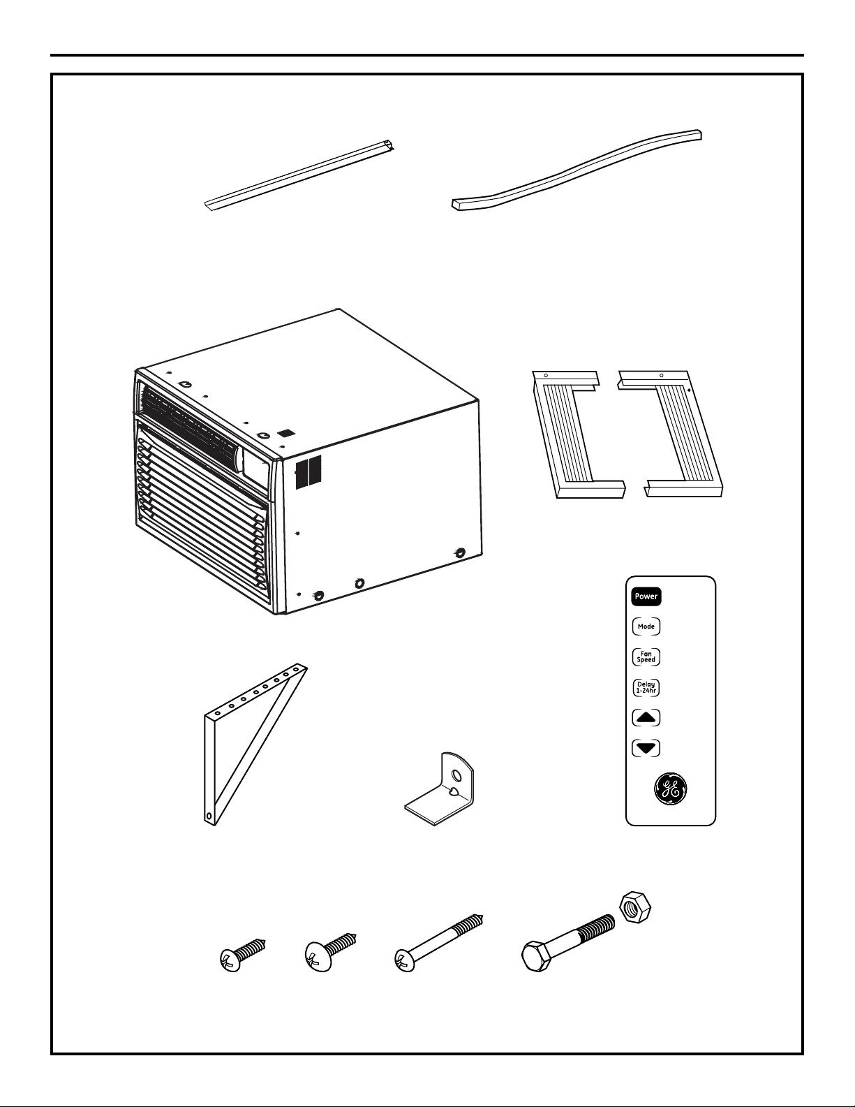
PARTS INCLUDED
(Appearance may vary)
Installation Instructions
Top Mounting Rail
Foam Seal
Left and Right Side
Curtains
Temp / Delay
Installation Bracket (2) Window Lock Bracket Remote Control
ABC D
13/32”
Screws (10)
13/32”
Screws (6)
31/32”
Screws (10)
8
2-1/2” Flat Head Bolt
and Lock Nut (2)
Page 9
Installation Instructions
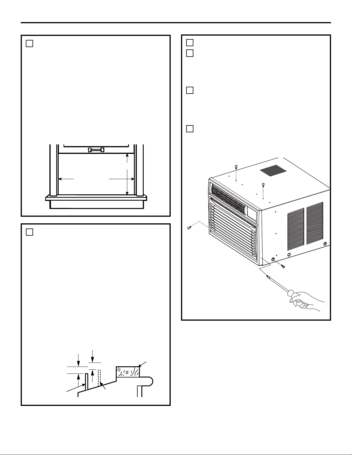
WINDOW REQUIREMENTS
1
These instructions are for a standard
double-hung window. <ou will need to modify
them for other types of windows.
The air conditioner can be installed without the
side curtain panels if needed to fit in a narrow
window. See the window opening dimensions.
All supporting parts must be secured to firm
wood, masonry or metal.
The electrical outlet must be within reach of the
power cord.
Follow the dimensions in the table and
illustration for your model.
20 1/4”
31 1/4” - 40”
(With side curtain panels)
3
PREPARE THE AIR CONDITIONER
Remove two screws on each side of the case.
A
Save the screws for use later. Two screws
on the top of the case are covered by black
adhesive. Remove adhesive and screws.
Insert a flat head screw driver between the
B
front grille and the metal case along the sides.
Gently pry the grille from the case. NOTE: Cover
the flat head screw driver with tape to prevent
scratching the case.
Using the handle on bottom front of the air
C
conditioner, pull air conditioner out of the case.
The air conditioner is very heavy so make sure
that it will be resting on a sturdy surface.
STORM WINDOW REQUIREMENTS
2
A storm window frame will not allow the air
conditioner to tilt toward the outside, and will
keep it from draining properly. To adjust for this,
attach a piece of wood to the sill.
WOOD PIECES
WIDTH: 2s
LENGTH: Long enough to fit inside the window
frame.
THICKNESS: To determine the thickness, place a
piece of wood on the sill to make it 1/2s higher
than the top of the storm window frame or the
vinyl frame.
Attach securely with nails or screws provided
by the installer.
1/2shigher
than storm
window
frame
Storm window
frame
1/2shigher
than vinyl frame
(on some windows)
Sill
Vinyl frame
Wood
9
Page 10
Installation Instructions
4 6
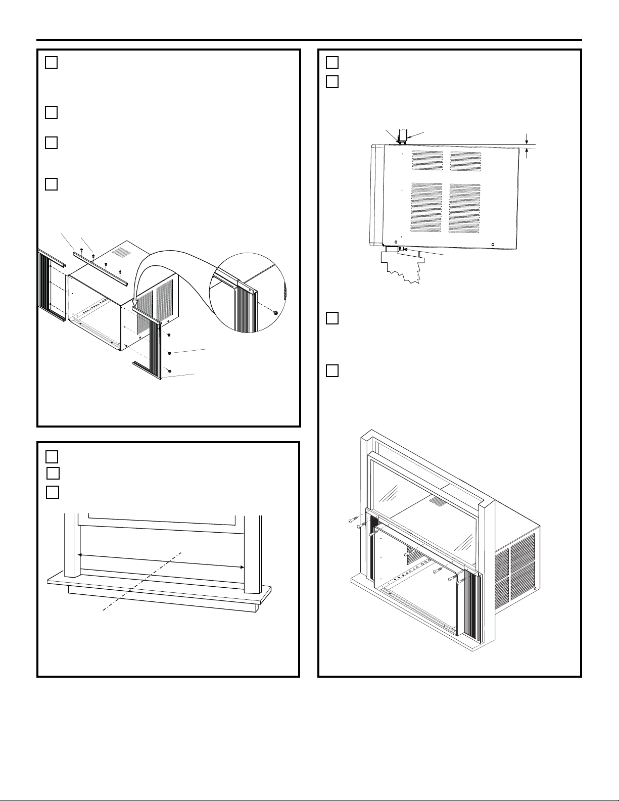
PREPARE THE CASE
NOTE: Attach curtains to the air conditioner
before placing the air conditioner in window.
Install the top mounting rail with four type A
A
screws.
Slide left-hand curtain assembly into left end
B
of top and bottom mounting rail. Repeat for
right-hand curtain assembly.
Fasten curtain retainer strips to the sides of the
C
outer case with three type A screws on each
side.
A
B
C
INSTALL OUTER CASE IN WINDOW
Place outer case in window. Lower sash until it
A
rests behind front flange of top mounting rail.
Bottom mounting rail must rest behind window
sill.
Top rail
SILL
Expand the curtain panels to fill the window.
B
Secure with type C wood screw in top corners.
If needed, use drill and 1/8” bit to drill pilot holes
for the screws.
Window sash
About
Bottom rail
5˚
D
A. Top mounting rail
B. 13/32” screws
PREPARE WINDOW FOR INSTALLATION
5
A
Measure the width of the window opening.
B
Mark the center line on the inside windowsill.
C. 13/32” screws
D. Side curtains
A
B
A. Width of window opening
B. Center line
Use three type C screws to secure the top
C
mounting rail to the window. Drill pilot holes if
necessary.
10
Page 11

Installation Instructions
INSTALL OUTER CASE IN WINDOW
5
Thread nut onto bolt, then thread the bolt into
D
the triangle bracket as shown in the figure
below.
7
COMPLETE INSTALLATION
Insert the foam seal behind the top of the lower
A
window sash and against the glass of the upper
window.
Attach triangle bracket onto bottom of case
E
using three type B screws for each bracket.
Make sure that the bracket is close enough to
the outside wall that the bolt can touch. Adjust
bolt so that it is snug against the outside wall.
A
A. Top of lower window sash
B. Foam seal
Place the window lock bracket as shown. Use
B
a 1/8” drill bit to drill a starter hole through the
hole in the window lock bracket and into the
upper window.
B
CAUTION:
To prevent broken glass or damage to windows,
on vinyl or other similarly constructed windows,
attach the window locking bracket to the
window side jamb with one type B screw.
Attach the window lock bracket to the upper
C
window with a type C screw to secure the
window in place.
NOTE: A block of wood can be placed between
the bolt and the outside wall if the bolt rests
between studs.
Wood
Vinyl
11
Page 12

Installation Instructions
8
RETURN CHASSIS TO THE OUTER CASE
Once the case is securely attached to the
A
window, reinstall the air conditioner. Have two
people lift the air conditioner and slide it into the
case.
Snap the front grill back onto the air conditioner.
B
Use the screws removed at the beginning of the
installation to secure the grille.
9
RETURN CHASSIS TO THE OUTER CASE
Plug into a grounded 3-prong outlet.
C
Press RESET on the power supply cord. See
D
Electrical Requirements.
12
Page 13

Troubleshooting Tips.
Problem Possible Causes What To Do
Air conditioner The air conditioner Make sure the air conditioner plug is pushed
does not start is unplugged. completely into the outlet.
The fuse is blown/circuit Check the house fuse/circuit breaker box and replace
breaker is tripped. the fuse or reset the breaker.
Power failure. The unit will automatically restart in the settings last
used after the power is restored.
There is a protective time delay (approximately
3 minutes) to prevent tripping of the compressor
overload. For this reason, the unit may not start
normal cooling for 3 minutes after it is turned
back on.
The current interrupter Press the RESET button located on the power cord plug.
use of the air conditioner and contact a qualified
service technician.
Air conditioner does Airflow is restricted. Make sure there are no curtains, blinds or furniture
not cool as it should blocking the front of the air conditioner.
The temp control may In the Cool mode, press the Decrease dpad.
The air filter is dirty. Clean the filter at least every 30 days.
See the Care and Cleaning section.
The room may have been hot. When the air conditioner is first turned on, you need
to allow time for the room to cool down.
Cold air is escaping. Check for open furnace registers and cold air returns.
Cooling coils have iced up. See ´Air conditioner freezing up” below.
device is tripped.
not be set correctly.
If the RESET button will not stay engaged, discontinue
Air conditioner Ice blocks the air flow Set the controls at High Fan or High Cool and set the
freezing up and stops the air conditioner thermostat to a higher temperature.
The remote control The battery is inserted Check the position of the battery. They should be
is not working incorrectly. inserted in the opposite (+) and (–) direction.
The battery may be dead. Replace the battery.
Water drips outside Hot, humid weather. This is normal.
Water drips indoors The air conditioner is not For proper water disposal, make sure the air conditioner
tilted to the outside. slants slightly from the case front to the rear.
Water collects in Moisture removed from air This is normal for a short period in areas with little
base pan and drains into base pan. humidity; normal for a longer period in very humid areas.
from cooling the room.
Normal Operating Sounds
<ou may hear a pinging noise caused by
water being picked up and thrown against the
condenser on rainy days or when the humidity
is high. This design feature helps remove
moisture and improve efficiency.
<ou may hear the thermostat click when the
compressor cycles on and off.
Water will collect in the base pan during
high humidity or on rainy days. The water
may overflow and drip from the outdoor side
of the unit.
The fan may run even when the compressor
does not.
13
Page 14

Note
14
Page 15

*($LU&RQGLWLRQHU³2QH<HDU/LPLWHG:DUUDQW\
(For customers in the U.S.A.)
All warranty service provided by our Factory Service Centers,
®
or an authorized Customer Care
technician. To schedule service,
visit us on-line at GEAppliances.com, or call 800.GE.CARES
(800.432.2737). Have serial number and model number available
Staple your receipt here.
Proof of the original purchase
date is needed to obtain service
under the warranty.
when calling for service.
For The Period Of: GE Will Replace:
One Year Any part of the air conditioner which fails due to a defect in materials or workmanship.
From the date of the During this limited one-year warranty, GE will also provide, free of charge, all labor and related
original purchase service to replace the defective part.
What Is Not Covered:
Service trips to your home to teach you how to
use the product.
Improper installation, delivery or maintenance. If you
have an installation problem, or if the air conditioner
is of improper cooling capacity for the intended use,
contact your dealer or installer. You are responsible
for providing adequate electrical connecting facilities.
Failure of the product resulting from modifications to
the product or due to unreasonable use including failure
to provide reasonable and necessary maintenance.
In commercial locations, labor necessary to move the
unit to a location where it is accessible for service
by an individual technician.
Replacement of house fuses or resetting of circuit
breakers.
Failure due to corrosion on models not corrosion-
protected.
Damage to the product caused by improper power
supply voltage, accident, fire, floods or acts of God.
Incidental or consequential damage caused by possible
defects with this air conditioner.
Damage caused after delivery.
(;&/86,212),03/,(':$55$17,(6³<RXUVROHDQGH[FOXVLYHUHPHG\LVSURGXFWUHSDLUDVSURYLGHGLQ
this Limited Warranty. Any implied warranties, including the implied warranties of merchantability or
fitness for a particular purpose, are limited to one year or the shortest period allowed by law.
This warranty is extended to the original purchaser and any succeeding owner for products purchased for
home use within the USA. If the product is located in an area where service by a GE Authorized Servicer is
not available, you may be responsible for a trip charge or you may be required to bring the product to an
Authorized GE Service location for service. In Alaska, the warranty excludes the cost of shipping or service calls
to your home.
Some states do not allow the exclusion or limitation of incidental or consequential damages. This warranty
gives you specific legal rights, and you may also have other rights which vary from state to state. To know
what your legal rights are, consult your local or state consumer affairs office or your state’s Attorney General.
Warrantor: General Electric Company. Louisville, KY 40225
15
Page 16

Consumer Support.
GE Appliances Website
Have a question or need assistance with your appliance? Try the GE Appliances Website 24 hours a day,
any day of the year! For greater convenience and faster service, you can now download Owner’s Manuals,
or even order parts on-line. In Canada: www.GEAppliances.ca
In the U.S.A.: GEAppliances.com
Real Life Design Studio In the U.S.A.: GEAppliances.com
GE supports the Universal Design concept³products, services and environments that can be used by
people of all ages, sizes and capabilities. We recognize the need to design for a wide range of physical
and mental abilities and impairments. For details of GE’s Universal Design applications, including kitchen design
ideas for people with disabilities, check out our Website today. For the hearing impaired, please call 800.TDD.
GEAC (800.833.4322).
In Canada, contact: Manager, Consumer Relations, Mabe Canada Inc.
Suite 310, 1 Factory Lane
Moncton, N.B. E1C 9M3
Parts and Accessories In the U.S.A.: GEAppliances.com
Individuals qualified to service their own appliances can have parts or accessories sent directly to their homes
(VISA, MasterCard and Discover cards are accepted). Order on-line today, 24 hours every day or
by phone at 800.626.2002 during normal business hours.
Instructions contained in this manual cover procedures to be performed by any user. GE does not support
any servicing of the air conditioner. We strongly recommend that you do not attempt to service the air
conditioner yourself.
Customers in Canada should consult the yellow pages for the nearest Mabe service center,
or call 1.800.561.3344.
Contact Us In the U.S.A.: GEAppliances.com
If you are not satisfied with the service you receive from GE, contact us on our Website with all the details
including your phone number, or write to: General Manager, Customer Relations
GE Appliances, Appliance Park
Louisville, K< 40225
In Canada: www.GEAppliances.ca, or write to: Director, Consumer Relations, Mabe Canada Inc.
Suite 310, 1 Factory Lane
Moncton, N.B. E1C 9M3
16
Printed in China
Page 17

GEAppliances.com
Instrucciones de Seguridad ... 2, 3
Instrucciones de Funcionamiento
Controles .............................4
Cuidado y Limpieza
Bobinas Exteriores ....................5
Filtro de Aire ..........................5
Instrucciones de Instalación . 6–10
Consejos para Solucionar
Problemas .........................11
Sonidos Normales de
Para Sala
Funcionamiento .....................11
Soporte al Cliente
Garantía para Clientes en EE.UU ......13
Soporte al Cliente ....................14
Manual del Propietario e
Instrucciones de Instalación
AHH24*
AHM24*
Producto etiquetado *ENERGY STAR
Como socio de ENERGY STAR®,
GE ha confirmado que este
producto cumple las directrices
de ENERGY STAR® relativas al
rendimiento energético.
Escriba los números de modelo y de serie
aquí:
Nº de Modelo _____________________
Nº de Serie _______________________
Estos números se encuentran en una
etiqueta al costado del acondicionador de
aire
®
Acondicionadores de aire
49-7690 12-10 GE
Page 18

INFORMACIÓN IMPORTANTE DE SEGURIDAD.
LEA TODAS LAS INSTRUCCIONES ANTES DE USAR.
¡ADVERTENCIA!
Por su seguridad, se debe seguir la información en este manual para minimizar el riesgo de
incendios, descargas eléctricas o lesiones personales.
PRECAUCIONES DE SEGURIDAD
Use este electrodoméstico solamente para
el propósito determinado según se describe
en el Manual del propietario.
Este acondicionador de aire debe instalarse
correctamente de acuerdo con las
Instrucciones de instalación antes de su uso.
Nunca desenchufe su acondicionador de
aire tirando del cable eléctrico. Siempre
agarre firmemente el enchufe y tire de
él directamente hacia afuera.
Reemplace inmediatamente todos los
cables eléctricos que se hayan pelado o que
se hayan dañado de alguna otra manera.
Un cable de corriente dañado no debe
repararse, sino que debe ser sustituido por
uno nuevo que se adquiera del fabricante.
No use un cable eléctrico que muestre
evidencias de deterioro, o daños de
abrasión en su superficie en alguno de sus
extremos.
Apague la unidad y desenchufe su
acondicionador de aire antes de limpiar.
GE no está no apoya que se le proporcione
ningún servicio al acondicionador de aire.
Vehementemente recomendamos que
usted no intente proporcionar servicio al
acondicionador de aire usted mismo.
Por su seguridad…no almacene ni use
materiales combustibles, gasolina u
otros vapores o líquidos inflamables
en la proximidad de éste o algún otro
electrodoméstico.
Todos los acondicionadores de aire
contiene refrigerantes, los que por Ley
Federal deben ser removidos antes de
desecharlos. Si usted planea deshacerse de
algún producto que contenga refrigerantes,
póngase en contacto con la compañía que
se encarga de recoger su basura para que
le indiquen qué hacer.
Si el receptáculo no coincide con el enchufe,
un electricista calificado debe reemplazar el
receptáculo.
Estos sistemas de acondicionadores de
aire R410A requieren que los contratistas
y técnicos usen herramientas, equipos y
estándares de seguridad aprobados para
su uso con este refrigerante. NO use
equipamiento certificado sólo para
refrigerante R22.
CÓMO CONECTAR LA ELECTRICIDAD
Bajo ninguna circunstancia, corte o remueva la
tercera púa (tierra) del cable eléctrico. En pos
de la seguridad personal, este electrodoméstico
debe siempre conectarse a tierra.
NO use un enchufe adaptador con este
electrodoméstico.
El cable eléctrico de este electrodoméstico está
equipado con un enchufe de tres púas (tierra)
que combina con un tomacorriente estándar
de tres tomas de pared para minimizar la
posibilidad de una descarga eléctrica.
El cable de alimentación incluye un
dispositivo para interrupción de corriente.
Se incluye un botón de prueba y de reinicio
en el dispositivo. El dispositivo debe ponerse
a prueba periódicamente: primero se presiona
el botón de TEST (prueba) y luego RESET
(reinicio) mientras se encuentra enchufado al
tomacorriente. Si el botón TEST no se dispara
o si el botón RESET no queda enganchado,
deje de utilizar el acondicionador de aire y
2
comuníquese con un técnico calificado.
Pida a un técnico que inspeccione el
tomacorriente y el circuito para cerciorarse
de que el tomacorriente está conectado a
tierra de la manera apropiada.
Donde exista un tomacorriente de dos
tomas, es su responsabilidad y obligación
personal hacer que dicho tomacorriente
sea reemplazado por uno de tres tomas
con conexión a tierra.
El acondicionador de aire debería siempre estar
conectado a un tomacorriente individual con su
circuito de voltaje correspondiente.
Esto proporciona el mayor rendimiento y
además evita que los circuitos del resto de
la casa se sobrecarguen, lo cual podría causar
incendios por el sobrecalentamiento del
cableado.
Ver las Instrucciones de instalación, en la
sección Requisitos Eléctricos para los requisitos
específicos de conexión.
Page 19

GEAppliances.com
¡ADVERTENCIA!
USO DE PROLONGADORES
RIESGO DE INCENDIO. Podría ocasionar
lesiones graves o la muerte.
NO use un prolongador con este
Acondicionador de Aire de Ventana.
NO use protectores contra picos de corriente ni
adaptadores para múltiples tomacorrientes con
este Acondicionador de Aire de Ventana.
LEA Y SIGA ESTA INFORMACIÓN DE SEGURIDAD CUIDADOSAMENTE.
GUARDE ESTAS INSTRUCCIONES
3
Page 20

Acerca de los controles en el acondicionador de aire
Las funciones y la apariencia podrán variar.
Las luces junto a las teclas táctiles del panel de control del acondicionador de aire indican las configuraciones
seleccionadas.
NOTA: La pantalla siempre muestra la
temperatura del ambiente, excepto al ajustar
las funciones de Temperatura Configurada o
el Temporizador de Retraso.
Fan
Only
Cool
Energy
Saver
Auto
High
Med
Low
On
Off
°F/°C
Hr
Temp / Delay
Encendido/
apagado de la
Unidad
Modo
Velocidad del
ventilador
Retraso de 1 a
24 hrs.
Incremento
y Reducción
de la
Configuración
de
Temperatura/
Temporizador
de Retraso
Temp / Delay
Controles del Acondicionador de Aire
Control Remoto
Controles
Tecla de Encendido
Enciende y apaga el acondicionador de aire.
Al ser encendido, la pantalla mostrará la
temperatura ambiente.
Pantalla
Muestra la temperatura ambiente o el tiempo
restante en el Temporizador de Retraso.
Muestra la temperatura Configurada mientras
configura la temperatura en los modos Cool
(Fresco) o Energy Saver (Ahorro de Energía). La
luz de Configuración se encenderá mientras se
esté realizando la configuración.
Teclas de Incremento
/Reducción ▼ de
▲
Temperatura y Retraso
Use las mismas para configurar la temperatura
y el tiempo de retraso. La temperatura se puede
configurar en los modos Cool (Fresco), Energy
Saving (Ahorro de Energía) y Auto (Automático).
Tecla de Modo
Use la misma para configurar el acondicionador
de aire en los modos Fan Only (Sólo Ventilador),
Cool (Fresco), Energy Saver (Ahorro de Energía) o
Auto (Automático).
Teclas de Velocidad del Ventilador
Use las mismas para configurar la velocidad
del ventilador en Low (Bajo), Med (Medio), o High
(Alto) en la unidad.
4
Tecla de Retraso
'HOD\215HWUDVR(QFHQGLGR³Cuando el
acondicionador de aire se encuentre apagado,
se podrá configurar para que se encienda
automáticamente en un período de entre 1
y 24 horas en el modo y configuraciones del
ventilador previas.
'HOD\2))5HWUDVRGHO$SDJDGR³Cuando el
acondicionador de aire se encuentre encendido,
se podrá configurar automáticamente para que
se apague en un período de entre 1 y 24 horas.
Cómo configurar:
Presione la tecla Delay 1–24hr (Retraso entre
1 y 24 hrs.) en la unidad o en el control remoto.
Cada vez que presione las teclas Increase
(Incrementar) ▲ / Decrease (Reducir) ▼ de la
unidad o las teclas Increase (Incrementar) +
/ Decrease (Reducir) – del control remoto se
ajustará el temporizador por intervalos de 1
hora.
Para revisar el tiempo restante en el
temporizador de Delay 1–24hr (Retraso entre
1 y 24 hrs), presione la tecla Delay 1–24hr
(Retraso entre 1 y 24 hrs.) de la unidad o
del control remoto. Use las teclas Increase
(Incrementar) ▲ / Decrease (Reducir)▼de la
unidad o las teclas Increase (Incrementar) + /
Decrease (Reducir) – del control remoto para
configurar un tiempo nuevo si así lo desea.
Para cancelar el temporizador, presione la tecla
Delay 1–24hr (Retraso entre 1 y 24 hrs.) hasta
que la luz de la tecla Delay 1–24hr (Retraso
entre 1 y 24 hrs.) se apague.
Page 21

GEAppliances.com
No use en las condiciones externas debajo
el punto de congelación
Control remoto
Para garantizar una operación apropiada, oriente
el control remoto hacia el receptor de señal del
acondicionador de aire.
El receptor de señal tiene un rango máximo de 20
pies.
Modo Cool (Frío)
Use el modo Cool (Frío) a Low (Bajo), Med (Medio),
High (Alto) o Auto Fan Speed (Velocidad de
ventilador automática) para enfriar. Use las teclas
de Temperature (Temperatura) Aumento Ÿ (+)
/ Reducción ź (–) para ajustar a la temperatura
deseada entre 64ºF y 86ºF en incrementos de 1ºF.
Se usa un termostato electrónico para mantener
la temperatura ambiente. El compresor hará
ciclo entre apagado y encendido para mantener
la habitación a la temperatura deseada. Ajuste el
termostato a un número menor y el aire interno
se enfriará más. Si lo ajusta a un número mayor,
la temperatura del aire interno se calentará más.
NOTA: si el acondicionador de aire está apagado
y se enciende mientras está configurado en un
Este acondicionador de aire no es diseñado para
usar en temperaturas externas debajo el punto de
congelación. No use en las condiciones externas
debajo el punto de congelación.
Cerciórese de que no haya nada entre el
acondicionador de aire y el control remoto que
pueda bloquear la señal.
Cerciórese de que las baterías sean frescas y se
instalen correctamente según se indica en el
control remoto.
ajuste Cool (Frío) o si se cambia de un ajuste de
ventilador a uno de Cool (Frío), puede que pasen
aproximadamente unos 3 minutos hasta que el
compresor arranque y comience el enfriamiento.
Descripciones de enfriamiento
3DUDHQIULDPLHQWRQRUPDO³Seleccione el modo
Cool (Frío) y ventilador High (Alto) o Med (Medio)
con una temperatura de ajuste media.
3DUDHQIULDPLHQWRPi[LPR³Seleccione el modo
Cool (Frío) y ventilador High (Alto) con una
temperatura de ajuste menor.
Para enfriamiento silencioso y enfriamiento
QRFWXUQR³Seleccione el modo Cool (Frío) y ventilador
Low (Bajo) con una temperatura de ajuste media.
Energy Saver Mode (Modo de ahorro de energía)
Controla el ventilador.
ON (ENCENDIDO)—El ventilador hará un ciclo
de encendido y apagado con el compresor. Este
resulta en variaciones mayores en la temperatura
de la habitación y en la humedad. Normalmente
usado cuando la habitación no está ocupada.
NOTA: puede que el ventilador siga funcionando
durante un corto tiempo después de desactivarse el
ciclo del compresor.
OFF (APAGADO)—El ventilador funciona todo el
tiempo, mientras que el compresor pasa por los
ciclos de encendido y apagado.
Modo de Sólo Ventilador
Use Fan Only Mode (Modo de Sólo Ventilador) en
la velocidad de ventilador Low (Baja), Med (Media)
o High (Alta), a fin de brindar una circulación de
aire y filtrado sin enfriamiento. Debido a que las
configuraciones de sólo ventilador no brindan
enfriamiento, no se podrá ingresar una temperatura
configurada. La temperatura del ambiente aparecerá
en la pantalla.
Modo Automático
Configure en Auto (Automática) para que la velocidad
del ventilador se configure de forma automática en la
velocidad necesaria para brindar ajustes de confort
óptimos con la temperatura configurada.
Si se necesita más frío en la habitación, la velocidad
del ventilador se incrementará de forma automática.
Si se necesita más frío en la habitación, la velocidad
del ventilador se reducirá de forma automática.
5
Page 22

Acerca de los controles en el acondicionador de aire.
Información adicional importante.
Dirección del Aire
Use la palanca para ajustar la dirección del aire hacia
la izquierda, derecha, arriba y abajo.
Cuidado y limpieza del acondicionador de aire.
Rejilla y caja
Apague el acondicionador de aire y retire el enchufe
del tomacorriente de la pared antes
de limpiar.
Filtro de aire
El filtro de aire detrás de la rejilla frontal debe
inspeccionarse y limpiarse por lo menos cada
30 días o más a menudo si fuese necesario.
Para retirarlo:
Abra la rejilla de entrada empujando hacia abajo
las lengüetas en las esquinas superiores de la rejilla
de entrada, hasta que la rejilla se encuentre en una
posición de 45º. Retire el filtro.
Limpie el filtro con agua tibia y jabón. Enjuáguelo y
permita que se seque antes de colocarlo otra vez en
su lugar. No lave el filtro en un lavavajillas.
Para limpiar, use agua y un detergente suave.
No use cloro o materiales abrasivos.
PRECAUCIÓN: NO OPERE el
acondicionador de aire sin el filtro debido a que la
suciedad y las pelusas lo obstruirán y reducirán su
rendimiento.
Bobinas para exteriores
Se deben inspeccionar con frecuencia las bobinas
en el lado exterior del acondicionador de aire. Si
las mismas están obstruidas con suciedad u hollín,
podrían limpiarse profesionalmente.
Cómo insertar las pilas en el control remoto
Retire la cubierta de la pila deslizándola
1
de acuerdo con la dirección de la flecha.
Inserte pilas nuevas cerciorándose de que los
2
polos positivos (+) y negativos (–) están
orientados correctamente.
Coloque la cubierta otra vez deslizándola
3
en su lugar.
6
NOTAS:
Use 2 pilas alcalinas “AAA” de 1,5 voltios.
No use pilas recargables.
Retire las pilas del control remoto si no va
a usar el sistema por un período prolongado.
Page 23

Instrucciones
Acondicionador
de instalación
¿Preguntas? Llame 800.GE.CARES (800.432.2737) o visite nuestra página en la red en: GEAppliances.com
ANTES DE INICIAR
Lea estas instrucciones completa y
cuidadosamente.
IMPORTANTE ³ Guarde estas
instrucciones para uso del inspector local.
IMPORTANTE ³ Observe todos los
códigos y órdenes de ley.
Nota al instalador – Asegúrese de dejar estas
instrucciones con el consumidor.
Nota al consumidor – Conserve estas
instrucciones para referencia futura.
Nivel de destreza – La instalación de este
aparato requiere de destrezas mecánicas
básicas.
7LHPSRGHHMHFXFLyQ –
Recomendamos dos personas para
la instalación de este producto.
La instalación apropiada es la responsabilidad
del instalador.
La falla del producto debido a una instalación
inadecuada no está cubierta
por la garantía.
Cuando instale este acondicionador
de aire, DEBE usar todas las piezas
suministradas y usar procedimientos adecuados
de instalación.
Aprox. 1 hora
PRECAUCIÓN:
Bajo ninguna circunstancia corte o remueva la
tercera púa (conexión a tierra) del cable eléctrico.
No cambie el enchufe en el cable eléctrico
de este acondicionador de aire.
Los cables caseros de aluminio podrían presentar
problemas especiales. Consulte
a un técnico electricista calificado.
El enchufe de tres púas con conexión a tierra
minimiza la posibilidad de descargas eléctricas. Si
el tomacorriente de la pared que usted planea usar
solamente tiene 2 tomas, es su responsabilidad hacer
que un técnico lo reemplace por uno de tres tomas
con conexión a tierra.
El cable de alimentación incluye un dispositivo para
interrupción de corriente. Se incluye un botón de prueba
y de reinicio en el dispositivo. El dispositivo debe ponerse
a prueba periódicamente: primero se presiona el botón
de TEST (prueba) y luego RESET (reinicio) mientras se
encuentra enchufado al tomacorriente. Si el botón TEST
no se dispara o si el botón RESET no queda enganchado,
deje de utilizar el acondicionador de aire y comuníquese
con un técnico calificado.
REQUISITOS ELÉCTRICOS
Algunos modelos requieren tomacorrientes de
115/120 voltios de corriente alterna y 60 Hz
conectados a tierra, protegidos con un fusible
de dilatación de tiempo de 15 amperios
o un cortacircuitos.
Algunos modelos requieren 230/208 voltios,
de corriente alterna, protegidos por un fusible
de dilatación de tiempo
o un cortacircuitos. Estos modelos deberían
instalarse en un ramal exclusivo del circuito
para un rendimiento más notable y para
prevenir sobrecargas en los circuitos de
cableados de su casa o apartamento,
lo cual podría representar un riesgo
de incendio por el sobrecalentamiento de los
alambres.
de aire
7
Page 24

Instrucciones de instalación
HERRAMIENTAS QUE NECESITARÁ
Un destornillador de estrella
PARTES INCLUIDAS
(Apariencia puede variar)
Llave francesa
Taladro y broca de 1/8”
Tijeras o cuchilla
Riel de montaje superior Sellador de Gomaespuma
Una regla o cinta métrica
Lápiz
Nivel
Soporte de Instalación (2)
A. Tornillos de
13/32” (12)
Soporte de Bloqueo para Ventana
B. Tornillos de
13/32” (6)
C. Tornillos de
31/32” (8)
Cortinas Izquierda y Derecha
Control Remoto
Temp / Delay
D. Tornillo de Cabeza Plana
de 2-1/2” y Tuerca de
Bloqueo (2)
8
Page 25

Instrucciones de instalación
REQUISITOS PARA LA VENTANA
1
Estas instrucciones son para una
ventana estándar de dos pliegues.
Usted necesitará modificar el proceso para otros
tipos de ventanas.
Todas las partes de apoyo deben quedar totalmente
aseguradas a algún metal, mampostería o a la
madera.
El tomacorriente eléctrico debe estar al alcance del cable
eléctrico del acondicionador de aire.
Siga las dimensiones de la tabla y la ilustración según su
modelo.
18 15/32”
3
PREPARE EL ACONDICIONADOR DE
AIRE
Retire los tres tornillos que se encuentran a
A
cada lado de la caja. Guarde los mismos para
su uso posterior. En la parte superior de la caja
se encuentran dos tornillos cubiertos por cinta
adhesiva negra. Retire la cinta adhesiva y los
tornillos.
Inserte un tornillo de cabeza plana entre la
B
parrilla frontal y la caja de metal sobre los
costados. Suavemente levante la parrilla de la
caja. NOTA: Cubra el destornillador de cabeza
plana con cinta, a fin de evitar rayones sobre la
caja.
26” - 41”
(con paneles de acordeón)
REQUISITOS DE UNA VENTANA
2
DE TORMENTAS
Un marco de ventana de tormentas no permitirá que
el acondicionador de aire se incline hacia el exterior y
evitará que drene apropiadamente. Para solucionar este
problema, adhiera un pedazo de madera a el umbral.
PEDAZOS DE MADERA
ANCHO: 2s
LONGITUD: Lo suficientemente largo como para
ajustar en el interior del marco de la ventana.
GRUESO: Para determinar el grueso, coloque un pedazo
de madera en el umbral para hacerla 1/2s más alta que
la parte superior del marco de la ventana de tormentas
o del marco vinilo.
Péguelo firmemente con clavos o con tornillos
proporcionados por el instalador.
Utilizando la manija en la parte frontal
C
inferior del acondicionador de aire, empuje el
acondicionador de aire hacia afuera de la caja.
El acondicionador de aire es muy pesado; por
lo tanto, asegúrese de que sea apoyado sobre
una superficie sólida.
1/2smás alto
que el marco
de ventana de
tormentas
Marco de
ventana de
tormentas
1/2smas alto que el marco
vinilo (en algunas ventanas)
Madera
Umbral
Marco vinilo
9
Page 26

Instrucciones de instalación
PREPARE LA CAJA
4
NOTA: Coloque las cortinas en el acondicionador
de aire antes de colocar el acondicionador de aire
en la ventana.
Instale el riel de montaje superior con cuatro
A
tornillos tipo A.
Deslice la junta de la cortina del lado izquierdo
B
en el extremo izquierdo de los rieles de montaje
superior e inferior.
Coloque las tiras de retención de la cortina sobre
C
los costados de la caja externa con cuatro tornillos
tipo A en cada lado.
A
B
INSTALE LA CAJA EXTERIOR EN LA
5
VENTANA
Coloque la caja exterior en la ventana. Baje
A
el marco hasta que se apoye detrás de la
pestaña frontal del riel de montaje superior. El
riel de montaje inferior se deberá apoyar detrás
del alféizar de la ventana.
Top rail
Riel superior
SILL
Marco de la ventana
Window sash
Bottom rail
Riel inferior
ALFÉIZAR
About
Aproximad-
5˚
amente 5º
C
D
A. Riel de montaje superio
A. Top mounting rail
B. Tornillos de 13/32
B. 13/32” screws
C. Tornillos de 13/32
D. Cortinas deslizables
PREPARE LA VENTANA PARA SU
5
C. 13/32” screws
D. Side curtains
INSTALACIÓN
Mida el ancho de apertura de la ventana.
A
Marque la línea central en la parte inferior del
B
alféizar de la ventana.
A
Expanda los paneles de la cortina hasta cubrir la
B
ventana. Asegure estos con un tornillo de madera
tipo C en los ángulos superior e inferior. Si es
necesario, use un taladro y una broca de 1/8”
para taladrar agujeros piloto para los tornillos.
Use tornillos tipo C para asegurar el riel de
C
montaje superior a la ventana. Taladre agujeros
piloto si es necesario.
B
A. Ancho de apertura de la ventana
A. Width of window opening
B. Línea central
B. Center line
10
Page 27

Instrucciones de instalación
INSTALE LA CAJA EXTERNA PARA
5
VENTANA
Enrosque la tuerca en el tornillo; luego enrosque
D
el tornillo en el soporte triangular, como se
muestra en la figura más abajo.
Adhiera el soporte triangular a la parte inferior
E
de la caja, usando tres tornillos tipo B para
cada soporte. Asegúrese de que el soporte se
encuentre lo suficientemente cerca de la pared
exterior de modo que tenga contacto con el
tornillo. Ajuste el tornillo de manera que se
ajuste contra la pared exterior.
6
INSTALACIÓN COMPLETA
Inserte el sello de gomaespuma detrás de la
A
parte superior del marco de la ventana y contra
el vidrio de la ventana superior.
A
A. Parte superior del marco inferior de la ventana
B. Sellador de gomaespuma
Coloque el soporte de bloqueo de la ventana
B
como se muestra. Use una broca de 1/8” para
taladrar un agujero inicial a través del agujero
del soporte de bloqueo de la ventana y en la
ventana superior.
B
PRECAUCIÓN:
Para evitar la rotura de vidrios o daños sobre las
ventanas, en ventanas de vinilo u otras
ventanas construidas de forma similar, adhiera
el soporte de bloqueo de la ventana a la jamba
lateral de la ventana con un tornillo tipo B.
NOTA: Se puede colocar un bloque de madera
entre el tornillo y la pared exterior, si el tornillo se
encuentra entre montajes.
Adhiera el soporte de bloqueo de la ventana a
C
la ventana superior con un tornillo tipo C, a fin
de asegurar la ventana en su posición.
Madera
Vinilol
11
Page 28

Instrucciones de instalación
7
R
EGRESE EL CHASIS A LA CAJA EXTERNA
Una vez que la caja se haya asegurado a la
A
ventana, vuelva a instalar el acondicionador de
aire. Asegúrese de que dos personas levanten
el acondicionador de aire y que lo deslicen en la
caja.
Presione la parrilla frontal nuevamente sobre el
B
acondicionador de aire. Use los tornillos retirados
al comenzar la instalación, para asegurar la
parrilla.
7
REGRESE EL CHASIS A LA CAJA EXTERNA
ADVERTENCIA
Riesgo de Descarga Eléctrica
No retire el cable a tierra.
No use un adaptador.
No use un prolongador.
Si no se siguen estas instrucciones, se podrá pro-
ducir la muerte, incendio o descargas eléctricas.
Enchufe en un tomacorriente de 3 patas con
C
conexión a tierra.
Presione RESET (Reiniciar) en el cable de
D
suministro de corriente. Consulte Requisitos
Eléctricos.
12
Page 29

Solucionar problemas.
Problema Causas posibles Qué hacer
El acondicionador de aire El acondicionador de aire Cerciórese de que el acondicionador de aire está
no enciende está desconectado. enchufado totalmente en el tomacorriente.
El fusible se disparó / Inspeccione los fusibles / caja de interruptores de la casa
el cortacircuitos se disparó. y reemplace cualquier fusible o reajuste el interruptor.
Interrupción en el La unidad se reiniciará automáticamente con la configuración
suministro eléctrico. utilizada por última vez luego de reestablecer la electricidad.
Existe un retraso de tiempo por protección (de aproximadamente
3 minutos) para evitar la desconexión por sobrecarga del compresor.
Por esta razón, es posible que la unidad no comience a enfriar de
forma normal hasta transcurridos 3 minutos desde que volvió a
encenderse.
El dispositivo de interrupción Presione el botón RESET ubicado en el cable de alimentación.
el acondicionador de aire y comuníquese con un técnico calificado.
El acondicionador de aire El flujo de aire está restringido. Cerciórese de que no existe ninguna cortina, persiana o
no enfría como debería mueble bloqueando el frente del acondicionador de aire.
El filtro de aire está sucio. Limpie el filtro cada 30 días por lo menos. Ver la sección
de
La habitación podría haber Cuando el acondicionador de aire se enciende, usted
estado caliente. necesita darle tiempo para que enfrié la habitación.
El aire frío se está escapando. Cerciórese de que los registros de la calefacción no están
abiertos y se encuentran retornando el aire frío.
Las bobinas de enfriamiento Ver “El acondicionador de aire se está congelando” más adelante.
se congelaron.
El acondicionador de aire El hielo bloquea el flujo Colo que los controles en High Fan (Ventilador Alto) ó High Cool (Frío
se está congelando de aire hacia el acondicionador Alto) y ajuste el termostato a una temperature más alta.
de aire evitando que se enfríe
la habitación.
Hay agua goteando afuera Tiempo húmedo y caliente. Esto es normal.
Hay agua goteando en el El acondicionador de aire Para drenar el agua apropiadamente, cercíorese de que
interior de la habitación no está inclinado hacia afuera. el acondicionador de aire está inclinado ligeramente
desde el frente hacia atrás.
Se acumula agua en La humedad removida del aire Esto es normal por un corto período en áreas con poca
la bandeja y se drena hasta la bandeja. humedad; normal por un período de tiempo más postergado
en áreas más húmedas.
de corriente se ha activado.
Si el botón RESET no se mantiene en su lugar, no utilice más
Cuidado y limpieza
.
Sonidos de operación normales
Quizás escuche un sonido metálico causado por
el agua tomada y tirada contra el condensador
en los días lluviosos o cuando la humedad
es alta. Esta característica de diseño ayuda a
remover
la humedad y mejora la eficiencia.
Quizás escuche que el termostato hace clic
cuando el compresor hace ciclo entre encendido
y apagado.
13
El agua se acumula en la bandeja durante días
lluviosos o con mucha humedad. El agua podría
derramarse y gotear desde el lado externo de
la unidad.
El ventilador podría funcionar aun si el compresor
no lo hace.
Page 30

Notas.
14
Page 31

Notas.
GEAppliances.com
15
Page 32

Notas.
16
Page 33

Notas.
GEAppliances.com
17
Page 34

Garantía de su acondicionador de aire³JDUDQWtDOLPLWDGDGHXQDxR.
Todos los servicios de garantía los proporcionan nuestros
Centros de Reparación de Fábrica o nuestros técnicos Customer
®
autorizados. Para concertar una cita de reparación,
Care
en línea, 24 horas al día, visítenos al ge.com, o llame al 800.
GE.CARES (800.432.2737). Cuando llame para solicitar servicio,
Grape aquí su recibo.
Se requiere facilitar prueba
de la fecha de compra original
para obtener un servicio
bajo la garantía.
por favor tenga a mano el número de serie y el número de
modelo.
Por el período de: GE reemplazará:
8QDxR &XDOTXLHUSDUWHdel acondicionador de aire que falle debido a defectos en los materiales o en
A partir de la fecha la fabricación. Durante esta garantía limitada de un año, GE también proporcionará, sin costo
de la compra original alguno, toda la mano de obra y el servicio relacionado³para reemplazar partes defectuosas.
Lo que no está cubierto:
Viajes de servicio a su casa para mostrarle cómo
funciona el equipo.
Instalación o entrega inapropiada, o mantenimiento
impropio. Si usted tiene un problema durante la
instalación, o si su acondicionador de aire no tiene la
capacidad de enfriamiento que usted necesita, póngase
en contacto con nuestro distribuidor o instalador.
Usted es responsable de proporcionar las facilidades
de conexión eléctrica necesarias.
Fallo del producto resultante de modificaciones al
producto o debido a uso irrazonable incluyendo no
proporcionar mantenimiento razonable y necesario.
Reemplazo de fusibles de la casa o reajuste del sistema
de circuitos.
Fallos debido a la corrosión en modelos que no están
protegidos contra la corrosión.
Daño al producto causado por voltaje inapropiado hacia
el equipo, accidentes, incendios, inundaciones o actos
de la naturaleza de fuerza mayor.
Daños incidentales o consecuenciales causados por
defectos posibles con este acondicionador de aire.
Daños después de la entrega.
En locales comerciales, la mano de obra necesaria para
retirar la unidad hacia un lugar para revisión por parte
de un técnico individual.
(;&/86,Ï1'(*$5$17Ë$6,03/Ë&,7$6³6X~QLFR\H[FOXVLYRGHUHFKRHVODUHSDUDFLyQGHOSURGXFWR
tal y como se indica en esta Garantía limitada. Cualquier garantía implícita, incluyendo las garantías
LPSOtFLWDVGHFRPHUFLDELOLGDGRDGHFXDFLyQSDUDXQILQGHWHUPLQDGRHVWiQOLPLWDGDVDXQDxRRHO
período de tiempo más breve permitido por la ley.
Esta garantía se extiende al comprador original y cualquier comprador posterior de productos comprados para uso
residencial dentro de Estados Unidos. Si el producto está situado en un área que no dispone de servicio por parte
de un proveedor de servicio autorizado de GE, podría tener que hacerse cargo de los costes de envío o bien
podría solicitársele que lleve el producto a una centro de servicio de GE autorizado para realizar la reparación.
En Alaska, la garantía excluye el costo de envío o las visitas de servicio a su casa.
Algunos estados no permiten la exclusión o las limitaciones de daños incidentales o consecuenciales. Esta garantía
da derechos legales específicos, y usted podría tener otros derechos que variarán de estado a estado. Para saber
cuáles son sus derechos legales, consulte a la oficina de asuntos del consumidor local o la oficina del Attorney General
en su localidad.
Garante: General Electric Company. Louisville, KY 40225
1
Page 35

Apoyo al consumidor.
Página Web de GE Appliances
¿Tiene alguna pregunta sobre su electrodoméstico? ¡Pruebe la página Web de GE Appliances 24 horas al día,
cualquier día del año! Para mayor conveniencia y servicio más rápido, ya puede descargar los Manuales de los
Propietarios, pedir piezas o incluso hacer una cita en línea para que vengan a realizar una reparación.
Real Life Design Studio (Estudio de diseño para la vida real)
GE apoya el concepto de Diseño Universal³productos, servicios y ambientes que pueden usar gente de todas
las edades, tamaños y capacidades. Reconocemos la necesidad de diseñar para una gran gama de habilidades
y dificultades físicas y mentales. Para más detalles cobre las aplicaciones de GE Diseño Universal, incluyendo
ideas de diseño para la cocina para personas con discapacidades, mire nuestra página Web hoy mismo. Para
personas con dificultades auditivas, favor de llamar al 800.TDD.GEAC (800.833.4322).
Piezas y accesorios
Aquellos individuos con la calificación necesaria para reparar sus propios electrodomésticos pueden
pedir que se les manden las piezas o accesorios directamente a sus hogares (aceptamos las tarjetas
VISA, MasterCard y Discover). Haga su pedido en línea hoy, 24 horas cada día o llamar por teléfono
al 800.626.2002 durante horas normales de oficina.
Las instrucciones descritas en este manual cubren los procedimientos a seguir por cualquier usuario.
GE no está no apoya que se le proporcione ningún servicio al acondicionador de aire. Vehementemente
recomendamos que usted no intente proporcionar servicio al acondicionador de aire usted mismo.
GEAppliances.com
GEAppliances.com
GEAppliances.com
Póngase en contacto con nosotros
Si no está satisfecho con el servicio que recibe de GE, póngase en contacto con nosotros en nuestra página
Web indicando todos los detalles así como su número de teléfono o escríbanos a:
General Manager, Customer Relations
GE Appliances, Appliance Park
Louisville, KY 40225
GEAppliances.com
2
Page 36

Consumer Support.
GE Appliances Website
Have a question or need assistance with your appliance? Try the GE Appliances Website 24 hours a day,
any day of the year! For greater convenience and faster service, you can now download Owner’s Manuals,
or even order parts on-line. In Canada: www.GEAppliances.ca
In the U.S.A.: GEAppliances.com
Real Life Design Studio In the U.S.A.: GEAppliances.com
GE supports the Universal Design concept³products, services and environments that can be used by
people of all ages, sizes and capabilities. We recognize the need to design for a wide range of physical
and mental abilities and impairments. For details of GE’s Universal Design applications, including kitchen design
ideas for people with disabilities, check out our Website today. For the hearing impaired, please call 800.TDD.
GEAC (800.833.4322).
In Canada, contact: Manager, Consumer Relations, Mabe Canada Inc.
Suite 310, 1 Factory Lane
Moncton, N.B. E1C 9M3
Parts and Accessories In the U.S.A.: GEAppliances.com
Individuals qualified to service their own appliances can have parts or accessories sent directly to their homes
(VISA, MasterCard and Discover cards are accepted). Order on-line today, 24 hours every day or
by phone at 800.626.2002 during normal business hours.
Instructions contained in this manual cover procedures to be performed by any user. GE does not support any
servicing of the air conditioner. We strongly recommend that you do not attempt to service the air conditioner
yourself.
Customers in Canada should consult the yellow pages for the nearest Mabe service center,
or call 1.800.561.3344.
Contact Us In the U.S.A.: GEAppliances.com
If you are not satisfied with the service you receive from GE, contact us on our Website with all the details
including your phone number, or write to: General Manager, Customer Relations
GE Appliances, Appliance Park
Louisville, KY 40225
In Canada: www.GEAppliances.ca, or write to: Director, Consumer Relations, Mabe Canada Inc.
Suite 310, 1 Factory Lane
Moncton, N.B. E1C 9M3
Printed in China
 Loading...