

GE AGW12AKG1, AGH12AKG1, AGW10AKM1 Owner’s Manual
©
Safety Instructions ........ 2, 3
Operating Instructions ..... 4, 5
Care and Cleaning
Air Filter .................. 6
Grille and Case ............. 6
Outdoor (]oils .............. 6
Installation Instructions
Preparing to Install the
Air Conditioner ............. 7
Through-the-Wall
Installation--Optional ....... 13
Window Installation ....... 8-12
Troubleshooting Tips ...... 14
Normal Operating Sounds . . .15
ge.com
A GWI 0
A(;HI2
AGWI2
Consumer Support
Consumer Support ......... 18
Warranty ................. 17
Writethemodelandserial numbershere:
Model #
Serial #
Find these numbers on a label on the
side of the air condifioneL
49-7565 11-06JR
iMPORTANTSAFETYiNFORMATiON.
READALLiNSTRUCTiONSBEFOREUSING.
A
For your safety, the information in this manual must be followed to minimize the risk of fire, electric shock
or personal injury.
m
SAFETYPRECAUTIONS
iiiiiiiiiiiii!
Use this appliance only for its intended
purpose as described in this Owner's
Manual.
This air conditioner must be properly
installed in accordance xdth the Installation
Instructions before it is used.
Never unplug your air conditioner by
pulling on the power cord. Always grip
plug firmly and pull straight out from the
receptacle.
Replace immediately all electric ser\,ice
cords that have become fiayed or otherwise
damaged. A damaged power supply cord
must be replaced with a new power supply
cord obtained fiom the manufacturer and
not repaired. Do not use a cord that shows
cracks or abrasion damage along its length
or at either the plug or connector end.
If the receptacle does not match the plug,
the receptacle must be changed out by a
qualified electrician.
Turn the unit OFFmld unplug your air
conditioner before making any repairs
or cleaning.
GE does not support rely ser\,icing of the
air condidone_: We strongly recommend
that you do not attempt to serx@e the
air conditioner yoursel£
For your safety...do not store or use
combustible mamrials, gasoline or other
flammable vapors or liquids in the x,icinity
of this or any other appliance.
All air conditioners contain refiigerants,
which under federal law must be removed
prior m product disposal. If you are getting
rid of an old product with refrigerants, check
with the company handling disposal about
what to do.
HOWTOCONNECTELECTRICITY
Do not, under any circumstances, cut or remove
the third (ground) prong from the power cord. For
personal safety, this appliance must be properly
grounded.
DONOT use an adapter plug with thisappliance.
The power cord of this appliance is equipped
with a 3-prong (grounding) plug which mates
with a standard 3-prong (grounding) wall
outlet to minimize the possibility of electric
shock hazard from this appliance.
Power cord includes a current intermpmr
dex,ice. A test and reset button is prox,ided on
the plug case. The dex,ice should be tested on a
periodic basis by first pressing the rESrbutton
and then the RESErbuuon._f the rESrbutto.
does not trip or if the RESErbutton will not
stay engaged, discontinue use of the air
conditioner and contact a qualified
ser\,ice technician.
Have the wall outlet and circuit checked by a
qualified electrician to make sure the outlet is
properly _ounded.
Where a 2-prong wall outlet is encounmred,
it is your personal responsibility and obligation
to have it replaced with a properly grounded
3-prong wall outlet.
The air conditioner should always be
plugged into its own indix,idual electrical
outlet which has a voltage rating that matches
the rating plate.
This prox,ides the best performance and also
prevents overloading house xdring circuits
which could cause a fire hazard from
overheated xdres.
See the Installation Instructions, Electrical
Requirements section fin specific electrical
connection requirements.
2
WARNING!
USEOFEXTENSIONCORDS
Because of potential safety hazards under certain
conditions, we strongly recommend against the
use of an extension cord.
However, if you must use an extension cord,
it is absolumly necessa U that it be a UL-listed,
14 gauge, 3:wire grounding type appliance
extension cord ha\,ing a _ounding type plug
and outlet and that the electrical rating of the
cord be 15 amperes (minimum) and 195 vohs.
ge.com
READANDFOLLOWTHISSAFETYINFORMATIONCAREFULLY.
SAVETHESEINSTRUCTIONS
3
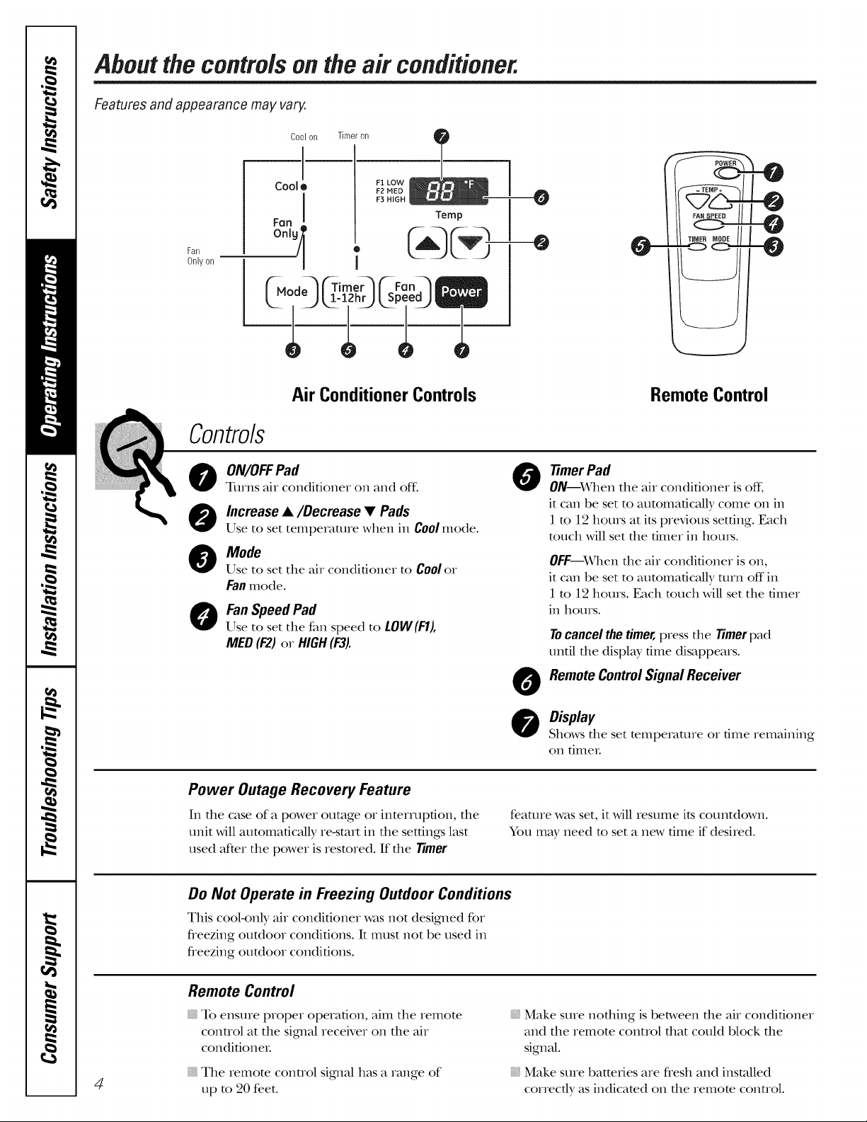
About the controls on the air conditioner.
Features and appearance may vary.
Coolon Timeron
Co01 • F1 LOW
I a.%
Fan ! Temp
Fan
Only on
M Timer Fan
--0
Air Conditioner Controls
Controls
ON/OFFPad
0
Turns air conditioner on and off.
Increase •/Decrease • Pads
@
Use to set temperature when in Coolmode.
Mode
@
Use to set tile air conditioner to Coolor
Fanmode.
Fan Speed Pad
0
Use to set tile fan speed to LOW(F1),
MED(F2) or HIGH(F3).
Power Outage Recovery Feature
In tile case of a power outage or interruption, tile
unit will atKomafically re-start in tile settings last
used after tile power is restored. If tile Timer
Remote Control
fimer Pad
0
ON--When tile air conditioner is off.
it can be set to attmmafically come on in
1 m 12 hours at its previous setting. Each
touch will set tile timer in houls.
OFF_\_31en tile air conditioner is on,
it can be set to attmmatically mrn off in
1 m 12 hours. Each much will set tile timer
in hours.
Tocancelthetimer,press tile Timerpad
until tile display time disappears.
Remote ControlSignal Receiver
O
O Display
Shows tile set temperature or time remaining
on timeL
feature was set, it will resmne its countdown.
You may need to set a new time if desired.
Do Not Operate in Freezing Outdoor Conditions
This cool<rely air conditioner was not designed for
freezing outdoor conditions. It must not be used in
fieezing outdoor conditions.
Remote Control
To ensure proper operation, aim tile remote
control at tile sigmal receiver on tile air
condifioneL
4
Tile remote control sigmal has a range of
tap to 20 feet.
Make sure nofldng is between file air conditioner
and tile remote conuol that could block the
signal.
Make sure batteries are flesh and installed
correctly as indicamd on the remora conuol.
Lights next to the touch pads on the air conditioner
control panel indicate the selected settings.
CoolMode
Use the Coolmode with HIGH(F3), MED (F2) or
LOW(F1) fan for cooling. Use the INCREASER=/
DECREASE • pads to set the desired tempemune
between 60°F and 86°F in 1°F increments.
An electronic fllemlostat is used to maintain file
room temperature. The compressor will cycle on and
off to keep file room at file set level of comfort. Set
file themlostat at a lower number and file indoor air
will become cooleL Set file flleI_nostat at a higher
number and file indoor air will become wamleL
NOTE:If theair conditioneris off andis thenturnedon
whilesettoa Coolsettingorif turnedfrom afansetting
to a Coolsetting,# will takeappreximately3minutes for
the compressortostartand coolingto begin.
Fan Speed Mode
Use the fan at HIGH(F3),MED(F2)or LOW(F1)to
provide air circulation and filtering without cooling.
Since fan only settings do not provide cooling,
a mmperamre setting will not be displayed.
_e.com
CoolingDescriptions
ForNormal Cooling--Select file Cool mode and
HIGH(F3)or MED(F2)fan wifll a middle set
temperature.
ForMaximumCooling--Select file Coolmode
and HIGH(F3)fan with a lower set temperature.
For Quieter & Nighttime Cooling--Select file
Cool mode and LOW (F1)fan with a middle set
temperature.
NOTE:If youswitch from a Coolsettingto OFFor to
a fan setting,wait at least 3 minutesbeforeswitching
back to a Coolsetting.
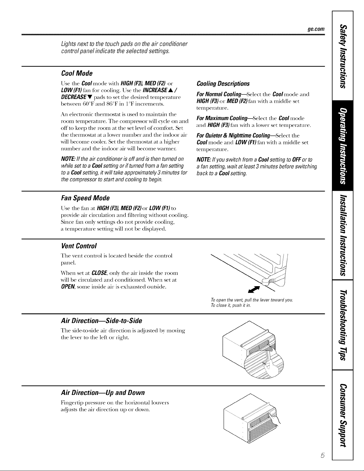
Vent Control
The vent control is located beside the control
panel.
X_qmnset at CLOSE,only the air inside the room
will be circulamd and conditioned. When set at
OPEN,some inside air is exhausted outside.
Air Direction--Side-to-Side
The side-to-side air direction is adjusted by moving
the lever to the left or right.
Air Direction--Up and Down
Fingertip pressure on the horizontal louvers
adjusts the air direction up or down.
Toopen the vent, pull the lever toward you.
Toclose it, push it in.
5
Careand cleaningof theair conditioner.
Grille and Case
Turn the air conditioner off and remove the plug To clean, use water and a mild detergent° Do not
flom the wall outlet before cleaning, use bleach or M)msives.
Outdoor Coils
The coils on file outdoor side of file air conditioner
should be checked regularly: If flley are clogged
Mth dirt or soot, they may be professionMly
cleaned.
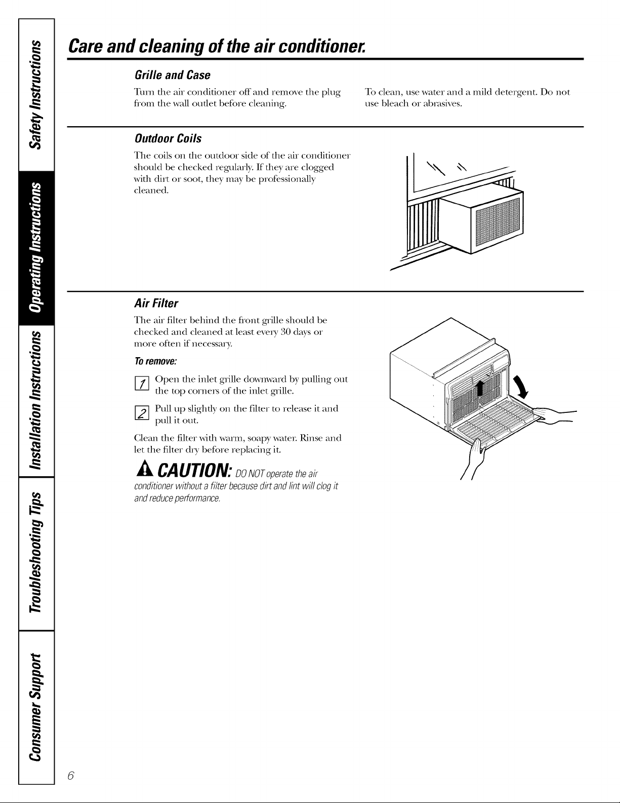
Air Filter
The air filter behind the flont gMlle should be
checked and cleaned at least every 30 days or
more often if necessary:
Toremove:
[_] pen the inlet grille dowmvard by pulling out
the top corne_s of the inlet grille.
[-2-] Pull up slightly on the filter to release it and
pull it out.
Clean file filter Mill warm, soapy wam_. Rinse and
let the filter dry before replacing it.
CAUTION:SONOroperatetheair
conditioner without a filter becausedirt and lint will clog it
andreduceperformance.
6
ilnsta,,at,onnsttuct,onsIAirC°n"it'°nerl
I_ Questions? Call 800.GE.CARES (800.432.2737) or Visit our Website at: ge.com
BEFORE YOU BEGIN
Read these instructions completely
and carefully.
IMPORTANT - Savethese
instructions for local inspector's use.
• IMPORTANT - Observeall
governing codes and ordinances.
• Note to Installer- Be sure to leave these
instructions with the Consumer.
• Note to Consumer- Keep these
instructions for future reference.
• Skill level - Installation of this appliance
requires basic mechanical skills.
• Completion time- Approximately 1 hour
• We recommend that two people install
this product.
• Proper installation is the responsibility
of the installer.
Product failure due to improper installation
is not covered under the Warranty.
You MUST use all supplied parts and use
proper installation procedures as described
in these instructions when installing this
air conditioner.
CAUTION:
Do not, under any circumstances, cut or
remove the third (ground) prong from the
power cord.
Do not change the plug on the power cord
of this air conditioner.
Aluminum house wiring may present special
problemsmconsult a qualified electrician.
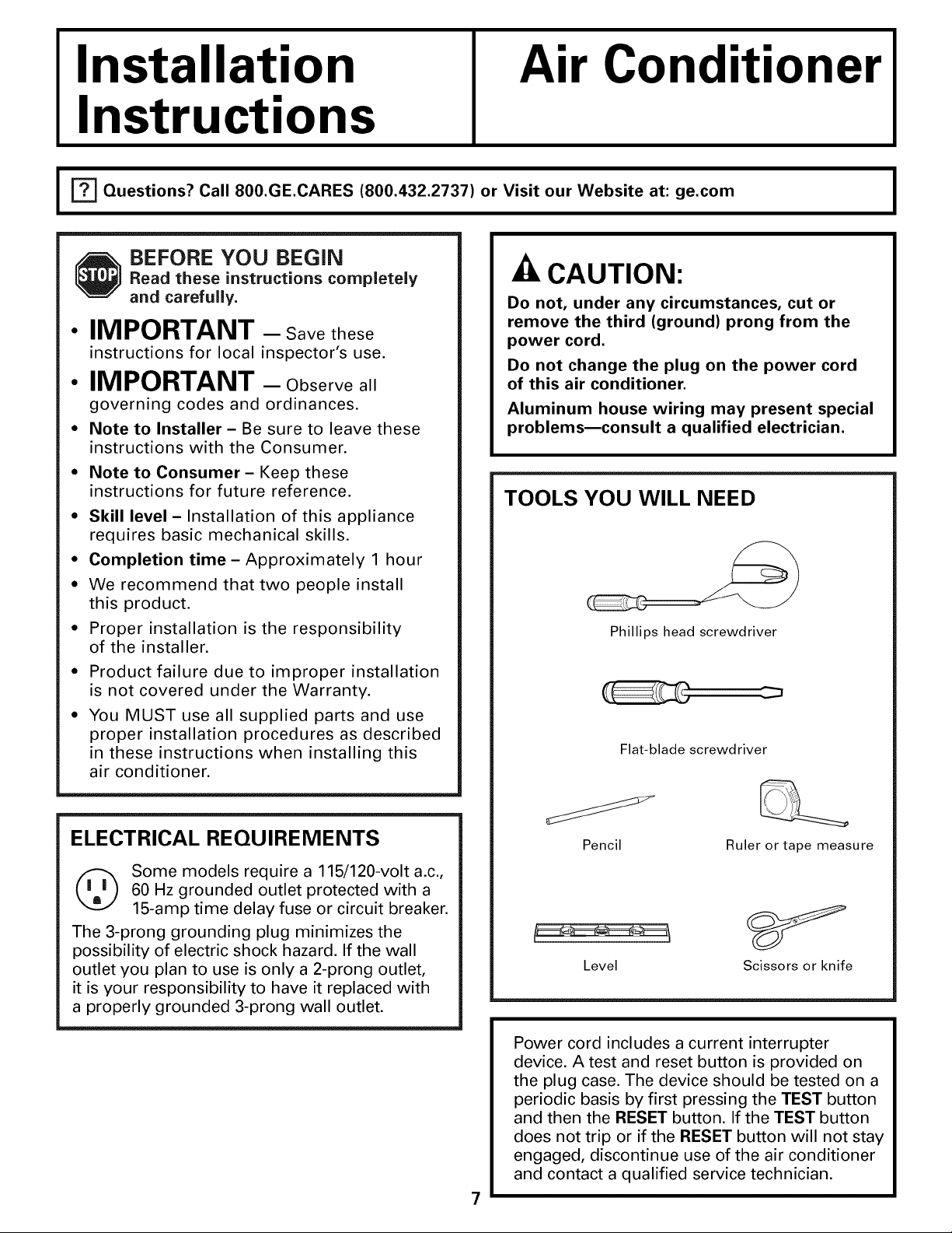
TOOLS YOU WILL NEED
Phillips head screwdriver
Flat-blade screwdriver
I
ELECTRICAL REQUIREMENTS
(_ Some models require a 115/120-volt a.c.,
The 3-prong grounding plug minimizes the
possibility of electric shock hazard. If the wall
outlet you plan to use is only a 2-prong outlet,
it is your responsibility to have it replaced with
a properly grounded 3-prong wall outlet.
60 Hz grounded outlet protected with a
15-amp time delay fuse or circuit breaker.
Pencil Ruler or tape measure
Level Scissors or knife
Power cord includes a current interrupter
device. A test and reset button is provided on
the plug case. The device should be tested on a
periodic basis by first pressing the TEST button
and then the RESET button. If the TEST button
does not trip or if the RESET button will not stay
engaged, discontinue use of the air conditioner
and contact a qualified service technician.
7
Window Installation Instructions
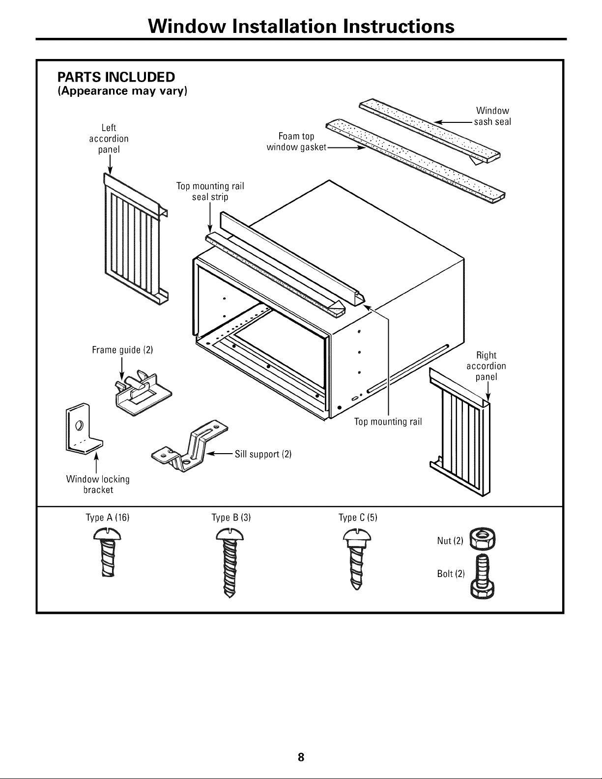
PARTS INCLUDED
(Appearance may vary)
Left
accordion
panel
Topmounting rail
seal strip
Frameguide (2)
_Sill support (2)
Window locking
bracket
TypeA (16) Type B (3) Type C(5)
Right
accordion
)anel
Topmounting rail
Nut (2)
Bolt (2)
8
Window Installation instructions
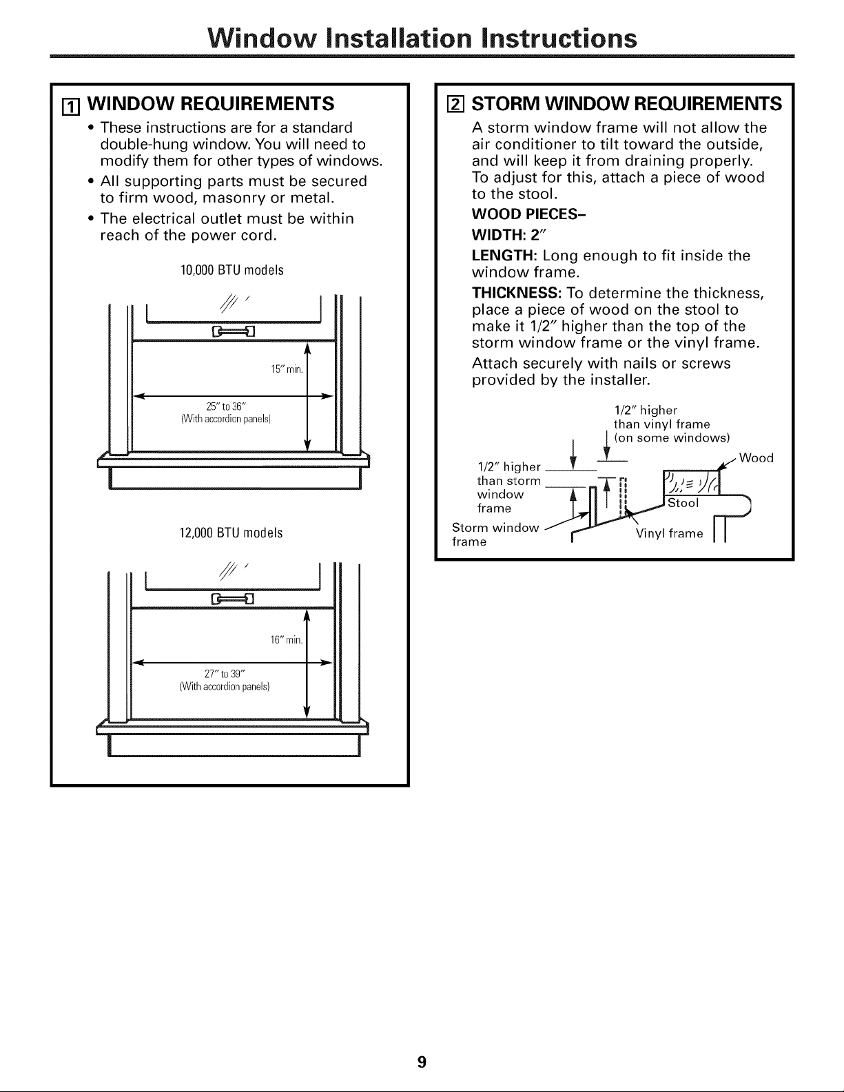
Ill WINDOW REQUIREMENTS
• These instructions are for a standard
double-hung window. You will need to
modify them for other types of windows.
• All supporting parts must be secured
to firm wood, masonry or metal.
• The electrical outlet must be within
reach of the power cord.
10,000BTUmodels
//,
15"min.
25" to36"
(Withaccordionpanels)
12,000BTUmodels
1
[] STORM WINDOW REQUIREMENTS
A storm window frame will not allow the
air conditioner to tilt toward the outside,
and will keep it from draining properly.
To adjust for this, attach a piece of wood
to the stool.
WOOD PIECES-
WIDTH: 2"
LENGTH: Long enough to fit inside the
window frame.
THICKNESS: To determine the thickness,
place a piece of wood on the stool to
make it 1/2" higher than the top of the
storm window frame or the vinyl frame.
Attach securely with nails or screws
provided by the installer.
1/2" higher
than vinyl frame
L (on some windows)
|
w
JL__ / Wood
1/2" higher Z .
than storm T rl YJ, J= _//.I
window -_---rl _1_II
froze
Storm window •
frame J _ _/inyl frame I I
27" to39"
(Withaccordionpanels)
16"min.
9
Window Installation Instructions
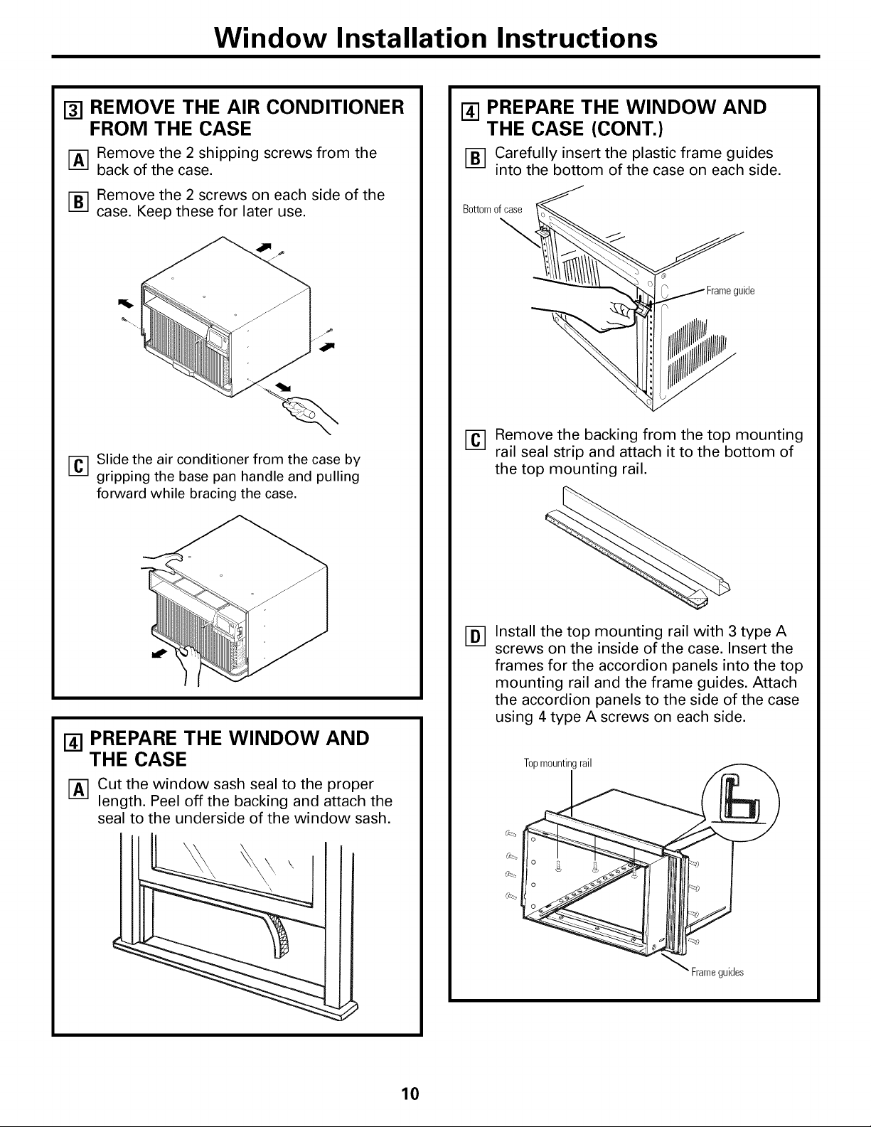
131REMOVE THE AIR CONDITIONER
FROM THE CASE
r-A-] Remove the 2 shipping screws from the
back of the case.
FB1 Remove the 2 screws on each side of the
case. Keep these for later use.
FC-1Slide the air conditioner from the case by
gripping the base pan handle and pulling
forward while bracing the case.
I_1PREPARE THE WINDOW AND
THE CASE (CONT.)
FB1 Carefully insert the plastic frame guides
into the bottom of the case on each side.
Bottomofcase
\
uide
Fc-1 Remove the backing from the top mounting
rail seal strip and attach it to the bottom of
the top mounting rail.
[_] PREPARE THE WINDOW AND
THE CASE
r-A-] Cut the window sash seal to the proper
length. Peel off the backing and attach the
seal to the underside of the window sash.
Install the top mounting rail with 3 type A
®
screws on the inside of the case. Insert the
frames for the accordion panels into the top
mounting rail and the frame guides. Attach
the accordion panels to the side of the case
using 4 type A screws on each side.
Topmountingrail
Frameguides
10
Window Installation Instructions
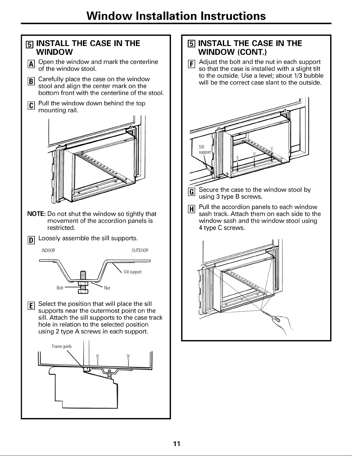
[] INSTALL THE CASE IN THE
WINDOW
[_] Open the window and mark the centerline
of the window stool.
[_] Carefully place the case on the window
stool and align the center mark on the
bottom front with the centerline of the stool.
[] Pull the window down behind the top
mounting rail.
NOTE: Do not shut the window so tightly that
movement of the accordion panels is
restricted.
[] INSTALL THE CASE IN THE
WINDOW (CONT.)
[_] Adjust the bolt and the nut in each support
so that the case is installed with a slight tilt
to the outside. Use a level; about 1/3 bubble
will be the correct case slant to the outside.
i
FG--]Secure the case to the window stool by
using 3 type B screws.
Pull the accordion panels to each window
sash track. Attach them on each side to the
window sash and the window stool using
4 type C screws.
[_] Loosely assemble the sill supports.
INDOOR OUTDOOR
Sillsupport
Select the position that will place the sill
supports near the outermost point on the
sill. Attach the sill supports to the case track
hole in relation to the selected position
using 2 type A screws in each support.
Frameguide
11
 Loading...